KR101772083B1 - Apparatus for controlling compressor and refrigerator having the same - Google Patents
Apparatus for controlling compressor and refrigerator having the sameDownload PDFInfo
- Publication number
- KR101772083B1 KR101772083B1KR1020120009087AKR20120009087AKR101772083B1KR 101772083 B1KR101772083 B1KR 101772083B1KR 1020120009087 AKR1020120009087 AKR 1020120009087AKR 20120009087 AKR20120009087 AKR 20120009087AKR 101772083 B1KR101772083 B1KR 101772083B1
- Authority
- KR
- South Korea
- Prior art keywords
- compressors
- compressor
- switching elements
- inverter
- driving signals
- Prior art date
- Legal status (The legal status is an assumption and is not a legal conclusion. Google has not performed a legal analysis and makes no representation as to the accuracy of the status listed.)
- Active
Links
Images


Classifications
- F—MECHANICAL ENGINEERING; LIGHTING; HEATING; WEAPONS; BLASTING
- F04—POSITIVE - DISPLACEMENT MACHINES FOR LIQUIDS; PUMPS FOR LIQUIDS OR ELASTIC FLUIDS
- F04B—POSITIVE-DISPLACEMENT MACHINES FOR LIQUIDS; PUMPS
- F04B35/00—Piston pumps specially adapted for elastic fluids and characterised by the driving means to their working members, or by combination with, or adaptation to, specific driving engines or motors, not otherwise provided for
- F04B35/04—Piston pumps specially adapted for elastic fluids and characterised by the driving means to their working members, or by combination with, or adaptation to, specific driving engines or motors, not otherwise provided for the means being electric
- F—MECHANICAL ENGINEERING; LIGHTING; HEATING; WEAPONS; BLASTING
- F04—POSITIVE - DISPLACEMENT MACHINES FOR LIQUIDS; PUMPS FOR LIQUIDS OR ELASTIC FLUIDS
- F04B—POSITIVE-DISPLACEMENT MACHINES FOR LIQUIDS; PUMPS
- F04B49/00—Control, e.g. of pump delivery, or pump pressure of, or safety measures for, machines, pumps, or pumping installations, not otherwise provided for, or of interest apart from, groups F04B1/00 - F04B47/00
- F04B49/007—Installations or systems with two or more pumps or pump cylinders, wherein the flow-path through the stages can be changed, e.g. from series to parallel
- F—MECHANICAL ENGINEERING; LIGHTING; HEATING; WEAPONS; BLASTING
- F04—POSITIVE - DISPLACEMENT MACHINES FOR LIQUIDS; PUMPS FOR LIQUIDS OR ELASTIC FLUIDS
- F04B—POSITIVE-DISPLACEMENT MACHINES FOR LIQUIDS; PUMPS
- F04B35/00—Piston pumps specially adapted for elastic fluids and characterised by the driving means to their working members, or by combination with, or adaptation to, specific driving engines or motors, not otherwise provided for
- F04B35/04—Piston pumps specially adapted for elastic fluids and characterised by the driving means to their working members, or by combination with, or adaptation to, specific driving engines or motors, not otherwise provided for the means being electric
- F04B35/045—Piston pumps specially adapted for elastic fluids and characterised by the driving means to their working members, or by combination with, or adaptation to, specific driving engines or motors, not otherwise provided for the means being electric using solenoids
- F—MECHANICAL ENGINEERING; LIGHTING; HEATING; WEAPONS; BLASTING
- F04—POSITIVE - DISPLACEMENT MACHINES FOR LIQUIDS; PUMPS FOR LIQUIDS OR ELASTIC FLUIDS
- F04B—POSITIVE-DISPLACEMENT MACHINES FOR LIQUIDS; PUMPS
- F04B49/00—Control, e.g. of pump delivery, or pump pressure of, or safety measures for, machines, pumps, or pumping installations, not otherwise provided for, or of interest apart from, groups F04B1/00 - F04B47/00
- F04B49/06—Control using electricity
- F04B49/065—Control using electricity and making use of computers
- F—MECHANICAL ENGINEERING; LIGHTING; HEATING; WEAPONS; BLASTING
- F25—REFRIGERATION OR COOLING; COMBINED HEATING AND REFRIGERATION SYSTEMS; HEAT PUMP SYSTEMS; MANUFACTURE OR STORAGE OF ICE; LIQUEFACTION SOLIDIFICATION OF GASES
- F25B—REFRIGERATION MACHINES, PLANTS OR SYSTEMS; COMBINED HEATING AND REFRIGERATION SYSTEMS; HEAT PUMP SYSTEMS
- F25B1/00—Compression machines, plants or systems with non-reversible cycle
- F25B1/02—Compression machines, plants or systems with non-reversible cycle with compressor of reciprocating-piston type
- F—MECHANICAL ENGINEERING; LIGHTING; HEATING; WEAPONS; BLASTING
- F25—REFRIGERATION OR COOLING; COMBINED HEATING AND REFRIGERATION SYSTEMS; HEAT PUMP SYSTEMS; MANUFACTURE OR STORAGE OF ICE; LIQUEFACTION SOLIDIFICATION OF GASES
- F25B—REFRIGERATION MACHINES, PLANTS OR SYSTEMS; COMBINED HEATING AND REFRIGERATION SYSTEMS; HEAT PUMP SYSTEMS
- F25B31/00—Compressor arrangements
- F25B31/02—Compressor arrangements of motor-compressor units
- F25B31/023—Compressor arrangements of motor-compressor units with compressor of reciprocating-piston type
- F—MECHANICAL ENGINEERING; LIGHTING; HEATING; WEAPONS; BLASTING
- F25—REFRIGERATION OR COOLING; COMBINED HEATING AND REFRIGERATION SYSTEMS; HEAT PUMP SYSTEMS; MANUFACTURE OR STORAGE OF ICE; LIQUEFACTION SOLIDIFICATION OF GASES
- F25B—REFRIGERATION MACHINES, PLANTS OR SYSTEMS; COMBINED HEATING AND REFRIGERATION SYSTEMS; HEAT PUMP SYSTEMS
- F25B41/00—Fluid-circulation arrangements
- F25B41/30—Expansion means; Dispositions thereof
- F25B41/385—Dispositions with two or more expansion means arranged in parallel on a refrigerant line leading to the same evaporator
- F—MECHANICAL ENGINEERING; LIGHTING; HEATING; WEAPONS; BLASTING
- F25—REFRIGERATION OR COOLING; COMBINED HEATING AND REFRIGERATION SYSTEMS; HEAT PUMP SYSTEMS; MANUFACTURE OR STORAGE OF ICE; LIQUEFACTION SOLIDIFICATION OF GASES
- F25B—REFRIGERATION MACHINES, PLANTS OR SYSTEMS; COMBINED HEATING AND REFRIGERATION SYSTEMS; HEAT PUMP SYSTEMS
- F25B49/00—Arrangement or mounting of control or safety devices
- F25B49/02—Arrangement or mounting of control or safety devices for compression type machines, plants or systems
- F25B49/022—Compressor control arrangements
- F—MECHANICAL ENGINEERING; LIGHTING; HEATING; WEAPONS; BLASTING
- F25—REFRIGERATION OR COOLING; COMBINED HEATING AND REFRIGERATION SYSTEMS; HEAT PUMP SYSTEMS; MANUFACTURE OR STORAGE OF ICE; LIQUEFACTION SOLIDIFICATION OF GASES
- F25B—REFRIGERATION MACHINES, PLANTS OR SYSTEMS; COMBINED HEATING AND REFRIGERATION SYSTEMS; HEAT PUMP SYSTEMS
- F25B5/00—Compression machines, plants or systems, with several evaporator circuits, e.g. for varying refrigerating capacity
- F25B5/02—Compression machines, plants or systems, with several evaporator circuits, e.g. for varying refrigerating capacity arranged in parallel
- H—ELECTRICITY
- H02—GENERATION; CONVERSION OR DISTRIBUTION OF ELECTRIC POWER
- H02P—CONTROL OR REGULATION OF ELECTRIC MOTORS, ELECTRIC GENERATORS OR DYNAMO-ELECTRIC CONVERTERS; CONTROLLING TRANSFORMERS, REACTORS OR CHOKE COILS
- H02P25/00—Arrangements or methods for the control of AC motors characterised by the kind of AC motor or by structural details
- H02P25/02—Arrangements or methods for the control of AC motors characterised by the kind of AC motor or by structural details characterised by the kind of motor
- H02P25/06—Linear motors
- F—MECHANICAL ENGINEERING; LIGHTING; HEATING; WEAPONS; BLASTING
- F04—POSITIVE - DISPLACEMENT MACHINES FOR LIQUIDS; PUMPS FOR LIQUIDS OR ELASTIC FLUIDS
- F04B—POSITIVE-DISPLACEMENT MACHINES FOR LIQUIDS; PUMPS
- F04B2203/00—Motor parameters
- F04B2203/04—Motor parameters of linear electric motors
- F04B2203/0401—Current
- F—MECHANICAL ENGINEERING; LIGHTING; HEATING; WEAPONS; BLASTING
- F04—POSITIVE - DISPLACEMENT MACHINES FOR LIQUIDS; PUMPS FOR LIQUIDS OR ELASTIC FLUIDS
- F04B—POSITIVE-DISPLACEMENT MACHINES FOR LIQUIDS; PUMPS
- F04B2203/00—Motor parameters
- F04B2203/04—Motor parameters of linear electric motors
- F04B2203/0402—Voltage
- F—MECHANICAL ENGINEERING; LIGHTING; HEATING; WEAPONS; BLASTING
- F05—INDEXING SCHEMES RELATING TO ENGINES OR PUMPS IN VARIOUS SUBCLASSES OF CLASSES F01-F04
- F05B—INDEXING SCHEME RELATING TO WIND, SPRING, WEIGHT, INERTIA OR LIKE MOTORS, TO MACHINES OR ENGINES FOR LIQUIDS COVERED BY SUBCLASSES F03B, F03D AND F03G
- F05B2210/00—Working fluid
- F05B2210/10—Kind or type
- F05B2210/14—Refrigerants with particular properties, e.g. HFC-134a
- F—MECHANICAL ENGINEERING; LIGHTING; HEATING; WEAPONS; BLASTING
- F05—INDEXING SCHEMES RELATING TO ENGINES OR PUMPS IN VARIOUS SUBCLASSES OF CLASSES F01-F04
- F05B—INDEXING SCHEME RELATING TO WIND, SPRING, WEIGHT, INERTIA OR LIKE MOTORS, TO MACHINES OR ENGINES FOR LIQUIDS COVERED BY SUBCLASSES F03B, F03D AND F03G
- F05B2270/00—Control
- F05B2270/30—Control parameters, e.g. input parameters
- F—MECHANICAL ENGINEERING; LIGHTING; HEATING; WEAPONS; BLASTING
- F25—REFRIGERATION OR COOLING; COMBINED HEATING AND REFRIGERATION SYSTEMS; HEAT PUMP SYSTEMS; MANUFACTURE OR STORAGE OF ICE; LIQUEFACTION SOLIDIFICATION OF GASES
- F25B—REFRIGERATION MACHINES, PLANTS OR SYSTEMS; COMBINED HEATING AND REFRIGERATION SYSTEMS; HEAT PUMP SYSTEMS
- F25B1/00—Compression machines, plants or systems with non-reversible cycle
- F25B1/10—Compression machines, plants or systems with non-reversible cycle with multi-stage compression
- F—MECHANICAL ENGINEERING; LIGHTING; HEATING; WEAPONS; BLASTING
- F25—REFRIGERATION OR COOLING; COMBINED HEATING AND REFRIGERATION SYSTEMS; HEAT PUMP SYSTEMS; MANUFACTURE OR STORAGE OF ICE; LIQUEFACTION SOLIDIFICATION OF GASES
- F25B—REFRIGERATION MACHINES, PLANTS OR SYSTEMS; COMBINED HEATING AND REFRIGERATION SYSTEMS; HEAT PUMP SYSTEMS
- F25B2400/00—General features or devices for refrigeration machines, plants or systems, combined heating and refrigeration systems or heat-pump systems, i.e. not limited to a particular subgroup of F25B
- F25B2400/07—Details of compressors or related parts
- F25B2400/073—Linear compressors
- F—MECHANICAL ENGINEERING; LIGHTING; HEATING; WEAPONS; BLASTING
- F25—REFRIGERATION OR COOLING; COMBINED HEATING AND REFRIGERATION SYSTEMS; HEAT PUMP SYSTEMS; MANUFACTURE OR STORAGE OF ICE; LIQUEFACTION SOLIDIFICATION OF GASES
- F25B—REFRIGERATION MACHINES, PLANTS OR SYSTEMS; COMBINED HEATING AND REFRIGERATION SYSTEMS; HEAT PUMP SYSTEMS
- F25B2500/00—Problems to be solved
- F25B2500/26—Problems to be solved characterised by the startup of the refrigeration cycle
- F—MECHANICAL ENGINEERING; LIGHTING; HEATING; WEAPONS; BLASTING
- F25—REFRIGERATION OR COOLING; COMBINED HEATING AND REFRIGERATION SYSTEMS; HEAT PUMP SYSTEMS; MANUFACTURE OR STORAGE OF ICE; LIQUEFACTION SOLIDIFICATION OF GASES
- F25B—REFRIGERATION MACHINES, PLANTS OR SYSTEMS; COMBINED HEATING AND REFRIGERATION SYSTEMS; HEAT PUMP SYSTEMS
- F25B2600/00—Control issues
- F25B2600/02—Compressor control
- F25B2600/021—Inverters therefor
- F—MECHANICAL ENGINEERING; LIGHTING; HEATING; WEAPONS; BLASTING
- F25—REFRIGERATION OR COOLING; COMBINED HEATING AND REFRIGERATION SYSTEMS; HEAT PUMP SYSTEMS; MANUFACTURE OR STORAGE OF ICE; LIQUEFACTION SOLIDIFICATION OF GASES
- F25B—REFRIGERATION MACHINES, PLANTS OR SYSTEMS; COMBINED HEATING AND REFRIGERATION SYSTEMS; HEAT PUMP SYSTEMS
- F25B2600/00—Control issues
- F25B2600/02—Compressor control
- F25B2600/024—Compressor control by controlling the electric parameters, e.g. current or voltage
- F—MECHANICAL ENGINEERING; LIGHTING; HEATING; WEAPONS; BLASTING
- F25—REFRIGERATION OR COOLING; COMBINED HEATING AND REFRIGERATION SYSTEMS; HEAT PUMP SYSTEMS; MANUFACTURE OR STORAGE OF ICE; LIQUEFACTION SOLIDIFICATION OF GASES
- F25B—REFRIGERATION MACHINES, PLANTS OR SYSTEMS; COMBINED HEATING AND REFRIGERATION SYSTEMS; HEAT PUMP SYSTEMS
- F25B2600/00—Control issues
- F25B2600/23—Time delays
- F—MECHANICAL ENGINEERING; LIGHTING; HEATING; WEAPONS; BLASTING
- F25—REFRIGERATION OR COOLING; COMBINED HEATING AND REFRIGERATION SYSTEMS; HEAT PUMP SYSTEMS; MANUFACTURE OR STORAGE OF ICE; LIQUEFACTION SOLIDIFICATION OF GASES
- F25B—REFRIGERATION MACHINES, PLANTS OR SYSTEMS; COMBINED HEATING AND REFRIGERATION SYSTEMS; HEAT PUMP SYSTEMS
- F25B2700/00—Sensing or detecting of parameters; Sensors therefor
- F25B2700/15—Power, e.g. by voltage or current
- F25B2700/151—Power, e.g. by voltage or current of the compressor motor
- Y—GENERAL TAGGING OF NEW TECHNOLOGICAL DEVELOPMENTS; GENERAL TAGGING OF CROSS-SECTIONAL TECHNOLOGIES SPANNING OVER SEVERAL SECTIONS OF THE IPC; TECHNICAL SUBJECTS COVERED BY FORMER USPC CROSS-REFERENCE ART COLLECTIONS [XRACs] AND DIGESTS
- Y02—TECHNOLOGIES OR APPLICATIONS FOR MITIGATION OR ADAPTATION AGAINST CLIMATE CHANGE
- Y02B—CLIMATE CHANGE MITIGATION TECHNOLOGIES RELATED TO BUILDINGS, e.g. HOUSING, HOUSE APPLIANCES OR RELATED END-USER APPLICATIONS
- Y02B30/00—Energy efficient heating, ventilation or air conditioning [HVAC]
- Y02B30/70—Efficient control or regulation technologies, e.g. for control of refrigerant flow, motor or heating
Landscapes
- Engineering & Computer Science (AREA)
- Mechanical Engineering (AREA)
- General Engineering & Computer Science (AREA)
- Physics & Mathematics (AREA)
- Thermal Sciences (AREA)
- Computer Hardware Design (AREA)
- Power Engineering (AREA)
- Control Of Ac Motors In General (AREA)
- Control Of Positive-Displacement Pumps (AREA)
Abstract
Translated fromKoreanDescription
Translated fromKorean본 발명은 하나의 인버터를 이용하여 두 대의 압축기의 운전을 제어하는 압축기 제어 장치 및 이를 포함한 냉장고에 관한 것이다.BACKGROUND OF THE
일반적으로 압축기는 기계적 에너지를 압축성 유체의 압축에너지로 변환시키는 장치로서 냉동기기, 예를 들어 냉장고나 공기조화기 등,의 일부분으로 사용된다.In general, a compressor is a device for converting mechanical energy into compressive energy of a compressible fluid and is used as a part of a refrigeration apparatus, such as a refrigerator or an air conditioner.
압축기는 크게 왕복동식 압축기(Reciprocating Compressor)와, 회전식 압축기(Rotary Compressor)와, 스크롤식 압축기(Scroll Compressor)로 구분된다. 왕복동식 압축기는, 피스톤(Piston)과 실린더(Cylinder) 사이에 작동가스가 흡입 또는 토출되는 압축공간이 형성되도록 하여 피스톤이 실린더 내부에서 직선 왕복 운동하면서 냉매를 압축시킨다. 회전식 압축기는, 편심 회전되는 롤러(Roller)와 실린더 사이에 작동가스가 흡입 또는 토출되는 압축공간이 형성되도록 하여 롤러가 실린더 내벽을 따라 편심 회전되면서 냉매를 압축시킨다. 스크롤식 압축기는, 선회 스크롤(Orbiting Scroll)과 고정 스크롤(Fixed Scroll) 사이에 작동가스가 흡입 또는 토출되는 압축공간이 형성되도록 하여 신회 스크롤이 고정 스크롤을 따라 회전되면서 냉매를 압축시킨다.Compressors are largely divided into Reciprocating Compressors, Rotary Compressors, and Scroll Compressors. In the reciprocating compressor, a compression space in which an operating gas is sucked or discharged is formed between a piston and a cylinder, so that the piston linearly reciprocates within the cylinder and compresses the refrigerant. The rotary compressor compresses the refrigerant while eccentrically rotating the roller along the inner wall of the cylinder so that a compression space in which the working gas is sucked or discharged is formed between the roller and the cylinder. In the scroll type compressor, a compression space is formed between an orbiting scroll and a fixed scroll to suck or discharge an operating gas, thereby compressing the refrigerant while the newbear scroll is rotated along the fixed scroll.
왕복동식 압축기는 내부 피스톤을 실린더의 내부에서 선형으로 왕복 운동시킴으로써 냉매 가스를 흡입, 압축 및 토출한다. 왕복동식 압축기는 피스톤을 구동하는 방식에 따라 크게 레시프로(Recipro) 방식과 리니어(Linear) 방식으로 구분된다.The reciprocating compressor sucks, compresses, and discharges the refrigerant gas by linearly reciprocating the inner piston inside the cylinder. Reciprocating compressors are largely divided into Recipro type and Linear type depending on the method of driving the pistons.
레시프로 방식이라 함은 회전하는 모터(Motor)에 크랭크샤프트(Crankshaft)를 결합하고, 크랭크샤프트에 피스톤을 결합하여 모터의 회전 운동을 직선 왕복운동으로 변환하는 방식이다. 반면, 리니어 방식이라 함은 직선 운동하는 모터의 가동자에 피스톤을 연결하여 모터의 직선 운동으로 피스톤을 왕복운동시키는 방식이다.In the reco-pro system, a crankshaft is coupled to a rotating motor, and a piston is coupled to a crankshaft to convert a rotational motion of the motor into a linear reciprocating motion. On the other hand, the linear system refers to a system in which a piston is connected to a mover of a motor that linearly moves, and the piston reciprocates by rectilinear motion of the motor.
이러한 왕복동식 압축기는 구동력을 발생하는 전동 유닛과, 전동 유닛으로부터 구동력을 전달받아 유체를 압축하는 압축 유닛으로 구성된다. 전동 유닛으로는 일반적으로 모터(motor)를 많이 사용하며, 상기 리니어 방식의 경우에는 리니어 모터(linear motor)를 이용한다.Such a reciprocating compressor includes an electric unit that generates a driving force and a compression unit that receives a driving force from the electric unit and compresses the fluid. Generally, a motor is used as the electric unit, and a linear motor is used in the case of the linear type.
리니어 모터는 모터 자체가 직선형의 구동력을 직접 발생시키므로 기계적인 변환 장치가 필요하지 않고, 구조가 복잡하지 않다. 또한, 리니어 모터는 에너지 변환으로 인한 손실을 줄일 수 있고, 마찰 및 마모가 발생하는 연결 부위가 없어서 소음을 크게 줄일 수 있는 특징을 가지고 있다. 또한, 리니어 방식의 왕복동식 압축기(이하, 리니어 압축기(Linear Compressor)라 함)를 냉장고나 공기조화기에 이용할 경우에는 리니어 압축기에 인가되는 스트로크 전압을 변경하여 줌에 따라 압축 비(Compression Ratio)를 변경할 수 있어 냉력(Freezing Capacity) 가변 제어에도 사용할 수 있는 장점이 있다.In the linear motor, since the motor itself generates a linear driving force, a mechanical conversion device is not necessary, and the structure is not complicated. In addition, the linear motor can reduce losses due to energy conversion, and has no connecting parts where friction and abrasion occur, thus greatly reducing noise. When a reciprocating compressor of a linear type (hereinafter referred to as a linear compressor) is used for a refrigerator or an air conditioner, the compression ratio is changed according to the change of the stroke voltage applied to the linear compressor. And can be used for variable control of freezing capacity.
한편, 왕복동식 압축기, 특히 리니어 압축기는 피스톤이 실린더 안에서 기구적으로 구속되어 있지 않은 상태에서 왕복 운동을 하게 되기 때문에 갑자기 전압이 과도하게 걸리는 경우에 피스톤이 실린더 벽에 부딪히거나, 부하가 커서 피스톤이 전진하지 못하여 압축이 제대로 이루어지지 않을 수 있다. 따라서, 부하의 변동이나 전압의 변동에 대하여 피스톤의 운동을 제어하기 위한 제어 장치가 필수적이다.On the other hand, since the reciprocating compressor, particularly the linear compressor, reciprocates in a state in which the piston is not mechanically restrained in the cylinder, when the voltage suddenly becomes excessive, the piston hits against the cylinder wall, Can not go forward and compression can not be done properly. Therefore, a control device for controlling the motion of the piston with respect to the load variation or the voltage variation is essential.
일반적으로 압축기 제어 장치는 압축기 모터에 인가되는 전압과 전류를 검출하여 센서리스 방법으로 스트로크를 추정하여 피드백 제어를 수행한다. 이때, 압축기 제어 장치는 압축기를 제어하기 위한 수단으로 트라이악(Triac)이나 인버터(inverter)를 구비한다.Generally, a compressor control device detects a voltage and a current applied to a compressor motor and performs a feedback control by estimating a stroke by a sensorless method. At this time, the compressor control device includes a triac or an inverter as means for controlling the compressor.
인버터를 적용한 압축기 제어 장치는 일반적으로 하나의 인버터를 이용하여 하나의 압축기만을 제어하였다. 예를 들어, 냉동실과 냉장실을 구비한 냉장고의 경우에, 인버터를 2개 사용하여 독립 제어를 수행함으로써 각 실에 대해 냉매 사이클을 구현하였다.In general, only one compressor is used to control a single compressor. For example, in the case of a refrigerator having a freezer compartment and a refrigerating compartment, a refrigerant cycle is implemented for each compartment by performing independent control using two inverters.
본 발명의 실시 예들은 하나의 인버터를 이용하여 두 대의 압축기를 개별 운전하거나 동시 운전할 수 있는 압축기 제어 장치 및 이를 포함한 냉장고를 제공하는 데에 일 목적이 있다.Embodiments of the present invention are directed to a compressor control apparatus and a refrigerator including the same, which can operate or simultaneously operate two compressors by using one inverter.
본 발명의 실시 예들은 하나의 인버터를 이용하여 두 대의 압축기를 운전함에 있어서 인버터를 구성하는 스위칭 소자들의 주파수를 달리함으로써 동시 운전이 가능하도록 한 압축기 제어 장치 및 이를 포함한 냉장고를 제공하는 데에 다른 목적이 있다.Embodiments of the present invention provide a compressor control apparatus and a refrigerator including the same that enable simultaneous operation by changing the frequency of switching elements constituting an inverter when two compressors are operated by using one inverter, .
일 실시 예에 따른 압축기 제어 장치는, 세 쌍의 스위칭 소자들을 구비하고, 상기 세 쌍의 스위칭 소자들 중 한 쌍의 스위칭 소자는 제1 및 제2 압축기에 공통으로 연결되며, 각 쌍의 스위칭 소자들에 대한 구동 신호들에 따라 스위칭하는 하나의 인버터와, 상기 제1 및 제2 압축기의 부하 상태에 따라 상기 구동 신호들로 구성된 인버터 제어 신호를 생성하여 상기 하나의 인버터에 출력하는 제어 유닛을 포함하고, 상기 공통으로 연결되는 한 쌍의 스위칭 소자에 대한 구동 신호는, 다른 쌍의 스위칭 소자들에 대한 구동 신호들보다 느린 주파수를 가진다.The compressor control apparatus according to an embodiment includes three pairs of switching elements, a pair of switching elements of the three pairs of switching elements are commonly connected to the first and second compressors, And a control unit for generating an inverter control signal composed of the driving signals according to a load state of the first and second compressors and outputting the generated inverter control signals to the one inverter And the driving signals for the pair of switching elements connected in common have a frequency that is slower than the driving signals for the other pair of switching elements.
상기 압축기 제어 장치에 있어서, 상기 제어 유닛은, 상기 공통으로 연결되는 한 쌍의 스위칭 소자에 대한 구동 신호는 운전 주파수를 갖도록 한다.In the compressor control apparatus, the control unit causes the driving signals for the pair of switching elements connected in common to have an operating frequency.
또, 일 실시 예에 따른 압축기 제어 장치는, 상용 교류 전원을 직류 전원으로 정류하는 컨버터와, 상기 정류된 직류 전원을 평활화하고 저장하는 평활 유닛과, 상기 인버터 제어 신호를 입력받아 상기 구동 신호들을 상기 하나의 인버터에 출력하는 구동 유닛을 더 포함하여 구성된다.According to another aspect of the present invention, there is provided a compressor control apparatus including: a converter for rectifying a commercial AC power source to a DC power source; a smoothing unit for smoothing and storing the rectified DC power source; And a drive unit for outputting the drive signal to one inverter.
일 실시 예에 따른 냉장고는, 냉장고 본체와, 상기 냉장고 본체에 구비되고 냉매를 각각 압축하는 제1 및 제2 압축기와, 세 쌍의 스위칭 소자들을 구비하고, 각 쌍의 스위칭 소자들에 대한 구동 신호들에 따라 스위칭하는 하나의 인버터와, 상기 제1 및 제2 압축기의 부하를 검출하는 제1 및 제2 부하 검출 유닛과, 상기 제1 및 제2 압축기의 부하 상태에 따라 상기 구동 신호들로 구성된 인버터 제어 신호를 생성하여 상기 하나의 인버터에 출력하는 제어 유닛을 포함하여 구성된다. 여기서, 상기 하나의 인버터 내에 구비된 상기 세 쌍의 스위칭 소자들 중 한 쌍의 스위칭 소자는, 상기 제1 및 제2 압축기에 공통으로 연결되고 운전 주파수로 스위칭한다.According to an embodiment of the present invention, there is provided a refrigerator comprising: a refrigerator body; first and second compressors provided in the refrigerator body to compress refrigerant, respectively; and three pairs of switching elements, A second load detection unit for detecting a load of the first and second compressors, and a second load detection unit for detecting a load of the first and second compressors, And a control unit for generating and outputting an inverter control signal to the one inverter. Here, a pair of switching elements among the three pairs of switching elements provided in the one inverter is commonly connected to the first and second compressors and switches at an operating frequency.
본 발명의 실시 예들은 하나의 인버터를 이용하여 두 대의 압축기의 운전을 제어함으로써 소자의 사용을 최소화하면서 압축기 용량을 확대하고 시스템의 운전 효율을 증대한다.Embodiments of the present invention increase the compressor capacity and increase the operating efficiency of the system while minimizing the use of elements by controlling the operation of two compressors using one inverter.
본 발명의 실시 예들은 두 대의 압축기를 이용하여 부하나 냉력에 대응하여 복수의 운전 모드를 사용할 수 있다. 또, 본 발명은 하나의 인버터를 이용하여 두 대의 압축기를 개별 또는 동시 운전함으로써 시스템의 구성을 간소화하여 비용을 줄일 수 있다.Embodiments of the present invention can use a plurality of operation modes in response to cooling or cooling by using two compressors. Further, the present invention simplifies the structure of the system by reducing the cost by operating two compressors individually or simultaneously using one inverter.
본 발명의 실시 예들은 하나의 인버터를 이용하여 두 대의 압축기를 운전함에 있어서 공통으로 사용되는 스위칭 소자들을 다른 스위칭 소자들과 달리 운전 주파수로 스위칭함으로써 두 대의 압축기의 동시 운전을 가능하게 하고, 스위칭 손실을 저감하며, 시스템의 효율 및 안정성을 제고한다.Embodiments of the present invention enable simultaneous operation of two compressors by switching switching elements commonly used in operation of two compressors by using one inverter at an operation frequency different from other switching elements, , Thereby improving the efficiency and stability of the system.
도 1 및 도 2는 본 발명의 실시 예들에 따른 압축기 제어 장치의 구성을 개략적으로 보인 도;
도 3은 도 1 또는 도 2에서의 압축기 제어 장치를 개략적으로 보인 회로도;
도 4a 및 도 4b는 본 발명의 실시 예들에 따라 두 대의 압축기 중 제1 압축기의 운전을 제어하는 동작을 설명하기 위한 도;
도 5는 두 대의 압축기 중 제1 압축기에 연결된 스위칭 소자들의 스위칭 주파수를 보인 도;
도 6a 및 도 6b은 본 발명의 실시 예들에 따라 두 대의 압축기 중 제2 압축기의 운전을 제어하는 동작을 설명하기 위한 도;
도 7은 두 대의 압축기 중 제2 압축기에 연결된 스위칭 소자들의 스위칭 주파수를 보인 도;
도 8a 내지 도 9b는 본 발명의 실시 예들에 따라 두 대의 압축기를 동시 운전하는 동작을 설명하기 위한 도;
도 10은 두 대의 압축기를 동시 운전할 때의 스위칭 소자들의 스위칭 주파수를 보인 도;
도 11은 일 실시 예에 따른 압축기 제어 방법을 개략적으로 도시한 흐름도;
도 12는 본 발명의 실시 예들에 따른 압축기 제어 장치를 구비한 리니어 압축기를 보인 단면도; 및
도 13은 도 12의 리니어 압축기를 적용한 냉장고를 보인 사시도이다.FIG. 1 and FIG. 2 are views schematically showing a configuration of a compressor control apparatus according to embodiments of the present invention;
Fig. 3 is a circuit diagram schematically showing the compressor control apparatus in Fig. 1 or Fig. 2; Fig.
4A and 4B are views for explaining an operation of controlling the operation of the first compressor among the two compressors according to the embodiments of the present invention;
Figure 5 shows the switching frequency of the switching elements of the two compressors connected to the first compressor;
6A and 6B are diagrams for explaining an operation of controlling the operation of the second compressor among the two compressors according to the embodiments of the present invention;
Figure 7 shows the switching frequency of the switching elements connected to the second compressor of the two compressors;
8A to 9B are views for explaining the operation of simultaneously operating two compressors according to the embodiments of the present invention;
10 is a view showing switching frequencies of switching elements when two compressors are operated simultaneously;
11 is a flow diagram schematically illustrating a method of controlling a compressor according to an embodiment;
12 is a sectional view of a linear compressor having a compressor control apparatus according to embodiments of the present invention; And
FIG. 13 is a perspective view showing a refrigerator to which the linear compressor of FIG. 12 is applied.
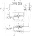
도 1 내지 도 3을 참조하면, 일 실시 예에 따른 압축기 제어 장치는, 세 쌍의 스위칭 소자들을 구비하고, 상기 세 쌍의 스위칭 소자들 중 한 쌍의 스위칭 소자는 제1 및 제2 압축기(C1, C2)에 공통으로 연결되며, 각 쌍의 스위칭 소자들에 대한 구동 신호들에 따라 스위칭하는 하나의 인버터(40)와, 상기 제1 및 제2 압축기(C1, C2)의 부하 상태에 따라 상기 구동 신호들로 구성된 인버터 제어 신호를 생성하여 상기 하나의 인버터(40)에 출력하는 제어 유닛(50)을 포함하여 구성된다. 인버터(40)는 세 쌍의 스위칭 소자들(S1 내지 S6)에 각각 병렬 접속되는 프리휠링 다이오드들(Freewheeling Diode)을 더 포함할 수 있다.1 to 3, a compressor control apparatus according to an embodiment includes three pairs of switching elements, and one pair of switching elements of the three pairs of switching elements is connected to the first and second compressors C1 (C2), and switching according to the driving signals for the respective pairs of switching elements; and a second inverter (40) connected in common to the first and second compressors And a control unit (50) for generating and outputting an inverter control signal composed of driving signals to the one inverter (40). The
여기서, 도 3을 참조하면, 상기 공통으로 연결되는 한 쌍의 스위칭 소자(S3, S4)에 대한 구동 신호는, 다른 쌍의 스위칭 소자들(S1, S2, S5, S6)에 대한 구동 신호들보다 느린 주파수를 가진다. 특히, 상기 제어 유닛(50)은, 상기 공통으로 연결되는 한 쌍의 스위칭 소자(S3, S4)에 대한 구동 신호는 운전 주파수를 갖도록 한다. 각 구동 신호로는 일반적으로 SVPWM(Space Vector Pulse Width Modulation) 등을 PWM 신호를 사용한다. 즉, 공통으로 연결되는 한 쌍의 스위칭 소자(S3, S4)는 운전 주파수로 스위칭하고, 다른 스위칭 소자들(S1, S2, S5, S6)에 대한 구동 신호는 각 압축기를 운전하기 위한 PWM 반송파 주파수를 가진다.3, the driving signals for the pair of switching elements S3 and S4 connected in common are different from the driving signals for the other pair of switching elements S1, S2, S5 and S6 It has a slow frequency. In particular, the
여기서, 제1 및 제2 압축기(C1, C2) 중 적어도 하나는 왕복동식 압축기, 특히 리니어 압축기일 수 있다. 또, 두 대의 압축기는 서로 용량이 다르게 구성될 수 있다. 제1 및 제2 압축기는 하나의 인버터를 이용한 압축기 제어 장치에 의해 동시에 운전될 수도 있고, 각각 개별 운전될 수 있다. 이를 간단히 압축기 운전 모드로 정의할 수 있다. 압축기 운전 모드는, 제1 및 제2 압축기의 부하 또는 필요한 냉력 등에 의해 결정되는 운전 모드이다. 압축기 운전 모드는, 각 압축기의 스트로크, 주파수 등을 일정 값으로 구분하여 제어하는 운전 모드일 수 있다. 여기서, 상기 압축기 운전 모드는, 간단히 제1 압축기의 개별 운전 모드, 제2 압축기의 개별 운전 모드, 제1 및 제2 압축기의 동시 운전 모드로 구분할 수 있다.Here, at least one of the first and second compressors (C1, C2) may be a reciprocating compressor, particularly a linear compressor. Further, the two compressors may be configured to have different capacities from each other. The first and second compressors may be operated simultaneously by the compressor control device using one inverter, or may be operated individually. This can be simply defined as the compressor operating mode. The compressor operating mode is an operating mode determined by the loads of the first and second compressors, the required cooling power, and the like. The compressor operation mode may be an operation mode in which the stroke, frequency, etc. of each compressor are classified and controlled. Here, the compressor operation mode can be divided into an individual operation mode of the first compressor, an individual operation mode of the second compressor, and a simultaneous operation mode of the first and second compressors.
도 12를 참조하면, 상기 제1 압축기 또는 제2 압축기는, 가스흡입관(SP)과 가스토출관(DP)이 연통되는 케이싱(100)과, 상기 케이싱(100)의 내부에 탄력 지지되는 프레임유닛(200)과, 상기 프레임유닛(200)에 지지되어 가동자(330)가 직선으로 왕복운동을 하는 모터(300)와, 상기 모터(300)의 가동자(330)에 피스톤(420)이 결합되어 상기 프레임유닛(200)으로 지지되는 압축유닛(400)과, 상기 모터(300)의 가동자(330)와 상기 압축유닛(400)의 피스톤(420)을 운동방향으로 탄력 지지하여 공진운동을 유도하는 복수 개의 공진유닛(500)을 포함한다.12, the first compressor or the second compressor includes a
상기 프레임유닛(200)은 상기 압축유닛(400)이 지지되고 상기 모터(300)의 전방측을 지지하는 제1 프레임(210)과, 상기 제1 프레임(210)에 결합되어 상기 모터(300)의 후방측을 지지하는 제2 프레임(220)과, 상기 제2 프레임(220)에 결합되어 복수 개의 제2 공진스프링들(530)을 지지하는 제3 프레임(230)으로 이루어진다. 상기 제1 프레임(210)과 제2 프레임(220) 그리고 제3 프레임(230)은 모두 철손을 줄일 수 있도록 알루미늄과 같은 비자성체로 형성될 수 있다.The
그리고 상기 제1 프레임(210)은 환형 판체 모양으로 프레임부(211)가 형성되고, 상기 프레임부(211)의 중앙에는 실린더(410)가 삽입되도록 원통모양의 실린더부(212)가 후방면, 즉 모터 방향으로 길게 일체로 형성된다. 상기 프레임부(211)는 모터(300)의 외측고정자(310)와 내측고정자(320)를 모두 지지할 수 있도록 상기 프레임부(211)의 외경이 상기 모터(300)의 외측고정자(310)의 내경 보다는 적어도 작지 않게 형성되는 것이 바람직하다.The first frame 210 is formed with a
그리고 상기 제1 프레임(210)은 상기 실린더부(212)의 외주면에 상기 내측고정자(320)가 삽입되어 고정된다. 이 경우, 자력손실을 방지할 수 있도록 상기 제1 프레임(210)은 알루미늄과 같은 비자성체로 형성되는 것이 바람직하다. 그리고 상기 실린더부(212)는 실린더(410)에 인서트 다이캐스팅 공법을 이용하여 일체로 형성될 수 있다. 하지만, 상기 실린더부(212)는 그 내주면에 상기 실린더(410)를 압입하거나 또는 나사산을 형성하여 나사 조립할 수도 있다. 그리고 상기 실린더부(212)는 그 전방측 내주면과 후방측 내주면 사이에 단차면 또는 경사면이 형성되어 상기 실린더부(212)의 내주면에 결합되는 상기 실린더(410)가 피스톤 방향으로 지지될 수 있도록 하는 것이 상기 실린더(410)의 안정성 측면에서 바람직할 수 있다.The first frame 210 has the
상기 모터(300)는 상기 제1 프레임(210)과 제2 프레임(220) 사이에 지지되고 코일(311)이 권선되는 외측고정자(310)와, 상기 외측고정자(310)의 안쪽에 일정 간격을 두고 결합되어 상기 실린더부(212)에 삽입되는 내측고정자(320)와, 상기 외측고정자(310)의 코일(311)에 대응되도록 자석(331)이 구비되어 상기 외측고정자(310)와 내측고정자(320) 사이에서 자속 방향을 따라 직선으로 왕복운동을 하는 가동자(330)로 이루어진다. 상기 외측고정자(310)와 내측고정자(320)는 다수 장의 얇은 스테이터코어를 낱장씩 원통형으로 적층하거나 또는 다수 장의 얇은 스테이터코어를 블록모양으로 적층하여 그 스테이터블록을 방사상으로 적층하여 이루어진다.The
상기 압축유닛(400)은 상기 제1 프레임(210)에 일체로 형성되는 실린더(410)와, 상기 모터(300)의 가동자(330)에 결합되어 상기 실린더(410)의 압축공간(P)에서 왕복운동을 하는 피스톤(420)과, 상기 피스톤(420)의 선단에 장착되어 그 피스톤(420)의 흡입유로(421)를 개폐하면서 냉매가스의 흡입을 조절하는 흡입밸브(430)와, 상기 실린더(410)의 토출측에 장착되어 상기 실린더(410)의 압축공간(P)을 개폐하면서 압축가스의 토출을 조절하는 토출밸브(440)와, 상기 토출밸브(440)를 탄력적으로 지지하는 밸브스프링(450)과, 상기 토출밸브(440)와 밸브스프링(450)을 수용하도록 상기 실린더(410)의 토출측에서 상기 제1 프레임(210)에 고정되는 토출커버(460)로 이루어진다.The
상기 실린더(410)는 원통모양으로 형성되어 상기 제1 프레임(210)의 실린더부(212)에 삽입 결합된다.The
상기 실린더(410)는 그 내주면이 주철로 된 피스톤(420)과 베어링면을 형성함에 따라 상기 피스톤(420)에 의한 마모를 고려하여 주철이나 적어도 제1 프레임(210), 보다 정확하게는 실린더부(212)의 경도보다 높은 재질로 형성될 수 있다.As the inner circumferential surface of the
상기 피스톤(420)은 상기 실린더(410)의 재질과 동일한 재질로 형성되거나 적어도 경도가 비슷한 재질로 형성되는 것이 상기 실린더(410)와의 마모를 줄일 수 있어 바람직하다. 그리고 상기 피스톤(420)의 내부에는 냉매가 상기 실린더(410)의 압축실(P)로 흡입되도록 흡입유로(421)가 관통 형성된다.The
상기 공진유닛(500)은 상기 가동자(330)와 피스톤(420)의 연결부에 결합되는 스프링서포터(510)와, 상기 스프링서포터(510)의 전방측에 지지되는 제1 공진스프링들(520)과, 상기 스프링서포터(510)의 후방측에 지지되는 제2 공진스프링들(530)로 이루어진다.The
도면 중 미설명 부호인 422는 피스톤 연결부, 600은 오일피더이다.In the drawing,
모터(300)에 전원이 인가되어 상기 외측고정자(310)와 내측고정자(320)의 사이에 자속이 형성되면, 상기 외측고정자(310)와 내측고정자(320) 사이의 공극에 놓인 상기 가동자(330)가 자속의 방향을 따라 움직이면서 상기 공진유닛(500)에 의해 지속적으로 왕복운동을 하게 된다. 그리고 상기 피스톤(420)이 상기 실린더(410)의 내부에서 후진운동을 할 때 상기 케이싱(100)의 내부공간에 채워져 있던 냉매가 상기 피스톤(420)의 흡입유로(421)와 상기 흡입밸브(430)를 통과하여 상기 실린더(410)의 압축공간(P)으로 흡입된다. 그리고 상기 피스톤(420)이 실린더(410)의 내부에서 전진운동을 할 때 상기 압축공간(P)으로 흡입된 냉매가스가 압축되어 상기 토출밸브(440)를 열면서 토출하는 일련의 과정을 반복하게 된다.When power is applied to the
본 발명의 실시 예들에 따른 리니어 압축기는 하기와 같은 압축기 제어 장치를 구비한다. 또, 상기 리니어 압축기는 냉장고 또는 공기 조화기와 같은 냉동기기에 폭넓게 사용될 수 있다. 제1 및 제2 압축기를 도 13에 도시한 바와 같이 냉장고에 적용할 경우, 각 압축기가 냉장실 및 냉동실을 담당하도록 설계될 수 있다.The linear compressor according to the embodiments of the present invention includes a compressor control device as described below. In addition, the linear compressor can be widely used in refrigeration equipment such as a refrigerator or an air conditioner. When the first and second compressors are applied to a refrigerator as shown in FIG. 13, each compressor can be designed to take charge of the refrigerator and the freezer.
도 1 내지 도 3과 함께 도 13을 참조하면, 일 실시 예에 따른 냉장고(700)는, 냉장고 본체와, 상기 냉장고 본체에 구비되고 냉매를 각각 압축하는 제1 및 제2 압축기와, 세 쌍의 스위칭 소자들을 구비하고, 각 쌍의 스위칭 소자들에 대한 구동 신호들에 따라 스위칭하는 하나의 인버터와, 상기 제1 및 제2 압축기의 부하를 검출하는 제1 및 제2 부하 검출 유닛과, 상기 제1 및 제2 압축기의 부하 상태에 따라 상기 구동 신호들로 구성된 인버터 제어 신호를 생성하여 상기 하나의 인버터에 출력하는 제어 유닛을 포함하여 구성된다. 여기서, 상기 하나의 인버터 내에 구비된 상기 세 쌍의 스위칭 소자들 중 한 쌍의 스위칭 소자는, 상기 제1 및 제2 압축기에 공통으로 연결되고 운전 주파수로 스위칭한다.Referring to FIG. 13 together with FIGS. 1 to 3, a
도 13을 참조하면, 상기 냉장고(700)는 그 내부에 냉장고의 운전 전반을 제어하는 메인기판(710)이 구비되고, 제1 및 제2 압축기(C1, C2)가 연결된다. 상기 압축기 제어 장치는 메인기판(710)에 구비될 수 있다. 냉장고(700)는 제1 및 제2 압축기의 구동에 의해 동작한다. 냉장고의 내부에 공급되는 냉기는 냉매의 열교환 작용에 의해서 생성되고, 압축-응축-팽창-증발의 사이클(Cycle)을 반복적으로 수행하면서 지속적으로 냉장고의 내부로 공급된다. 공급된 냉매는 대류에 의해서 냉장고 내부에 고르게 전달되어 냉장고 내부의 음식물을 원하는 온도로 저장할 수 있게 된다.Referring to FIG. 13, the
일 실시 예에 따른 압축기 제어 장치는, 상용 교류 전원(10)을 직류 전원으로 정류하는 컨버터(20)와, 상기 정류된 직류 전원을 평활화하고 저장하는 평활 유닛(30)과, 상기 인버터 제어 신호를 입력받아 상기 구동 신호들을 상기 하나의 인버터에 출력하는 구동 유닛(70)을 더 포함하여 구성된다. 예를 들어, 구동 유닛(70)은 인버터 제어 신호에 따라 인버터의 스위칭 소자들이 IGBT 등일 때, 스위칭 소자들에 대한 입력 전압, 즉 게이트 전압을 출력한다. 도 3을 참조하면, 컨버터(20)는, 두 쌍의 다이오드들(D1, D2, D3, D4)로 구성된 풀 브리지 컨버터일 수 있다.The compressor control apparatus according to an embodiment includes a
도 1을 참조하면, 상기 압축기 제어 장치는, 상기 압축기의 부하를 검출하는 제1 및 제2 부하 검출 유닛(61, 62)을 더 포함할 수 있다. 이때, 상기 제어 유닛(50)은, 상기 부하에 따라 인버터(40)를 제어하는 인버터 제어 신호를 생성한다. 즉, 제어 유닛(50)은 제1 및 제2 압축기(C1, C2)의 부하를 근거로 상기 인버터 제어 신호를 생성하여 상기 제1 및 제2 압축기를 개별 운전하거나, 동시 운전한다. 제어 유닛(50)은, 상기 제1 및 제2 압축기(C1, C2)의 제1 및 제2 스트로크와, 상기 제1 및 제2 압축기에 대한 스트로크 지령치를 이용하여 상기 인버터 제어 신호를 생성한다. 여기서, 압축기의 부하는 모터 전류, 모터 전압, 스트로크, 이들의 위상차, 주파수 등이다. 예를 들어, 냉장고에 압축기가 구비된 경우에는, 냉장고의 부하를 이용하여 압축기의 부하를 검출할 수 있다.Referring to FIG. 1, the compressor control apparatus may further include first and second load detection units (61, 62) for detecting a load of the compressor. At this time, the
도 2를 참조하면, 상기 압축기 제어 장치는, 상기 제1 압축기(C1) 내에 구비된 제1 모터에 인가되는 제1 모터 구동 전류를 검출하는 제1 전류 검출 유닛(611)과, 제1 모터에 인가되는 제1 모터 구동 전압을 검출하는 제1 전압 검출 유닛(612)을 더 포함하여 구성된다. 또, 상기 압축기 제어 장치는, 제2 압축기(C2) 내에 구비된 제2 모터에 인가되는 제2 모터 구동 전류를 검출하는 제2 전류 검출 유닛(621)과, 제2 모터에 인가되는 제2 모터 구동 전압을 검출하는 제2 전압 검출 유닛(622)을 더 포함하여 구성된다.2, the compressor control apparatus includes a first current detecting
제1 및 제2 전류 검출 유닛(611, 621)은 압축기의 부하, 또는 냉동기기의 부하,에 따라 압축기에 인가되는 구동 전류를 검출한다. 상기 전류 검출 유닛들은 압축기 모터에 인가되는 모터 전류를 검출한다. 제1 및 제2 전압 검출 유닛(612, 622)은 압축기에 인가되는 구동 전압을 검출한다. 상기 전압 검출 유닛들은 압축기의 부하에 따라 압축기 모터의 양단 간에 인가되는 모터 전압을 검출한다.The first and second
상기 실시 예들에 따른 압축기 제어 장치는, 상기 모터 구동 전류와 상기 모터 구동 전압을 이용하여 상기 제1 압축기 및 상기 제2 압축기의 제1 및 제2 스트로크를 연산하는 제1 및 제2 스트로크 연산 유닛(613, 623)을 더 포함하여 구성된다. 상기 모터 전압, 모터 전류 및 스트로크와의 관계는 하기와 같다. 제1 및 제2 스트로크 연산 유닛(613, 623)은 각각 제1 및 제2 전압 검출 유닛(611, 621)을 통해 검출된 모터 전압과, 제1 및 제2 전류 검출 유닛(612, 622)을 통해 검출된 모터 전류를 근거로 하기의 식을 이용해 스트로크를 연산할 수 있다.The compressor control apparatus according to the above embodiments may further include first and second stroke calculation units (first and second stroke calculation units) for calculating the first and second strokes of the first compressor and the second compressor using the motor drive current and the

여기서, x는 스트로크, α는 모터 상수, Vm은 모터 전압, R은 저항, L은 인덕턴스, i는 모터 전류를 의미한다.Where x is the stroke, α is the motor constant, Vm is the motor voltage, R is the resistance, L is the inductance, and i is the motor current.
제어 유닛(50)은 제1 스트로크 지령치(xref1)를 입력받고, 제1 스트로크 연산 유닛(613)이 연산한 제1 스트로크 추정치(x1)와 제1 스트로크 지령치를 비교한다. 제어 유닛은 제1 스트로크 추정치와 제1 스트로크 지령치를 비교하고, 비교 결과에 따라 스위칭 소자들(S1 내지 S4)를 제어하는 인버터 제어 신호를 발생한다. 또, 제어 유닛은 제2 스트로크 지령치(xref2)를 입력받고, 제2 스트로크 연산 유닛(623)이 연산한 제2 스트로크 추정치(x2)와 제2 스트로크 지령치를 비교한다. 제어 유닛은 제2 스트로크 추정치와 제2 스트로크 지령치를 비교하고, 비교 결과에 따라 스위칭 소자들(S3 내지 S6)을 제어하는 인버터 제어 신호를 발생한다. 상기 압축기 제어 장치는, 인버터 제어 신호에 따라 제1 압축기에 연결된 스위칭 소자들 또는 제2 압축기에 연결된 스위칭 소자들을 선별하여 이들에 대한 구동 신호들을 발생하는 구동 유닛, 즉 인버터 내의 스위칭 소자를 개폐하는 스위칭 회로 또는 소자를 더 포함할 수 있다. 상기 압축기 제어 장치는 일반적으로 센서리스(sensorless) 제어를 수행하는데, 이에 대한 상세한 설명은 생략한다.The
제1 및 제2 부하 검출 유닛(61, 62)은, 상기 모터 구동 전류, 상기 모터 구동 전압, 또는 상기 제1 및 제2 스트로크를 이용하여 상기 제1 압축기(C1) 및 상기 제2 압축기(C2)의 각각에 대한 부하를 검출할 수 있다. 상기 제어 유닛(50)은, 상기 제1 부하 검출 유닛 및 상기 제2 부하 검출 유닛을 통해 검출된 상기 제1 압축기 및 상기 제2 압축기에 대한 부하를 근거로 상기 제1 압축기 및 상기 제2 압축기를 독립적으로 운전한다.The first and second
압축기 부하의 크기는 일 예로 모터 전류와 스트로크 추정치의 위상차, 모터 전압과 스트로크 추정치의 위상차를 이용하여 검출될 수 있다. 또, 압축기 부하의 크기는 가스 스프링 상수(Kg)를 사용하여 검출할 수 있다. 또, 압축기 부하의 크기는 가스 댐핑 상수(Cg)를 사용하여 검출할 수 있다.The magnitude of the compressor load can be detected, for example, by using the phase difference between the motor current and the stroke estimate, and the phase difference between the motor voltage and the stroke estimate. The size of the compressor load can be detected using the gas spring constant (Kg ). In addition, the size of the compressor load can be detected by using the gas damping constant (Cg ).
도 11을 참조하면, 일 실시 예에 따른 압축기 제어 방법은, 하나의 인버터를 이용하여 제1 압축기 및 제2 압축기를 제어한다. 상기 제어 방법은, 압축기 운전 모드를 입력받는 단계(S10)와, 상기 압축기 운전 모드에 따라 상기 하나의 인버터 내의 스위칭 소자들 중 일부 또는 전부를 구동하는 단계(S21 이하)를 포함하여 구성된다. 여기서, 압축기 운전 모드는, 제1 및 제2 압축기의 부하 또는 필요한 냉력 등에 의해 결정되는 운전 모드이다. 압축기 운전 모드는, 각 압축기의 압축량 등을 제어할 수 있으나, 간단히 제1 압축기만 운전하는 모드, 제2 압축기만 운전하는 모드, 제1 및 제2 압축기를 동시 운전하는 모드로 구분할 수 있다. 이하 장치의 구성은 도 1 및 도 2를 참조한다.Referring to FIG. 11, a method for controlling a compressor according to an embodiment controls a first compressor and a second compressor using one inverter. The control method includes a step (S10) of receiving a compressor operation mode and a step (S21 or later) of driving some or all of the switching elements in the one inverter according to the compressor operation mode. Here, the compressor operating mode is an operating mode determined by the loads of the first and second compressors, the required cooling power, and the like. The compressor operating mode can control the compression amount of each compressor, but can be divided into a mode in which only the first compressor is operated, a mode in which only the second compressor is operated, and a mode in which the first and second compressors are simultaneously operated. The construction of the apparatus will be described with reference to Figs. 1 and 2. Fig.
상기 구동하는 단계는, 상기 하나의 인버터 내의 스위칭 소자들 중 일부 또는 전부에 제어 신호를 입력하여 구동하는 단계(S31, S41, S42)를 포함한다. 또, 상기 구동하는 단계는, 구동되는 스위칭 소자들에 연결된 상기 제1 압축기 또는 상기 제2 압축기 또는 상기 제1 및 제2 압축기의 운전을 제어하는 단계(S33, S43, S53)를 더 포함한다.The driving step includes steps (S31, S41, S42) of inputting and driving a control signal to some or all of the switching elements in the one inverter. In addition, the driving step may further include a step (S33, S43, S53) of controlling the operation of the first compressor, the second compressor, or the first and second compressors connected to the switching elements to be driven.
먼저, 제1 및 제2 압축기와 하나의 인버터 내의 스위칭 소자들을 서로 연결한다(S1). 그런 다음, 압축기 운전 모드에 따라 제1 압축기만 운전할지, 제2 압축기만 운전할지, 제1 및 제2 압축기를 동시 운전할지 여부를 결정한다(S21, S22, S23).First, the first and second compressors and the switching elements in one inverter are connected to each other (S1). Then, it is determined whether only the first compressor, the second compressor, or the first and second compressors are operated according to the compressor operation mode (S21, S22, S23).
이하, 도 4a 내지 도 10을 참조하여 제1 및 제2 압축기의 운전을 제어하는 동작을 설명한다.Hereinafter, the operation of controlling the operation of the first and second compressors will be described with reference to FIGS. 4A to 10. FIG.
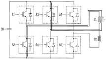
도 4a 및 도 4b를 참조하여, 인버터(40) 내의 스위칭 소자들(S1, S2, S3, S4)를 이용하여 제1 압축기(C1)의 운전을 제어하는 동작을 설명한다(S21). 제1 압축기(C1)는 인버터(40)의 스위칭 소자들(S1, S2, S3, S4)과 연결된다. 제어 유닛(50)이 압축기 운전 모드에 따라 제1 압축기만을 운전하도록 하는 제어 신호를 발생하면(S31), 제어 신호에 따라 상기 스위칭 소자들이 구동된다(S32). 도 4a를 참조하면, 제1 압축기의 +전류는 스위칭 소자들 S1과 S4에 의해서 흐른다. 한편, 도 4b를 참조하면, 제1 압축기의 -전류는 스위칭 소자들 S2와 S3에 의해서 흐른다. 도 5를 참조하면, 제2 압축기(C2)와 공통으로 연결되는 한 쌍의 스위칭 소자(S3, S4)에 대한 구동 신호는 운전 주파수(예를 들어, 60Hz)를 가진다. 한편, 다른 스위칭 소자들(S1, S2)에 대한 구동 신호는 제1 압축기에 대한 반송파 주파수(예를 들어, 3kHz)를 가진다.The operation of controlling the operation of the first compressor C1 using the switching elements S1, S2, S3, S4 in the
도 6a 및 도 6b를 참조하여, 인버터(40) 내의 스위칭 소자들(S3, S4, S5, S6)를 이용하여 제2 압축기(C2)의 운전을 제어하는 동작을 설명한다(S22). 제2 압축기(C2)는 인버터(40)의 스위칭 소자들(S3, S4, S5, S6)과 연결된다. 제어 유닛(50)이 압축기 운전 모드에 따라 제2 압축기만을 운전하도록 하는 제어 신호를 발생하면(S41), 제어 신호에 따라 상기 스위칭 소자들이 구동된다(S42). 도 6a를 참조하면, 제2 압축기의 +전류는 스위칭 소자들 S3과 S6에 의해서 흐른다. 한편, 도 6b을 참조하면, 제2 압축기의 -전류는 스위칭 소자들 S4와 S5에 의해서 흐른다. 도 7을 참조하면, 제1 압축기(C1)와 공통으로 연결되는 한 쌍의 스위칭 소자(S3, S4)에 대한 구동 신호는 운전 주파수(예를 들어, 60Hz)를 가진다. 한편, 다른 스위칭 소자들(S5, S6)은 제2 압축기에 대한 반송파 주파수(예를 들어, 3kHz)로 스위칭한다.An operation of controlling the operation of the second compressor C2 using the switching elements S3, S4, S5, and S6 in the
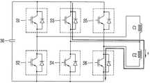
도 8a 내지 도 9b를 참조하여, 인버터 (40) 내의 스위칭 소자들(S1 내지 S6)를 이용하여 제1 압축기 및 제2 압축기의 운전을 제어하는 동작을 설명한다(S23). 제1 압축기(C1)의 +방향의 전류 제어는 스위칭 소자 S1로 수행하고(도 8a), 제2 압축기(C2)의 -방향의 전류 제어는 스위칭 소자 S5로 수행한다(도 8b). 이때, 공통 전류는 스위칭 소자 S4로 흐르게 된다. 한편, 제1 압축기(C1)의 -방향의 전류 제어는 스위칭 소자 S2로 수행하고(도 9b), 제2 압축기(C2)의 +방향의 전류 제어는 스위칭 소자 S6으로 수행한다(도 9a). 이때, 공통 전류는 스위칭 소자 S3으로 흐르게 된다. 즉, 도 8 및 도 9에 각각 도시한 바와 같이, 제1 압축기(C1)과 제2 압축기(C2)에 흐르는 전류 방향은 서로 반대이다. 도 10을 참조하면, 제1 압축기(C1) 및 제2 압축기(C2)에 공통으로 사용되는 한 쌍의 스위칭 소자(S3, S4)는 운전 주파수(예를 들어, 60Hz)로 스위칭하는 반면, 다른 스위칭 소자들(S1, S2, S5, S6)은 각각에 대한 반송파 주파수로 스위칭한다. 이때, 제1 및 제2 압축기에 대한 반송파 주파수는 동일할 수 있으나(예를 들어, 3kHz), 서로 다른 주파수(예를 들어, 제1 압축기에 대한 S1, S2에는 2kHz, 제2 압축기에 대한 S5, S6에는 3kHz)일 수 있다.The operation of controlling the operation of the first compressor and the second compressor using the switching elements S1 to S6 in the
이상 설명한 바와 같이, 본 발명의 실시 예들에 따른 압축기 제어 장치 및 이를 포함한 냉장고는, 하나의 인버터를 이용하여 두 대의 압축기의 운전을 제어함으로써 소자의 사용을 최소화하면서 압축기 용량을 확대하고 시스템의 운전 효율을 증대한다. 또, 본 발명의 실시 예들은 두 대의 압축기를 이용하여 부하나 냉력에 대응하여 복수의 운전 모드를 사용할 수 있다. 또, 본 발명은 하나의 인버터를 이용하여 두 대의 압축기를 개별 또는 동시 운전함으로써 시스템의 구성을 간소화하여 비용을 줄일 수 있다. 아울러, 본 발명의 실시 예들은 하나의 인버터를 이용하여 두 대의 압축기를 운전함에 있어서 공통으로 사용되는 스위칭 소자들을 다른 스위칭 소자들과 달리 운전 주파수로 스위칭함으로써 두 대의 압축기의 동시 운전을 가능하게 하고, 스위칭 손실을 저감하며, 시스템의 효율 및 안정성을 제고한다.As described above, the compressor control apparatus and the refrigerator including the same according to the embodiments of the present invention can control the operation of two compressors by using one inverter to expand the compressor capacity while minimizing the use of elements, . In the embodiments of the present invention, a plurality of operation modes may be used in correspondence to the cooling or the cooling by using two compressors. Further, the present invention simplifies the structure of the system by reducing the cost by operating two compressors individually or simultaneously using one inverter. In addition, embodiments of the present invention enable simultaneous operation of two compressors by switching switching elements commonly used in two compressors using one inverter to an operation frequency different from other switching elements, Reducing the switching loss, and improving the efficiency and stability of the system.
10: 상용 교류 전원20: 컨버터
30: 평활 유닛40: 인버터
50: 제어 유닛60: 부하 검출 유닛
70: 구동 유닛C1, C2: 제1, 제2 압축기10: Commercial AC power supply 20: Converter
30: smoothing unit 40: inverter
50: control unit 60: load detection unit
70: drive unit C1, C2: first and second compressors
Claims (12)
Translated fromKorean상기 제1 및 제2 압축기의 부하 상태에 따라 상기 구동 신호들로 구성된 인버터 제어 신호를 생성하여 상기 하나의 인버터에 출력하는 제어 유닛;을 포함하고,
상기 공통으로 연결되는 한 쌍의 스위칭 소자에 대한 구동 신호는, 다른 쌍의 스위칭 소자들에 대한 구동 신호들보다 느린 주파수를 가지는 것을 특징으로 하는 압축기 제어 장치.And a pair of switching elements of the three pairs of switching elements are connected in common to the first and second compressors and are switched according to the driving signals for the respective pairs of switching elements One inverter; And
And a control unit for generating an inverter control signal composed of the driving signals according to a load state of the first and second compressors and outputting the generated inverter control signal to the one inverter,
Wherein the driving signals for the pair of switching elements connected in common have a frequency that is slower than the driving signals for the other pair of switching elements.
상기 공통으로 연결되는 한 쌍의 스위칭 소자에 대한 구동 신호는 운전 주파수를 갖도록 하는 것을 특징으로 하는 압축기 제어 장치.The apparatus according to claim 1,
Wherein the driving signals for the pair of switching elements connected in common are set to have an operating frequency.
상용 교류 전원을 직류 전원으로 정류하는 컨버터;
상기 정류된 직류 전원을 평활화하고 저장하는 평활 유닛; 및
상기 인버터 제어 신호를 입력받아 상기 구동 신호들을 상기 하나의 인버터에 출력하는 구동 유닛;을 더 포함하는 압축기 제어 장치.3. The method of claim 2,
A converter for rectifying commercial AC power to DC power;
A smoothing unit for smoothing and storing the rectified DC power; And
And a drive unit for receiving the inverter control signal and outputting the drive signals to the one inverter.
상기 다른 쌍의 스위칭 소자들에 대한 구동 신호들은 각각 상기 제1 및 제2 압축기의 반송파 주파수를 갖도록 하는 것을 특징으로 하는 압축기 제어 장치.4. The apparatus according to claim 3,
And the driving signals for the other pair of switching elements have a carrier frequency of the first and second compressors, respectively.
상기 제1 및 제2 압축기를 각각 두 쌍의 스위칭 소자들에 연결하고, 상기 제1 및 제2 압축기를 동시 운전하거나, 또는 개별 운전하는 것을 특징으로 하는 압축기 제어 장치.5. The apparatus according to claim 4,
Wherein the first and second compressors are connected to two pairs of switching elements, respectively, and the first and second compressors are operated simultaneously or separately.
상기 제1 및 제2 압축기 내에 각각 구비된 제1 및 제2 모터에 인가되는 제1 및 제2 모터 구동 전류를 검출하는 제1 및 제2 전류 검출 유닛; 및
상기 제1 및 제2 모터에 인가되는 제1 및 제2 모터 구동 전압을 검출하는 제1 및 제2 전압 검출 유닛;을 더 포함하는 압축기 제어 장치.6. The method according to any one of claims 1 to 5,
First and second current detection units for detecting first and second motor drive currents applied to first and second motors respectively provided in the first and second compressors; And
And first and second voltage detection units for detecting first and second motor drive voltages applied to the first and second motors.
상기 제1 및 제2 모터 구동 전류와, 상기 제1 및 제2 모터 구동 전압을 이용하여 상기 제1 및 제2 압축기의 제1 및 제2 스트로크를 각각 연산하는 제1 및 제2 스트로크 연산 유닛;을 더 포함하는 압축기 제어 장치.The method according to claim 6,
First and second stroke operation units respectively operating the first and second strokes of the first and second compressors using the first and second motor drive currents and the first and second motor drive voltages; Further comprising:
상기 제1 및 제2 압축기의 각각에 대한 부하를 검출하는 제1 및 제2 부하 검출 유닛;을 더 포함하는 압축기 제어 장치.6. The method according to any one of claims 1 to 5,
And first and second load detection units for detecting loads on the first and second compressors, respectively.
상기 제1 압축기 또는 상기 제2 압축기는 리니어 압축기인 것을 특징으로 하는 압축기 제어 장치.6. The method according to any one of claims 1 to 5,
Wherein the first compressor or the second compressor is a linear compressor.
상기 냉장고 본체에 구비되고 냉매를 각각 압축하는 제1 및 제2 압축기;
세 쌍의 스위칭 소자들을 구비하고, 각 쌍의 스위칭 소자들에 대한 구동 신호들에 따라 스위칭하는 하나의 인버터;
상기 제1 및 제2 압축기의 부하를 검출하는 제1 및 제2 부하 검출 유닛; 및
상기 제1 및 제2 압축기의 부하 상태에 따라 상기 구동 신호들로 구성된 인버터 제어 신호를 생성하여 상기 하나의 인버터에 출력하는 제어 유닛;을 포함하고,
상기 하나의 인버터 내에 구비된 상기 세 쌍의 스위칭 소자들 중 한 쌍의 스위칭 소자는, 상기 제1 및 제2 압축기에 공통으로 연결되고 운전 주파수로 스위칭하는 것을 특징으로 하는 냉장고.Refrigerator body;
First and second compressors provided in the refrigerator main body and compressing the refrigerant, respectively;
One inverter having three pairs of switching elements, switching according to driving signals for each pair of switching elements;
First and second load detection units for detecting loads of the first and second compressors; And
And a control unit for generating an inverter control signal composed of the driving signals according to a load state of the first and second compressors and outputting the generated inverter control signal to the one inverter,
Wherein a pair of switching elements of the three pairs of switching elements provided in the one inverter is commonly connected to the first and second compressors and switches at an operating frequency.
상기 다른 쌍의 스위칭 소자들에 대한 구동 신호들은 각각 상기 제1 및 제2 압축기의 반송파 주파수를 갖도록 하는 것을 특징으로 하는 냉장고.11. The apparatus according to claim 10,
Wherein the driving signals for the other pair of switching elements each have a carrier frequency of the first and second compressors.
상용 교류 전원을 직류 전원으로 정류하는 컨버터;
상기 정류된 직류 전원을 평활화하고 저장하는 평활 유닛; 및
상기 인버터 제어 신호를 입력받아 상기 구동 신호들을 상기 하나의 인버터에 출력하는 구동 유닛;을 더 포함하는 냉장고.The method according to claim 10 or 11,
A converter for rectifying commercial AC power to DC power;
A smoothing unit for smoothing and storing the rectified DC power; And
And a driving unit for receiving the inverter control signal and outputting the driving signals to the one inverter.
Priority Applications (4)
| Application Number | Priority Date | Filing Date | Title |
|---|---|---|---|
| KR1020120009087AKR101772083B1 (en) | 2012-01-30 | 2012-01-30 | Apparatus for controlling compressor and refrigerator having the same |
| US13/752,578US9163621B2 (en) | 2012-01-30 | 2013-01-29 | Apparatus for controlling compressor and refrigerator having the same |
| EP13153059.4AEP2620722B1 (en) | 2012-01-30 | 2013-01-29 | Apparatus for controlling compressor and refrigerator having the same |
| CN201310036307.2ACN103225601B (en) | 2012-01-30 | 2013-01-30 | For controlling the device of compressor and there is the refrigerator of this device |
Applications Claiming Priority (1)
| Application Number | Priority Date | Filing Date | Title |
|---|---|---|---|
| KR1020120009087AKR101772083B1 (en) | 2012-01-30 | 2012-01-30 | Apparatus for controlling compressor and refrigerator having the same |
Publications (2)
| Publication Number | Publication Date |
|---|---|
| KR20130087864A KR20130087864A (en) | 2013-08-07 |
| KR101772083B1true KR101772083B1 (en) | 2017-08-28 |
Family
ID=47678594
Family Applications (1)
| Application Number | Title | Priority Date | Filing Date |
|---|---|---|---|
| KR1020120009087AActiveKR101772083B1 (en) | 2012-01-30 | 2012-01-30 | Apparatus for controlling compressor and refrigerator having the same |
Country Status (4)
| Country | Link |
|---|---|
| US (1) | US9163621B2 (en) |
| EP (1) | EP2620722B1 (en) |
| KR (1) | KR101772083B1 (en) |
| CN (1) | CN103225601B (en) |
Families Citing this family (6)
| Publication number | Priority date | Publication date | Assignee | Title |
|---|---|---|---|---|
| KR102181650B1 (en)* | 2013-10-04 | 2020-11-23 | 엘지전자 주식회사 | Inverter module for driving a plurality of compressors |
| KR102115247B1 (en)* | 2013-12-19 | 2020-05-26 | 엘지전자 주식회사 | Apparatus and method for controlling a linear compressor |
| US9518572B2 (en)* | 2014-02-10 | 2016-12-13 | Haier Us Appliance Solutions, Inc. | Linear compressor |
| WO2016110948A1 (en)* | 2015-01-07 | 2016-07-14 | 株式会社日立製作所 | Motor system and compressor |
| KR102138611B1 (en)* | 2019-07-11 | 2020-07-28 | 엘지전자 주식회사 | Apparatus for Driving Control of Reciprocating Compressor |
| US12398717B2 (en)* | 2023-02-09 | 2025-08-26 | Haier Us Appliance Solutions, Inc. | Single phase field oriented control for a linear compressor |
Citations (1)
| Publication number | Priority date | Publication date | Assignee | Title |
|---|---|---|---|---|
| JP2009050042A (en) | 2007-08-13 | 2009-03-05 | Yokohama National Univ | Switch inverter and control method for a plurality of three-phase loads |
Family Cites Families (18)
| Publication number | Priority date | Publication date | Assignee | Title |
|---|---|---|---|---|
| JPS57175858A (en)* | 1981-04-23 | 1982-10-28 | Mitsubishi Electric Corp | Air conditionor |
| MY122977A (en)* | 1995-03-14 | 2006-05-31 | Panasonic Corp | Refrigerating apparatus, and refrigerator control and brushless motor starter used in same |
| JP2000130824A (en)* | 1998-10-22 | 2000-05-12 | Mitsubishi Electric Corp | Control device for air conditioner |
| JP3871013B2 (en)* | 1998-11-05 | 2007-01-24 | 上村工業株式会社 | Tin-copper alloy electroplating bath and plating method using the same |
| JP2001016898A (en) | 1999-06-28 | 2001-01-19 | Denso Corp | Controller of ac motor |
| US6735968B2 (en)* | 2002-03-29 | 2004-05-18 | Hitachi, Ltd. | Refrigerating apparatus and an inverter device used therein |
| EP1843463B1 (en)* | 2002-12-12 | 2013-07-03 | Panasonic Corporation | Motor control apparatus |
| KR100556776B1 (en)* | 2003-11-26 | 2006-03-10 | 엘지전자 주식회사 | Operation Control System and Method of Reciprocating Compressor |
| US7793509B2 (en) | 2004-04-12 | 2010-09-14 | Johnson Controls Technology Company | System and method for capacity control in a multiple compressor chiller system |
| KR100565242B1 (en)* | 2004-05-21 | 2006-03-30 | 엘지전자 주식회사 | Control device and method of multi air conditioner for building |
| KR100677530B1 (en)* | 2004-11-26 | 2007-02-02 | 엘지전자 주식회사 | Operation Control System and Method of Reciprocating Compressor |
| KR100690663B1 (en)* | 2005-05-06 | 2007-03-09 | 엘지전자 주식회사 | Operation control device and method of variable displacement reciprocating compressor |
| KR100761268B1 (en) | 2006-01-06 | 2007-09-28 | 엘지전자 주식회사 | Operation Control System and Method of Reciprocating Compressor |
| JP2007303732A (en)* | 2006-05-11 | 2007-11-22 | Matsushita Electric Ind Co Ltd | Air conditioner |
| JP4192979B2 (en) | 2006-08-31 | 2008-12-10 | ダイキン工業株式会社 | Motor control device |
| US7895003B2 (en)* | 2007-10-05 | 2011-02-22 | Emerson Climate Technologies, Inc. | Vibration protection in a variable speed compressor |
| KR101372533B1 (en)* | 2007-11-20 | 2014-03-11 | 엘지전자 주식회사 | Motor controller of air conditioner |
| US8269438B2 (en) | 2009-08-07 | 2012-09-18 | Lg Electronics Inc. | Apparatus for driving motor of air conditioner and method for driving the same |
- 2012
- 2012-01-30KRKR1020120009087Apatent/KR101772083B1/enactiveActive
- 2013
- 2013-01-29EPEP13153059.4Apatent/EP2620722B1/enactiveActive
- 2013-01-29USUS13/752,578patent/US9163621B2/enactiveActive
- 2013-01-30CNCN201310036307.2Apatent/CN103225601B/enactiveActive
Patent Citations (1)
| Publication number | Priority date | Publication date | Assignee | Title |
|---|---|---|---|---|
| JP2009050042A (en) | 2007-08-13 | 2009-03-05 | Yokohama National Univ | Switch inverter and control method for a plurality of three-phase loads |
Also Published As
| Publication number | Publication date |
|---|---|
| EP2620722A2 (en) | 2013-07-31 |
| CN103225601B (en) | 2016-02-03 |
| EP2620722B1 (en) | 2019-04-24 |
| EP2620722A3 (en) | 2014-01-08 |
| CN103225601A (en) | 2013-07-31 |
| KR20130087864A (en) | 2013-08-07 |
| US9163621B2 (en) | 2015-10-20 |
| US20130195677A1 (en) | 2013-08-01 |
Similar Documents
| Publication | Publication Date | Title |
|---|---|---|
| KR101955977B1 (en) | Apparatus and method for controlling compressor, and refrigerator having the same | |
| KR101904870B1 (en) | Apparatus and method for controlling compressor, and refrigerator having the same | |
| KR101772083B1 (en) | Apparatus for controlling compressor and refrigerator having the same | |
| KR101214489B1 (en) | Apparatus for controlling compressor and method of the same | |
| KR100801359B1 (en) | Control device and control method of linear compressor | |
| KR20180087800A (en) | Apparatus for controlling linear compressor | |
| KR101299548B1 (en) | Apparatus for controlling compressor and method of the same | |
| CN103038510A (en) | Compressor control device, method, and refrigerator including the compressor control device | |
| KR101948563B1 (en) | Apparatus for controlling compressor and refrigerator having the same | |
| KR101852430B1 (en) | Apparatus and method for controlling compressor | |
| KR101718020B1 (en) | Apparatus for controlling linear compressor, method thereof, and refrigerator with the same | |
| KR102070277B1 (en) | Apparatus and method for controlling compressor | |
| KR101637441B1 (en) | Apparatus for controlling linear compressor, method thereof, and refrigerating system with the same | |
| KR102350512B1 (en) | Apparatus and method for controlling compressor | |
| KR101919886B1 (en) | Reciprocating compressor and apparatus for controlling compressor | |
| KR20180109262A (en) | Linear compressor and method for controlling linear compressor | |
| KR100588719B1 (en) | Control device and control method of linear compressor | |
| KR20130080282A (en) | Reciprocating compressor and apparatus for controlling compressor | |
| KR20190046543A (en) | Apparatus for controlling linear compressor and refrigerator including the same | |
| KR20130086504A (en) | Apparatus and method for controlling compressor |
Legal Events
| Date | Code | Title | Description |
|---|---|---|---|
| PA0109 | Patent application | St.27 status event code:A-0-1-A10-A12-nap-PA0109 | |
| PG1501 | Laying open of application | St.27 status event code:A-1-1-Q10-Q12-nap-PG1501 | |
| PN2301 | Change of applicant | St.27 status event code:A-3-3-R10-R13-asn-PN2301 St.27 status event code:A-3-3-R10-R11-asn-PN2301 | |
| A201 | Request for examination | ||
| PA0201 | Request for examination | St.27 status event code:A-1-2-D10-D11-exm-PA0201 | |
| D13-X000 | Search requested | St.27 status event code:A-1-2-D10-D13-srh-X000 | |
| D14-X000 | Search report completed | St.27 status event code:A-1-2-D10-D14-srh-X000 | |
| E701 | Decision to grant or registration of patent right | ||
| PE0701 | Decision of registration | St.27 status event code:A-1-2-D10-D22-exm-PE0701 | |
| GRNT | Written decision to grant | ||
| PR0701 | Registration of establishment | St.27 status event code:A-2-4-F10-F11-exm-PR0701 | |
| PR1002 | Payment of registration fee | St.27 status event code:A-2-2-U10-U11-oth-PR1002 Fee payment year number:1 | |
| PG1601 | Publication of registration | St.27 status event code:A-4-4-Q10-Q13-nap-PG1601 | |
| P22-X000 | Classification modified | St.27 status event code:A-4-4-P10-P22-nap-X000 | |
| PN2301 | Change of applicant | St.27 status event code:A-5-5-R10-R13-asn-PN2301 St.27 status event code:A-5-5-R10-R11-asn-PN2301 | |
| PR1001 | Payment of annual fee | St.27 status event code:A-4-4-U10-U11-oth-PR1001 Fee payment year number:4 | |
| PR1001 | Payment of annual fee | St.27 status event code:A-4-4-U10-U11-oth-PR1001 Fee payment year number:5 | |
| PR1001 | Payment of annual fee | St.27 status event code:A-4-4-U10-U11-oth-PR1001 Fee payment year number:6 | |
| PR1001 | Payment of annual fee | St.27 status event code:A-4-4-U10-U11-oth-PR1001 Fee payment year number:7 | |
| PR1001 | Payment of annual fee | St.27 status event code:A-4-4-U10-U11-oth-PR1001 Fee payment year number:8 | |
| L13-X000 | Limitation or reissue of ip right requested | St.27 status event code:A-2-3-L10-L13-lim-X000 | |
| PR1001 | Payment of annual fee | St.27 status event code:A-4-4-U10-U11-oth-PR1001 Fee payment year number:9 |