KR101771919B1 - Nanofiber filter including polyethylene terephthalate substrate and epoxy resin curing agent - Google Patents
Nanofiber filter including polyethylene terephthalate substrate and epoxy resin curing agentDownload PDFInfo
- Publication number
- KR101771919B1 KR101771919B1KR1020150165616AKR20150165616AKR101771919B1KR 101771919 B1KR101771919 B1KR 101771919B1KR 1020150165616 AKR1020150165616 AKR 1020150165616AKR 20150165616 AKR20150165616 AKR 20150165616AKR 101771919 B1KR101771919 B1KR 101771919B1
- Authority
- KR
- South Korea
- Prior art keywords
- nozzle
- solution
- epoxy resin
- electrospinning
- curing agent
- Prior art date
- Legal status (The legal status is an assumption and is not a legal conclusion. Google has not performed a legal analysis and makes no representation as to the accuracy of the status listed.)
- Expired - Fee Related
Links
Images


Classifications
- B—PERFORMING OPERATIONS; TRANSPORTING
- B01—PHYSICAL OR CHEMICAL PROCESSES OR APPARATUS IN GENERAL
- B01D—SEPARATION
- B01D39/00—Filtering material for liquid or gaseous fluids
- B01D39/14—Other self-supporting filtering material ; Other filtering material
- B01D39/16—Other self-supporting filtering material ; Other filtering material of organic material, e.g. synthetic fibres
- B01D39/1607—Other self-supporting filtering material ; Other filtering material of organic material, e.g. synthetic fibres the material being fibrous
- B01D39/1623—Other self-supporting filtering material ; Other filtering material of organic material, e.g. synthetic fibres the material being fibrous of synthetic origin
- B—PERFORMING OPERATIONS; TRANSPORTING
- B01—PHYSICAL OR CHEMICAL PROCESSES OR APPARATUS IN GENERAL
- B01D—SEPARATION
- B01D46/00—Filters or filtering processes specially modified for separating dispersed particles from gases or vapours
- B01D46/54—Particle separators, e.g. dust precipitators, using ultra-fine filter sheets or diaphragms
- B01D46/546—Particle separators, e.g. dust precipitators, using ultra-fine filter sheets or diaphragms using nano- or microfibres
- D—TEXTILES; PAPER
- D01—NATURAL OR MAN-MADE THREADS OR FIBRES; SPINNING
- D01D—MECHANICAL METHODS OR APPARATUS IN THE MANUFACTURE OF ARTIFICIAL FILAMENTS, THREADS, FIBRES, BRISTLES OR RIBBONS
- D01D5/00—Formation of filaments, threads, or the like
- D01D5/0007—Electro-spinning
- D01D5/0015—Electro-spinning characterised by the initial state of the material
- D01D5/0023—Electro-spinning characterised by the initial state of the material the material being a polymer melt
- D—TEXTILES; PAPER
- D01—NATURAL OR MAN-MADE THREADS OR FIBRES; SPINNING
- D01D—MECHANICAL METHODS OR APPARATUS IN THE MANUFACTURE OF ARTIFICIAL FILAMENTS, THREADS, FIBRES, BRISTLES OR RIBBONS
- D01D5/00—Formation of filaments, threads, or the like
- D01D5/0007—Electro-spinning
- D01D5/0061—Electro-spinning characterised by the electro-spinning apparatus
- D—TEXTILES; PAPER
- D04—BRAIDING; LACE-MAKING; KNITTING; TRIMMINGS; NON-WOVEN FABRICS
- D04H—MAKING TEXTILE FABRICS, e.g. FROM FIBRES OR FILAMENTARY MATERIAL; FABRICS MADE BY SUCH PROCESSES OR APPARATUS, e.g. FELTS, NON-WOVEN FABRICS; COTTON-WOOL; WADDING ; NON-WOVEN FABRICS FROM STAPLE FIBRES, FILAMENTS OR YARNS, BONDED WITH AT LEAST ONE WEB-LIKE MATERIAL DURING THEIR CONSOLIDATION
- D04H1/00—Non-woven fabrics formed wholly or mainly of staple fibres or like relatively short fibres
- D04H1/40—Non-woven fabrics formed wholly or mainly of staple fibres or like relatively short fibres from fleeces or layers composed of fibres without existing or potential cohesive properties
- D04H1/42—Non-woven fabrics formed wholly or mainly of staple fibres or like relatively short fibres from fleeces or layers composed of fibres without existing or potential cohesive properties characterised by the use of certain kinds of fibres insofar as this use has no preponderant influence on the consolidation of the fleece
- D04H1/4374—Non-woven fabrics formed wholly or mainly of staple fibres or like relatively short fibres from fleeces or layers composed of fibres without existing or potential cohesive properties characterised by the use of certain kinds of fibres insofar as this use has no preponderant influence on the consolidation of the fleece using different kinds of webs, e.g. by layering webs
- D—TEXTILES; PAPER
- D04—BRAIDING; LACE-MAKING; KNITTING; TRIMMINGS; NON-WOVEN FABRICS
- D04H—MAKING TEXTILE FABRICS, e.g. FROM FIBRES OR FILAMENTARY MATERIAL; FABRICS MADE BY SUCH PROCESSES OR APPARATUS, e.g. FELTS, NON-WOVEN FABRICS; COTTON-WOOL; WADDING ; NON-WOVEN FABRICS FROM STAPLE FIBRES, FILAMENTS OR YARNS, BONDED WITH AT LEAST ONE WEB-LIKE MATERIAL DURING THEIR CONSOLIDATION
- D04H1/00—Non-woven fabrics formed wholly or mainly of staple fibres or like relatively short fibres
- D04H1/70—Non-woven fabrics formed wholly or mainly of staple fibres or like relatively short fibres characterised by the method of forming fleeces or layers, e.g. reorientation of fibres
- D04H1/72—Non-woven fabrics formed wholly or mainly of staple fibres or like relatively short fibres characterised by the method of forming fleeces or layers, e.g. reorientation of fibres the fibres being randomly arranged
- D04H1/728—Non-woven fabrics formed wholly or mainly of staple fibres or like relatively short fibres characterised by the method of forming fleeces or layers, e.g. reorientation of fibres the fibres being randomly arranged by electro-spinning
- D—TEXTILES; PAPER
- D06—TREATMENT OF TEXTILES OR THE LIKE; LAUNDERING; FLEXIBLE MATERIALS NOT OTHERWISE PROVIDED FOR
- D06M—TREATMENT, NOT PROVIDED FOR ELSEWHERE IN CLASS D06, OF FIBRES, THREADS, YARNS, FABRICS, FEATHERS OR FIBROUS GOODS MADE FROM SUCH MATERIALS
- D06M15/00—Treating fibres, threads, yarns, fabrics, or fibrous goods made from such materials, with macromolecular compounds; Such treatment combined with mechanical treatment
- D06M15/19—Treating fibres, threads, yarns, fabrics, or fibrous goods made from such materials, with macromolecular compounds; Such treatment combined with mechanical treatment with synthetic macromolecular compounds
- D06M15/37—Macromolecular compounds obtained otherwise than by reactions only involving carbon-to-carbon unsaturated bonds
- D06M15/55—Epoxy resins
- F—MECHANICAL ENGINEERING; LIGHTING; HEATING; WEAPONS; BLASTING
- F02—COMBUSTION ENGINES; HOT-GAS OR COMBUSTION-PRODUCT ENGINE PLANTS
- F02C—GAS-TURBINE PLANTS; AIR INTAKES FOR JET-PROPULSION PLANTS; CONTROLLING FUEL SUPPLY IN AIR-BREATHING JET-PROPULSION PLANTS
- F02C7/00—Features, components parts, details or accessories, not provided for in, or of interest apart form groups F02C1/00 - F02C6/00; Air intakes for jet-propulsion plants
- F02C7/04—Air intakes for gas-turbine plants or jet-propulsion plants
- F02C7/05—Air intakes for gas-turbine plants or jet-propulsion plants having provisions for obviating the penetration of damaging objects or particles
- F02C7/052—Air intakes for gas-turbine plants or jet-propulsion plants having provisions for obviating the penetration of damaging objects or particles with dust-separation devices
- B—PERFORMING OPERATIONS; TRANSPORTING
- B01—PHYSICAL OR CHEMICAL PROCESSES OR APPARATUS IN GENERAL
- B01D—SEPARATION
- B01D2239/00—Aspects relating to filtering material for liquid or gaseous fluids
- B01D2239/02—Types of fibres, filaments or particles, self-supporting or supported materials
- B01D2239/025—Types of fibres, filaments or particles, self-supporting or supported materials comprising nanofibres
- B—PERFORMING OPERATIONS; TRANSPORTING
- B01—PHYSICAL OR CHEMICAL PROCESSES OR APPARATUS IN GENERAL
- B01D—SEPARATION
- B01D2239/00—Aspects relating to filtering material for liquid or gaseous fluids
- B01D2239/06—Filter cloth, e.g. knitted, woven non-woven; self-supported material
- B01D2239/0604—Arrangement of the fibres in the filtering material
- B01D2239/0631—Electro-spun
- D—TEXTILES; PAPER
- D10—INDEXING SCHEME ASSOCIATED WITH SUBLASSES OF SECTION D, RELATING TO TEXTILES
- D10B—INDEXING SCHEME ASSOCIATED WITH SUBLASSES OF SECTION D, RELATING TO TEXTILES
- D10B2505/00—Industrial
- D10B2505/04—Filters
Landscapes
- Engineering & Computer Science (AREA)
- Chemical & Material Sciences (AREA)
- Textile Engineering (AREA)
- Chemical Kinetics & Catalysis (AREA)
- Mechanical Engineering (AREA)
- Combustion & Propulsion (AREA)
- General Engineering & Computer Science (AREA)
- Nanotechnology (AREA)
- Spinning Methods And Devices For Manufacturing Artificial Fibers (AREA)
- Nonwoven Fabrics (AREA)
Abstract
Translated fromKoreanDescription
Translated fromKorean본 발명은 나노섬유를 포함하는 나노섬유 필터에 관한 것으로, 보다 상세하게는 폴리에틸렌테레프탈레이트 기재 및 에폭시 수지- 경화제를 포함하는 나노섬유 필터에 관한 것이다.The present invention relates to a nanofiber filter including nanofibers, and more particularly, to a nanofiber filter including a polyethylene terephthalate base and an epoxy resin-curing agent.
일반적으로, 화력발전소에서 사용하는 가스터빈은 외부로부터 정화된 공기를 흡입하여 압축한 뒤, 압축된 공기를 연료와 함께 연소기 내로 분사하여 혼합하고, 혼합된 공기와 연료를 연소시켜, 고온, 고압의 연소가스를 얻은 다음, 터빈의 베인에 분사하여 회전력을 얻는 회전식 내연기관의 일종이다. 이러한 가스터빈은 매우 정밀한 부품으로 구성되어 있기 때문에 주기적인 정비를 실시하며, 이 때 압축기로 유입되는 대기 중의 공기를 정화하기 위한 전처리용으로 에어필터를 사용한다.Generally, a gas turbine used in a thermal power plant sucks and compresses purified air from the outside, injects compressed air into the combustor together with the fuel, mixes the mixed air and fuel, It is a type of rotary internal combustion engine that obtains the combustion gas and then injects it into the vane of the turbine to obtain the rotational force. Because these gas turbines are made up of very precise parts, they are periodically serviced and use air filters for pretreatment to purify the air in the air entering the compressor.
에어필터는 가스터빈으로 흡입되는 연소용 공기를 대기 중에서 취할 때, 대기 중에 포함된 먼지, 분진 등의 이물질이 필터 여재 내로 침투하지 못하게 하여 정화된 공기를 공급할 수 있다. 그러나, 이물질의 크기가 큰 입자는 필터 여재 표면에 쌓이게 되어 필터 여재 표면에 필터 케이크(Filter Cake)를 형성할 뿐만 아니라, 미세한 입자는 필터 여재 내에 쌓이게 되어 필터 여재의 기공을 막는다. 결국, 입자들이 필터 여재의 표면에 쌓이게 되면 필터의 압력손실을 높이고, 수명을 저하시키는 문제가 있었다. The air filter is capable of supplying purified air by preventing foreign substances such as dust and dust contained in the air from permeating into the filter filter material when the combustion air sucked into the gas turbine is taken in the air. However, particles having a large particle size accumulate on the surface of the filter media, forming not only a filter cake on the surface of the filter media, but also accumulating fine particles in the filter media, thereby blocking the pores of the filter media. As a result, when the particles are accumulated on the surface of the filter media, there is a problem of increasing the pressure loss of the filter and decreasing the service life.
한편, 에어필터여재로서, 폴리테트라플루오로에틸렌 (이하, 「PTFE」라고 함) 의 다공막이 제안되고 있다 (예컨대, 일본 공개특허공보 평5-202217호 참조). 또, PTFE 다공막을 사용하는 경우는 막자체가 얇기 때문에 상처방지나 핀홀 발생방지를 위해, PTFE 다공막의 양면에, 심초 (core/sheath) 구조의 장섬유를 사용한 스판본드 부직포등의 열가소성 재료를 적층하여 보호하는 것도 제안되고 있다. (일본 공개특허공보 평6-218899호 참조) On the other hand, a porous membrane of polytetrafluoroethylene (hereinafter referred to as " PTFE ") has been proposed as an air filter medium (see, for example, Japanese Patent Application Laid-Open No. 5-202217). In the case of using a PTFE porous film, a thermoplastic material such as a spunbonded nonwoven fabric using long fibers of core / sheath structure is applied to both surfaces of the PTFE porous film in order to prevent scratches and pinholes from occurring because the film itself is thin It has also been proposed to laminate and protect it. (See Japanese Unexamined Patent Publication No. 6-218899)
그러나 종래의 에어필터는 이물질의 크기가 큰 입자는 필터 여재 표면에 쌓이게 되어 필터 여재 표면에 필터 케이크(Filter Cake)를 형성할 뿐만 아니라, 미세한 입자는 필터 여재 내에 쌓이게 되어 필터 여재의 기공을 막는다. 결국, 입자들이 필터 여재의 표면에 쌓이게 되면 필터의 압력손실을 높이고, 수명을 저하시키는 문제가 있었다.However, in the conventional air filter, particles having a large particle size accumulate on the surface of the filter material, so that the filter cake is formed on the surface of the filter material, and fine particles are accumulated in the filter material, thereby blocking the pores of the filter material. As a result, when the particles are accumulated on the surface of the filter media, there is a problem of increasing the pressure loss of the filter and decreasing the service life.
상기한 문제점을 해결하기 위하여 나노사이즈의 섬유를 제조하여 필터에 적용하는 다양한 방식들이 개발 및 사용되고 있다. 나노섬유를 필터에 적용할 경우, 직경이 큰 기존의 필터 여재에 비하여 비표면적이 크고, 표면 작용기에 대한 유연성도 좋다. 또한, 나노금의 가공사이즈를 갖으므로써 미세한 먼지입자의 효율적인 여과가 가능하다.In order to solve the above-mentioned problems, various methods of manufacturing nano-sized fibers and applying them to filters have been developed and used. When nanofibers are applied to a filter, the specific surface area is larger than that of a conventional filter material having a large diameter, and the flexibility of the surface functional group is also good. In addition, by having the processing size of nano gold, it is possible to efficiently filter fine dust particles.
그러나 종래의 나노섬유필터는 기재와 나노섬유 웹이 압착되도록 라미네이팅하는 라미네이팅 공정이 후공정으로 구비되어 있으나, 이 또한 기재와 고분자 방사용액의 재질 및 성분 차이에 의해 기재에서 고분자 방사용액이 전기방사되어 적층형성되는 나노섬유 웹이 탈리된다는 문제점이 있었다.However, in the conventional nanofiber filter, a laminating process for laminating the substrate and the nanofiber web is performed as a post-process. However, due to differences in materials and components of the substrate and the polymer solution, the polymer solution is electrospun There is a problem in that the nanofiber webs to be laminated are desorbed.
본 발명은 상기와 같은 문제점을 해결하기 위해 안출된 것으로, 방사구간을 적어도 2개 이상으로 구획하고, 구획된 적어도 2개 이상의 방사구간에 위치한 노즐블록에서 에폭시 수지 및 경화제를 연속적으로 전기방사하여 나노섬유 필터를 제조하고, 구획된 방사공간의 개수 또는 방사구간의 거리를 가변가능하여 요구되는 제품의 특성에 적합한 나노섬유 필터의 제조가 가능하며, 제조 공정을 간소화하여 전체 비용을 감소시킬 수 있는 나노섬유 필터를 제공하는 것을 목적으로 한다.Disclosure of the Invention The present invention has been conceived to solve the problems as described above, and it is an object of the present invention to provide a method of manufacturing a semiconductor device, which comprises a step of dividing a radiation section into at least two or more and continuously spraying an epoxy resin and a curing agent in a nozzle block, A fiber filter is manufactured and the number of the divided radiation spaces or the distance of the radiation section can be varied to manufacture a nanofiber filter suited to a desired product characteristic and a manufacturing process can be simplified, It is an object of the present invention to provide a fiber filter.
본 발명은 폴리에틸렌테레프탈레이트 기재; 상기 폴리에틸렌테레프탈레이트 기재 상에 에폭시 수지 용액을 전기방사하여 형성되는 제1나노섬유층; 상기 제1나노섬유층 상에 경화제 용액을 전기방사하여 적층형성되는 제2나노섬유층; 및 상기 제 2나노섬유층 상에 에폭시 수지 용액을 전기방사하여 형성되는 제 3나노섬유층을 포함하는 나노섬유 필터를 제공한다.The present invention relates to a polyethylene terephthalate substrate; A first nanofiber layer formed by electrospinning an epoxy resin solution on the polyethylene terephthalate substrate; A second nanofiber layer laminated by electrospinning a curing agent solution on the first nanofiber layer; And a third nanofiber layer formed by electrospinning an epoxy resin solution on the second nanofiber layer.
또한 본 발명은 상기 에폭시 수지 용액 및 경화제 용액은 온도조절 장치를 통하여 50 내지 100℃의 온도에서 전기방사되는 것을 특징으로 하는 나노섬유 필터를 제공한다.The present invention also provides a nanofiber filter characterized in that the epoxy resin solution and the curing agent solution are electrospun through a temperature controller at a temperature of 50 to 100 ° C.
여기서, 상기 온도조절 장치를 통하여 에폭시 수지 용액 및 경화제 용액의 점도는 1,000 내지 3,000cps로 조절되는 것을 특징으로 하는 나노섬유 필터를 제공한다.Here, the viscosity of the epoxy resin solution and the curing agent solution is controlled to 1,000 to 3,000 cps through the temperature controller.
이에 더해, 본 발명은 상기 제1 나노섬유층, 제2 나노섬유층 및 제3 나노섬유층은 종방향 또는 횡방향을 따라 평량이 상이한 것을 특징으로 하는 나노섬유 필터를 제공한다.In addition, the present invention provides a nanofiber filter wherein the first nanofiber layer, the second nanofiber layer, and the third nanofiber layer are different in basis weight along the longitudinal direction or the transverse direction.
본 발명에 따른 나노섬유 필터의 제조방법은 적어도 2개 이상의 방사구간으로 구획되고, 각 방사구간을 통하여 에폭시 수지 및 경화제를 연속적으로 전기방사하여 2층 이상으로 적층형성되는 나노섬유 필터를 얻음으로써, 나노섬유 필터의 제조공정을 단순화 및 간소화할 수 있으며, 이로 인하여 제조비용 및 제조시간을 절감시킬 수 있다는 경제적인 이점이 있다.The method of manufacturing a nanofiber filter according to the present invention comprises a nanofiber filter which is divided into at least two radiation sections and is continuously electrospun epoxy resin and a curing agent through each radiation section to form a laminate of two or more layers, The manufacturing process of the nanofiber filter can be simplified and simplified, thereby reducing the manufacturing cost and manufacturing time.
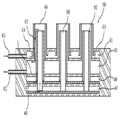
도 1은 본 발명에 의한 전기방사장치를 개략적으로 나타내는 측면도,
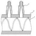
도 2는 본 발명에 의한 전기방사장치의 각 유닛 내에 설치되는 노즐블록의 노즐을 개략적으로 나타내는 측단면도,
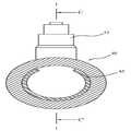
도 3은 본 발명에 의한 전기방사장치의 각 유닛 내에 설치되는 노즐블록의 노즐에 따른 다른 실시예를 개략적으로 나타내는 측단면도,
도 4는 본 발명에 의한 전기방사장치의 각 유닛 내에 설치되는 노즐블록을 개략적으로 나타내는 평면도,
도 5는 본 발명에 의한 전기방사장치의 각 유닛 내에 설치되는 노즐블록에 전열장치가 설치된 모습을 개략적으로 나타내는 정단면도,
도 6은 A-A'선 단면도,
도 7은 본 발명에 의한 전기방사장치의 각 유닛 내에 설치되는 노즐블록에 전열장치가 설치된 모습의 다른 실시예를 개략적으로 나타내는 정단면도,
도 8은 B-B'선 단면도,
도 9는 본 발명에 의한 전기방사장치의 각 유닛 내에 설치되는 노즐블록에 전열장치가 설치된 모습의 또 다른 실시예를 개략적으로 나타내는 정단면도,
도 10은 C-C'선 단면도,
도 11은 본 발명에 의한 전기방사장치의 보조 이송장치를 개략적으로 나타내는 도면,
도 12는 본 발명에 의한 전기방사장치의 보조 이송장치의 보조벨트 롤러의 다른 실시예를 개략적으로 나타내는 도면,
도 13 내지 도 16은 본 발명에 의한 전기방사장치의 장척시트 이송속도 조절장치의 동작과정을 개략적으로 나타내는 측면도,
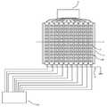
도 17은 본 발명에 의한 전기방사장치의 노즐블록에 배열 설치되는 노즐관체에 따른 다른 실시예를 개략적으로 나타내는 평면도,
도 18은 본 발명에 의한 전기방사장치의 노즐블록에 배열 설치되는 노즐관체에 따른 다른 실시예를 개략적으로 나타내는 사시도,
도 19는 본 발명에 의한 전기방사장치의 노즐블록에 배열 설치되는 노즐관체에 따른 다른 실시예를 개략적으로 나타내는 측면도,
도 20 및 도 21은 본 발명에 의한 전기방사장치의 각 노즐관체의 노즐을 통하여 에폭시 수지 및 경화제가 기재의 동일 평면 상에 전기방사되는 동작과정(도 20에서 파선으로 표시된 노즐이 폐쇄된 노즐을 나타내고, 도 21에서 파선으로 표시된 노즐은 기재 하부에 위치하는 것을 나타냄)에 따른 다른 실시예를 개략적으로 나타내는 평면도,
도 22은 본 발명에 의한 전기방사장치의 노즐블록에 배열 설치되는 노즐관체에 따른 또 다른 실시예를 개략적으로 나타내는 평면도,
도 23는 본 발명에 의한 전기방사장치의 노즐블록에 배열 설치되는 노즐관체에 따른 또 다른 실시예를 개략적으로 나타내는 사시도,
도 24 및 도 25은 본 발명에 의한 전기방사장치의 각 노즐관체의 노즐을 통하여 에폭시 수지 및 경화제가 기재의 동일 평면 상에 전기방사되는 동작과정 따른 또 다른 실시예를 개략적으로 나타내는 평면도,
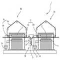
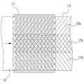
도 26은 본 발명의 폴리에틸렌테레프탈레이트 기재, 에폭시 수지 나노섬유 및 경화제 나노섬유를 포함하는 나노섬유 필터를 나타내는 모식도.1 is a side view schematically showing an electrospinning apparatus according to the present invention,
2 is a side sectional view schematically showing a nozzle of a nozzle block installed in each unit of the electrospinning apparatus according to the present invention,
3 is a side cross-sectional view schematically showing another embodiment according to a nozzle of a nozzle block installed in each unit of the electrospinning apparatus according to the present invention,
4 is a plan view schematically showing a nozzle block installed in each unit of the electrospinning apparatus according to the present invention,
5 is a front sectional view schematically showing a state in which an electric heater is installed in a nozzle block installed in each unit of the electrospinning apparatus according to the present invention,
6 is a sectional view taken along line A-A '
7 is a front sectional view schematically showing another embodiment in which an electric heater is installed in a nozzle block installed in each unit of the electrospinning apparatus according to the present invention,
8 is a sectional view taken along the line B-B '
Fig. 9 is a front sectional view schematically showing another embodiment of a state in which an electric heater is installed in a nozzle block installed in each unit of the electrospinning apparatus according to the present invention, Fig.
10 is a sectional view taken along line C-C '
11 is a view schematically showing an auxiliary transfer device of an electrospinning device according to the present invention,
12 is a view schematically showing another embodiment of the auxiliary belt roller of the auxiliary transfer device of the electrospinning apparatus according to the present invention,
FIG. 13 to FIG. 16 are side views schematically showing the operation of the long sheet conveying speed adjusting apparatus of the electrospinning apparatus according to the present invention,
17 is a plan view schematically showing another embodiment according to the nozzle body arranged in the nozzle block of the electrospinning apparatus according to the present invention,
18 is a perspective view schematically showing another embodiment according to the nozzle body arranged in the nozzle block of the electrospinning apparatus according to the present invention,
19 is a side view schematically showing another embodiment according to a nozzle body arranged in a nozzle block of the electrospinning apparatus according to the present invention,
20 and 21 show an operation process (in FIG. 20, a nozzle in which a nozzle indicated by a broken line is closed in FIG. 20) is irradiated through a nozzle of each nozzle tube of the electrospinning apparatus according to the present invention, And the nozzle indicated by the broken line in Fig. 21 is located at the lower portion of the substrate), which is a plan view schematically showing another embodiment,
22 is a plan view schematically showing another embodiment according to a nozzle body arranged in a nozzle block of the electrospinning apparatus according to the present invention,
23 is a perspective view schematically showing another embodiment according to the nozzle body arranged in the nozzle block of the electrospinning apparatus according to the present invention,
FIG. 24 and FIG. 25 are plan views schematically showing another embodiment according to an operation process of electrospinning the epoxy resin and the curing agent on the same plane of the substrate through the nozzles of each nozzle tube of the electrospinning apparatus according to the present invention,
26 is a schematic diagram showing a nanofiber filter comprising a polyethylene terephthalate base material, an epoxy resin nanofiber, and a curing agent nanofiber according to the present invention.
이하, 본 발명에 대하여 설명한다.Hereinafter, the present invention will be described.
본 실시예에서는 본 발명의 권리범위를 한정하는 것은 아니고, 단지 예시로 제시한 것이며, 그 기술적인 요지를 이탈하지 않는 범위 내에서 다양한 변경이 가능하다.The present invention is not limited to the scope of the present invention, but is merely an example, and various modifications can be made without departing from the technical gist of the present invention.
본 발명은 폴리에틸렌테레프탈레이트 기재 상에 에폭시 수지를 전기방사하여 형성되는 제 1나노섬유층; 상기 제 1나노섬유층 상에 경화제 용액을 전기방사하여 적층형성되는 제 2나노섬유층; 및 상기 제 2나노섬유층 상에 에폭시 수지를 전기방사하여 형성되는 제 3나노섬유층을 포함하는 나노섬유 필터를 제공한다.The present invention relates to: a first nanofiber layer formed by electrospinning an epoxy resin on a polyethylene terephthalate substrate; A second nanofiber layer laminated by electrospinning a curing agent solution on the first nanofiber layer; And a third nanofiber layer formed by electrospinning an epoxy resin on the second nanofiber layer.
이때, 상기 에폭시(epoxy) 수지는 열경화성 수지의 중간체로 경화제와의 반응에 의하여 불용/불융의 3차원 망목상 구조를 형성하여 에폭시 고유의 물성을 나타내며, 상기 에폭시 수지는 경화제와의 반응에 의하여 접착성, 기계적 강도, 내열성, 내화학성, 내수성, 전기 절연성, 성형성 및 함침성이 우수해지며, 복합재료의 제조가 용이하며, 경화제의 선택에 따라 다양한 물성의 구현이 가능한 장점이 있다.At this time, the epoxy resin is an intermediate of a thermosetting resin and forms a three-dimensional network structure insoluble / infusible by reaction with a curing agent to exhibit physical properties inherent to epoxy, and the epoxy resin is adhered It has an advantage of being excellent in properties, mechanical strength, heat resistance, chemical resistance, water resistance, electric insulation property, moldability and impregnation property, easy production of a composite material, and realizing various properties according to the selection of a curing agent.
이러한 에폭시 수지의 비제한적인 예를 들면, 비스페놀 A형 에폭시 수지, 비스페놀 F형 에폭시 수지, 비스페놀 S형 에폭시 수지 등이 있다.Nonlimiting examples of such epoxy resins include bisphenol A type epoxy resins, bisphenol F type epoxy resins, and bisphenol S type epoxy resins.
상기 비스페놀 A형 에폭시 수지는 하기 화학식 1로 나타내며, 가장 일반적으로 사용되는 에폭시 수지로써 제법이 크게 직접법과 간접법이 있다.The above-mentioned bisphenol A type epoxy resin is represented by the following general formula (1), and the most commonly used epoxy resin is produced by a direct method or indirect method.
[화학식 1][Chemical Formula 1]

또한, 상기 비스페놀 F형 에폭시 수지는 하기 화학식 2로 표시되고, 비스페놀 F와 ECH 반응으로 만들어지며, 비스페놀 A형 에폭시 수지와 비교시 점도가 낮으며, 이론상 기계적, 물리적 특성이 다소 떨어지나, 오히려 일반적인 접착 등에서 향상되는 특성을 나타낸다.The bisphenol F type epoxy resin is represented by the following general formula (2) and is produced by the reaction of bisphenol F with ECH. The bisphenol F type epoxy resin has a lower viscosity than the bisphenol A type epoxy resin and theoretically has a somewhat lower mechanical and physical properties. And the like.
[화학식 2](2)

또한, 상기 비스페놀 S형 에폭시 수지는 하기 화학식 3으로 표시되고, 일반적으로 에폭시 접착제를 빠르게 경화시키는데 사용되며, 중합체 반응에서 반응물로서 사용된다.The bisphenol S type epoxy resin is represented by the following general formula (3), and is generally used for rapidly curing an epoxy adhesive and used as a reactant in a polymer reaction.
[화학식 3](3)

한편, 상기 경화제는 아민계 경화제, 산무수물계 경화제 및 이미다졸계 경화제로 이루어진 군에서 선택된 1종인 것이 바람직하나, 이에 한정되는 것은 아니다.On the other hand, the curing agent is preferably one selected from the group consisting of an amine curing agent, an acid anhydride curing agent and an imidazole curing agent, but is not limited thereto.
상기 아민계 경화제의 비제한적인 예로는, 지방족 폴리아민, 변성 지방족 폴리아민, 방향족 아민, 3차 아민, 2차 아민 등이 있다.Non-limiting examples of the amine-based curing agent include aliphatic polyamines, modified aliphatic polyamines, aromatic amines, tertiary amines, and secondary amines.
상기 지방족 폴리아민의 예로는, Diethylene Triamine (DETA), Triethylene Tetramine (TETA), Diethylamino propyl amine (DEAPA), Menthane diamine(MDA), N-aminoethyl piperazine (N-AEP), M-xylene diamine (MXDA), Isophorone diamine (IPDA) 등이 있으나, 이에 한정되는 것은 아니다.Examples of the aliphatic polyamines include diethylene triamine (DETA), triethylene tetramine (TETA), diethylamino propyl amine (DEAPA), Menthane diamine (MDA), N-aminoethyl piperazine Isophorone diamine (IPDA), but is not limited thereto.
상기 변성 지방족 폴리아민의 예로는, Epoxy Polyamine Adduct, Ethylene 또는 Propylene Oxide 와 Polyamine adduct, Cyanoethyl화 Polyamine, Ketone 봉쇄 Polyamine (Ketimine) 등이 있으나, 이에 한정되는 것은 아니다.Examples of the modified aliphatic polyamines include, but are not limited to, Epoxy Polyamine Adduct, Ethylene or Propylene Oxide, Polyamine adduct, Cyanoethylated Polyamine, and Ketone blocked Polyamine (Ketimine).
상기 방향족 아민의 예로는, Meta phenylene Diamine (MPD), 4.4' Dimethyl aniline (DAM or DDM), Diamino Diphenyl Sulfone (DDS), Aromatic amine adduct 등이 있으나, 이에 한정되는 것은 아니다.Examples of the aromatic amine include Meta phenylene Diamine (MPD), 4.4 'Dimethyl aniline (DAM or DDM), Diamino Diphenyl Sulfone (DDS), and Aromatic amine adduct.
또한, 상기 산무수물계 경화제의 비제한적인 예로는, 폴리아미드(PA), 4수소무수프탈산(THPA), 메틸4수소무수프탈산(MTHPA), 6수소무수프탈산(HHPA), MNA 등이 있다.Examples of the acid anhydride-based curing agent include polyamide (PA), tetrahydrophthalic anhydride (THPA), methyl tetrahydrophthalic anhydride (MTHPA), hexahydrophthalic anhydride (HHPA), and MNA.
또한, 이미다졸계 경화제의 비제한적인 예로는, 2MZ, 2E4MZ 등이 있다.Nonlimiting examples of the imidazole-based curing agent include 2MZ and 2E4MZ.
또한, 상기 경화제 용액은 경화촉진제를 추가로 더 포함할 수 있다.In addition, the curing agent solution may further include a curing accelerator.
본 발명에 있어서 사용되는 경화 촉진제로서는 에폭시 화합물의 경화 촉진에 일반적으로 사용되는 경화 촉진제이면 특별히 제한은 없고, 예를 들면 제3급 아민, 제3급 아민염, 이미다졸류, 유기 인계 화합물, 제4급 암모늄염, 제4급 포스포늄염, 유기 금속염, 붕소 화합물 등을 이용할 수 있다. 경화 촉진제는 1종 단독으로 또는 2종 이상을 조합하여 사용할 수 있다.The curing accelerator used in the present invention is not particularly limited as long as it is a curing accelerator generally used for accelerating the curing of the epoxy compound. Examples thereof include tertiary amines, tertiary amine salts, imidazoles, Quaternary ammonium salts, quaternary phosphonium salts, organic metal salts, and boron compounds. The curing accelerator may be used alone or in combination of two or more.
제3급 아민으로서는 예를 들면 라우릴디메틸아미노, N,N-디메틸시클로헥실아민, N,N-디메틸벤질아민, N,N-디메틸아닐린, (N,N-디메틸아미노메틸)페놀, 2,4,6-트리스(N,N-디메틸아미노메틸)페놀, 1,8-디아자비시클로[5.4.0]운데센-7(DBU), 1,5-디아자비시클로[4.3.0]노넨-5(DBN) 등을 들 수 있다.Examples of tertiary amines include lauryldimethylamino, N, N-dimethylcyclohexylamine, N, N-dimethylbenzylamine, N, N-dimethylaniline, (N, N- dimethylaminomethyl) (N, N-dimethylaminomethyl) phenol, 1,8-diazabicyclo [5.4.0] undecene-7 (DBU), 1,5-diazabicyclo [4.3.0] 5 (DBN).
제3급 아민염으로서는 예를 들면 상기 제3급 아민의 카르복실산염, 술폰산염, 무기산염 등을 들 수 있다. 카르복실산염으로서는 옥틸산염 등의 탄소수 1 내지 30(특히, 탄소수 1 내지 10)의 카르복실산의 염(특히, 지방산의염) 등을 들 수 있다. 술폰산염으로서는 p-톨루엔술폰산염, 벤젠술폰산염, 메탄술폰산염, 에탄술폰산염 등을 들 수 있다. 제3급 아민염의 대표적인 예로서 1,8-디아자비시클로[5.4.0]운데센-7(DBU)의 염(예를 들면, p-톨루엔술폰산염, 옥틸산염) 등을 들 수 있다.Examples of the tertiary amine salt include a carboxylate, a sulfonate, and an inorganic acid salt of the above-mentioned tertiary amine. Examples of the carboxylate include salts of carboxylic acids having 1 to 30 carbon atoms (especially 1 to 10 carbon atoms) such as octylate (particularly fatty acid salts). Examples of the sulfonic acid salt include p-toluenesulfonic acid salt, benzenesulfonic acid salt, methanesulfonic acid salt and ethanesulfonic acid salt. Representative examples of tertiary amine salts include salts of 1,8-diazabicyclo [5.4.0] undecene-7 (DBU) (for example, p-toluenesulfonic acid salt and octylic acid salt).
금속계 경화 촉진제로서는, 코발트, 구리, 아연, 철, 니켈, 망간, 주석 등의 금속의, 유기 금속 착체 또는 유기 금속염을 들 수 있다. 유기 금속 착체의 구체예로서는, 코발트(II) 아세틸아세토네이트, 코발트(III) 아세틸아세토네이트 등의 유기 코발트 착체, 구리(II) 아세틸아세토네이트 등의 유기 구리 착체, 아연(II) 아세틸아세토네이트 등의 유기 아연 착체, 철(III) 아세틸아세토네이트 등의 유기 철 착체, 니켈(II) 아세틸아세토네이트 등의 유기 니켈 착체, 망간(II) 아세틸아세토네이트 등의 유기 망간 착체 등을 들 수 있다. 유기 금속염으로서는, 옥틸산아연, 옥틸산주석, 나프텐산아연, 나프텐산코발트, 스테아르산주석, 스테아르산아연 등을 들 수 있다. 금속계 경화 촉진제로서는, 경화성, 용제 용해성의 관점에서, 코발트(II) 아세틸아세토네이트, 코발트(III) 아세틸아세토네이트, 아연(II) 아세틸아세토네이트, 나프텐산아연, 철(III) 아세틸아세토네이트가 바람직하고, 특히 코발트(II) 아세틸아세토네이트, 나프텐산아연이 바람직하다. 금속계 경화 촉진제는 1종 또는 2종 이상을 조합하여 사용해도 양호하다.Examples of the metal-based curing accelerator include organic metal complexes or organic metal salts of metals such as cobalt, copper, zinc, iron, nickel, manganese and tin. Specific examples of the organometallic complexes include organic cobalt complexes such as cobalt (II) acetylacetonate and cobalt (III) acetylacetonate, organic copper complexes such as copper (II) acetylacetonate, zinc An organic iron complex such as an organic zinc complex and iron (III) acetylacetonate, an organic nickel complex such as nickel (II) acetylacetonate, and an organic manganese complex such as manganese (II) acetylacetonate. Examples of the organic metal salt include zinc octylate, tin octylate, zinc naphthenate, cobalt naphthenate, stannous stearate and zinc stearate. As the metal curing accelerator, cobalt (II) acetylacetonate, cobalt (III) acetylacetonate, zinc (II) acetylacetonate, zinc naphthenate and iron (III) acetylacetonate are preferable from the viewpoints of curability and solvent solubility And particularly, cobalt (II) acetylacetonate and zinc naphthenate are preferable. The metal-based curing accelerator may be used singly or in combination of two or more.
금속계 경화 촉진제의 첨가량은, 수지 조성물 중의 불휘발분을 100질량%로 한 경우, 금속계 경화 촉진제에 기초하는 금속의 함유량이 25 내지 500ppm, 보다 바람직하게는 40 내지 200ppm이 되는 범위에서 첨가하는 것이 바람직하다. 25ppm 미만이면, 저 조도(粗度)의 절연층 표면으로의 밀착성이 우수한 도체층의 형성이 곤란해지는 경향이 있으며, 500ppm을 초과하면, 수지 조성물의 보존 안정성, 절연성이 저하되는 경향으로 된다. The addition amount of the metal-based curing accelerator is preferably in the range of from 25 to 500 ppm, more preferably from 40 to 200 ppm, of the metal based on the metal-based curing accelerator when the non-volatile content in the resin composition is 100 mass% . If it is less than 25 ppm, it tends to make it difficult to form a conductor layer having a low roughness with good adhesion to the surface of the insulating layer. When it exceeds 500 ppm, the storage stability and insulating property of the resin composition tend to be lowered.
제4급 암모늄염으로서는 예를 들면 테트라에틸암모늄브로미드, 테트라부틸암모늄브로미드 등을 들 수 있다.Examples of the quaternary ammonium salt include tetraethylammonium bromide and tetrabutylammonium bromide.
제4급 포스포늄염으로서는 예를 들면 하기 식 (1) As the quaternary phosphonium salt, for example, the following formula (1)

(식중, R1, R2, R3, R4 는 동일 또는 상이하며, 탄소수 1 내지 16의 탄화수소기를 나타내고, X는 카르복실산 또는 유기 술폰산의 음이온 잔기를 나타냄)로 표시되는 화합물 등을 들 수 있다.(Wherein R1, R2, R3 and R4 are the same or different and each represents a hydrocarbon group of 1 to 16 carbon atoms, and X represents an anion residue of a carboxylic acid or an organic sulfonic acid).
상기 탄소수 1 내지 16의 탄화수소기로서는 예를 들면 메틸, 에틸, 프로필, 이소프로필, 부틸, 이소부틸, s-부틸, t-부틸, 펜틸, 헥실, 옥틸, 데실, 도데실기 등의 직쇄상 또는 분지쇄상의 알킬기; 비닐, 알릴, 크로틸기 등의 직쇄상 또는 분지쇄상의 알케닐기; 페닐, 톨루일, 크실릴, 나프틸, 안트릴, 페난트릴기 등의 아릴기; 벤질, 페네틸기 등의 아랄킬기 등을 들 수 있다. 이들 중에서도 탄소수 1 내지 6의 직쇄상 또는 분지쇄상의 알킬기, 특히 부틸기가 바람직하다. Examples of the hydrocarbon group having 1 to 16 carbon atoms include a linear or branched hydrocarbon group such as methyl, ethyl, propyl, isopropyl, butyl, isobutyl, s-butyl, t-butyl, pentyl, A straight chain alkyl group; Straight or branched alkenyl groups such as vinyl, allyl, and crotyl; Aryl groups such as phenyl, toluyl, xylyl, naphthyl, anthryl, phenanthryl groups; And aralkyl groups such as benzyl and phenethyl groups. Of these, a straight or branched alkyl group having 1 to 6 carbon atoms, particularly a butyl group, is preferred.
상기 「카르복실산 또는 유기 술폰산의 음이온 잔기」에 있어서의 「카르복실산」으로서는, 예를 들면 옥탄산, 데칸산, 라우르산, 미리스트산, 팔미트산 등의 탄소수 1 내지 20의 지방족 모노 카르복실산; 1,2,4,5-시클로헥산테트라카르복실산, 비시클로[2.2.1]헵탄-2,3-디카르복실산, 메틸비시클로[2.2.1]헵탄-2,3-디카르복실산 등의 지환식 카르복실산(단환의 지환식 모노 또는 폴리카르복실산, 가교환식 모노 또는 폴리카르복실산) 등을 들 수있다. 또한, 지환식 카르복실산의 지환에는 메틸기 등의 탄소수 1 내지 4의 직쇄상 또는 분지쇄상 알킬기, 메톡시기 등의 탄소수 1 내지 4의 알콕시기, 염소 원자 등의 할로겐 원자 등의 치환기가 결합하고 있을 수도 있다. 상기 카르복실산으로서는 그 중에서도 탄소수 10 내지 18의 지방족 모노 카르복실산, 탄소수 8 내지 18의 지환식 폴리카르복실산이 바람직하다. Examples of the "carboxylic acid" in the "anion residue of a carboxylic acid or an organic sulfonic acid" include aliphatic alcohols having 1 to 20 carbon atoms such as octanoic acid, decanoic acid, lauric acid, myristic acid and palmitic acid Monocarboxylic acids; 1,2,4,5-cyclohexanetetracarboxylic acid, bicyclo [2.2.1] heptane-2,3-dicarboxylic acid, methylbicyclo [2.2.1] heptane-2,3-dicarboxylate Alicyclic carboxylic acids (monocyclic alicyclic mono- or polycarboxylic acids, crosslinked cyclic mono- or polycarboxylic acids), and the like. The alicyclic carboxylic acid may have a substituent such as a linear or branched alkyl group having 1 to 4 carbon atoms such as a methyl group, an alkoxy group having 1 to 4 carbon atoms such as a methoxy group, or a halogen atom such as a chlorine atom It is possible. As the carboxylic acid, an aliphatic monocarboxylic acid having a carbon number of 10 to 18 and an alicyclic polycarboxylic acid having a carbon number of 8 to 18 are preferable.
상기 「카르복실산 또는 유기 술폰산의 음이온 잔기」에 있어서의 「유기 술폰산」으로서는, 예를 들면 메탄술폰산, 에탄술폰산, 1-프로판술폰산, 2-프로판술폰산, 1-부탄술폰산, 1-펜탄술폰산, 1-헥산술폰산, 1-옥탄술폰산, 1-데칸술폰산, 1-도데칸술폰산 등의 지방족 술폰산(예를 들면, 탄소수 1 내지 16의 지방족 술폰산 등); 벤젠술폰산, p-톨루엔술폰산, 4-에틸벤젠술폰산, 3-(직쇄상 또는 분지쇄상 옥틸)벤젠술폰산, 4-(직쇄상또는 분지쇄상 옥틸)벤젠술폰산, 3-(직쇄상 또는 분지쇄상 도데실)벤젠술폰산, 4-(직쇄상 또는 분지쇄상도데실)벤젠술폰산, 2,4-디메틸벤젠술폰산, 2,5-디메틸벤젠술폰산, 4-메톡시벤젠술폰산, 4-에톡시벤젠술폰산, 4-클로로벤젠술폰산 등을 들 수 있다.Examples of the "organic sulfonic acid" in the above "anionic residue of a carboxylic acid or an organic sulfonic acid" include methanesulfonic acid, ethanesulfonic acid, 1-propanesulfonic acid, 2-propanesulfonic acid, 1-butanesulfonic acid, Aliphatic sulfonic acids such as 1-hexanesulfonic acid, 1-octanesulfonic acid, 1-decanesulfonic acid and 1-dodecane sulfonic acid (for example, an aliphatic sulfonic acid having 1 to 16 carbon atoms); Benzene sulfonic acid, 3- (linear or branched octadecyl) benzene sulfonic acid, 4- (straight or branched octyl) benzene sulfonic acid, 3- (linear or branched dodecyl Benzenesulfonic acid, 4-methoxybenzenesulfonic acid, 4-ethoxybenzenesulfonic acid, 4- (4-methoxybenzenesulfonic acid), 4- Chlorobenzene sulfonic acid, and the like.
제4급 포스포늄염의 대표적인 예로서 테트라부틸포스포늄데칸산염, 테트라부틸포스포늄라우르산염, 테트라부틸포스포늄미리스트산염, 테트라부틸포스포늄팔미트산염, 테트라부틸포스포늄 양이온과 비시클로[2.2.1]헵탄-2,3-디카르복실산 및/또는 메틸비시클로[2.2.1]헵탄-2,3-디카르복실산의 음이온의 염, 테트라부틸포스포늄 양이온과 1,2,4,5-시클로헥산테트라카르복실산의 음이온의 염, 테트라부틸포스포늄 양이온과 메탄술폰산의 음이온의 염, 테트라부틸포스포늄 양이온과 벤젠술폰산의 음이온의 염, 테트라부틸포스포늄 양이온과 p-톨루엔술폰산의 음이온의 염, 테트라부틸포스포늄 양이온과 4-클로로벤젠술폰산의 음이온의 염, 테트라부틸포스포늄 양이온과 도데실벤젠술폰산의 음이온의 염 등을 들 수 있다.Representative examples of quaternary phosphonium salts include tetrabutylphosphonium decanoate, tetrabutylphosphonium laurate, tetrabutylphosphonium myristate, tetrabutylphosphoniumpolate, tetrabutylphosphonium cation and bicyclo [2.2 .1] heptane-2,3-dicarboxylic acid and / or methylbicyclo [2.2.1] heptane-2,3-dicarboxylic acid, a salt of an anion of tetrabutylphosphonium cation with 1,2,4 , Salts of anions of 5-cyclohexanetetracarboxylic acid, salts of anions of tetrabutylphosphonium cation and methanesulfonic acid, salts of anions of tetrabutylphosphonium cation and benzenesulfonic acid, salts of tetrabutylphosphonium cation and p-toluenesulfonic acid Salts of anions of tetrabutylphosphonium cation and 4-chlorobenzenesulfonic acid, salts of anions of tetrabutylphosphonium cation and dodecylbenzenesulfonic acid, and the like.
붕소 화합물로서는 예를 들면 삼플루오르화붕소, 트리페닐보레이트 등을 들 수 있다.Examples of the boron compound include boron trifluoride, triphenylborate, and the like.
이미다졸계 경화 촉진제로서는, 2-메틸이미다졸, 2-운데실이미다졸, 2-헵타데실이미다졸, 1,2-디메틸이미다졸, 2-에틸-4-메틸이미다졸, 1,2-디메틸이미다졸, 2-에틸-4-메틸이미다졸, 2-페닐이미다졸, 2-페닐-4-메틸이미다졸, 1-벤질-2-메틸이미다졸, 1-벤질-2-페닐이미다졸, 1-시아노에틸-2-메틸이미다졸, 1-시아노에틸-2-운데실이미다졸, 1-시아노에틸-2-에틸-4-메틸이미다졸, 1-시아노에틸-2-페닐이미다졸, 1-시아노에틸-2-운데실이미다졸륨트리메리테이트, 1-시아노에틸-2-페닐이미다졸륨트리메리테이트, 2,4-디아미노-6-[2'-메틸이미다졸릴-(1')]-에틸-s-트리아진, 2,4-디아미노-6-[2'-운데실이미다졸릴-(1')]-에틸-s-트리아진, 2,4-디아미노-6-[2'-에틸-4'-메틸이미다졸릴-(1')]-에틸-s-트리아진, 2,4-디아미노-6-[2'-메틸이미다졸릴-(1')]-에틸-s-트리아진이소시아눌산 부가물, 2-페닐이미다졸이소시아눌산 부가물, 2-페닐-4,5-디하이드록시메틸이미다졸, 2-페닐-4-메틸-5-하이드록시메틸이미다졸, 2,3-디하이드로-1H-피로로[1,2-a]벤즈이미다졸, 1-도데실-2-메틸-3-벤질이미다졸륨클로라이드, 2-메틸이미다졸린, 2-페닐이미다졸린 등의 이미다졸 화합물 및 이미다졸 화합물과 에폭시 수지와의 부가물을 들 수 있다. Examples of the imidazole-based curing accelerator include 2-methylimidazole, 2-undecylimidazole, 2-heptadecylimidazole, 1,2-dimethylimidazole, 2-methylimidazole, 1-benzyl-2-methylimidazole, 1-benzyl-2-methylimidazole, 2-methylimidazole, 1-cyanoethyl-2-undecylimidazole, 1-cyanoethyl-2-ethyl-4-methyl Imidazole, 1-cyanoethyl-2-phenylimidazole, 1-cyanoethyl-2-undecylimidazolium trimellitate, 1-cyanoethyl-2-phenylimidazolium trimellitate, 2,4-diamino-6- [2'-methylimidazolyl- (1 ')] - ethyl-s-triazine, 2,4- (1 ')] - ethyl-s-triazine, 2,4-diamino-6- [2'-ethyl-4'-methylimidazolyl- , 4-diamino-6- [2'-methylimidazolyl- (1 ')] -ethyl-s-triazine isocyanuric acid adduct, Methyl-2-phenyl-4-methyl-5-hydroxymethylimidazole, 2,3-dihydro-1H- Imidazole compounds such as pyrrolo [1,2-a] benzimidazole, 1-dodecyl-2-methyl-3-benzylimidazolium chloride, 2-methylimidazoline, And adducts of a thiol compound with an epoxy resin.
아민계 경화 촉진제로서는, 트리에틸아민, 트리부틸아민 등의 트리알킬아민, 4-디메틸아미노피리딘, 벤질디메틸아민, 2,4,6-트리스(디메틸아미노메틸)페놀, 1,8-디아자비사이클로(5,4,0)-운데센(이하, DBU라고 약기한다.) 등의 아민 화합물 등을 들 수 있다. Examples of amine curing accelerators include trialkylamines such as triethylamine and tributylamine; amines such as 4-dimethylaminopyridine, benzyldimethylamine, 2,4,6-tris (dimethylaminomethyl) phenol, 1,8-diazabicyclo (5,4,0) -undecene (hereinafter abbreviated as DBU), and the like.
한편, 상기 나노섬유 필터는 전기방사장치를 이용하여 제조되는 것을 특징으로 한다.Meanwhile, the nanofiber filter is manufactured using an electrospinning device.
이하, 본 발명에서 사용되는 전기방사장치를 도 1 내지 도 16을 참조하여 설명한다.Hereinafter, the electrospinning device used in the present invention will be described with reference to Figs. 1 to 16. Fig.
도 1은 본 발명에 의한 전기방사장치를 개략적으로 나타내는 측면도이고, 도 2는 본 발명에 의한 전기방사장치의 각 유닛 내에 설치되는 노즐블록의 노즐을 개략적으로 나타내는 측단면도이며, 도 3은 본 발명에 의한 전기방사장치의 각 유닛 내에 설치되는 노즐블록의 노즐에 따른 다른 실시예를 개략적으로 나타내는 측단면도이고, 도 4는 본 발명에 의한 전기방사장치의 각 유닛 내에 설치되는 노즐블록을 개략적으로 나타내는 평면도이며, 도 5는 본 발명에 의한 전기방사장치의 각 유닛 내에 설치되는 노즐블록에 전열장치가 설치된 모습을 개략적으로 나타내는 정단면도이고, 도 6은 A-A'선 단면도이며, 도 7은 본 발명에 의한 전기방사장치의 각 유닛 내에 설치되는 노즐블록에 전열장치가 설치된 모습의 다른 실시예를 개략적으로 나타내는 정단면도이고, 도 8은 B-B'선 단면도이며, 도 9는 본 발명에 의한 전기방사장치의 각 유닛 내에 설치되는 노즐블록에 전열장치가 설치된 모습의 또 다른 실시예를 개략적으로 나타내는 정단면도이고, 도 10은 C-C'선 단면도이며, 도 11은 본 발명에 의한 전기방사장치의 보조 이송장치를 개략적으로 나타내는 도면이고, 도 12는 본 발명에 의한 전기방사장치의 보조 이송장치의 보조벨트 롤러의 다른 실시예를 개략적으로 나타내는 도면이며, 도 13 내지 도 16은 본 발명에 의한 전기방사장치의 장척시트 이송속도 조절장치의 동작과정을 개략적으로 나타내는 측면도이다.FIG. 1 is a side view schematically showing an electrospinning apparatus according to the present invention, FIG. 2 is a side cross-sectional view schematically showing a nozzle of a nozzle block installed in each unit of the electrospinning apparatus according to the present invention, FIG. 4 is a cross-sectional view schematically showing a nozzle block provided in each unit of the electrospinning apparatus according to the present invention. FIG. 4 is a cross- 6 is a cross-sectional view taken along the line A-A 'in Fig. 7, and Fig. 7 is a cross-sectional view taken along line A-A' in Fig. Sectional view schematically showing another embodiment in which an electric heater is installed in a nozzle block installed in each unit of the electrospinning device according to the invention 9 is a front sectional view schematically showing another embodiment in which an electric heater is installed in a nozzle block installed in each unit of the electrospinning apparatus according to the present invention, FIG. 10 is a cross-sectional view taken along the line C-C 'of FIG. 10, FIG. 11 is a view schematically showing an auxiliary transfer device of the electrospinning apparatus according to the present invention, FIGS. 13 to 16 are side views schematically showing the operation of the long sheet conveying speed adjusting apparatus of the electrospinning apparatus according to the present invention.
도면에서 도시하고 있는 바와 같이, 본 발명에 의한 전기방사장치(1)는 상향식 전기방사장치(1)로 이루어지되, 적어도 하나 이상의 유닛(10a, 10b, 10c)이 일정간격 이격되어 순차적으로 구비되고, 상기 각 유닛(10a, 10b, 10c)은 동일한 방사용액을 개별적으로 전기방사하거나, 재질이 상이한 방사용액을 개별적으로 전기방사하여 나노섬유 필터를 제조한다.As shown in the drawing, an electrospinning apparatus 1 according to the present invention is composed of a bottom-up electrospinning apparatus 1, in which at least one
이를 위하여 상기 각 유닛(10a, 10b, 10c)은 그 내부에 에폭시 수지 및 경화제가 내부에 충진되는 방사용액 주탱크(8)와 상기 방사용액 주탱크(8) 내에 충진된 에폭시 수지 및 경화제를 정량으로 공급하기 위한 계량펌프(미도시)와 상기 방사용액 주탱크(8) 내에 충진된 에폭시 수지 및 경화제를 토출하되, 핀 형태로 이루어지는 노즐(12)이 다수개 배열설치되는 노즐블록(11)과 상기 노즐(12)에서 분사되는 에폭시 수지 및 경화제를 집적하기 위하여 노즐(12)에서 일정간격 이격되는 컬렉터(13) 및 상기 컬렉터(13)에 전압을 발생시키는 전압 발생장치(14a, 14b)를 포함하는 구성으로 이루어진다.To this end, each
상기한 바와 같은 구조에 의하여 본 발명에 의한 전기방사장치(1)는 방사용액 주탱크(8) 내에 충진되는 에폭시 수지 및 경화제를 계량펌프를 통하여 노즐블록(11)에 형성되는 다수의 노즐(12) 내에 연속적으로 정량 공급되고, 공급되는 에폭시 수지 및 경하제는 노즐(12)을 통해 높은 전압이 걸려 있는 컬렉터(13) 상에 방사 및 집속되어 컬렉터(13) 상에서 이동되는 장척시트(15) 상에 나노섬유를 형성하며, 형성되는 나노섬유는 나노섬유 필터로 제조된다.The electrospinning device 1 according to the present invention has a structure in which the epoxy resin filled in the spinning liquid main tank 8 and the curing agent are supplied to the plurality of
여기서, 상기 전기방사장치(1)의 각 유닛(10a, 10b, 10c) 중 선단에 위치하는 유닛(10a)의 전방에는 유닛(10a) 내로 공급되어 에폭시 수지의 분사에 의해 나노섬유가 적층형성되는 장척시트(15)를 공급하기 위한 공급롤러(3)가 구비되고, 각 유닛(10a, 10b, 10c) 중 후단에 위치하는 유닛(10c)의 후방에는 나노섬유가 적층형성되는 장척시트(15)를 권취하기 위한 권취롤러(5)가 구비된다.Herein, in front of the
한편, 상기 각 유닛(10a, 10b, 10c)을 통과하면서 에폭시 수지 및 경화제가 적층형성되는 장척시트(15)는 폴리에틸렌테레프탈레이트 기재인 것이 바람직하다.On the other hand, the
이때, 상기 전기방사장치(1)의 각 유닛(10a, 10b, 10c)을 통하여 방사되는 에폭시 수지 및 경화제의 재질은 별도로 제한받지 아니하나, 본 발명에서는 유닛(10a, 10c)에는 에폭시 수지를 사용하고, 유닛(10b)에는 경화제를 사용한 것을 특징으로 한다.At this time, the material of the epoxy resin and the curing agent which are radiated through each
또한, 상기 유닛(10a, 10b, 10c) 내에서 노즐(12)을 통하여 공급되는 에폭시 수지 및 경화제는 적당한 용매에 용해시킨 용액으로서, 용매의 종류 또한 에폭시 수지 및 경화제를 용해시킬 수 있는 것이라면 특별히 제한되지 않으며, 예를 든다면 페놀, 포름산, 황산, m-크레솔, 티플루오르아세트앤하이드라이드/다이클로로메테인, 물, N-메틸모폴린 N-옥시드, 클로로폼, 테트라히드로푸란과 지방족 케톤군인 메틸이소부틸케톤, 메틸에틸케톤, 지방족 수산기 군인 m-부틸알콜, 이소부틸알콜, 이소프로필알콜, 메틸알콜, 에탄올, 지방족 화합물인 헥산, 테트라클로로에틸렌, 아세톤, 글리콜군으로서 프로필렌글리콜, 디에틸렌글리콜, 에틸렌글리콜, 할로겐 화합물군으로 트리크롤로에틸렌, 다이클로로메테인, 방향족 화합물 군인 톨루엔, 자일렌, 지방족 고리 화합물군으로서 사이클로헥사논, 시클로헥산과 에스테르군으로 n-부틸초산염, 초산에틸, 지방족에테르군으로 부틸셀로살브, 아세트산2-에톡시에탄올, 2-에톡시에탄올, 아미드로 디메틸포름아미드, 디메틸아세트아미드 등을 사용할 수 있으며, 복수 종류의 용매를 혼합하여 이용할 수 있다. 방사용액에는 도전성 향상제 등의 첨가제를 함유하는 것이 바람직하다.The epoxy resin and the curing agent supplied through the
한편, 본 발명에 의한 전기방사장치(1)의 노즐블록(11)에 구비되는 노즐(12)은 도 2에 도시하고 있는 바와 같이, 다중관상노즐(500)로 이루어지며, 2종 이상의 방사용액을 동시에 전기방사 할 수 있도록 2개 이상의 내, 외측관(501, 502)들이 시스-코어(Sheath-Core) 형태로 결합된 구조를 갖는다.2, the
여기서, 상기 노즐블록(11)은 시스-코어(Sheath-Core) 형태의 다중관 형태로 형성되는 다중관상노즐(500)이 배열된 노즐 플레이트(405)와 상기 노즐 플레이트(405)의 하단에 위치하여 다중관상노즐(500)에 고분자 방사용액(미도시)을 공급하는 2개 이상의 방사용액 저장판(407, 408)과 다중관상노즐(500)을 감싸고 있는 오버플로 제거용 노즐(415)과 상기 오버플로 제거용 노즐(415)에 연결되고, 노즐 플레이트(405)의 직상단에 위치하는 오버플로액 임시 저장판(410) 및 상기 오버플로액 임시 저장판(410)의 직상단에 위치하여 오버플로 제거용 노즐(415)을 지지하는 오버플로 제거용 노즐 지지판(416)을 포함하여 구성된다.Here, the
그리고, 상기 다중관상노즐(500)과 오버플로 제거용 노즐(415)들을 감싸고 있는 공기공급용 노즐(404)과 노즐블록(11)의 최상단에 위치하여 공기공급용 노즐(404)을 지지해주는 공기공급용 노즐의 지지판(414)과 공기공급용 노즐의 지지판(414)의 직하단에 위치하여 공기공급용 노즐(404)에 공기를 공급해주는 공기유입구(413) 및 공급된 공기를 저장해주는 공기 저장판(411)을 포함하여 구성된다.An air supply nozzle 404 surrounding the multi-tubular nozzle 500 and the overflow removing nozzles 415 and an air supply nozzle 404 located at the uppermost end of the
또한, 상기 오버플로 제거용 노즐(415)을 통하여 오버플로액을 외부로 배출하기 위한 오버플로우 배출구(412)가 구비된다.Further, an overflow outlet 412 for discharging the overflow liquid to the outside through the overflow removing nozzle 415 is provided.
본 발명에 의한 전기방사장치(1)의 일 실시예에서는 상기 노즐(12)이 원통형상으로 이루어져 있으나, 도 3에서 도시하고 있는 바와 같이, 상기 노즐(12)이 쐐기형상의 원통으로 형성되되, 그 선단부(503)가 축에 5 내지 30°인 나팔관 모양으로 형성된다.In the embodiment of the electrospinning device 1 according to the present invention, the
여기서, 상기 나팔관 모양으로 형성되는 선단부(503)가 상부에서 하부를 향하여 좁아지는 형태로 형성되어 있으나, 상부에서 하부를 향하여 좁아지는 형태로 형성된다면 기타 다양한 형상으로 형성되는 것도 가능하다.Here, the
한편, 도 18 내지 26을 참조하여 본 발명에 다른 일실시예에 따른 노즐관체(112)에 대해 설명한다.18 to 26, a
상기 전기방사장치(100)의 노즐블록(111)은 그 길이방향으로 다수개의 노즐관체(112)가 배열설치되고, 상기 노즐관체(112)에 에폭시 수지 및 경화제를 공급하는 방사용액 주탱크(120)가 적어도 하나 이상 연결구비될 수 있다.The
즉, 직육면체형상으로 형성되되, 그 상부면에 다수개의 노즐(111a)이 선형으로 구비되는 노즐관체(112a, 112b, 112c, 112d, 112e, 112f, 112g, 112h, 112i)가 노즐블록(111)에 기재(115)의 길이방향으로 다수개 배열설치되고, 상기 각 노즐관체(112a, 112b, 112c, 112d, 112e, 112f, 112g, 112h, 112i)는 방사용액 주탱크(120)에 연결되어 상기 방사용액 주탱크(120) 내에 충진된 에폭시 수지 및 경화제가 공급된다.The
여기서, 상기 각 노즐관체(112a, 112b, 112c, 112d, 112e, 112f, 112g, 112h, 112i)는 방사용액 주탱크(120)에 용액공급관(121)으로 연결되되, 상기 용액공급관(121)은 다수개의 노즐관체(112a, 112b, 112c, 112d, 112e, 112f, 112g, 112h, 112i)와 방사용액 주탱크(120)를 연결하기 위하여 다수개로 분기형성된다.Here, the
이때, 상기 방사용액 주탱크(120)에서 각 노즐관체(112a, 112b, 112c, 112d, 112e, 112f, 112g, 112h, 112i)로 연설되는 용액공급관(121)에는 공급량 조절수단(도번 미도시)이 구비되되, 상기 공급량 조절수단은 공급밸브(122)로 이루어진다.At this time, a supply amount adjusting means (not shown) is connected to the
이렇게 상기 방사용액 주탱크(120)에서 각 노즐관체(112a, 112b, 112c, 112d, 112e, 112f, 112g, 112h, 112i)로 연설되는 용액공급관(121)에 공급밸브(122)가 각각 구비되고, 상기 각 공급밸브(122)에 의하여 방사용액 주탱크(120)에서 각 노즐관체(112a, 112b, 112c, 112d, 112e, 112f, 112g, 112h, 112i)로 공급되는 고분자 방사용액의 공급이 조절 및 제어되는 on-off 시스템에 의핸 제어된다.A supply valve 122 is provided in the
즉, 상기 용액공급관(121)을 통하여 방사용액 주탱크(120)에서 각 노즐관체(112a, 112b, 112c, 112d, 112e, 112f, 112g, 112h, 112i)로 고분자 방사용액의 공급 시 상기 방사용액 주탱크(120)와 각 노즐관체(112a, 112b, 112c, 112d, 112e, 112f, 112g, 112h, 112i)를 연설하는 용액공급관(121)에 구비되는 공급밸브(122)의 개, 폐에 의해 노즐블록(111)에 배열설치되는 노즐관체(112a, 112b, 112c, 112d, 112e, 112f, 112g, 112h, 112i) 중 특정위치의 노즐관체(112b, 112d, 112f, 112g, 112h, 112i)에만 선택적으로 고분자 방사용액을 공급하는 등 상기 공급밸브(122)의 개, 폐에 의해 방사용액 주탱크(120)에서 각 노즐관체(112a, 112b, 112c, 112d, 112e, 112f, 112g, 112h, 112i)로 공급되는 고분자 방사용액의 공급이 조절 및 제어된다.That is, when the polymer spinning solution is supplied to the
이를 위하여 상기 공급밸브(122)는 제어부(미도시)에 제어가능하게 연결되되, 상기 공급밸브(122)의 개, 폐가 제어부에 의해 자동으로 제어되는 것이 바람직하나, 현장상황 및 작업자의 요구에 따라 상기 공급밸브(122)의 개, 폐가 수동으로 제어되도록 이루어지는 것도 가능하다.For this purpose, the supply valve 122 is preferably controllably connected to a control unit (not shown). Preferably, the opening and closing of the supply valve 122 is automatically controlled by the control unit. However, It is also possible that the opening and closing of the supply valve 122 is manually controlled.
본 발명의 일 실시예에서는 상기 공급량 조절수단이 공급밸브(122)로 이루어져 있으나, 방사용액 주탱크(120)에서 각 노즐관체(112a, 112b, 112c, 112d, 112e, 112f, 112g, 112h, 112i)로 공급되는 에폭시 수지 및 경화제의 공급량의 조절 및 제어가 용이하다면 상기 공급량 조절수단은 기타 다양한 구조 및 수단으로 이루어지는 것도 가능하며, 이에 한정하지 아니한다.112b, 112c, 112d, 112e, 112f, 112g, 112h, 112i in the spinning liquid
상기한 바와 같은 구조에 의하여, 상기 방사용액 주탱크(120)와 각 노즐관체(112a, 112b, 112c, 112d, 112e, 112f, 112g, 112h, 112i)를 연설하되, 분기형성되는 용액공급관(121)에 공급밸브(122)가 각각 구비되어 방사용액 주탱크(120)에서 각 노즐관체(112a, 112b, 112c, 112d, 112e, 112f, 112g, 112h, 112i)로 에폭시 수지 및 경화제의 공급 시 다수개의 공급밸브(122) 중 특정 공급밸브(122)를 개방하여 노즐블록(111)에 배열설치되는 노즐관체(112a, 112b, 112c, 112d, 112e, 112f, 112g, 112h, 112i) 중 특정위치의 노즐관체(112b, 112d, 112f, 112g, 112h, 112i)에만 에폭시 수지 및 경화제를 공급하거나, 특정 공급밸브(122)를 폐쇄하여 노즐블록(111)에 배열설치되는 노즐관체 중 특정위치의 노즐관체(112a, 112c, 112e)에만 에폭시 수지 및 경화제의 공급을 차단하는 등 상기 공급밸브(122)의 개, 폐에 의해 방사용액 주탱크(120)에서 각 노즐관체(112a, 112b, 112c, 112d, 112e, 112f, 112g, 112h, 112i)로 공급되는 에폭시 수지 및 경화제의 공급이 조절 및 제어된다.The
한편, 상기 방사용액 주탱크(120)에서 용액공급관(121)을 통하여 각 노즐관체(112a, 112b, 112c, 112d, 112e, 112f, 112g, 112h, 112i)로 공급되는 에폭시 수지 및 경화제는 상기 용액공급관(121)에 연설되는 노즐공급관(125)을 통하여 노즐관체(112a, 112b, 112c, 112d, 112e, 112f, 112g, 112h, 112i)에 구비되는 각 노즐(111a)로 공급된다.The epoxy resin and the curing agent supplied to the
즉, 상기 용액공급관(121)과 노즐관체(112a, 112b, 112c, 112d, 112e, 112f, 112g, 112h, 112i)에 구비되는 각 노즐(111a)은 노즐공급관(125)으로 연설되되, 상기 노즐공급관(125)은 노즐(111a)의 갯수와 대응되게 분기형성된다.That is, the
여기서도, 상기 노즐공급관(125)에는 방사량 조절수단(도번 미도시)이 구비되되, 상기 방사량 조절수단은 노즐밸브(126)로 이루어진다.Here, the
이렇게, 상기 방사량 조절수단으로 노즐밸브(126)가 구비됨으로써 상기 노즐밸브(126)의 개, 폐에 의하여 노즐공급관(125)에서 각 노즐(111a)로 공급되는 에폭시 수지 및 경화제의 공급이 개별적으로 제어되고, 상기 노즐밸브(126)는 제어부(미도시)에 제어가능하게 연결되되, 상기 노즐밸브(126)의 개, 폐가 제어부에 의해 자동으로 제어되는 것이 바람직하나, 현장상황 및 작업자의 요구에 따라 상기 노즐밸브(126)의 개, 폐가 수동으로 제어되도록 이루어지는 것도 가능하다.The supply of the epoxy resin and the curing agent supplied to the
본 발명의 일 실시예에서는 상기 방사량 조절수단이 노즐밸브(126)로 이루어져 있으나, 노즐관체(112)에서 노즐(111a)로 공급된 후 방사되는 에폭시 수지 및 경화제의 방사량의 조절 및 제어가 용이하다면 상기 방사량 조절수단은 기타 다양한 구조 및 수단으로 이루어지는 것도 가능하며, 이에 한정하지 아니한다.In an embodiment of the present invention, the spinning amount adjusting means is composed of the
상기한 바와 같은 구조에 의하여, 상기 용액공급관(121)과 각 노즐(111a)이 연결설치되되, 분기형성되는 노즐공급관(125)에 노즐밸브(126)가 각각 구비되어 방사용액 주탱크(120)에서 각 노즐관체(112a, 112b, 112c, 112d, 112e, 112f, 112g, 112h, 112i)를 통하여 각 노즐(111a)로 에폭시 수지 및 경화제의 공급 시 다수개의 노즐밸브(126) 중 특정 노즐밸브(126)를 개방하여 노즐관체(112a, 112b, 112c, 112d, 112e, 112f, 112g, 112h, 112i)에 구비되는 각 노즐(111a) 중 특정위치의 노즐(111a)에서만 선택적으로 에폭시 수지 및 경화제가 전기방사되거나, 특정 노즐밸브(126)를 폐쇄하여 노즐관체(112a, 112b, 112c, 112d, 112e, 112f, 112g, 112h, 112i)에 구비되는 각 노즐(111a) 중 특정위치의 노즐(111a)에서 에폭시 수지 및 경화제의 전기방사를 선택적으로 차단하는 등 상기 노즐밸브(126)에 의해 방사용액 주탱크(120)에서 노즐관체(112a, 112b, 112c, 112d, 112e, 112f, 112g, 112h, 112i)를 통하여 각 노즐(111a)로 공급되는 고분자 방사용액의 공급이 개별적으로 조절 및 제어된다.According to the structure described above, the
본 발명의 일 실시예에서는 상기 용액공급관(121)에 공급밸브(122)가 구비되어 상기 방사용액 주탱크(120)에서 노즐블록(111)의 각 노즐관체(112a, 112b, 112c, 112d, 112e, 112f, 112g, 112h, 112i)로 공급되는 에폭시 수지 및 경화제의 공급량을 조절 및 제어함과 동시에 상기 노즐공급관(125)에 노즐밸브(126)가 구비되어 상기 노즐관체(112a, 112b, 112c, 112d, 112e, 112f, 112g, 112h, 112i)에서 공급되어 각 노즐(111a)을 통하여 전기방사되는 에폭시 수지 및 경화제의 방사량을 조절 및 제어함으로써 상기 노즐관체(112a, 112b, 112c, 112d, 112e, 112f, 112g, 112h, 112i)의 각 노즐(111a)에서 전기방사되는 에폭시 수지 및 경화제에 의해 기재(115)의 길이 방향에 평량이 상이한 나노섬유를 적층형성하도록 이루어져 있으나, 상기 노즐블록(111)에 노즐(111a)을 배열설치한 후 각 노즐(111a)이 개별적으로 직접 조절 및 제어되어 상기 각 노즐(111a)을 통하여 전기방사되는 에폭시 수지 및 경화제의 방사량을 조절 및 제어함으로써 기재(115)의 길이 방향에 평량이 상이한 나노섬유를 적층형성하도록 이루어지는 것도 가능하며, 이에 한정되는 것은 아니다.In an embodiment of the present invention, the
본 발명에 사용되는 MD방향이란 Machine Direction을 의미하며, 필름이나 부직포 등의 섬유를 연속제조하는 경우에 진행방향에 해당하는 길이 방향을 의미하며 CD방향은 Cross Direction로서 CD방향의 직각 방향을 의미한다. MD는 기계방향/종방향, CD는 폭방향/횡방향으로 지칭하기도 한다.The MD direction used in the present invention means a machine direction, and means a longitudinal direction corresponding to the progress direction in the case of continuous production of fibers such as a film or a nonwoven fabric, and the CD direction means a perpendicular direction to the CD direction as a cross direction . MD is also referred to as machine direction / longitudinal direction, and CD is referred to as width direction / transverse direction.
한편, 본 발명에 의한 전기방사장치(1)에 오버플로우 장치(200)가 구비된다. 즉, 상기 전기방사장치(1)의 각 유닛(10a, 10b, 10c)에는 방사용액 주탱크(8)와 제2 이송배관(216)과 제2 이송제어장치(218)와 중간탱크(220) 및 재생탱크(230)를 포함하여 이루어진 오버플로우 장치(200)가 각각 구비된다.On the other hand, the electrospinning device 1 according to the present invention is provided with an overflow device 200. The spinning liquid main tank 8, the
본 발명의 일 실시예에서는 상기 전기방사장치(1)의 각 유닛(10a, 10b, 10c)에 오버플로우 장치(200)가 각각 구비되어 있으나, 상기 각 유닛(10a, 10b, 10c) 중 어느 한 유닛(10a)에 오버플로우 장치(200)가 구비되고, 상기 오버플로우 장치(200)에 후단부에 위치한 유닛(10b, 10c)이 일체로 연결되는 구조로 이루어지는 것도 가능하다.Although the overflow device 200 is provided in each
상기한 바와 같은 구조에 의하여, 상기 방사용액 주탱크(8)는 나노섬유의 원료가 되는 방사용액을 저장한다. 방사용액 주탱크(8) 내에는 방사용액의 분리나 응고를 방지하기 위한 교반장치(211)를 내부에 구비한다.According to the structure as described above, the spinning liquid main tank 8 stores spinning solution to be a raw material of the nanofibers. The spinning liquid main tank 8 is provided therein with an agitating device 211 for preventing separation or coagulation of the spinning solution.
상기 제2 이송배관(216)은 상기 방사용액 주탱크(8) 또는 재생탱크(230)에 접속된 파이프와 밸브(212, 213, 214)로 구성되고, 상기 방사용액 주탱크(8) 또는 재생탱크(230)에서 중간탱크(220)로 방사용액을 이송한다.The
상기 제2 이송제어장치(218)는 상기 제2 이송배관(216)의 밸브(212, 213, 214)를 제어함으로써, 제2 이송배관(216)의 이송동작을 제어한다. 상기 밸브(212)는 방사용액 주탱크(8)에서 중간탱크(220)로 방사용액의 이송을 제어하며, 상기 밸브(213)는 재생탱크(230)에서 중간탱크(220)로 방사용액의 이송을 제어한다. 상기 밸브(214)는 방사용액 주탱크(8) 및 재생탱크(230)에서 중간탱크(220)로 유입되는 에폭시 수지 및 경화제의 양을 제어한다.The second conveyance control device 218 controls the conveyance operation of the
상기와 같은 제어방법은 후술하는 중간탱크(230)에 구비된 제2 센서(222)로 계측된 방사용액의 액면높이에 따라서 제어된다.The control method as described above is controlled according to the liquid surface height of the spinning liquid measured by the second sensor 222 provided in the intermediate tank 230 to be described later.
상기 중간탱크(220)는 방사용액 주탱크(8) 또는 재생탱크(230)로부터 공급된 방사용액을 저장하고, 노즐블록(11)으로 상기 방사용액을 공급하며, 공급된 방사용액의 액면높이를 측정하는 제2 센서(222)를 구비하고 있다.The intermediate tank 220 stores the spinning solution supplied from the spinning liquid main tank 8 or the regeneration tank 230 and supplies the spinning solution to the
상기 제2 센서(222)는, 액면높이 측정이 가능한 센서면 가능하고, 예를 들면 광센서 혹은 적외선 센서 등으로 이루어지는 것이 바람직하다.The second sensor 222 may be a sensor capable of measuring the liquid level height, and is preferably formed of, for example, an optical sensor or an infrared sensor.
상기 중간탱크(220)의 하부에는 노즐블록(11)으로 방사용액을 공급하는 공급배관(240)과 공급제어밸브(242)가 구비되어 있는데, 상기 공급제어밸브(242)는 상기 공급배관(240)의 공급동작을 제어한다.A supply pipe 240 and a supply control valve 242 for supplying a spinning solution to the
상기 재생탱크(230)는 오버플로우되어 회수된 방사용액을 저장하고 방사용액의 분리나 응고를 방지하기 위한 교반장치(231)를 내부에 갖고, 회수된 방사용액의 액면높이를 측정하는 제1 센서(232)를 구비하고 있다.The regeneration tank 230 has an agitating device 231 therein for storing the recovered circulating fluid and preventing separation or coagulation of the circulating fluid, and a first sensor 231 for measuring the liquid level of the recovered circulating fluid, (Not shown).
상기 제1 센서(232)는, 액면높이 측정이 가능한 센서면 가능하고, 예를 들면 광센서 혹은 적외선 센서 등으로 이루어지는 것이 바람직하다.The first sensor 232 may be a sensor capable of measuring the liquid level height, and is preferably formed of, for example, an optical sensor or an infrared sensor.
한편, 노즐블록(11)에서 오버플로우된 방사용액은 노즐블록(11)하부에 구비된 방사용액 회수 경로(250)를 통하여 회수된다. 상기 방사용액 회수 경로(250)는 제1 이송배관(251)을 통해 재생탱크(230)로 방사용액을 회수한다.On the other hand, the spinning liquid overflowed in the
그리고, 제1 이송배관(251)은 상기 재생탱크(230)에 접속되는 파이프와 펌프를 구비하고, 상기 펌프의 동력으로 방사용액을 방사용액 회수경로(250)로부터 재생탱크로(230)이송한다.The first transfer pipe 251 is provided with a pipe and a pump connected to the regeneration tank 230 and the spinning liquid is transferred from the spinning
이때, 재생탱크(230)는 적어도 하나 이상인 것이 바람직하며, 2개 이상인 경우에는 상기 제1 센서(232)와 밸브(233)가 복수개로 구비되는 것도 가능하다.At this time, it is preferable that at least one of the regeneration tanks 230 is provided, and when there are two or more, the first sensor 232 and the valve 233 may be provided in plurality.
이어서, 재생탱크(230)가 2개 이상인 경우, 재생탱크(230) 상부에 위치한 밸브(233)도 복수로 구비됨에 따라 제1 이송제어장치(미도시)는 상기 재생탱크(230)에 구비된 상기 제1 센서(232)의 액면높이에 따라서 상부에 위치한 2개 이상의 밸브(233)를 제어하여 방사용액을 복수의 재생탱크(230) 중 어느 하나의 재생탱크(230)로 이송할지 여부를 제어한다.When the number of the regeneration tanks 230 is two or more, a plurality of valves 233 located above the regeneration tank 230 are also provided, so that a first transfer control device (not shown) It is possible to control the two or more valves 233 located at the upper part in accordance with the height of the liquid level of the first sensor 232 to control whether the spinning liquid is to be transferred to one of the plurality of regeneration tanks 230 do.
한편, 상기 전기방사장치(1)에 VOC 재활용 장치(300)가 구비된다. 즉, 상기 전기방사장치(1)의 각 유닛(10a, 10b)에 노즐(12)을 통하여 방사용액의 방사 시 발생되는 VOC(Volatile Organic Compounds : 휘발성 유기 화합물)를 응축하여 액화시키기 위한 응축장치(310)와 상기 응축장치(310)를 통하여 응축된 VOC를 증류하여 액화시키는 증류장치(320) 및 상기 증류장치(320)를 통하여 액화된 용매를 저장하기 위한 용매 저장장치(330)를 포함하는 VOC 재활용 장치(300)가 구비된다.Meanwhile, the VOC recycling apparatus 300 is provided in the electrospinning apparatus 1. That is, a condenser (not shown) for condensing and liquefying VOC (Volatile Organic Compounds) generated during spinning of the spinning solution through the
여기서, 상기 응축장치(310)는 수냉식, 증발식 또는 공냉식 응축장치로 이루어지는 것이 바람직하나, 이에 한정하지 아니한다.Here, the
한편, 상기 각 유닛(10a, 10b, 10c) 내에서 발생되는 기화상태의 VOC를 응축장치(310)로 유입시키고, 상기 응축장치(310)에서 발생되는 액화상태의 VOC를 용매 저장장치(330)에 저장하기 위한 배관(311, 331)이 각각 연결설치된다.The vaporized VOC generated in each of the
즉, 상기 각 유닛(10a, 10b, 10c)과 응축장치(310), 상기 응축장치(310)와 용매 저장장치(330)를 상호 연결하기 위한 배관(311, 331)이 각각 연결설치된다.That is, pipes 311 and 331 for interconnecting the
본 발명의 일 실시예에서는 상기 응축장치(310)를 통하여 VOC를 응축시킨 후 응축된 액화상태의 VOC가 용매 저장장치(330)로 공급되는 구조로 이루어져 있으나, 상기 응축장치(310)와 용매 저장장치(330) 사이에 증류장치(320)가 구비되어 하나 이상의 용매가 적용될 경우, 각각의 용매를 분리 및 분류하도록 이루어지는 것도 가능하다.In an embodiment of the present invention, the VOC is condensed through the
여기서, 상기 증류장치(320)는 응축장치(310)에 연결되어 액화상태의 VOC를 고온의 열로 가열하여 기화시키고, 이를 다시 냉각하여 액화되는 VOC를 용매 저장장치(330)로 공급된다.Here, the distillation apparatus 320 is connected to the
이 경우, 상기 VOC 재활용 장치(300)은 각 유닛(10a, 10b, 10c)을 통하여 배출되는 기화된 VOC에 공기 및 냉각수를 공급하여 응축 및 액화시키는 응축장치(310)와 상기 응축장치(310)를 통하여 응축된 VOC에 열을 가하여 기화상태로 만든 다음, 다시 냉각시켜 액화상태로 만드는 증류장치(320) 및 상기 증류장치(320)를 통하여 액화된 VOC를 저장하기 위한 용매 저장장치(330)를 포함하여 구성된다.In this case, the VOC recycling apparatus 300 includes a
여기서, 상기 증류장치(320)는 분별증류장치로 이루어지는 것이 바람직하나, 이에 한정하지 아니한다.Here, the distillation apparatus 320 is preferably a fractionation apparatus, but it is not limited thereto.
즉, 상기 각 유닛(10a, 10b, 10c)과 응축장치(310), 상기 응축장치(310)와 증류장치(320) 및 상기 증류장치(320)와 용매 저장장치(330)를 상호 연결하기 위한 배관(311, 321, 331)이 각각 연결설치된다.That is, the
이어서, 오버플로우 되어 상기 재생탱크(230)에 회수된 방사용액에 있어서의 용매의 함유율을 측정한다. 해당 측정은 재생탱크(230) 중에 방사용액의 일부를 샘플로 하여 추출하고, 해당 샘플을 분석함으로 실시할 수 있다. 방사용액의 분석은 이미 알려진 방법으로 행할 수 있다.Then, the content of the solvent in the spinning liquid overflowed and recovered in the recovery tank 230 is measured. The measurement can be performed by extracting a part of the spinning solution as a sample in the recovery tank 230 and analyzing the sample. Analysis of the spinning solution can be carried out by a known method.
상기한 바와 같은 해당 측정결과를 기초로 하여, 필요한 양의 용매는 상기 용매 저장장치(330)에 공급되는 액화상태의 VOC를 배관(332)을 통하여 상기 재생탱크(230)에 공급된다. 즉, 액화된 VOC는 측정결과에 따라 필요한 양만큼 상기 재생탱크(230)에 공급되어 용매로써 재사용 및 재활용이 가능하다.Based on the measurement results, the required amount of the solvent is supplied to the regeneration tank 230 through the
여기서, 상기 전기방사장치(1)의 각 유닛(10a, 10b, 10c)을 구성하는 케이스(18)는 도전체로 이루어지는 것이 바람직하나, 상기 케이스(18)가 절연체로 이루어지거나, 상기 케이스(18)가 도전체 및 절연체가 혼용되어 적용되는 것도 가능하고, 기타 다양한 재질로 이루어지는 것도 가능하다.It is preferable that the case 18 constituting each
또한, 상기 케이스(18)의 상부가 절연체로 이루어지고, 그 하부가 도전체로 혼용되어 적용되는 경우에는 절연부재(19)를 삭제하는 것도 가능하다. 이를 위하여 상기 케이스(18)는 도전체로 형성되는 하부와 절연체로 형성되는 상부가 상호 결합되어 하나의 케이스(18)로 형성되는 것이 바람직하나, 이에 한정하지 아니한다.It is also possible to eliminate the insulating
상기한 바와 같이, 상기 케이스(18)를 도전체 및 절연체로 형성하되, 상기 케이스(18)의 상부를 절연체로 형성함으로써 케이스(18)의 상부 내측면에 컬렉터(13)를 취부하기 위하여 별도로 구비되는 절연부재(19)의 삭제가 가능하며, 이로 인해 장치의 구성을 간소화할 수 있다.As described above, the case 18 is formed of a conductor and an insulator, and the upper part of the case 18 is formed of an insulator so that the collector 18 is separately provided for mounting the collector 13 on the inner surface of the upper part of the case 18 It is possible to eliminate the insulating
또한, 상기 컬렉터(13)와 케이스(18) 사이의 절연을 최적화할 수 있어 노즐블록(11)과 컬렉터(13) 사이에 35kV를 인가하여 전기방사를 실시할 경우, 상기 컬렉터(13)와 케이스(18) 및 그 외 기타 부재 사이에서 발생될 수 있는 절연파괴를 방지할 수 있다.It is also possible to optimize the insulation between the collector 13 and the case 18 so that when 35 kV is applied between the
더불어, 리크 전류를 소정 범위 내에 멈출 수 있어 전압 발생장치(14a, 14b, 14c)로부터 공급되는 전류의 감시가 가능하고, 전기방사장치(1)의 이상을 조기에 감지할 수 있으며, 이로 인해 전기방사장치(1)의 장시간 연속적인 운전이 가능하고, 요구하는 성능의 나노섬유 제조가 안정적이며, 나노섬유의 대량생산이 가능하다.In addition, the leakage current can be stopped within a predetermined range, the current supplied from the
여기서, 절연체로 형성되는 상기 케이스(18)의 두께(a)는 "a=8mm"를 만족시키도록 이루어진다.Here, the thickness a of the case 18 formed of an insulator is made to satisfy "a = 8 mm".
이로 인해, 상기 노즐블록(11)과 컬렉터(13) 사이에 40kV를 인가하여 전기방사를 실시할 경우, 컬렉터(13)와 케이스(18) 및 그 외 기타 부재 사이에서 발생될 수 있는 절연 파괴를 방지할 수 있으며, 리크 전류를 소정 범위 내로 제한할 수 있다.Therefore, when 40 kV is applied between the
또한, 절연체로 형성되는 케이스(18)의 내측면과 컬렉터(13)의 외주면 사이 거리가 케이스(18)의 두께(a)와 케이스(18)의 내측면과 컬렉터(13)의 외측면 사이의 거리(b)는 "a+b=80mm"를 만족시키도록 이루어진다.The distance between the inner surface of the case 18 formed of an insulator and the outer surface of the collector 13 is smaller than the thickness a of the case 18 and the distance between the inner surface of the case 18 and the outer surface of the collector 13 The distance "b" is made to satisfy "a + b = 80 mm".
이로 인해, 상기 노즐블록(11)과 컬렉터(13) 사이에 40kV를 인가하여 전기방사를 실시할 경우, 컬렉터(13)와 케이스(18) 및 그 외 기타 부재 사이에서 발생될 수 있는 절연 파괴를 방지할 수 있으며, 리크 전류를 소정 범위 내로 제한할 수 있다.Therefore, when 40 kV is applied between the
한편, 본 발명에 의한 전기방사장치(1)의 각 유닛(10a, 10b, 10c) 내에 설치되는 노즐블록(11)의 각 관체(40) 내에 온도조절 장치(60)가 구비되며 전압 발생장치(14a, 14b, 14c)와 연결되어 있다.On the other hand, a
즉, 도 4에서 도시하고 있는 바와 같이, 상기 각 유닛(10a, 10b, 10c) 내에 설치되되, 그 상부에 구비되는 다수개의 노즐(12)로 고분자 방사용액이 공급되는 노즐블록(11)의 관체(40)에 온도조절 장치(60)가 구비된다.That is, as shown in FIG. 4, a plurality of
여기서, 상기 노즐블록(11) 내의 방사용액의 흐름은 방사용액이 저장되는 방사용액 주탱크(8)로부터 용액 유동파이프를 통해 각 관체(40)에 공급된다.Here, the flow of the spinning liquid in the
그리고, 상기 각 관체(40)에 공급된 방사용액은 다수개의 노즐(12)을 통해 토출 및 분사되어 나노섬유의 형태로 장척시트(15)에 집적된다.The spinning solution supplied to each
이들 각 관체(40)의 상부에 길이 방향으로 다수개의 노즐(12)이 일정간격 이격되어 장착되고, 상기 노즐(12) 및 관체(40)는 도전 부재로 이루어져 전기적으로 접속된 상태로 관체(40)에 장착된다.A plurality of
여기서, 상기 각 관체(40)로 공급 및 유입되는 방사용액의 온도조절을 제어하기 위하여 상기 온도조절 장치(60)는 관체(40) 내주연에 구비되는 열선(41, 42) 또는 파이프(43)로 이루어진다.In order to control the temperature control of the spinning solution supplied to and introduced into the
그리고, 상기 다수개의 관체(40)의 온도를 조절하기 위하여 온도조절 장치(60)가 구비된다.In order to adjust the temperature of the plurality of
이때, 도 5 내지 도 6에서 도시하고 있는 바와 같이, 열선(41) 형태의 온도조절 장치(60)가 상기 노즐블록(11)의 관체(40) 내주연에 나선상으로 형성되어 관체(40)로 공급 및 유입되는 방사용액의 온도를 조절하도록 이루어지는 것이 바람직하다.5 to 6, a
본 발명의 일 실시예에서는 상기 노즐블록(11)의 관체(40) 내주연에 열선(41) 형태의 온도조절 장치(60) 나선상으로 구비되어 있으나, 도 7 내지 도 8에서 도시하고 있는 바와 같이, 열선(42) 형태의 온도조절 장치(60)가 관체(40)의 내주연에 방사상으로 다수개 구비되는 것도 가능하고, 도 9 내지 도 10에서 도시하고 있는 바와 같이, 상기 파이프(43) 형태의 온도조절 장치(60)가 관체(40) 내주연에 대략 "C"형태로 구비되는 것도 가능하다.In the embodiment of the present invention, the
한편, 본원발명은 농도를 일정하게 유지하는 대신, 재사용되는 고농도의 에폭시 수지 및 경화제를 오버플로우 후에 다시 사용하되 에폭시 수지 및 경화제의 점도를 온도조절 장치(60)를 이용하여 일정하게 조절함으로써 전기방사의 효율을 높이는 수단을 제공하며 희석제의 사용이 없이도 높은 점도를 조절하기 위한 높은 온도조건에서 비산성이 우수하여 에폭시 수지 및 경화제의 나노섬유형성을 용이하게 할 수 있다.Meanwhile, in the present invention, instead of maintaining the concentration constant, the high-concentration epoxy resin and the curing agent to be reused are used again after the overflow, and the viscosity of the epoxy resin and the curing agent is constantly controlled using the
점도란 흐르는 액체 내에서 용질과 용매의 비뚤어짐 응력과 비뚤어짐 속도의 비율을 의미한다. 일반적으로 절단면적당 점탄율로 표시하며 단위는 dynscm-2gcm-1s-1또는 푸아즈(poise, P)이다. 점도는 온도 상승에 반비례하여 저하된다. 용해액의 점도가 용매의 점도보다 높은 것은 용질에 따라 액체의 흐름에 비뚤어짐이 생기며 그 양만큼 액체의 유속이 저하되기 때문이다.The viscosity refers to the ratio of the skew stress and the skewness rate of solute and solvent in the flowing liquid. In general, it is expressed in terms of the point dryness per cutting area, and the unit is dynscm-2gcm-1s-1 or poise (P). The viscosity decreases in inverse proportion to the temperature rise. If the viscosity of the solution is higher than the viscosity of the solvent, the flow of the liquid is distorted depending on the solute, and the flow rate of the liquid is lowered by the amount.
용액의 점도를 각종 용액농도로 측정하여 그것을 농도 0에 외삽한 값, 고유점도(η)와 물질의 분자량M의 관계는 (η)=KMa로 표시할 수 있다. 이때의 K, a는 용질또는 용매의 종류, 온도에 의존하는 정수이다. 따라서, 점도값은 온도에 영향을 받으며 그 변화정도는 유체의 종류에 따라 다르다. 따라서, 점도를 이야기할 때에는 온도 및 점도의 값을 명시해야 한다.The viscosity of the solution is measured at various solution concentrations and extrapolated to a concentration of 0, and the relationship between the intrinsic viscosity (?) And the molecular weight M of the substance can be expressed as (?) = KMa. In this case, K, a is an integer depending on the type of solute or solvent and the temperature. Therefore, the viscosity value is affected by the temperature, and the degree of the change depends on the type of fluid. Therefore, when talking about viscosity, the values of temperature and viscosity should be specified.
전기방사장치(1)로 나노섬유를 제조할 때에, 사용되는 고분자와 용매(Solvent)의 종류, 고분자 용액의 농도, 방사실(Spinningroom)의 온도 및 습도 등이 제조되는 나노섬유의 섬유직경과 방사성에 영향을 미치는 것으로 알려져 있다. 즉, 전기방사에서 방사되는 고분자의 물성이 중요하다. 통상적으로 전기방사시에 고분자의 점도는 일정 점도이하를 유지하는 것이 필요한 것으로 여겨져 왔다. 이는 점도가 높을수록 노즐을 통해 나노 굵기의 섬유의 방사가 원활이 이루어지지 않는 특성에서 기인하며 점도가 높으면 전기방사를 통해 섬유화 하기에 부적당하다.When fabricating the nanofiber with the electrospinning device 1, the fiber diameter and radioactivity of the nanofiber produced, such as the type of polymer and solvent used, the concentration of the polymer solution, the temperature and humidity of the spinning room, And the like. That is, the physical properties of the polymer emitted from electrospinning are important. It has been considered that it is usually necessary to maintain the viscosity of the polymer at or below a predetermined viscosity at the time of electrospinning. This is because the higher viscosity means that the nano-sized fibers are not smoothly radiated through the nozzle, and the higher the viscosity, the more unsuitable for fiberization through electrospinning.
본원발명은 상기에서 설명한 바와 같이 전기방사에 적합한 섬유점도를 유지 및 조절하기 위한 온도조절 장치(60)를 포함하는 것을 특징으로 한다.The present invention is characterized in that it includes a
상기 온도조절 장치(60)로는 오버플로우를 통해 재사용되는 높은 점도의 용액의 점도를 낮게 유지할 수 있는 가열장치와 상대적으로 낮은 점도의 용액의 점도를 높게 유지할 수 있는 냉각장치 모두 또는 어느 하나를 구비할 수 있다.The
전기방사 영역에서의 온도에 있어서, 전기방사가 일어나는 영역(이하, '방사영역'이라 한다)의 온도는 방사용액의 점도를 변화시킴으로써 방사 용액의 표면장력을 변화시키므로, 결국 방사된 나노섬유의 직경에 영향을 미치게 된다.In the temperature in the electrospinning region, the temperature of the region where the electrospinning occurs (hereinafter, referred to as the 'radiating region') changes the surface tension of the spinning solution by changing the viscosity of the spinning solution, . ≪ / RTI >
즉, 방사영역의 온도가 상대적으로 높아서 용액의 점도가 낮으면 섬유직경이 상대적으로 가는 나노섬유가 만들어지고, 온도가 상대적으로 낮아서 용액의 점도가 높으면 섬유직경이 상대적으로 굵은 나노섬유가 만들어진다.That is, when the temperature of the radiation region is relatively high, the nanofiber having a relatively small fiber diameter is produced when the viscosity of the solution is low, and the nanofiber having relatively large fiber diameter is produced when the viscosity of the solution is relatively high because the temperature is relatively low.
특히 폴리머 용액의 경우 오버플로우를 통해 재공급되는 용액의 농도가 증가하는 경향을 보이는데 중간탱크(220)에서 용액의 농도를 측정함으로써 해당농도에 따른 온도-점도 그래프를 이용하여 온도를 조절함으로써 점도를 일정하게 유지할 수 있다.In particular, in the case of the polymer solution, the concentration of the solution re-supplied through the overflow tends to increase. By measuring the concentration of the solution in the intermediate tank 220 and adjusting the temperature using the temperature-viscosity graph corresponding to the concentration, It can be kept constant.
농도를 측정하기 위한 농도측정장치는 용액에 직접 접촉하는 접촉식과 비접촉식이 있으며, 접촉식으로는 캐필리러식 농도측정장치, 디스크(DISC)식 농도측정장치 등이 사용될 수 있으며, 비접촉식으로는 자외선을 이용한 농도측정장치 또는 적외석을 이용한 농도측정장치 등을 사용할 수 있다.The concentration measuring device for measuring the concentration has a contact type and a non-contact type in direct contact with a solution, and a capillary type concentration measuring device and a disk (DISC) type concentration measuring device can be used as a contact type. A concentration measuring apparatus using a concentration measuring apparatus using infrared or the like can be used.
본 발명의 가열장치는 전열히터, 온수순환장치 또는 온풍 순환 장치등으로 이루어 질 수 있으며, 이외에 상기 장치들과 균등한 범위에서 온도를 높일수 있는 장치들을 차용할 수 있다.The heating device of the present invention may be an electric heater, a hot water circulating device, a hot air circulating device, or the like. In addition, devices capable of raising the temperature in the same range as the above devices can be borrowed.
가열장치의 일예로 전열히터는 열선형태로 사용될 수 있으며, 노즐블록(110)의 관체(43)내부에 코일형태의 열선(62a, 62b)을 장착할 수 있으며, 이는 자킷형태로도 변형가능하다(도 5 내지 도 10 참고).As an example of the heating device, the electro-thermal heater may be used in the form of a hot wire, and coil-shaped hot wires 62a and 62b may be mounted inside the tube 43 of the nozzle block 110, (See Figs. 5 to 10).
또한, 선형형태의 열선(62a, 62b) 및 U자 형태의 파이프(63)의 구성을 지닌 것도 가능하다.It is also possible to have the configuration of the linear heat lines 62a and 62b and the U-shaped pipe 63.
상기와 같은 가열장치는 폴리머 용액이 방사되는 노즐블록(110), 폴리머 용액이 저장되는 탱크(주저장 탱크, 중간탱크 또는 재생탱크) 및 오버플로우 시스템(200 : 특히 회수부로부터 재생탱크로 이송되는 이송배관)중 어느 하나 이상에 구비될 수 있다.The heating device includes a nozzle block 110 through which the polymer solution is radiated, a tank (main storage tank, intermediate tank or regeneration tank) and an overflow system 200 (in particular, a tank And a transfer pipe).
본 발명의 냉각장치는 칠링장치를 포함한 냉각수단등이 사용될 수 있으며, 용액의 일정점도를 유지하기 위한 수단은 통상적으로 적용이 가능하다. 냉각장치는 가열장치와 동일하게 노즐블록(110), 탱크 및 오버플로우 시스템(200) 중 어느 하나 이상에 구비될 수 있으며, 용액의 일정점도를 유지하기 위해 사용된다.The cooling device of the present invention may be a cooling device including a chiller, and the means for maintaining a constant viscosity of the solution is generally applicable. The cooling device may be provided in at least one of the nozzle block 110, the tank, and the overflow system 200 in the same manner as the heating device, and is used to maintain a constant viscosity of the solution.
또한, 본 발명의 온도조절 장치(60)는 농도를 측정하는 센서와 이에 따라 온도를 제어하는 온도조절 제어부(미도시)를 포함한다.In addition, the
상기 센서는 주저장 탱크(210), 중간탱크(220), 재생탱크(230), 노즐블록(110) 또는 오버플로우 시스템(200) 등에 설치되어 방사용액의 농도를 실시간으로 측정하여 이를 온도조절 장치(60)에서 점도가 일정하게 유지되도록 가열장치 및/또는 냉각장치를 작동한다.The sensor is installed on the main storage tank 210, the intermediate tank 220, the regeneration tank 230, the nozzle block 110 or the overflow system 200 to measure the concentration of the flushing liquid in real time, The heating device and / or the cooling device is operated so that the viscosity is kept constant in the
본 발명의 오버플로우 시스템(200)을 통해 재공급 되는 용액의 농도는 20 내지 40%이며, 이는 통상적인 전기방사에서 사용되는 방사용액의 농도인 10 내지 18%에 비해 고농도의 용액이다.The concentration of the solution re-supplied through the overflow system 200 of the present invention is 20 to 40%, which is a high concentration solution compared to 10 to 18% of the concentration of the spinning solution used in ordinary electrospinning.
또한, 본 발명의 재공급 되는 용액의 점도를 일정하게 하기 위해, 용액의 농도에 따른 용액의 온도는 상온이 아닌, 45 내지 120 ℃로 조절되는 것을 특징으로 하며, 보다 바람직하게는 50 내지 100℃의 온도로 조절될 수 있다.Further, in order to make the viscosity of the solution to be supplied again according to the present invention constant, the temperature of the solution according to the concentration of the solution is controlled at 45 to 120 ° C, not at room temperature, more preferably 50 to 100 ° C Lt; / RTI >
한편, 본 발명의 용액은 점도는 1,000 내지 5,000 cps가 바람직하며, 더욱 바람직하게는 1,000 내지 3,000 cps 의 점도가 좋다. 점도가 1,000 cps 이하일 경우 전기방사되어 적층되는 나노섬유의 품질이 불량하며, 점도가 3,000 cps 이상일 경우 전기방사시 노즐(42)로부터 용액의 토출이 용이하게 되지 않아 생산속도가 느려진다.On the other hand, the viscosity of the solution of the present invention is preferably 1,000 to 5,000 cps, more preferably 1,000 to 3,000 cps. When the viscosity is 1,000 cps or less, the quality of the nanofibers to be electrospun is poor, and when the viscosity is 3,000 cps or more, the solution is not easily discharged from the nozzle 42 during the electrospinning, and the production speed is slowed down.
또한, 본원발명은 전기방사를 진행할수록 용액의 점도는 일정하여 전기방사시의 방사용이성이 우수함과 동시에 용액의 농도가 증가하여 콜렉터에 집적되는 나노섬유 중 용매를 제외한 고형분 양의 증가로 생산성이 증대되는 효과가 있다.In addition, since the viscosity of the solution is constant as the electrospinning progresses, the ease of spinning during electrospinning is excellent, and the concentration of the solution is increased, so that the productivity of the nanofibers integrated in the collector increases due to an increase in the amount of solids, .
이에 더해, 전기방사를 이용한 나노섬유의 잔존 용매량이 기존의 전기방사를 이용한 경우 보다 적어 우수한 품질의 나노섬유를 제조할 수 있다.In addition, the amount of the residual solvent of the nanofibers using electrospinning is lower than that of the conventional electrospinning, and thus it is possible to produce nanofibers of excellent quality.
또한, 본 발명의 온도조절 장치(60)는 오프라인 상으로 작업자가 중간탱크(220)의 농도를 측정하여 노즐블록(110)이나 주저장탱크(210)의 온도조절을 통해 용액의 점도를 제어할 수 있는 수동식이 가능함과 동시에, 온라인상으로 자동제어 시스템을 통해 농도측정에 따라 해당 용액의 온도를 조절할 수 있는 자동식인 것을 포함한다.The
여기서, 도 11에서 도시하고 있는 바와 같이, 본 발명에 의한 전기방사장치(1)의 각 유닛(10a, 10b, 10c) 내로 인입 및 공급되는 장척시트(15)의 이송속도를 조절하기 위한 보조 이송장치(16)가 구비된다.As shown in Fig. 11, the auxiliary feeding for regulating the feeding speed of the
상기 보조 이송장치(16)는 각 유닛(10a, 10b, 10c) 내에 설치되는 컬렉터(13)에 정전기적 인력으로 부착된 장척시트(15)의 탈착 및 이송이 용이하도록 장척시트(15)의 이송속도에 동기하여 회전하는 보조벨트(16a) 및 상기 보조벨트(16a)를 지지하며 회전시키는 보조벨트 롤러(16b)를 포함하여 구성된다.The auxiliary conveying
상기한 바와 같은 구조에 의하여 상기 보조벨트 롤러(16b)의 회전에 의해 보조벨트(16a)가 회동하고, 상기 보조벨트(16a)의 회동에 의하여 장척시트(15)가 유닛(10a, 10b, 10c)으로 인입 및 공급되며, 이를 위하여 상기 보조벨트 롤러(16b) 중 어느 한 보조벨트 롤러(16b)는 모터에 회전가능하게 연결된다.The
본 발명의 일 실시예에서는 상기 보조벨트(16a)에 보조벨트 롤러(16b)가 5개 구비되고, 모터의 동작에 의해 어느 한 보조벨트 롤러(16b)가 회전됨으로써 보조벨트(16a)가 회동됨과 동시에 나머지 보조벨트 롤러(16b)가 회전되도록 이루어져 있으나, 상기 보조벨트(16a)에 2개 이상의 보조벨트 롤러(16b)가 구비되고, 모터의 동작에 의해 어느 한 보조벨트 롤러(16b)가 회전되고, 이에 따라 보조벨트(16a) 및 나머지 보조벨트 롤러(16b)가 회전되도록 이루어지는 것도 가능하다.In the embodiment of the present invention, five
한편, 본 발명의 일 실시예에서는 상기 보조 이송장치(16)가 모터에 의해 구동가능한 보조벨트 롤러(16b) 및 보조벨트(16a)로 이루어져 있으나, 도 12에서 도시하고 있는 바와 같이, 상기 보조벨트 롤러(16b)가 마찰계수가 낮은 롤러로 이루어지는 것도 가능하다.Meanwhile, in the embodiment of the present invention, the
이때, 상기 보조벨트 롤러(16b)는 마찰계수가 낮은 베어링을 포함하는 롤러로 이루어지는 것이 바람직하다.At this time, the
본 발명의 일 실시예에서는 상기 보조 이송장치(16)가 보조벨트(16a)와 마찰계수가 낮은 보조벨트 롤러(16b)로 이루어져 있으나, 보조벨트(16a)가 제외된 마찰계수가 낮은 롤러만 구비하여 장척시트(15)의 이송하도록 이루어지는 것도 가능하다.The auxiliary conveying
또한, 본 발명의 일 실시예에서는 상기 보조벨트 롤러(16b)로 마찰계수가 낮은 롤러가 적용되어 있으나, 마찰계수가 낮은 롤러라면 그 형태와 구성에 제한받지 아니하며, 구름베어링, 기름베어링, 볼베어링, 롤러베어링, 미끄럼베어링, 슬리브베어링, 유동압 저널베어링, 유정압 저널베어링, 공기압베어링, 공기동입 베어링, 공기정압 베어링 및 에어베어링과 같은 베어링들이 포함되는 롤러가 적용되는 것도 가능하고, 플라스틱, 유화제 등의 소재 및 첨가제를 포함시켜 마찰계수를 저감시킨 롤러가 적용되는 것도 가능하다.In addition, in the embodiment of the present invention, the
한편, 본 발명에 의한 전기방사장치(1)에 두께 측정장치(70)가 구비된다. 즉, 도 1에 도시하고 있는 바와 같이, 상기 전기방사장치(1)의 각 유닛(10a, 10b) 사이에 두께 측정장치(70)가 구비되고, 상기 두께 측정장치(70)에 의해 측정된 두께에 따라 이송속도(V) 및 노즐블록(11)을 제어한다.On the other hand, the thickness measuring device 70 is provided in the electrospinning device 1 according to the present invention. That is, as shown in Fig. 1, a thickness measuring device 70 is provided between each
상기한 바와 같은 구조에 의하여 상기 전기방사장치(1)의 선단부에 위치한 유닛(10a)에서 토출된 나노섬유의 두께가 편차량보다 얇게 측정될 경우, 다음 유닛(10b, 10c)의 이송속도(V)를 늦게 하거나, 노즐블록(11)의 토출양을 증가시키고, 전압 발생장치(14a, 14b, 14c)의 전압 세기를 조절하여 단위면적당의 나노섬유의 토출량을 증대시켜 두께를 두껍게 할 수 있다.When the thickness of the nanofibers discharged from the
또한, 상기 전기방사장치(1)의 선단부에 위치한 유닛(10a)에서 토출된 나노섬유의 두께가 편차량보다 두껍게 측정될 경우, 다음 유닛(10b, 10c)의 이송속도(V)를 빠르게 하거나, 노즐블록(11)의 토출양을 적게하고, 전압 발생장치(14a, 14b, 14c) 전압의 세기를 조절하여 단위면적당의 나노섬유의 토출량을 적게하여 적층량을 줄임으로써 두께를 얇게 할 수 있으며, 이로 인해 균일한 두께를 갖는 나노섬유 필터를 제조할 수 있다.When the thickness of the nanofibers discharged from the
여기서, 상기 두께측정장치(9)는 인입 및 공급되는 장척시트(15)를 사이에 두고, 상, 하로 마주보게 배치되며, 초음파 측정방식에 의해 상기 장척시트(15)의 상부 또는 하부까지의 거리를 측정하는 한 쌍의 초음파 종파 횡파 측정방식으로 이루어지는 두께측정부가 구비된다.Here, the thickness measuring device 9 is disposed so as to face upward and downward with the
이렇게 상기 한 쌍의 초음파 측정장치에 의해 측정된 거리를 기초로 하여 상기 장척시트(15)의 두께를 산출할 수 있다. 즉, 나노섬유 필터가 적층된 장척시트(15)에 초음파 종파와 횡파를 함께 투사하여 종파와 횡파의 각 초음파 신호가 장척시트(15)에서 왕복 이동하는 시간, 즉 종파와 횡파의 각 전파시간을 측정한 뒤, 상기 측정된 종파와 횡파의 전파시간과 나노섬유 필터가 적층된 장척시트(15)의 기준온도에서 종파와 횡파의 전파속도, 및 종파와 횡파 전파속도의 온도상수를 이용하는 소정의 연산식으로부터 피검사체의 두께를 계산하는 초음파 종파와 횡파를 이용한 두께측정장치이다.Thus, the thickness of the
다시 말하면, 상기 두께 측정장치(70)는 초음파의 종파와 횡파의 각 전파 시간을 측정한 뒤, 상기 측정된 종파와 횡파의 전파시간과, 장척시트(15)의 기준온도에서의 종파와 횡파의 전파속도 및 종파와 횡파 전파속도의 온도상수를 이용하는 소정의 연산식으로부터 나노섬유 부직포가 적층된 장척시트(15)의 두께를 계산함으로써, 내부온도가 분균일한 상태에서도 온도 변화에 따른 전파속도의 변화에 의한 오차를 자체 보상하여 두께를 정밀하게 측정할 수 있고, 나노섬유 필터 내부에 어떤 형태의 온도 분포가 존재하더라도 정밀한 두께의 측정이 가능하다.In other words, the thickness measuring device 70 measures the propagation time of the longitudinal wave and the transverse wave, and the propagation time of the longitudinal wave and the transverse wave at the reference temperature of the
한편, 본 발명에 의한 전기방사장치(1)에 방사용액이 분사되어 적층된 후 이송되는 장척시트(15)의 나노섬유 필터의 두께를 측정하여 장척시트(15)의 이송속도 및 노즐블록(11)을 제어하는 두께 측정장치(70)가 구비되어 있으나, 상기 전기방사장치(1)에 장척시트(15)의 이송속도를 조절하기 위한 장척시트 이송속도 조절장치(30)가 더 구비된다.Meanwhile, the thickness of the nanofiber filter of the
여기서, 상기 장척시트 이송속도 조절장치(30)는 상기 전기방사장치(1)의 각 유닛(10a, 10b, 10c) 사이에 형성되는 완충구간(31)과 상기 완충구간(31) 상에 구비되어 장척시트(15)를 지지하는 한 쌍의 지지롤러(33, 33') 및 상기 한 쌍의 지지롤러(33, 33') 사이에 구비되는 조절롤러(35)를 포함하여 구성된다.The elongated sheet conveying
이때, 상기 지지롤러(33, 33')는 상기 각 유닛(10a, 10b, 10c) 내에서 노즐(12)이 분사하는 방사용액에 의해 나노섬유 필터가 적층형성되는 장척시트(15)의 이송 시 상기 장척시트(15)의 이송을 지지하기 위한 것으로서, 상기 각 유닛(10a, 10b) 사이에 형성되는 완충구간(31)의 선, 후단에 각각 구비된다.At this time, the support rollers 33 and 33 'are moved in the direction of conveyance of the
그리고, 상기 조절롤러(35)는 상기 한 쌍의 지지롤러(33, 33') 사이에 구비되되, 상기 장척시트(15)가 권취되고, 상기 조절롤러(35)의 상, 하 이동에 의해 상기 각 유닛(10a, 10b, 10c)별 장척시트(15a, 15b, 15c(미도시))의 이송속도 및 이동시간이 조절된다.The
이를 위하여 상기 각 유닛(10a, 10b, 10c) 내 장척시트(15a, 15b, 15c(미도시))의 이송속도를 감지하기 위한 감지센서(미도시)가 구비되고, 상기 감지센서에 의해 감지된 각 유닛(10a, 10b, 10c) 내 장척시트(15a, 15b, 15c(미도시))의 이송속도에 따라 조절롤러(35)의 이동을 제어하기 위한 주 제어장치(7)가 구비된다.For this purpose, a detection sensor (not shown) for detecting the feeding speed of the
본 발명의 일 실시예에서는 상기 각 유닛(10a, 10b, 10c) 내에서 장척시트(15a, 15b, 15c(미도시))의 이송속도를 감지하고, 감지된 장척시트(15a, 15b)의 이송속도에 따라 제어부가 조절롤러(35)의 이동을 제어하는 구성으로 이루어져 있으나, 상기 장척시트(15a, 15b)를 이송시키기 위해 컬렉터(13)의 외측에 구비되는 보조벨트(16a) 또는 상기 보조벨트(16a)를 구동시키는 보조벨트롤러(16b) 또는 모터(미도시)의 구동속도를 감지하고, 이에 따라 제어부가 조절롤러(35)의 이동을 제어하는 구성으로 이루어지는 것도 가능하다.In an embodiment of the present invention, the conveying speed of the
상기한 바와 같은 구조에 의하여 상기 감지센서가 각 유닛(10a, 10b, 10c) 중 선단에 위치하는 유닛(10a) 내 장척시트(15a)의 이송속도가 그 후단에 위치하는 유닛(10b) 내 장척시트(15b)의 이송속도보다 빠르다고 감지할 경우, 도 13 내지 도 14에서 도시하고 있는 바와 같이, 선단에 위치하는 유닛(10a) 내에서 이송되는 장척시트(15a)가 처지는 것을 방지하기 위하여 상기 한 쌍의 지지롤러(33, 33') 사이에 구비되되, 장척시트(15)가 권취되는 조절롤러(35)를 하측으로 이동하면서 선단에 위치하는 유닛(10a) 내에서 그 후단에 위치하는 유닛(10b)으로 이송되는 장척시트(15) 중 선단에서 위치하는 유닛(10a) 외부로 이송되어 각 유닛(10a, 10b) 사이에 위치하는 완충구간(31)으로 과다하게 이송되는 장척시트(15a)를 당겨 선단에 위치하는 유닛(10a) 내 장척시트(15a)의 이송속도와 그 후단에 위치하는 유닛(10b) 내 장척시트(15b)의 이송속도가 동일해지도록 보정제어하면서 장척시트(15a)의 처짐 및 구겨짐을 방지한다.With the structure as described above, the sensing speed of the
한편, 상기 감지센서가 각 유닛(10a, 10b) 중 선단에 위치하는 유닛(10a) 내 장척시트(15a)의 이송속도가 그 후단에 위치하는 유닛(10b) 내 장척시트(15b)의 이송속도보다 느리다고 감지할 경우, 도 15 내지 도 16에서 도시하고 있는 바와 같이, 후단에 위치하는 유닛(10b) 내에서 이송되는 장척시트(15b)가 찢어지는 것을 방지하기 위하여 상기 한 쌍의 지지롤러(33, 33') 사이에 구비되되, 장척시트(15)가 권취되는 조절롤러(35)를 상측으로 이동하면서 선단에 위치하는 유닛(10a) 내에서 그 후단에 위치하는 유닛(10b)으로 이송되는 장척시트(15) 중 선단에서 위치하는 유닛(10a) 외부로 이송되어 각 유닛(10a, 10b) 사이에 위치하는 완충구간(31)에 조절롤러(35)에 의해 권취되어 있는 장척시트(15a)를 후단에 위치하는 유닛(10b)에 빠르게 공급하여 선단에 위치하는 유닛(10a) 내 장척시트(15a)의 이송속도와 그 후단에 위치하는 유닛(10b) 내 장척시트(15b)의 이송속도가 동일해지도록 보정제어하면서 장척시트(15b)의 끊어짐을 방지한다.On the other hand, if the conveyance speed of the
상기한 바와 같은 구조에 의하여 상기 각 유닛(10a, 10b) 중 후단에 위치하는 유닛(10b) 내로 이송되는 장척시트(15b)의 이송속도를 조절함으로써 상기 각 유닛(10a) 중 후단에 위치하는 유닛(10b) 내의 장척시트(15b) 이송속도가 그 선단에 위치하는 유닛(10a) 내의 장척시트(15a) 이송속도와 동일해지는 효과를 얻을 수 있다.By adjusting the feeding speed of the
한편, 본 발명에 의한 전기방사장치(1)에 통기도 계측장치(80)가 구비된다. 즉, 상기 전기방사장치(1)의 각 유닛(10a, 10b, 10c) 중 최후단에 위치하는 유닛(10c)의 후방에 전기방사장치(1)를 통하여 제조된 나노섬유 필터의 통기도를 측정하기 위한 통기도 계측장치(80)가 구비된다.On the other hand, the electrospinning device 1 according to the present invention is provided with the air permeability measuring device 80. That is, the air permeability of the nanofiber filter manufactured through the electrospinning device 1 is measured at the rear of the unit 10c located at the rearmost end of each
상기한 바와 같이, 상기 통기도 계측장치(80)를 통하여 측정된 나노섬유 필터의 통기도를 기초로 하여 장척시트(15)의 이송속도 및 노즐블록(11)을 제어한다.As described above, the conveyance speed of the
이렇게 상기 전기방사장치(1)의 각 유닛(10a, 10b, 10c)을 통하여 토출된 나노섬유 부직포의 통기도가 크게 계측될 경우, 후단부에 위치하는 유닛(10b, 10c)의 이송속도(V)를 늦게하거나, 노즐블록(11)의 토출양을 증가시키고, 전압 발생장치(14a, 14b) 전압의 세기를 조절하여 단위면적당의 나노섬유의 토출량을 증대시켜 통기도를 작게 형성한다.When the air permeability of the nanofiber nonwoven fabric discharged through each of the
그리고, 상기 전기방사장치(1)의 각 유닛(10a, 10b, 10c)을 통하여 토출된 나노섬유 필터의 통기도가 작게 계측될 경우, 후단부의 위치하는 유닛(10b, 10c)의 이송속도(V)를 빠르게 하거나, 노즐블록(11)의 토출양을 감소시키고, 전압 발생장치(14a, 14b, 14c)의 전압의 세기를 조절하여 단위면적당의 나노 섬유의 토출량을 감소시켜 적층량을 줄이게 함으로서 통기도를 크게 형성한다.When the air permeability of the nanofiber filter discharged through the
상기한 바와 같이, 상기 나노섬유 필터의 통기도를 계측한 후 통기도에 따라 각 유닛(10a, 10b, 10c)의 이송속도 및 노즐블록(11)을 제어함으로써 균일한 통기도를 갖는 나노섬유 필터의 제조가 가능하다.As described above, the manufacture of a nanofiber filter having a uniform air permeability by controlling the feeding speed of each
여기서, 상기 나노섬유 필터의 통기도 편차량(P)이 소정의 값 미만인 경우에는 이송속도(V)를 초기 값으로부터 변화시키지 않고, 상기 편차량(P)이 소정값 이상인 경우에는 이송속도(V)를 초기 값으로부터 변화시키도록 제어하는 것도 가능하기 때문에, 이송속도(V) 제어장치에 의한 이송속도(V)의 제어를 단순화하는 것이 가능해진다.If the degree of air permeability P of the nano-fiber filter is less than the predetermined value, the feed speed V is not changed from the initial value. If the deviation amount P is equal to or larger than the predetermined value, It is possible to simplify the control of the conveyance speed V by the conveyance speed (V) control device.
또한, 이송속도(V)의 제어 외에도 노즐블록(11)의 토출양 및 전압의 세기 조절이 가능하여 통기도 편차량(P)이 소정의 값 미만인 경우에는 노즐블록(11)의 토출양과 전압의 세기를 초기 값으로부터 변화시키지 않고, 상기 편차량(P)이 소정의 값 이상인 경우에는 노즐블록(11)의 토출양과 전압의 세기를 초기 값으로부터 변화시키도록 제어하여 노즐블록(11)의 토출양과 전압의 세기의 제어를 단순화할 수 있다.It is also possible to control the discharge amount and the voltage of the
여기서, 상기 전기방사장치(1)에는 주 제어장치(7)가 구비되되, 상기 주 제어장치(7)는 노즐블록(11)과 전압 발생장치(14a, 14b)와 두께 측정장치(70)와 장척시트 이송속도 조절장치(30) 및 통기도 계측장치(80)를 제어한다.The main control device 7 includes a
한편, 상기 전기방사장치(1)의 각 유닛(10a, 10b, 10c)을 통하여 전기방사된 나노섬유 필터를 라미네이팅하기 위한 라미네이팅 장치(90)가 상기 각 유닛(10a, 10b, 10c) 중 후단에 위치하는 유닛(10c)의 후방에 구비되고, 상기 라미네이팅 장치(90)에 의해 전기방사장치(1)를 통하여 전기방사된 나노섬유 필터의 후공정을 수행한다.The
이하, 나노섬유 필터를 제조하기 위한 전기방사장치에 대해 도 1을 참조하여 설명한다.Hereinafter, an electrospinning apparatus for producing a nanofiber filter will be described with reference to Fig.
도 1은 본 발명의 전기방사장치를 개략적으로 나타내는 측면도이다.1 is a side view schematically showing an electrospinning apparatus of the present invention.
본 발명의 일 실시예에서는 상기 전기방사장치(1)가 상향식 전기방사장치로 이루어져 있으나, 하향식 전기방사장치(미도시)로 이루어지는 것도 가능하다.In one embodiment of the present invention, the electrospinning device 1 is a bottom-up electrospinning device, but it may also be a top-down electrospinning device (not shown).
또한, 본 발명의 일 실시예에서는 상기 전기방사장치(1)의 유닛(10a, 10b, 10c)이 3개로 구비되어 있으나, 상기 유닛(10a, 10b, 10c)의 갯수는 3개 이상으로 구비되는 것이 바람직하며, 이에 한정하지 아니한다.In the embodiment of the present invention, three
여기서, 상기 전기방사장치(1)의 각 유닛(10a, 10b, 10c)은 그 내부에 방사용액이 충진되는 용액 주탱크(8)와 상기 각 용액 주탱크(8) 내에 충진된 방사용액을 정량으로 공급하기 위한 계량펌프(미도시)와 상기 각 용액 주탱크(8) 내에 충진된 방사용액을 분사하되, 핀 형태로 이루어지는 노즐(12)이 다수개 배열설치되는 노즐블록(11)과 상기 노즐(12)에서 분사되는 방사용액을 집적하기 위하여 노즐(12)에서 일정간격 이격되는 컬렉터(13) 및 상기 컬렉터(13)에 전압을 발생시키는 전압 발생장치(14a, 14b, 14c)를 포함하는 구성으로 이루어진다.Each of the
상기한 바와 같은 구조에 의하여 본 발명에 의한 전기방사장치(1)는 각 용액 주탱크(8) 내에 충진되는 방사용액이 계량펌프를 통하여 노즐블록(11)에 연속적으로 정량 공급되고, 상기 노즐블록(11)에 공급되는 방사용액은 다수개의 노즐(12)을 통하여 높은 전압이 걸려 있는 컬렉터(13) 상에 분사 및 집속되며, 상기 컬렉터(13) 상에 나노섬유가 적층형성되어 나노섬유 필터로 제조된다.According to the above-described structure, the electrospinning device 1 according to the present invention is characterized in that the spinning liquid to be filled in each of the solution main tanks 8 is continuously and constantly supplied to the
이를 위하여 상기 전기방사장치(1)의 각 유닛(10a, 10b, 10c)은 방사용액 유닛(10a, 10b, 10c)으로 이루어지되, 선단에 위치하는 방사용액 유닛(10a, 10c) 내의 노즐블록(11)에서는 에폭시 수지가 분사되고, 그 후단에 위치하는 방사용액 유닛(10b) 내의 노즐블록(11)에서는 경화제가 전기방사되는 등 방사용액 유닛(10a, 10b, 10c)이 전기방사장치(1)에 각각 구비되어 컬렉터(13)에 에폭시 수지 및 경화제를 각각 분사한다.To this end, each
그리고, 상기 각 유닛(10a, 10b, 10c) 내에 설치되는 노즐블록(11)은 방사용액이 충진된 용액 주탱크(8)에 연결된다.The
본 발명의 일 실시예에서는 상기 각 유닛(10a, 10b, 10c) 내에 설치되는 각 노즐블록(11)이 그에 대응되는 갯수의 용액 주탱크(8)에 개별적으로 연결되어 방사용액이 공급되는 구성으로 이루어져 있으나, 상기 각 유닛(10a, 10b, 10c)이 하나의 용액 주탱크(8)에 연결되어 방사용액을 공급받는 구성으로 이루어지는 것도 가능하다.In an embodiment of the present invention, the nozzle blocks 11 installed in the
여기서, 상기 전기방사장치(1)의 각 유닛(10a, 10b, 10c) 중 최선단에 위치하는 유닛(10a)의 전방에는 유닛(10a) 내로 공급되어 방사용액의 전기방사에 의해 나노섬유가 분사되는 기재(15)를 공급하기 위한 공급롤러(3)가 구비되고, 각 유닛(10a, 10b, 10c) 중 후단에 위치하는 유닛(10c)의 후방에는 나노섬유가 적층형성되는 기재(15)를 권취하기 위한 권취롤러(5)가 구비된다.Here, the
또한, 상기 전기방사장치(1)의 각 유닛(10a, 10b, 10c) 내에는 상기 공급롤러(3)를 통하여 인입 및 공급되는 기재(15)를 권취롤러(5)측으로 이송시킴과 동시에 기재(15)의 이송속도를 조절하기 위한 보조 이송장치(16)를 더 포함하여 구성된다.The
그리고, 상기 전기방사장치(1)에 주 제어장치(7)가 구비되되, 상기 주 제어장치는 각 유닛(10a, 10b, 10c) 내에 설치되는 노즐블록(11), 보조 이송장치(16) 및 전압 발생장치(14a, 14b, 14c)를 제어함과 동시에 후술하는 두께 측정장치(70), 기재 이송속도 조절장치(30) 및 통기도 계측장치(80) 등에 연결되어 이를 제어한다.The electrospinning device 1 is provided with a main control device 7 which includes a
한편, 상기 전기방사장치(1)의 각 유닛(10a, 10b, 10c)을 통하여 기재(15) 상에 전기방사된 나노섬유를 라미네이팅하기 위한 라미네이팅 장치(90)가 상기 각 유닛(10a, 10b, 10c) 중 최후단에 위치하는 유닛(10c)의 후방에 구비되고, 상기 라미네이팅 장치(90)에 의해 전기방사장치(1)를 통하여 전기방사된 나노섬유 필터의 후공정을 수행한다.A
상기한 바와 같이, 상기 전기방사장치(1)의 각 유닛(10a, 10b, 10c)을 통과하면서 방사용액이 전기방사되어 나노섬유가 적층형성되는 기재(15)는 폴리에틸렌테레프탈레이트 기재인 것이 바람직하다.As described above, the
이때, 상기 전기방사장치(1)의 각 유닛(10a, 10b, 10c)을 통하여 방사되는 방사용액은 전술한 바와 동일하다.At this time, the spinning solution radiated through each
또한, 상기 각 유닛(10a, 10b, 10c) 내에서 노즐(12)을 통하여 공급되는 방사용액은 전기방사가 가능한 합성수지 재질인 폴리머를 적당한 용매에 용해시킨 용액으로서, 용매의 종류 또한 폴리머를 용해시킬 수 있는 것이라면 제한되지 않으며, 전술한 바와 동일하다.The spinning solution supplied through the
여기서, 상기 전기방사장치(1)에 오버플로우 장치(200)가 구비된다. 즉, 상기 전기방사장치(1) 각 유닛(10a, 10b, 10c)에는 각각의 용액 주탱크(8)와 제2 이송배관(216)과 제2 이송제어장치(218)와 중간탱크(220) 및 재생탱크(230)를 포함하는 구성으로 이루어진 오버플로우 장치(200)가 각각 구비된다.Here, an overflow device 200 is provided in the electrospinning device 1. That is, each of the solution main tanks 8, the
본 발명의 일 실시예에서는 상기 전기방사장치(1)의 각 유닛(10a, 10b, 10c)에 오버플로우 장치(200)가 각각 구비되어 있으나, 상기 각 유닛(10a, 10b, 10c) 중 어느 한 유닛(10a)에 오버플로우 장치(200)가 구비되고, 상기 오버플로우 장치(200)에 나머지 유닛(10b, 10c)이 일체로 연결되는 구조로 이루어지는 것도 가능하다.Although the overflow device 200 is provided in each
상기한 바와 같은 구조에 의하여, 상기 각 유닛 (10a, 10b, 10c)에 구비되는 용액 주탱크(8)는 나노섬유의 원료가 되는 고분자 방사용액을 저장한다. 상기 용액 주탱크(8) 내에는 고분자 방사용액의 분리 및 응고를 방지하기 위한 별도의 교반장치(211)를 그 내부에 구비한다.According to the structure as described above, the solution main tank 8 provided in each of the
그리고, 상기 제2 이송배관(216)은 상기 용액 주탱크(8) 또는 재생탱크(230)에 접속된 파이프(도번 미도시)와 밸브(212, 213, 214)를 포함하여 구성되고, 고분자 방사용액이 충진되는 용액 주탱크(8) 또는 재생탱크(230)에서 중간탱크(220)로 고분자 방사용액을 이송한다.The
한편, 상기 제2 이송제어장치(218)는 상기 제2 이송배관(216)의 밸브(212, 213)를 제어함으로써 제2 이송배관(216)의 이송동작을 제어한다.The second conveyance control unit 218 controls the conveyance operation of the
여기서, 상기 밸브(212)는 고분자 방사용액이 충진된 용액 주탱크(8)에서 중간탱크(220)로 고분자 방사용액의 이송을 제어하고, 상기 밸브(213)는 재생탱크(230)에서 중간탱크(220)로 고분자 방사용액의 이송을 제어하며, 상기 밸브(214)는 용액 주탱크(8) 및 재생탱크(230)에서 중간탱크(220)로 유입되는 고분자 방사용액의 양을 제어한다.The valve 212 controls the transfer of the polymer solution to the intermediate tank 220 from the solution main tank 8 filled with the polymer solution and the valve 213 is connected to the intermediate tank 220, The valve 214 controls the amount of the polymer solution to be introduced into the intermediate tank 220 from the solution main tank 8 and the regeneration tank 230.
상기한 바와 같이, 상기 밸브(212, 213, 214)의 제어에 의해 후술하는 중간탱크(230)에 구비된 제2 센서(222)를 통하여 계측된 고분자 방사용액의 액면 높이가 제어된다.As described above, the liquid surface height of the polymer spinning solution measured through the second sensor 222 provided in the intermediate tank 230 to be described later is controlled by the control of the valves 212, 213, and 214.
상기 중간탱크(220)는 고분자 방사용액이 충진된 용액 주탱크(8) 또는 재생탱크(230)로부터 공급된 고분자 방사용액을 별개로 저장하고, 상기 노즐블록(11)중 방사용액 유닛(10a, 10b, 10c)에 구비되는 노즐블록(12)으로 고분자 방사용액을 공급하며, 공급된 고분자 방사용액의 액면 높이를 측정하기 위한 제2 센서(222)가 각각 구비된다.The intermediate tank 220 separately stores the polymer solution used in the solution tank 8 or the recovery tank 230 in which the polymer solution is filled and the
여기서, 상기 제2 센서(222)는 광 센서 또는 적외선 센서 등 고분자 방사용액의 액면 높이를 측정할 수 있는 센서로 이루어지는 것이 바람직하나, 이에 한정하지 아니한다.Here, the second sensor 222 is preferably a sensor capable of measuring the liquid level of the polymer solution, such as an optical sensor or an infrared sensor, but is not limited thereto.
한편, 상기 중간탱크(220)의 하부에 노즐블록(11)으로 고분자 방사용액을 각각 공급하기 위한 공급배관(240) 및 공급제어밸브(242)가 구비되고, 상기 공급제어밸브(242)는 공급배관(240)을 통한 고분자 방사용액의 공급동작을 제어한다.A supply pipe 240 and a supply control valve 242 for supplying the polymer solution with the
상기 재생탱크(230)는 오버플로우에 의해 회수된 고분자 방사용액을 별개로 저장하고, 고분자 방사용액의 분리 및 응고를 방지하기 위한 교반장치(231)를 그 내부에 구비한다.The regeneration tank 230 is provided with a stirring device 231 for storing the polymer spinning solution recovered by the overflow separately and for preventing the separation and coagulation of the polymer spinning solution.
여기에서도, 상기 제1 센서(232)는 광 센서 또는 적외선 센서 등 고분자 방사용액의 액면 높이를 측정할 수 있는 센서로 이루어지는 것이 바람직하나, 이에 한정하지 아니한다.Here, the first sensor 232 is preferably a sensor capable of measuring the liquid level of the polymer solution, such as an optical sensor or an infrared sensor, but is not limited thereto.
한편, 상기 노즐블록(11)에서 오버플로우된 고분자 방사용액은 노즐블록(11)의 하부에 구비된 용액 회수경로(250)를 통하여 별개로 각각 회수되고, 상기 용액 회수경로(250)는 제1 이송배관(251)을 통하여 재생탱크(230) 내의 고분자 방사용액을 회수한다.Meanwhile, the polymer solution for overflowing in the
그리고, 상기 제1 이송배관(251)은 상기 재생탱크(230)에 접속된 파이프(도번 미도시) 및 펌프(미도시)를 포함하여 구성되고, 상기 펌프의 동력으로 고분자 방사용액을 용액 회수경로(250)에서 재생탱크(230)로 이송한다.The first transfer pipe 251 includes a pipe (not shown) connected to the regeneration tank 230 and a pump (not shown), and the polymer spinning solution is circulated through the solution return path (250) to the regeneration tank (230).
이때, 상기 재생탱크(230)는 적어도 하나 이상으로 구비되는 것이 바람직하고, 상기 재생탱크(230)가 2개 이상으로 구비될 경우, 상기 제1 센서(232) 및 밸브(233)는 다수개로 구비되는 것이 바람직하다.At this time, it is preferable that the regeneration tank 230 is provided at least more than one, and when the regeneration tank 230 is provided in two or more, the first sensor 232 and the valve 233 are provided in a plurality of .
여기서, 상기 재생탱크(230)가 2개로 구비될 경우, 상기 재생탱크(230) 상부에 위치하는 밸브(233)도 이에 대응되는 갯수로 구비되고, 이로 인해 상기 제1 이송제어장치(미도시)는 재생탱크(230)에 구비된 상기 제1 센서(232)의 액면 높이에 따라 상부에 위치한 2개 이상의 밸브(233)를 제어하여 고분자 방사용액을 복수의 재생탱크(230) 중 재생탱크(230)로 개별적으로 이송할지 여부를 제어한다.When the number of the regeneration tanks 230 is two, the number of the valves 233 located above the regeneration tank 230 corresponds to the number of the regeneration tanks 230. Accordingly, the first transfer control device (not shown) Controls the two or more valves 233 positioned at the upper part according to the height of the liquid level of the first sensor 232 provided in the regeneration tank 230 so that the polymer solution is supplied to the regeneration tank 230 of the plurality of regeneration tanks 230 ) To be transported individually.
한편, 상기 전기방사장치(1)는 보조 이송장치(16), 이동속도 조절장치(30), 온도조절 장치(60), 두께 측정장치(70), 통기도 계측장치(80), VOC 재활용 장치(300) 등을 구비할 수 있으며, 상기 보조 이송장치, 이동속도 조절장치, 온도조절 장치, 두께 측정장치, 통기도 계측장치 및 VOC 재활용 장치는 전술한 바와 동일하다. 또한, 상기 전기방사장치(1)의 각 유닛을 구성하는 케이스(18)도 전술한 바와 동일하다.The electrospinning device 1 includes an auxiliary conveying
이하, 상기 전기방사장치를 이용하여 본 발명의 폴리에틸렌테레프탈레이트 기재 및 에폭시 수지- 경화제 나노섬유를 포함하는 나노섬유 필터의 제조방법을 설명한다.Hereinafter, a method for producing a nanofiber filter including the polyethylene terephthalate base material and the epoxy resin-curing agent nanofiber of the present invention will be described using the electrospinning device.
본 발명에서는 전기방사장치에서 세 개의 유닛(10a, 10b, 10c)를 사용하고, 고분자로는 에폭시 수지 및 경화제를 사용한다.In the present invention, three
먼저, 에폭시 수지를 유기 용매에 녹인 에폭시 수지 용액을 전기방사장치의 제1, 3 유닛(10a, 10c)과 연결된 방사용액 주탱크(8)에 공급하고, 경화제를 유기 용매에 녹인 경화제 용액을 전기방사장치의 제2 유닛(10b)과 연결된 방사용액 주탱크(8)에 공급하고, 상기 방사용액 주탱크(8)에 공급된 에폭시 수지 용액과 경화제 용액은 계량 펌프(미도시)를 통하여 높은 전압이 부여되는 노즐블록(11)의 다수의 노즐(12) 내에 연속적으로 정량공급된다. 상기 각 노즐(12)로부터 공급되는 에폭시 수지 용액과 경화제 용액은 노즐(12)을 통해 높은 전압이 걸려있는 컬렉터(13) 상에 전기방사 및 집속되면서 에폭시 수지 나노섬유와 경화제 나노섬유를 적층형성한다. 여기서 상기 전기방사장치(1)의 각 유닛(10a, 10b, 10c) 내에서 에폭시 수지 나노섬유는 모터(미도시)의 구동에 의해 동작하는 공급롤러(3) 및 상기 공급롤러(3)의 회전에 의해 구동하는 보조이송장치(16)의 회전에 의해 제1 유닛(10a)에서 제2 유닛(10b) 및 제2 유닛(10c)으로 이송되고 상기한 공정을 반복하면서 상기 컬렉터(13) 상에 에폭시 수지 나노섬유와 경화제 나노섬유가 연속적으로 전기방사 및 적층형성된다. First, an epoxy resin solution in which an epoxy resin is dissolved in an organic solvent is supplied to a spinning liquid main tank 8 connected to the first and
상기 용액을 컬렉터(13) 상에 전기방사하여 적층형성하는 과정에서, 전기방사장치의 각 유닛(10a, 10b, 10c)마다 방사 조건을 달리하여 제1, 3 유닛(10a, 10c)에서 에폭시 수지 나노섬유를 적층형성하고, 제2 유닛(10b)에서 경화제 나노섬유를 연속적으로 적층형성한다.In the process of electroluminescence of the solution onto the collector 13 to form a laminate, the first and
또한, 상기 전기방사장치(1)의 유닛의 개수를 3개 이상으로 구성하고 각 유닛마다 전압을 달리하여 섬유직경이 다른 3층 이상의 에폭시 수지 및 경화제 나노섬유를 컬렉터(13) 상에 적층형성시킨 나노섬유 필터를 제조하는 것도 가능할 것이다. In addition, three or more layers of epoxy resin and curing agent nanofibers having different fiber diameters and having different numbers of units of the above-mentioned electrospinning device 1 are formed on the collector 13 It would also be possible to produce nanofiber filters.
상기와 같은 방법으로 제1 유닛(10a)에서는 폴리에틸렌테레프탈레이트 기재(13) 상에 에폭시 수지 용액을 전기방사하여 에폭시 수지 나노섬유인 제1나노섬유층을 형성하고, 제2 유닛(10b)에서는 상기 에폭시 수지 나노섬유 상에 경화제 용액을 전기방사하여 경화제 나노섬유인 제2나노섬유층을 적층형성하며, 제3 유닛(10c)에서는 상기 제2 나노섬유층 상에 에폭시 수지 용액을 전기방사하여 에폭시 수지 나노섬유인 제3나노섬유층을 형성한 후, 열융착하는 과정을 거쳐 본 발명의 나노섬유 필터를 제조하는 것이 가능하다.In the
이하, 본 발명을 실시예를 통해 구체적으로 설명하나, 하기 실시예 및 실험예는 본 발명의 한 형태를 예시하는 것에 불과할 뿐이며, 본 발명의 범위가 하기 실시예 및 실험예에 의해 제한되는 것은 아니다.Hereinafter, the present invention will be described concretely with reference to Examples. However, the following Examples and Experimental Examples are merely illustrative of one form of the present invention, and the scope of the present invention is not limited by the following Examples and Experimental Examples .
실시예Example 1 One
에폭시 수지를 DMAc(N,N-dimethylaceticamide) 용매에 15중량%가 되도록 용해시켜 제조한 방사용액을 제 1유닛 및 제 3유닛의 방사용액 주탱크에 투입하고, 아민 경화제를 DMAc(N,N-dimethylaceticamide) 용매에 15중량%가 되도록 용해시켜 제조한 농도가 15중량%인 방사용액을 제2 유닛의 방사용액 주탱크에 투입하였다.A spinning solution prepared by dissolving an epoxy resin in a solvent of DMAc (N, N-dimethylaceticamide) in an amount of 15% by weight was charged into the spinning liquid main tank of the first unit and the third unit, and the amine curing agent was dissolved in DMAc dimethylaceticamide in a concentration of 15% by weight in the solvent so that the concentration of 15% by weight was added to the spinning liquid main tank of the second unit.
전기방사장치의 제1 유닛에서는 폴리에틸렌테레프탈레이트 기재 상에 에폭시 수지 방사용액을 전극과 컬렉터 간의 거리를 40㎝, 인가전압을 20kV, 온도 50℃의 조건에서 전기방사하여 평량이 3g/m2인 제 1나노섬유층을 형성하였다. 제2 유닛에서는 전극과 컬렉터 간의 거리를 40㎝, 인가전압을 20kV, 온도 70℃의 조건에서 아민 경화제 용액을 전기방사하여 제 1나노섬유층 상에 평량이 3g/m2인 제 2나노섬유층을 적층형성하였다. 제3 유닛에서는 전극과 컬렉터 간의 거리를 40㎝, 인가전압을 20kV, 온도 70℃의 조건에서 에폭시 수지 용액을 전기방사하여 평량이 3g/m2인 제 3나노섬유층을 적층형성한 후, 열융착하여 나노섬유 필터를 제조하였다.In the first unit of the electrospinning device, an epoxy resin spinning solution was electrospun on a polyethylene terephthalate substrate under the conditions of a distance of 40 cm between the electrode and the collector, an applied voltage of 20 kV, and a temperature of 50 캜 to obtain a first A nanofiber layer was formed. In the second unit, the amine hardener solution was electrospun at a distance of 40 cm between the electrode and the collector at an applied voltage of 20 kV and a temperature of 70 ° C to form a second nanofiber layer having a basis weight of 3 g / m 2 on the first nanofiber layer Respectively. In the third unit, the third nanofiber layer having a basis weight of 3 g / m < 2 > was formed by lamination of an epoxy resin solution under the conditions of the distance between the electrode and the collector of 40 cm, the applied voltage of 20 kV and the temperature of 70 DEG C, A nanofiber filter was fabricated.
비교예Comparative Example 1 One
폴리에테르설폰을 디메틸아세트아미드(N,N-Dimethylacetamide, DMAc)에 용해시켜 제조한 방사용액을 제1 유닛의 방사용액 주탱크에 투입하였다. 전기방사장치의 제1 유닛에서는 폴리에틸렌테레프탈레이트 기재 상에 폴리에테르설폰 방사용액을 전극과 컬렉터 간의 거리를 40㎝, 인가전압을 20kV, 온도 22℃의 조건에서 전기방사하여 평량이 4g/m2인 폴리에테르설폰 나노섬유를 형성하였다.A spinning solution prepared by dissolving polyethersulfone in dimethylacetamide (N, N-Dimethylacetamide, DMAc) was added to the spinning liquid main tank of the first unit. In the first unit of the electrospinning device, the polyethersulfone spinning solution was electrospun on the polyethylene terephthalate substrate under the conditions of the distance between the electrode and the collector of 40 cm, the applied voltage of 20 kV and the temperature of 22 ° C, Ether sulfone nanofibers were formed.
실험예Experimental Example
실시예 1 및 비교예 1에서 제조된 나노섬유 필터의 물성을 하기와 같은 방법으로 측정하였으며, 그 결과는 하기 표 1에 나타내었다.The properties of the nanofiber filters prepared in Example 1 and Comparative Example 1 were measured by the following methods. The results are shown in Table 1 below.
(1) 내수압 측정 : ISO 0811 규격의 방법으로 내수압을 측정하였다.(1) Measurement of water pressure: Water pressure was measured by the method of ISO 0811 standard.
(2) 공기 투과도 측정 : JIS L 1096 규격의 방법으로 공기 투과도를 측정하였다.(2) Measurement of air permeability: Air permeability was measured by the method of JIS L 1096 standard.
상기 표 1에서 알 수 있는 바와 같이, 본 발명의 실시예를 통해 제조된 나노섬유 필터는 비교예에 비해 내수압이 향상되었으며, 공기투과도는 최소 50% 이상을 유지하는 것으로 상당히 좋은 결과를 보여주고 있다.As can be seen from the above Table 1, the nanofiber filter manufactured by the embodiment of the present invention has improved water pressure and air permeability of at least 50% compared to the comparative example, .
이상, 본 발명은 특정의 실시예와 관련하여 도시 및 설명하지만, 첨부 특허청구의 범위에 나타난 발명의 사상 및 영역으로부터 벗어나지 않는 한도 내에서 다양한 개조 및 변화가 가능하다는 것은 당업계에서 통상의 지식을 가진 자라면 누구나 쉽게 알 수 있을 것이다.While the present invention has been particularly shown and described with reference to specific embodiments thereof, it will be understood by those skilled in the art that various changes and modifications may be made without departing from the spirit and scope of the invention as defined in the appended claims. Anyone with it will know easily.
1, 100 : 전기방사장치,3 : 공급롤러,
5 : 권취롤러,7 : 주 제어장치,
8 : 방사용액 주탱크,
10a, 10b, 10c, 10d, 110, 110‘ : 유닛,
11, 11a, 11b, 111 : 노즐블록,12, 111a : 노즐,
112, 112a, 112b, 112c, 112d, 112e, 112f, 112g, 112h, 112i : 노즐관체
13 : 컬렉터,14, 14a, 14b, 14c, 14d, 114 : 전압 발생장치,
15, 15a, 15b, 115 : 장척시트,16 : 보조 이송장치,
16a : 보조벨트,16b : 보조벨트 롤러,
18 : 케이스,19 : 절연부재,
30 : 장척시트 이송속도 조절장치,31 : 완충구간,
33, 33' : 지지롤러,35 : 조절롤러,
40 : 관체,41, 42 : 열선,
43 : 파이프,60 : 온도조절 장치,
70 : 두께 측정장치,80 : 통기도 계측장치,
90 : 라미네이팅 장치,200 : 오버플로우 장치,
211, 231 : 교반장치,212, 213, 214, 233 : 밸브,
216 : 제2 이송배관,218 : 제2 이송제어장치,
220 : 중간탱크,222 : 제2 센서,
230 : 재생탱크,232 : 제1 센서,
240 : 공급배관,242 : 공급제어밸브,
250 : 방사용액 회수 경로,251 : 제1 이송배관,
300 : VOC 재활용 장치,310 : 응축장치,
311, 321, 331, 332 : 배관,320 : 증류장치,
330 : 용매 저장장치,404 : 공기 공급용 노즐,
405 : 노즐 플레이트,407 : 제 1 방사용액 저장판,
408 : 제 2 방사용액 저장판,410 : 오버플로액 임시저장판,
411 : 공기저장판, 412 : 오버플로 배출구,
413 : 공기유입구, 414 : 공기 공급용 노즐 지지판,
415 : 오버플로 제거용 노즐,
416 : 오버플로 제거용 노즐 지지판,500 : 다중관상노즐,
501 : 내측관,502 : 외측관,
503 : 선단부,115a, 115b, 115c : 나노섬유,
116a : 이송벨트,116b : 이송롤러,
120 : 방사용액 주탱크,120a : 제1 방사용액 주탱크,
120b : 제2 방사용액 주탱크,120c : 제3 방사용액 주탱크,
121 : 용액공급관, 121a : 제1 공급관,
121b : 제2 공급관,121c : 제3 공급관,
122 : 공급밸브,125 : 노즐공급관,
126 : 노즐밸브.1, 100: electrospinning device, 3: feed roller,
5: take-up roller, 7: main control device,
8: Spray solution Main tank,
10a, 10b, 10c, 10d, 110, 110 ': unit,
11, 11a, 11b, 111: nozzle block, 12, 111a: nozzle,
112, 112a, 112b, 112c, 112d, 112e, 112f, 112g, 112h, 112i:
13: collector, 14, 14a, 14b, 14c, 14d, 114: voltage generator,
15, 15a, 15b, 115: long sheet, 16: auxiliary conveying device,
16a: auxiliary belt, 16b: auxiliary belt roller,
18: case, 19: insulating member,
30: Long sheet conveying speed adjusting device, 31: Buffer section,
33, 33 ': support roller, 35: regulating roller,
40: tube body, 41, 42: heat wire,
43: pipe, 60: thermostat,
70: thickness measuring device, 80: air permeability measuring device,
90: laminating device, 200: overflow device,
211, 231: stirring device, 212, 213, 214, 233: valve,
216: second transfer pipe, 218: second transfer control device,
220: intermediate tank, 222: second sensor,
230: regeneration tank, 232: first sensor,
240: supply piping, 242: supply control valve,
250: circulating fluid recovery path, 251: first transfer pipe,
300: VOC recycling apparatus, 310: condensing apparatus,
311, 321, 331, 332: piping, 320: distillation device,
330: solvent storage device, 404: air supply nozzle,
405: nozzle plate, 407: first spinning solution storage plate,
408: second spinning liquid storage plate, 410: overflow liquid temporary storage plate,
411: air storage plate, 412: overflow outlet,
413: Air inlet, 414: Air supply nozzle support plate,
415: nozzle for overflow removal,
416: nozzle support plate for removing overflow, 500: multi-tubular nozzle,
501: inner tube, 502: outer tube,
503: tip end, 115a, 115b, 115c: nanofiber,
116a: conveying belt, 116b: conveying roller,
120: spinning liquid main tank, 120a: first spinning liquid main tank,
120b: a second spinning solution main tank, 120c: a third spinning solution main tank,
121: solution supply pipe, 121a: first supply pipe,
121b: second supply pipe, 121c: third supply pipe,
122: supply valve, 125: nozzle supply pipe,
126: Nozzle valve.
Claims (5)
Translated fromKorean상기 폴리에틸렌테레프탈레이트 기재 상에 에폭시 수지 용액을 전기방사하여 형성되는 제1나노섬유층;
상기 제1나노섬유층 상에 경화제 용액을 전기방사하여 적층형성되는 제2나노섬유층; 및
상기 제 2나노섬유층 상에 에폭시 수지 용액을 전기방사하여 형성되는 제 3나노섬유층을 포함하고,
상기 제 1나노섬유층, 제 2나노섬유층 및 제 3나노섬유층은 종방향 또는 횡방향으로 평량이 상이한 것을 특징으로 하는 나노섬유 필터.
A polyethylene terephthalate substrate;
A first nanofiber layer formed by electrospinning an epoxy resin solution on the polyethylene terephthalate substrate;
A second nanofiber layer laminated by electrospinning a curing agent solution on the first nanofiber layer; And
And a third nano fiber layer formed by electrospinning an epoxy resin solution on the second nano fiber layer,
Wherein the first nanofiber layer, the second nanofiber layer, and the third nanofiber layer have different weights in the longitudinal direction or in the transverse direction.
상기 에폭시 수지 용액 및 경화제 용액은 온도조절 장치를 통하여 50 내지 100℃의 온도에서 전기방사되는 것을 특징으로 하는 나노섬유 필터.
The method according to claim 1,
Wherein the epoxy resin solution and the curing agent solution are electrospun through a temperature controller at a temperature of 50 to 100 ° C.
상기 온도조절 장치를 통하여 에폭시 수지 용액 및 경화제 용액의 점도는 1,000 내지 3,000cps로 조절되는 것을 특징으로 하는 나노섬유 필터.
The method of claim 2,
Wherein the viscosity of the epoxy resin solution and the curing agent solution is controlled to 1,000 to 3,000 cps through the temperature controller.
상기 경화제는 아민계 경화제, 산무수물계 경화제 및 이미다졸계 경화제로 이루어진 군에서 선택된 1종인 것을 특징으로 하는 나노섬유 필터.4. The method according to any one of claims 1 to 3,
Wherein the curing agent is one selected from the group consisting of an amine curing agent, an acid anhydride curing agent and an imidazole curing agent.
Priority Applications (1)
| Application Number | Priority Date | Filing Date | Title |
|---|---|---|---|
| KR1020150165616AKR101771919B1 (en) | 2015-11-25 | 2015-11-25 | Nanofiber filter including polyethylene terephthalate substrate and epoxy resin curing agent |
Applications Claiming Priority (1)
| Application Number | Priority Date | Filing Date | Title |
|---|---|---|---|
| KR1020150165616AKR101771919B1 (en) | 2015-11-25 | 2015-11-25 | Nanofiber filter including polyethylene terephthalate substrate and epoxy resin curing agent |
Publications (2)
| Publication Number | Publication Date |
|---|---|
| KR20170060883A KR20170060883A (en) | 2017-06-02 |
| KR101771919B1true KR101771919B1 (en) | 2017-08-28 |
Family
ID=59222192
Family Applications (1)
| Application Number | Title | Priority Date | Filing Date |
|---|---|---|---|
| KR1020150165616AExpired - Fee RelatedKR101771919B1 (en) | 2015-11-25 | 2015-11-25 | Nanofiber filter including polyethylene terephthalate substrate and epoxy resin curing agent |
Country Status (1)
| Country | Link |
|---|---|
| KR (1) | KR101771919B1 (en) |
Citations (1)
| Publication number | Priority date | Publication date | Assignee | Title |
|---|---|---|---|---|
| JP2012516399A (en) | 2009-01-28 | 2012-07-19 | ドナルドソン カンパニー,インコーポレイティド | Fiber medium and method and apparatus for forming the same |
- 2015
- 2015-11-25KRKR1020150165616Apatent/KR101771919B1/ennot_activeExpired - Fee Related
Patent Citations (1)
| Publication number | Priority date | Publication date | Assignee | Title |
|---|---|---|---|---|
| JP2012516399A (en) | 2009-01-28 | 2012-07-19 | ドナルドソン カンパニー,インコーポレイティド | Fiber medium and method and apparatus for forming the same |
Also Published As
| Publication number | Publication date |
|---|---|
| KR20170060883A (en) | 2017-06-02 |
Similar Documents
| Publication | Publication Date | Title |
|---|---|---|
| KR101775916B1 (en) | Nanofiber filter including hydrophilic polymer nanofiber with epoxy resin-curing agent adhension layer and its manufacturing method | |
| KR101765160B1 (en) | Nanofiber filter including cellulose substrate and epoxy resin curing agent | |
| KR101792665B1 (en) | Nanofiber filter including polyethylene terephthalate substrate and epoxy resin and curing agent | |
| KR101771919B1 (en) | Nanofiber filter including polyethylene terephthalate substrate and epoxy resin curing agent | |
| KR101771920B1 (en) | Nanofiber filter including polyethylene terephthalate substrate and epoxy resin curing agent | |
| KR101771921B1 (en) | Nanofiber filter including bicomponent substrate and epoxy resin curing agent | |
| KR101771918B1 (en) | Nanofiber filter including cellulose substrate and epoxy resin curing agent | |
| KR101771922B1 (en) | Nanofiber filter including bicomponent substrate and epoxy resin curing agent | |
| KR101775918B1 (en) | Nanofiber filter including hydrophilic polymer nanofiber with epoxy resin-curing agent adhension layer and its manufacturing method | |
| KR101765161B1 (en) | Nanofiber filter including polyethylene terephthalate substrate and epoxy resin curing agent | |
| KR101765162B1 (en) | Nanofiber filter including bicomponent substrate and epoxy resin curing agent | |
| KR101824496B1 (en) | Mask including epoxy resin-curing agent nano fiber | |
| KR101792851B1 (en) | Nanofiber filter including cellulose substrate and epoxy resin-curing agent | |
| KR101775906B1 (en) | Nanofiber filter including hydrophilic polyurethane nanofiber and hydrophobic polymer nanofiber with epoxy-amine adhension layer and its manufacturing method | |
| KR101792850B1 (en) | Nano fiber filter including bicomponent substrate and epoxy resin and curing agent | |
| KR101792849B1 (en) | Nanofiber filter including cellulose substrate and epoxy resin and curing agent | |
| KR101775915B1 (en) | Nanofiber filter including hydrophilic polymer nanofiber with epoxy resin- curing agent adhension layer and its manufacturing method | |
| KR101739905B1 (en) | Nano membrane including epoxy resin and curing agent | |
| KR20170057642A (en) | Fliter with MD-direction different basis weights and method for manufacturing the same | |
| KR101824495B1 (en) | Mask including epoxy resin-curing agent nano fiber | |
| KR101775919B1 (en) | Nanofiber filter including hydrophobic polymer nanofiber with epoxy resin-curing agent adhension layer and its manufacturing method | |
| KR20170057639A (en) | Nanofiber filter including bicomponent substrate and epoxy resin curing agent and electrospinning devices for nanofiber filter | |
| KR101775905B1 (en) | Nanofiber filter including polyamide nanofiber and hydrophobic polymer nanofiber with epoxy-amine adhension layer and its manufacturing method | |
| KR101765166B1 (en) | Nanofiber filter including hydrophilic polyurethane nanofiber and hydrophobic polymer nanofiber with epoxy-amine adhension layer and its manufacturing method | |
| KR20170057640A (en) | Nanofiber filter including bicomponent substrate and epoxy resin curing agent and electrospinning devices for nanofiber filter |
Legal Events
| Date | Code | Title | Description |
|---|---|---|---|
| A201 | Request for examination | ||
| PA0109 | Patent application | St.27 status event code:A-0-1-A10-A12-nap-PA0109 | |
| PA0201 | Request for examination | St.27 status event code:A-1-2-D10-D11-exm-PA0201 | |
| D13-X000 | Search requested | St.27 status event code:A-1-2-D10-D13-srh-X000 | |
| D14-X000 | Search report completed | St.27 status event code:A-1-2-D10-D14-srh-X000 | |
| E902 | Notification of reason for refusal | ||
| PE0902 | Notice of grounds for rejection | St.27 status event code:A-1-2-D10-D21-exm-PE0902 | |
| AMND | Amendment | ||
| E13-X000 | Pre-grant limitation requested | St.27 status event code:A-2-3-E10-E13-lim-X000 | |
| P11-X000 | Amendment of application requested | St.27 status event code:A-2-2-P10-P11-nap-X000 | |
| P13-X000 | Application amended | St.27 status event code:A-2-2-P10-P13-nap-X000 | |
| N231 | Notification of change of applicant | ||
| PN2301 | Change of applicant | St.27 status event code:A-3-3-R10-R13-asn-PN2301 St.27 status event code:A-3-3-R10-R11-asn-PN2301 | |
| E601 | Decision to refuse application | ||
| PE0601 | Decision on rejection of patent | St.27 status event code:N-2-6-B10-B15-exm-PE0601 | |
| AMND | Amendment | ||
| P11-X000 | Amendment of application requested | St.27 status event code:A-2-2-P10-P11-nap-X000 | |
| P13-X000 | Application amended | St.27 status event code:A-2-2-P10-P13-nap-X000 | |
| PX0901 | Re-examination | St.27 status event code:A-2-3-E10-E12-rex-PX0901 | |
| PX0701 | Decision of registration after re-examination | St.27 status event code:A-3-4-F10-F13-rex-PX0701 | |
| X701 | Decision to grant (after re-examination) | ||
| PG1501 | Laying open of application | St.27 status event code:A-1-1-Q10-Q12-nap-PG1501 | |
| GRNT | Written decision to grant | ||
| PR0701 | Registration of establishment | St.27 status event code:A-2-4-F10-F11-exm-PR0701 | |
| PR1002 | Payment of registration fee | St.27 status event code:A-2-2-U10-U11-oth-PR1002 Fee payment year number:1 | |
| PG1601 | Publication of registration | St.27 status event code:A-4-4-Q10-Q13-nap-PG1601 | |
| P22-X000 | Classification modified | St.27 status event code:A-4-4-P10-P22-nap-X000 | |
| R18-X000 | Changes to party contact information recorded | St.27 status event code:A-5-5-R10-R18-oth-X000 | |
| R18-X000 | Changes to party contact information recorded | St.27 status event code:A-5-5-R10-R18-oth-X000 | |
| R18-X000 | Changes to party contact information recorded | St.27 status event code:A-5-5-R10-R18-oth-X000 | |
| PR1001 | Payment of annual fee | St.27 status event code:A-4-4-U10-U11-oth-PR1001 Fee payment year number:4 | |
| PR1001 | Payment of annual fee | St.27 status event code:A-4-4-U10-U11-oth-PR1001 Fee payment year number:5 | |
| PC1903 | Unpaid annual fee | St.27 status event code:A-4-4-U10-U13-oth-PC1903 Not in force date:20220823 Payment event data comment text:Termination Category : DEFAULT_OF_REGISTRATION_FEE | |
| PN2301 | Change of applicant | St.27 status event code:A-5-5-R10-R13-asn-PN2301 St.27 status event code:A-5-5-R10-R11-asn-PN2301 | |
| PC1903 | Unpaid annual fee | St.27 status event code:N-4-6-H10-H13-oth-PC1903 Ip right cessation event data comment text:Termination Category : DEFAULT_OF_REGISTRATION_FEE Not in force date:20220823 |