KR101771778B1 - Camera module - Google Patents
Camera moduleDownload PDFInfo
- Publication number
- KR101771778B1 KR101771778B1KR1020140128689AKR20140128689AKR101771778B1KR 101771778 B1KR101771778 B1KR 101771778B1KR 1020140128689 AKR1020140128689 AKR 1020140128689AKR 20140128689 AKR20140128689 AKR 20140128689AKR 101771778 B1KR101771778 B1KR 101771778B1
- Authority
- KR
- South Korea
- Prior art keywords
- frame
- optical axis
- magnet
- coil
- ball bearing
- Prior art date
- Legal status (The legal status is an assumption and is not a legal conclusion. Google has not performed a legal analysis and makes no representation as to the accuracy of the status listed.)
- Active
Links
- 230000003287optical effectEffects0.000claimsabstractdescription73
- 238000012937correctionMethods0.000claimsabstractdescription41
- 238000000034methodMethods0.000claimsdescription27
- 238000005096rolling processMethods0.000claims3
- 230000000087stabilizing effectEffects0.000claims2
- 230000035939shockEffects0.000abstractdescription3
- 239000000758substrateSubstances0.000description8
- 238000006073displacement reactionMethods0.000description6
- 239000000725suspensionSubstances0.000description3
- 238000010295mobile communicationMethods0.000description2
- 238000012986modificationMethods0.000description2
- 230000004048modificationEffects0.000description2
- 239000003973paintSubstances0.000description2
- 230000006641stabilisationEffects0.000description2
- 238000011105stabilizationMethods0.000description2
- 239000004593EpoxySubstances0.000description1
- 238000004891communicationMethods0.000description1
- 238000013461designMethods0.000description1
- 235000012489doughnutsNutrition0.000description1
- 238000005516engineering processMethods0.000description1
- 230000007257malfunctionEffects0.000description1
- 239000000463materialSubstances0.000description1
- 239000007769metal materialSubstances0.000description1
- 230000002265preventionEffects0.000description1
Images


Classifications
- H—ELECTRICITY
- H04—ELECTRIC COMMUNICATION TECHNIQUE
- H04N—PICTORIAL COMMUNICATION, e.g. TELEVISION
- H04N23/00—Cameras or camera modules comprising electronic image sensors; Control thereof
- H04N23/60—Control of cameras or camera modules
- H04N23/68—Control of cameras or camera modules for stable pick-up of the scene, e.g. compensating for camera body vibrations
- H04N23/682—Vibration or motion blur correction
- H04N23/685—Vibration or motion blur correction performed by mechanical compensation
- H04N23/687—Vibration or motion blur correction performed by mechanical compensation by shifting the lens or sensor position
- G—PHYSICS
- G03—PHOTOGRAPHY; CINEMATOGRAPHY; ANALOGOUS TECHNIQUES USING WAVES OTHER THAN OPTICAL WAVES; ELECTROGRAPHY; HOLOGRAPHY
- G03B—APPARATUS OR ARRANGEMENTS FOR TAKING PHOTOGRAPHS OR FOR PROJECTING OR VIEWING THEM; APPARATUS OR ARRANGEMENTS EMPLOYING ANALOGOUS TECHNIQUES USING WAVES OTHER THAN OPTICAL WAVES; ACCESSORIES THEREFOR
- G03B5/00—Adjustment of optical system relative to image or object surface other than for focusing
- G—PHYSICS
- G03—PHOTOGRAPHY; CINEMATOGRAPHY; ANALOGOUS TECHNIQUES USING WAVES OTHER THAN OPTICAL WAVES; ELECTROGRAPHY; HOLOGRAPHY
- G03B—APPARATUS OR ARRANGEMENTS FOR TAKING PHOTOGRAPHS OR FOR PROJECTING OR VIEWING THEM; APPARATUS OR ARRANGEMENTS EMPLOYING ANALOGOUS TECHNIQUES USING WAVES OTHER THAN OPTICAL WAVES; ACCESSORIES THEREFOR
- G03B13/00—Viewfinders; Focusing aids for cameras; Means for focusing for cameras; Autofocus systems for cameras
- G03B13/32—Means for focusing
- G03B13/34—Power focusing
- G03B13/36—Autofocus systems
- G—PHYSICS
- G03—PHOTOGRAPHY; CINEMATOGRAPHY; ANALOGOUS TECHNIQUES USING WAVES OTHER THAN OPTICAL WAVES; ELECTROGRAPHY; HOLOGRAPHY
- G03B—APPARATUS OR ARRANGEMENTS FOR TAKING PHOTOGRAPHS OR FOR PROJECTING OR VIEWING THEM; APPARATUS OR ARRANGEMENTS EMPLOYING ANALOGOUS TECHNIQUES USING WAVES OTHER THAN OPTICAL WAVES; ACCESSORIES THEREFOR
- G03B17/00—Details of cameras or camera bodies; Accessories therefor
- G03B17/02—Bodies
- G03B17/12—Bodies with means for supporting objectives, supplementary lenses, filters, masks, or turrets
- G—PHYSICS
- G03—PHOTOGRAPHY; CINEMATOGRAPHY; ANALOGOUS TECHNIQUES USING WAVES OTHER THAN OPTICAL WAVES; ELECTROGRAPHY; HOLOGRAPHY
- G03B—APPARATUS OR ARRANGEMENTS FOR TAKING PHOTOGRAPHS OR FOR PROJECTING OR VIEWING THEM; APPARATUS OR ARRANGEMENTS EMPLOYING ANALOGOUS TECHNIQUES USING WAVES OTHER THAN OPTICAL WAVES; ACCESSORIES THEREFOR
- G03B3/00—Focusing arrangements of general interest for cameras, projectors or printers
- G03B3/10—Power-operated focusing
- G—PHYSICS
- G03—PHOTOGRAPHY; CINEMATOGRAPHY; ANALOGOUS TECHNIQUES USING WAVES OTHER THAN OPTICAL WAVES; ELECTROGRAPHY; HOLOGRAPHY
- G03B—APPARATUS OR ARRANGEMENTS FOR TAKING PHOTOGRAPHS OR FOR PROJECTING OR VIEWING THEM; APPARATUS OR ARRANGEMENTS EMPLOYING ANALOGOUS TECHNIQUES USING WAVES OTHER THAN OPTICAL WAVES; ACCESSORIES THEREFOR
- G03B5/00—Adjustment of optical system relative to image or object surface other than for focusing
- G03B5/04—Vertical adjustment of lens; Rising fronts
- H—ELECTRICITY
- H04—ELECTRIC COMMUNICATION TECHNIQUE
- H04N—PICTORIAL COMMUNICATION, e.g. TELEVISION
- H04N23/00—Cameras or camera modules comprising electronic image sensors; Control thereof
- H04N23/50—Constructional details
- H04N23/54—Mounting of pick-up tubes, electronic image sensors, deviation or focusing coils
- H—ELECTRICITY
- H04—ELECTRIC COMMUNICATION TECHNIQUE
- H04N—PICTORIAL COMMUNICATION, e.g. TELEVISION
- H04N23/00—Cameras or camera modules comprising electronic image sensors; Control thereof
- H04N23/50—Constructional details
- H04N23/55—Optical parts specially adapted for electronic image sensors; Mounting thereof
- G—PHYSICS
- G03—PHOTOGRAPHY; CINEMATOGRAPHY; ANALOGOUS TECHNIQUES USING WAVES OTHER THAN OPTICAL WAVES; ELECTROGRAPHY; HOLOGRAPHY
- G03B—APPARATUS OR ARRANGEMENTS FOR TAKING PHOTOGRAPHS OR FOR PROJECTING OR VIEWING THEM; APPARATUS OR ARRANGEMENTS EMPLOYING ANALOGOUS TECHNIQUES USING WAVES OTHER THAN OPTICAL WAVES; ACCESSORIES THEREFOR
- G03B2205/00—Adjustment of optical system relative to image or object surface other than for focusing
- G03B2205/0007—Movement of one or more optical elements for control of motion blur
- G03B2205/0015—Movement of one or more optical elements for control of motion blur by displacing one or more optical elements normal to the optical axis
- G—PHYSICS
- G03—PHOTOGRAPHY; CINEMATOGRAPHY; ANALOGOUS TECHNIQUES USING WAVES OTHER THAN OPTICAL WAVES; ELECTROGRAPHY; HOLOGRAPHY
- G03B—APPARATUS OR ARRANGEMENTS FOR TAKING PHOTOGRAPHS OR FOR PROJECTING OR VIEWING THEM; APPARATUS OR ARRANGEMENTS EMPLOYING ANALOGOUS TECHNIQUES USING WAVES OTHER THAN OPTICAL WAVES; ACCESSORIES THEREFOR
- G03B2205/00—Adjustment of optical system relative to image or object surface other than for focusing
- G03B2205/0007—Movement of one or more optical elements for control of motion blur
- G03B2205/0023—Movement of one or more optical elements for control of motion blur by tilting or inclining one or more optical elements with respect to the optical axis
- G—PHYSICS
- G03—PHOTOGRAPHY; CINEMATOGRAPHY; ANALOGOUS TECHNIQUES USING WAVES OTHER THAN OPTICAL WAVES; ELECTROGRAPHY; HOLOGRAPHY
- G03B—APPARATUS OR ARRANGEMENTS FOR TAKING PHOTOGRAPHS OR FOR PROJECTING OR VIEWING THEM; APPARATUS OR ARRANGEMENTS EMPLOYING ANALOGOUS TECHNIQUES USING WAVES OTHER THAN OPTICAL WAVES; ACCESSORIES THEREFOR
- G03B2205/00—Adjustment of optical system relative to image or object surface other than for focusing
- G03B2205/0053—Driving means for the movement of one or more optical element
- G03B2205/0069—Driving means for the movement of one or more optical element using electromagnetic actuators, e.g. voice coils
Landscapes
- Physics & Mathematics (AREA)
- General Physics & Mathematics (AREA)
- Engineering & Computer Science (AREA)
- Multimedia (AREA)
- Signal Processing (AREA)
- Adjustment Of Camera Lenses (AREA)
- Lens Barrels (AREA)
- Studio Devices (AREA)
Abstract
Translated fromKoreanDescription
Translated fromKorean본 발명은 카메라 모듈에 관한 것이다.
The present invention relates to a camera module.
최근에는 스마트폰과 같은 휴대폰을 비롯하여 타블렛 PC, 노트북 등의 이동통신 단말기에는 고기능의 초소형 카메라 모듈이 채용되고 있다.In recent years, high-performance ultra-small camera modules have been employed in mobile communication terminals such as smart phones, tablet PCs, and notebook computers.
이동통신 단말기가 소형화될수록 영상 촬영 시에 손떨림에 대한 반응이 크기 때문에 화질이 저하된다. 따라서, 선명한 영상을 얻기 위해 손떨림에 대한 보정기술이 필요하다.As the mobile communication terminal is miniaturized, the image quality is deteriorated because the response to the camera shake is large at the time of shooting the image. Therefore, a technique for correcting hand shake is required to obtain a clear image.
영상 촬영시 손떨림이 발생할 때, 손떨림을 보정하기 위하여 OIS(Optic Image Stabilization) 기술이 적용된 OIS용 액추에이터를 사용할 수 있다.OIS actuators with OIS (Optic Image Stabilization) technology can be used to compensate for camera shake when camera shake occurs during image shooting.
OIS용 액추에이터는 렌즈 모듈을 광축 방향에 수직한 방향으로 이동시킬 수 있으며, 이를 위하여 렌즈 모듈을 지지하는 서스펜션 와이어가 이용된다.The actuator for OIS can move the lens module in the direction perpendicular to the optical axis direction, and a suspension wire for supporting the lens module is used for this purpose.
그러나, OIS용 액추에이터에 사용되는 서스펜션 와이어는 외부 충격 등에 취약하여 OIS 구동 중에 서스펜션 와이어가 변형될 우려가 있으며, 이로 인하여 구동 변위가 발생하는 문제가 있으며, 이로 인해 제품 신뢰성을 확보하기 어렵다.However, the suspension wire used in the OIS actuator is susceptible to external shocks and the like, which may cause deformation of the suspension wire during OIS driving, which causes driving displacement, which makes it difficult to ensure product reliability.
또한, OIS용 액추에이터에 의해 많은 양의 전력이 소비되는 문제도 있다.
There is also a problem that a large amount of electric power is consumed by the OIS actuator.
본 발명의 일 실시예에 따른 목적은 외부 충격에 대한 신뢰성을 확보하면서도 손떨림 보정 시에 구동 변위의 발생을 방지할 수 있는 카메라 모듈을 제공하는 것이다.An object of an embodiment of the present invention is to provide a camera module capable of preventing the occurrence of driving displacement during camera shake correction while ensuring reliability against an external impact.
또한, 소비 전력을 줄일 수 있는 카메라 모듈을 제공하는 것이다.
In addition, a camera module capable of reducing power consumption is provided.
본 발명의 일 실시예에 따른 카메라 모듈은 손떨림 보정 시에 렌즈 배럴의 구동을 지지하도록 복수의 볼 베어링을 구비하고, 상기 렌즈 배럴이 광축에 수직한 제1 방향으로의 구동력과 상기 광축 및 상기 제1 방향에 모두 수직한 제2 방향으로의 구동력에 의하여 각각 상기 제1 방향 및 상기 제2 방향으로 독립적으로 구동되도록 함으로써 외부 충격에 대한 신뢰성을 확보하면서도 손떨림 보정 시에 구동 변위의 발생을 방지할 수 있고, 손떨림 보정 시의 소비 전력을 줄일 수 있다.
A camera module according to an embodiment of the present invention includes a plurality of ball bearings for supporting driving of a lens barrel at the time of camera shake correction, and the lens barrel has a driving force in a first direction perpendicular to the optical axis, The driving force in the first direction and the driving force in the second direction are independently driven by the driving force in the second direction which is all perpendicular to the one direction so that the reliability against the external shock is ensured, And it is possible to reduce power consumption at the time of camera-shake correction.
본 발명의 일 실시예에 따른 카메라 모듈은 외부 충격에 대한 신뢰성을 확보하면서도 손떨림 보정 시에 구동 변위의 발생을 방지할 수 있다.The camera module according to the embodiment of the present invention can prevent the occurrence of driving displacement at the time of camera-shake correction while ensuring reliability against an external impact.
또한, 소비 전력을 줄일 수 있다.
In addition, power consumption can be reduced.
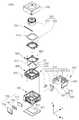
도 1은 본 발명의 일 실시예에 따른 카메라 모듈의 개략 분해 사시도이고,
도 2a는 본 발명의 일 실시예에 따른 카메라 모듈에 제공되는 제1 프레임 및 제1 볼 베어링부의 사시도이고,
도 2b는 본 발명의 일 실시예에 따른 카메라 모듈에 제공되는 제1 프레임 및 제1 볼 베어링부의 평면도이고,
도 3a는 본 발명의 일 실시예에 따른 카메라 모듈에 제공되는 제1 프레임에 제2 프레임이 수용된 모습을 도시한 사시도이고,
도 3b는 본 발명의 일 실시예에 따른 카메라 모듈에 제공되는 제1 프레임에 제2 프레임이 수용된 모습을 도시한 평면도이고,
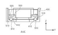
도 4a는 도 3a의 부분 절개 사시도이고,
도 4b는 도 3b의 A-A' 부분의 단면도이고,
도 5a는 본 발명의 일 실시예에 따른 카메라 모듈에 제공되는 제1 프레임, 제2 프레임 및 제2 볼 베어링부의 사시도이고,
도 5b는 본 발명의 일 실시예에 따른 카메라 모듈에 제공되는 제1 프레임, 제2 프레임 및 제2 볼 베어링부의 평면도이고,
도 6a는 본 발명의 일 실시예에 따른 카메라 모듈에 제공되는 제1 프레임에 제2 프레임과 렌즈 모듈이 수용된 모습을 도시한 사시도이고,
도 6b는 본 발명의 일 실시예에 따른 카메라 모듈에 제공되는 제1 프레임에 제2 프레임과 렌즈 모듈이 수용된 모습을 도시한 평면도이고,
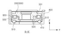
도 7a는 도 6a의 부분 절개 사시도이고,
도 7b는 도 6b의 B-B' 부분의 단면도이고,
도 8은 본 발명의 일 실시예에 따른 손떨림 보정부와 요크부의 관계를 나타낸 사시도이고,
도 9는 본 발명의 일 실시예에 따른 제1 손떨림 보정부에 제공되는 제1 마그네트 및 제1 코일의 사시도이고,
도 10a 및 10b는 본 발명의 일 실시예에 따른 제1 손떨림 보정부에 제공되는 제1 마그네트 및 제1 코일의 측면도이고,
도 11은 도 9의 C-C' 부분의 단면도이다.1 is a schematic exploded perspective view of a camera module according to an embodiment of the present invention,
2A is a perspective view of a first frame and a first ball bearing portion provided in a camera module according to an embodiment of the present invention,
2B is a plan view of a first frame and a first ball bearing portion provided in a camera module according to an embodiment of the present invention,
3A is a perspective view showing a state in which a second frame is accommodated in a first frame provided in a camera module according to an embodiment of the present invention,
3B is a plan view showing a state where a second frame is accommodated in a first frame provided in a camera module according to an embodiment of the present invention,
FIG. 4A is a partial cutaway perspective view of FIG. 3A,
FIG. 4B is a cross-sectional view taken along line AA 'of FIG. 3B,
5A is a perspective view of a first frame, a second frame, and a second ball bearing portion provided in a camera module according to an embodiment of the present invention,
5B is a plan view of a first frame, a second frame, and a second ball bearing portion provided in a camera module according to an embodiment of the present invention,
6A is a perspective view illustrating a state where a second frame and a lens module are accommodated in a first frame provided in a camera module according to an embodiment of the present invention,
6B is a plan view showing a state where a second frame and a lens module are accommodated in a first frame provided in a camera module according to an embodiment of the present invention,
FIG. 7A is a partial cutaway perspective view of FIG. 6A,
FIG. 7B is a cross-sectional view of the BB 'portion of FIG. 6B,
8 is a perspective view showing the relationship between the shake correction unit and the yoke unit according to the embodiment of the present invention,
9 is a perspective view of a first magnet and a first coil provided in the first camera-shake correction unit according to an embodiment of the present invention,
10A and 10B are side views of a first magnet and a first coil provided in a first camera-shake correction unit according to an embodiment of the present invention,
11 is a cross-sectional view of the CC 'portion of FIG.
이하에서는 도면을 참조하여 본 발명의 구체적인 실시예를 상세하게 설명한다. 다만, 본 발명의 사상은 제시되는 실시예에 제한되지 아니하고, 본 발명의 사상을 이해하는 당업자는 동일한 사상의 범위 내에서 다른 구성요소를 추가, 변경 또는 삭제 등을 통하여, 퇴보적인 다른 발명이나 본 발명 사상의 범위 내에 포함되는 다른 실시예를 용이하게 제안할 수 있을 것이나, 이 또한 본원 발명 사상의 범위 내에 포함된다고 할 것이다.
Hereinafter, specific embodiments of the present invention will be described in detail with reference to the drawings. It will be apparent to those skilled in the art that various modifications and variations can be made in the present invention without departing from the spirit or scope of the inventive concept. Other embodiments falling within the scope of the inventive concept may be easily suggested, but are also included within the scope of the present invention.
또한, 각 실시예의 도면에 나타나는 동일한 사상의 범위 내의 기능이 동일한 구성요소는 동일한 참조부호를 사용하여 설명한다.The same reference numerals are used to designate the same components in the same reference numerals in the drawings of the embodiments.
방향에 대한 용어를 정의하면, 도 1에서 볼 때 광축 방향(Z 방향)은 렌즈 모듈을 기준으로 상하 방향을 의미하고, 제1 방향(X 방향)은 상기 광축 방향(Z 방향)에 수직한 방향을 의미하며, 제2 방향(Y 방향)은 상기 광축 방향(Z 방향) 및 상기 제1 방향(X 방향)에 모두 수직한 방향을 의미한다.
1, the optical axis direction (Z direction) refers to a vertical direction with respect to the lens module, and the first direction (X direction) refers to a direction perpendicular to the optical axis direction (Z direction) , And the second direction (Y direction) means a direction perpendicular to both the optical axis direction (Z direction) and the first direction (X direction).
도 1은 본 발명의 일 실시예에 따른 카메라 모듈의 개략 분해 사시도이다.
1 is a schematic exploded perspective view of a camera module according to an embodiment of the present invention.
도 1을 참조하면, 본 발명의 일 실시예에 따른 카메라 모듈(1000)은 하우징(200), 상기 하우징(200)에 수용되는 제1 프레임(400), 상기 제1 프레임(400)에 수용되는 제2 프레임(500)과 렌즈 모듈(300), 상기 하우징(200)과 결합하는 케이스(100) 및 렌즈 구동 장치(600, 700)를 포함한다.
1, a
상기 렌즈 모듈(300)은 렌즈 배럴(310)과 상기 렌즈 배럴(310)을 내부에 수용하는 제3 프레임(330)을 포함한다.The
상기 렌즈 배럴(310)은 피사체를 촬상하는 복수의 렌즈가 내부에 수용될 수 있도록 중공의 원통 형상일 수 있으며, 상기 복수의 렌즈는 광축을 따라 상기 렌즈 배럴(310)에 구비된다.The
상기 복수의 렌즈는 상기 렌즈 배럴(310)의 설계에 따라 필요한 수만큼 적층되고, 각각의 상기 렌즈는 동일하거나 상이한 굴절률 등의 광학적 특성을 가진다.The plurality of lenses are stacked as many as necessary according to the design of the
상기 렌즈 배럴(310)은 상기 제3 프레임(330)과 결합한다. 예를 들어, 상기 제3 프레임(330)에 구비된 중공에 상기 렌즈 배럴(310)이 삽입되어 고정된다.The
상기 제3 프레임(330)은 상기 제2 프레임(500)과 함께 상기 제1 프레임(400)의 내부에 수용된다. 예를 들어, 상기 제1 프레임(400)의 내부에 상기 제2 프레임(500)과 상기 제3 프레임(330)이 순서대로 배치될 수 있다.The
따라서, 상기 제2 프레임(500)은 상기 제3 프레임(330)과 상기 제1 프레임(400) 사이에 배치된다.Accordingly, the
또한, 상기 제2 프레임(500)과 상기 제3 프레임(330)은 상기 제1 프레임(400)의 내부 바닥면으로부터 광축 방향(Z 방향)으로 이격 배치된다.The
예를 들어, 상기 제1 프레임(400)의 내부 바닥면과 상기 제2 프레임(500)의 하부면은 상기 광축 방향(Z 방향)으로 이격되어 배치되며, 상기 제2 프레임(500)의 상부면과 상기 제3 프레임(330)의 하부면도 상기 광축 방향(Z 방향)으로 이격되어 배치된다.
For example, the inner bottom surface of the
상기 하우징(200)에는 상기 제1 프레임(400), 상기 제2 프레임(500) 및 상기 제3 프레임(330)이 수용된다.The
또한, 상기 하우징(200)의 하부에는 이미지 센서(810)가 실장된 제1 기판(800)이 결합된다.A
상기 하우징(200)은 외부 광이 입사되어 상기 이미지 센서(810)에 수광되도록 상기 광축 방향(Z 방향)으로 개방된 형상으로 제공된다.The
한편, 자동 초점 조정을 위하여 상기 제1 프레임(400), 상기 제2 프레임(500) 및 상기 제3 프레임(330)은 상기 하우징(200) 내에서 상기 광축 방향(Z 방향)으로 구동될 수 있다.Meanwhile, the
이때, 상기 제1 프레임(400), 상기 제2 프레임(500) 및 상기 제3 프레임(330)의 이동 거리를 제한하도록 상기 하우징(200)의 상부에는 스토퍼(210)가 장착될 수 있다.At this time, a
상기 스토퍼(210)는 상기 제3 프레임(330)이 외부 충격 등에 의하여 상기 하우징(200)의 외부로 이탈되는 것을 방지하는 기능도 구비한다.
The
상기 케이스(100)는 상기 하우징(200)의 외부면을 감싸도록 상기 하우징(200)과 결합하며, 카메라 모듈의 구동 중에 발생되는 전자파를 차폐하는 기능을 할 수 있다.The
즉, 카메라 모듈은 구동시에 전자파가 발생되고, 이와 같은 전자파가 외부로 방출되는 경우에는 다른 전자부품에 영향을 미쳐 통신 장애나 오작동을 유발시킬 수 있게 된다.That is, the electromagnetic wave is generated at the time of driving the camera module, and when the electromagnetic wave is emitted to the outside, it affects the other electronic parts, thereby causing communication failure or malfunction.
본 실시예에서 상기 케이스(100)는 금속재질로 제공되어 상기 제1 기판(800)에 구비되는 접지패드에 접지될 수 있으며, 이에 따라 전자파를 차폐할 수 있다.In this embodiment, the
또한, 상기 케이스(100)가 플라스틱 사출물로 제공될 경우에는 상기 케이스(100)의 내부면에 전도성 도료가 도포되어 전자파를 차폐할 수 있다.In addition, when the
상기 전도성 도료로는 전도성 에폭시가 사용될 수 있으나, 이에 한정되는 것은 아니며 전도성을 가진 다양한 재료가 사용될 수 있고, 전도성 필름 또는 전도성 테이프를 상기 케이스(100)의 내부면에 부착하는 방식도 가능하다.
As the conductive paint, conductive epoxy may be used, but not limited thereto, various materials having conductivity may be used, and a conductive film or a conductive tape may be attached to the inner surface of the
상기 제1 프레임(400), 상기 제2 프레임(500) 및 상기 제3 프레임(330)은 상기 하우징(200)에 대하여 상대 이동 가능하도록 배치된다.The
또한, 상기 제3 프레임(330)과 상기 제2 프레임(500)은 상기 제1 프레임(400)의 내부에서 상기 제1 프레임(400)에 대하여 상대 이동 가능하도록 배치된다.The
이를 위하여, 본 발명의 일 실시예에 따른 카메라 모듈(1000)은 상기 렌즈 구동 장치(600, 700)를 구비한다.To this end, the
상기 렌즈 구동 장치(600, 700)는 손떨림 보정부(600)와 오토 포커싱 구동부(700)를 포함한다.The
상기 손떨림 보정부(600)는 이미지 촬영 또는 동영상 촬영 시 사용자의 손떨림과 같은 요인에 의해 이미지가 번지거나 동영상이 흔들리는 것을 보정하기 위해 사용된다.The camera
예를 들어, 상기 손떨림 보정부(600)는 영상 촬영 시 사용자의 손떨림이 발생할 때, 상기 제3 프레임(330)에 상기 손떨림에 대응하는 상대변위를 부여함으로써 손떨림을 보상한다.For example, the hand
이를 위하여, 상기 손떨림 보정부(600)는 상기 제2 프레임(500) 및 상기 제3 프레임(330)을 상기 제1 방향(X 방향)으로 구동시키는 제1 손떨림 보정부(610) 및 상기 제3 프레임(330)을 상기 제2 방향(Y 방향)으로 구동시키는 제2 손떨림 보정부(620)를 포함한다.The camera
상기 제1 손떨림 보정부(610)는 상기 제1 방향(X 방향)으로의 구동력을 발생시키기 위하여 제1 마그네트(611) 및 상기 제1 마그네트(611)와 마주보도록 배치되는 제1 코일(613)을 포함하고, 상기 제1 마그네트(611)의 위치를 센싱하도록 제1 홀 센서(615)를 더 포함할 수 있다.The first camera
또한, 상기 제2 손떨림 보정부(620)는 상기 제2 방향(Y 방향)으로의 구동력을 발생시키기 위하여 제2 마그네트(621) 및 상기 제2 마그네트(621)와 마주보도록 배치되는 제2 코일(623)을 포함하고, 상기 제2 마그네트(621)의 위치를 센싱하도록 제2 홀 센서(625)를 더 포함할 수 있다.The second camera
상기 제1 마그네트(611)와 상기 제2 마그네트(621)는 상기 제3 프레임(330)에 장착된다.The
상기 제1 코일(613) 및 상기 제2 코일(623)은 제2 기판(630)에 장착된 상태로 상기 제1 마그네트(611) 및 상기 제2 마그네트(621)와 각각 상기 광축 방향(Z 방향)에 수직한 방향으로 마주보도록 배치되며, 상기 제2 기판(630)은 상기 하우징(200)에 고정된다.The
상기 제1 마그네트(611)와 상기 제2 마그네트(621)는 상기 광축 방향(Z 방향)에 수직한 평면에서 서로 직교하도록 배치된다.The
상기 제1 손떨림 보정부(610)는 상기 제1 마그네트(611)와 상기 제1 코일(613) 사이의 전자기적 영향력에 의해 상기 제1 방향(X 방향)으로의 구동력을 발생시킨다.The first camera
또한, 상기 제2 손떨림 보정부(620)는 상기 제2 마그네트(621)와 상기 제2 코일(623) 사이의 전자기적 영향력에 의해 상기 제2 방향(Y 방향)으로의 구동력을 발생시킨다.In addition, the second hand
따라서, 상기 제3 프레임(330)은 상기 제1 손떨림 보정부(610)에 의한 구동력에 의하여 상기 제1 방향(X 방향)으로 구동하게 되고, 상기 제2 손떨림 보정부(620)에 의한 구동력에 의하여 상기 제2 방향(Y 방향)으로 구동하게 된다.Accordingly, the
한편, 상기 제1 손떨림 보정부(610)에 의하여 상기 제3 프레임(330)은 상기 제2 프레임(500)과 함께 상기 제1 프레임(400)에 대하여 상대 이동되며, 상기 제2 손떨림 보정부(620)에 의하여 상기 제3 프레임(330)은 상기 제2 프레임(500)에 대하여 상대 이동된다.Meanwhile, the
이때, 상기 제2 프레임(500)과 상기 제3 프레임(330)이 상기 제1 프레임(400)에 대하여 상대 이동되는 것을 지지하도록 제1 볼 베어링부(910)가 제공되고, 상기 제3 프레임(330)이 상기 제2 프레임(500)에 대하여 상대 이동되는 것을 지지하도록 제2 볼 베어링부(920)가 제공된다.At this time, a first
이에 대하여는 도 2a 내지 도 7b를 참조로 자세히 설명하도록 한다.
This will be described in detail with reference to FIGS. 2A to 7B.
상기 오토 포커싱 구동부(700)는 자동 초점 조정 또는 줌 기능을 위하여 사용된다.The
상기 오토 포커싱 구동부(700)에 의하여 상기 제3 프레임(330)을 상기 광축 방향(Z 방향)으로 구동시킴으로써 자동 초점 조정 또는 줌 기능을 수행할 수 있게 된다.The auto focus adjustment or zoom function can be performed by driving the
예를 들어, 상기 오토 포커싱 구동부(700)는 상기 제1 프레임(400)의 일면에 구비되는 제3 마그네트(710), 상기 제3 마그네트(710)와 마주보도록 배치되는 제3 코일(730), 상기 제3 코일(730)에 전원을 인가하는 제3 기판(770)을 포함하고, 상기 제3 마그네트(710)의 위치를 센싱하도록 제3 홀 센서(750)를 더 포함할 수 있다.For example, the auto focusing
상기 제3 코일(730)은 제3 기판(770)에 장착되어 상기 제3 마그네트(710)와 대향 배치되며, 상기 제3 기판(770)은 상기 하우징(200)의 일면에 고정된다.The
상기 오토 포커싱 구동부(700)는 상기 제3 마그네트(710)와 상기 제3 코일(730) 사이의 전자기적 영향력에 의하여 상기 제1 프레임(400)을 상기 광축 방향(Z 방향)으로 이동시킬 수 있다.The
예를 들어, 상기 제3 마그네트(710)는 자기장을 형성하며 상기 제3 코일(730)에 전원이 인가되면, 상기 제3 마그네트(710)와 상기 제3 코일(730) 사이의 전자기적 영향력에 의한 구동력이 발생하고 상기 구동력에 의해 상기 제1 프레임(400)을 상기 광축 방향(Z 방향)으로 이동시킬 수 있다.For example, when the
여기서, 상기 제3 프레임(330) 및 상기 제2 프레임(500)은 상기 제1 프레임(400)의 내부에 수용되므로, 상기 제1 프레임(400)이 상기 광축 방향(Z 방향)으로 이동함에 따라 상기 제3 프레임(330) 및 상기 제2 프레임(500)도 상기 광축 방향(Z 방향)으로 이동하게 된다.Since the
즉, 상기 제1 프레임(400), 상기 제2 프레임(500) 및 상기 제3 프레임(330)은 상기 오토 포커싱 구동부(700)에 의하여 상기 광축 방향(Z 방향)으로 구동될 수 있다.That is, the
이때, 상기 제1 프레임(400), 상기 제2 프레임(500) 및 상기 제3 프레임(330)은 상기 하우징(200)에 대하여 상대 이동된다.At this time, the
상기 제1 프레임(400), 상기 제2 프레임(500) 및 상기 제3 프레임(330)이 상기 하우징(200)에 대하여 상대 이동되는 것을 지지하도록 상기 제1 프레임(400)의 일면에는 상기 광축 방향(Z 방향)을 따라 제3 볼 베어링부(930)가 구비될 수 있다.The
상기 제3 볼 베어링부(930)는 상기 제3 마그네트(710)의 양측에 배치되고, 상기 하우징(200)의 내부면 및 상기 제1 프레임(400)의 일면과 접촉하며, 상기 광축 방향(Z 방향)으로 구름운동한다.The
상기 하우징(200)의 상부면 중에서 상기 제3 마그네트(710)에 인접한 위치에는 이탈 방지 부재(230)가 구비될 수 있다.A
상기 이탈 방지 부재(230)는 상기 제3 볼 베어링부(930)가 상기 하우징(200)과 상기 제1 프레임(400) 사이에서 이탈되는 것을 방지하는 기능을 한다.
The
도 2a는 본 발명의 일 실시예에 따른 카메라 모듈에 제공되는 제1 프레임 및 제1 볼 베어링부의 사시도이고, 도 2b는 본 발명의 일 실시예에 따른 카메라 모듈에 제공되는 제1 프레임 및 제1 볼 베어링부의 평면도이다.FIG. 2A is a perspective view of a first frame and a first ball bearing portion provided in a camera module according to an embodiment of the present invention, FIG. 2B is a perspective view of a first frame and a first ball bearing portion provided in a camera module according to an embodiment of the present invention, And a plan view of the ball bearing portion.
또한, 도 3a는 본 발명의 일 실시예에 따른 카메라 모듈에 제공되는 제1 프레임에 제2 프레임이 수용된 모습을 도시한 사시도이고, 도 3b는 본 발명의 일 실시예에 따른 카메라 모듈에 제공되는 제1 프레임에 제2 프레임이 수용된 모습을 도시한 평면도이다.FIG. 3A is a perspective view showing a state where a second frame is accommodated in a first frame provided in a camera module according to an embodiment of the present invention, FIG. 3B is a perspective view of a camera module according to an embodiment of the present invention, And the second frame is accommodated in the first frame.
또한, 도 4a는 도 3a의 부분 절개 사시도이고, 도 4b는 도 3b의 A-A' 부분의 단면도이다.
FIG. 4A is a partial cutaway perspective view of FIG. 3A, and FIG. 4B is a cross sectional view of a portion AA 'of FIG. 3B.
먼저, 도 2a 내지 도 4를 참조하여, 상기 제1 손떨림 보정부(610)에 관하여 설명한다.
First, referring to Figs. 2A to 4, the first
상기 제2 프레임(500)은 상기 제1 프레임(400)에 수용되고, 상기 제1 손떨림 보정부(610)에 의하여 상기 제1 방향(X 방향)으로 구동된다.The
여기서, 상기 제1 프레임(400)과 상기 제2 프레임(500) 사이에는 상기 제1 볼 베어링부(910)가 구비된다.Here, the first
본 실시예에서는 상기 제1 볼 베어링부(910)에 4개의 볼 베어링이 구비되나, 상기 볼 베어링의 개수에 본 발명의 사상이 제한되는 것은 아니다.Although four ball bearings are provided in the first
상기 제1 볼 베어링부(910)는 상기 제2 프레임(500)이 상기 제1 프레임(400)과의 간격을 유지하면서 상기 제1 방향(X 방향)으로 구동되도록 상기 제2 프레임(500)을 지지한다.The first
상기 제1 프레임(400)과 상기 제2 프레임(500)에는 각각 상기 제1 볼 베어링부(910)를 수용하도록 제1 수용홈(410, 510)이 형성된다.The
상기 제1 수용홈(410, 510)은 상기 제1 프레임(400)의 내부 바닥면과 상기 제2 프레임(500)의 하부면에 각각 형성되며, 상기 제1 볼 베어링부(910)는 상기 제1 프레임(400)과 상기 제2 프레임(500)이 상기 광축 방향(Z 방향)으로 이격 배치되도록 상기 제1 수용홈(410, 510)에 끼워진다.The first receiving
상기 제1 수용홈(410, 510)은 상기 제1 볼 베어링부(910)가 상기 제1 방향(X 방향)으로 구름운동하는 것을 안내하고, 상기 제1 방향(X 방향)에 수직한 방향으로의 이동을 제한할 수 있다.The first receiving
예를 들어, 상기 제1 수용홈(410, 510)의 폭(Y 방향)은 상기 제1 볼 베어링부(910)의 크기에 대응되도록 형성되며, 상기 제1 수용홈(910)의 길이(X 방향)는 상기 제1 볼 베어링부(910)가 구름운동할 수 있도록 상기 제1 방향(X 방향)으로 길게 형성된다.For example, the width (Y direction) of the first receiving
따라서, 상기 제1 볼 베어링부(910)는 상기 제1 방향(X 방향)으로 구름운동할 수 있고, 상기 광축 방향(Z 방향) 및 상기 제2 방향(Y 방향)으로의 이동이 제한될 수 있다.Accordingly, the first
따라서, 상기 제1 손떨림 방지부(610)에 의하여 상기 제2 프레임(500)은 상기 제1 볼 베어링부(910)에 지지된 상태로 상기 제1 방향(X 방향)으로 구동될 수 있다.Accordingly, the
도 2a 내지 도 4b에는 설명의 편의를 위하여 상기 제1 프레임(400)에 상기 제2 프레임(500)만이 수용된 모습이 도시되었으나, 이하에서 설명하는 바와 같이, 상기 제1 프레임(400)에는 상기 제3 프레임(330)도 수용되며, 상기 제2 프레임(500)의 구동에 따라 상기 제3 프레임(330)도 상기 제1 방향(X 방향)으로 구동될 수 있다.2A to 4B illustrate a state in which only the
즉, 상기 제1 손떨림 보정부(610)에 의하여 상기 제3 프레임(330) 및 상기 제2 프레임(500)이 상기 제1 프레임(400)에 대하여 상대 이동되며, 이에 따라, 상기 제1 방향(X 방향)으로의 손떨림 보정이 가능하게 된다.That is, the
상기 제1 볼 베어링부(910)는 상기 광축 방향(Z 방향) 및 상기 제2 방향(Y 방향)으로의 이동이 제한되므로, 상기 제1 손떨림 보정부(610)의 구동력에 의하여 상기 제2 프레임(500) 및 상기 제3 프레임(330)은 상기 제1 방향(X 방향)으로만 구동되게 된다.
The movement of the first
도 5a는 본 발명의 일 실시예에 따른 카메라 모듈에 제공되는 제1 프레임, 제2 프레임 및 제2 볼 베어링부의 사시도이고, 도 5b는 본 발명의 일 실시예에 따른 카메라 모듈에 제공되는 제1 프레임, 제2 프레임 및 제2 볼 베어링부의 평면도이다.FIG. 5A is a perspective view of a first frame, a second frame and a second ball bearing portion provided in a camera module according to an embodiment of the present invention. Frame, a second frame, and a second ball bearing portion.
또한, 도 6a는 본 발명의 일 실시예에 따른 카메라 모듈에 제공되는 제1 프레임에 제2 프레임과 제3 프레임이 수용된 모습을 도시한 사시도이고, 도 6b는 본 발명의 일 실시예에 따른 카메라 모듈에 제공되는 제1 프레임에 제2 프레임과 제3 프레임이 수용된 모습을 도시한 평면도이다.6A is a perspective view illustrating a state in which a second frame and a third frame are accommodated in a first frame provided in a camera module according to an embodiment of the present invention. And a second frame and a third frame are accommodated in a first frame provided to the module.
또한, 도 7a는 도 6a의 부분 절개 사시도이고, 도 7b는 도 6b의 B-B' 부분의 단면도이다.
FIG. 7A is a partially cutaway perspective view of FIG. 6A, and FIG. 7B is a cross-sectional view of a portion BB 'of FIG. 6B.
도 6a 내지 도 7b를 참조하여, 상기 제2 손떨림 보정부(620)에 관하여 설명한다.The second hand
상기 제1 프레임(400)에는 상기 제2 프레임(500)과 상기 제3 프레임(330)이 수용된다.The
상기 제2 프레임(500)과 상기 제3 프레임(330)은 순서대로 상기 제1 프레임(400)에 삽입 배치되고, 상기 제1 프레임(400), 상기 제2 프레임(500) 및 상기 제3 프레임(330)은 각각 상기 광축 방향(Z 방향)으로 이격 배치된다.The
앞서 설명한 바와 같이, 상기 제1 손떨림 보정부(610)에 의하여 상기 제2 프레임(500)과 상기 제3 프레임(330)은 상기 제1 방향(X 방향)으로 구동된다.As described above, the
여기서, 상기 제3 프레임(330)은 상기 제2 손떨림 보정부(620)에 의하여 상기 제2 방향(Y 방향)으로도 구동된다.Here, the
상기 제2 프레임(500)과 상기 제3 프레임(330) 사이에는 제2 볼 베어링부(920)가 구비된다.A second
본 실시예에서는 상기 제2 볼 베어링부(920)에 4개의 볼 베어링이 구비되나, 상기 볼 베어링의 개수에 본 발명의 사상이 제한되는 것은 아니다.Although four ball bearings are provided in the second
상기 제2 볼 베어링부(920)는 상기 제3 프레임(330)이 상기 제2 프레임(500)과의 간격을 유지하면서 상기 제2 방향(Y 방향)으로 구동되도록 상기 제3 프레임(330)을 지지한다.The second
상기 제2 프레임(500)과 상기 제3 프레임(330)에는 각각 상기 제2 볼 베어링부(920)를 수용하도록 제2 수용홈(520, 331)이 형성된다.The
상기 제2 수용홈(520, 331)은 상기 제2 프레임(500)의 상부면과 상기 제3 프레임(330)의 하부면에 각각 형성되며, 상기 제2 볼 베어링부(920)는 상기 제2 프레임(500)과 상기 제3 프레임(330)이 상기 광축 방향(Z 방향)으로 이격 배치되도록 상기 제2 수용홈(520, 331)에 끼워진다.The second receiving recesses 520 and 331 are formed on the upper surface of the
상기 제2 수용홈(520, 331)은 상기 제2 볼 베어링부(920)가 상기 제2 방향(Y 방향)으로 구름운동하는 것을 안내하고, 상기 제2 방향(Y 방향)에 수직한 방향으로의 이동을 제한할 수 있다.The second receiving recesses 520 and 331 guide the second
예를 들어, 상기 제2 수용홈(520, 331)의 폭(X 방향)은 상기 제2 볼 베어링부(920)의 크기에 대응되도록 형성되며, 상기 제2 수용홈(520, 331)의 길이(Y 방향)는 상기 제2 볼 베어링부(920)가 구름운동할 수 있도록 상기 제2 방향(Y 방향)으로 길게 형성된다.For example, the width (X direction) of the second receiving recesses 520 and 331 is formed to correspond to the size of the second
따라서, 상기 제2 볼 베어링부(920)는 상기 제2 방향(Y 방향)으로 구름운동할 수 있고, 상기 광축 방향(Z 방향) 및 상기 제1 방향(X 방향)으로의 이동이 제한될 수 있다.Accordingly, the second
상기 제2 손떨림 보정부(620)에 의하여 상기 제3 프레임(330)은 상기 제2 볼 베어링부(920)에 지지된 상태로 상기 제2 방향(Y 방향)으로 구동될 수 있다.The
즉, 상기 제2 손떨림 보정부(620)에 의하여 상기 제3 프레임(330)이 상기 제2 프레임(500)에 대하여 상대 이동되며, 이에 따라, 상기 제2 방향(Y 방향)으로의 손떨림 보정이 가능하게 된다.That is, the
상기 제2 볼 베어링부(920)는 상기 광축 방향(Z 방향) 및 상기 제1 방향(X 방향)으로의 이동이 제한되므로, 상기 제2 손떨림 보정부(620)의 구동력에 의하여 상기 제3 프레임(330)은 상기 제2 방향(Y 방향)으로만 구동되게 된다.The movement of the second
즉, 상기 제3 프레임(330)은 상기 제1 손떨림 보정부(610)의 구동력과 상기 제2 손떨림 보정부(620)의 구동력에 의하여 각각 상기 제1 방향(X 방향) 및 상기 제2 방향(Y 방향)으로 독립적으로 구동되게 된다.That is, the
예를 들어, 상기 제1 손떨림 보정부(610)의 구동력에 의하여 상기 제3 프레임(330)은 상기 제1 방향(X 방향)으로만 구동되고 상기 제2 방향(Y 방향) 및 상기 광축 방향(Z 방향)으로는 구동되지 않으며, 상기 제2 손떨림 보정부(620)의 구동력에 의하여 상기 제3 프레임(330)은 상기 제2 방향(Y 방향)으로만 구동되고 상기 제1 방향(X 방향) 및 상기 광축 방향(Z 방향)으로는 구동되지 않는다.For example, the
상기에서 설명한 바와 같이, 상기 제1 볼 베어링부(910)와 상기 제2 볼 베어링(920)가 상기 제3 프레임(330)을 지지하므로, 손떨림 보정 시에 구동 변위의 발생을 방지할 수 있다.
As described above, since the first
한편, 상기 제1 손떨림 보정부(610)의 구동력은 상기 제2 손떨림 보정부(620)의 구동력보다 크다.On the other hand, the driving force of the first camera
상기 제1 손떨림 보정부(610)는 상기 제2 프레임(500)과 상기 제3 프레임(330)을 구동시켜야 하므로, 상기 제3 프레임(330)만을 구동시키는 상기 제2 손떨림 보정부(620)보다 큰 구동력을 발생시키게 된다.The first camera
따라서, 상기 제1 손떨림 보정부(610)에 제공되는 상기 제1 마그네트(611)는 서로 대칭되게 배치되는 두 개의 마그네트를 포함한다.Accordingly, the
또한, 상기 제1 코일(613)은 상기 두 개의 마그네트에 각각 대향 배치되도록 두 개의 코일을 포함한다.In addition, the
또한, 상기 오토 포커싱 구동부(700)의 구동력은 상기 제1 손떨림 보정부(610) 및 상기 제2 손떨림 보정부(620)의 구동력보다 크다.The driving force of the auto focusing
상기 오토 포커싱 구동부(700)는 상기 제1 프레임(400) 및 상기 제2 프레임(500)과 상기 제3 프레임(330)을 모두 구동시켜야 하므로, 상기 제2 프레임(400) 및 상기 제3 프레임(330)을 구동시키는 상기 제1 손떨림 보정부(610)보다 큰 구동력을 발생시키며, 상기 제3 프레임(330)만을 구동시키는 상기 제2 손떨림 보정부(620)보다 큰 구동력을 발생시키게 된다.
The
도 8은 본 발명의 일 실시예에 따른 손떨림 보정부와 요크부의 관계를 나타낸 사시도이다.
8 is a perspective view showing the relationship between the shake correction unit and the yoke unit according to the embodiment of the present invention.
도 8을 참조하여, 본 발명의 일 실시예에 따른 상기 손떨림 보정부(600)의 구동에 대하여 설명한다.
Referring to FIG. 8, the operation of the camera
본 발명의 일 실시예에 따른 카메라 모듈(1000)에는 상기 손떨림 보정부(600)와 상기 광축 방향(Z 방향)으로 마주보도록 복수의 요크부(231, 233)가 제공되며, 상기 복수의 요크부(231, 233)는 상기 제1 프레임(400)에 장착된다.The
예를 들어, 제1 요크부(231)는 상기 제1 손떨림 보정부(610)와 상기 광축 방향(Z 방향)으로 마주보도록 상기 제1 프레임(400)에 장착되고, 제2 요크부(233)는 상기 제2 손떨림 보정부(620)와 상기 광축 방향(Z 방향)으로 마주보도록 상기 제1 프레임(400)에 장착된다.For example, the
여기서, 상기 손떨림 보정부(600)와 상기 제1 프레임(400) 사이에는 상기 광축 방향(Z 방향)으로 자기력이 작용한다.Here, a magnetic force acts between the hand
예를 들어, 상기 제1 프레임(400)에 장착되는 상기 제1 요크부(231) 및 상기 제2 요크부(233)는 자성체로 제공되므로, 상기 제1 요크부(231)와 상기 제1 손떨림 보정부(610) 사이에는 자기력이 작용하며, 상기 제2 요크부(233)와 상기 제2 손떨림 보정부(620) 사이에도 자기력이 작용한다. 상기 자기력은 전기적인 인력을 의미할 수 있다.For example, since the
상기 제1 요크부(231) 및 상기 제2 요크부(233)는 고정 부재이므로, 상기 자기력에 의하여 상기 제1 손떨림 보정부(610)와 상기 제2 손떨림 보정부(620)는 각각 상기 제1 요크부(231) 및 상기 제2 요크부(233)를 향하는 방향으로 당겨지게 된다.The
이에 따라, 상기 제1 손떨림 보정부(610) 및 상기 제2 손떨림 보정부(620)가 장착된 상기 제3 프레임(330)이 상기 제1 요크부(231) 및 상기 제2 요크부(233)가 장착된 상기 제1 프레임(400)을 향하는 방향으로 당겨지게 된다.The
따라서, 상기 제1 프레임(400)과 상기 제2 프레임(500)은 상기 제1 볼 베어링부(910)와 접촉 상태를 유지할 수 있고, 상기 제2 프레임(500)과 상기 제3 프레임(330)은 상기 제2 볼 베어링부(920)와 접촉 상태를 유지할 수 있다.Accordingly, the
따라서, 외부 충격 등이 발생하더라도 상기 제3 프레임(330), 상기 제1 프레임(400) 및 상기 제2 프레임(500)은 각각 서로 간의 간격을 유지할 수 있으므로, 본 발명의 일 실시예에 따른 카메라 모듈(1000)은 외부 충격 등에 대한 신뢰성을 확보할 수 있다.
Therefore, even if an external impact or the like occurs, the
한편, 상기 제1 손떨림 보정부(610)와 상기 제2 손떨림 보정부(620)에 구동 신호가 인가되지 않은 상태에서는 상기 전기적인 인력에 의하여 상기 제2 프레임(500) 및 상기 제3 프레임(330)은 상기 제1 방향(X 방향) 및 상기 제2 방향(Y 방향)으로 움직이지 않고 고정되어 있다.Meanwhile, when no driving signal is applied to the first and second
상기 제1 손떨림 보정부(610)에 구동 신호가 인가되면, 상기 제1 마그네트(611)와 상기 제1 코일(613) 사이의 전기적인 영향력에 의해 상기 제1 방향(X 방향)으로 구동력이 발생하게 된다.A driving force is generated in the first direction (X direction) by an electrical influence between the
이때, 상기 제1 손떨림 보정부(610)의 구동력의 크기는 상기 제1 마그네트(611)와 상기 제1 요크부(231) 사이의 전기적인 인력의 크기보다 크므로, 상기 제1 손떨림 보정부(610)의 구동력에 의하여 상기 제2 프레임(500) 및 상기 제3 프레임(330)이 상기 제1 방향(X 방향)으로 구동되게 된다.Since the magnitude of the driving force of the first camera
그러나, 상기 제1 손떨림 보정부(610)에 인가된 상기 구동 신호가 제거되면, 상기 제1 마그네트(611)와 상기 제1 요크부(231) 사이의 전기적인 인력에 의하여 상기 제2 프레임(500) 및 상기 제3 프레임(330)은 초기 위치로 돌아가게 된다.However, when the drive signal applied to the first camera-
여기서, 초기 위치란 상기 제1 손떨림 보정부(610)에 상기 구동 신호가 인가되기 전에 상기 제2 프레임(500) 및 상기 제3 프레임(330)이 있던 위치를 의미한다.Herein, the initial position means the position where the
또한, 상기 제2 손떨림 보정부(620)에 구동 신호가 인가되면, 상기 제2 마그네트(621)와 상기 제2 코일(623) 사이의 전기적인 영향력에 의해 상기 제2 방향(Y 방향)으로 구동력이 발생하게 된다.In addition, when a drive signal is applied to the second hand
이때, 상기 제2 손떨림 보정부(620)의 구동력의 크기는 상기 제2 마그네트(621)와 상기 제2 요크부(233) 사이의 전기적인 인력의 크기보다 크므로, 상기 제2 손떨림 보정부(620)의 구동력에 의하여 상기 제3 프레임(330)이 상기 제2 방향(Y 방향)으로 구동되게 된다.Since the magnitude of the driving force of the second hand
그러나, 상기 제2 손떨림 보정부(620)에 인가된 상기 구동 신호가 제거되면, 상기 제2 마그네트(621)와 상기 제2 요크부(233) 사이의 전기적인 인력에 의하여 상기 제3 프레임(330)은 초기 위치로 돌아가게 된다.However, when the drive signal applied to the second camera-
여기서, 초기 위치란 상기 제2 손떨림 보정부(620)에 상기 구동 신호가 인가되기 전에 상기 제3 프레임(330)이 있던 위치를 의미한다.
Here, the initial position means the position where the
이하에서는, 상기 오토 포커싱 구동부(700)와 상기 손떨림 보정부(600)의 배치 관계에 대하여 설명한다.
Hereinafter, the arrangement relationship of the
상기 오토 포커싱 구동부(700)는 상기 제3 프레임(330)을 기준으로 상기 광축 방향(Z 방향)에 수직한 평면의 일측에 배치되고, 상기 손떨림 보정부(600)는 상기 오토 포커싱 구동부(700)가 배치된 일측 외의 상기 광축 방향(Z 방향)에 수직한 평면의 다른 측에 배치된다.The
예를 들어, 상기 손떨림 보정부(600)는 상기 광축 방향(Z 방향)에 수직한 평면에서 3개 측에 배치된다.For example, the hand
상기와 같은 구조에 의하여 상기 제1 손떨림 보정부(610)에 제공되는 두 개의 마그네트(상기 제1 마그네트(611))는 각각 서로 평행하게 배치되며, 상기 제2 손떨림 보정부(620)에 제공되는 상기 제2 마그네트(621)는 상기 오토 포커싱 구동부(700)에 제공되는 상기 제3 마그네트(710)와 서로 평행하게 배치된다.The two magnets (the first magnet 611) provided in the first camera-
예를 들어, 상기 제1 마그네트(611)의 두 개의 마그네트는 상기 제3 프레임(330)을 사이에 두고 서로 마주본다.For example, the two magnets of the
또한, 상기 제2 마그네트(621)와 상기 제3 마그네트(710)도 상기 제3 프레임(330)을 사이에 두고 서로 마주본다.The
따라서, 상기 제1 마그네트(611)의 두 개의 마그네트가 서로 마주보는 방향(X 방향)과 상기 제2 마그네트(621)와 상기 제3 마그네트(710)가 서로 마주보는 방향(Y 방향)은 서로 수직하게 되며, 상기 제3 프레임(330)은 상기 제1 마그네트(611), 상기 제2 마그네트(621) 및 상기 제3 마그네트(710)에 의하여 둘러싸이게 된다.
Therefore, the direction in which the two magnets of the
상기 오토 포커싱 구동부(700)를 구성하는 상기 제3 마그네트(710)는 상기 제1 프레임(400)에 구비되고, 상기 손떨림 보정부(600)를 구성하는 상기 제1 마그네트(611) 및 상기 제2 마그네트(621)는 상기 제3 프레임(330)에 구비된다.The
상기 제3 프레임(330)이 상기 제1 프레임(400)의 내부에 수용되므로, 상기 제1 마그네트(711) 및 상기 제2 마그네트(721)는 상기 광축 방향(Z 방향)에 수직한 평면에서 상기 제3 마그네트(710)보다 광축에 더 가깝게 배치된다.Since the
한편, 상기 제1 프레임(400)은 상기 제1 마그네트(611) 및 상기 제2 마그네트(621)에 대응되는 부분이 개방된 형상으로 제공된다.Meanwhile, the
상기 제1 프레임(400)의 개방된 부분에 상기 제1 코일(613) 및 상기 제2 코일(623)이 배치되며, 이로 인하여 상기 제3 프레임(330)에 구비되는 상기 제1 마그네트(611) 및 상기 제2 마그네트(621)가 각각 상기 제1 코일(613) 및 상기 제2 코일(623)과 대향 배치된다.The
상기 제3 코일(730)은 상기 제1 프레임(400)의 일면에 배치된 상기 제3 마그네트(710)와 대향 배치되므로, 상기 제3 코일(730)은 상기 제1 프레임(400)의 외측에 위치하게 된다.The
따라서, 상기 제1 코일(613) 및 상기 제2 코일(623)은 상기 광축 방향(Z 방향)에 수직한 평면에서 상기 제3 코일(730)보다 광축에 더 가깝게 배치된다.Accordingly, the
즉, 본 발명의 일 실시예에 따른 카메라 모듈(1000)에서는 상기 손떨림 보정부(600)가 상기 광축에 수직한 평면에서 상기 오토 포커싱 구동부(700)보다 광축에 더 인접하게 배치된다.That is, in the
또한, 상기 오토 포커싱 구동부(700)에 의하여 상기 제1 프레임(400)은 상기 제3 마그네트(710)가 장착된 상태로 상기 광축 방향(Z 방향)으로 구동하고, 상기 제1 프레임(400)의 구동에 따라 상기 제1 프레임(400)의 내부에 수용된 상기 제3 프레임(330)도 상기 제1 마그네트(611) 및 상기 제2 마그네트(621)가 장착된 상태로 상기 광축 방향(Z 방향)으로 구동한다.The
즉, 본 발명의 일 실시예에 따른 카메라 모듈(1000)에서는 상기 오토 포커싱 구동부(700)에 의하여 상기 제1 마그네트(611), 상기 제2 마그네트(621) 및 상기 제3 마그네트(710)가 모두 상기 광축 방향(Z 방향)으로 구동하게 된다.That is, in the
한편, 상기 손떨림 보정부(600)에 의하여 상기 제3 프레임(330)이 상기 제1 프레임(400)에 대하여 상대 이동하므로, 상기 제1 마그네트(611) 및 상기 제2 마그네트(621)는 상기 광축 방향(Z 방향) 뿐만 아니라 상기 제1 방향(X 방향)과 상기 제2 방향(Y 방향)으로도 구동한다.Since the
본 발명의 일 실시예에 따른 카메라 모듈(1000)에서는 상기 손떨림 보정부(600)의 구동력에 의하여 상기 오토 포커싱 구동부(700)는 영향을 받지 않는다.In the
상기 손떨림 보정부(600)의 구동력에 의하여 상기 제2 프레임(500)과 상기 제3 프레임(330)이 영향을 받아 구동되고 상기 제1 프레임(400)은 구동되지 않으므로, 손떨림 보정 시에 상기 제1 프레임(400)에 장착된 상기 제3 마그네트(710)는 움직이지 않게 된다.The
따라서, 손떨림 보정 시에 구동되어야 할 부재를 줄임으로써 소비 전력을 줄일 수 있다.Therefore, the power consumption can be reduced by reducing the number of members to be driven at the time of camera-shake correction.
예를 들어, 상기 제1 방향(X 방향)으로의 손떨림 보정이 필요할 경우에는 상기 제2 프레임(500)과 상기 제3 프레임(330)만을 움직이고, 상기 제2 방향(Y 방향)으로의 손떨림 보정이 필요할 경우에는 상기 제3 프레임(330)만을 움직이며, 상기 오토 포커싱 구동부(700)가 장착된 상기 제1 프레임(400)은 움직이지 않으므로, 손떨림 보정에 필요한 소비 전력을 줄일 수 있는 것이다.
For example, when the camera shake correction in the first direction (X direction) is required, only the
도 9는 본 발명의 일 실시예에 따른 제1 손떨림 보정부에 제공되는 제1 마그네트 및 제1 코일의 사시도이고, 도 10a 및 10b는 본 발명의 일 실시예에 따른 제1 손떨림 보정부에 제공되는 제1 마그네트 및 제1 코일의 측면도이며, 도 11은 도 9의 C-C' 부분의 단면도이다.
FIG. 9 is a perspective view of a first magnet and a first coil provided in the first shake correction unit according to an embodiment of the present invention, FIGS. 10A and 10B are provided to a first shake correction unit according to an embodiment of the present invention Fig. 11 is a cross-sectional view of the CC 'portion of Fig. 9. Fig. 11 is a side view of the first magnet and the first coil.
상기 제1 손떨림 보정부(610)에 제공되는 상기 제1 마그네트(611)와 상기 제1 코일(613)은 상기 제1 방향(X 방향)으로의 구동력을 발생시키도록 상기 제1 방향(X 방향)으로 마주보게 배치된다.The
여기서, 상기 제1 마그네트(611)의 크기는 상기 제1 코일(613)의 크기보다 작을 수 있다.Here, the size of the
또한, 상기 제1 코일(613)은 중공이 형성된 도넛 형상일 수 있다.In addition, the
따라서, 도 10a에 도시된 바와 같이, 상기 제1 방향(X 방향, 상기 제1 코일(613)에서 상기 광축을 향하는 방향)에서 바라볼 때, 상기 제1 마그네트(611)의 외측단은 상기 제1 코일(613)에 가려져 보이지 않게 되며, 상기 제1 마그네트(611)의 중앙은 상기 제1 코일(613)의 중공을 통해 보여지게 된다.10A, the outer end of the
또한, 도 10b에 도시된 바와 같이, 상기 제1 방향(X 방향, 상기 광축에서 상기 제1 코일(613)을 향하는 방향)에서 바라볼 때, 상기 제1 코일(613)의 중공은 상기 제1 마그네트(611)에 가려져 보이지 않게 되며, 상기 제1 코일(613)의 외측단은 상기 제1 마그네트(611)의 외측으로 돌출되게 된다.10B, the hollow of the
따라서, 상기 제1 방향(X 방향)에서 바라볼 때, 상기 제1 마그네트(611)의 상기 광축 방향(Z 방향)으로의 양 끝단과 상기 제1 코일(613)의 일부가 중첩될 수 있다.Therefore, when viewed in the first direction (X direction), both ends of the
이와 같은 배치관계를 통해, 도 11에 도시된 바와 같이, 상기 제1 마그네트(611)와 상기 제1 코일(613) 사이의 전자기적 영향력에 의하여 상기 제1 방향(X 방향)으로 구동력이 발생하게 된다.
11, a driving force is generated in the first direction (X direction) due to the electromagnetic influence between the
도 9 내지 도 11에서는 설명의 편의를 위하여 상기 제1 손떨림 보정부(610)에 관하여만 설명하였으나, 상기 제2 손떨림 보정부(620)에 제공되는 상기 제2 마그네트(621)와 상기 제2 코일(623)의 배치관계도 도 9 내지 도 11을 참조로 설명한 상기 제1 마그네트(611)와 상기 제1 코일(613)의 배치관계와 동일하며, 따라서 상기 제2 손떨림 보정부(620)는 상기 제2 방향(Y 방향)으로 구동력을 발생시킬 수 있다.
9-11 illustrate only the first camera-
이상의 실시예를 통해, 본 발명의 일 실시예에 따른 카메라 모듈은 외부 충격에 대한 신뢰성을 확보하면서도 손떨림 보정 시에 구동 변위의 발생을 방지할 수 있다.According to the embodiments described above, the camera module according to the embodiment of the present invention can prevent the occurrence of driving displacement at the time of camera-shake correction while ensuring reliability against an external impact.
또한, 소비 전력을 줄일 수 있다.
In addition, power consumption can be reduced.
상기에서는 본 발명에 따른 실시예를 기준으로 본 발명의 구성과 특징을 설명하였으나 본 발명은 이에 한정되지 않으며, 본 발명의 사상과 범위내에서 다양하게 변경 또는 변형할 수 있음은 본 발명이 속하는 기술분야의 당업자에게 명백한 것이며, 따라서 이와 같은 변경 또는 변형은 첨부된 특허청구범위에 속함을 밝혀둔다.
While the present invention has been described with reference to exemplary embodiments, it is to be understood that the invention is not limited to the disclosed exemplary embodiments, but, on the contrary, It will be apparent to those skilled in the art that changes or modifications may fall within the scope of the appended claims.
100: 케이스200: 하우징
300: 렌즈 모듈310: 렌즈 배럴
330: 제3 프레임400: 제1 프레임
500: 제2 프레임600: 손떨림 보정부
610: 제1 손떨림 보정부620: 제2 손떨림 보정부
700: 오토 포커싱 구동부910: 제1 볼 베어링부
920: 제2 볼 베어링부930: 제3 볼 베어링부100: Case 200: Housing
300: lens module 310: lens barrel
330: third frame 400: first frame
500: second frame 600: camera-shake correction unit
610: first camera-shake correction unit 620: second camera-
700: auto focusing driving part 910: first ball bearing part
920: second ball bearing portion 930: third ball bearing portion
Claims (46)
Translated fromKorean상기 제1 프레임에 수용되고, 상기 제1 프레임과 함께 상기 광축 방향으로 이동할 수 있도록 구성되는 제2 프레임과 제3 프레임; 및
광축에 수직한 제1 방향 및 제2 방향으로 구동력을 발생시키도록 구성되는 제1 및 제2 마그네트와 제1 및 제2 코일을 포함하는 손떨림 보정부;를 포함하며,
상기 제1 및 제2 마그네트는 상기 제3 프레임에 장착되고,
상기 하우징의 측벽에는 상기 하우징의 측벽을 관통하는 개구부가 형성되고,
상기 제1 코일은 상기 제1 마그네트와 상기 제1 방향으로 마주보도록 상기 개구부에 배치되고, 상기 제2 코일은 상기 제2 마그네트와 상기 제2 방향으로 마주보도록 상기 개구부에 배치되며,
상기 제2 프레임과 상기 제3 프레임은 상기 제1 프레임 내에서 상기 제1 방향으로 이동할 수 있도록 구성되고, 상기 제3 프레임은 상기 제2 프레임에 대해 상기 제2 방향으로 이동할 수 있도록 구성되며,
상기 제3 프레임에는 렌즈 배럴이 고정되고,
상기 제1 마그네트의 상기 광축 방향으로의 길이는,
상기 제1 코일에 형성된 홀의 상기 광축 방향으로의 길이보다 길고, 상기 제1 코일의 상기 광축 방향으로의 끝단 사이의 길이보다는 짧으며,
상기 제2 마그네트의 상기 광축 방향으로의 길이는,
상기 제2 코일에 형성된 홀의 상기 광축 방향으로의 길이보다 길고, 상기 제2 코일의 상기 광축 방향으로의 끝단 사이의 길이보다는 짧은 카메라 모듈.
A first frame accommodated in the housing and configured to be movable in an optical axis direction;
A second frame and a third frame accommodated in the first frame and configured to move in the direction of the optical axis together with the first frame; And
And an image stabilizing unit including first and second magnets and first and second coils configured to generate a driving force in a first direction and a second direction perpendicular to an optical axis,
Wherein the first and second magnets are mounted on the third frame,
Wherein an opening is formed in the side wall of the housing to penetrate the side wall of the housing,
Wherein the first coil is disposed in the opening so as to face the first magnet in the first direction and the second coil is disposed in the opening to face the second magnet in the second direction,
Wherein the second frame and the third frame are configured to be movable in the first direction within the first frame and the third frame is configured to be movable in the second direction relative to the second frame,
A lens barrel is fixed to the third frame,
The length of the first magnet in the direction of the optical axis,
The length of the hole formed in the first coil in the direction of the optical axis is shorter than the length in the direction of the optical axis of the first coil,
The length of the second magnet in the direction of the optical axis,
Wherein the length of the hole formed in the second coil is longer than the length in the direction of the optical axis and is shorter than the length between the ends in the direction of the optical axis of the second coil.
상기 제2 프레임과 상기 제3 프레임은 상기 제1 프레임의 내부 바닥면으로부터 광축 방향으로 이격 배치되는 카메라 모듈.
The method according to claim 1,
Wherein the second frame and the third frame are spaced from each other in the optical axis direction from the inner bottom surface of the first frame.
상기 제1 프레임과 상기 제2 프레임 사이에는 상기 제1 방향으로 구름운동하는 제1 볼 베어링부가 구비되는 카메라 모듈.
The method according to claim 1,
And a first ball bearing portion rolling in the first direction is provided between the first frame and the second frame.
상기 제1 프레임과 상기 제2 프레임에는 각각 상기 제1 볼 베어링부를 수용하는 제1 수용홈이 형성되는 카메라 모듈.
5. The method of claim 4,
Wherein the first frame and the second frame each have a first receiving groove for receiving the first ball bearing.
상기 제1 수용홈은 상기 제1 볼 베어링부가 상기 제1 방향으로 구름운동하는 것을 안내하고 상기 제1 방향에 수직한 방향으로의 이동을 제한하는 카메라 모듈.
6. The method of claim 5,
Wherein the first receiving groove guides the rolling motion of the first ball bearing portion in the first direction and restricts the movement in a direction perpendicular to the first direction.
상기 제1 마그네트는 상기 제3 프레임을 사이에 두고 서로 대칭되도록 배치되는 두 개의 마그네트를 포함하는 카메라 모듈.
The method according to claim 1,
Wherein the first magnet comprises two magnets arranged to be symmetrical with respect to each other with the third frame interposed therebetween.
상기 제1 코일은 상기 두 개의 마그네트와 각각 상기 제1 방향으로 마주보도록 배치되는 두 개의 코일을 포함하는 카메라 모듈.
13. The method of claim 12,
Wherein the first coil includes two coils disposed to face each other in the first direction with the two magnets.
상기 제2 프레임과 상기 제3 프레임 사이에는 상기 제2 방향으로 구름운동하는 제2 볼 베어링부가 구비되는 카메라 모듈.
The method according to claim 1,
And a second ball bearing portion that rolls in the second direction is provided between the second frame and the third frame.
상기 제3 프레임과 상기 제2 프레임에는 각각 상기 제2 볼 베어링부를 수용하는 제2 수용홈이 형성되는 카메라 모듈.
16. The method of claim 15,
And a second receiving groove for receiving the second ball bearing portion is formed in the third frame and the second frame.
상기 제2 수용홈은 상기 제2 볼 베어링부가 상기 제2 방향으로 구름운동하는 것을 안내하고, 상기 제2 방향에 수직한 방향으로의 이동을 제한하는 카메라 모듈.
17. The method of claim 16,
Wherein the second receiving groove guides the second ball bearing portion to roll in the second direction and restricts movement in a direction perpendicular to the second direction.
상기 제1 프레임과 상기 하우징 사이에는 상기 광축 방향으로 구름운동하는 제3 볼 베어링부가 구비되는 카메라 모듈.
The method according to claim 1,
And a third ball bearing portion that rolls in the optical axis direction is provided between the first frame and the housing.
상기 제1 프레임, 상기 제2 프레임 및 상기 제3 프레임을 상기 광축 방향으로 구동시키는 오토 포커싱 구동부;를 더 포함하는 카메라 모듈.
The method according to claim 1,
And an autofocusing driver for driving the first frame, the second frame, and the third frame in the optical axis direction.
상기 오토 포커싱 구동부는 상기 제1 프레임에 부착되는 제3 마그네트 및 상기 제3 마그네트와 마주보도록 배치되는 제3 코일을 포함하는 카메라 모듈.
27. The method of claim 26,
Wherein the autofocusing driver includes a third magnet attached to the first frame and a third coil disposed to face the third magnet.
상기 손떨림 보정부에 의한 상기 제1 방향으로의 구동력의 크기와 상기 제2 방향으로의 구동력의 크기는 서로 다른 카메라 모듈.
The method according to claim 1,
And the size of the driving force in the first direction and the driving force in the second direction are different by the camera shake correcting unit.
상기 제1 프레임, 상기 제2 프레임 및 상기 제3 프레임을 광축 방향으로 구동시키는 오토 포커싱 구동부;를 더 포함하며,
상기 오토 포커싱 구동부에 의한 구동력의 크기는 상기 손떨림 보정부에 의한 상기 제1 방향으로의 구동력의 크기 및 상기 제2 방향으로의 구동력의 크기보다 큰 카메라 모듈.
29. The method of claim 28,
And an autofocusing driver for driving the first frame, the second frame, and the third frame in the optical axis direction,
Wherein the size of the driving force by the auto focusing driving unit is larger than the magnitude of the driving force in the first direction and the driving force in the second direction by the shake correction unit.
상기 손떨림 보정부는 상기 오토 포커싱 구동부보다 상기 광축에 더 인접하게 배치되는 카메라 모듈.
30. The method of claim 29,
Wherein the camera shake correction unit is disposed closer to the optical axis than the auto focusing driving unit.
상기 제3 프레임은 상기 손떨림 보정부 및 상기 오토 포커싱 구동부에 의해 둘러싸이는 카메라 모듈.
30. The method of claim 29,
And the third frame is surrounded by the camera shake correcting unit and the auto focusing driving unit.
상기 광축 방향 및 상기 광축 방향에 수직한 제1 방향으로 구동되는 2 자유도를 가지도록 상기 제1 프레임의 내부에 배치되는 제2 프레임;
상기 광축 방향, 상기 제1 방향 및 상기 광축 방향과 상기 제1 방향에 모두 수직한 제2 방향으로 구동되는 3 자유도를 가지도록 상기 제1 프레임의 내부에 배치되는 제3 프레임; 및
상기 제1 방향 및 상기 제2 방향으로 구동력을 발생시키도록 구성되는 제1 및 제2 마그네트와 제1 및 제2 코일을 포함하는 손떨림 보정부;를 포함하며,
상기 제1 및 제2 마그네트는 상기 제3 프레임에 장착되고,
상기 제1 코일은 상기 제1 마그네트와 상기 제1 방향으로 마주보도록 배치되고, 상기 제2 코일은 상기 제2 마그네트와 상기 제2 방향으로 마주보도록 배치되며,
상기 제3 프레임에는 렌즈 배럴이 고정되고,
상기 제1 프레임에는 상기 제1 및 제2 마그네트에 대하여 상기 광축 방향으로 자기 인력을 발생시키는 요크부가 구비되는 카메라 모듈.
A first frame having one degree of freedom driven in an optical axis direction;
A second frame disposed inside the first frame to have two degrees of freedom driven in a first direction perpendicular to the optical axis direction and the optical axis direction;
A third frame disposed inside the first frame to have three degrees of freedom driven in a second direction perpendicular to the optical axis direction, the first direction, and the optical axis direction and the first direction; And
And an image stabilizing unit including first and second magnets and first and second coils configured to generate a driving force in the first direction and the second direction,
Wherein the first and second magnets are mounted on the third frame,
Wherein the first coil is disposed to face the first magnet in the first direction and the second coil is disposed to face the second magnet in the second direction,
A lens barrel is fixed to the third frame,
Wherein the first frame is provided with a yoke portion for generating magnetic attractive force in the optical axis direction with respect to the first and second magnets.
상기 제1 프레임과 상기 제2 프레임 사이에는 상기 제1 방향으로 구름운동하는 제1 볼 베어링부가 구비되는 카메라 모듈.
34. The method of claim 33,
And a first ball bearing portion rolling in the first direction is provided between the first frame and the second frame.
상기 제1 프레임과 상기 제2 프레임에는 각각 상기 제1 볼 베어링부를 수용하는 제1 수용홈이 형성되는 카메라 모듈.
35. The method of claim 34,
Wherein the first frame and the second frame each have a first receiving groove for receiving the first ball bearing.
상기 제1 수용홈은 상기 제2 방향보다 상기 제1 방향으로의 길이가 더 길게 형성되는 카메라 모듈.
36. The method of claim 35,
Wherein the first receiving groove has a longer length in the first direction than in the second direction.
상기 제2 프레임과 상기 제3 프레임은 상기 제1 프레임의 내부에 광축 방향으로 순차로 배치되고,
상기 제2 프레임과 상기 제3 프레임 사이에는 상기 제2 방향으로 구름운동하는 제2 볼 베어링부가 구비되는 카메라 모듈.
34. The method of claim 33,
The second frame and the third frame are sequentially disposed in the optical axis direction inside the first frame,
And a second ball bearing portion that rolls in the second direction is provided between the second frame and the third frame.
상기 제2 프레임과 상기 제3 프레임에는 각각 상기 제2 볼 베어링부를 수용하는 제2 수용홈이 형성되는 카메라 모듈.
39. The method of claim 38,
And a second receiving groove for receiving the second ball bearing portion is formed in the second frame and the third frame.
상기 제2 수용홈은 상기 제1 방향보다 상기 제2 방향으로 길이가 더 길게 형성되는 카메라 모듈.
40. The method of claim 39,
Wherein the second receiving groove has a longer length in the second direction than in the first direction.
상기 제1 프레임을 수용하는 하우징;을 더 포함하고,
상기 제1 프레임과 상기 하우징 사이에는 상기 광축 방향으로 구름운동하는 제3 볼 베어링부가 구비되는 카메라 모듈.
34. The method of claim 33,
And a housing for receiving the first frame,
And a third ball bearing portion that rolls in the optical axis direction is provided between the first frame and the housing.
상기 제1 프레임, 상기 제2 프레임 및 상기 제3 프레임을 상기 광축 방향으로 구동시키는 오토 포커싱 구동부;를 더 포함하는 카메라 모듈.
43. The method of claim 42,
And an autofocusing driver for driving the first frame, the second frame, and the third frame in the optical axis direction.
상기 제1 마그네트와 상기 제2 마그네트는 각각 상기 제1 코일과 상기 제2 코일에 마주보는 면이 제1 극성을 갖도록 착자되고, 반대면이 제2 극성을 갖도록 착자된 카메라 모듈.
34. The method of claim 1 or 33,
Wherein the first magnet and the second magnet are magnetized so that the facing surfaces of the first coil and the second coil have a first polarity and the opposite surface is magnetized to have a second polarity.
상기 제1 프레임에는 상기 제1 및 제2 마그네트에 대하여 상기 광축 방향으로 자기 인력을 발생시키는 요크부가 구비되는 카메라 모듈.
The method according to claim 1,
Wherein the first frame is provided with a yoke portion for generating magnetic attractive force in the optical axis direction with respect to the first and second magnets.
Priority Applications (10)
| Application Number | Priority Date | Filing Date | Title |
|---|---|---|---|
| US14/679,682US9618770B2 (en) | 2014-04-11 | 2015-04-06 | Camera module with function of auto-focus and image stabilize |
| CN201510171253.XACN104977783B (en) | 2014-04-11 | 2015-04-10 | camera module |
| PH12015000105APH12015000105A1 (en) | 2014-04-11 | 2015-04-10 | Camera module |
| CN201610104019.XACN105589278B (en) | 2014-04-11 | 2015-04-10 | camera module |
| EP15163338.5AEP2938063B1 (en) | 2014-04-11 | 2015-04-13 | Camera module with mechanical image stabilization |
| TW104111525ATWI588543B (en) | 2014-04-11 | 2015-04-13 | Camera module |
| US15/049,412US10444530B2 (en) | 2014-04-11 | 2016-02-22 | Camera module |
| US16/560,330US11209663B2 (en) | 2014-04-11 | 2019-09-04 | Camera module |
| US17/531,257US11947132B2 (en) | 2014-04-11 | 2021-11-19 | Camera module |
| US18/590,269US12360388B2 (en) | 2014-04-11 | 2024-02-28 | Camera module |
Applications Claiming Priority (4)
| Application Number | Priority Date | Filing Date | Title |
|---|---|---|---|
| KR20140043833 | 2014-04-11 | ||
| KR1020140043833 | 2014-04-11 | ||
| KR1020140066563 | 2014-05-30 | ||
| KR20140066563 | 2014-05-30 |
Publications (2)
| Publication Number | Publication Date |
|---|---|
| KR20150118005A KR20150118005A (en) | 2015-10-21 |
| KR101771778B1true KR101771778B1 (en) | 2017-08-25 |
Family
ID=54400310
Family Applications (6)
| Application Number | Title | Priority Date | Filing Date |
|---|---|---|---|
| KR1020140128689AActiveKR101771778B1 (en) | 2014-04-11 | 2014-09-25 | Camera module |
| KR1020140164618AActiveKR101591685B1 (en) | 2014-04-11 | 2014-11-24 | Camera module |
| KR1020160010804AActiveKR101872579B1 (en) | 2014-04-11 | 2016-01-28 | Camera module |
| KR1020180066923AActiveKR102132018B1 (en) | 2014-04-11 | 2018-06-11 | Camera module |
| KR1020200081781AActiveKR102207902B1 (en) | 2014-04-11 | 2020-07-02 | Camera module |
| KR1020210008141AActiveKR102290073B1 (en) | 2014-04-11 | 2021-01-20 | Camera module |
Family Applications After (5)
| Application Number | Title | Priority Date | Filing Date |
|---|---|---|---|
| KR1020140164618AActiveKR101591685B1 (en) | 2014-04-11 | 2014-11-24 | Camera module |
| KR1020160010804AActiveKR101872579B1 (en) | 2014-04-11 | 2016-01-28 | Camera module |
| KR1020180066923AActiveKR102132018B1 (en) | 2014-04-11 | 2018-06-11 | Camera module |
| KR1020200081781AActiveKR102207902B1 (en) | 2014-04-11 | 2020-07-02 | Camera module |
| KR1020210008141AActiveKR102290073B1 (en) | 2014-04-11 | 2021-01-20 | Camera module |
Country Status (4)
| Country | Link |
|---|---|
| KR (6) | KR101771778B1 (en) |
| CN (1) | CN105589278B (en) |
| PH (1) | PH12015000105A1 (en) |
| TW (1) | TWI588543B (en) |
Cited By (1)
| Publication number | Priority date | Publication date | Assignee | Title |
|---|---|---|---|---|
| KR20240157161A (en) | 2023-04-24 | 2024-11-01 | (주)파트론 | Camera module |
Families Citing this family (107)
| Publication number | Priority date | Publication date | Assignee | Title |
|---|---|---|---|---|
| CN112911252B (en) | 2012-11-28 | 2023-07-04 | 核心光电有限公司 | Multi-aperture imaging system |
| KR101634516B1 (en) | 2013-06-13 | 2016-06-28 | 코어포토닉스 리미티드 | Dual aperture zoom digital camera |
| JP2016523389A (en) | 2013-07-04 | 2016-08-08 | コアフォトニクス リミテッド | Compact telephoto lens assembly |
| CN108989649B (en) | 2013-08-01 | 2021-03-19 | 核心光电有限公司 | Slim multi-aperture imaging system with autofocus and method of use |
| KR101771778B1 (en)* | 2014-04-11 | 2017-08-25 | 삼성전기주식회사 | Camera module |
| US9392188B2 (en) | 2014-08-10 | 2016-07-12 | Corephotonics Ltd. | Zoom dual-aperture camera with folded lens |
| CN112433331B (en) | 2015-01-03 | 2022-07-08 | 核心光电有限公司 | Miniature telephoto lens module and camera using the same |
| CN107407849B (en) | 2015-04-02 | 2018-11-06 | 核心光电有限公司 | Dual Voice Coil Coil Motor Structure in Dual Optical Module Camera |
| US10230898B2 (en) | 2015-08-13 | 2019-03-12 | Corephotonics Ltd. | Dual aperture zoom camera with video support and switching / non-switching dynamic control |
| EP3474070B1 (en) | 2015-09-06 | 2020-06-24 | Corephotonics Ltd. | Auto focus and optical image stabilization with roll compensation in a compact folded camera |
| KR102140296B1 (en)* | 2015-11-13 | 2020-07-31 | 삼성전기주식회사 | Lens driving apparatus and camera module including the same |
| TWI581050B (en)* | 2015-12-09 | 2017-05-01 | 國立中正大學 | Actuator and camera module |
| KR102369223B1 (en) | 2015-12-29 | 2022-03-02 | 코어포토닉스 리미티드 | Dual-aperture zoom digital camera with automatic adjustable tele field of view |
| KR101653762B1 (en)* | 2016-01-20 | 2016-09-05 | (주) 엠디펄스 | Camera module |
| EP3432064B1 (en)* | 2016-03-17 | 2021-09-29 | LG Innotek Co., Ltd. | Lens driving apparatus, and camera module and optical device including same |
| KR102002718B1 (en) | 2016-05-30 | 2019-10-18 | 코어포토닉스 리미티드 | Rotary Ball-Guid Voice Coil Motor |
| KR20240036133A (en) | 2016-06-19 | 2024-03-19 | 코어포토닉스 리미티드 | Frame synchronization in a dual-aperture camera system |
| US10706518B2 (en) | 2016-07-07 | 2020-07-07 | Corephotonics Ltd. | Dual camera system with improved video smooth transition by image blending |
| KR20240051317A (en) | 2016-07-07 | 2024-04-19 | 코어포토닉스 리미티드 | Linear ball guided voice coil motor for folded optic |
| KR102594466B1 (en)* | 2016-09-07 | 2023-10-27 | 삼성전자주식회사 | Camera Lens Assembly |
| EP3842853B1 (en) | 2016-12-28 | 2024-03-06 | Corephotonics Ltd. | Folded camera structure with an extended light-folding-element scanning range |
| US10884321B2 (en) | 2017-01-12 | 2021-01-05 | Corephotonics Ltd. | Compact folded camera |
| US10678062B2 (en) | 2017-02-08 | 2020-06-09 | Samsung Electro-Mechanics Co., Ltd. | Reflecting module for optical image stabilization (OIS) and camera module including the same |
| KR101877039B1 (en)* | 2017-02-23 | 2018-07-12 | 주식회사 나무가 | Actuator structure of camera |
| KR102212611B1 (en) | 2017-02-23 | 2021-02-05 | 코어포토닉스 리미티드 | Folded camera lens designs |
| KR102530535B1 (en) | 2017-03-15 | 2023-05-08 | 코어포토닉스 리미티드 | Cameras with panoramic scanning range |
| KR102368106B1 (en)* | 2017-04-07 | 2022-02-28 | 엘지이노텍 주식회사 | Lens driving unit, light emitting module, LiDAR and driving method of LiDAR |
| KR102545310B1 (en)* | 2017-07-11 | 2023-06-20 | 엘지이노텍 주식회사 | Lens driving unit, light emitting module, and LiDAR |
| KR102438245B1 (en)* | 2017-08-22 | 2022-08-30 | 엘지이노텍 주식회사 | Lens driving unit, light emitting module, and LiDAR |
| WO2019048904A1 (en) | 2017-09-06 | 2019-03-14 | Corephotonics Ltd. | Combined stereoscopic and phase detection depth mapping in a dual aperture camera |
| US10951834B2 (en) | 2017-10-03 | 2021-03-16 | Corephotonics Ltd. | Synthetically enlarged camera aperture |
| KR102437802B1 (en)* | 2017-10-31 | 2022-08-30 | 삼성전기주식회사 | Actuator of camera module |
| US11333955B2 (en) | 2017-11-23 | 2022-05-17 | Corephotonics Ltd. | Compact folded camera structure |
| KR102460755B1 (en)* | 2017-11-30 | 2022-10-31 | 삼성전기주식회사 | Camera module |
| CN114609746A (en) | 2018-02-05 | 2022-06-10 | 核心光电有限公司 | Folding camera device |
| CN113568251B (en) | 2018-02-12 | 2022-08-30 | 核心光电有限公司 | Digital camera and method for providing focus and compensating for camera tilt |
| KR102589837B1 (en) | 2018-03-20 | 2023-10-17 | 삼성전기주식회사 | Camera module |
| US10928702B2 (en) | 2018-03-20 | 2021-02-23 | Samsung Electro-Mechanics Co., Ltd. | Portable electronic apparatus and camera module |
| US10694168B2 (en) | 2018-04-22 | 2020-06-23 | Corephotonics Ltd. | System and method for mitigating or preventing eye damage from structured light IR/NIR projector systems |
| KR20250053984A (en) | 2018-04-23 | 2025-04-22 | 코어포토닉스 리미티드 | An optical-path folding-element with an extended two degree of freedom rotation range |
| CN119919618A (en) | 2018-07-04 | 2025-05-02 | 核心光电有限公司 | Cameras with folded scanning beam path for automotive or surveillance applications |
| CN111316346B (en) | 2018-08-04 | 2022-11-29 | 核心光电有限公司 | Switchable continuous display information system above camera |
| KR102562142B1 (en) | 2018-08-09 | 2023-08-01 | 삼성전기주식회사 | Camera module |
| US11635596B2 (en) | 2018-08-22 | 2023-04-25 | Corephotonics Ltd. | Two-state zoom folded camera |
| KR102759592B1 (en)* | 2018-12-13 | 2025-02-03 | 엘지이노텍 주식회사 | Lens driving device and camera device |
| US11287081B2 (en) | 2019-01-07 | 2022-03-29 | Corephotonics Ltd. | Rotation mechanism with sliding joint |
| KR102522700B1 (en)* | 2019-01-08 | 2023-04-18 | 엘지이노텍 주식회사 | Camera module and camera device including the same |
| CN111665607B (en) | 2019-03-07 | 2025-05-02 | 新思考电机有限公司 | Optical component support device, driving device, camera device and electronic equipment |
| EP4224841B1 (en) | 2019-03-09 | 2025-06-25 | Corephotonics Ltd. | Method for dynamic stereoscopic calibration |
| US11368631B1 (en) | 2019-07-31 | 2022-06-21 | Corephotonics Ltd. | System and method for creating background blur in camera panning or motion |
| US11681202B2 (en) | 2019-08-16 | 2023-06-20 | Samsung Electro-Mechanics Co., Ltd. | Camera module |
| KR102319599B1 (en) | 2019-08-16 | 2021-11-02 | 삼성전기주식회사 | Camera module |
| CN110572556B (en)* | 2019-09-30 | 2021-02-02 | 维沃移动通信有限公司 | Camera module and electronic equipment |
| US11659135B2 (en) | 2019-10-30 | 2023-05-23 | Corephotonics Ltd. | Slow or fast motion video using depth information |
| CN114641983A (en) | 2019-12-09 | 2022-06-17 | 核心光电有限公司 | System and method for obtaining intelligent panoramic image |
| US11949976B2 (en) | 2019-12-09 | 2024-04-02 | Corephotonics Ltd. | Systems and methods for obtaining a smart panoramic image |
| KR102327730B1 (en) | 2019-12-10 | 2021-11-17 | 삼성전기주식회사 | Camera module |
| KR102381995B1 (en)* | 2019-12-10 | 2022-03-31 | 삼성전기주식회사 | Camera module |
| KR102290030B1 (en)* | 2019-12-16 | 2021-08-17 | 자화전자(주) | Actuator for camera |
| EP4546027A3 (en) | 2020-02-22 | 2025-08-13 | Corephotonics Ltd. | Split screen feature for macro photography |
| KR102311694B1 (en) | 2020-03-13 | 2021-10-12 | 삼성전기주식회사 | Camera Module |
| CN111399311B (en)* | 2020-03-26 | 2021-08-17 | 睿恩光电有限责任公司 | Piezoelectric sheet type optical anti-shake mechanism, camera device, and electronic apparatus |
| EP4097773A4 (en) | 2020-04-26 | 2023-11-01 | Corephotonics Ltd. | TEMPERATURE CONTROL FOR HALL BAR SENSOR CORRECTION |
| CN117372249A (en) | 2020-05-17 | 2024-01-09 | 核心光电有限公司 | Image stitching of full field of view reference images |
| US11770609B2 (en) | 2020-05-30 | 2023-09-26 | Corephotonics Ltd. | Systems and methods for obtaining a super macro image |
| KR20220003833A (en)* | 2020-07-02 | 2022-01-11 | 엘지이노텍 주식회사 | Camera module |
| US11637977B2 (en) | 2020-07-15 | 2023-04-25 | Corephotonics Ltd. | Image sensors and sensing methods to obtain time-of-flight and phase detection information |
| KR102862382B1 (en) | 2020-07-15 | 2025-09-18 | 코어포토닉스 리미티드 | Point of view aberrations correction in a scanning folded camera |
| KR102313289B1 (en)* | 2020-07-27 | 2021-10-15 | 삼성전기주식회사 | Lens driving apparatus and camera module including the same |
| KR102183095B1 (en)* | 2020-07-27 | 2020-11-25 | 삼성전기주식회사 | Lens driving apparatus and camera module including the same |
| CN118433505A (en) | 2020-07-31 | 2024-08-02 | 核心光电有限公司 | camera |
| TWI755136B (en)* | 2020-08-07 | 2022-02-11 | 大陽科技股份有限公司 | Driving module, camera module and electronic device |
| KR102385206B1 (en)* | 2020-08-10 | 2022-04-12 | 자화전자(주) | Middle guide of camera actuator and Camera actuator containing the same |
| WO2022034402A1 (en) | 2020-08-12 | 2022-02-17 | Corephotonics Ltd. | Optical image stabilization in a scanning folded camera |
| TWI745175B (en)* | 2020-08-13 | 2021-11-01 | 大陽科技股份有限公司 | Driving device, camera module and electronic device |
| KR20220046820A (en)* | 2020-10-08 | 2022-04-15 | 삼성전자주식회사 | Camera module and electronic device including the same |
| US11803099B2 (en) | 2020-11-18 | 2023-10-31 | Samsung Electro-Mechanics Co., Ltd. | Camera module |
| KR102414828B1 (en)* | 2020-11-23 | 2022-06-30 | 삼성전기주식회사 | Camera module |
| KR102696960B1 (en) | 2020-12-26 | 2024-08-19 | 코어포토닉스 리미티드 | Video support in a multi-aperture mobile camera with a scanning zoom camera |
| CN112887554B (en)* | 2021-01-22 | 2023-04-07 | 维沃移动通信有限公司 | Camera module and electronic equipment |
| KR102527710B1 (en)* | 2021-02-04 | 2023-05-02 | 삼성전기주식회사 | Camera Module |
| KR102589548B1 (en) | 2021-03-11 | 2023-10-13 | 코어포토닉스 리미티드 | Pop-out camera system |
| CN119689764A (en) | 2021-04-30 | 2025-03-25 | 三星电机株式会社 | Actuator for optical image anti-shake and camera module including the same |
| KR102759601B1 (en)* | 2021-04-30 | 2025-02-03 | 삼성전기주식회사 | Actuator for optical image stabilization and camera module including the same |
| KR102560194B1 (en)* | 2021-05-31 | 2023-07-27 | 재영솔루텍 주식회사 | Camera module capable of optical image stabilization |
| US12007671B2 (en) | 2021-06-08 | 2024-06-11 | Corephotonics Ltd. | Systems and cameras for tilting a focal plane of a super-macro image |
| US12132989B2 (en)* | 2021-08-19 | 2024-10-29 | Google Llc | Stabilization assembly for image sensor |
| CN113568132A (en)* | 2021-08-30 | 2021-10-29 | Oppo广东移动通信有限公司 | Drive module, image acquisition device and electronic equipment |
| KR20230039039A (en)* | 2021-09-13 | 2023-03-21 | 삼성전자주식회사 | Electronic device including camera module |
| KR20230069549A (en)* | 2021-11-12 | 2023-05-19 | 엘지이노텍 주식회사 | camera device |
| KR102708581B1 (en) | 2022-03-21 | 2024-09-23 | 주식회사 엠씨넥스 | Camera with Automatic Focusing and Optical Image Stabilizer feature |
| US12328505B2 (en) | 2022-03-24 | 2025-06-10 | Corephotonics Ltd. | Slim compact lens optical image stabilization |
| KR20230151692A (en) | 2022-04-26 | 2023-11-02 | 주식회사 엠씨넥스 | Camera with Automatic Focusing and Optical Image Stabilizer feature |
| WO2024014714A1 (en) | 2022-07-15 | 2024-01-18 | 엘지이노텍 주식회사 | Lens driving device, camera device and optical device |
| JP2025523843A (en) | 2022-07-15 | 2025-07-25 | エルジー イノテック カンパニー リミテッド | Lens drive device, camera device and optical equipment |
| KR20240014982A (en) | 2022-07-26 | 2024-02-02 | 엘지이노텍 주식회사 | A lens driving device, a camera device and an optical apparatus |
| CN119654594A (en) | 2022-08-09 | 2025-03-18 | Lg伊诺特有限公司 | Lens driving device, camera device and optical device |
| JP2025529242A (en) | 2022-09-15 | 2025-09-04 | エルジー イノテック カンパニー リミテッド | Lens drive device, camera device, and optical device |
| EP4589353A1 (en) | 2022-09-15 | 2025-07-23 | Lg Innotek Co. Ltd | Lens driving device, camera device, and optical device |
| KR20240043544A (en) | 2022-09-27 | 2024-04-03 | 엘지이노텍 주식회사 | A lens driving device, a camera device and an optical apparatus |
| KR20240044263A (en) | 2022-09-28 | 2024-04-04 | 엘지이노텍 주식회사 | A lens driving device, a camera device and an optical apparatus |
| KR102620859B1 (en)* | 2022-10-20 | 2024-01-04 | 주식회사 나무가 | Optical actuator and camera module having the same |
| WO2024085345A1 (en) | 2022-10-21 | 2024-04-25 | 엘지이노텍 주식회사 | Lens driving device, camera device, and optical device |
| CN120188099A (en) | 2022-10-24 | 2025-06-20 | Lg伊诺特有限公司 | Lens driving device, camera device and optical device |
| WO2024090742A1 (en)* | 2022-10-26 | 2024-05-02 | 자화전자(주) | Camera module |
| EP4632478A1 (en) | 2022-12-05 | 2025-10-15 | Lg Innotek Co. Ltd | Lens driving device, camera device, and optics |
| KR20250120120A (en) | 2024-02-01 | 2025-08-08 | 자화전자(주) | Camera module |
Citations (3)
| Publication number | Priority date | Publication date | Assignee | Title |
|---|---|---|---|---|
| JP2008003130A (en)* | 2006-06-20 | 2008-01-10 | Fujifilm Corp | Image stabilization apparatus and photographing apparatus |
| JP2008304850A (en)* | 2007-06-11 | 2008-12-18 | Tamron Co Ltd | Actuator, and lens unit equipped therewith and camera |
| KR101085645B1 (en)* | 2010-10-04 | 2011-11-22 | 삼성전기주식회사 | Imaging device with image stabilization |
Family Cites Families (16)
| Publication number | Priority date | Publication date | Assignee | Title |
|---|---|---|---|---|
| KR100754730B1 (en)* | 2005-05-26 | 2007-09-03 | 삼성전자주식회사 | Image stabilizer in camera lens assembly |
| JP4488043B2 (en)* | 2007-08-28 | 2010-06-23 | ソニー株式会社 | Image blur correction device, lens barrel, and imaging device |
| CN201107448Y (en)* | 2007-10-26 | 2008-08-27 | 德昌电机(深圳)有限公司 | Camera lens drive apparatus |
| KR100935315B1 (en)* | 2008-06-09 | 2010-01-06 | 삼성전기주식회사 | Camera Shake Correction Device |
| JP4626780B2 (en)* | 2008-09-25 | 2011-02-09 | ミツミ電機株式会社 | Camera shake correction device |
| KR101123732B1 (en)* | 2009-09-04 | 2012-03-16 | 삼성전자주식회사 | Image stabilizer |
| KR101148581B1 (en)* | 2010-11-03 | 2012-05-29 | 삼성전기주식회사 | Image photographing device having function for compensation hand vibration |
| JP2012113186A (en) | 2010-11-26 | 2012-06-14 | Mitsumi Electric Co Ltd | Camera module |
| JP5037719B1 (en)* | 2011-02-10 | 2012-10-03 | シャープ株式会社 | CAMERA MODULE MANUFACTURING METHOD, CAMERA MODULE, AND ELECTRONIC DEVICE |
| JP5821356B2 (en)* | 2011-07-15 | 2015-11-24 | ミツミ電機株式会社 | Lens drive device |
| TW201316074A (en)* | 2011-10-05 | 2013-04-16 | Largan Precision Co Ltd | Camera module |
| KR101946797B1 (en)* | 2011-12-23 | 2019-04-25 | 엘지이노텍 주식회사 | Voice coil motor |
| CN103185942B (en)* | 2011-12-29 | 2017-07-21 | 赛恩倍吉科技顾问(深圳)有限公司 | Camera lens module |
| JP5905275B2 (en)* | 2012-01-30 | 2016-04-20 | 日本電産コパル株式会社 | Lens drive device |
| KR101940480B1 (en)* | 2012-06-28 | 2019-01-21 | 엘지이노텍 주식회사 | Camera Module |
| KR101771778B1 (en)* | 2014-04-11 | 2017-08-25 | 삼성전기주식회사 | Camera module |
- 2014
- 2014-09-25KRKR1020140128689Apatent/KR101771778B1/enactiveActive
- 2014-11-24KRKR1020140164618Apatent/KR101591685B1/enactiveActive
- 2015
- 2015-04-10PHPH12015000105Apatent/PH12015000105A1/enunknown
- 2015-04-10CNCN201610104019.XApatent/CN105589278B/enactiveActive
- 2015-04-13TWTW104111525Apatent/TWI588543B/enactive
- 2016
- 2016-01-28KRKR1020160010804Apatent/KR101872579B1/enactiveActive
- 2018
- 2018-06-11KRKR1020180066923Apatent/KR102132018B1/enactiveActive
- 2020
- 2020-07-02KRKR1020200081781Apatent/KR102207902B1/enactiveActive
- 2021
- 2021-01-20KRKR1020210008141Apatent/KR102290073B1/enactiveActive
Patent Citations (3)
| Publication number | Priority date | Publication date | Assignee | Title |
|---|---|---|---|---|
| JP2008003130A (en)* | 2006-06-20 | 2008-01-10 | Fujifilm Corp | Image stabilization apparatus and photographing apparatus |
| JP2008304850A (en)* | 2007-06-11 | 2008-12-18 | Tamron Co Ltd | Actuator, and lens unit equipped therewith and camera |
| KR101085645B1 (en)* | 2010-10-04 | 2011-11-22 | 삼성전기주식회사 | Imaging device with image stabilization |
Cited By (1)
| Publication number | Priority date | Publication date | Assignee | Title |
|---|---|---|---|---|
| KR20240157161A (en) | 2023-04-24 | 2024-11-01 | (주)파트론 | Camera module |
Also Published As
| Publication number | Publication date |
|---|---|
| KR20150118005A (en) | 2015-10-21 |
| KR20150118012A (en) | 2015-10-21 |
| KR20160021158A (en) | 2016-02-24 |
| KR101591685B1 (en) | 2016-02-05 |
| KR102207902B1 (en) | 2021-01-26 |
| KR102290073B1 (en) | 2021-08-18 |
| KR20180071223A (en) | 2018-06-27 |
| PH12015000105B1 (en) | 2016-10-17 |
| KR101872579B1 (en) | 2018-06-28 |
| KR20200084849A (en) | 2020-07-13 |
| CN105589278B (en) | 2020-07-07 |
| TWI588543B (en) | 2017-06-21 |
| CN105589278A (en) | 2016-05-18 |
| KR102132018B1 (en) | 2020-07-09 |
| PH12015000105A1 (en) | 2016-10-17 |
| KR20210010614A (en) | 2021-01-27 |
| TW201543082A (en) | 2015-11-16 |
Similar Documents
| Publication | Publication Date | Title |
|---|---|---|
| KR102207902B1 (en) | Camera module | |
| US12360388B2 (en) | Camera module | |
| KR101792328B1 (en) | Camera module | |
| KR101751105B1 (en) | Camera module | |
| KR101670139B1 (en) | Camera module | |
| KR101740814B1 (en) | Camera module | |
| KR101730268B1 (en) | Camera module | |
| KR20150042690A (en) | Camera module and portable electronic device including the same | |
| CN114967281A (en) | Lens driving apparatus and camera module including the same | |
| KR20160072715A (en) | Camera module | |
| KR102369433B1 (en) | Camera module | |
| KR20180076165A (en) | Camera module | |
| KR20180071779A (en) | Camera module | |
| KR101762093B1 (en) | Camera module | |
| KR20230086441A (en) | Camera module |
Legal Events
| Date | Code | Title | Description |
|---|---|---|---|
| PA0109 | Patent application | Patent event code:PA01091R01D Comment text:Patent Application Patent event date:20140925 | |
| A201 | Request for examination | ||
| PA0201 | Request for examination | Patent event code:PA02012R01D Patent event date:20141020 Comment text:Request for Examination of Application Patent event code:PA02011R01I Patent event date:20140925 Comment text:Patent Application | |
| PG1501 | Laying open of application | ||
| E902 | Notification of reason for refusal | ||
| PE0902 | Notice of grounds for rejection | Comment text:Notification of reason for refusal Patent event date:20151117 Patent event code:PE09021S01D | |
| E902 | Notification of reason for refusal | ||
| PE0902 | Notice of grounds for rejection | Comment text:Notification of reason for refusal Patent event date:20160629 Patent event code:PE09021S01D | |
| E902 | Notification of reason for refusal | ||
| PE0902 | Notice of grounds for rejection | Comment text:Notification of reason for refusal Patent event date:20170216 Patent event code:PE09021S01D | |
| E701 | Decision to grant or registration of patent right | ||
| PE0701 | Decision of registration | Patent event code:PE07011S01D Comment text:Decision to Grant Registration Patent event date:20170725 | |
| GRNT | Written decision to grant | ||
| PR0701 | Registration of establishment | Comment text:Registration of Establishment Patent event date:20170821 Patent event code:PR07011E01D | |
| PR1002 | Payment of registration fee | Payment date:20170821 End annual number:3 Start annual number:1 | |
| PG1601 | Publication of registration | ||
| PR1001 | Payment of annual fee | Payment date:20200701 Start annual number:4 End annual number:4 | |
| PR1001 | Payment of annual fee | Payment date:20210701 Start annual number:5 End annual number:5 | |
| PR1001 | Payment of annual fee | Payment date:20220620 Start annual number:6 End annual number:6 | |
| PR1001 | Payment of annual fee | Payment date:20230801 Start annual number:7 End annual number:7 | |
| PR1001 | Payment of annual fee | Payment date:20240725 Start annual number:8 End annual number:8 |