KR101768706B1 - Ulna osteotomy system - Google Patents
Ulna osteotomy systemDownload PDFInfo
- Publication number
- KR101768706B1 KR101768706B1KR1020127020301AKR20127020301AKR101768706B1KR 101768706 B1KR101768706 B1KR 101768706B1KR 1020127020301 AKR1020127020301 AKR 1020127020301AKR 20127020301 AKR20127020301 AKR 20127020301AKR 101768706 B1KR101768706 B1KR 101768706B1
- Authority
- KR
- South Korea
- Prior art keywords
- bone
- plate
- part combination
- extending
- fixation element
- Prior art date
- Legal status (The legal status is an assumption and is not a legal conclusion. Google has not performed a legal analysis and makes no representation as to the accuracy of the status listed.)
- Active
Links
- 210000000623ulnaAnatomy0.000titledescription5
- 210000000988bone and boneAnatomy0.000claimsabstractdescription201
- 238000000034methodMethods0.000claimsdescription26
- 238000003780insertionMethods0.000claimsdescription5
- 230000037431insertionEffects0.000claimsdescription5
- 238000004904shorteningMethods0.000claimsdescription5
- 238000004873anchoringMethods0.000claims2
- 230000006835compressionEffects0.000description5
- 238000007906compressionMethods0.000description5
- 238000001356surgical procedureMethods0.000description4
- 208000006820ArthralgiaDiseases0.000description2
- 238000005452bendingMethods0.000description2
- 238000005553drillingMethods0.000description2
- 239000007943implantSubstances0.000description2
- 230000007794irritationEffects0.000description2
- 238000012986modificationMethods0.000description2
- 230000004048modificationEffects0.000description2
- 230000008961swellingEffects0.000description2
- 208000011580syndromic diseaseDiseases0.000description2
- 230000007704transitionEffects0.000description2
- RTAQQCXQSZGOHL-UHFFFAOYSA-NTitaniumChemical compound[Ti]RTAQQCXQSZGOHL-UHFFFAOYSA-N0.000description1
- 230000004323axial lengthEffects0.000description1
- 239000000560biocompatible materialSubstances0.000description1
- 230000001684chronic effectEffects0.000description1
- 238000003776cleavage reactionMethods0.000description1
- 230000003412degenerative effectEffects0.000description1
- 230000003111delayed effectEffects0.000description1
- -1for exampleSubstances0.000description1
- 230000007017scissionEffects0.000description1
- 238000000638solvent extractionMethods0.000description1
- 229910001220stainless steelInorganic materials0.000description1
- 239000010935stainless steelSubstances0.000description1
- 208000024891symptomDiseases0.000description1
- 210000001519tissueAnatomy0.000description1
- 229910052719titaniumInorganic materials0.000description1
- 239000010936titaniumSubstances0.000description1
- 210000000186triangular fibrocartilageAnatomy0.000description1
- 210000000707wristAnatomy0.000description1
- 210000003857wrist jointAnatomy0.000description1
Images


Classifications
- A—HUMAN NECESSITIES
- A61—MEDICAL OR VETERINARY SCIENCE; HYGIENE
- A61B—DIAGNOSIS; SURGERY; IDENTIFICATION
- A61B17/00—Surgical instruments, devices or methods
- A61B17/56—Surgical instruments or methods for treatment of bones or joints; Devices specially adapted therefor
- A61B17/58—Surgical instruments or methods for treatment of bones or joints; Devices specially adapted therefor for osteosynthesis, e.g. bone plates, screws or setting implements
- A61B17/68—Internal fixation devices, including fasteners and spinal fixators, even if a part thereof projects from the skin
- A61B17/80—Cortical plates, i.e. bone plates; Instruments for holding or positioning cortical plates, or for compressing bones attached to cortical plates
- A61B17/8033—Cortical plates, i.e. bone plates; Instruments for holding or positioning cortical plates, or for compressing bones attached to cortical plates having indirect contact with screw heads, or having contact with screw heads maintained with the aid of additional components, e.g. nuts, wedges or head covers
- A61B17/8047—Cortical plates, i.e. bone plates; Instruments for holding or positioning cortical plates, or for compressing bones attached to cortical plates having indirect contact with screw heads, or having contact with screw heads maintained with the aid of additional components, e.g. nuts, wedges or head covers wherein the additional element surrounds the screw head in the plate hole
- A—HUMAN NECESSITIES
- A61—MEDICAL OR VETERINARY SCIENCE; HYGIENE
- A61B—DIAGNOSIS; SURGERY; IDENTIFICATION
- A61B17/00—Surgical instruments, devices or methods
- A61B17/14—Surgical saws
- A61B17/142—Surgical saws with reciprocating saw blades, e.g. with cutting edges at the distal end of the saw blades
- A—HUMAN NECESSITIES
- A61—MEDICAL OR VETERINARY SCIENCE; HYGIENE
- A61B—DIAGNOSIS; SURGERY; IDENTIFICATION
- A61B17/00—Surgical instruments, devices or methods
- A61B17/14—Surgical saws
- A61B17/15—Guides therefor
- A61B17/151—Guides therefor for corrective osteotomy
- A—HUMAN NECESSITIES
- A61—MEDICAL OR VETERINARY SCIENCE; HYGIENE
- A61B—DIAGNOSIS; SURGERY; IDENTIFICATION
- A61B17/00—Surgical instruments, devices or methods
- A61B17/16—Instruments for performing osteoclasis; Drills or chisels for bones; Trepans
- A61B17/17—Guides or aligning means for drills, mills, pins or wires
- A61B17/1728—Guides or aligning means for drills, mills, pins or wires for holes for bone plates or plate screws
- A—HUMAN NECESSITIES
- A61—MEDICAL OR VETERINARY SCIENCE; HYGIENE
- A61B—DIAGNOSIS; SURGERY; IDENTIFICATION
- A61B17/00—Surgical instruments, devices or methods
- A61B17/16—Instruments for performing osteoclasis; Drills or chisels for bones; Trepans
- A61B17/17—Guides or aligning means for drills, mills, pins or wires
- A61B17/1739—Guides or aligning means for drills, mills, pins or wires specially adapted for particular parts of the body
- A—HUMAN NECESSITIES
- A61—MEDICAL OR VETERINARY SCIENCE; HYGIENE
- A61B—DIAGNOSIS; SURGERY; IDENTIFICATION
- A61B17/00—Surgical instruments, devices or methods
- A61B17/56—Surgical instruments or methods for treatment of bones or joints; Devices specially adapted therefor
- A61B17/58—Surgical instruments or methods for treatment of bones or joints; Devices specially adapted therefor for osteosynthesis, e.g. bone plates, screws or setting implements
- A61B17/68—Internal fixation devices, including fasteners and spinal fixators, even if a part thereof projects from the skin
- A61B17/80—Cortical plates, i.e. bone plates; Instruments for holding or positioning cortical plates, or for compressing bones attached to cortical plates
- A61B17/8004—Cortical plates, i.e. bone plates; Instruments for holding or positioning cortical plates, or for compressing bones attached to cortical plates with means for distracting or compressing the bone or bones
- A61B17/8014—Cortical plates, i.e. bone plates; Instruments for holding or positioning cortical plates, or for compressing bones attached to cortical plates with means for distracting or compressing the bone or bones the extension or compression force being caused by interaction of the plate hole and the screws
- A—HUMAN NECESSITIES
- A61—MEDICAL OR VETERINARY SCIENCE; HYGIENE
- A61B—DIAGNOSIS; SURGERY; IDENTIFICATION
- A61B17/00—Surgical instruments, devices or methods
- A61B17/56—Surgical instruments or methods for treatment of bones or joints; Devices specially adapted therefor
- A61B17/58—Surgical instruments or methods for treatment of bones or joints; Devices specially adapted therefor for osteosynthesis, e.g. bone plates, screws or setting implements
- A61B17/68—Internal fixation devices, including fasteners and spinal fixators, even if a part thereof projects from the skin
- A61B17/80—Cortical plates, i.e. bone plates; Instruments for holding or positioning cortical plates, or for compressing bones attached to cortical plates
- A61B17/8052—Cortical plates, i.e. bone plates; Instruments for holding or positioning cortical plates, or for compressing bones attached to cortical plates immobilised relative to screws by interlocking form of the heads and plate holes, e.g. conical or threaded
- A61B17/8057—Cortical plates, i.e. bone plates; Instruments for holding or positioning cortical plates, or for compressing bones attached to cortical plates immobilised relative to screws by interlocking form of the heads and plate holes, e.g. conical or threaded the interlocking form comprising a thread
- A—HUMAN NECESSITIES
- A61—MEDICAL OR VETERINARY SCIENCE; HYGIENE
- A61B—DIAGNOSIS; SURGERY; IDENTIFICATION
- A61B17/00—Surgical instruments, devices or methods
- A61B17/56—Surgical instruments or methods for treatment of bones or joints; Devices specially adapted therefor
- A61B17/58—Surgical instruments or methods for treatment of bones or joints; Devices specially adapted therefor for osteosynthesis, e.g. bone plates, screws or setting implements
- A61B17/68—Internal fixation devices, including fasteners and spinal fixators, even if a part thereof projects from the skin
- A61B17/80—Cortical plates, i.e. bone plates; Instruments for holding or positioning cortical plates, or for compressing bones attached to cortical plates
- A61B17/8061—Cortical plates, i.e. bone plates; Instruments for holding or positioning cortical plates, or for compressing bones attached to cortical plates specially adapted for particular bones
- A—HUMAN NECESSITIES
- A61—MEDICAL OR VETERINARY SCIENCE; HYGIENE
- A61B—DIAGNOSIS; SURGERY; IDENTIFICATION
- A61B17/00—Surgical instruments, devices or methods
- A61B17/56—Surgical instruments or methods for treatment of bones or joints; Devices specially adapted therefor
- A61B17/58—Surgical instruments or methods for treatment of bones or joints; Devices specially adapted therefor for osteosynthesis, e.g. bone plates, screws or setting implements
- A61B17/68—Internal fixation devices, including fasteners and spinal fixators, even if a part thereof projects from the skin
- A61B17/80—Cortical plates, i.e. bone plates; Instruments for holding or positioning cortical plates, or for compressing bones attached to cortical plates
- A61B17/809—Cortical plates, i.e. bone plates; Instruments for holding or positioning cortical plates, or for compressing bones attached to cortical plates with bone-penetrating elements, e.g. blades or prongs
- A—HUMAN NECESSITIES
- A61—MEDICAL OR VETERINARY SCIENCE; HYGIENE
- A61B—DIAGNOSIS; SURGERY; IDENTIFICATION
- A61B17/00—Surgical instruments, devices or methods
- A61B17/56—Surgical instruments or methods for treatment of bones or joints; Devices specially adapted therefor
- A61B17/58—Surgical instruments or methods for treatment of bones or joints; Devices specially adapted therefor for osteosynthesis, e.g. bone plates, screws or setting implements
- A61B17/68—Internal fixation devices, including fasteners and spinal fixators, even if a part thereof projects from the skin
- A61B17/84—Fasteners therefor or fasteners being internal fixation devices
- A61B17/86—Pins or screws or threaded wires; nuts therefor
Landscapes
- Health & Medical Sciences (AREA)
- Orthopedic Medicine & Surgery (AREA)
- Surgery (AREA)
- Life Sciences & Earth Sciences (AREA)
- Heart & Thoracic Surgery (AREA)
- Veterinary Medicine (AREA)
- Engineering & Computer Science (AREA)
- Biomedical Technology (AREA)
- Nuclear Medicine, Radiotherapy & Molecular Imaging (AREA)
- Medical Informatics (AREA)
- Molecular Biology (AREA)
- Animal Behavior & Ethology (AREA)
- General Health & Medical Sciences (AREA)
- Public Health (AREA)
- Neurology (AREA)
- Oral & Maxillofacial Surgery (AREA)
- Dentistry (AREA)
- Surgical Instruments (AREA)
Abstract
Translated fromKoreanDescription
Translated fromKorean우선권preference
본 출원은 인용에 의해 그 전체 내용이 본 명세서에 합체되는, 2010.3.4.자로 출원된 미국 가출원 번호 61/310,406의 '척골 골절술 시스템'의 우선권을 주장한다.This application claims priority to U.S. Provisional Application Serial No. 61 / 310,406 filed March 4, 2010, the entire contents of which are incorporated herein by reference.
본 발명은 골절술 수행용 시스템 및 방법에 관한 것으로서, 보다 상세하게, 뼈의 절단부들의 정확한 정렬을 제공하기 위한 드릴 가이드와 같은 골절술 플레이트 및 다른 장치들에 관한 것이다.
The present invention relates to systems and methods for performing fracture, and more particularly, to fracture plates and other devices such as drill guides for providing precise alignment of cuts of a bone.
골절술은 절단된 뼈의 단축, 이완 및/또는 정렬 변화와 관련된 뼈의 외과적 시술이다. 특히, 척골 단축 골절술은 척골 충돌 증후군(ulnar impaction syndrome)과 같은 상태로부터 기인할 수 있는 손목 통증, 팽윤, 관절 가동 범위 제한 및 악력 감소와 같은 증상들을 치료하기 위해 척골을 절단하는 것이다. 척골 충돌 증후군은 손목의 척골측에 걸친 과도한 하중 지지력 및 삼각섬유연골 복합체 손상(TFCC), 월상골(lunate)과 삼각골에 대한 척골두의 만성적 충돌과 관련된 퇴행성 상태이다. 척골 단축에 의해, 충격이 감소되어 손목 통증, 팽윤 등이 방지되고, 손목 관절의 기능이 회복된다. 현재의 척골 골절술 시스템들은 복잡한 도구들을 사용한 복잡한 외과적 수술법들이 필요하기 때문에 부정확한 골절술 및/또는 뼈 정렬 유지의 어려움에 기인하는 관절 연결 지연(delayed union) 또는 위관절(non-union)을 초래한다. 또한, 골절술 시스템은 종종 덩치가 큰 도구들과 임플란트들을 포함하기 때문에 금속 자극(hardware irritation) 및 종종 임플란트의 제거를 초래한다.
Fracture is a surgical procedure of the bones associated with shortening, relaxation and / or alignment changes of the severed bone. In particular, ulnar shortening fractures are the cleavage of the ulna to treat symptoms such as wrist pain, swelling, limited range of motion, and reduced grip strength that can result from conditions such as ulnar impaction syndrome. The ulnar collision syndrome is a degenerative condition associated with excessive load bearing capacity on the ulnar side of the wrist, triangular fibrocartilage complex damage (TFCC), and chronic collision of ulnar head with lunate and triangular bone. By the shortening of the ulna, the impact is reduced to prevent wrist pain and swelling, and the function of the wrist joint is restored. Current ulnar fracture systems require delayed union or non-union due to inaccurate fracture and / or difficulty in maintaining bone alignment because complex surgical procedures using complex tools are needed. do. In addition, fracture systems often result in hardware irritation and often the removal of implants because they often involve larger tools and implants.
본 발명은 뼈 플레이트에 관한 것으로서, 근위단으로부터 원위단까지 연장하고, 수술 위치에 있을 때 플레이트가 장착될 뼈로부터 떨어져서 면하는 제1 표면과 수술 위치에 있을 때 뼈를 면하는 제2 표면, 및 제1 부분은 나사산이 형성되어 뼈 고정 요소의 나사산이 형성된 헤드부와 결합하도록 구성되고 제2 부분은 플레이트가 필요한 방위에서 그 속에 장착될 때 뼈의 세로축에 실질적으로 수직되는 축을 따라 뼈 고정 요소를 수납하도록 구성되고 제3 부분은 플레이트가 필요한 위치에서 그안에 장착될 때 나사산이 형성된 제1 부분이 뼈 고정 요소의 나사산 헤드부를 수납하여 결합하도록 구성되어 있고 제2 부분은 뼈 고정 요소를 관통하여 수납하도록 플레이트의 세로축을 따라 연장하는 가늘고 긴 슬롯을 구획하도록 되어 있으므로 그곳을 통해 수납된 뼈 고정 요소에 대해 플레이트가 그 세로축을 따라 미끄러질 수 있는 제2 두-부분 조합 구멍과 협력하여 뼈의 세로축에 대해 비-직교 각도에서 가늘고 긴 본체의 원위단을 향해 제2 표면으로부터 연장하는 스크류 축을 구획하도록 되어 있는 플레이트의 근위부를 관통 연장하는 제1 세-부분 조합 구멍을 포함하는 가늘고 긴 본체를 구비한다.
The present invention relates to a bone plate comprising a first surface extending from a proximal end to a distal end and facing away from a bone to which the plate is to be mounted when in a surgical position and a second surface facing the bone when in a surgical position, The first portion is configured to engage a threaded head portion of the bone fixation element formed with a thread and the second portion is configured to engage a bone fixation element along an axis that is substantially perpendicular to the longitudinal axis of the bone when the plate is mounted in the required orientation And the third portion is configured to receive and threadably receive the threaded head portion of the bone fixation element when the plate is mounted in the required position therein and the second portion is configured to receive and receive the bone fixation element through the bone fixation element, It is necessary to divide an elongated slot extending along the longitudinal axis of the plate so that the slot A screw shaft extending from the second surface toward a distal end of the elongated body at a non-orthogonal angle with respect to the longitudinal axis of the bone in cooperation with a second two-part combination hole in which the plate can slide along its longitudinal axis relative to the bone- And an elongated body including a first three-part combination hole extending through the proximal portion of the plate intended for partitioning.
본 발명은 골절술을 수행하기 위한 시스템 및 방법을 제공하는 것을 과제로 한다.
It is an object of the present invention to provide a system and a method for performing fracture.
본 발명에 따른 척골 골절술 시스템 및 방법은 예를 들어, 드릴 가이드를 이용함으로써 골절술 플레이트 및 뼈의 절단 부분들의 정확한 정렬을 보장한다.The ulnar fracture system and method according to the present invention assures accurate alignment of the fracture plate and the cut parts of the bone, for example, by using a drill guide.
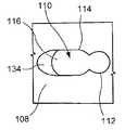
도 1은 본 발명의 예시적 실시예에 따른 골절술 플레이트의 평면도이다.
도 2는 도 1의 플레이트의 삼-부분 구멍의 확대 평면도이다.
도 3은 도 2의 세-부분 구멍의 확대 저면도이다.
도 4는 도 2의 A-A선을 따라 취한 확대 단면도이다.
도 5a는 제1 구성에서 그곳을 관통하여 뼈 고정 요소가 삽입된 도 2의 세-부분 구멍의 확대 평면도이다.
도 5b는 도 5a의 세-부분 구멍과 뼈 고정 요소의 확대 단면도이다.
도 6a는 제2 구성에서 그곳을 통해 삽입된 뼈 고정 요소를 포함하는 도 2의 세-부분 구멍의 확대 평면도이다.
도 6b는 도 6a의 세-부분 구멍과 뼈 고정 요소의 확대 단면도이다.
도 7a는 제3 구성에서 그곳을 통해 삽입된 뼈 고정 요소를 포함하는 도 2의 세-부분 구멍의 확대 평면도이다.
도 7b는 도 7a의 세-부분 구멍과 뼈 고정 요소의 확대 단면도이다.
도 8은 도 1의 플레이트의 제2 실시예의 평면도이다.
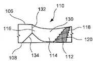
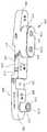
도 9는 본 발명의 대안적 실시예에 따른 골절술 플레이트의 사시도이다.
도 10은 도 9의 플레이트의 세-부분 구멍의 확대 사시도이다.
도 11은 본 발명의 예시적 실시예에 따른 드릴 템플릿의 사시도이다.
도 12는 본 발명의 예시적 실시예에 따른 가이드 와이어의 측면도이다.
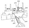
도 13은 본 발명의 예시적 실시예에 따른 쏘 가이드(saw guide)의 사시도이다.
도 14는 도 13의 쏘 가이드의 사시도이다.
도 15는 본 발명의 대안적 실시예에 따른 쏘 가이드의 측면도이다.
도 16은 본 발명의 예시적 실시예에 따른 쏘 블레이드(saw blade)의 사시도이다.
도 17은 본 발명의 외과적 기법의 예시적 실시예에 따라 뼈에 장착된 도 11의 드릴 템플릿의 사시도이다.
도 18은 도 17의 예시적 실시예에 따른 드릴 템플릿에 횡당 마킹들에 정렬된 도 16의 쏘 블레이드의 사이도이다.
도 19는 도 17의 예시적 실시예에 따라 그 위에 경사(oblique) 마킹들과 정렬되고 드릴 템플릿에 장착된 도 14의 쏘 가이드의 사시도이다.
도 20은 도 17의 예시적 실시예에 따른 뼈를 따라 위치된 도 1의 플레이트의 측면도이다.
도 21은 도 17의 예시적 실시예에 따라 플레이트 속으로 삽입된 제1 뼈 고정 요소의 측면도이다.
도 22는 도 17의 예시적 실시예에 따른 플레이트 속으로 삽입된 제2 뼈 고정 요소의 측면도이다.
도 23은 도 17의 예시적 실시예에 따른 플레이트에 삽입된 제3 뼈 고정 요소의 측면도이다.
도 24는 도 17의 예시적 실시예에 따른 뼈의 횡단 절단의 고정에 사용되는 도 1의 플레이트의 사시도이다.
도 25는 도 17의 예시적 실시예에 따른 뼈의 경사진 절단을 고정하는데 사용되는 도 1의 플레이트의 사시도이다.
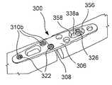
도 26은 본 발명의 다른 예시적 실시예에 따른 뼈 플레이트의 평면도이다.
도 27은 도 26의 예시적 실시예에 따라 뼈에 장착된 드릴 템플릿의 사시도이다.
도 28은 도 26의 예시적 실시예에 따른 쏘 가이드의 사시도이다.
도 29는 도 26의 예시적 실시예에 따른 뼈를 따라 위치된 뼈 플레이트의 사시도이다.
도 30은 도 26의 예시적 실시예에 따라 뼈의 압축을 도시하는 사시도이다.
도 31은 도 26의 뼈 플레이트에 삽입된 뼈 고정 요소의 사시도이다.
도 32는 도 26의 뼈 플레이트에 삽입된 다른 뼈 고정 요소들의 사시도이다.1 is a top view of a fracture plate according to an exemplary embodiment of the present invention.
Figure 2 is an enlarged plan view of the three-part hole of the plate of Figure 1;
Fig. 3 is an enlarged bottom view of the three-part hole of Fig. 2;
4 is an enlarged cross-sectional view taken along the line AA in Fig.
5A is an enlarged plan view of the three-part hole of FIG. 2 with a bone fixation element inserted therethrough in the first configuration. FIG.
Figure 5b is an enlarged cross-sectional view of the three-part hole and bone fixation element of Figure 5a.
FIG. 6A is an enlarged plan view of the three-part hole of FIG. 2 including a bone fixation element inserted therein through a second configuration. FIG.
Figure 6b is an enlarged cross-sectional view of the three-part hole and bone fixation element of Figure 6a.
FIG. 7A is an enlarged plan view of the three-part hole of FIG. 2 including a bone fixation element inserted through there in a third configuration. FIG.
Figure 7b is an enlarged cross-sectional view of the three-part hole and bone fixation element of Figure 7a.
Figure 8 is a plan view of a second embodiment of the plate of Figure 1;
Figure 9 is a perspective view of a fracture plate in accordance with an alternative embodiment of the present invention.
10 is an enlarged perspective view of the three-part hole of the plate of FIG.
11 is a perspective view of a drill template in accordance with an exemplary embodiment of the present invention.
12 is a side view of a guide wire according to an exemplary embodiment of the present invention.
Figure 13 is a perspective view of a saw guide according to an exemplary embodiment of the present invention.
Figure 14 is a perspective view of the saw guide of Figure 13;
15 is a side view of a saw guide in accordance with an alternative embodiment of the present invention.
16 is a perspective view of a saw blade in accordance with an exemplary embodiment of the present invention.
Figure 17 is a perspective view of the drill template of Figure 11 mounted to the bone in accordance with an exemplary embodiment of the surgical technique of the present invention.
Figure 18 is a cross-section of the saw blade of Figure 16 aligned with transverse markings on a drill template according to the exemplary embodiment of Figure 17;
Figure 19 is a perspective view of the saw guide of Figure 14 mounted on a drill template aligned with oblique markings thereon according to the exemplary embodiment of Figure 17;
Figure 20 is a side view of the plate of Figure 1 positioned along the bone according to the exemplary embodiment of Figure 17;
Figure 21 is a side view of a first bone fixation element inserted into a plate according to the exemplary embodiment of Figure 17;
Figure 22 is a side view of a second bone fixation element inserted into a plate according to the exemplary embodiment of Figure 17;
Figure 23 is a side view of a third bone fixation element inserted in a plate according to the exemplary embodiment of Figure 17;
Fig. 24 is a perspective view of the plate of Fig. 1 used for securing a transverse cut of a bone in accordance with the exemplary embodiment of Fig. 17;
Figure 25 is a perspective view of the plate of Figure 1 used to secure an oblique cut of a bone in accordance with the exemplary embodiment of Figure 17;
26 is a plan view of a bone plate in accordance with another exemplary embodiment of the present invention.
27 is a perspective view of a bone drill template according to an exemplary embodiment of FIG. 26;
28 is a perspective view of a saw guide in accordance with the exemplary embodiment of FIG. 26;
29 is a perspective view of a bone plate positioned along the bone in accordance with the exemplary embodiment of FIG. 26;
Figure 30 is a perspective view illustrating compression of the bones in accordance with the exemplary embodiment of Figure 26;
31 is a perspective view of a bone fixation element inserted into the bone plate of FIG. 26;
32 is a perspective view of other bone fixation elements inserted into the bone plate of FIG. 26;
본 발명은 이어지는 발명의 상세한 설명 및 첨부된 도면들을 참조할 때 더 잘 이해될 것이며, 유사한 구성요소들은 동일한 참조부호들이 부여되었다. 본 발명은 골절술을 수행하기 위한 시스템 및 방법에 관한 것이다. 특히, 예시적 실시예들은 골절술 플레이트 및 뼈의 절단 부분들의 정확한 정렬을 제공하기 위한 드릴 가이드와 같은 다른 장치들을 설명한다. 예시적 실시예들은 특별히 척골 골절술을 설명하고 있지만 본 발명은 다른 뼈들의 골절술을 위해 사용될 수도 있음을 당업자는 이해할 것이다.BRIEF DESCRIPTION OF THE DRAWINGS The invention will be better understood with reference to the following detailed description of the invention and the accompanying drawings, in which like elements have been given the same reference numerals. The present invention relates to a system and method for performing fracture. In particular, exemplary embodiments describe other devices such as a fracture plate and a drill guide to provide precise alignment of the cut portions of the bone. It will be appreciated by those skilled in the art that while the exemplary embodiments specifically describe ulnar fracture, the present invention may be used for fracture of other bones.
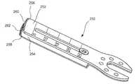
본 발명의 예시적 실시예에 따른 골절술 시스템은 도 1 내지 도 8에 도시된 바와 같은 골절술 플레이트(100), 도 11에 도시된 바와 같은 드릴 템플릿(template)(200), 및 도 16에 도시된 바와 같은 평행 쏘(parallel saw)(250)를 구비한다. 시스템은 도 13 및 도 14에 도시된 바와 같은 쏘 가이드(222) 및 도 12에 도시된 바와 같은 쏘 와이어(240)를 더 구비할 수도 있다. 플레이트(100)는 쏘(250)와 드릴 템플릿(200) 및/또는 가이드로서 쏘 가이드(222)를 사용하여 절단된 뼈(예, 척골)의 부분들을 고정하는데 사용될 수 있다. 드릴 템플릿(200)은 플레이트(100)의 개구들의 위치에 상응하는 구멍들을 가지며, 뼈를 절단하기 전에 뼈가 미리 천공되는 것을 허용한다. 드릴 템플릿(200)은 그 안에 정렬된 구멍들을 가진 미리 정의된 단축 길이들을 나타내는 마킹들을 포함하기 때문에, 절단 전 뼈의 표적 부분에 템플릿(200)이 배치될 때, 구멍들은 뼈의 부분들이 절단된 후 그리고 뼈의 나머지 부분들이 서로 접촉되어 압축되는 동안 플레이트의 구멍들의 위치들에 상응하게 될 위치들과 정렬된다. 즉, 플레이트(100)는 뼈의 필요한 방위에 위치되어, 압착 축(예, 뼈의 절단부들이 서로를 향해 이동하게 될 축)에 실질적으로 평행하게 연장한다. 초기 뼈 스크류들은 구멍들(138) 및/또는 구멍들(110)을 통해 삽입되어 뼈에 있는 상응하는 미리-천공된 구멍들로 삽입되어 뼈의 절단부들의 필요한 회전 정렬을 서로에 대해 유지하기 위해 뼈 부분들에 플레이트(100)를 유지하게 된다. 그러면, 가늘고 긴 부분(142)의 끝단에 삽입된 초기 스크류는 절단된 뼈 조각들의 서로를 향한 압착이 필요한 회전 정렬을 유지하기 위한 이러한 압착 동안 가늘고 긴 부분들(142) 내부에 세로 방향으로 자유롭게 움직일 수 있다. 쏘(250)는 사용자가 단일의 정교한 액션으로 뼈의 필요한 부분을 제거하여 동시에 2개의 평행한 절단부를 만들 수 있도록 하는 2개의 평행한 블레이드들(252)(254)을 포함한다.A fracture system according to an exemplary embodiment of the present invention includes a
도 1에 도시된 바와 같이, 플레이트(100)는 근위단(102)으로부터 원위단(104)까지 길이 방향으로 연장하고, 수술 위치에 있을 때 뼈로부터 떨어져서 면하는 제1 표면(106)과 수술 위치에 있을 때 뼈에 면하는 제2 표면(108)을 포함한다. 플레이트(100)는 세-부분 조합 구멍(110), 두-부분 조합 구멍(138) 및 록킹 구멍(148)을 포함하는 다수의 구멍들을 포함한다. 플레이트(100)는 주변 조직에 대한 자극을 방지하기 위해 라운드진 가장자리들을 따라 테이퍼 및/또는 라운드진 근위단(102)과 원위단(104)을 가진 높이가 낮은 구조(low profile)을 포함할 수 있다. 플레이트(100)는 길이 방향 축에 대해 대략 4°각도에서 미리-굴곡됨으로써 반대편 피질에서 압착을 얻을 수 있다. 플레이트(100)는 예를 들어, 스테인리스 스틸, 티타늄 등을 포함하는 그 어떤 생체적합성 물질로 형성될 수 있다.As shown in Figure 1, the
바람직한 실시예에 있어서, 플레이트(100)는 플레이트(100)의 길이를 따라 그 중간 지점을 실질적으로 수직으로 연장하는 대칭축(150)에 대칭이다. 따라서, 플레이트(100)는 대칭축(150)의 원위 방향의 원위부(154)에 실질적으로 대칭 및/또는 거울상(mirror image)이 되는 대칭축의 근위 방향의 근위부(152)를 포함한다. 플레이트(100)가 뼈의 양쪽 방향의 어디에도 위치될 수 있도록 플레이트(100)가 대칭 구조를 가지는 것은 당업자가 충분히 이해할 것이다. 플레이트(100)가 뼈를 따라 어느 한쪽 방향으로 위치될 수 있기 때문에, 본 명세서에서 사용된 "근위" 및 "원위"라는 용어는 플레이트(100)의 특정 끝단을 의미하지는 않지만, 수술 위치에서, 뼈의 근위단과 원위단 쪽을 각각 향하는 끝단들을 지칭하는데 사용된다. 바람직한 실시예에 있어서, 플레이트(100)는 2개의 세-부분 구멍들(110), 2개의 두-부분 구멍들(138) 및 2개의 록킹 구멍들(148)을 포함한다. 특히, 제1 세-부분 구멍(110a), 제1 두-부분 구멍(138a) 및 제1 록킹 구멍(148a)은 플레이트(100)의 근위부(152)를 따라 위치될 수 있는 반면 제2 세-부분 구멍(110b), 제2 두-부분 구멍(138b) 및 제2 록킹 구멍(148b)은 플레이트(100)의 원위부(154)를 따라 상응하게 대칭되는 위치에 위치될 수 있다. 본 실시예에 있어서, 제1 세-부분 구멍(110a)과 제2 세-부분 구멍(110b)은 대칭축(150)에 가장 가깝게 위치되는 한편 제1 록킹 구멍(148a)과 제2 록킹 구멍(148b)은 대칭축(150)으로부터 가장 멀고 각각 근위단(102)과 원위단(104)에 가장 가깝게 위치된다. 그러나, 이러한 형태의 그 어떤 다른 수의 구멍들도 본 발명의 시사점으로부터 벗어나지 않는 범위 내에서 주어진 시술의 요구조건을 만족하도록 채택될 수 있음을 당업자는 이해할 것이다.In a preferred embodiment, the
도 2 내지 도 4에 도시된 바와 같이, 세-부분 구멍(110)은 제1 부분(112), 제2 부분(114) 및 제3 부분(116)을 포함한다. 제1 부분(112)과 제3 부분(116)은 제2 부분(114)에 의해 연결된 상태에서 제1 부분(112)과 제3 부분(116)은 세-부분 구멍(110)의 대향되는 길이 방향 끝단들을 구획한다. 제1 부분(112)은 제1 표면(106)으로부터 제2 표면(108)을 향해 방사상으로 실질적으로 원뿔 형태로 테이퍼지는 부분 원형 개구에 의해 구획된다. 제1 부분(112)은 그 내면(120)을 따라 형성된 나사산(118)을 포함하고, 도 5a 및 도 5b에 도시된 바와 같이, 제1 부분(112)의 중앙축을 따라 그곳을 관통하는 제1 뼈 고정 요소(122)(예, 록킹 스크류)를 수납하도록 구성된다. 당업자에 의해 이해되는 바와 같이, 나사산(118)은 제1 뼈 고정 요소(122)의 헤드부(124)가 중앙축을 기준으로 그 속으로 회전할 때 헤드부(124)의 상응하는 나사산과 결합한다.2 through 4, the three-
제2 부분(114)과 제3 부분(116)은, 스크류 헤드의 중요성 없이 플레이트(100)가 위치된 뼈의 표면에 실질적으로 직교하는 축에 대해 0°내지 45°의 그 어떤 필요한 각도에서 그곳을 관통하는 제2 뼈 고정 요소(126)(예, 코텍스 스크류)를 수납하도록 구성된 세-부분 구멍(110)의 실질적으로 가늘고 긴 부분을 함께 구획한다. 제2 부분(114)은 제1 부분(112)과 제3 부분(116) 사이에서 연장하고, 제1 표면(106)으로부터 제2 표면(108)까지 테이퍼진 반경 방향으로 대향되는 굴곡 벽들(130)을 포함한다. 도 6a 및 도 6b에 도시된 바와 같이, 제2 뼈 고정 요소(126)는 제2 뼈 고정 요소(126)의 상응하는 모양(예, 구형)의 헤드부(128)가 제2 부분(114)의 굴곡 벽들(130) 사이에 안착 될 때까지 중앙 축을 따라 제2 부분(114) 속으로 삽입될 수 있다. 굴곡 벽들(130)은 헤드부(128)를 수납하는 모양이고 헤드부가 제1 표면(106)을 통과하여 연장하는 것을 방지한다. 제3 부분(116)은 제2 부분(114)과 중첩될 수 있고, 그곳으로부터 매끄럽게 천이됨으로써 제2 뼈 고정 요소(126)가 그 중앙축에 대해 45°까지 그곳을 통해 삽입될 수 있다. 제3 부분(116)은 제1 표면(106)으로부터 제1 내벽(132)의 뼈를 면하는 끝단으로부터 제2 표면(108)까지 연장하는 제2 내벽(134)까지 플레이트(100) 속으로 연장하는 제1 내벽(132)을 포함한다. 제1 내벽(132)은 그것에 대해 필요한 각도에서 헤드부(128)를 수용하기 위해 제2 부분(114)의 굴곡 벽들(130)을 가진 연속적인 표면을 형성한다. 제2 내벽(134)은 최대 각도(angulation)까지 그 어떤 필요한 각도에 제2 뼈 고정 요소(126)의 샤프트부(136)를 수용하기 위해 제1 내벽(132)으로부터 제2 표면(108)까지 방사상의 외측으로 연장한다. 예를 들어, 본 실시예에 있어서, 도 7a 및 도 7b에 도시된 바와 같이, 제2 내벽(134)은 45°각도에서 플레이트(100)의 세로축을 따라 제1 내벽(132)으로부터 외측으로 연장되어, 제2 뼈 고정 요소가 그곳을 통해 뼈의 표면에 대해 90°와 45°각도 사이에서 삽입되는 것을 허용한다. 아래에서 더욱 상세히 설명되는 바와 같이, 뼈가 횡방향에 대해 각을 형성하는 컷(cuts)을 통해 짧아질 때, 구멍(110)의 제3 부분(116)에서 제2 뼈 고정 요소의 최대 각도보다 더 크지 않는 각도에서 컷을 만드는 것이 바람직하다. 이것은 사용자가 뼈의 컷에 직교하는 축을 따라 그곳을 통해 제2 뼈 고정 요소를 삽입하는 것을 허용한다.The
두-부분 구멍(138)은 제1 부분(140)과 제2 부분(142)을 포함한다. 본 실시예에 있어서, 제1 부분(140)은 세-부분 구멍(110)의 제1 부분(112)과 실질적으로 유사하고 중앙 축을 따라 제1 뼈 고정 요소(122)를 수납하도록 구성되어 나사산(144)을 통해 제1 뼈 고정 요소(122)의 헤드부(124)와 결합한다. 두-부분 구멍(138)의 제2 부분(142)은 제1 표면(106)으로부터 제2 표면(108) 쪽으로 테이퍼진 굴곡 내벽(146)을 포함하는 실질적으로 가늘고 긴 슬롯을 구획한다.The two-
록킹 구멍(148)은 록킹 스크류와 같은 뼈 고정 요소의 나사산이 형성된 헤드부와 결합하기 위해 그 내면을 따라 형성된 나사산(미도시)을 포함한다. 록킹 구멍들(148)은 플레이트(100)를 뼈에 위치시켜 그곳에 대해 플레이트(100)를 고정시키기 위해 플레이트(100)의 근위단(102)과 원위단(104)에 가깝게 위치될 수 있다. 록킹 구멍(148)의 제1 부분은 플레이트(100) 속으로 연장하여 록킹 스크류의 헤드부의 모양에 상응하도록 제1 표면(106)으로부터 제2 부분(108) 쪽으로 내측으로 방사상으로 테이퍼진다.The
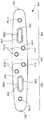
플레이트(100)는 상술한 구멍들(110)(138)(148)의 그 어떤 조합들, 바람직하게 대칭 형태를 포함하는 다양한 길이로 제조될 수 있음을 당업자는 이해할 것이다. 예를 들어, 도 1에 도시된 바와 같이, 보다 짧은 6-구멍 플레이트(100)는 플레이트(100)의 길이를 따라 대칭 패턴으로 위치된 2개의 세-부분 조합 구멍들(110a)(110b), 2개의 두-부분 조합 구멍들(138a)(138b), 및 2개의 록킹 구멍들(148a)(148b)을 포함할 수 있다. 도 8에 도시된 바와 같이, 보다 긴 8-구멍 플레이트(100)에 있어서, 플레이트(100)는 플레이트(100)의 근위부(152)를 따라 배치된 가늘고 길지 않는 두-부분 구멍(158a)과, 원위부(154)를 따라 상응하게 대칭되는 위치에 위치된 가늘고 길지 않는 두-부분 구멍(158b)을 포함한다. 가늘고 길지 않는 두-부분 구멍들(158a)(158b)의 각각은 두-부분 구멍(138)과 실질적으로 유사한 제1 부분(160)과 제2 부분(162)을 포함할 수 있다. 특정한 플레이트의 의도된 용도에 따라, 구멍들은 그 길이를 따라 대칭적으로 분포되지 않을 수도 있음을 당업자는 이해할 것이다.It will be appreciated by those skilled in the art that the
도 9 및 도 10에 도시된 바와 같이, 대안적 실시예에 따르면, 플레이트(100)와 실질적으로 유사한 플레이트(100')는 세-부분 조합 구멍(110')을 포함한다. 플레이트(100)와 유사하게, 조합 구멍(110')은 제1 부분(112'), 제2 부분(114'), 및 제3 부분(116')을 포함한다. 그러나, 플레이트(100)의 구멍(110)과 달리, 제2 부분(114')과 제3 부분(116') 사이에는 매끄러운 천이가 마련되지 않는다. 대신에, 제2 부분(114')과 제3 부분(116')은 분명하게 분리된 라운드진 구멍들에 의해 구획됨으로써, 뼈 고정 요소는 제2 구멍(114')과 제3 구멍(116') 중 어느 하를 통해 삽입될 수 있을 뿐이다. 따라서, 뼈 고정 요소는 0°각도에서 제2 부분(114')의 중앙축과 세-부분 구멍(100')의 중앙축에 대해 소정 각도(예, 45°)로 설정된 제3 부분(116')의 미리 정의된 삽입 축의 어느 하나만을 따라 그 속으로 삽입될 수 있다. 구멍(110')은 제2 부분(114')과 제3 부분(116') 사이의 각도에서 뼈 고정 요소의 삽입을 허용하지 않는다.As shown in FIGS. 9 and 10, according to an alternative embodiment, the plate 100 ', which is substantially similar to the
도 11에 도시된 바와 같이, 드릴 템플릿(200)은 근위단(202)으로부터 원위단(204)까지 길이 방향으로 연장할 수 있고, 수술 위치에 있을 때 뼈로부터 떨어져서 면하는 제1 표면(206)과, 수술 위치에 있을 때, 뼈에 면하는 제2 표면(208)을 포함한다. 드릴 템플릿(200)과 관련한 근위 및 원위의 용어는 예시적인 시술의 필요한 방위에 있어서 드릴 템플릿(200)의 방위에만 상응하는 것임을 당업자는 이해할 것이다. 다른 시술들에서, 드릴 템플릿의 구성요소들의 방위는 뒤바뀔 수 있다. 드릴 템플릿(200)은 제1 표면(206)으로부터 제2 표면(208)까지 드릴 템플릿(200)을 통해 연장하는 다수의 개구들(210)을 포함한다. 드릴 템플릿(200)은 뼈를 절단하기 전에 사전-천공을 허용하기 위해 다양한 종류의 미리 정의된 단축 길이들(예, 2.0, 2.5, 3.0, 4.0 및 5.0mm)로 제조될 수 있다. 따라서, 개구들(210)의 각각은 세-부분 구멍들(100)과 두-부분 구멍(138)의 어느 하나의 위치에 상응하는 드릴 템플릿(200)을 따라 위치된다. 바람직한 실시예에 있어서, 드릴 템플릿(200)은 3개의 개구들(210)을 포함한다. 개구들(210)의 2개는 드릴 템플릿(200)의 원위단(204)을 향해 위치되는 한편 개구들(210)의 하나는 근위단(202) 즉, 2개의 개구들(210)로부터 천공될 구멍들이 형성될 뼈의 부분에 상응하는 위치를 향하여 위치된다. 예를 들어, 3개의 개구들(210)의 제1 개구(210a)는 플레이트(100)의 원위부(154)를 따르는 세-부분 구멍(110)의 위치에 상응하는 반면 개구들(210)의 제2 개구(210b)는 원위부의 두-부분 구멍(138b)의 위치에 상응한다. 제3 개구(210c)는 근위부(152)를 통해 연장하는 두-부분 구멍(138a)의 근위단(146)에 상응한다.11, the
개구들(210)은 도 12에 도시된 바와 같은 가이드 와이어(240) 및/또는 그곳을 관통하는 드릴 팁(tip)을 수용하는 크기와 모양을 가진다. 드릴 템플릿(200)은 제1 표면(206)으로부터 개구들(210)의 각각을 기준으로 연장하여 개구들(210)에 삽입되는 가이드 와이어(240)의 길이를 따라 더 큰 지지력을 허용하는 돌기들(212)을 더 포함한다. 가이드 와이어(240)는 그 원위단에서 드릴 팁(242)을 포함할 수 있으므로, 개구들(210)을 관통하여 가이드 와이어(240)의 삽입에 의해 뼈에 구멍들이 천공될 수 있다. 드릴 템플릿(200)은 제2 표면(108)을 따라 함몰된 언더컷(214)을 더 포함할 수 있으므로, 드릴 템플릿(200)은 쏘(saw)(250)를 드릴 템플릿(200)에 접촉시키지 않으면서 그 위에 위치되어 있는 동안 뼈를 완전히 제거한다. 언더컷(214)의 측면에서, 드릴 템플릿(200)은 절단되어 질 뼈의 위치를 나타내는 마킹들(218)(220)을 포함한다. 예를 들어, 제1 마킹(218)은 실질적으로 횡단 컷(예, 뼈의 세로축에 실질적으로 수직되는)을 나타내는 반면 제2 마킹(220)은 뼈의 세로축에 대해 필요한 각도(예, 45°)의 컷을 나타낸다. 따라서, 드릴 템플릿(200)은 쏘(250)를 위한 가이드를 제공할 수 있으므로, 뼈의 횡단 컷을 제공하기 위해 사용될 때 블레이드가 마킹(218)과 실질적으로 정렬되어 있기 때문에 별도의 쏘 가이드가 불필요할 수도 있다. 쏘 가이드(222)와 결합하여 드릴 템플릿(200)을 사용할 필요가 있는 경우, 아래에서 더 상세히 설명되는 바와 같이, 드릴 템플릿(200)은 쏘 가이드(222)의 일 부분을 수납하기 위해 제1 표면(206)을 따르는 그루브(215)를 포함할 수 있다.The
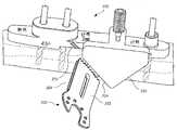
드릴 템플릿(200)이 제2 마킹(220)을 통해 경사 컷(oblique cut)을 제공하는데 사용될 경우, 시스템은 도 13 및 도 14에 도시된 바와 같이, 경사각 마킹을 따라 쏘(250)를 가이드하기 위해 드릴 템플릿(200)에 장착될 수 있는 쏘 가이드(222)를 더 구비할 수 있다. 쏘 가이드(222)는 적어도 하나의 각진 표면(224)을 포함할 수 있고, 쏘 가이드(222)가 드릴 템플릿(200)에 장착될 때 제2 마킹(220)에 정렬됨으로써 쏘(250)가 각진 표면을 따라 미끄러지면 미리 정의된 경사진 각도(예, 45°)로 뼈를 절단할 것이다. 그러나, 바람직한 실시예에 있어서, 쏘 가이드(222)는 대칭적일 수 있는 2개의 각진 표면(224)을 포함할 수 있으므로, 쏘 가이드(222)는 드릴 템플릿(200)에 장착되어 쏘 가이드(222)의 장착에 따라 드릴 템플릿(200)의 양측에 표시된 마킹(220)에서 경사진 각도로 뼈가 절단되는 것을 허용한다. 쏘 가이드(222)는 그곳으로부터 연장하는 부착 요소(228)를 포함할 수 있으므로 부착 요소(228)는 그루브(215) 내부에 수납되어 절단하는 동안 쏘 가이드(222)의 회전 이동을 방지한다. 부착 요소(228)는 드릴 템플릿(200)의 제1 표면(206)에 연결될 부착 요소(228)의 개구(230)를 통해 삽입되는 스크류(226)를 통해 드릴 템플릿의 제1 표면의 그루브(215) 내부에 장착될 수 있다. 쏘 가이드(222)는 드릴 템플릿(200)에 부착되어야 하기 때문에 각진 표면(224)은 드릴 템플릿(200)의 마킹들(220)과 정렬된다. 대안적 실시예에 있어서, 쏘 가이드(222')는 도 15에 도시된 바와 같이 핀(226')을 통해 드릴 템플릿(200)의 측면(216)에 장착될 수 있으므로, 각진 표면(224')은 제2 마킹들(220)과 정렬될 수 있다.When the
도 16에 도시된 바와 같이, 쏘(250)는 제1 블레이드(252)와 제2 블레이드(254)를 구비하고, 그들 각각은 실질적으로 편평하고 서로에 대해 고정되기 때문에 제1 블레이드(252)와 제2 블레이드(254)는 실질적으로 서로 평행하다. 당업자에 의해 이해되는 바와 같이, 제1 및 제2 블레이드들(252)(254)은 각각 치차(260)(262) 또는 뼈의 절단을 용이하게 하는 다른 구성들을 포함할 수 있다. 쏘(250)는 횡단 컷과 경사 컷 모두를 위해 다양한 그 어떤 크기로 제조될 수 있으며, 제1 및 제2 블레이드들(252)(254)은 설명된 드릴 템플릿(200)의 미리 정의된 단축 길이에 상응하는 미리 정의된 간격에 의해 마킹들(218)(220)을 통하여 서로 분리된다. 평행한 제1 및 제2 블레이드들(252)(254)은 쏘(250)를 구동하는 진동 동작을 통한 단일의 절단 동작에 의해 뼈의 정교한 평행 절단을 제공한다. 쏘(250)는 제1 및 제2 블레이드들(252)(254)을 뼈를 관통하여 박아넣음으로써 그 세로축에 직교되도록 진동될 수 있다.As shown in Figure 16, the
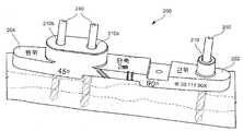
예시적인 외과적 수술법에 따르면, 도 17 내지 도 23에 도시된 바와 같이, 컷(cut)이 뼈에 만들어짐으로써, 뼈는 플레이트(100)를 이용하여 고정될 수 있다. 도 17에 도시된 바와 같이, 드릴 템플릿(200)은 뼈를 따라 바람직하게, 뼈(예, 척골)의 1/3 원위 방향의 중간의 내측 가장자리를 따라 위치될 수 있으므로, 드릴 템플릿(200)의 원위단(204)은 뼈의 원위단과 면하고 근위단(202)은 뼈의 근위단에 면한다. 드릴 템플릿(200)은 2개 또는 그 이상의 개구들(210)을 통해 삽입된 가이드 와이어(240)를 통해 뼈에 고정될 수 있다. 가이드 와이어(240)는 드릴 팁(242)을 통해 뼈를 따르는 상응한 위치에서 구멍을 천공하는 방식으로 삽입된다. 이러한 사전-천공(pre-drilling)은 뼈가 전달된 후 뼈의 적정한 정렬을 용이하게 하는 것을 당업자는 이해할 것이다. 도 18에 도시된 바와 같이, 사용자가 뼈를 횡단으로 관통하는 컷을 만들기 원하는 경우, 쏘(250)의 제1 및 제2 블레이드들(252)(254)은 드릴 템플릿(200)에 표시된 제1 마킹(218)과 정렬된다. 그러나, 도 19에 도시된 바와 같이, 사용자가 경사 컷을 만들기 원하는 경우, 사용자는 각진 표면(224)을 제2 마킹(220)에 정렬시켜 쏘 가이드(222)를 드릴 템플릿(200)에 부착함으로써 쏘(250)는 그곳을 따라 미끄러질 수 있다.According to an exemplary surgical procedure, as shown in Figs. 17-23, a cut is made on the bone, so that the bone can be fixed using the
쏘(250)는 뼈 속으로 압력을 가해서 뼈에 평행한 횡단 및/또는 경사 컷을 만들 수 있다. 뼈가 절단되고 뼈의 절단부가 제거되고 나면, 드릴 템플릿(200)이 제거되는 반면, 가이드 와이어(240)의 뼈에 대한 삽입은 유지된다. 도 20에 도시된 바와 같이, 드릴 템플릿(200)을 제거하고 나면, 플레이트(100)는 가이드 와이어(240) 위에서 뼈로 미끄러짐으로써 가이드 와이어들(240)의 각각은 플레이트의 구멍들(110)(138) 중 상응하는 어느 하나에 수납된다. 도 21에 도시된 바와 같이, 초기에 개구(210a)에 삽입된 가이드 와이어(240)는 플레이트(100)의 세-부분 구멍(110b)에 상응하게 된 후 제거됨으로써 첫 번째 제2 뼈 고정 요소들(126)이 그곳을 통해 삽입될 수 있다. 도 22에 도시된 바와 같이, 가이드 와이어(240)는 초기에 개구(210b)를 통해 삽입된 후 제거되기 때문에, 두 번째 제2 뼈 고정 요소들(126)이 플레이트(100)의 원위부(154)를 따라 상응하는 두-부분 구멍(138b) 속으로 삽입된다.The
결과적으로, 도 23에 도시된 바와 같이, 마지막 가이드 와이어(240)가 제거되고, 세 번째 제2 뼈 고정 요소들(126)은 플레이트(100)의 근위부(152)의 두-부분 구멍(138b)의 근위단(156) 속으로 그리고 뼈에 미리-천공된 구멍을 통해 삽입된다. 압착이 뼈에 가해지면 뼈의 두 부분들이 서로 필요한 공간적 관계(예, 필요한 회전 정렬로 서로 접촉하는)에 있을 때까지 뼈의 근위부는 절단 뼈의 원위부를 향해 제거된다. 뼈의 근위부는 플레이트(100)의 근위부(152)의 두-부분 구멍(138a)의 가늘고 긴 제2 부분(142)을 통해 근위단(156)으로부터 뼈 고정 요소의 슬라이딩을 통해 플레이트(100)에 대해 제거될 수 있다. 그러면, 플레이트(100)의 나머지 구멍을 통해 뼈 속으로 뼈 스크류를 삽입함에 의해 뼈의 고정이 완료된다. 예를 들어, 도 24에 도시된 바와 같이, 제1 뼈 고정 요소(122)(예, 록킹 스크류)는 록킹 구멍들(148a)(148b) 속으로 삽입될 수 있고, 제1 및 제2 뼈 고정 요소들(122)(126)(예, 록킹 스크류, 코텍스 스크류)의 어느 하나는 세-부분 구멍(110a) 속으로 삽입될 수 있다. 도 25에 도시된 바와 같이, 뼈에 경사 컷이 만들어진 경우, 제2 뼈 고정 요소(126)는 그 중앙축에 대한 각도에서 세-부분 구멍(110a)을 통해 삽입될 수 있으므로, 샤프트부(136)는 뼈의 경사지게 절단된 표면들을 통해 연장한다.23, the
도 26 내지 도 32에 도시된 바와 같이, 본 발명의 제2 예시적 실시예에 따르면, 도 26에 도시된 플레이트(300)는 드릴 가이드(400)와 쏘 블레이드(450)를 사용하여 절단된 뼈의 부분들을 고정하는데 사용될 수 있다. 도 26에 도시된 바와 같은 플레이트(300)는 전술한 플레이트(100)와 실질적으로 유사하고, 근위단(302)으로부터 원위단(304)까지 길이 방향으로 연장한다. 플레이트(100)와 유사하게, 바람직한 실시예에 있어서, 플레이트(300)는 대칭축(350)을 기준으로 서로에 대해 실질적으로 대칭되는 모양일 수 있는 근위부(352)와 원위부(354)를 포함한다. 그러나, 플레이트(300)는 세-부분 구멍과 두-부분 구멍을 포함하지는 않는다. 대신에, 플레이트(300)는 제1 표면(306)으로부터 제2 표면(308)까지 근위부(352)와 원위부(354) 모두를 따라 그곳을 통해 연장하는 다수의 록킹 구멍들(310)을 포함한다. 예를 들어, 근위부(352)는 다수의 록킹 구멍들(310a)을 포함할 수 있고 원위부(354) 역시 다수의 록킹 구멍들(310b)을 포함할 수 있다. 그러나, 도 26에 도시된 바와 같이, 다수의 록킹 구멍들(310a)(31b)은 근위부와 원위부를 따라 서로에 대한 거울상일 필요는 없다. 부가적으로, 근위부(352)와 원위부(354)는 각각 가늘고 긴 구멍(338a)(338b)을 포함할 수 있다. 26 to 32, in accordance with a second exemplary embodiment of the present invention, the
록킹 구멍들(310)은 록킹 구멍들(148)과 실질적으로 유사할 수 있고, 뼈 고정 요소의 나사산이 형성된 헤드부와 결합하기 위해 그 내면을 기준으로 연장하는 나사산(318)을 포함한다. 가늘고 긴 구멍(338)은 길이 방향으로 가늘고 길게 되어 있으며, 제1 표면(306)으로부터 제2 표면(308)을 향해 테이퍼지는 내면(346)을 포함한다. 내면(346)은 예를 들어, 코텍스 스크류와 같은 뼈 고정 요소의 상응하는 모양의 헤드부를 수납하도록 실질적으로 구형 모양일 수 있다.The locking holes 310 may be substantially similar to the locking holes 148 and include
도 27에 도시된 바와 같이, 드릴 템플릿(400)은 전술한 드릴 템플릿(200)과 실질적으로 유사하고, 근위단(402)으로부터 원위단(404)까지 연장하고, 원위부(354)의 록킹 구멍들(310b)과 근위부(352)의 가늘고 긴 구멍(338a)의 위치들에 상응하는 개구들(410)을 포함한다. 드릴 템플릿(200)과 유사하게, 드릴 템플릿(400)은 절단된 후, 플레이트(300)가 뼈의 절단된 부분들 위의 필요한 위치에 있을 때, 플레이트(300)를 관통하여 연장하는 구멍들(310a)(310b)이 위치될 상응하는 위치들에서 개구들(410)을 통해 삽입되는 가이드 와이어 또는 드릴 팁(440)을 사용하여 뼈에 구멍을 미리-천공하기 위해 뼈를 따라 위치될 수 있다. 쏘(250)와 실질적으로 유사한 쏘(450)는 전술한 것과 동일한 방식으로 뼈에 대해 위치될 수 있는 쏘 가이드(422)를 사용하여 뼈에 평행한 횡단 컷 및/또는 경사 컷을 만들기 위해 계속해서 사용될 수 있다. 도 28에 도시된 바와 같이, 쏘 가이드(422)는 그곳을 통해 실질적으로 횡단 컷을 만들기 위해 뼈에 대해 위치될 수 있다. 대안적으로, 쏘(422)는 각진 표면(424)을 포함함으로써 쏘(450)는 뼈의 축에 대해 미리 정의된 경사진 각도를 따라 뼈를 절단하기 위해 각진 표면에 대해 이동될 수 있다.27, the
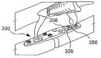
본 발명의 제2 실시예의 시스템에 따른 수술법은 전술한 수술법과 실질적으로 유사하다. 뼈를 절단한 후, 드릴 템플릿(400)이 제거되고 플레이트(300)는 가이드 와이어들(440) 위로 미끄러져서 뼈를 따라 위치된다. 대안적으로, 가이드 와이어들 및/또는 드릴 팁(440)은 뼈에 구멍들이 미리-천공된 후 제거될 수 있다. 도 29에 도시된 바와 같이, 가이드 와이어들(440)을 제거한 후, 제1 뼈 고정 요소들(322)(예, 록킹 헤드 스크류들)은 원위부(354)를 따라 록킹 구멍들(310b) 속으로 삽입되고 제2 뼈 고정 요소(326)(예, 코텍스 스크류)는 근위부(352)의 가늘고 긴 구멍(338a)의 근위단(356) 속으로 삽입될 수 있다. 그러면, 도 30에 도시된 바와 같이, 절단된 뼈의 근위부와 원위부가 서로에 대해 필요한 공간적 관계가 될 때까지 뼈에 압착을 가해서 뼈의 근위부를 그 원위부로 이동시킨다. 이러한 이동 동안, 가늘고 긴 구멍(338a)의 근위단(356)을 통해 삽입되었던 뼈 고정 요소(326)는 가늘고 긴 구멍(338a) 내부에서 그 원위단(358) 쪽으로 원위적으로 미끄러진다. 도 31에 도시된 바와 같이, 추가적인 압착을 위해, 제2 뼈 고정 요소(326)는 가늘고 긴 구멍(338a)의 근위단(356) 속으로 삽입될 수 있다. 도 32에 도시된 바와 같이, 추가적인 고정을 제공하기 위해, 추가적인 뼈 고정 요소들(322)은 나머지 록킹 구멍들(310a) 속으로 삽입될 수 있다.The operation method according to the system of the second embodiment of the present invention is substantially similar to the above-described operation method. After cutting the bone, the
본 발명의 정신 또는 범위를 벗어나지 않는 한 본 발명의 구조 및 방법에 대한 다양한 변형 및 변화가 가능하다는 사실은 당업자에게 명백하다. 따라서, 본 발명은 첨부된 특허청구범위와 그 균등물의 범위 내에서 본 발명의 다양한 변화와 변형을 모두 커버하는 것을 의도한다.
It will be apparent to those skilled in the art that various modifications and variations can be made in the structure and method of the present invention without departing from the spirit or scope of the invention. Accordingly, the present invention is intended to cover various modifications and variations of the present invention within the scope of the appended claims and their equivalents.
100...플레이트 110...세-부분 조합 구멍
112...제1 부분 114...제2 부분
116...제3 부분 122...1 뼈 고정 요소
126...제2 뼈 고정 요소 138...두-부분 조합 구멍
148...록킹 구멍 150...대칭축
200...드릴 템플릿 210...개구
214...언더 컷 215...그루브
218...제1 마킹 220...제2 마킹
222...쏘 가이드 224...각진 표면
240...가이드 와이어 250...쏘(saw)
252...제1 블레이드 254...제2 블레이드100 ...
112 ...
116 ...
126 ... second
148 ... locking
200 ...
214 ... undercut 215 ... groove
218 ... first marking 220 ... second marking
222 ... saw
240 ...
252 ...
Claims (23)
Translated fromKorean상기 플레이트의 상기 근위부를 관통 연장하는 제1 세-부분 조합 구멍(first 3-part combination hole) 및 상기 플레이트의 상기 원위부를 관통 연장하는 제3 세-부분 조합 구멍; 및
상기 플레이트의 상기 근위부를 관통 연장하는 제1 두-부분 조합 구멍(first 2-part combination hole) 및 상기 플레이트의 상기 원위부를 관통 연장하는 제2 두-부분 조합 구멍을 구비하고;
세-부분 조합 구멍들 각각의 제1 부분은 나사산이 형성되어 있고 뼈 고정 요소의 나사산이 형성된 헤드부와 결합하도록 구성되어 있고, 세-부분 조합 구멍들 각각의 제2 부분은 상기 플레이트가 필요한 방위로 뼈에 장착될 때 뼈의 길이 방향 축에 직교하는 축을 따라 뼈 고정 요소를 수납하도록 구성되어 있고, 세-부분 조합 구멍들 각각의 제3 부분은 상기 플레이트가 필요한 방위로 뼈에 장착될 때 상기 뼈의 상기 길이 방향 축에 대해 비-직교 각도로 상기 가늘고 긴 본체의 상기 원위단을 향해 상기 제2 표면으로부터 연장하는 스크류 축을 구획하도록 되어 있고;
두-부분 조합 구멍들 각각의 제1 부분은 뼈 고정 요소의 나사산이 형성된 헤드부를 수납하여 결합되도록 구성되어 있고, 두-부분 조합 구멍들 각각의 제2 부분은, 상기 제1 두-부분 조합 구멍과 제2 두-부분 조합 구멍 및 상기 제1 세-부분 조합 구멍이 각각의 뼈 고정 요소들과 결합할 때, 관통하는 뼈 고정 요소를 수납하기 위해 상기 플레이트의 길이 방향 축을 따라 연장하는 가늘고 긴 슬롯을 구획하고,
상기 플레이트는 상기 제2 두-부분 조합 구멍이 관통 수납되는 상기 뼈 고정 요소에 대해 길이 방향 축을 따라 슬라이딩되도록 구성되고,
상기 제1 두-부분 조합 구멍 및 상기 제2 두-부분 조합 구멍은 상기 대칭 축으로부터 등거리인, 뼈 플레이트.
A first surface extending from the proximal end to the distal end and facing away from the bone to which the plate will be mounted when in the operative position and a second surface facing the bone when in the operative position, An elongated body having a proximal portion symmetrical to the proximal portion with respect to a symmetry axis orthogonal to the axis;
A first three-part combination hole extending through the proximal portion of the plate and a third three-part combination hole extending through the distal portion of the plate; And
A first two-part combination hole extending through the proximal portion of the plate and a second two-part combination hole extending through the distal portion of the plate;
The first portion of each of the three-part combination holes is configured to engage with the threaded head portion of the bone fixation element and the second portion of each of the three- Wherein the third portion of each of the three-part combination holes is configured to receive the bone fixation element along an axis perpendicular to the longitudinal axis of the bone when mounted to the bone, Such that it defines a screw axis extending from the second surface toward the distal end of the elongate body at a non-orthogonal angle relative to the longitudinal axis of the bone;
Wherein the first portion of each of the two-part combination holes is configured to receive and receive the threaded head portion of the bone fixation element and the second portion of each of the two- And a second elongated slot extending along the longitudinal axis of the plate for receiving a bone fastening element passing therethrough when the first elongated slot and the second elongated slot are in engagement with respective bone fastening elements, Respectively,
Wherein the plate is configured to slide along a longitudinal axis with respect to the bone anchoring element through which the second two-part combination hole is inserted,
Wherein the first two-part combination aperture and the second two-part combination aperture are equidistant from the symmetry axis.
상기 가늘고 긴 본체의 원위부를 관통 연장하는 제1 록킹 구멍을 더 구비하고,
상기 제1 록킹 구멍은 뼈 고정 요소의 나사산이 형성된 헤드와 나사 결합하기 위해 내면을 따라 형성된 나사산을 구비하는, 뼈 플레이트.
The method according to claim 1,
Further comprising a first locking hole extending through the distal portion of the elongate body,
Wherein the first locking aperture comprises threads formed along an inner surface for threading with a threaded head of a bone fixation element.
상기 제1 세-부분 조합 구멍의 상기 제3 부분은 상기 제1 표면으로부터 상기 제2 표면을 향해 연장하는 제1 벽, 및 상기 제1 벽의 끝단으로부터 상기 제2 표면까지 상기 뼈 플레이트의 상기 길이 방향 축을 따라 외측으로 연장하는 제2 벽을 구비하는, 뼈 플레이트.
The method according to claim 1,
Wherein the third portion of the first three-part combination aperture comprises a first wall extending from the first surface toward the second surface and a second wall extending from the end of the first wall to the second surface, And a second wall extending outwardly along a directional axis.
상기 제1 세-부분 조합 구멍의 제2 부분과 제3 부분은, 뼈의 길이 방향 축에 대해서 사용자가 선택한 90°와 비-직교 각도 사이의 임의의 각도로 뼈 고정 요소가 수납될 수 있도록 중첩되는, 뼈 플레이트.
The method according to claim 1,
The second and third portions of the first three-part combination aperture are sized so that the bone fixation element can be received at any angle between the 90 ° and non-orthogonal angles of the user selected with respect to the longitudinal axis of the bone Being, bone plate.
상기 비-직교 각도는 45°인, 뼈 플레이트.
The method of claim 6,
Wherein the non-orthogonal angle is 45 [deg.].
뼈 고정 요소의 나사산이 형성된 헤드부를 수납하여 결합하도록 구성되고 나사산이 형성된 제1 부분, 및 뼈 고정 요소를 관통 수납하기 위해 가늘고 길지 않는(non-elongated) 슬롯을 구획하는 제2 부분을 포함하고,
상기 플레이트의 상기 근위부와 상기 원위부의 적어도 어느 하나를 관통 연장하는 가늘고 길지 않는 두-부분 조합 구멍을 더 구비하는, 뼈 플레이트.
The method according to claim 1,
A first portion configured to receive and threadably receive the threaded head portion of the bone fixation element and a second portion configured to define a non-elongated slot for receiving the bone fixation element therethrough,
Further comprising a non-elongated two-part combination hole extending through at least one of the proximal portion and the distal portion of the plate.
상기 뼈 플레이트는:
근위단으로부터 원위단까지 연장하고, 수술 위치에 있을 때 플레이트가 장착될 뼈로부터 떨어져서 면하는 제1 표면과 수술 위치에 있을 때 뼈에 면하는 제2 표면을 포함하고, 근위부 및 뼈 플레이트의 길이 방향 축에 직교하는 대칭 축을 기준으로 상기 근위부에 대칭되는 원위부를 포함하는 가늘고 긴 본체;
상기 플레이트의 상기 근위부를 관통 연장하는 제1 세-부분 조합 구멍 및 상기 플레이트의 상기 원위부를 관통 연장하는 제2 세-부분 조합 구멍; 및
상기 플레이트의 상기 근위부를 관통 연장하는 제1 두-부분 조합 구멍 및 상기 플레이트의 상기 원위부를 관통 연장하는 제2 두-부분 조합 구멍을 구비하고;
세-부분 조합 구멍들 각각의 제1 부분은 나사산이 형성되어 있고 뼈 고정 요소의 나사산이 형성된 헤드부와 결합하도록 구성되어 있고, 세-부분 조합 구멍들 각각의 제2 부분은 상기 플레이트가 필요한 방위로 뼈에 장착될 때 뼈의 길이 방향 축에 직교하는 축을 따라 뼈 고정 요소를 수납하도록 구성되어 있고, 세-부분 조합 구멍들 각각의 제3 부분은 상기 플레이트가 필요한 방위로 뼈에 장착될 때 상기 뼈의 상기 길이 방향 축에 대해 비-직교 각도로 상기 가늘고 긴 본체의 상기 원위단을 향해 상기 제2 표면으로부터 연장하는 스크류 축을 구획하고;
상기 제1 세-부분 조합 구멍과 상기 제2 세-부분 조합 구멍은 상기 대칭 축으로부터 등거리이고,
두-부분 조합 구멍들 각각의 제1 부분은 뼈 고정 요소의 나사산이 형성된 헤드부를 수납하여 결합되도록 구성되어 있고, 두-부분 조합 구멍들 각각의 제2 부분은 제1 두-부분 조합 구멍과 제2 두-부분 조랍 구멍 및 제1 세-부분 조합 구멍이 각각의 뼈 고정 쇼소들을 수납하도록 상기 플레이트를 관통 수납하기 위해 상기 플레이트의 길이 방향 축을 따라 연장하는 가늘고 긴 슬롯을 구획하고,
상기 플레이는 상기 제2 두-부분 조랍 구멍을 통해 수납된 상기 뼈 고정 요소에 대해 길이 방향 축을 따라 슬라이딩되도록 구성되고;
상기 제1 두-부분 조랍 구멍과 상기 제2 두-부분 조합 구멍은 상기 대칭 축으로부터 등거리이고;
상기 드릴 템플릿은:
수술 위치 있을 때 상기 뼈 플레이트가 장착될 뼈로부터 떨어져서 면하는 제1 표면과, 수술 위치에 있을 때 상기 뼈 플레이트가 장착될 뼈를 면하는 제2 표면을 포함하고, 근위단으로부터 원위단까지 연장하며, 상기 뼈의 미리 정의된 단축(shortening length)를 표시하는 마킹들(markings)을 포함하는 세로 부재; 및
상기 뼈의 미리 결정된 부분이 제거된 후 상기 뼈 플레이트의 상기 뼈 플레이트의 상기 제1 세-부분 조합 구멍과 상기 제2 세-부분 조합 구멍의 어느 하나 및 상기 제1 두-부분 조합 구멍과 상기 제2 두-부분 조합 구멍 모두가 위치될 위치들에 대응하는 위치들에서 관통 연장하는 복수의 개구들을 포함하는, 골절술 시스템.
Bone plate; And a drill template;
Said bone plate comprising:
A first surface extending from the proximal end to the distal end and facing away from the bone to which the plate will be mounted when in the operative position and a second surface facing the bone when in the operative position, An elongate body including a distal portion that is symmetrical to the proximal portion with respect to a symmetry axis orthogonal to the axis;
A first three-part combination aperture extending through the proximal portion of the plate and a second three-portion combination aperture extending through the distal portion of the plate; And
A first two-part combination hole extending through the proximal portion of the plate and a second two-part combination hole extending through the distal portion of the plate;
The first portion of each of the three-part combination holes is configured to engage with a threaded head portion of the bone fixation element and the second portion of each of the three- Wherein the third portion of each of the three-part combination holes is configured to receive the bone fixation element along an axis perpendicular to the longitudinal axis of the bone when mounted to the bone, Defining a screw axis extending from said second surface toward said distal end of said elongated body at a non-orthogonal angle relative to said longitudinal axis of bone;
Said first three-part combination aperture and said second three-part combination aperture being equidistant from said symmetry axis,
Wherein the first portion of each of the two-part combination holes is configured to receive and receive the threaded head portion of the bone fixation element, the second portion of each of the two- Two two-part tongue holes and a first three-part combination hole define elongated slots extending along the longitudinal axis of the plate for receiving the plates to receive respective bone fixation showers,
The play being configured to slide along a longitudinal axis relative to the bone anchoring element received through the second two-part tongue hole;
Said first two-part tumbler hole and said second two-part combination hole being equidistant from said axis of symmetry;
The drill template comprises:
A first surface facing away from the bone to which the bone plate will be attached when in an operative position and a second surface facing the bone to which the bone plate will be mounted when in an operative position, A longitudinal member comprising markings indicative of a predefined shortening length of the bone; And
After the predetermined portion of the bone has been removed, the first three-part combination hole and the second three-part combination hole of the bone plate of the bone plate and the first two- And a plurality of apertures extending therethrough at positions corresponding to positions in which both two-part combination holes are to be positioned.
상기 뼈 플레이트의 상기 제1 표면으로부터 상기 제2 표면까지 상기 가늘고 긴 본체를 관통 연장하는 록킹 구멍을 더 구비하고,
상기 록킹 구멍은 관통 삽입될 뼈 스크류의 헤드의 대응하는 나사산과 결합하기 위해 내면을 따라 형성된 나사산을 구비하는, 골절술 시스템.
The method of claim 9,
Further comprising a locking hole extending through the elongate body from the first surface to the second surface of the bone plate,
Wherein the locking aperture comprises threads formed along an inner surface to engage corresponding threads of a head of a bone screw to be inserted therethrough.
상기 제1 세-부분 조합 구멍의 상기 제2 부분과 상기 제3 부분은, 뼈의 길이 방향 축에 대해서 90°와 비-직교 각도 사이의 사용자가 선택한 임의의 각도로 뼈 고정 요소가 수납될 수 있도록 중첩되는, 골절술 시스템.
The method of claim 9,
The second and third portions of the first three-part combination aperture can be configured such that the bone fixation element can be received at any user-selected angle between 90 degrees and a non-orthogonal angle with respect to the longitudinal axis of the bone The fracture system is overlaid.
서로 평행하고, 뼈가 짧아지게 되는 미리 정의된 길이에 대응하는 간격에 의해 분리된 제1 블레이드와 제2 블레이드를 포함하는 쏘(saw)를 더 구비하는, 골절술 시스템.
The method of claim 9,
Further comprising a saw comprising a first blade and a second blade separated by a gap corresponding to a predefined length that is parallel to each other and shortens the bone.
상기 드릴 템플릿의 상기 세로 부재는, 상기 드릴 템플릿이 수술 위치에 있을 때 제거되어야 할 뼈의 부분 위에 가로 놓이는 위치에서 상기 드릴 템플릿의 상기 제2 표면을 따라 형성된 언더컷(undercut)을 구비하는, 골절술 시스템.
The method of claim 9,
Wherein the longitudinal member of the drill template has an undercut formed along the second surface of the drill template at a location that overlies the portion of the bone that is to be removed when the drill template is in a surgical position. system.
상기 드릴 템플릿의 상기 세로 부재는, 뼈를 절단하여 필요한 단축(shortening)을 얻게 될 위치들을 표시하기 위해 측면에 형성된 마킹을 구비하는, 골절술 시스템.
The method of claim 9,
Wherein the longitudinal member of the drill template has a marking formed on its side to indicate locations where the bone will be cut to obtain the necessary shortening.
상기 마킹은 횡단 컷(transverse cut)과 경사 컷(oblique cut)의 어느 하나를 포함하는, 골절술 시스템.
16. The method of claim 15,
Wherein the marking comprises one of a transverse cut and an oblique cut.
상기 드릴 템플릿의 상기 개구들에 의해 결정된 축들을 따라 상기 뼈의 위치들에 구멍을 미리 천공하기 위해 상기 드릴 템플릿의 상기 구멍들을 관통하여 삽입하기 위한 드릴 팁(tip)을 포함하는 가이드 와이어를 더 구비하는, 골절술 시스템.
The method of claim 9,
Further comprising a guide wire including a drill tip for insertion through the holes of the drill template to pre-drill holes in locations of the bone along axes determined by the apertures of the drill template Fracture system.
상기 드릴 템플릿에 부착될 수 있는 쏘 가이드를 더 구비하고,
상기 쏘 가이드는 상기 드릴 템플릿이 수술 위치에 있을 때 상기 뼈 플레이트가 장착될 뼈의 길이 방향 축에 대해 필요한 경사 각도를 따라 상기 쏘 블레이드를 안내하는 각진 표면을 구비하는, 골절술 시스템.
14. The method of claim 13,
Further comprising a saw guide attachable to the drill template,
Wherein the saw guide has an angled surface that guides the saw blade along a required tilting angle relative to a longitudinal axis of the bone to which the bone plate is to be mounted when the drill template is in a surgical position.
상기 쏘 가이드는 고정 스크류를 통해 상기 드릴 템플릿의 상기 제1 표면에 부착될 수 있는, 골절술 시스템.
19. The method of claim 18,
Wherein the saw guide is attachable to the first surface of the drill template via a securing screw.
상기 드릴 템플릿은 상기 쏘 가이드를 회전되지 않게 수납하는 크기를 가지도록 제1 표면에 형성된 그루브를 더 구비하는, 골절술 시스템.
19. The method of claim 18,
Wherein the drill template further comprises a groove formed in the first surface such that the saw guide is sized to receive the saw guide non-rotatably.
상기 쏘 가이드는 상기 드릴 템플릿의 상기 제1 표면에 부착하기 위해 그로부터 연장하는 부착 요소를 구비하는, 골절술 시스템.
19. The method of claim 18,
Wherein the saw guide includes an attachment element extending therefrom for attachment to the first surface of the drill template.
Applications Claiming Priority (3)
| Application Number | Priority Date | Filing Date | Title |
|---|---|---|---|
| US31040610P | 2010-03-04 | 2010-03-04 | |
| US61/310,406 | 2010-03-04 | ||
| PCT/US2011/022574WO2011109127A1 (en) | 2010-03-04 | 2011-01-26 | Ulna osteotomy system |
Publications (2)
| Publication Number | Publication Date |
|---|---|
| KR20130018646A KR20130018646A (en) | 2013-02-25 |
| KR101768706B1true KR101768706B1 (en) | 2017-08-16 |
Family
ID=43859699
Family Applications (1)
| Application Number | Title | Priority Date | Filing Date |
|---|---|---|---|
| KR1020127020301AActiveKR101768706B1 (en) | 2010-03-04 | 2011-01-26 | Ulna osteotomy system |
Country Status (8)
| Country | Link |
|---|---|
| US (2) | US9023052B2 (en) |
| EP (1) | EP2542170B1 (en) |
| JP (1) | JP5770211B2 (en) |
| KR (1) | KR101768706B1 (en) |
| CN (1) | CN102791211B (en) |
| BR (1) | BR112012021877B1 (en) |
| CA (1) | CA2789011C (en) |
| WO (1) | WO2011109127A1 (en) |
Families Citing this family (98)
| Publication number | Priority date | Publication date | Assignee | Title |
|---|---|---|---|---|
| JP5629505B2 (en)* | 2010-06-25 | 2014-11-19 | 山洋電気株式会社 | Centrifugal fan |
| CA2847608C (en)* | 2011-09-16 | 2016-07-05 | Stryker Trauma Gmbh | Polyaxial locking hole arrangement |
| WO2013095756A1 (en)* | 2011-12-20 | 2013-06-27 | Synthes Usa, Llc | Self centering feature for an intramedullary nail |
| US12121272B2 (en) | 2012-04-18 | 2024-10-22 | Materialise N.V. | Two-part surgical guide |
| CN102835999A (en)* | 2012-09-14 | 2012-12-26 | 苏州艾迪尔医疗器械有限公司 | Double-track bone fracture plate for minimally invasive surgery |
| US20140277181A1 (en)* | 2013-03-14 | 2014-09-18 | Arthrex, Inc. | Variable angle locking screw and plate |
| US9545276B2 (en) | 2013-03-15 | 2017-01-17 | Aristotech Industries Gmbh | Fixation device and method of use for a lapidus-type plantar hallux valgus procedure |
| WO2015105880A1 (en)* | 2014-01-07 | 2015-07-16 | Nextremity Solutions, Inc. | Resection guides, implants and methods |
| BE1021823B1 (en)* | 2014-02-26 | 2016-01-20 | Biomet Manufacturing, Llc | UTILITY FOR OSTEOTOMY |
| US10226287B2 (en) | 2014-03-31 | 2019-03-12 | Association For The Advancement Of Musculoskeletal | Bone plate with versatile screw holes |
| US20160015426A1 (en) | 2014-07-15 | 2016-01-21 | Treace Medical Concepts, Inc. | Bone positioning and cutting system and method |
| WO2016033497A1 (en)* | 2014-08-28 | 2016-03-03 | Nextremity Solutions, Inc. | Proximal bunion resection guides and plates and methods of use |
| US9687250B2 (en) | 2015-01-07 | 2017-06-27 | Treace Medical Concepts, Inc. | Bone cutting guide systems and methods |
| WO2016134154A1 (en) | 2015-02-18 | 2016-08-25 | Treace Medical Concepts, Inc. | Pivotable bone cutting guide useful for bone realignment and compression techniques |
| US10653467B2 (en) | 2015-05-06 | 2020-05-19 | Treace Medical Concepts, Inc. | Intra-osseous plate system and method |
| EP4483824A3 (en) | 2015-07-14 | 2025-03-05 | Treace Medical Concepts, Inc. | Bone positioning guide |
| US9622805B2 (en) | 2015-08-14 | 2017-04-18 | Treace Medical Concepts, Inc. | Bone positioning and preparing guide systems and methods |
| US10849663B2 (en) | 2015-07-14 | 2020-12-01 | Treace Medical Concepts, Inc. | Bone cutting guide systems and methods |
| WO2017031020A1 (en) | 2015-08-14 | 2017-02-23 | Treace Medical Concepts, Inc. | Tarsal-metatarsal joint procedure utilizing fulcrum |
| EP4494582A3 (en) | 2015-08-14 | 2025-04-16 | Treace Medical Concepts, Inc. | Tarsal-metatarsal joint procedure utilizing fulcrum |
| US11076898B2 (en) | 2015-08-27 | 2021-08-03 | Globus Medical, Inc. | Proximal humeral stabilization system |
| US11197682B2 (en) | 2015-08-27 | 2021-12-14 | Globus Medical, Inc. | Proximal humeral stabilization system |
| US10687874B2 (en) | 2015-08-27 | 2020-06-23 | Globus Medical, Inc | Proximal humeral stabilization system |
| CA2998481C (en) | 2015-09-18 | 2024-05-14 | Treace Medical Concepts, Inc. | Joint spacer systems and methods |
| US10130402B2 (en) | 2015-09-25 | 2018-11-20 | Globus Medical, Inc. | Bone fixation devices having a locking feature |
| EP3364887A1 (en)* | 2015-10-22 | 2018-08-29 | Materialise N.V. | Two-part surgical guide |
| US9974581B2 (en) | 2015-11-20 | 2018-05-22 | Globus Medical, Inc. | Expandable intramedullary systems and methods of using the same |
| US10743920B2 (en)* | 2015-12-08 | 2020-08-18 | Arthrex, Inc. | Bone compression plate |
| US9795411B2 (en) | 2016-03-02 | 2017-10-24 | Globus Medical, Inc. | Fixators for bone stabilization and associated systems and methods |
| US10531905B2 (en) | 2016-04-19 | 2020-01-14 | Globus Medical, Inc. | Implantable compression screws |
| EP3468491B1 (en)* | 2016-06-09 | 2020-12-09 | Stryker European Holdings I, LLC | Bone screw system |
| EP3257457A1 (en)* | 2016-06-17 | 2017-12-20 | ORTHOFIX S.r.l. | Internal plate fixation device |
| US10420596B2 (en) | 2016-08-17 | 2019-09-24 | Globus Medical, Inc. | Volar distal radius stabilization system |
| US10575884B2 (en) | 2016-08-17 | 2020-03-03 | Globus Medical, Inc. | Fracture plates, systems, and methods |
| US10687873B2 (en) | 2016-08-17 | 2020-06-23 | Globus Medical Inc. | Stabilization systems |
| US11141204B2 (en) | 2016-08-17 | 2021-10-12 | Globus Medical Inc. | Wrist stabilization systems |
| US11432857B2 (en) | 2016-08-17 | 2022-09-06 | Globus Medical, Inc. | Stabilization systems |
| US11213327B2 (en) | 2016-08-17 | 2022-01-04 | Globus Medical, Inc. | Fracture plates, systems, and methods |
| US11331128B2 (en) | 2016-08-17 | 2022-05-17 | Globus Medical Inc. | Distal radius stabilization system |
| US10751098B2 (en) | 2016-08-17 | 2020-08-25 | Globus Medical Inc. | Stabilization systems |
| US10383668B2 (en) | 2016-08-17 | 2019-08-20 | Globus Medical, Inc. | Volar distal radius stabilization system |
| US11197701B2 (en) | 2016-08-17 | 2021-12-14 | Globus Medical, Inc. | Stabilization systems |
| US10512470B1 (en) | 2016-08-26 | 2019-12-24 | Treace Medical Concepts, Inc. | Osteotomy procedure for correcting bone misalignment |
| US10624686B2 (en)* | 2016-09-08 | 2020-04-21 | DePuy Synthes Products, Inc. | Variable angel bone plate |
| US10299847B2 (en) | 2016-09-22 | 2019-05-28 | Globus Medical, Inc. | Systems and methods for intramedullary nail implantation |
| US10524808B1 (en) | 2016-11-11 | 2020-01-07 | Treace Medical Concepts, Inc. | Devices and techniques for performing an osteotomy procedure on a first metatarsal to correct a bone misalignment |
| EP3348218B1 (en)* | 2017-01-13 | 2022-11-16 | Globus Medical, Inc. | Stabilization systems |
| US10939939B1 (en) | 2017-02-26 | 2021-03-09 | Treace Medical Concepts, Inc. | Fulcrum for tarsal-metatarsal joint procedure |
| US10881438B2 (en) | 2017-03-10 | 2021-01-05 | Globus Medical, Inc. | Clavicle fixation system |
| US10368928B2 (en) | 2017-03-13 | 2019-08-06 | Globus Medical, Inc. | Bone stabilization systems |
| JP2020509863A (en)* | 2017-03-13 | 2020-04-02 | デピュイ・シンセス・プロダクツ・インコーポレイテッド | Proximal femoral plate system |
| US10905477B2 (en) | 2017-03-13 | 2021-02-02 | Globus Medical, Inc. | Bone stabilization systems |
| US11096730B2 (en) | 2017-09-13 | 2021-08-24 | Globus Medical Inc. | Bone stabilization systems |
| US12318122B2 (en) | 2017-09-13 | 2025-06-03 | Globus Medical, Inc. | Bone stabilization systems |
| US10856920B2 (en) | 2017-09-13 | 2020-12-08 | Globus Medical Inc. | Bone stabilization systems |
| EP3720366B1 (en) | 2017-12-06 | 2024-07-17 | Paragon 28, Inc. | Alignment guides, cut guides, systems and methods of use and assembly |
| JP2021506559A (en) | 2017-12-20 | 2021-02-22 | グレンハースト ラブス エルエルシー | Multi-faceted fixation plate for fracture repair |
| US11224468B2 (en) | 2018-03-02 | 2022-01-18 | Globus Medical, Inc. | Distal tibial plating system |
| US11071570B2 (en) | 2018-03-02 | 2021-07-27 | Globus Medical, Inc. | Distal tibial plating system |
| US11141172B2 (en) | 2018-04-11 | 2021-10-12 | Globus Medical, Inc. | Method and apparatus for locking a drill guide in a polyaxial hole |
| US10828076B2 (en)* | 2018-05-17 | 2020-11-10 | Biedermann Technologies Gmbh & Co. Kg | Bone fixation assembly with enlarged angle of inclination for a bone anchor to a favored side |
| EP3808294B1 (en)* | 2018-06-12 | 2024-08-07 | Olympus Terumo Biomaterials Corp. | Bone plate and bone plate kit |
| US11596443B2 (en) | 2018-07-11 | 2023-03-07 | Treace Medical Concepts, Inc. | Compressor-distractor for angularly realigning bone portions |
| US11272967B2 (en)* | 2018-07-11 | 2022-03-15 | Medline Industries, Lp | Bone plate system and method |
| US11583323B2 (en) | 2018-07-12 | 2023-02-21 | Treace Medical Concepts, Inc. | Multi-diameter bone pin for installing and aligning bone fixation plate while minimizing bone damage |
| JP2020014827A (en)* | 2018-12-18 | 2020-01-30 | サージカルアライアンス株式会社 | Hip replacement devices |
| US11202663B2 (en) | 2019-02-13 | 2021-12-21 | Globus Medical, Inc. | Proximal humeral stabilization systems and methods thereof |
| US11607250B2 (en) | 2019-02-13 | 2023-03-21 | Treace Medical Concepts, Inc. | Tarsal-metatarsal joint procedure utilizing compressor-distractor and instrument providing sliding surface |
| KR102302966B1 (en)* | 2019-02-15 | 2021-09-17 | (주)메디쎄이 | Osteosynthesis plate |
| USD967959S1 (en) | 2019-07-10 | 2022-10-25 | Medline Industries, Lp | Bone plate |
| CA3146564A1 (en) | 2019-08-07 | 2021-02-11 | Jason May | Bi-planar instrument for bone cutting and joint realignment procedure |
| US11426154B2 (en) | 2019-09-11 | 2022-08-30 | Medline Industries, Lp | Orthopedic stabilization device, kit, and method |
| US11889998B1 (en) | 2019-09-12 | 2024-02-06 | Treace Medical Concepts, Inc. | Surgical pin positioning lock |
| US11890039B1 (en) | 2019-09-13 | 2024-02-06 | Treace Medical Concepts, Inc. | Multi-diameter K-wire for orthopedic applications |
| US11986251B2 (en) | 2019-09-13 | 2024-05-21 | Treace Medical Concepts, Inc. | Patient-specific osteotomy instrumentation |
| EP4027922A4 (en) | 2019-09-13 | 2023-10-04 | MIOS Marketing LLC, DBA RedPoint Medical 3D | Patient-specific surgical methods and instrumentation |
| US12185995B2 (en) | 2019-10-09 | 2025-01-07 | Globus Medical, Inc. | Bone stabilization systems |
| US11026698B2 (en) | 2019-10-29 | 2021-06-08 | Skeletal Dynamics, Inc. | Osteotomy system and method of use |
| US11129627B2 (en) | 2019-10-30 | 2021-09-28 | Globus Medical, Inc. | Method and apparatus for inserting a bone plate |
| US11723647B2 (en) | 2019-12-17 | 2023-08-15 | Globus Medical, Inc. | Syndesmosis fixation assembly |
| WO2021155269A1 (en) | 2020-01-31 | 2021-08-05 | Treace Medical Concepts, Inc. | Metatarsophalangeal joint preparation and metatarsal realignment for fusion |
| CN115397345A (en)* | 2020-04-29 | 2022-11-25 | 史密夫和内修有限公司 | Bone plate with elongated hole for length adjustment |
| AU2021275140A1 (en) | 2020-05-19 | 2023-02-02 | Treace Medical Concepts, Inc. | Devices and techniques for treating metatarsus adductus |
| WO2022031881A1 (en)* | 2020-08-05 | 2022-02-10 | Children's Hospital Los Angeles | Pediatric long bone fixation device |
| US12161371B2 (en) | 2021-01-18 | 2024-12-10 | Treace Medical Concepts, Inc. | Contoured bone plate with locking screw for bone compression, particularly across a tarsometatarsal joint |
| US12310603B2 (en) | 2021-02-18 | 2025-05-27 | Treace Medical Concepts, Inc. | System and technique for metatarsal realignment with reduced incision length |
| US11457931B1 (en) | 2021-03-31 | 2022-10-04 | Avanti Orthopaedics Llc | Bone shortening osteotomy apparatus |
| AU2022276540A1 (en) | 2021-05-20 | 2023-11-30 | Treace Medical Concepts, Inc. | Cut guide with integrated joint realignment features |
| US12064150B2 (en) | 2022-01-19 | 2024-08-20 | Globus Medical Inc. | System and method for treating bone fractures |
| USD1079011S1 (en) | 2022-02-23 | 2025-06-10 | Treace Medical Concepts, Inc. | Metatarsal cut guide with parallel cut faces |
| USD1075012S1 (en) | 2022-02-23 | 2025-05-13 | Treace Medical Concepts, Inc. | Metatarsal lateral release instrument |
| USD1051382S1 (en) | 2022-02-23 | 2024-11-12 | Treace Medical Concepts, Inc. | Lesser metatarsal cut guide |
| USD1011524S1 (en) | 2022-02-23 | 2024-01-16 | Treace Medical Concepts, Inc. | Compressor-distractor for the foot |
| USD1057155S1 (en) | 2022-02-23 | 2025-01-07 | Treace Medical Concepts, Inc. | Lesser metatarsal cut guide with parallel cut faces |
| US12239310B2 (en) | 2022-04-27 | 2025-03-04 | Medline Industries, Lp | Orthopedic stabilization device, kit and method |
| USD1068077S1 (en) | 2023-02-08 | 2025-03-25 | Treace Medical Concepts, Inc. | Orthopedic rasp for preparing an intercuneiform joint |
| US12433654B2 (en) | 2023-02-08 | 2025-10-07 | Medline Industries, Lp | Lisfranc reconstruction device, kit, and method |
| USD1068078S1 (en) | 2023-02-08 | 2025-03-25 | Treace Medical Concepts, Inc. | Handle for an orthopedic instrument |
Citations (3)
| Publication number | Priority date | Publication date | Assignee | Title |
|---|---|---|---|---|
| JP3542133B2 (en)* | 1995-03-27 | 2004-07-14 | ジンテーズ アクチエンゲゼルシャフト,クール | Bone plate |
| JP2007500069A (en)* | 2003-05-30 | 2007-01-11 | シンセス ゲーエムベーハー | Bone plate |
| JP2009535129A (en)* | 2006-04-28 | 2009-10-01 | アキュームド・エルエルシー | Osteotomy system |
Family Cites Families (26)
| Publication number | Priority date | Publication date | Assignee | Title |
|---|---|---|---|---|
| CH645013A5 (en)* | 1980-04-14 | 1984-09-14 | Wenk Wilh Ag | Osteosynthetic COMPRESSION PLATE. |
| US4929247A (en) | 1988-10-06 | 1990-05-29 | Rayhack John M | Bone compression and distraction device |
| US5176685A (en) | 1989-10-30 | 1993-01-05 | Rayhack John M | Precision bone cutting guide |
| US6001099A (en)* | 1998-06-08 | 1999-12-14 | Huebner; Randall J. | Bone plate with varying rigidity |
| US6007535A (en) | 1996-01-03 | 1999-12-28 | John M. Rayhack | Multi-plane bone distraction system |
| US5722978A (en)* | 1996-03-13 | 1998-03-03 | Jenkins, Jr.; Joseph Robert | Osteotomy system |
| GB2334214B (en) | 1998-02-12 | 2003-01-22 | John Knowles Stanley | Cutting guide |
| US6066142A (en)* | 1998-10-22 | 2000-05-23 | Depuy Orthopaedics, Inc. | Variable position bone drilling alignment guide |
| DK1158915T3 (en)* | 1999-03-09 | 2004-11-08 | Synthes Ag | bone plate |
| US20070055249A1 (en)* | 2003-06-20 | 2007-03-08 | Jensen David G | Bone plates with intraoperatively tapped apertures |
| US6689139B2 (en) | 2002-02-15 | 2004-02-10 | Paul C. Horn | Long oblique ulna shortening osteotomy jig |
| FR2846870B1 (en) | 2002-11-07 | 2005-07-01 | Fixano | OSTEOSYNTHESIS EQUIPMENT FOR THE TREATMENT OF A "LONG" CUBITUS |
| BRPI0408769A (en)* | 2003-03-26 | 2006-03-28 | Swiss Orthopedic Solutions Sa | lock bone plate |
| US8574268B2 (en)* | 2004-01-26 | 2013-11-05 | DePuy Synthes Product, LLC | Highly-versatile variable-angle bone plate system |
| WO2006091827A2 (en) | 2005-02-25 | 2006-08-31 | Regents Of The University Of California | Device and template for canine humeral slide osteotomy |
| US20050245935A1 (en)* | 2004-04-29 | 2005-11-03 | Casey Conor P | Surgical saw blade |
| US7540874B2 (en)* | 2004-05-27 | 2009-06-02 | Trimed Inc. | Method and device for use in osteotomy |
| CN2724645Y (en)* | 2004-09-02 | 2005-09-14 | 马桂文 | Drilling cutting tool for bone-culting operation |
| US8043297B2 (en) | 2004-11-03 | 2011-10-25 | Synthes Usa, Llc | Aiming arm for bone plates |
| US20070276383A1 (en)* | 2006-05-11 | 2007-11-29 | Rayhack L.L.C. | Osteotomy system |
| JP5406022B2 (en)* | 2006-06-12 | 2014-02-05 | スミス アンド ネフュー インコーポレーテッド | Tibial resection system, method and apparatus |
| CN101505670B (en)* | 2006-07-07 | 2015-05-20 | 瑞博奥公司 | Bone plate with complex, adjacent holes joined by a relief-space |
| US8282644B2 (en) | 2007-01-17 | 2012-10-09 | Edwards Scott G | System and method for bone shortening |
| ES2334718T3 (en) | 2007-05-07 | 2010-03-15 | Stryker Trauma Gmbh | SLIDING PLATE WITH REINFORCED SLOT. |
| US20090254126A1 (en)* | 2008-04-04 | 2009-10-08 | Skeletal Dynamics Llc | Compression/distraction osteotomy system, plate, method, drill guide and saw guide |
| US20100168799A1 (en) | 2008-12-29 | 2010-07-01 | Schumer Evan D | Ulnar osteotomy plate including increased compression |
- 2011
- 2011-01-26KRKR1020127020301Apatent/KR101768706B1/enactiveActive
- 2011-01-26EPEP11702113.9Apatent/EP2542170B1/enactiveActive
- 2011-01-26CNCN201180012266.2Apatent/CN102791211B/enactiveActive
- 2011-01-26WOPCT/US2011/022574patent/WO2011109127A1/enactiveApplication Filing
- 2011-01-26USUS13/014,414patent/US9023052B2/enactiveActive
- 2011-01-26BRBR112012021877-8Apatent/BR112012021877B1/enactiveIP Right Grant
- 2011-01-26CACA2789011Apatent/CA2789011C/enactiveActive
- 2011-01-26JPJP2012556075Apatent/JP5770211B2/enactiveActive
- 2015
- 2015-04-24USUS14/695,626patent/US20150223852A1/ennot_activeAbandoned
Patent Citations (3)
| Publication number | Priority date | Publication date | Assignee | Title |
|---|---|---|---|---|
| JP3542133B2 (en)* | 1995-03-27 | 2004-07-14 | ジンテーズ アクチエンゲゼルシャフト,クール | Bone plate |
| JP2007500069A (en)* | 2003-05-30 | 2007-01-11 | シンセス ゲーエムベーハー | Bone plate |
| JP2009535129A (en)* | 2006-04-28 | 2009-10-01 | アキュームド・エルエルシー | Osteotomy system |
Also Published As
| Publication number | Publication date |
|---|---|
| JP5770211B2 (en) | 2015-08-26 |
| US20120123484A1 (en) | 2012-05-17 |
| US20150223852A1 (en) | 2015-08-13 |
| EP2542170A1 (en) | 2013-01-09 |
| KR20130018646A (en) | 2013-02-25 |
| CN102791211A (en) | 2012-11-21 |
| WO2011109127A1 (en) | 2011-09-09 |
| BR112012021877A2 (en) | 2018-06-05 |
| BR112012021877B1 (en) | 2020-05-26 |
| US9023052B2 (en) | 2015-05-05 |
| CA2789011C (en) | 2019-06-18 |
| CN102791211B (en) | 2015-08-12 |
| JP2013521046A (en) | 2013-06-10 |
| EP2542170B1 (en) | 2018-05-09 |
| CA2789011A1 (en) | 2011-09-09 |
Similar Documents
| Publication | Publication Date | Title |
|---|---|---|
| KR101768706B1 (en) | Ulna osteotomy system | |
| US11771443B2 (en) | Joint spacer systems and methods | |
| US12290294B2 (en) | Bone fixation assembly, implants and methods of use | |
| KR101711003B1 (en) | plating concept for distal radial fractures | |
| US11607314B2 (en) | Method and apparatus for bone fixation | |
| US8668725B2 (en) | Bone screw | |
| KR100904142B1 (en) | Intramedullary fixation assembly and devices and methods for installing the same | |
| US8262707B2 (en) | Periarticular bone plate with biplanar offset head member | |
| EP2595553B1 (en) | Extensions for spinal anchors | |
| EP3484388B1 (en) | Intramedullary implant with proximal plate | |
| US20090036931A1 (en) | Foot surgery bone plate, and system comprising bone plate and insertion aid | |
| US20090275947A1 (en) | Bone plate system for bone restoration and methods of use thereof | |
| JP2007500069A (en) | Bone plate | |
| KR20070031841A (en) | Anatomical Distal Radius Fracture Fixation Plates and Methods of Use thereof | |
| EP3820382B1 (en) | Systems comprising alignment guides and implants | |
| US10039582B2 (en) | Self centering feature for an intramedullary nail | |
| AU2013202741A1 (en) | Systems and methods for using polyaxial plates |
Legal Events
| Date | Code | Title | Description |
|---|---|---|---|
| PA0105 | International application | Patent event date:20120801 Patent event code:PA01051R01D Comment text:International Patent Application | |
| PG1501 | Laying open of application | ||
| A201 | Request for examination | ||
| PA0201 | Request for examination | Patent event code:PA02012R01D Patent event date:20160105 Comment text:Request for Examination of Application | |
| E902 | Notification of reason for refusal | ||
| PE0902 | Notice of grounds for rejection | Comment text:Notification of reason for refusal Patent event date:20161118 Patent event code:PE09021S01D | |
| E701 | Decision to grant or registration of patent right | ||
| PE0701 | Decision of registration | Patent event code:PE07011S01D Comment text:Decision to Grant Registration Patent event date:20170529 | |
| GRNT | Written decision to grant | ||
| PR0701 | Registration of establishment | Comment text:Registration of Establishment Patent event date:20170809 Patent event code:PR07011E01D | |
| PR1002 | Payment of registration fee | Payment date:20170809 End annual number:3 Start annual number:1 | |
| PG1601 | Publication of registration | ||
| PR1001 | Payment of annual fee | Payment date:20200715 Start annual number:4 End annual number:4 | |
| PR1001 | Payment of annual fee | Payment date:20220718 Start annual number:6 End annual number:6 | |
| PR1001 | Payment of annual fee | Payment date:20230705 Start annual number:7 End annual number:7 | |
| PR1001 | Payment of annual fee | Payment date:20240703 Start annual number:8 End annual number:8 |