KR101767136B1 - Composition optical sheet including function of diffusion plate integrated light diffusion means - Google Patents
Composition optical sheet including function of diffusion plate integrated light diffusion meansDownload PDFInfo
- Publication number
- KR101767136B1 KR101767136B1KR1020150172437AKR20150172437AKR101767136B1KR 101767136 B1KR101767136 B1KR 101767136B1KR 1020150172437 AKR1020150172437 AKR 1020150172437AKR 20150172437 AKR20150172437 AKR 20150172437AKR 101767136 B1KR101767136 B1KR 101767136B1
- Authority
- KR
- South Korea
- Prior art keywords
- pattern
- layer
- diffusion
- prism
- base layer
- Prior art date
- Legal status (The legal status is an assumption and is not a legal conclusion. Google has not performed a legal analysis and makes no representation as to the accuracy of the status listed.)
- Active
Links
Images


Classifications
- G—PHYSICS
- G02—OPTICS
- G02B—OPTICAL ELEMENTS, SYSTEMS OR APPARATUS
- G02B5/00—Optical elements other than lenses
- G02B5/02—Diffusing elements; Afocal elements
- G02B5/0205—Diffusing elements; Afocal elements characterised by the diffusing properties
- G02B5/021—Diffusing elements; Afocal elements characterised by the diffusing properties the diffusion taking place at the element's surface, e.g. by means of surface roughening or microprismatic structures
- G02B5/0231—Diffusing elements; Afocal elements characterised by the diffusing properties the diffusion taking place at the element's surface, e.g. by means of surface roughening or microprismatic structures the surface having microprismatic or micropyramidal shape
- G—PHYSICS
- G02—OPTICS
- G02B—OPTICAL ELEMENTS, SYSTEMS OR APPARATUS
- G02B5/00—Optical elements other than lenses
- G02B5/02—Diffusing elements; Afocal elements
- G02B5/0205—Diffusing elements; Afocal elements characterised by the diffusing properties
- G02B5/021—Diffusing elements; Afocal elements characterised by the diffusing properties the diffusion taking place at the element's surface, e.g. by means of surface roughening or microprismatic structures
- G02B5/0226—Diffusing elements; Afocal elements characterised by the diffusing properties the diffusion taking place at the element's surface, e.g. by means of surface roughening or microprismatic structures having particles on the surface
- G—PHYSICS
- G02—OPTICS
- G02B—OPTICAL ELEMENTS, SYSTEMS OR APPARATUS
- G02B6/00—Light guides; Structural details of arrangements comprising light guides and other optical elements, e.g. couplings
- G02B6/0001—Light guides; Structural details of arrangements comprising light guides and other optical elements, e.g. couplings specially adapted for lighting devices or systems
- G02B6/0011—Light guides; Structural details of arrangements comprising light guides and other optical elements, e.g. couplings specially adapted for lighting devices or systems the light guides being planar or of plate-like form
- G02B6/0013—Means for improving the coupling-in of light from the light source into the light guide
- G02B6/0023—Means for improving the coupling-in of light from the light source into the light guide provided by one optical element, or plurality thereof, placed between the light guide and the light source, or around the light source
- G02B6/0025—Diffusing sheet or layer; Prismatic sheet or layer
- G—PHYSICS
- G02—OPTICS
- G02F—OPTICAL DEVICES OR ARRANGEMENTS FOR THE CONTROL OF LIGHT BY MODIFICATION OF THE OPTICAL PROPERTIES OF THE MEDIA OF THE ELEMENTS INVOLVED THEREIN; NON-LINEAR OPTICS; FREQUENCY-CHANGING OF LIGHT; OPTICAL LOGIC ELEMENTS; OPTICAL ANALOGUE/DIGITAL CONVERTERS
- G02F1/00—Devices or arrangements for the control of the intensity, colour, phase, polarisation or direction of light arriving from an independent light source, e.g. switching, gating or modulating; Non-linear optics
- G02F1/01—Devices or arrangements for the control of the intensity, colour, phase, polarisation or direction of light arriving from an independent light source, e.g. switching, gating or modulating; Non-linear optics for the control of the intensity, phase, polarisation or colour
- G02F1/13—Devices or arrangements for the control of the intensity, colour, phase, polarisation or direction of light arriving from an independent light source, e.g. switching, gating or modulating; Non-linear optics for the control of the intensity, phase, polarisation or colour based on liquid crystals, e.g. single liquid crystal display cells
- G02F1/133—Constructional arrangements; Operation of liquid crystal cells; Circuit arrangements
- G02F1/1333—Constructional arrangements; Manufacturing methods
- G02F1/1335—Structural association of cells with optical devices, e.g. polarisers or reflectors
- G02F1/1336—Illuminating devices
- G02F1/133615—Edge-illuminating devices, i.e. illuminating from the side
Landscapes
- Physics & Mathematics (AREA)
- General Physics & Mathematics (AREA)
- Optics & Photonics (AREA)
- Nonlinear Science (AREA)
- Mathematical Physics (AREA)
- Chemical & Material Sciences (AREA)
- Crystallography & Structural Chemistry (AREA)
- Optical Elements Other Than Lenses (AREA)
Abstract
Translated fromKoreanDescription
Translated fromKorean본 발명은 복합광학시트에 관한 것으로서, 보다 상세하게는 확산수단이 일체화된 확산판 기능포함 복합광학시트에 관한 것이다.
BACKGROUND OF THE INVENTION 1. Field of the Invention The present invention relates to a composite optical sheet, and more particularly, to a composite optical sheet having a diffusion plate function in which diffusion means is integrated.
최근 급속도로 발전해 온 디스플레이(display) 분야에서 특히, 박형화, 경량화, 저소비전력화 장점을 지닌 평판표시장치(flat panel display device : FPD)로써, 동화상 표시에 우수하고 높은 콘트라스트비(contrast ratio)로 인해 노트북, 모니터, TV 등의 분야에서 가장 활발하게 사용되고 있는 액정표시장치(liquid crystal display device : LCD)가 기존의 브라운관(cathode ray tube : CRT)을 빠르게 대체하며 각광받고 있다.2. Description of the Related Art Flat panel display devices (FPDs) having the advantages of thinning, light weight, and low power consumption in the display field, which has recently developed rapidly, are excellent in moving picture display and have a high contrast ratio, A liquid crystal display device (LCD), which is most actively used in the fields of liquid crystal display (LCD), monitor, and TV, is being rapidly spotlighted as a substitute for a cathode ray tube (CRT).
이러한 액정표시장치(LCD)는 액정에 전압을 가하면 분자의 배열 방향이 변화되어 빛이 통과되거나 반사되는 특성을 이용한 것으로, 다른 표시장치에 비해 두께가 얇고 소비 전력이 적은 장점이 있다. 또한 이러한 액정표시장치는 유리기판 사이에 액정이 담긴 액정패널을 통해 화면을 표시하는데, 액정 자체는 자발광 소자가 아닌 자체로 빛을 발생하지 못하는 수광형 소자이기 때문에, 영상 표시를 위해서는 액정 패널에 광을 공급하는 백라이트 유닛(Backlight Unit)이 필요하다.Such a liquid crystal display (LCD) is advantageous in that the alignment direction of molecules is changed when a voltage is applied to the liquid crystal and the light passes or is reflected. The thickness is thinner and power consumption is lower than other display devices. Further, such a liquid crystal display device displays a screen through a liquid crystal panel containing a liquid crystal between glass substrates. Since the liquid crystal itself is not a self-luminous element but a light-receiving element that can not generate light itself, A backlight unit for supplying light is required.
이러한 백라이트 유닛은, 후면부에 분산 설치된 광원의 빛을 액정패널로 입사시키는 직하형(direct-lighting) 방식과, 외각 둘레부에 설치된 광원의 빛을 액정패널로 입사시키는 엣지형(edge-lighting) 방식이 있다.The backlight unit includes a direct-lighting type in which light from a light source is dispersed in a rear portion of the liquid crystal panel, and an edge-lighting type in which light from the light source is incident on the liquid crystal panel. .
일반적으로 액정패널의 배면에 백라이트 유닛이 구비되게 되는데, 백라이트 유닛은 광원, 도광판, 그리고 확산시트, 프리즘시트를 포함하는 광학시트를 구비한다. 또한 광원과 확산시트 사이에는 확산판이 더 구비될 수도 있으며 이 경우에 광학시트의 두께가 더 두꺼워진다.BACKGROUND ART Generally, a backlight unit is provided on the back surface of a liquid crystal panel. The backlight unit includes an optical sheet including a light source, a light guide plate, a diffusion sheet, and a prism sheet. Further, a diffusion plate may be further provided between the light source and the diffusion sheet, and in this case, the thickness of the optical sheet becomes thicker.
상기와 같이 광학시트는 확산시트와 프리즘시트로 이루어지는데, 이 때 집광을 위한 프리즘시트는 1장을 구성하여 사용할 수 있으나, 고휘도를 구현하기 위해서는 여러 장의 프리즘시트를 겹쳐서 사용할 수 있다. 그러나 이와 같이 적층되는 시트의 수가 많아지면, 제조 공정에 있어서 작업 공정시간이 증가되고 비용이 증가하는 등 공정의 효율성과 경제적인 측면에서 문제점을 야기하게 된다.As described above, the optical sheet is composed of a diffusion sheet and a prism sheet. At this time, the prism sheet for condensing can be used as a single sheet, but a plurality of prism sheets can be stacked in order to realize high brightness. However, if the number of sheets stacked in this way increases, the time and cost of the work process in the manufacturing process increases, which causes problems in terms of process efficiency and economy.
또한 광학시트 내 각각의 시트들이 열과 습도와 같은 환경 변화에 따라 하나의 시트라도 변형이 된다면, 영상 표시에 문제가 야기될 수 있다. 이 때 이러한 문제점을 방지하기 위해서, 종래의 일부 장치에서는 각 시트의 두께를 두껍게 제조하여 변형을 최소화하기 위한 노력이 있었지만, 최근의 트렌드인 액정표시장치의 박형화, 경량화를 보았을 때, 바람직한 해결책은 될 수 없는 실정이다.Further, if each sheet in the optical sheet is deformed by one sheet in accordance with environmental changes such as heat and humidity, a problem may arise in image display. In order to prevent such a problem, in some conventional apparatuses, efforts have been made to increase the thickness of each sheet to minimize deformation. However, when the thickness and weight of the liquid crystal display device, which is a recent trend, are considered, It can not be done.
본 출원인에 의해 출원된 한국공개특허 제 2014-0093096 호는 확산층 위에 두 개의 집광층을 일체화한 복합광학시트를 개시하고 있으나, 직하형 백라이트 유닛에 적용시 여전히 확산판을 추가로 필요로 하고, 특히 층간 결합을 스페이서 또는 프리즘의 점착력만에 의하거나 별도의 접착제층에 의할 뿐이어서, 결합력이 약하거나 두꺼운 접착제층으로 인한 집광효율의 저하와 같은 문제점이 있었다.
Korean Patent Laid-Open Publication No. 2014-0093096 filed by the present applicant discloses a composite optical sheet in which two light-condensing layers are integrated on a diffusion layer, but a diffusion plate is still required in application to a direct-type backlight unit, There has been a problem such that the interlayer bonding is performed only by the adhesive force of the spacer or the prism or by a separate adhesive layer and the condensing efficiency is lowered due to the weak adhesive force or the thick adhesive layer.
따라서, 디스플레이 분야의 트렌드에 맞춰, 박형화, 경량화된 액정표시장치를 위해서는, 이에 맞는 액정표시장치 내 백라이트 유닛 광학시트의 개발이 절실히 요구되고 있다.Accordingly, development of a backlight unit optical sheet in a liquid crystal display device has been urgently required for a thin and lightweight liquid crystal display device in accordance with trends in the display field.
또한, 공정의 효율성 및 경제적인 측면에서 보았을 때, 제조 공정을 단순화하여 제조 비용을 절감할 수 있도록 여러 시트가 일체화된 복합광학시트의 개발이 필요하다.Further, in view of process efficiency and economical efficiency, it is necessary to develop a composite optical sheet in which several sheets are integrated so as to simplify the manufacturing process and reduce the manufacturing cost.
또한, 박형 및 경량의 일체화된 복합광학시트이면서, 시트의 변형이 최소로 방지되어야 할 것이다.Further, it is necessary to minimize the deformation of the sheet, while being a composite optical sheet that is a thin and lightweight integral body.
본 발명은 상기와 같은 문제점을 해결하기 위하여 안출된 것으로서, 확산수단이 일체화된 확산판 기능포함 복합광학시트를 제공하는 것을 그 목적으로 한다.SUMMARY OF THE INVENTION It is an object of the present invention to provide a composite optical sheet having a diffusion plate function in which diffusion means is integrated.
나아가 본 발명은 상기 용역 중에서 특히 확산수단을 포함한 여러 기능의 시트를 일체화시켜, 박형 및 경량의 복합광학시트를 제공하는 것을 목적으로 한다.Further, it is an object of the present invention to provide a composite optical sheet of a thin and lightweight by integrating various functional sheets including diffusion means among the above services.
또한 각 시트를 일체화시켜 제조 공정을 좀 더 단순화하여 효율성을 높이고 제조 비용을 줄여 경제적인 효과를 얻는 것을 또 다른 목적으로 한다.Another object of the present invention is to integrate each sheet to further simplify the manufacturing process to increase the efficiency and reduce the manufacturing cost, thereby obtaining economical effects.
또한, 일체화된 복합광학시트를 제공함으로써 각각의 시트가 환경적 요인으로 인해 변형되는 것을 방지하고자 하는 것을 목적으로 한다.
It is also an object of the present invention to prevent the respective sheets from being deformed due to environmental factors by providing an integrated composite optical sheet.
본 발명은 상술한 바와 같은 목적을 달성하기 위하여,In order to achieve the above-mentioned object,
수지 재질의 제 1 기재층, 상기 제 1 기재층의 하면에 비드 또는 필러가 포함되거나 포함되지 않은 수지를 포함하는 제 1 확산무늬형, 그리고 상기 제 1 기재층의 상면에 서로 이격된 상태로 복수 개 형성된 기둥 형상의 스페이서, 및 상기 스페이서 사이, 상기 스페이서 표면, 또는 상기 스페이서 사이 및 상기 스페이서 표면에 형성된 제 2 확산무늬형을 포함하는 제 1 층;과A first base layer of a resin material; a first diffusion pattern type resin containing a resin containing or not including a bead or a filler on the lower surface of the first base layer; and a plurality of A first layer comprising an open pillar-shaped spacer and a second diffusion pattern formed between the spacers, the spacer surface, or between the spacers and on the spacer surface;
상기 제 1 층의 스페이서 정상부와 제 2 접착층을 통해 접착된 수지 재질의 제 2 기재층, 및 상기 제 2 기재층의 상면에 형성된 연속 배열된 제 1 프리즘 무늬형을 포함하고, 상기 제 1 층의 스페이서 정상부의 수지와 상기 제 2 접착층의 수지가 서로 중합반응하여 폴리머를 형성하는 제 2 층; 및A second base layer made of a resin material adhered to the top of the first layer through a second adhesive layer and a first prism pattern continuously formed on the top surface of the second base layer, A second layer in which the resin at the top of the spacer and the resin of the second adhesive layer polymerize with each other to form a polymer; And
상기 제 2 층의 제 1 프리즘 무늬형의 능선과 제 3 접착층을 통해 접착된 수지 재질의 제 3 기재층, 및 상기 제 3 기재층의 상면에 형성된 제 2 프리즘 무늬형, 렌즈 무늬형, 제 3 확산무늬형 및 그 조합으로 이루어진 군에서 선택되는 무늬형을 포함하고, 상기 제 2 층의 제 1 프리즘 무늬형의 수지와 상기 제 3 접착층의 수지가 서로 중합반응하여 폴리머를 형성하는 제 3 층을 포함하는, 확산판 기능포함 복합광학시트를 제공하는 것을 특징으로 한다.A third base layer made of a resin material adhered via a first prism pattern ridge of the second layer and a third adhesive layer, and a second base layer of a second prism pattern, a lens pattern, and a third Wherein the resin of the first prism pattern type resin of the second layer and the resin of the third adhesive layer are polymerized with each other to form a polymer, The present invention provides a composite optical sheet including a diffusion plate function.
또한, 본 발명의 확산판 기능포함 복합광학시트는 상기 제 1 층의 제 1 확산무늬형 표면, 제 2 층의 제 1 프리즘 무늬형 표면 또는 제 2 접착층 표면, 및 제 3 층의 제 2 프리즘 무늬형, 렌즈 무늬형, 제 3 확산무늬형 및 그 조합으로 이루어진 군에서 선택되는 무늬형 표면 또는 제 3 접착층 표면으로부터 선택되는 한 면 또는 한 면 이상의 위치에 제 4 확산무늬형을 더 포함할 수 있다.The diffusive plate-function composite optical sheet of the present invention is characterized in that the first diffusing pattern surface of the first layer, the first prism pattern surface of the second layer or the second adhesive layer surface, and the second prism pattern of the third layer A fourth diffused pattern type may be further provided on one surface or one or more surfaces selected from a patterned surface selected from the group consisting of a lens pattern, a lens pattern, a third diffused pattern and a combination thereof or a surface of the third adhesive layer .
또한, 상기 제 1 확산무늬형, 스페이서, 제 2 확산무늬형, 제 2 접착층, 제 1 프리즘 무늬형, 제 3 접착층, 제 2 프리즘 무늬형, 렌즈 무늬형, 제 3 확산무늬형 및 제 4 확산무늬형은 열 경화형 또는 활성에너지선 경화형 수지를 주성분으로 포함할 수 있다.The first diffusion pattern, the spacer, the second diffusion pattern, the second adhesion layer, the first prism pattern, the third adhesion layer, the second prism pattern, the lens pattern, the third diffusion pattern, and the fourth diffusion The patterned pattern may include a thermosetting or active energy ray-curable resin as a main component.
또한, 상기 활성에너지선은 자외선일 수 있다.In addition, the active energy ray may be ultraviolet ray.
또한, 상기 제 1 기재층, 제 2 기재층 및 제 3 기재층의 수지는 폴리에틸렌테레프탈레이트 또는 폴리카보네이트일 수 있다.The resin of the first base layer, the second base layer and the third base layer may be polyethylene terephthalate or polycarbonate.
또한, 상기 제 1 확산무늬형의 산술평균표면거칠기는 0.5 내지 3.5 ㎛, 바람직하게는 0.6 내지 3 ㎛, 보다 바람직하게는 0.8 내지 2.5 ㎛, 보다 더 바람직하게는 1 내지 2 ㎛ 일 수 있다.The arithmetic mean surface roughness of the first diffusion pattern may be 0.5 to 3.5 mu m, preferably 0.6 to 3 mu m, more preferably 0.8 to 2.5 mu m, even more preferably 1 to 2 mu m.
또한, 상기 스페이서는 그 기둥 방향에 수직인 단면이 다각형, 반원형, 아치형, 부분 원호형 및 그 조합으로 이루어진 군에서 선택될 수 있다.In addition, the spacer may be selected from the group consisting of polygonal, semicircular, arcuate, partial arcuate, and combinations thereof, the cross section perpendicular to the column direction.
또한, 상기 제 2 확산무늬형, 제 3 확산무늬형 및 제 4 확산무늬형은 평균 입경 1 내지 70 ㎛, 바람직하게는 2 내지 60 ㎛, 보다 바람직하게는 5 내지 50 ㎛, 보다 더 바람직하게는 10 내지 40 ㎛ 의 확산돌기, 평균 직경 10 내지 100 ㎛, 바람직하게는 15 내지 80 ㎛, 보다 바람직하게는 20 내지 70 ㎛, 보다 더 바람직하게는 30 내지 60 ㎛ 의 반구 및 그 조합으로 이루어진 군에서 선택될 수 있다.The second diffusion pattern, the third diffusion pattern and the fourth diffusion pattern have an average particle diameter of 1 to 70 mu m, preferably 2 to 60 mu m, more preferably 5 to 50 mu m, In the group consisting of diffusion protrusions of 10 to 40 占 퐉, hemispheres having an average diameter of 10 to 100 占 퐉, preferably 15 to 80 占 퐉, more preferably 20 to 70 占 퐉, still more preferably 30 to 60 占 퐉, and combinations thereof Can be selected.
또한, 상기 확산돌기는 단면의 형태가 다각형, 원형, 반원형, 아치형, 부분 원호형 및 그 조합으로 이루어진 군에서 선택될 수 있다.The diffusion protrusions may be selected from the group consisting of polygonal, circular, semicircular, arcuate, partial arc, and combinations thereof.
또한, 상기 반구는 벌집형(hexagonal) 또는 격자형(tetragonal)으로 배열될 수 있다.In addition, the hemispheres may be arranged in hexagonal or tetragonal form.
또한, 상기 제 1 기재층에서 스페이서가 차지하는 면적은 제 1 기재층 면적의 3 내지 50 %, 바람직하게는 4 내지 45 %, 보다 바람직하게는 5 내지 40 %, 보다 더 바람직하게는 5 내지 35 % 일 수 있다.The area occupied by the spacer in the first base layer is 3 to 50%, preferably 4 to 45%, more preferably 5 to 40%, still more preferably 5 to 35% Lt; / RTI >
또한, 상기 제 1 기재층의 면적에 대한, 상기 스페이서가 제 2 접착층과 접촉하는 접착면적의 비율은 3 내지 50 %, 바람직하게는 4 내지 45 %, 보다 바람직하게는 5 내지 40 %, 보다 더 바람직하게는 5 내지 35 % 일 수 있다..The ratio of the area of adhesion of the spacer to the second adhesive layer with respect to the area of the first base layer is 3 to 50%, preferably 4 to 45%, more preferably 5 to 40% And preferably from 5 to 35%.
또한, 상기 기둥 형상의 스페이서는 서로 평행하거나 평행하지 않을 수 있다.The columnar spacers may be parallel to each other or may not be parallel to each other.
또한, 이러한 기둥 형상의 스페이서의 높이는 서로 같거나 상이할 수 있다.The height of the columnar spacers may be the same or different from each other.
또한, 상기 제 1 프리즘 무늬형 중 한 프리즘의 밑면적에 대한, 상기 한 프리즘이 제 3 접착층과 접촉하는 접착면적의 비율은 3 내지 15 %, 바람직하게는 4 내지 14 %, 보다 바람직하게는 5 내지 13 %, 보다 더 바람직하게는 6 내지 12 % 일 수 있다.The ratio of the area of contact of the prism with the third adhesive layer to the bottom surface of one prism of the first prism pattern is 3 to 15%, preferably 4 to 14%, more preferably 5 to 15% 13%, and even more preferably from 6 to 12%.
또한, 상기 연속 배열된 제 1 프리즘 무늬형 및 제 2 프리즘 무늬형은 서로 평행하거나 평행하지 않을 수 있다.The first prism pattern and the second prism pattern continuously arranged may not be parallel or parallel to each other.
또한, 이러한 제 1 프리즘 무늬형, 제 2 프리즘 무늬형, 제 2 확산무늬형, 제 3 확산무늬형, 렌즈 무늬형 및 그 조합으로 이루어진 군에서 선택되는 무늬형의 높이는 서로 같거나 상이할 수 있다.The heights of the pattern shapes selected from the group consisting of the first prism pattern shape, the second prism pattern shape, the second diffusion pattern shape, the third diffusion pattern shape, the lens pattern shape, and the combination thereof may be the same or different from each other .
또한, 본 발명의 확산판 기능포함 복합광학시트는 상기 제 2 기재층이 이루는 면에 수직인 방향에서, 상기 제 1 프리즘 무늬형의 능선은 직선, 곡선, 또는 물결선일 수 있다.Further, in the composite optical sheet having a diffuser plate function of the present invention, the ridge of the first prism pattern may be a straight line, a curved line, or a wavy line in a direction perpendicular to the plane formed by the second base layer.
또한, 본 발명의 확산판 기능포함 복합광학시트는 상기 제 3 기재층이 이루는 면에 수직인 방향에서, 상기 제 2 프리즘 무늬형의 능선은 직선, 곡선, 또는 물결선일 수 있다.In the composite optical sheet with a diffusing plate function of the present invention, the second prism-shaped ridgeline may be a straight line, a curved line, or a wavy line in a direction perpendicular to the plane formed by the third base layer.
또한, 상기 제 2 기재층이 이루는 면에 평행하고 상기 제 1 프리즘 무늬형 방향에 수직인 방향에서, 상기 제 1 프리즘 무늬형의 능선은 직선, 곡선, 또는 물결선일 수 있다.In addition, in a direction parallel to a plane defined by the second base layer and perpendicular to the first prism pattern direction, the first prism pattern ridge may be a straight line, a curved line, or a wavy line.
또한, 상기 제 3 기재층이 이루는 면에 평행하고 상기 제 2 프리즘 무늬형 방향에 수직인 방향에서, 상기 제 2 프리즘 무늬형의 능선은 직선, 곡선, 또는 물결선일 수 있다.In addition, in a direction parallel to the plane defined by the third base layer and perpendicular to the second prism pattern direction, the second prism pattern ridge may be a straight line, a curved line, or a wavy line.
또한, 상기 제 1 기재층 하면의 비드는 평균 입경 1 내지 15 ㎛, 바람직하게는 2 내지 14 ㎛, 보다 바람직하게는 3 내지 13 ㎛, 보다 더 바람직하게는 4 내지 12 ㎛ 인 투명입자일 수 있다.The beads on the lower surface of the first base layer may be transparent particles having an average particle size of 1 to 15 mu m, preferably 2 to 14 mu m, more preferably 3 to 13 mu m, even more preferably 4 to 12 mu m .
또한, 상기 제 1 기재층 하면의 필러는 평균 입경 0.1 내지 3 ㎛, 바람직하게는 0.2 내지 2.5 ㎛, 보다 바람직하게는 0.3 내지 2 ㎛, 보다 더 바람직하게는 0.4 내지 1.5 ㎛ 인 무기입자일 수 있다.The filler on the lower surface of the first base layer may be an inorganic particle having an average particle diameter of 0.1 to 3 占 퐉, preferably 0.2 to 2.5 占 퐉, more preferably 0.3 to 2 占 퐉, still more preferably 0.4 to 1.5 占 퐉 .
또한, 상기 무기입자는 TiO2, SiO2, CaCO3 및 그 조합으로 이루어진 군에서 선택될 수 있다.
The inorganic particles may be selected from the group consisting of TiO2 , SiO2 , CaCO3, and combinations thereof.
상기와 같은 본 발명의 확산수단이 일체화된 확산판 기능포함 복합광학시트는, 기존의 복합광학시트와 비교해 확산판 기능을 더 포함시켜 일체화시킴으로써 광 효율이 더욱 향상되는 효과가 있다.The composite optical sheet having the diffuser plate function integrated with the diffusing means of the present invention as described above has the effect of further improving the light efficiency by incorporating the diffuser plate function as compared with the conventional composite optical sheet.
또한, 각 시트를 일체화시킴으로써, 조립 과정을 줄이고 제조 공정을 좀 더 단순화하여 효율성을 높이고 제조비용과 시간을 단축시켜 경제적인 효과를 얻는 효과가 있다.Also, by integrating each sheet, there is an effect of reducing the number of assembling processes and simplifying the manufacturing process, thereby increasing the efficiency, shortening the manufacturing cost and time, and obtaining economical effects.
또한, 일체화된 복합광학시트를 설계함으로써, 시트 전체의 강성 및 내구성을 높여 각각의 시트로 존재하였을 때보다 환경적 요인으로 인해 시트가 변형되는 것을 방지하는 효과가 있다.In addition, by designing the integrated composite optical sheet, the rigidity and durability of the entire sheet can be improved, and the effect of preventing the sheet from being deformed due to environmental factors than when the sheet is present as each sheet.
또한, 상기와 같이 확산수단을 포함한 여러 기능의 시트를 일체화시켜 박형 및 경량의 복합광학시트로 설계함으로써, 최근의 디스플레이 트렌드에 부합할 수 있는 요구 조건을 갖출 수 있다.In addition, by designing the composite optical sheet as a thin and lightweight by integrating sheets of various functions including diffusion means as described above, it is possible to provide a requirement that can meet the recent display trends.
무엇보다 스페이서, 프리즘, 렌즈 또는 기타 확산무늬형 자체의 점착력만으로 인접한 층을 결합시킬 때 나타나는 상기 무늬형의 변형과 이로 인한 광학효율의 저하를 예방할 수 있다. 동시에, 두꺼운 접착층으로 인접한 층을 결합시킴에 따라 상기 무늬형의 상당 부분이 접착층에 합입되어 나타나는 광학효율의 저하 역시 방지할 수 있다. 이러한 효과는 무늬형을 완전경화시키기 전에 접착층과 중합반응시킴에 따라, 무늬형과 접착층이 일체로 경화되고, 이로 인해 종래기술에 비해 얇은 접착층으로도 강한 결합력을 달성할 수 있기 때문이다.
Above all, it is possible to prevent the deformation of the pattern and the deterioration of the optical efficiency caused when the adjacent layers are combined only by the adhesive force of the spacer, the prism, the lens, or the other diffusion pattern itself. At the same time, by bonding the adjacent layers with the thick adhesive layer, it is also possible to prevent a decrease in the optical efficiency appearing due to a substantial portion of the fringe pattern being incorporated into the adhesive layer. This is because, by polymerizing with the adhesive layer before fully curing the fringe pattern, the fringe pattern and the adhesive layer are integrally cured, and thus a strong bonding force can be achieved even with a thin adhesive layer as compared with the prior art.
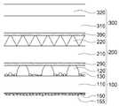
도 1은 본 발명의 확산판 기능포함 복합시트의 단면도이다.
도 2는 본 발명의 확산판 기능포함 복합시트의 다른 실시예에 대한 단면도이다.
도 3은 본 발명의 확산판 기능포함 복합시트의 또 다른 실시예에 대한 단면도이다.
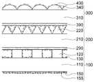
도 4는 제 4 확산무늬형이 추가적으로 더 포함된 확산판 기능포함 복합시트의 단면도이다.
도 5는 본 발명에서 스페이서 및 그와 접하는 구성요소들의 일 실시예에 대한 단면도이다.
도 6은 본 발명에서 제 1 프리즘 무늬형 및 그와 접하는 구성요소들의 일 실시예에 대한 단면도이다.
도 7은 본 발명에서 제 1 층의 일 실시예에 대한 사시도이다.
도 8은 본 발명에서 제 2 층의 일 실시예에 대한 사시도이다.1 is a cross-sectional view of a composite sheet including a diffusion plate function of the present invention.
2 is a cross-sectional view of another embodiment of a composite sheet including a diffuser plate function of the present invention.
3 is a cross-sectional view of another embodiment of a composite sheet including a diffusion plate function of the present invention.
4 is a cross-sectional view of a composite sheet including a diffusion plate function further including a fourth diffusion pattern.
5 is a cross-sectional view of one embodiment of the spacer and its adjacent components in the present invention.
FIG. 6 is a cross-sectional view of an embodiment of the first prism pattern and the adjacent components in the present invention.
7 is a perspective view of one embodiment of the first layer in the present invention.
8 is a perspective view of an embodiment of the second layer in the present invention.
이하, 본 발명의 바람직한 실시예에 대하여 상세히 설명한다. 또한, 하기의 설명에서는 구체적인 구성요소 등과 같은 많은 특정사항들이 설명되어 있는데, 이는 본 발명의 보다 전반적인 이해를 돕기 위해서 제공된 것일 뿐 이러한 특정 사항들 없이도 본 발명이 실시될 수 있음은 이 기술분야에서 통상의 지식을 가진 자에게는 자명하다 할 것이다. 그리고, 본 발명을 설명함에 있어서, 관련된 공지 기능 혹은 구성에 대한 구체적인 설명이 본 발명의 요지를 불필요하게 흐릴 수 있다고 판단되는 경우 그 상세한 설명을 생략한다.
Hereinafter, preferred embodiments of the present invention will be described in detail. In the following description, numerous specific details, such as specific elements, are set forth in order to provide a thorough understanding of the present invention, and it is to be understood that the present invention may be practiced without these specific details, It will be obvious to those who have knowledge of. In the following description of the present invention, a detailed description of known functions and configurations incorporated herein will be omitted when it may make the subject matter of the present invention rather unclear.
우선, 본 명세서에 사용된 용어 중 일부에 대해 정의한다.First, some of the terms used in this specification are defined.
본 명세서에서 수지란, 폴리머 뿐만 아니라 중합에 의하여 폴리머가 될 수 있는 모노머, 올리고머 또는 모노머 및 올리고머까지 포함하는 개념으로 사용하였다.As used herein, the term resin includes not only polymers but also monomers, oligomers or monomers and oligomers which can be polymers by polymerization.
본 명세서에서 프리즘 무늬형의 능선이란, 프리즘 무늬형 중 한 프리즘의 시작점의 꼭지각에서부터 끝점의 꼭지각을 따라 죽 이어진 선을 가리킨다.In the present specification, a prism-patterned ridgeline refers to a line that has been formed along the apex angle of the end point from the apex angle of the starting point of one of the prism patterns.
본 명세서에서 활성에너지선이란, 소정의 수지를 경화시킬 수 있는 정도의 에너지를 가진 입자선 및 전자기파를 함께 지칭하며, 자외선, 레이저, 마이크로웨이브, 전자선(electron beam), X-선 등을 포함한다.Herein, the active energy ray refers to a particle beam and an electromagnetic wave having an energy enough to cure a predetermined resin together, and includes ultraviolet rays, a laser, a microwave, an electron beam, an X-ray and the like .
본 명세서에서 활성에너지선경화형 수지란, 활성에너지선에 의해 경화될 수 있는 수지로서, 실제 무늬형(pattern)을 발현하는 층 또는 접착층의 소재가 되는 수지를 가리킨다.In the present specification, the active energy ray-curable resin refers to a resin which can be cured by an active energy ray, and which becomes a material for forming a layer or an adhesive layer that actually exhibits a pattern.
본 명세서 중 제 1 기재층(110)에서 스페이서(120)가 차지하는 면적이란, 제 1 기재층(110)과 맞닿아 있는 스페이서(120)의 밑부분 면적을 가리키는 것으로서, 단면이 사다리꼴인 스페이서(120)를 도시한 도 5에서 a를 한 변으로 하는 사각형의 면적이다.The area occupied by the
본 명세서에서 스페이서(120)가 제 2 접착층(290)과 접촉하는 접착면적이란, 제 2 접착층(290)에 함입되어 있는 스페이서(120) 정상부의 제 1 기재층(110)에 대한 정사영의 면적을 가리키는 것으로서, 단면이 사다리꼴인 스페이서(120)를 도시한 도 5에서 b를 한 변으로 하는 사각형의 면적이다.In this specification, the area of contact of the
본 명세서에서 프리즘 무늬형 중 한 프리즘의 밑면적이란, 기재층과 맞닿아 있는 한 프리즘의 밑면적, 즉, 상기 한 프리즘의 기재층에 대한 정사영의 면적을 가리키는 것으로서, 예컨대 제 1 프리즘 무늬형(220)을 도시한 도 6에서 c를 한 변으로 하는 사각형의 면적이다.The bottom surface area of one prism in the prism pattern shape refers to the bottom surface area of a prism that is in contact with the base layer, that is, the area of an orthorhombic surface with respect to the base layer of the prism, In Fig. 6 showing the area of a square having one side.
본 명세서에서 제 1 프리즘 무늬형(220) 중 한 프리즘이 제 3 접착층(390)과 접촉하는 접착면적이란, 제 3 접착층(390)에 함입되어 있는 한 프리즘 정상부의 제 2 기재층(210)에 대한 정사영의 면적을 가리키는 것으로서, 도 6에서 d를 한 변으로 하는 사각형의 면적이다.
In this specification, an area where one prism of the
이하, 도면을 참조하여 본 발명의 실시예에 대하여 상세히 설명한다.Hereinafter, embodiments of the present invention will be described in detail with reference to the drawings.
도 1은 본 발명의 확산판 기능포함 복합시트의 일 실시예에 대한 단면도이다. 더 상세히 설명하자면, 확산 기능을 하는 제 1 확산무늬형(150), 단면이 삼각형 모양의 스페이서(120) 및 반구 형태의 제 2 확산무늬형(130)을 포함하는 제 1 층(100)과, 제 1 프리즘 무늬형(220)이 일렬로 배열되어 있는 제 2 층(200), 및 반구 형태의 제 3 확산무늬형(330)을 포함하는 제 3 층(300)이 차례대로 쌓여 일체화되어 있는 확산판 기능포함 복합시트의 단면도이다.BRIEF DESCRIPTION OF THE DRAWINGS FIG. 1 is a cross-sectional view of an embodiment of a composite sheet including a diffusion plate function of the present invention. FIG. More specifically, the
도 2는 확산판 기능포함 복합시트의 다른 실시예에 대한 단면도이다. 더 상세히 설명하자면, 비드(155) 또는 필러(155)가 포함된 제 1 확산무늬형(150), 단면이 부분 원호 모양의 스페이서(120) 및 확산돌기 형태의 제 2 확산무늬형(130)을 포함하는 제 1 층(100)과, 제 1 프리즘 무늬형(220)이 일렬로 배열되어 있는 제 2 층(200), 및 제 2 프리즘 무늬형(320)을 포함하는 제 3 층(300)이 차례대로 쌓여 일체화되어 있는 확산판 기능포함 복합시트의 단면도이다.2 is a cross-sectional view of another embodiment of a composite sheet including a diffusion plate function. More specifically, a
도 3은 확산판 기능포함 복합시트의 또 다른 실시예에 대한 단면도이다. 더 상세히 설명하자면, 비드(155) 또는 필러(155)가 포함된 제 1 확산무늬형(150), 단면이 사각형 모양의 스페이서(120) 및 확산돌기 형태의 제 2 확산무늬형(130)을 포함하는 제 1 층(100)과, 제 1 프리즘 무늬형(220)이 일렬로 배열되어 있는 제 2 층(200), 및 렌즈 무늬형(340)을 포함하는 제 3 층(300)이 차례대로 쌓여 일체화되어 있는 확산판 기능포함 복합시트의 단면도이다.
3 is a cross-sectional view of another embodiment of a composite sheet including a diffusion plate function. More specifically, the
도 1 내지 도 3에 도시한 바와 같이 본 발명은,As shown in Figs. 1 to 3,
수지 재질의 제 1 기재층(110), 상기 제 1 기재층(110)의 하면에 비드(155) 또는 필러(155)가 포함되거나 포함되지 않은 수지를 포함하는 제 1 확산무늬형(150), 상기 제 1 기재층(110)의 상면에 서로 이격된 상태로 복수 개 형성된 기둥 형상의 스페이서(120), 및 상기 스페이서(120) 사이, 스페이서(120) 표면, 또는 스페이서(120) 사이 및 스페이서(120) 표면에 형성된 제 2 확산무늬형(130)을 포함하는 제 1 층(100)과,A
상기 제 1 층(100)의 스페이서(120) 정상부와 제 2 접착층(290)을 통해 접착된 수지 재질의 제 2 기재층(210), 및 상기 제 2 기재층(210)의 상면에 형성된 연속 배열된 제 1 프리즘 무늬형(220)을 포함하고, 상기 제 1 층(100)의 스페이서(120) 정상부의 수지와 상기 제 2 접착층(290)의 수지가 서로 중합반응하여 폴리머를 형성하는 제 2 층(200), 및A
상기 제 2 층(200)의 제 1 프리즘 무늬형(220)의 능선과 제 3 접착층(390)을 통해 접착된 수지 재질의 제 3 기재층(310)과 상기 제 3 기재층(310)의 상면에 형성된 제 2 프리즘 무늬형(320), 렌즈 무늬형(340), 제 3 확산무늬형(330) 및 그 조합으로 이루어진 군에서 선택되는 무늬형을 포함하고, 상기 제 2 층(200)의 제 1 프리즘 무늬형(220)의 수지와 상기 제 3 접착층(390)의 수지가 서로 중합반응하여 폴리머를 형성하는 제 3 층(300)을 포함하는, 확산판 기능포함 복합광학시트를 제공하는 것을 목적으로 한다.A
상기와 같이 본 발명의 확산판 기능포함 복합광학시트에서 서로 맞닿아 있는 각 층의 수지가 중합반응을 하여 폴리머를 형성하며 일체화되는 것은, 일체화되는 과정에서 본 발명 복합광학시트의 내구성과 강성을 더욱 높이는 데에 효과가 있다. 이처럼 인접한 각 층의 수지, 구체적으로 스페이서(120), 프리즘, 렌즈, 기타 확산무늬형을 완전경화시키기 전에 접착층과 중합반응시킴에 따라, 무늬형과 접착층을 일체로 경화시키고, 이로 인해 종래기술에 비해 얇은 접착층으로도 강한 결합력을 달성할 수 있다는 점이 본 발명의 주요한 특징이다. 이를 통해, 종래 스페이서(120)나 프리즘 무늬형 자체의 점착력만으로 인접한 층을 결합시킬 때 나타나는 상기 무늬형의 변형과 이로 인한 광학효율의 저하를 예방할 수 있다. 동시에, 종래 두꺼운 접착층으로 인접한 층을 결합시킴에 따라 상기 무늬형의 상당 부분이 접착층에 합입되어 나타나는 광학효율의 저하 역시 방지할 수 있다.As described above, in the composite optical sheet with a diffusing plate function of the present invention, the resin of each layer in contact with each other undergoes a polymerization reaction to form a polymer, which is integrated, It has an effect on height. By polymerizing the resin of each adjacent layer, specifically, the
또한, 상기 구성요소 중에서 프리즘 무늬형은 주로 집광 기능을 하며 확산무늬형은 주로 광의 확산 기능을 수행하며, 이에 제한되지는 않는다. 렌즈 무늬형(340)의 경우에는 광의 집광 및 확산 기능을 둘 다 수행할 수 있다.Among the above-mentioned components, the prism pattern type mainly functions as a condensing function, and the diffusion pattern type mainly performs a light diffusion function, but is not limited thereto. In the case of the
또한, 상기 본 발명의 확산판 기능포함 복합광학시트의 제 2 층(200)에 포함될 수 있는 제 1 프리즘 무늬형(220)과, 제 3 층(300)에 포함될 수 있는 제 3 확산무늬형(330), 제 2 프리즘 무늬형(320), 렌즈 무늬형(340) 및 그 조합으로 이루어진 군에서 선택되는 무늬형은 서로 수직으로 배열될 수 있으며, 이에 제한되지는 않는다. 수직 이외에도 다양한 각도로 배열될 수 있으며, 이로 인해 서로 간의 간섭이 조절되어 각 구성요소가 가지고 있는 기능이 효율적으로 구현될 수 있다.
The
또한, 도 4는 제 4 확산무늬형(430)이 추가적으로 더 포함된 확산판 기능포함 복합시트의 또 다른 실시예에 대한 단면도이다. 더 상세히 설명하자면, 도 3에서 나타낸 확산판 기능포함 복합시트에 제 4 확산무늬형(430)이 제 2 층(200)의 제 1 프리즘 무늬형(220) 표면, 제 2 접착층(290) 표면, 제 3 층(300)의 렌즈 무늬형(340) 표면 및 제 3 접착층(390) 표면에 확산돌기 형태의 제 4 확산무늬형(430)이 더 포함된 확산판 기능포함 복합시트의 단면도이다. 물론, 도 1에서처럼 제 1 층(100)에 반구 형태의 제 2 확산무늬형(130)이 형성되는 경우 상기 제 2 확산무늬형(130) 표면에도 제 4 확산무늬형(430)이 더 포함될 수 있다.
4 is a cross-sectional view of another embodiment of a composite sheet including a diffuser plate function further including a
도 4에 도시한 바와 같이 본 발명의 확산판 기능포함 복합광학시트는, 상기 제 1 층(100)의 제 1 확산무늬형(150) 표면, 제 2 층(200)의 제 1 프리즘 무늬형(220) 표면 및 제 2 접착층(290) 표면, 제 3 층(300)의 제 2 프리즘 무늬형(320), 렌즈 무늬형(340), 제 3 확산무늬형(330) 표면 및 제 3 접착층(390) 표면으로 이루어진 군에서 선택되는 한 면 또는 한 면 이상의 위치에 제 4 확산무늬형(430)을 더 포함할 수 있다. 각 층에 다양한 구성 요소가 존재하기 때문에, 제 4 확산무늬형(430)을 여러 위치에 선택적으로 포함시킴으로써 다른 구성 요소들과의 상호작용을 할 수 있다.4, the diffusive plate-equipped composite optical sheet of the present invention includes a
또한, 광이 복합광학시트 내의 각 층을 통과하며 집광, 확산, 또는 집광 및 확산 과정을 거칠 때 보조적인 역할을 하며 복합광학시트의 광 효율을 높일 수 있다. 한 예로 집광된 광이 확산될 때 균일하게 분산되도록 확산시켜줄 수 있다.
In addition, the light can pass through the respective layers in the composite optical sheet and function as an auxiliary when condensing, diffusing, or condensing and diffusing processes are performed, and the light efficiency of the composite optical sheet can be increased. As an example, when the condensed light is diffused, it can be diffused so as to be uniformly dispersed.
또한, 상기 제 1 확산무늬형(150), 스페이서(120), 제 2 확산무늬형(130), 제 2 접착층(290), 제 1 프리즘 무늬형(220), 제 3 접착층(390), 제 2 프리즘 무늬형(320), 렌즈 무늬형(340), 제 3 확산무늬형(330) 및 제 4 확산무늬형(430)은 열 경화형 또는 활성에너지선 경화형 수지를 주성분으로 포함한다. 또한, 상기 활성에너지선은 자외선일 수 있으며, 이에 제한되지는 않는다.
In addition, the
또한, 상기 제 1 기재층(110), 제 2 기재층(210) 및 제 3 기재층(310)의 수지는 폴리에틸렌테레프탈레이트 또는 폴리카보네이트일 수 있다. 폴리에틸렌테레프탈레이트 또는 폴리카보네이트는 광 투과성이 뛰어나 광원의 빛을 왜곡 없이 투과시킬 수 있으며, 내열성이 우수하여 열 변화에 대한 시트 손상을 최소화시킬 수 있다. 연성 또한 우수하여 기재층에 유연성을 부여할 수 있으며, 이로 인해 기재층에 추가적인 구성 요소를 더하는 과정에 있어서 좀 더 용이하게 기재층을 다룰 수 있다는 장점이 있다.
In addition, the resin of the
또한, 상기 제 1 확산무늬형(150)의 산술평균표면거칠기는 0.5 내지 3.5 ㎛, 바람직하게는 0.6 내지 3 ㎛, 보다 바람직하게는 0.8 내지 2.5 ㎛, 보다 더 바람직하게는 1 내지 2 ㎛ 인 것이 바람직하며, 이에 제한되지는 않는다. 이는 가공 시에 얼룩이나 뜯김이 발생하는 문제점을 방지하는 것과 동시에 기대한 만큼의 충분한 확산 효율을 얻을 수 있는 적절한 범위이다.
The arithmetic mean surface roughness of the
또한, 상기 스페이서(120)는 그 기둥 방향에 수직인 단면이 다각형, 반원형, 아치형, 부분 원호형 및 그 조합으로 이루어진 군에서 선택된 형태이다.In addition, the
도 7은 상기 스페이서(120)의 단면이 사다리꼴이고 제 2 확산무늬형(130)이 렌티큘러인 경우 제 1 층(100) 상면에 대한 사시도이다.7 is a perspective view of the upper surface of the
본 발명에서 기둥 형상의 스페이서(120)는 제 1 기재층(110)의 상면에 서로 이격된 상태로 복수 개 형성되어 있다. 제 1 층(100)과 제 2 층(200)은 스페이서(120)를 통해 맞닿아 있기 때문에 일체화에 필수적인 역할을 한다. 이때, 스페이서(120)의 기둥 방향에 수직인 단면의 형태에 따라 스페이서(120)가 제 2 접착층(290)과 접촉하는 접착면적의 비율이 달라질 수 있다.In the present invention, a plurality of
더불어, 제 1 층(100)의 제 1 기재층(110)과 제 2 층(200)의 제 2 접착층(290)이 스페이서(120)로 인해 일정 간격을 두고 떨어져 있기 때문에 두 층 간 공기층이 형성되어 있다. 공기의 굴절률은 1이고 공기 이외의 다른 물질의 굴절률은 1보다 크기 때문에, 각 층 간에 형성된 공기층은 광이 연직 방향으로 나아가는 데에 필수적인 역할을 한다. 공기 이외에 다른 물질이 채워져 있는 경우에는 복합광학시트의 집광 및 확산 효율이 떨어지게 된다. 따라서, 공기층을 통해 확산무늬형의 의도된 구조대로 광의 확산효과를 나타낼 수 있다.In addition, since the
또한, 스페이서(120)는 자체적으로도 그 단면 형태에 따라 확산 기능, 집광 기능 또는 확산과 집광 기능을 수행할 수 있다. 그리고 각각의 스페이서(120)가 이격된 상태로 형성되기 때문에 그 사이의 공간에 제 2 확산무늬형(130) 및 제 4 확산무늬형(430)이 형성될 수 있는 공간이 마련된다.
Also, the
한편, 상기 제 2 확산무늬형(130), 제 3 확산무늬형(330) 및 제 4 확산무늬형(430)은 평균 입경 1 내지 70 ㎛, 바람직하게는 2 내지 60 ㎛, 보다 바람직하게는 5 내지 50 ㎛, 보다 더 바람직하게는 10 내지 40 ㎛ 의 확산돌기, 평균 직경 10 내지 100 ㎛, 바람직하게는 15 내지 80 ㎛, 보다 바람직하게는 20 내지 70 ㎛, 보다 더 바람직하게는 30 내지 60 ㎛ 의 반구 및 그 조합으로 이루어진 군에서 선택될 수 있다. 확산돌기의 경우 광이 부분적으로 밀집되는 것을 방지하는 효과를 준다. 또한, 상기와 같은 평균 입경 범위를 가진 확산돌기를 이용함으로써, 디스플레이 화면에 Moire가 유발되는 것을 효과적으로 방지할 수 있고 충분한 광 확산효과를 얻을 수 있다. 그리고 반구 형태의 확산무늬형은 빛을 균일하게 확산시키는 효과를 준다. 또한, 상기와 같은 평균 직경 범위의 반구를 이용함으로써, 확산효율 및 휘도가 저하되는 것을 효과적으로 방지할 수 있다. 또한, 차폐 기능이 부족하지 않으면서 디스플레이 화면상 Moire가 발생되는 것을 방지할 수 있다.The
또한, 확산돌기는 단면의 형태가 다각형, 원형, 반원형, 아치형, 부분 원호형 및 그 조합으로 이루어진 군에서 선택될 수 있다. 다양한 단면 형태를 가짐으로써, 형태에 따른 입사각과 반사각의 차이에 따라 다 각도로 굴절과 반사를 일으켜 확산 효과를 줄 수 있다.Also, the diffusion protrusions may be selected from the group consisting of polygonal, circular, semicircular, arcuate, partial arcuate, and combinations thereof in cross-sectional shape. By having various cross-sectional shapes, refraction and reflection can occur at various angles depending on the difference between the incident angle and the reflection angle depending on the shape, thereby providing a diffusion effect.
반구의 경우에는, 벌집형(hexagonal) 또는 격자형(tetragonal)으로 배열될 수 있다. 벌집형 또는 격자형으로 배열하게 되면 랜덤하게 배열할 때보다 반구 형태의 확산무늬형을 더 조밀하게 배열시킬 수 있고, 따라서 확산효과를 더욱 강하게 그리고 골고루 발현시킬 수 있다. 또한, 요구 기능에 따라 배열 구조를 달리 함으로써 다른 광학 부재와의 간섭을 조절할 수 있다.
In the case of hemispheres, they may be arranged in hexagonal or tetragonal form. When arranged in a honeycomb or lattice pattern, the hemispherical pattern can be arranged more densely than when randomly arranged, and thus the diffusion effect can be more strongly and evenly expressed. Further, the interference with other optical members can be controlled by changing the arrangement structure according to the required function.
또한, 상기 제 1 기재층(110)에서 스페이서(120)가 차지하는 면적, 예컨대 도 5에서 a를 한 변으로 하는 사각형들 전체의 면적은 전체 제 1 기재층(110) 면적의 3 내지 50 %, 바람직하게는 4 내지 45 %, 보다 바람직하게는 5 내지 40 %, 보다 더 바람직하게는 5 내지 35 % 일 수 있으며, 이에 제한되지는 않는다. 이와 같은 범위의 면적으로 인해, 스페이서(120)가 위치한 제 1 층(100)에는 제 2 층(200)과 제 3 층(300)을 받쳐줄 수 있을 만한 충분한 힘이 부여된다. 또한, 제 1 기재층(110)과 제 2 접착층(290) 사이에 충분한 공기층이 확보될 수 있다. 또한, 제 1 층(100) 내의 제 2 확산무늬형(130), 제 4 확산무늬형(430) 또는 제 2 확산무늬형(130) 및 제 4 확산무늬형(430)이 충분하게 위치할 수 있게 된다.The area occupied by the
더불어, 제 1 기재층(110)의 면적에 대한 상기 스페이서(120)가 제 2 접착층(290)과 접촉하는 접착면적, 예컨대 도 5에서 b를 한 변으로 하는 사각형들 전체 면적의 비율은 3 내지 50 %, 바람직하게는 4 내지 45 %, 보다 바람직하게는 5 내지 40 %, 보다 더 바람직하게는 5 내지 35 % 일 수 있으며, 이에 제한되지는 않는다. 이와 같은 범위의 접착면적으로 인해, 스페이서(120)의 정상부의 수지와 중합반응을 이루는 제 2 접착층(290)의 면적이 충분하게 되어 제 1 층(100)과 제 2 층(200) 간의 결합력 내지 내구성이 떨어지는 것이 방지될 수 있다. 또한, 제 1 층(100)에서 확산무늬형이 충분한 확산 기능을 구현할 수 있을 만큼 위치할 수 있게 된다.5, the ratio of the total area of the squares having one side of b in Fig. 5 is preferably in the range of 3 to < RTI ID = 0.0 > But is not limited to, 50%, preferably 4 to 45%, more preferably 5 to 40%, and even more preferably 5 to 35%. Because of the adhesion area in this range, the area of the second
또한, 상기 기둥 형상의 스페이서(120)는 서로 평행하거나 평행하지 않을 수 있다. 배열을 다르게 함으로써 스페이서(120)가 제 2 기재층(210)의 제 2 접착층(290)과 접촉하는 길이와 면적을조절할 수 있다.In addition, the
더불어, 상기 기둥 형상의 스페이서(120)의 높이는 서로 같거나 상이할 수 있다. 높이가 상이할 경우 각 스페이서(120)는 다른 역할을 수행할 수 있다. 예를 들어 더 높은 높이의 스페이서(120)는 제 1 층(100)과 제 2 층(200)의 연결점 역할을 할 것이고, 더 낮은 높이의 스페이서(120)는 형태와 배열 구조에 따라 기존의 연결점 역할 이외에 확산이나 집광 등의 다른 역할도 수행할 수 있다.
In addition, the height of the
또한, 상기 제 1 프리즘 무늬형(220) 중 한 프리즘의 밑면적에 대한, 상기 한 프리즘이 제 3 접착층(390)과 접촉하는 접착면적, 예컨대 도 6에서 d를 한 변으로 하는 사각형 면적의 비율은 3 내지 15 %, 바람직하게는 4 내지 14 %, 보다 바람직하게는 5 내지 13 %, 보다 더 바람직하게는 6 내지 12 % 인 것이 바람직하며, 이에 제한되지는 않는다. 이로써, 제 1 프리즘 무늬형(220)의 정상부의 수지와 중합반응을 이루는 제 3 접착층(390)의 면적이 충분히 확보되어 제 2 층(200)과 제 3 층(300) 간의 결합력 내지 내구성이 떨어지는 것이 방지된다. 또한, 집광 기능이 이루어지는 프리즘의 두 면의 면적 손실이 심해지지 않아 충분한 집광 효율이 발현될 수 있다.In addition, the ratio of the area of adhesion of the prism to the third
또한, 본 발명의 제 1 프리즘 무늬형(220) 상단은 도 1에 도시된 바와 같이 제 3 기재층(310) 하면과 이격되어 중합 및 경화될 수도 있고, 도 6에 도시된 바와 같이 제 3 기재층(310) 하면과 접한 상태에서 중합 및 경화될 수도 있다. 이는 상기 스페이서(120)의 경우도 마찬가지여서, 도 5처럼 제 2 기재층(210) 하면과 접한 상태에서 중합 및 경화될 수도 있고, 하면에서 이격된 상태로 중합 및 경화될 수도 있다.1, the upper end of the
또한, 상기 연속 배열된 제 1 프리즘 무늬형(220) 및 제 2 프리즘 무늬형(320)은 서로 평행하거나 평행하지 않을 수 있으며, 제 1 프리즘 무늬형(220), 제 2 프리즘 무늬형(320), 제 2 확산무늬형(130), 제 3 확산무늬형(330), 렌즈 무늬형(340) 및 그 조합으로 이루어진 군에서 선택되는 무늬형의 높이는 서로 같거나 상이할 수 있다. 구체적으로, 예컨대 도 8의 A 방향에서 바라보았을 때 제 1 프리즘 무늬형(220)을 구성하는 각각의 프리즘 무늬형은 서로 평행할 수도 있고 서로 평행하지 않을 수도 있다. 그리고, 도 8의 B 방향에서 바라본 각 프리즘 무늬형의 높이 e는 서로 같을 수도 있고 서로 다를 수도 있다.
The
또한, 상기 제 2 기재층(210)이 이루는 면에 수직인 방향, 즉 도 8의 A 방향에서 바라보았을 때 상기 제 1 프리즘 무늬형(220)의 능선은 직선, 곡선, 또는 물결선일 수 있다.The ridgeline of the
또한, 본 발명의 확산판 기능포함 복합광학시트는 상기 제 3 기재층(310)이 이루는 면에 수직인 방향에서 상기 제 2 프리즘 무늬형(320)의 능선은 직선, 곡선, 또는 물결선일 수 있다.In the composite optical sheet with a diffusion plate function of the present invention, the ridgeline of the
또한, 상기 제 2 기재층(210)이 이루는 면에 평행하고 상기 제 1 프리즘 무늬형(220) 방향에 수직인 방향, 즉 도 8의 B 방향에서 바라보았을 때 상기 제 1 프리즘 무늬형(220)의 능선은 직선, 곡선, 또는 물결선일 수 있다.When the
또한, 상기 제 3 기재층(310)이 이루는 면에 평행하고 상기 제 2 프리즘 무늬형(320) 방향에 수직인 방향에서, 상기 제 2 프리즘 무늬형(320)의 능선은 직선, 곡선, 또는 물결선일 수 있다. 이와 같은 프리즘 무늬형 능선 형태의 변경은 Moire를 개선하는 데에 효과적이다.
The ridge line of the
또한, 상기 제 1 기재층(110) 하면의 비드(155)는 평균 입경 1 내지 15 ㎛, 바람직하게는 2 내지 14 ㎛, 보다 바람직하게는 3 내지 13 ㎛, 보다 더 바람직하게는 4 내지 12 ㎛ 인 투명입자일 수 있다. 이와 같은 범위의 비드(155)를 이용함으로써, 비드(155)의 내구성을 효과적으로 확보하고 확산기능을 수행하는 비드(155)의 충분한 확산 효율의 발현 또한 확보할 수 있다. 또한, 비드(155)가 포함되어 있는 제 1 확산무늬형(150)의 두께가 너무 두꺼워지는 문제점을 방지할 수 있다.The
또한, 상기 제 1 기재층(110) 하면의 필러(155)는 평균 입경 0.1 내지 3 ㎛, 바람직하게는 0.2 내지 2.5 ㎛, 보다 바람직하게는 0.3 내지 2 ㎛, 보다 더 바람직하게는 0.4 내지 1.5 ㎛ 인 무기입자일 수 있다. 이와 같은 범위의 필러(155)를 이용하는 것은, 필러(155)의 내구성을 확보하고 확산기능을 수행하는 필러(155)의 충분한 확산 효율이 발현되는 데에 효과적이다. 또한, 필러(155)가 포함되어 있는 제 1 확산무늬형(150)의 두께가 너무 두꺼워지는 문제점을 방지할 수 있다. 물론, 본 발명의 확산판 기능포함 복합광학시트를 구성하는 제 1 확산무늬형(150)은 도 1에 도시된 바와 같이 상기 비드(155)나 필러(155) 없이 확산기능을 발현하는 무늬형을 표면에 형성함으로써 보다 간편하고 경제적으로 제조하는 것도 가능하다.The
더불어, 상기 무기입자는 TiO2, SiO2, CaCO3및 그 조합으로 이루어진 군에서 선택될 수 있다. 특히 가장 많이 사용되는 TiO2무기입자의 경우, 은폐력이 크고 굴절률이 매우 큰 이방성을 나타내며 산란성도 크기 때문에 광의 확산 기능을 극대화시키는 데에 효과적이다. SiO2 무기입자의 경우에는 광에 대한 투과력이 뛰어나며 CaCO3 무기입자는 광 안정성이 뛰어나 더욱 안정적인 효율의 광을 구현할 수 있다는 이점이 있다.
In addition, the inorganic particles are TiO2, SiO2, CaCO3 And combinations thereof. In particular, TiO2 In the case of inorganic particles, it exhibits anisotropy with a large hiding power and a very high refractive index and is effective in maximizing the diffusion function of light because of its large scattering property. In the case of SiO2 inorganic particles, the transmittance to light is excellent, and CaCO3 inorganic particles are excellent in light stability, and thus, light of more stable efficiency can be realized.
이상에서는 본 발명의 바람직한 실시예에 대해서 설명하였으나, 본 발명은 상술한 특정의 실시예에 한정되지 아니하며, 당해 기술분야에서 통상의 지식을 가진 자라면 본원 발명의 요지를 벗어남이 없이 다양한 변형 실시가 가능함은 물론이다. 따라서, 본 발명의 범위는 위의 실시예에 국한해서 해석되어서는 안되며, 후술하는 특허청구범위 뿐만 아니라 이 특허청구범위와 균등한 것들에 의해 정해져야 할 것이다.
While the present invention has been described in connection with what is presently considered to be practical exemplary embodiments, it is to be understood that the invention is not limited to the disclosed embodiments, but, on the contrary, Of course it is possible. Accordingly, the scope of the present invention should not be construed as being limited to the above-described embodiments, but should be determined by equivalents to the appended claims, as well as the following claims.
150 : 제 1 확산무늬형155 : 비드 또는 필러
130 : 제 2 확산무늬형330 : 제 3 확산무늬형
430 : 제 4 확산무늬형100 : 제 1 층
110 : 제 1 기재층120 : 스페이서
200 : 제 2 층290 : 제 2 접착층
210 : 제 2 기재층220 : 제 1 프리즘 무늬형
300 : 제 3 층390 : 제 3 접착층
310 : 제 3 기재층320 : 제 2 프리즘 무늬형
340 : 렌즈 무늬형150: first diffusion pattern 155: bead or filler
130: second diffusion pattern 330: third diffusion pattern
430: fourth diffusion pattern 100: first layer
110: first base layer 120: spacer
200: second layer 290: second adhesive layer
210: second base layer 220: first prism patterned
300: third layer 390: third adhesive layer
310: third base layer 320: second prism pattern
340: Lens pattern type
Claims (19)
Translated fromKorean상기 제 1 기재층의 하면에 비드 또는 필러가 포함되거나 포함되지 않은 수지를 포함하는 제 1 확산무늬형,
상기 제 1 기재층의 상면에 서로 이격된 상태로 복수 개 형성된 기둥 형상의 스페이서, 및
상기 스페이서 사이, 상기 스페이서 표면, 또는 상기 스페이서 사이 및 상기 스페이서 표면에 형성된 제 2 확산무늬형을 포함하는 제 1 층;
상기 제 1 층의 스페이서 정상부와 제 2 접착층을 통해 접착된 수지 재질의 제 2 기재층, 및
상기 제 2 기재층의 상면에 형성된 연속 배열된 제 1 프리즘 무늬형을 포함하고,
상기 제 1 층의 스페이서 정상부의 수지 및 상기 제 2 접착층의 수지가 완전경화하기 전에 서로 접촉시켜 중합반응함으로써 폴리머를 형성하는 제 2 층; 및
상기 제 2 층의 제 1 프리즘 무늬형의 능선과 제 3 접착층을 통해 접착된 수지 재질의 제 3 기재층, 및
상기 제 3 기재층의 상면에 형성된 제 2 프리즘 무늬형, 렌즈 무늬형, 제 3 확산무늬형 및 그 조합으로 이루어진 군에서 선택되는 무늬형을 포함하고,
상기 제 2 층의 제 1 프리즘 무늬형의 수지 및 상기 제 3 접착층의 수지가 완전경화하기 전에 서로 접촉시켜 중합반응함으로써 폴리머를 형성하는 제 3 층을 포함하는, 확산판 기능포함 복합광학시트.
A first base layer made of a resin material,
A first diffusion pattern type resin including a resin containing or not containing a bead or a filler on a lower surface of the first base layer,
A plurality of columnar spacers formed on the upper surface of the first base layer so as to be spaced apart from each other,
A first layer comprising a second diffusion pattern formed between the spacers, on the spacer surface, or between the spacers and on the spacer surface;
A second base layer made of a resin material adhered via the second adhesive layer to the top of the spacer of the first layer,
And a first prism pattern formed continuously on the upper surface of the second base layer,
A second layer which forms a polymer by causing a resin at a top of the spacer of the first layer and a resin of the second adhesive layer to come into contact with each other before the resin is completely cured; And
A third base layer made of a resin material adhered via the first prism pattern ridge of the second layer and the third adhesive layer,
And a pattern type selected from the group consisting of a second prism pattern, a lens pattern, a third diffusion pattern, and a combination thereof formed on an upper surface of the third base layer,
And a third layer which forms a polymer by causing polymerization of the resin of the first prism pattern type resin of the second layer and the resin of the third adhesive layer before they are completely cured.
상기 제 1 층의 제 1 확산무늬형 표면, 제 2 층의 제 1 프리즘 무늬형 표면 또는 제 2 접착층 표면, 및 제 3 층의 제 2 프리즘 무늬형, 렌즈 무늬형, 제 3 확산무늬형 및 그 조합으로 이루어진 군에서 선택되는 무늬형 표면 또는 제 3 접착층 표면으로부터 선택되는 한 면 또는 한 면 이상의 위치에 제 4 확산무늬형을 더 포함하는 것을 특징으로 하는, 확산판 기능포함 복합광학시트.
The method according to claim 1,
A first prism pattern surface or a second adhesive layer surface of the first layer, a second prism pattern surface of the second layer, a second prism pattern surface of the second layer, a second prism pattern surface of the second layer, Wherein the fourth diffused pattern type further comprises a fourth diffused pattern at one or more faces selected from a patterned surface selected from the group consisting of a combination of the first diffuser plate and the third adhesive layer.
상기 제 1 확산무늬형, 스페이서, 제 2 확산무늬형, 제 2 접착층, 제 1 프리즘 무늬형, 제 3 접착층, 제 2 프리즘 무늬형, 렌즈 무늬형, 제 3 확산무늬형 및 제 4 확산무늬형은 열 경화형 또는 활성에너지선 경화형 수지를 포함하는 것을 특징으로 하는, 확산판 기능포함 복합광학시트.
3. The method of claim 2,
Wherein the first diffusion pattern, the spacer, the second diffusion pattern, the second adhesive layer, the first prism pattern, the third adhesive layer, the second prism pattern, the lens pattern, the third diffusion pattern, Characterized by comprising a thermosetting or active energy ray-curable resin.
상기 활성에너지선은 자외선인 것을 특징으로 하는, 확산판 기능포함 복합광학시트.
The method of claim 3,
Wherein the active energy ray is ultraviolet light.
상기 제 1 기재층, 제 2 기재층 및 제 3 기재층의 수지는 폴리에틸렌테레프탈레이트 또는 폴리카보네이트인 것을 특징으로 하는, 확산판 기능포함 복합광학시트.
The method according to claim 1,
Wherein the resin of the first base layer, the second base layer and the third base layer is polyethylene terephthalate or polycarbonate.
상기 제 1 확산무늬형의 산술평균표면거칠기는 0.5 내지 3.5 ㎛ 인 것을 특징으로 하는, 확산판 기능포함 복합광학시트.
The method according to claim 1,
And the arithmetic average surface roughness of the first diffusion pattern is 0.5 to 3.5 占 퐉.
상기 스페이서는 그 기둥 방향에 수직인 단면이 다각형, 반원형, 아치형, 부분 원호형 및 그 조합으로 이루어진 군에서 선택된 것을 특징으로 하는, 확산판 기능포함 복합광학시트.
The method according to claim 1,
Wherein the spacer is selected from the group consisting of a polygonal, semicircular, arcuate, semi-circular, and a combination of a cross section perpendicular to the column direction.
상기 제 2 확산무늬형, 제 3 확산무늬형 및 제 4 확산무늬형은 평균 입경 1 내지 70 ㎛ 의 확산돌기, 평균 직경 10 내지 100 ㎛ 의 반구 및 그 조합으로 이루어진 군에서 선택된 것을 특징으로 하는, 확산판 기능포함 복합광학시트.
3. The method of claim 2,
Wherein the second diffused pattern, the third diffused pattern and the fourth diffused pattern are selected from the group consisting of diffusion protrusions having an average particle diameter of 1 to 70 占 퐉, hemispheres having an average diameter of 10 to 100 占 퐉, and combinations thereof. Composite optical sheet with diffusion plate function.
상기 확산돌기는 단면의 형태가 다각형, 원형, 반원형, 아치형, 부분 원호형 및 그 조합으로 이루어진 군에서 선택된 것을 특징으로 하는, 확산판 기능포함 복합광학시트.
9. The method of claim 8,
Wherein the diffusion protrusions are selected from the group consisting of polygonal, circular, semicircular, arcuate, partial arcuate, and combinations thereof.
상기 반구는 벌집형(hexagonal) 또는 격자형(tetragonal)으로 배열된 것을 특징으로 하는, 확산판 기능포함 복합광학시트.
9. The method of claim 8,
Characterized in that the hemispheres are arranged in a hexagonal or tetragonal manner.
상기 제 1 기재층에서 스페이서가 차지하는 면적은 제 1 기재층 면적의 3 내지 50 % 인 것을 특징으로 하는, 확산판 기능포함 복합광학시트.
The method according to claim 1,
Wherein the area occupied by the spacer in the first base layer is 3 to 50% of the area of the first base layer.
상기 제 1 기재층의 면적에 대한, 상기 스페이서가 제 2 접착층과 접촉하는 접착면적의 비율은 3 내지 50 % 인 것을 특징으로 하는, 확산판 기능포함 복합광학시트.
The method according to claim 1,
Wherein the ratio of the area of adhesion of the spacer to the second adhesive layer to the area of the first base layer is 3 to 50%.
상기 제 1 프리즘 무늬형 중 한 프리즘의 밑면적에 대한, 상기 한 프리즘이 제 3 접착층과 접촉하는 접착면적의 비율은 3 내지 15 % 인 것을 특징으로 하는, 확산판 기능포함 복합광학시트.
The method according to claim 1,
Wherein the ratio of the area of bonding of the prism to the third adhesive layer to the bottom surface of one prism of the first prism pattern is 3 to 15%.
상기 제 1 프리즘 무늬형, 제 2 프리즘 무늬형, 제 2 확산무늬형, 제 3 확산무늬형, 렌즈 무늬형 및 그 조합으로 이루어진 군에서 선택되는 무늬형의 높이가 서로 같거나 상이한 것을 특징으로 하는, 확산판 기능포함 복합광학시트.
The method according to claim 1,
Wherein the heights of the pattern shapes selected from the group consisting of the first prism pattern shape, the second prism pattern shape, the second diffusion pattern shape, the third diffusion pattern shape, the lens pattern shape, and the combination thereof are equal to or different from each other , Compound optical sheet with diffuser plate function.
상기 제 2 기재층이 이루는 면에 수직인 방향에서 상기 제 1 프리즘 무늬형의 능선은 직선, 곡선, 또는 물결선이고, 상기 제 3 기재층이 이루는 면에 수직인 방향에서 상기 제 2 프리즘 무늬형의 능선은 직선, 곡선, 또는 물결선인 것을 특징으로 하는, 확산판 기능포함 복합광학시트.
The method according to claim 1,
Wherein the first prism pattern ridgeline is a straight line, a curved line, or a wavy line in a direction perpendicular to the plane formed by the second base layer, and the second prism patterned line in a direction perpendicular to the plane formed by the third base layer Is a straight line, a curved line, or a wavy line.
상기 제 2 기재층이 이루는 면에 평행하고 상기 제 1 프리즘 무늬형 방향에 수직인 방향에서 상기 제 1 프리즘 무늬형의 능선은 직선, 곡선, 또는 물결선이고, 상기 제 3 기재층이 이루는 면에 평행하고 상기 제 2 프리즘 무늬형 방향에 수직인 방향에서 상기 제 2 프리즘 무늬형의 능선은 직선, 곡선, 또는 물결선인 것을 특징으로 하는, 확산판 기능포함 복합광학시트.
The method according to claim 1,
The ridge line of the first prism pattern in a direction parallel to the plane formed by the second base layer and perpendicular to the first prism pattern direction is a straight line, a curved line, or a wavy line, Wherein the second prism pattern ridgeline is a straight line, a curved line, or a wavy line in a direction parallel to the first prism pattern direction and perpendicular to the second prism pattern direction.
상기 제 1 기재층 하면의 비드는 평균 입경 1 내지 15 ㎛ 인 투명입자인 것을 특징으로 하는, 확산판 기능포함 복합광학시트.
The method according to claim 1,
Wherein the beads on the lower surface of the first base layer are transparent particles having an average particle diameter of 1 to 15 占 퐉.
상기 제 1 기재층 하면의 필러는 평균 입경 0.1 내지 3 ㎛ 인 무기입자인 것을 특징으로 하는, 확산판 기능포함 복합광학시트.
The method according to claim 1,
Wherein the filler on the lower surface of the first base layer is an inorganic particle having an average particle diameter of 0.1 to 3 占 퐉.
상기 무기입자는 TiO2, SiO2, CaCO3 및 그 조합으로 이루어진 군에서 선택된 것을 특징으로 하는, 확산판 기능포함 복합광학시트.19. The method of claim 18,
Wherein the inorganic particles are selected from the group consisting of TiO2 , SiO2 , CaCO3, and combinations thereof.
Priority Applications (1)
| Application Number | Priority Date | Filing Date | Title |
|---|---|---|---|
| KR1020150172437AKR101767136B1 (en) | 2015-12-04 | 2015-12-04 | Composition optical sheet including function of diffusion plate integrated light diffusion means |
Applications Claiming Priority (1)
| Application Number | Priority Date | Filing Date | Title |
|---|---|---|---|
| KR1020150172437AKR101767136B1 (en) | 2015-12-04 | 2015-12-04 | Composition optical sheet including function of diffusion plate integrated light diffusion means |
Publications (2)
| Publication Number | Publication Date |
|---|---|
| KR20170065984A KR20170065984A (en) | 2017-06-14 |
| KR101767136B1true KR101767136B1 (en) | 2017-08-23 |
Family
ID=59218145
Family Applications (1)
| Application Number | Title | Priority Date | Filing Date |
|---|---|---|---|
| KR1020150172437AActiveKR101767136B1 (en) | 2015-12-04 | 2015-12-04 | Composition optical sheet including function of diffusion plate integrated light diffusion means |
Country Status (1)
| Country | Link |
|---|---|
| KR (1) | KR101767136B1 (en) |
Families Citing this family (3)
| Publication number | Priority date | Publication date | Assignee | Title |
|---|---|---|---|---|
| KR102413241B1 (en)* | 2017-06-23 | 2022-06-27 | 삼성디스플레이 주식회사 | Complex optical sheet and liquid crystal display device including the same |
| KR20200046225A (en) | 2018-10-23 | 2020-05-07 | 희성전자 주식회사 | Display device |
| CN115685422B (en)* | 2022-10-28 | 2025-09-23 | 马鞍山东毅新材料科技有限公司 | A microstructured composite diffusion membrane for mini and its production process |
Citations (2)
| Publication number | Priority date | Publication date | Assignee | Title |
|---|---|---|---|---|
| US20020048088A1 (en) | 1997-04-22 | 2002-04-25 | Dai Nippon Printing Co., Ltd. | Optical lamination sheet |
| JP2012230364A (en)* | 2011-04-12 | 2012-11-22 | Keiwa Inc | Light diffusion sheet, optical unit, backlight unit and liquid crystal display device |
- 2015
- 2015-12-04KRKR1020150172437Apatent/KR101767136B1/enactiveActive
Patent Citations (2)
| Publication number | Priority date | Publication date | Assignee | Title |
|---|---|---|---|---|
| US20020048088A1 (en) | 1997-04-22 | 2002-04-25 | Dai Nippon Printing Co., Ltd. | Optical lamination sheet |
| JP2012230364A (en)* | 2011-04-12 | 2012-11-22 | Keiwa Inc | Light diffusion sheet, optical unit, backlight unit and liquid crystal display device |
Also Published As
| Publication number | Publication date |
|---|---|
| KR20170065984A (en) | 2017-06-14 |
Similar Documents
| Publication | Publication Date | Title |
|---|---|---|
| JP5018371B2 (en) | Optical sheet, backlight unit and display device | |
| KR101822706B1 (en) | Optical sheet and optical display apparatus comprising the same | |
| KR100957496B1 (en) | Reflective polarizing film, backlight unit and liquid crystal display including the same | |
| JP5595906B2 (en) | Optical element, and backlight unit and liquid crystal display including the same | |
| KR101178722B1 (en) | Light guide panel and lcd back light unit using the same | |
| KR101629887B1 (en) | Optical sheet and back light unit including the same | |
| KR101052799B1 (en) | Optical sheet, backlight unit and liquid crystal display including the same | |
| KR20070108794A (en) | Back light assembly of the liquid crystal display device provided with the optical sheet and the optical sheet | |
| TW201604602A (en) | Light guide plate, method for fabricating the same, backlight unit, and liquid crystal display | |
| KR20140047412A (en) | Tandem array lens sheet | |
| KR20100095765A (en) | Optical sheet | |
| KR101767136B1 (en) | Composition optical sheet including function of diffusion plate integrated light diffusion means | |
| JP5003298B2 (en) | Optical sheet, backlight unit using the same, and display device | |
| KR101767137B1 (en) | Composition optical sheet including function of diffusion plate integrated light diffusion means | |
| KR101534341B1 (en) | An optical sheet including a high- | |
| JP5012221B2 (en) | Backlight unit and display device | |
| KR102539878B1 (en) | Optical sheet and method for fabricating the optical sheet | |
| JP5509532B2 (en) | Optical member, backlight unit, and display device | |
| JP2012215895A (en) | Backlight unit and display device | |
| KR20150015319A (en) | Complex optical sheet and back light unit comprising the same | |
| KR101209803B1 (en) | Method for manufacturing one body type optical film and one body type optical film | |
| JP2011145476A (en) | Optical sheet, surface light source device, and transmission type display device | |
| JP2009069347A (en) | Optical sheet and backlight unit using the same | |
| KR20150034553A (en) | Complex optical sheet and liquid crystal display comprising the same | |
| KR20140014736A (en) | Optical sheet and display apparatus comprising the same |
Legal Events
| Date | Code | Title | Description |
|---|---|---|---|
| A201 | Request for examination | ||
| PA0109 | Patent application | St.27 status event code:A-0-1-A10-A12-nap-PA0109 | |
| PA0201 | Request for examination | St.27 status event code:A-1-2-D10-D11-exm-PA0201 | |
| R18-X000 | Changes to party contact information recorded | St.27 status event code:A-3-3-R10-R18-oth-X000 | |
| D13-X000 | Search requested | St.27 status event code:A-1-2-D10-D13-srh-X000 | |
| D14-X000 | Search report completed | St.27 status event code:A-1-2-D10-D14-srh-X000 | |
| E902 | Notification of reason for refusal | ||
| PE0902 | Notice of grounds for rejection | St.27 status event code:A-1-2-D10-D21-exm-PE0902 | |
| T11-X000 | Administrative time limit extension requested | St.27 status event code:U-3-3-T10-T11-oth-X000 | |
| T11-X000 | Administrative time limit extension requested | St.27 status event code:U-3-3-T10-T11-oth-X000 | |
| T11-X000 | Administrative time limit extension requested | St.27 status event code:U-3-3-T10-T11-oth-X000 | |
| T11-X000 | Administrative time limit extension requested | St.27 status event code:U-3-3-T10-T11-oth-X000 | |
| P11-X000 | Amendment of application requested | St.27 status event code:A-2-2-P10-P11-nap-X000 | |
| P13-X000 | Application amended | St.27 status event code:A-2-2-P10-P13-nap-X000 | |
| PG1501 | Laying open of application | St.27 status event code:A-1-1-Q10-Q12-nap-PG1501 | |
| E701 | Decision to grant or registration of patent right | ||
| PE0701 | Decision of registration | St.27 status event code:A-1-2-D10-D22-exm-PE0701 | |
| GRNT | Written decision to grant | ||
| PR0701 | Registration of establishment | St.27 status event code:A-2-4-F10-F11-exm-PR0701 | |
| PR1002 | Payment of registration fee | St.27 status event code:A-2-2-U10-U11-oth-PR1002 Fee payment year number:1 | |
| PG1601 | Publication of registration | St.27 status event code:A-4-4-Q10-Q13-nap-PG1601 | |
| P22-X000 | Classification modified | St.27 status event code:A-4-4-P10-P22-nap-X000 | |
| PR1001 | Payment of annual fee | St.27 status event code:A-4-4-U10-U11-oth-PR1001 Fee payment year number:4 | |
| P14-X000 | Amendment of ip right document requested | St.27 status event code:A-5-5-P10-P14-nap-X000 | |
| PR1001 | Payment of annual fee | St.27 status event code:A-4-4-U10-U11-oth-PR1001 Fee payment year number:5 | |
| S20-X000 | Security interest recorded | St.27 status event code:A-4-4-S10-S20-lic-X000 | |
| PR1001 | Payment of annual fee | St.27 status event code:A-4-4-U10-U11-oth-PR1001 Fee payment year number:6 | |
| PR1001 | Payment of annual fee | St.27 status event code:A-4-4-U10-U11-oth-PR1001 Fee payment year number:7 | |
| S20-X000 | Security interest recorded | St.27 status event code:A-4-4-S10-S20-lic-X000 | |
| PR1001 | Payment of annual fee | St.27 status event code:A-4-4-U10-U11-oth-PR1001 Fee payment year number:8 | |
| PR1001 | Payment of annual fee | St.27 status event code:A-4-4-U10-U11-oth-PR1001 Fee payment year number:9 |