KR101767063B1 - Hermetic compressor - Google Patents
Hermetic compressorDownload PDFInfo
- Publication number
- KR101767063B1 KR101767063B1KR1020100138169AKR20100138169AKR101767063B1KR 101767063 B1KR101767063 B1KR 101767063B1KR 1020100138169 AKR1020100138169 AKR 1020100138169AKR 20100138169 AKR20100138169 AKR 20100138169AKR 101767063 B1KR101767063 B1KR 101767063B1
- Authority
- KR
- South Korea
- Prior art keywords
- shell
- accumulator
- cylinder
- space
- vane
- Prior art date
- Legal status (The legal status is an assumption and is not a legal conclusion. Google has not performed a legal analysis and makes no representation as to the accuracy of the status listed.)
- Expired - Fee Related
Links
Images


Classifications
- F—MECHANICAL ENGINEERING; LIGHTING; HEATING; WEAPONS; BLASTING
- F04—POSITIVE - DISPLACEMENT MACHINES FOR LIQUIDS; PUMPS FOR LIQUIDS OR ELASTIC FLUIDS
- F04C—ROTARY-PISTON, OR OSCILLATING-PISTON, POSITIVE-DISPLACEMENT MACHINES FOR LIQUIDS; ROTARY-PISTON, OR OSCILLATING-PISTON, POSITIVE-DISPLACEMENT PUMPS
- F04C23/00—Combinations of two or more pumps, each being of rotary-piston or oscillating-piston type, specially adapted for elastic fluids; Pumping installations specially adapted for elastic fluids; Multi-stage pumps specially adapted for elastic fluids
- F04C23/008—Hermetic pumps
- F—MECHANICAL ENGINEERING; LIGHTING; HEATING; WEAPONS; BLASTING
- F04—POSITIVE - DISPLACEMENT MACHINES FOR LIQUIDS; PUMPS FOR LIQUIDS OR ELASTIC FLUIDS
- F04C—ROTARY-PISTON, OR OSCILLATING-PISTON, POSITIVE-DISPLACEMENT MACHINES FOR LIQUIDS; ROTARY-PISTON, OR OSCILLATING-PISTON, POSITIVE-DISPLACEMENT PUMPS
- F04C18/00—Rotary-piston pumps specially adapted for elastic fluids
- F04C18/30—Rotary-piston pumps specially adapted for elastic fluids having the characteristics covered by two or more of groups F04C18/02, F04C18/08, F04C18/22, F04C18/24, F04C18/48, or having the characteristics covered by one of these groups together with some other type of movement between co-operating members
- F04C18/32—Rotary-piston pumps specially adapted for elastic fluids having the characteristics covered by two or more of groups F04C18/02, F04C18/08, F04C18/22, F04C18/24, F04C18/48, or having the characteristics covered by one of these groups together with some other type of movement between co-operating members having both the movement defined in group F04C18/02 and relative reciprocation between the co-operating members
- F04C18/322—Rotary-piston pumps specially adapted for elastic fluids having the characteristics covered by two or more of groups F04C18/02, F04C18/08, F04C18/22, F04C18/24, F04C18/48, or having the characteristics covered by one of these groups together with some other type of movement between co-operating members having both the movement defined in group F04C18/02 and relative reciprocation between the co-operating members with vanes hinged to the outer member and reciprocating with respect to the outer member
- F—MECHANICAL ENGINEERING; LIGHTING; HEATING; WEAPONS; BLASTING
- F04—POSITIVE - DISPLACEMENT MACHINES FOR LIQUIDS; PUMPS FOR LIQUIDS OR ELASTIC FLUIDS
- F04C—ROTARY-PISTON, OR OSCILLATING-PISTON, POSITIVE-DISPLACEMENT MACHINES FOR LIQUIDS; ROTARY-PISTON, OR OSCILLATING-PISTON, POSITIVE-DISPLACEMENT PUMPS
- F04C29/00—Component parts, details or accessories of pumps or pumping installations, not provided for in groups F04C18/00 - F04C28/00
- F04C29/0021—Systems for the equilibration of forces acting on the pump
- F04C29/0035—Equalization of pressure pulses
- F—MECHANICAL ENGINEERING; LIGHTING; HEATING; WEAPONS; BLASTING
- F04—POSITIVE - DISPLACEMENT MACHINES FOR LIQUIDS; PUMPS FOR LIQUIDS OR ELASTIC FLUIDS
- F04C—ROTARY-PISTON, OR OSCILLATING-PISTON, POSITIVE-DISPLACEMENT MACHINES FOR LIQUIDS; ROTARY-PISTON, OR OSCILLATING-PISTON, POSITIVE-DISPLACEMENT PUMPS
- F04C2240/00—Components
- F04C2240/40—Electric motor
- F—MECHANICAL ENGINEERING; LIGHTING; HEATING; WEAPONS; BLASTING
- F04—POSITIVE - DISPLACEMENT MACHINES FOR LIQUIDS; PUMPS FOR LIQUIDS OR ELASTIC FLUIDS
- F04C—ROTARY-PISTON, OR OSCILLATING-PISTON, POSITIVE-DISPLACEMENT MACHINES FOR LIQUIDS; ROTARY-PISTON, OR OSCILLATING-PISTON, POSITIVE-DISPLACEMENT PUMPS
- F04C2240/00—Components
- F04C2240/80—Other components
- F04C2240/804—Accumulators for refrigerant circuits
- F—MECHANICAL ENGINEERING; LIGHTING; HEATING; WEAPONS; BLASTING
- F04—POSITIVE - DISPLACEMENT MACHINES FOR LIQUIDS; PUMPS FOR LIQUIDS OR ELASTIC FLUIDS
- F04C—ROTARY-PISTON, OR OSCILLATING-PISTON, POSITIVE-DISPLACEMENT MACHINES FOR LIQUIDS; ROTARY-PISTON, OR OSCILLATING-PISTON, POSITIVE-DISPLACEMENT PUMPS
- F04C2270/00—Control; Monitoring or safety arrangements
- F04C2270/12—Vibration
- F—MECHANICAL ENGINEERING; LIGHTING; HEATING; WEAPONS; BLASTING
- F04—POSITIVE - DISPLACEMENT MACHINES FOR LIQUIDS; PUMPS FOR LIQUIDS OR ELASTIC FLUIDS
- F04C—ROTARY-PISTON, OR OSCILLATING-PISTON, POSITIVE-DISPLACEMENT MACHINES FOR LIQUIDS; ROTARY-PISTON, OR OSCILLATING-PISTON, POSITIVE-DISPLACEMENT PUMPS
- F04C29/00—Component parts, details or accessories of pumps or pumping installations, not provided for in groups F04C18/00 - F04C28/00
- F04C29/02—Lubrication; Lubricant separation
- F04C29/025—Lubrication; Lubricant separation using a lubricant pump
- F—MECHANICAL ENGINEERING; LIGHTING; HEATING; WEAPONS; BLASTING
- F04—POSITIVE - DISPLACEMENT MACHINES FOR LIQUIDS; PUMPS FOR LIQUIDS OR ELASTIC FLUIDS
- F04C—ROTARY-PISTON, OR OSCILLATING-PISTON, POSITIVE-DISPLACEMENT MACHINES FOR LIQUIDS; ROTARY-PISTON, OR OSCILLATING-PISTON, POSITIVE-DISPLACEMENT PUMPS
- F04C29/00—Component parts, details or accessories of pumps or pumping installations, not provided for in groups F04C18/00 - F04C28/00
- F04C29/06—Silencing
Landscapes
- Engineering & Computer Science (AREA)
- Mechanical Engineering (AREA)
- General Engineering & Computer Science (AREA)
- Applications Or Details Of Rotary Compressors (AREA)
- Compressor (AREA)
Abstract
Translated fromKoreanDescription
Translated fromKorean본 발명은 밀폐형 압축기에 관한 것으로, 특히 어큐뮬레이터를 압축기 쉘과 모듈화할 수 있는 밀폐형 압축기에 관한 것이다.The present invention relates to a hermetic compressor, and more particularly to a hermetic compressor capable of modulating an accumulator with a compressor shell.
일반적으로 밀폐형 압축기는 밀폐된 쉘(shell)의 내부공간에 구동력을 발생하는 구동모터와 그 구동모터에 결합되어 작동하면서 냉매를 압축하는 압축유닛이 함께 설치되어 있다. 그리고 상기 밀폐형 압축기는 냉매를 압축하는 방식에 따라 왕복동식, 스크롤식, 로터리식, 진동식 등으로 구분할 수 있다. 상기 왕복동식과 스크롤식 그리고 로터리식은 구동모터의 회전력을 이용하는 방식이고, 상기 진동식은 구동모터의 왕복운동을 이용하는 방식이다.Generally, a hermetic compressor is provided with a driving motor for generating a driving force in an internal space of a sealed shell, and a compression unit for being coupled to the driving motor to compress the refrigerant. The hermetic compressor may be divided into a reciprocating type, a scroll type, a rotary type, and an oscillating type depending on a method of compressing a refrigerant. The reciprocating type, the scroll type, and the rotary type are methods using the rotational force of the driving motor, and the oscillating type is a method using the reciprocating motion of the driving motor.
상기와 같은 밀폐형 압축기 중에서 회전력을 이용하는 밀폐형 압축기의 구동모터에는 크랭크축이 구비되어 그 구동모터의 회전력을 압축유닛에 전달하도록 구성되어 있다. 예컨대, 상기 로터리식 밀폐형 압축기(이하, 로터리 압축기)의 구동모터는 상기 쉘에 고정되는 고정자와, 상기 고정자에 일정 공극을 두고 삽입되어 상기 고정자와의 상호작용으로 회전하는 회전자와, 상기 회전자에 결합되어 함께 회전을 하면서 상기 구동모터의 회전력을 상기 압축유닛에 전달하는 크랭크축으로 이루어져 있다. 그리고 상기 압축유닛은 압축공간을 형성하는 실린더와, 그 실린더의 압축공간을 흡입실과 토출실으로 분리하는 베인과, 상기 베인을 지지하는 동시에 상기 실리더와 함께 압축공간을 형성하는 복수 개의 베어링부재로 이루어져 있다. 상기 베어링부재는 상기 구동모터의 일측에 배치되거나 또는 양측에 각각 배치되어 상기 크랭크축이 실린더에 대해 회전할 수 있도록 축방향과 반경방향으로 지지하고 있다.Among the hermetic compressors described above, the drive motor of the hermetic compressor utilizing the rotational force is provided with a crankshaft so that the rotational force of the drive motor is transmitted to the compression unit. For example, the driving motor of the rotary hermetic compressor (hereafter referred to as a rotary compressor) includes a stator fixed to the shell, a rotor inserted in the stator with a predetermined gap therebetween and rotated by interaction with the stator, And a crankshaft coupled to the crankshaft and rotating together to transmit the rotational force of the driving motor to the compression unit. The compression unit includes a cylinder defining a compression space, a vane separating a compression space of the cylinder into a suction chamber and a discharge chamber, and a plurality of bearing members supporting the vane and forming a compression space together with the cylinder consist of. The bearing member is disposed on one side of the driving motor or on both sides thereof, and is supported axially and radially so that the crankshaft can rotate relative to the cylinder.
그리고 상기 쉘의 일측에는 상기 실린더의 흡입구에 연결되어 그 흡입구로 흡입되는 냉매를 가스냉매와 액냉매로 분리하여 가스냉매만 압축공간으로 흡입되도록 하는 어큐뮬레이터가 설치되어 있다.An accumulator is installed at one side of the shell to separate the refrigerant, which is connected to the suction port of the cylinder and is sucked into the suction port, into a gas refrigerant and a liquid refrigerant so that only the gas refrigerant is sucked into the compression space.
상기 어큐뮬레이터는 압축기의 용량 또는 냉동시스템의 용량에 따라 그 용량이 결정되어 상기 쉘의 외부에서 밴드 또는 클램프 등으로 고정되고 엘(L)자 모양의 흡입관으로 상기 실린더의 흡입구에 연통되어 쉘에 고정되어 있다.The capacity of the accumulator is determined according to the capacity of the compressor or the capacity of the refrigeration system. The accumulator is fixed to the outside of the shell with a band or a clamp, and is connected to the inlet of the cylinder through an L- have.
그러나, 상기와 같은 종래의 로터리 압축기의 경우에는, 상기 어큐뮬레이터가 쉘의 외부에 설치됨에 따라 상기 어큐뮬레이터를 포함한 압축기의 크기가 커지고 이로 인해 압축기를 채용하는 전기제품의 크기가 커지게 되는 문제점이 있었다.However, in the conventional rotary compressor as described above, since the accumulator is installed outside the shell, the size of the compressor including the accumulator becomes large, which increases the size of the electric appliance adopting the compressor.
또, 종래의 로터리 압축기는, 상기 어큐뮬레이터가 쉘의 외곽에서 별도의 흡입관으로 연결됨에 따라 상기 쉘의 조립과 어큐뮬레이터의 조립이 분리되어 압축기의 조립공수가 증가하면서 조립공정이 복잡하게 되는 것은 물론, 상기 어큐뮬레이터의 양측을 냉매관으로 쉘에 연결함에 따라 연결부위가 증가하여 냉매가 누설될 가능성이 증가하는 문제점도 있었다.In the conventional rotary compressor, since the accumulator is connected to the suction pipe at the outer periphery of the shell, the assembly of the shell and the assembly of the accumulator are separated from each other, so that the assembling process of the compressor is complicated, There is a problem that the possibility of leakage of the refrigerant increases due to an increase in the number of connection portions.
또, 종래의 로터리 압축기는, 상기 어큐뮬레이터가 상기 쉘의 외곽에 설치됨에 따라 상기 압축기가 차지하는 면적이 증가하게 되고, 이로 인해 상기 압축기를 냉동사이클장치의 실외기 등에 장착하는 경우 실외기의 설계 자유도를 제한하는 문제점도 있었다.In addition, in the conventional rotary compressor, the area occupied by the compressor increases as the accumulator is installed on the outer side of the shell, thereby limiting the degree of freedom of design of the outdoor unit when the compressor is mounted to the outdoor unit of the refrigeration cycle apparatus There was also a problem.
또, 종래의 로터리 압축기는, 상기 어큐뮬레이터가 그 어큐뮬레이터를 포함한 전체 압축기의 무게중심에 대해 편심되어 상기 쉘의 외곽에 설치됨에 따라 상기 어큐뮬레이터로 인한 편심하중이 발생되고 이로 인해 압축기의 진동 소음이 커지는 문제점도 있었다.Also, in the conventional rotary compressor, since the accumulator is eccentrically arranged with respect to the center of gravity of the entire compressor including the accumulator, and is installed at the outer side of the shell, an eccentric load due to the accumulator is generated and vibration noise of the compressor is increased .
또, 종래의 로터리 압축기는, 상기 크랭크축이 회전을 함에 따라 편심부의 편심량이 너무 큰 경우에는 상기 크랭크축의 편심하중이 증가하면서 압축기 진동이 가중될 수 있고 반대로 편심부의 편심량이 작은 경우에는 압축기 용량이 작아지는 문제점도 있었다.In the conventional rotary compressor, when the eccentric amount of the eccentric portion is too large as the crankshaft rotates, the eccentric load of the crankshaft increases, and the vibration of the compressor can be increased. On the contrary, There was also a problem of becoming small.
또, 종래의 로터리 압축기는, 상기 크랭크축의 편심부에 롤링피스톤이 회전 가능하게 결합되고 그 롤링피스톤에 상기 베인이 접촉하여 압축공간을 형성하는 것이나, 운전 중에 상기 베인이 롤링피스톤으로부터 분리되면서 상기 롤링피스톤과 베인 사이에 틈새가 발생되어 압축기의 압축손실이 야기되는 문제점도 있었다.In the conventional rotary compressor, a rolling piston is rotatably coupled to the eccentric portion of the crankshaft and the vane is in contact with the rolling piston to form a compression space. During operation, the vane is separated from the rolling piston, There is a problem that a gap is generated between the piston and the vane, causing compression loss of the compressor.
본 발명의 목적은, 상기 쉘의 내부공간을 이용하여 어큐뮬레이터의 어큠공간을 구성함으로써 상기 어큐뮬레이터를 포함한 압축기의 크기를 줄이고 이를 통해 압축기를 채용하는 전기제품의 크기를 줄일 수 있는 밀폐형 압축기를 제공하려는데 있다.It is an object of the present invention to provide a hermetic compressor which can reduce the size of the compressor including the accumulator and reduce the size of the electric appliance employing the compressor by configuring a space of the accumulator using the internal space of the shell .
본 발명의 다른 목적은, 상기 어큐뮬레이터의 조립공정과 쉘의 조립공정을 일원화하여 압축기의 조립공정을 간소화하는 동시에 상기 어큐뮬레이터의 조립시 연결부위를 줄여 냉매누설을 미연에 방지할 수 있는 밀폐형 압축기를 제공하려는데 있다.It is another object of the present invention to provide a hermetic compressor capable of simplifying the assembling process of the compressor by unifying the assembling process of the accumulator and the assembling process of the shell and at the same time reducing the connecting portion when assembling the accumulator, I'm trying to.
본 발명의 다른 목적은, 어큐뮬레이터를 포함한 압축기를 실외기에 설치할 때 그 압축기의 설치에 필요한 면적을 최소화하여 실외기의 설계 자유도를 높일 수 있는 밀폐형 압축기를 제공하려는데 있다.Another object of the present invention is to provide a hermetic compressor capable of increasing the degree of freedom of design of an outdoor unit by minimizing an area required for installation of the compressor including the accumulator in the outdoor unit.
본 발명의 다른 목적은, 상기 어큐뮬레이터의 무게중심이 그 어큐뮬레이터를 포함한 전체 압축기의 무게중심과 일치하는 위치에 설치되도록 하여 상기 어큐뮬레이터로 인한 압축기의 진동 소음을 감쇄시킬 수 있는 밀폐형 압축기를 제공하려는데 있다.Another object of the present invention is to provide a hermetic compressor in which the center of gravity of the accumulator is installed at a position coinciding with the center of gravity of the entire compressor including the accumulator to attenuate the vibration noise of the compressor due to the accumulator.
본 발명의 다른 목적은, 축에 편심부를 형성하면서도 압축기의 진동을 줄일 수 있고 상기 편심부의 편심량을 크게 하여 압축기 용량을 증가시킬 수 있는 밀폐형 압축기를 제공하려는데 있다.It is another object of the present invention to provide a hermetic compressor capable of reducing the vibration of the compressor while increasing the amount of eccentricity of the compressor while increasing the capacity of the compressor while forming an eccentric portion on the shaft.
본 발명의 다른 목적은, 상기 롤링피스톤과 베인 사이에서의 냉매누설이 발생되는 것을 미연에 방지할 수 있는 밀폐형 압축기를 제공하려는데 있다.Another object of the present invention is to provide a hermetic compressor capable of preventing refrigerant leakage from occurring between the rolling piston and the vane.
본 발명의 목적을 달성하기 위하여, 밀폐된 내부공간을 갖는 쉘; 상기 쉘의 내부공간에 고정 설치되는 고정자; 상기 고정자에 대해 회전 가능하게 구비되어 회전을 하는 회전자; 상기 회전자에 결합되어 함께 회전을 하는 실린더; 상기 실린더의 상하 양측을 복개하여 그 실린더와 함께 압축공간을 형성하고 상기 실린더에 결합되어 함께 회전을 하는 복수 개의 베어링 플레이트; 상기 쉘의 내부공간에서 고정되고, 상기 실린더의 회전중심과 일치하도록 축중심이 형성되며, 상기 베어링 플레이트를 축방향으로 지지하는 동시에 상기 실린더의 회전시 압축공간의 체적이 가변되도록 하는 편심부가 형성되고, 상기 압축공간으로 냉매를 안내하도록 냉매흡입유로가 형성되는 고정축; 상기 실린더와 함께 회전을 하면서 상기 편심부에 대해 미끄러지도록 상기 실린더에 결합되어 상기 압축공간을 흡입실과 토출실로 분리하면서 냉매가 압축되도록 하는 롤링베인; 및 상기 쉘의 내부공간과 분리되는 소정의 어큠공간을 가지며 그 어큠공간에 흡입관이 연통되는 어큐뮬레이터;를 포함하고, 상기 어큐뮬레이터에는 상기 고정축의 일단이 삽입 결합되어 그 고정축의 냉매흡입유로가 상기 어큠공간에 연통되는 밀폐형 압축기가 제공된다.In order to accomplish the object of the present invention, a shell having a sealed inner space; A stator fixedly installed in an inner space of the shell; A rotor rotatably mounted on the stator; A cylinder coupled to the rotor and rotating together; A plurality of bearing plates that cover both upper and lower sides of the cylinder to form a compression space together with the cylinder and are coupled to the cylinder and rotate together; An eccentric portion is formed in the inner space of the shell and is axially centered so as to coincide with the center of rotation of the cylinder, and an eccentric portion for supporting the bearing plate in the axial direction and varying the volume of the compression space when the cylinder is rotated A fixed shaft having a refrigerant suction path for guiding the refrigerant into the compression space; A rolling vane coupled to the cylinder so as to be slid with respect to the eccentric portion while rotating together with the cylinder to separate the compression space into a suction chamber and a discharge chamber to compress the refrigerant; And an accumulator having a predetermined space separated from the inner space of the shell and connected to the suction space, wherein one end of the fixed shaft is inserted into the accumulator, and the refrigerant suction channel of the fixed shaft is connected to the outer space Is provided.
본 발명에 의한 밀폐형 압축기는, 상기 어큐뮬레이터가 쉘의 내부공간에 설치됨에 따라 쉘의 내부공간을 활용할 수 있고 이를 통해 어큐뮬레이터를 포함하는 압축기의 크기를 줄일 수 있다.In the hermetic compressor according to the present invention, since the accumulator is installed in the inner space of the shell, the inner space of the shell can be utilized, thereby reducing the size of the compressor including the accumulator.
또, 상기 어큐뮬레이터의 조립공정과 쉘의 조립공정을 일원화함으로써 압축기의 조립공정을 간소화할 수 있을 뿐만 아니라, 상기 고정축을 어큐뮬레이터에 결합하여 그 어큐뮬레이터의 어큠공간과 상기 고정축의 냉매흡입유로를 직접 연결함으로써 냉매의 누설을 미연에 방지하여 압축기 성능이 향상될 수 있다.In addition, the assembling process of the accumulator and the assembling process of the shell are integrated so that the assembling process of the compressor can be simplified, and the fixing shaft is coupled to the accumulator, and the space of the accumulator and the refrigerant suction passage of the fixed shaft are directly connected The leakage of the refrigerant can be prevented beforehand and the performance of the compressor can be improved.
또, 상기 어큐뮬레이터를 포함한 압축기를 실외기에 설치할 때 그 어큐뮬레이터를 포함한 압축기의 설치에 필요한 면적을 최소화하여 실외기의 설계 자유도를 높일 수 있다.When the compressor including the accumulator is installed in the outdoor unit, the area required for installing the compressor including the accumulator is minimized, and the degree of freedom of design of the outdoor unit can be increased.
또, 상기 어큐뮬레이터의 무게중심이 그 어큐뮬레이터를 포함하는 압축기 전체의 무게중심과 일치하는 위치에 설치되도록 하여 상기 어큐뮬레이터로 인한 압축기의 진동 소음을 감쇄시킬 수 있다.In addition, the center of gravity of the accumulator is installed at a position coinciding with the center of gravity of the entire compressor including the accumulator, so that the vibration noise of the compressor due to the accumulator can be attenuated.
또, 상기 고정축의 축중심과 실린더의 회전중심이 일치하도록 하면서 상기 고정축에 압축공간을 형성하기 위한 편심부를 구비함으로써 넓은 압축공간을 확보할 수 있고 이를 통해 압축기의 압축용량을 증가시킬 수 있다.Further, since the axial center of the fixed shaft and the rotational center of the cylinder coincide with each other and the eccentric portion for forming the compression space in the fixed shaft is provided, a wide compression space can be secured, thereby increasing the compression capacity of the compressor.
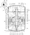
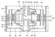
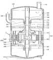
도 1은 본 발명에 의한 밀폐형 압축기를 보인 단면도,
도 2는 도 1에 따른 밀폐형 압축기에서 고정축과 압축유닛의 결합관계를 보인 단면도,
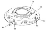
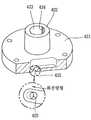
도 3은 도 1에 따른 밀폐형 압축기에서 어큠프레임과 고정축을 분해하여 보인 사시도,
도 4는 도 1에 따른 밀폐형 압축기에서 하부프레임과 하부베어링 사이에 베어링부재가 구비되는 예를 보인 단면도,
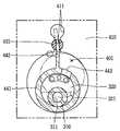
도 5는 도 1의 "I-I"선단면도,
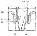
도 6은 도 1에 따른 밀폐형 압축기에서 고정축의 고정구조를 보인 단면도,
도 7은 도 1에 따른 밀폐형 압축기에서 고정축의 편심부를 보인 평면도,
도 8은 도 1에 따른 밀폐형 압축기에서 압축유닛을 보인 단면도,
도 9는 도 8에서 "II-II"선단면도,
도 10은 도 1에 따른 밀폐형 압축기에서 실린더와 회전자의 결합구조에 대한 다른 실시예를 보인 단면도,
도 11은 도 1에 따른 밀폐형 압축기에서 압축유닛에 대한 사시도,
도 12는 도 1에 따른 밀폐형 압축기에서 머플러를 보인 사시도,
도 13은 도 1에 따른 밀폐형 압축기에서 머플러를 통해 냉매가 토출되는 상태를 보인 단면도,
도 14는 도 13에 따른 밀폐형 압축기의 머플러에서 냉매의 토출구조에 대한 다른 실시예를 보인 단면도,
도 15는 도 1에 따른 밀폐형 압축기에서 상부베어링의 토출구를 파단하여 보인 사시도,
도 16은 도 1에 따른 밀폐형 압축기에서 냉매가 하부베어링을 통해 하측으로 토출되는 구조를 보인 단면도,
도 17은 도 1에 따른 밀폐형 압축기에서 냉매가 상부베어링과 하부베어링을 통해 상하 양측으로 토출되는 구조를 보인 단면도,
도 18은 도 1에 따른 밀폐형 압축기에서 롤러베인을 보인 사시도,
도 19 및 도 20은 도 18에 따른 롤러베인의 실시예들을 보인 평면도,
도 21은 도 1에 따른 밀폐형 압축기에서 압축유닛의 오일공급구조를 보인 단면도,
도 22는 도 1에 따른 밀폐형 압축기에서 상부베어링 상측에 구비되는 오일수집판을 분해하여 보인 사시도,
도 23은 도 22에 따른 밀폐형 압축기에서 오일수집판을 이용한 오일회수과정을 보인 단면도,
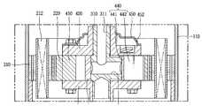
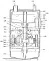
도 24는 본 발명에 따른 밀폐형 압축기에 대한 다른 실시예를 보인 단면도,
도 25는 도 24에 따른 밀폐형 압축기에서 고정자 고정구조에 대한 실시예를 확대하여 보인 단면도,
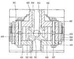
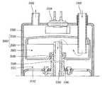
도 26은 본 발명에 따른 밀폐형 압축기에 대한 다른 실시예를 보인 단면도,
도 27은 도 26에 따른 밀폐형 압축기에서 고정축에 대한 동심도를 조절하기 위한 고정부시의 조립구조를 보인 단면도,
도 28은 도 26에 따른 밀폐형 압축기에서 터미널의 조립위치에 대한 다른 실시예를 보인 단면도,
도 29는 본 발명에 따른 밀폐형 압축기에 대한 다른 실시예를 보인 단면도,
도 30은 본 발명에 따른 밀폐형 압축기에 대한 다른 실시예를 보인 단면도.1 is a sectional view showing a hermetic compressor according to the present invention,
FIG. 2 is a cross-sectional view showing a coupling relationship between a fixed shaft and a compression unit in the hermetic compressor of FIG. 1,
FIG. 3 is a perspective view of the hermetic compressor shown in FIG. 1,
FIG. 4 is a sectional view showing an example in which a bearing member is provided between a lower frame and a lower bearing in the hermetic compressor of FIG. 1;
5 is a sectional view taken along the line "II" in Fig. 1,
FIG. 6 is a sectional view showing a fixing structure of a fixed shaft in the hermetic compressor of FIG. 1,
FIG. 7 is a plan view showing an eccentric portion of the fixed shaft in the hermetic compressor of FIG. 1,
8 is a sectional view showing a compression unit in the hermetic compressor according to Fig. 1,
Fig. 9 is a sectional view taken along the line "II-II" in Fig. 8,
FIG. 10 is a sectional view showing another embodiment of a coupling structure of a cylinder and a rotor in the hermetic compressor according to FIG. 1;
Fig. 11 is a perspective view of the compression unit in the hermetic compressor according to Fig. 1,
12 is a perspective view showing the muffler in the hermetic compressor according to Fig. 1,
FIG. 13 is a sectional view showing a state in which a refrigerant is discharged through a muffler in the hermetic compressor of FIG. 1;
FIG. 14 is a sectional view showing another embodiment of the refrigerant discharge structure in the muffler of the hermetic compressor of FIG. 13;
FIG. 15 is a perspective view of a discharge port of an upper bearing of the hermetic compressor shown in FIG. 1,
16 is a cross-sectional view illustrating a structure in which a refrigerant is discharged downward through a lower bearing in the hermetic compressor of FIG. 1;
17 is a sectional view showing a structure in which refrigerant is discharged to both upper and lower sides through an upper bearing and a lower bearing in the hermetic compressor of FIG.
FIG. 18 is a perspective view showing a roller vane in the hermetic compressor of FIG. 1,
Figures 19 and 20 are plan views of embodiments of the roller vanes according to Figure 18,
Fig. 21 is a sectional view showing the oil supply structure of the compression unit in the hermetic compressor according to Fig. 1,
FIG. 22 is a perspective view of the oil collecting plate disposed above the upper bearing of the hermetic compressor of FIG. 1,
FIG. 23 is a sectional view showing an oil recovery process using an oil collecting plate in the hermetic compressor according to FIG. 22;
24 is a sectional view showing another embodiment of the hermetic compressor according to the present invention,
Fig. 25 is an enlarged cross-sectional view of an embodiment of a stator fixing structure in the hermetic compressor of Fig. 24,
26 is a sectional view showing another embodiment of the hermetic compressor according to the present invention,
FIG. 27 is a sectional view showing an assembling structure of a stationary bushing for adjusting the concentricity with respect to the stationary shaft in the hermetic compressor according to FIG. 26;
FIG. 28 is a sectional view showing another embodiment of the assembly position of the terminal in the hermetic compressor according to FIG. 26;
29 is a sectional view showing another embodiment of the hermetic compressor according to the present invention,
30 is a sectional view showing another embodiment of the hermetic compressor according to the present invention.
이하, 본 발명에 의한 밀폐형 압축기를 첨부도면에 도시된 일실시예에 의거하여 상세하게 설명한다.Hereinafter, a hermetic compressor according to the present invention will be described in detail with reference to an embodiment shown in the accompanying drawings.
도 1 내지 도 3에 도시된 바와 같이 본 발명에 의한 밀폐형 압축기는, 밀폐된 쉘(100)의 내부공간(101)에 회전력을 발생하는 구동모터(200)가 설치되고, 상기 구동모터(200)의 중심에는 상기 쉘(100)의 내부공간(101)에서 고정되는 고정축(300)이 설치되며, 상기 고정축(300)에는 상기 구동모터(200)의 회전자(220)에 결합되어 회전하는 실린더(410)가 회전 가능하게 결합되고, 상기 쉘(100)의 내부공간(101)에는 그 쉘(100)의 내부공간(101)과 분리되는 소정의 어큠공간(accum chamber)(501)이 구비되어 상기 고정축(300)에 결합되는 어큐뮬레이터(500)가 설치된다.1 to 3, a hermetic compressor according to the present invention includes a
상기 쉘(100)은 상기 구동모터(200)가 설치되는 본체쉘((body shell)(110)과, 상기 본체쉘(110)의 상측 개구단(이하, 제1 개구단)(111)을 복개하는 동시에 상기 어큐뮬레이터(500)의 상측면을 이루는 상부캡(120)과, 상기 본체쉘(110)의 하측 개구단(이하, 제2 개구단)(112)을 복개하는 하부캡(130)으로 이루어진다.The shell 100 includes a
상기 본체쉘(110)은 원통모양으로 형성되고, 그 본체쉘(110)의 중간부위에는 후술할 고정자(210)가 열박음으로 고정 결합된다. 그리고 상기 고정자(210)의 하부에는 후술할 하부베어링(430)을 반경방향으로 지지하는 하부프레임(140)이 상기 고정자(210)와 동시에 본체쉘(110)에 열박음되어 고정된다. 상기 하부프레임(140)은 그 중앙에 상기 하부베어링(430)이 회전 가능하게 삽입되어 후술할 고정축(300)을 반경방향으로 지지하도록 베어링구멍(141)이 형성되고, 상기 하부프레임(140)의 가장자리는 절곡되어 그 외주면이 상기 본체쉘(110)에 밀착되도록 고정부가 형성된다. 상기 하부프레임(140)의 외측 선단면, 즉 고정부(142)의 끝단은 상기 고정자(210)의 저면에 밀착되어 그 고정자(210)를 축방향으로 지지할 수 있도록 본체쉘(110)에 고정된다.The
여기서, 상기 하부프레임(140)은 판금으로 제작될 수도 있고 주물로 제작될 수도 있다. 상기 하부프레임(140)이 판금으로 제작되는 경우에는 도 4에서와 같이 그 하부프레임(140)과 하부베어링(430) 사이가 윤활될 수 있도록 볼베어링이나 부시와 같은 별도의 베어링부재(145)를 설치하는 것이 바람직하지만, 상기 하부프레임(140)이 주물로 제작되는 경우에는 상기 하부프레임(140)의 베어링구멍(141)을 정밀가공할 수 있으므로 별도의 베어링부재를 설치할 필요가 없다. 상기 하부프레임(140)과 하부베어링(430) 사이에 베어링부재(145)가 설치되는 경우에는 도 4에서와 같이 상기 하부프레임(140)의 베어링구멍(141) 끝단에 상기 베어링부재(145)를 지지하도록 베어링지지부(143)가 절곡 형성되는 것이 바람직할 수 있다.Here, the
상기 본체쉘(110)의 상단에는 상기 어큐뮬레이터(500)의 하측면을 이루는 어큠프레임(accum frame)(150)이 결합될 수 있다.An
상기 어큠프레임(150)은 그 중앙에 후술할 고정부시(upper bush)(160)가 관통되어 결합되도록 부시구멍(151)이 형성된다. 도 5에서와 같이 상기 부시구멍(151)은 그 내경이 후술할 고정부시(160)의 축수부(161) 외경보다 크게 형성되어 후술할 고정축(300)의 중심조절(centering) 작업시 여유간격(t1)을 가지도록 하는 것이 바람직할 수 있다.A
그리고 상기 부시구멍(151)의 주변에는 도 5에서와 같이 상기 고정부시(160)를 볼트(155)로 체결하기 위한 관통공(152)이 형성된다. 상기 관통공(152)은 상기 부시구멍(151)과 같이 상기 고정축(300)의 중심조절 작업시 여유간격(t2)을 가지도록 상기 볼트(155)의 직경 또는 상기 고정부시(160)에 구비된 체결공(166)의 직경보다 크게 형성되는 것이 바람직하다.5, a through
그리고 상기 어큠프레임(150)의 가장자리는 상기 본체쉘(110)과 상부캡(120)의 이음단과 중첩되는 길이, 즉 상기 상부캡(120)의 내주면까지 삽입될 수 있는 길이로 절곡된 고정단부(153)가 형성된다. 그리고 상기 어큠프레임(150)의 고정단부(153)가 상기 본체쉘(110)의 내주면과 상부캡(120)의 내주면에 밀착되어 그 본체쉘(110)과 상부캡(120)의 이음단과 함께 용접 결합됨으로써 상기 본체쉘(110)과 상부캡(120) 그리고 어큠프레임(150)이 한 번에 용접되면서도 실링길이가 길어져 쉘(100)의 밀봉력이 향상될 수 있다. 여기서, 상기 어큠프레임(150)의 고정단부(153) 외주면에는 상기 본체쉘(110)과 상부캡(120)의 이음단 사이에 개재되도록 고정돌조(154)가 형성될 수 있다.The edge of the
상기 고정부시(160)는 상기 어큠프레임(150)의 부시구멍(151)에 삽입되는 축수부(161)와, 상기 축수부(161)의 외주면 중간에서 반경방향으로 확장 형성되는 플랜지부(165)로 이루어진다.The fixed
상기 축수부(161)는 그 중앙에 상기 고정축(300)이 축방향으로 관통되어 삽입되는 축수구멍(162)이 형성되고, 상기 축수구멍(161)의 중간에는 상기 어큐뮬레이터(500)의 어큠공간(501)과 상기 쉘(100)의 내부공간(101) 사이를 실링하기 위한 실링부재(167)가 압입되어 결합된다. 그리고, 도 5 및 도 6에서와 같이 상기 축수부(161)의 상단측에는 상기 고정축(300)을 걸어 고정하기 위한 고정핀(168)이 삽입되도록 핀고정공(163)이 형성된다. 여기서 상기 고정부시(160)와 고정축(300)은 전술한 고정핀(168) 외에 고정볼트를 사용하여 고정할 수도 있고, 경우에 따라서는 고정링을 이용하여 고정할 수도 있다. 그리고 상기 축수부(161)의 중간, 즉 상기 플랜지부(165)와 인접된 부위에는 상기 어큐뮬레이터(500)에서 분리된 오일을 상기 고정축(300)의 냉매흡입유로(301)를 통해 압축공간(401)으로 회수하기 위한 배유공(164)이 형성된다.The
상기 플랜지부(165)는 그 반경방향 폭이 상기 축수부(161)가 반경방향으로 움직일 수 있는 유동 폭 보다 크게 형성되는 것이 상기 고정부시(160)가 고정축(300)과 함께 중심조절을 할 때 여유너비를 가질 수 있어 바람직하다. 상기 플랜지부(165)에는 상기 어큠프레임(150)의 관통공(152)에 대응하도록 복수 개의 체결공(166)이 형성되고, 상기 체결공(166)은 관통공(152)의 직경보다 작게 형성된다.The
상기 상부캡(120)은 그 가장자리가 절곡되어 상기 본체쉘(110)의 제1 개구단(111)에 대향되어 상기 어큠프레임(150)의 고정부(152)와 함께 상기 본체쉘(110)의 제1 개구단(111)에 용접 결합된다. 그리고 상기 상부캡(120)에는 냉매를 냉동사이클에서 어큐뮬레이터(500)로 안내하는 흡입관(102)이 관통 결합된다. 상기 흡입관(102)은 상기 상부캡(120)의 일측에 편심지게, 즉 후술할 고정축(300)의 냉매흡입유로(301)와 동심상에 일치하지 않도록 배치되는 것이 액냉매가 압축공간(401)으로 흡입되는 것을 방지할 수 있어 바람직하다. 그리고 상기 고정자(210)와 어큠프레임(150) 사이의 본체쉘(110)에는 상기 압축유닛(300)에서 상기 쉘(100)의 내부공간(101)으로 토출되는 냉매를 냉동사이클로 안내하는 토출관(103)이 관통 결합된다.The
상기 하부캡(130)은 그 가장자리가 절곡되어 상기 본체쉘(110)의 제2 개구단(112)에 용접 결합된다.The
도 1에서와 같이, 상기 구동모터(200)는 상기 본체쉘(100)에 고정되는 고정자(210)와, 상기 고정자(210)의 내부에 회전 가능하게 배치되는 회전자(220)로 이루어진다.1, the driving
상기 고정자(210)는 환형으로 형성되는 다수 장의 스테이터시트가 소정의 높이만큼 적층되고, 그 내주면에 구비되는 티스에는 코일(230)이 권선된다. 그리고 상기 고정자(210)는 상기 본체쉘(110)에 열박음되어 일체로 고정 결합되고, 그 고정자(210)의 저면에는 상기 하부프레임(140)의 선단면이 밀착되어 고정된다.In the
상기 고정자(210)의 가장자리에는 상기 쉘(100)의 내부공간(101)에서 회수되는 오일이 그 고정자(210)를 통과하여 상기 하부캡(130)으로 모일 수 있도록 오일회수구멍(211)이 관통 형성될 수 있다. 상기 고정자(210)의 오일회수구멍(211)은 상기 하부프레임(140)의 오일회수구멍(146)과 연통된다.An
상기 회전자(220)는 상기 고정자(210)의 내주면에 일정 공극을 두고 배치되며 그 중앙에 후술할 실린더(410)가 일체로 결합된다. 상기 회전자(220)와 실린더(410)는 후술할 상부베어링 플레이트(이하, 상부베어링으로 약칭함)(420) 또는 하부베어링 플레이트(이하, 하부베어링으로 약칭함)(430)과 함께 볼트로 결합될 수도 있고, 상기 회전자(220)와 실린더(410)를 소결과 같은 공법을 이용하여 일체로 성형할 수도 있다.The
도 1 내지 도 3에서와 같이 상기 고정축(300)은 축방향으로 소정의 길이를 갖고 그 양단이 상기 쉘(100)에 대해 고정되는 축부(310)와, 상기 축부(310)의 중간에서 반경방향으로 편심지게 확장되고 상기 실린더(410)의 압축공간(401)에 수용되어 그 압축공간(401)의 체적을 가변시키는 편심부(320)로 이루어진다. 여기서, 상기 축부(310)는 그 축중심이 상기 실린더(410)의 회전중심 또는 회전자(220)의 회전중심 또는 고정자(210)의 반경중심 또는 쉘(100)의 반경중심과 일치하도록 형성되는 반면 상기 편심부(320)는 그 축중심이 상기 실린더(410)의 회전중심 또는 회전자(220)의 회전중심 또는 고정자(210)의 반경중심 또는 쉘(100)의 반경중심과 편심지도록 형성된다.1 to 3, the fixed
상기 축부(310)의 상단은 상기 어큐뮬레이터(500)의 어큠공간(501) 안으로 삽입되는 반면 상기 축부(310)의 하단은 상기 상부베어링(420)과 하부베어링(430)을 반경방향으로 지지하도록 그 상부베어링(420)과 하부베어링(430)을 축방향으로 관통하여 회전 가능하게 결합된다.The upper end of the
상기 축부(310)의 내부에는 그 상단이 상기 어큐뮬레이터(500)의 어큠공간(501)에 연통되어 상기 냉매흡입유로(301)를 이루는 제1 흡입안내구멍(311)이 축방향으로 소정의 깊이, 대략 편심부(320)의 하단까지 형성되고, 상기 편심부(320)에는 일단이 상기 제1 흡입안내구멍(311)과 연통되고 타단이 상기 압축공간(401)에 연통되어 상기 제1 흡입안내구멍(311)과 함께 냉매흡입유로(301)를 이루는 제2 흡입안내구멍(321)이 반경방향으로 관통 형성된다.The upper end of the
그리고 도 6에서와 같이 상기 축부(310)의 상측, 정확하게는 상기 고정부시(160)의 핀고정공(163)에 대응되는 부위에는 도 7에서와 같이 상기 고정핀(168)이 관통되도록 핀구멍(312)이 반경방향으로 관통 형성되고, 상기 핀구멍(312)의 하측, 즉 상기 어큠프레임(150)의 바닥면보다 낮은 상기 부시구멍(151)의 높이에는 상기 어큐뮬레이터(500)에 고인 오일을 압축공간(401)으로 회수하기 위한 배유공(313)이 상기 제1 흡입안내구멍(311)에 연통되도록 형성될 수 있다.6, the fixing
상기 편심부(320)는 도 7에서와 같이 소정의 두께를 갖는 원판 모양으로 형성되어 상기 축부(310)의 축중심에 대해 반경방향으로 편심지게 형성된다. 여기서, 상기 편심부(320)는 상기 고정축(310)이 쉘(100)에 고정 결합됨에 따라 상기 편심부(320)의 편심량은 압축기 용량에 따라 충분히 크게 형성될 수 있다.7, the
그리고 상기 편심부(320)의 내부에는 상기 제1 흡입안내구멍(311)과 함께 냉매흡입유로(301)를 이루는 제2 흡입안내구멍(321)이 반경방향으로 관통 형성된다. 상기 제2 흡입안내구멍(321)은 도면에서와 같이 일직선으로 관통하여 복수 개가 형성될 수도 있지만, 경우에 따라서는 상기 제1 흡입안내구멍(311)에 대해 한 쪽 방향으로만 관통하여 형성될 수도 있다.In the
그리고 상기 편심부(320)의 외주면에는 상기 제2 흡입안내구멍(321)을 통해 반경방향으로 안내되는 냉매가 후술할 롤러베인(440)의 흡입구(443)와 항상 연통될 수 있도록 흡입안내홈(322)이 환형으로 형성될 수 있다. 하지만, 상기 흡입안내홈(322)은 경우에 따라서는 상기 롤러베인(440)의 내주면에 형성될 수도 있고, 상기 롤러베인(440)의 내주면과 편심부(320)의 외주면에 모두 형성될 수도 있다. 그리고 상기 흡입안내홈(322)은 반드시 환형일 필요는 없고 원주방향으로 긴 원호형상으로 형성될 수도 있다.The refrigerant guided in the radial direction through the second
상기 고정축(300)의 편심부(320)에는 상기 회전자(220)와 결합되어 함께 회전하면서 냉매를 압축하도록 압축유닛(400)이 결합된다. 도 8 및 도 9에서와 같이, 상기 압축유닛(400)은 실린더(410)와, 그 실린더(410)의 양측에 결합되어 함께 압축공간(401)을 형성하는 상부베어링(420) 및 하부베어링(430)과, 상기 실린더(410)와 편심부(320) 사이에 구비되어 압축공간(401)을 가변시키면서 냉매를 압축하는 롤러베인(440)으로 이루어진다.The
상기 실린더(410)는 그 내부에 압축공간(401)이 형성되도록 환형으로 형성되고, 상기 실린더(410)의 회전중심은 상기 고정축(300)의 축중심과 일치하도록 설치된다. 그리고 상기 실린더(410)의 일측에는 상기 롤러베인(440)이 회전을 하면서 반경방향으로 미끄러질 수 있도록 삽입되는 베인슬롯(411)이 형성된다. 상기 베인슬롯은 롤러베인의 형상에 따라 다양하게 형성될 수 있다. 예를 들어, 후술할 롤러베인(440)의 롤러부(441)와 베인부(442)가 일체로 형성되는 경우에는 도 9 및 도 19에서와 같이 상기 베인부(442)가 베인슬롯(411)에서 회전운동을 할 수 있도록 상기 베인슬롯(411)에 회전부시(415)가 구비되는 반면, 상기 롤러부(441)와 베인부(442)가 회전 가능하게 결합되는 경우에는 도 20에서와 같이 상기 베인부(442)가 베인슬롯(411)에서 미끄럼운동을 할 수 있도록 상기 베인슬롯(411)은 미끄럼홈 형태로 형성될 수 있다.The
그리고 상기 실린더(410)는 외주면이 상기 회전자(220)에 삽입되어 일체로 결합된다. 이를 위해, 상기 실린더(410)가 상기 회전자(220)에 압입될 수도 있고, 상기 상부베어링(420) 또는 하부베어링(430)에 체결볼트(402)(403)로 체결될 수도 있다.The outer circumferential surface of the
여기서, 상기 실린더(410)와 회전자(220)가 하부베어링(430)에 의해 체결되는 경우에는 상기 하부베어링(430)의 외경이 상기 실린더(410)의 외경보다 크게 형성되는 반면 상기 상부베어링(420)의 외경은 상기 실린더(410)의 외경과 대략 동일하게 형성될 수 있다. 그리고 상기 하부베어링(430)에는 실린더(410)를 체결하기 위한 제1 관통공(437)과 회전자(220)를 체결하기 위한 제2 관통공(438)이 각각 형성된다. 상기 제1 관통공(437)과 제2 관통공(438)은 체결력을 높이기 위해 방사상 다른 선상에 형성될 수도 있지만 조립성을 고려하여 동일 선상에 형성될 수도 있다. 그리고 상기 하부베어링(430)을 통과하여 상기 실린더(410)의 일측면에 체결되는 체결볼트(402)와 상기 상부베어링(420)을 통과하여 상기 실린더(410)의 타측면에 체결되는 체결볼트(403)의 체결깊이는 서로 동일하게 형성될 수 있다.Here, when the
한편, 상기 실린더(410)는 도 10에서와 같이 회전자(220)와 일체로 성형될 수 있다. 예를 들어, 상기 실린더(410)와 회전자(220)를 분말야금이나 다이캐스팅과 같은 공법을 통해 일체로 성형할 수 있다. 이 경우, 상기 실린더(410)와 회전자(220)는 동일 재질로 형성할 수도 있지만, 서로 다른 재질로 형성할 수도 있다. 상기 실린더(410)와 회전자(220)를 다른 재질로 형성할 경우에는 실린더(410)의 내마모성을 고려하여 그 실린더(410)는 회전자(220)에 비해 상대적으로 내마모성이 좋은 재질로 형성할 수 있다. 그리고 상기 실린더(410)와 회전자(220)가 일체로 형성될 경우에는 도 10에서와 같이 상기 상부베어링(420)과 하부베어링(430)은 실린더(410)의 외경과 동일하거나 작게 형성될 수 있다.Meanwhile, the
그리고, 도 9에서와 같이 상기 실린더(410)와 회전자(220) 사이의 결합력을 높일 수 있도록 상기 실린더(410)의 외주면와 회전자(220)의 내주면에는 각각 돌출부(412)와 홈부(221)(도면에서는 실린더에 돌출부가, 회전자에 홈부)가 형성될 수 있다. 그리고 상기 실린더(410)의 돌출부(412)가 형성되는 원주각 범위에는 상기 베인슬롯(411)이 형성될 수 있다. 그리고 상기 돌출부(412)와 홈부(221)는 복수 개가 형성될 수 있다. 상기 돌출부(412)와 홈부(221)가 각각 복수 개 형성되는 경우에는 원주방향을 따라 등간격으로 형성되는 것이 자속불균형을 해소할 수 있어 바람직할 수 있다.9,
도 11에서와 같이, 상기 상부베어링(420)은 고정판부(421)의 상면 중앙에 상기 고정축(300)의 축부(310)를 반경방향으로 지지하는 축수부(422)가 소정의 높이만큼 상향 돌출되어 형성된다. 여기서, 상기 회전자(220)와 실린더(410) 그리고 상기 상부베어링(420)과 후술할 하부베어링(430)으로 이루어지는 회전체가 상기 고정축(300)의 축중심과 일치하는 회전중심을 갖게 되므로 상기 상부베어링(420)의 축수부(422) 길이 또는 후술할 하부베어링(430)의 축수부(432) 길이는 길게 형성하지 않아도 상기 회전체를 원활하게 지지될 수 있다.11, the
상기 고정판부(421)는 원판모양으로 형성되어 상기 실린더(410)의 상면에 고정되고, 상기 축수부(422)는 축수구멍(423)이 축방향으로 관통 형성되어 상기 고정축(300)에 대해 회전 가능하게 결합된다. 상기 축수구멍(423)의 내주면에는 후술할 오일그루브(424)가 나선형으로 형성된다.The fixed
상기 축수부(422)의 일측에는 상기 압축공간(401)과 연통되도록 토출구(425)가 형성되고, 상기 토출구(425)의 출구단에는 토출밸브(426)가 설치된다. 그리고 상기 메이베어링(420)의 상측에는 상기 토출구(425)를 통해 토출되는 냉매의 토출소음을 감쇄시키는 머플러(450)가 결합된다.A
도 12에서와 같이, 상기 머플러(450)는 적어도 한 개 이상의 소음공간(451)이 형성되고, 상기 소음공간(451)의 일측에는 냉매가 쉘(100)의 내부공간(101)으로 배출되도록 배출통공(452)이 형성된다. 상기 배출통공(452)은 단순 구멍으로 형성될 수도 있지만 상기 압축공간(401)에서 토출되는 냉매에서 오일을 분리할 수 있도록 메시와 같은 분리부재(453)가 설치될 수도 있다.12, at least one
그리고 상기 배출통공(452)은 축방향으로 관통 형성될 수도 있지만, 상기 고정자(210)의 코일(212)이 머플러(450)의 횡방향 바깥쪽에 배치되는 점을 고려하여 도 12 및 도 13에서와 같이 상기 압축공간(401)에서 쉘(110)의 내부공간(101)으로 토출되는 냉매가 상기 코일(212)이 있는 방향으로 안내될 수 있도록 반경방향으로 형성되는 것이 모터 효율을 높이는데 바람직할 수 있다. 상기 배출통공(452)이 반경방향으로 형성되기 위해서는 도 13에서와 같이 상기 상부베어링(420)의 외주면에 대향하는 상기 소음공간(451)의 측면에 관통 형성될 수도 있지만, 도 14에서와 같이 상기 소음공간(451)의 상측면에서 반경방향으로 곡면지거나 경사지도록 절개된 안내면부(454)가 형성될 수도 있다.12 and 13 in consideration of the fact that the
여기서, 상기 배출통공(452)과 토출구(425)는 모두 회전체인 베어링과 머플러에 설치됨에 따라 상기 배출통공(452)과 토출구(425)는 도 15에서와 같이 회전방향에 순방향으로 경사지거나 또는 라운드지게 형성되는 것이 토출저항을 줄일 수 있다.Since the discharge through
도 8 및 도 11에서와 같이 상기 하부베어링(430)은 상기 상부베어링(420)과 같이 대칭되도록 고정판부(431)의 하면 중앙에 상기 고정축(300)의 축부(310)를 지지하는 축수부(432)가 소정의 높이만큼 하향 돌출되어 형성된다. 그리고, 상기 회전자(220)와 실린더(410) 그리고 상기 상부베어링(420)과 하부베어링(430)으로 이루어지는 회전체가 상기 고정축(300)의 축중심과 일치하는 회전중심을 갖게 되므로 상기 하부베어링(430)의 축수부(432) 길이는 상기 상부베어링(420)의 축수부(422)와 같이 길게 형성하지 않아도 상기 회전체를 원활하게 지지될 수 있다.8 and 11, the
상기 고정판부(431)는 원판모양으로 형성되어 상기 실린더(410)의 하면에 고정되고, 상기 축수부(432)는 축수구멍(433)이 축방향으로 관통 형성되어 상기 고정축(300)에 대해 회전 가능하게 결합된다. 상기 축수구멍(433)의 내주면에는 후술할 오일그루브(434)가 나선형으로 형성된다.The fixed
여기서, 상기 실린더(410)와 회전자(220)가 분리 형성되는 경우에는 그 실린더(410)와 회전자(220)가 상기 하부베어링(430)의 고정판부(431)에 의해 결합될 수 있다. 물론, 상기 실린더(410)와 회전자(220)는 상기 상부베어링(420)에 의해서도 일체로 결합될 수 있다.When the
그리고 상기 토출구는 상부베어링(420)에 형성되지 않고, 도 16에서와 같이 상기 하부베어링(430)에 형성될 수 있다. 이 경우 상기 머플러(450) 역시 하부베어링(430)에 결합되고, 상기 머플러(450)의 배출통공(452)도 소음공간(451)에서 축방향으로 관통되거나 또는 반경방향으로 관통되어 형성될 수 있다. 특히, 상기 토출구(435)가 하부베어링(430)에 형성되는 경우에는 상기 머플러(450)의 배출통공(452)이 축방향으로 관통되는 경우 냉매가 저장된 오일과 간섭될 수 있으므로 코일을 향해 반경방향으로 관통되는 것이 냉매와 오일의 간섭이나 코일의 냉각효과를 높일 수 있어 바람직하다.The discharge port is not formed in the
그리고 상기 토출구(425)(435)는 도 17에서와 같이 상부베어링(420)과 하부베어링(430)에 모두 형성될 수도 있다. 이 경우 상기 상부베어링(420)과 하부베어링(430)에 형성되는 각각의 토출구(425)(435)는 동일 수직선상, 즉 동일 원주각에 형성될 수도 있지만, 용량 가변식 압축기와 같은 경우에는 양쪽 토출구(425)(435)가 원주방향으로 위상차를 갖도록 서로 다른 원주각에 형성될 수도 있다. 그리고 상기 토출구(425)(435)가 양쪽 베어링(420)(430)에 모두 형성되는 경우에는 상기와 같은 머플러(450)를 각각의 베어링(420)(430)에 모두 설치될 수 있다. 그리고 상기 토출구(425)(435)가 동일한 원주각에 형성되는 경우에는 양쪽 토출구(425)(435)에서 냉매가 동시에 토출되도록 상기 토출밸브(426)(436)들의 탄성계수를 동일하게 형성할 수도 있고 용량 가변을 위해 서로 다른 탄성계수를 갖도록 형성할 수도 있다. 물론 양쪽 토출구(425)(435)가 위상차를 갖도록 형성되는 경우에도 상기 토출밸브(426)(436)들의 탄성계수는 압축기에 따라 동일하게 형성할 수도 있고 상이하게 형성할 수도 있다.The
도 18에서와 같이, 상기 롤러베인(440)은 상기 고정축(300)의 편심부(320)에 회전 가능하게 결합되는 롤러부(441)와, 상기 롤러부(441)에 일체로 결합되거나 일체로 성형되어 상기 실린더(310)의 베인슬롯(411)에 미끄러지게 삽입되는 베인부(442)로 이루어진다. 그리고 상기 롤러부(441)와 베인부(442)의 상하 양 측면에는 실링홈(444)이 형성되고, 상기 실링홈(444)에는 압축되는 냉매가 축방향으로 누설되는 것을 방지할 수 있도록 실링부재(445)가 삽입될 수 있다.18, the
상기 롤러부(441)는 외주면 일부가 상기 실린더(310)의 내주면에 접하고 내주면 전체가 상기 편심부(320)에 접하도록 환형으로 형성되고, 상기 베인부(442)를 중심으로 원주방향 일측, 즉 상기 상부베어링(420)의 토출구(425) 반대쪽에서 상기 편심부(320)의 제2 흡입안내구멍(321)과 연통되는 흡입구(443)가 형성된다. 하지만, 상기 고정축(300)의 편심부(320) 외주면에 흡입안내홈(322)이 환형으로 형성되는 경우에는 상기 흡입구(443)가 흡입안내홈(322)을 통해 제2 흡입안내구멍(321)과 연속으로 연통될 수 있다. 여기서, 상기 흡입안내홈은 상기 롤러베인(440)의 내주면에 형성될 수도 있고 양쪽에 모두 상기 흡입안내홈(미도시)이 형성될 수 있다.The
상기 베인부(442)는 직육면체 형상으로 형성되어 도 19에서와 같이 일단이 상기 롤러부(441)의 외주면에 일체로 성형될 수도 있다. 이 경우, 상기 베인슬롯(411)은 한 개 이상(도면에서는 2개의 베인슬롯이 반경방향으로 형성됨)의 원형홈으로 형성되고, 상기 베인슬롯(411)에 한 개 이상의 회전부시(415)가 회전 가능하게 삽입되어 결합될 수 있다. 상기 회전부시(415)의 외주면은 상기 베인슬롯(411)의 내주면에 미끄러져 회전하도록 원형으로 형성되고, 상기 회전부시(415)의 내주면은 상기 베인부(442)의 양측면에 길이방향으로 미끄러지도록 평면으로 형성될 수 있다.The
하지만, 상기 베인부(442)는 도 20에서와 같이 일단에 원형 단면 형상으로 회동돌부(446)가 형성되고 상기 롤러부(441)의 외주면에는 상기 회동돌부(446)가 회전 가능하게 삽입되어 빠지지 않도록 결합되는 회동홈부(447)가 형성될 수도 있다. 이 경우, 상기 회동돌부(446)와 회동홈부(447) 사이에는 내마모성을 갖는 얇은 윤활부재(미부호)를 삽입하는 것이 바람직할 수 있다.20, the
한편, 도 1 및 도 11 및 도 21에서와 같이, 상기 하부베어링(430)의 축수구멍(433) 하단에는 상기 하부캡(130)에 고인 오일을 펌핑하기 위한 오일피더(460)가 결합되고, 상기 오일피더(460)의 출구는 상기 하부베어링(430)의 오일그루브(434)와 연통된다.1, 11, and 21, an
그리고 상기 편심부(320)의 저면에는 상기 하부베어링(430)의 오일그루브(434)와 연통되도록 하측 오일포켓(323)이 형성되고, 상기 하측 오일포켓(323)의 내부에는 그 하측 오일포켓(323)에 고인 오일을 상기 상부베어링(420)의 오일그루브(424)로 안내하기 위한 오일통공(325)이 축방향으로 관통 형성된다. 그리고 상기 편심부(320)의 상측면에는 상기 오일통공(325)과 연통되도록 상측 오일포켓(324)이 형성되고, 상기 상측 오일포켓(324)은 상기 상부베어링(420)의 오일그루브(424)와 연통되도록 형성된다.A
상기 오일포켓(323)(324)들의 단면적은 상기 오일통공(325)들의 전체 단면적보다 넓게 형성되고, 상기 오일통공(325)은 상기 제2 흡입안내구멍(321)과 중첩되지 않도록 형성되는 것이 냉매와 오일을 원활하게 이동시키는데 바람직하다.Sectional area of the oil pockets 323 and 324 is formed wider than the entire cross-sectional area of the oil passage holes 325 and the
그리고 상기 머플러(450)가 하부베어링(430)에 설치되어 압축된 냉매가 하측으로 토출되는 경우에는 도 22에서와 같이, 상기 상부베어링(420)의 축수구멍(423)으로 흡상되어 윤활을 마친 오일을 수집하여 상기 베인슬롯(411)과 베인부(442) 사이로 공급하기 위한 오일수집판(470)이 상기 상부베어링(420)의 상측에 설치될 수 있다. 이 경우, 상기 상부베어링(420)에는 상기 오일수집판(470)에 의해 수집되는 오일이 상기 베인슬롯(411)과 베인부(442) 사이로 안내되도록 오일안내구멍(427)이 형성될 수 있다.22, when the
상기 오일수집판(470)은 도 23에서와 같이, 그 중앙부위가 상기 상부베어링(420)의 축수부(422)의 상단을 감싸도록 오일수집부(471)가 돌출 형성되고, 상기 오일수집부(471)의 하단 일측에서 상기 실린더(410)의 베인슬릿(411) 또는 상기 베인슬롯(411)에 연통되는 오일안내구멍(427)을 향해 연장되어 상기 오일수집부(471)에서 수집된 오일을 상기 베인슬롯(정확하게는, 베인슬롯의 후단)(411) 또는 오일안내구멍(427)으로 안내하는 오일안내부(472)가 형성된다. 상기 오일안내부(472)는 상기 오일수집부(471)의 하단에서 확장되어 상기 상부베어링(420)의 상면에 고정되는 고정부(473)의 일부가 볼록하게 형성되어 오일유로를 이루도록 형성된다. 그리고 상기 오일안내부(472)는 내부에 상기 베인슬롯(411) 또는 급유공(412)이 수용되도록 형성된다.23, the
여기서, 도면으로 도시하지는 않았으나, 상기 상부베어링에 토출구가 형성되는 경우에는 상기 머플러의 소음공간이 상기 상부베어링의 축수부를 수용할 수 있는 높이로 형성하거나 또는 상기 소음공간에 오일수집부를 형성하여 상기 상부베어링의 토출구를 통해 배출되는 오일을 포집하도록 형성할 수 있다.Here, although not shown in the drawings, when the discharge port is formed in the upper bearing, the noise space of the muffler may be formed at a height capable of accommodating the bearing portion of the upper bearing, or an oil collecting portion may be formed in the noise space, So that the oil discharged through the discharge port of the bearing can be collected.
한편, 상기 어큐률레이터(500)는 앞서 살펴본 바와 같이 상기 어큠프레임(150)이 상기 본체쉘(110)의 내주면에 밀봉 결합됨에 따라 상기 쉘(100)의 내부공간(101)에 형성될 수 있다.The
상기 어큠프레임(150)은 원형 판체에서 가장자리를 절곡하여 그 외주면은 상기 본체쉘(110)의 내주면과 상부캡(120)의 내주면에 밀착되도록 하는 동시에 그 본체쉘(110)과 상부캡(120)의 이음부에 용접 결합함으로써 상기 어큐뮬레이터(500)의 어큠공간(501)이 밀봉되도록 한다.The
상기와 같은 본 발명에 의한 밀폐형 압축기는 다음과 같이 동작된다.The hermetic compressor according to the present invention operates as follows.
즉, 상기 구동모터(200)의 고정자(210)에 전원을 인가하여 상기 회전자(220)가 회전하면, 상기 회전자(220)에 상부베어링(420) 또는 하부베어링(430)으로 결합된 실린더(410)가 상기 고정축(300)에 대해 회전을 하게 된다. 그러면 상기 실린더(410)에 미끄러지게 결합되는 롤러베인(440)이 상기 실린더(410)의 압축공간(401)을 흡입실과 토출실으로 분리하면서 흡입력을 발생하게 된다.That is, when power is applied to the
그러면 상기 흡입관(102)을 통해 냉매가 어큐뮬레이터(500)의 어큠공간(501)으로 흡입되고, 이 냉매는 그 어큐뮬레이터(500)의 어큠공간(501)에서 가스냉매와 액냉매로 분리되어 가스냉매는 상기 고정축(300)의 제1 흡입안내구멍(311)과 제2 흡입안내구멍(321) 그리고 흡입안내홈(322)과 상기 롤러베인(440)의 흡입구(443)를 통해 상기 압축공간(401)의 흡입실으로 흡입된다. 상기 흡입실으로 흡입되는 냉매는 상기 실린더(410)가 회전을 지속함에 따라 상기 롤러베인(440)에 의해 토출실로 이동하면서 압축되어 상기 토출구(425)를 통해 쉘(110)의 내부공간(101)으로 토출되고, 이 쉘(100)의 내부공간(101)으로 토출되는 냉매는 토출관(103)을 통해 냉동사이클 장치로 배출되는 일련의 과정을 반복하게 된다. 이때, 상기 하부베어링(430)은 상기 회전자(220)와 함께 고속으로 회전을 하면서 그 하부베어링(430)의 하단에 구비된 오일피더(460)가 상기 하부캡(130)의 오일을 펌핑하여 하부베어링(430)의 오일그루브(434), 하측 오일포켓(323), 오일통공(325), 상측 오일포켓(324) 그리고 상부베어링(420)의 오일그루브(424) 등을 차례대로 거쳐 각각의 습동면에 공급하게 된다.The refrigerant is sucked into the
여기서, 상기 압축기가 조립되는 순서는 다음과 같다.Here, the assembling order of the compressors is as follows.
즉, 상기 구동모터(200)의 고정자(210)와 하부프레임(140)이 본체쉘(110)에 열박음으로 고정된 상태에서 상기 고정부시(160)에 고정축(300)을 삽입하여 고정핀(168)으로 고정한다. 상기 고정축(300)에는 상기 회전자(220)와 실린더(410) 그리고 양측 베어링(420)(430)이 결합된다.That is, when the
다음, 상기 고정자(210)와 회전자(220)의 동심도를 유지한 상태에서 상기 본체쉘(110)에 어큠프레임(150)을 삽입하여 그 어큠프레임(150)에 상기 고정부시(160)를 체결하고, 상기 어큠프레임(150)을 본체쉘(110)에 3점 용접하여 임시 고정한다.Next, the
다음, 상기 본체쉘(110)의 제2 개구단(112)에 하부캡(130)을 압입하고 그 하부캡(130)과 본체쉘(110)의 이음부를 원주 용접하여 밀봉 조립한다.Next, the
다음, 상기 본체쉘(110)의 제1 개구단(111)에 상부캡(120)을 압입하고 그 상부캡(120)과 본체쉘(110)의 이음부를 상기 어큠프레임(150)과 함께 원주 용접하여 상기 어큐뮬레이터(500)의 어큠공간(501)을 형성하면서 상기 쉘(100)의 내부공간(101)을 밀봉 조립한다.Next, the
이렇게 하여, 상기 어큐뮬레이터가 쉘의 내부공간에 설치됨에 따라 쉘의 내부공간을 활용할 수 있고 이를 통해 어큐뮬레이터를 포함하는 압축기의 크기를 줄일 수 있다.Thus, since the accumulator is installed in the inner space of the shell, the internal space of the shell can be utilized, thereby reducing the size of the compressor including the accumulator.
또, 상기 어큐뮬레이터의 조립공정과 쉘의 조립공정을 일원화함으로써 압축기의 조립공정을 간소화할 수 있을 뿐만 아니라, 상기 고정축을 어큐뮬레이터에 결합하여 그 어큐뮬레이터의 어큠공간과 상기 고정축의 냉매흡입유로를 직접 연결함으로써 냉매의 누설을 미연에 방지하여 압축기 성능이 향상될 수 있다.In addition, the assembling process of the accumulator and the assembling process of the shell are integrated so that the assembling process of the compressor can be simplified, and the fixing shaft is coupled to the accumulator, and the space of the accumulator and the refrigerant suction passage of the fixed shaft are directly connected The leakage of the refrigerant can be prevented beforehand and the performance of the compressor can be improved.
또, 상기 어큐뮬레이터를 포함한 압축기를 실외기에 설치할 때 그 어큐뮬레이터를 포함한 압축기의 설치에 필요한 면적을 최소화하여 실외기의 설계 자유도를 높일 수 있다.When the compressor including the accumulator is installed in the outdoor unit, the area required for installing the compressor including the accumulator is minimized, and the degree of freedom of design of the outdoor unit can be increased.
또, 상기 어큐뮬레이터의 무게중심이 그 어큐뮬레이터를 포함하는 압축기 전체의 무게중심과 일치하는 위치에 설치되도록 하여 상기 어큐뮬레이터로 인한 압축기의 진동 소음을 감쇄시킬 수 있다.In addition, the center of gravity of the accumulator is installed at a position coinciding with the center of gravity of the entire compressor including the accumulator, so that the vibration noise of the compressor due to the accumulator can be attenuated.
또, 상기 고정축의 축중심과 실린더의 회전중심이 일치하도록 하면서 상기 고정축에 압축공간을 형성하기 위한 편심부를 구비함으로써 넓은 압축공간을 확보할 수 있고 이를 통해 압축기 용량을 증가시킬 수 있다.Further, since the axial center of the fixed shaft and the rotational center of the cylinder coincide with each other and the eccentric portion for forming the compression space in the fixed shaft is provided, a wide compression space can be ensured and the compressor capacity can be increased.
또, 상기 고정축의 양단이 쉘에 고정되는 프레임에 의해 지지됨에 따라 회전체의 회전시 발생되는 진동에 의해 상기 고정축이 움직이는 것을 효과적으로 억제할 수 있고 이를 통해 압축기 진동을 줄여 장수명과 신뢰성을 높일 수 있을 뿐만 아니라 상기 고정축과 회전체 사이에서의 베어링 사용량을 줄여 재료비용을 낮출 수 있다.Further, since both ends of the fixed shaft are supported by the frame fixed to the shell, it is possible to effectively suppress the movement of the fixed shaft due to the vibration generated during rotation of the rotating body, thereby reducing the vibration of the compressor, Not only the amount of bearing used between the fixed shaft and the rotating body can be reduced, and the material cost can be reduced.
또, 상기 하부베어링과 크랭크축의 편심부 그리고 상부베어링에 오일유로를 형성함으로써 상기 오일유로의 길이가 짧아지게 되고 이로 인해 원심력의 감소되는 저속운전에서도 오일을 습동부로 원활하게 공급할 수 있어 압축기의 마찰손실을 줄일 수 있다.In addition, since the oil passage is formed in the eccentric portion of the lower bearing and the crankshaft and in the upper bearing, the length of the oil passage is shortened so that the oil can be smoothly supplied to the sliding portion even at a low speed operation in which the centrifugal force is reduced. Loss can be reduced.
또, 상기 상부베어링의 상단에 오일수집판을 설치하여 그 오일수집판으로 수집되는 오일이 베인과 베인슬롯으로 안내되도록 함으로써 상기 쉘에 남은 오일이 베인과 베인슬롯 사이의 접촉면까지 잠기지 않더라도 상기 베인과 베인슬롯에 오일을 원활하게 공급할 수 있고 이를 통해 상기 베인의 동작이 원활하게 이루어져 상기 롤러베인으로 인한 압축손실을 미연에 방지할 수 있다.In addition, the oil collecting plate may be installed at the upper end of the upper bearing to guide the oil collected by the oil collecting plate to the vane and the vane slot, so that even if the oil remaining in the shell is not locked to the contact surface between the vane and the vane slot, The oil can be smoothly supplied to the vane slot and the operation of the vane can be smoothly performed thereby to prevent the compression loss due to the roller vane in advance.
또, 상기 압축기로 인한 다른 부품과의 간섭을 최소화하여 다른 부품보다 상대적으로 무거운 압축기가 실외기의 무게 중심에 설치될 수 있도록 함으로써 실외기의 운반과 설치를 용이하게 할 수 있다.In addition, since interference with other components due to the compressor is minimized, compressors relatively heavier than other components can be installed at the center of gravity of the outdoor unit, thereby facilitating the transportation and installation of the outdoor unit.
본 발명에 의한 밀폐형 압축기에서 상기 어큐뮬레이터에 대한 다른 실시예가 있는 경우는 다음과 같다.In the hermetic compressor according to the present invention, another embodiment of the accumulator is as follows.
즉, 전술한 실시예에서는 상기 고정자(210)가 하부프레임(150)과 함께 쉘(100)의 내주면에 동시 열박음으로 고정되는 것이었으나, 본 실시예는 도 24에서와 같이 상기 고정자(1210)가 쉘(1100)에 삽입되어 고정되는 것이다.That is, in the above-described embodiment, the
상기 쉘(1100)은 상부쉘(1110)과 하부쉘(1130), 그리고 상기 상부쉘(1110)과 하부쉘(1130) 사이에 위치하는 중간쉘(1140)로 이루어지고, 상기 중간쉘(1140)에 상기 구동모터(1200)와 압축유닛(1400)이 함께 설치되며, 상기 구동축(1300)은 상기 중간쉘(1140)을 관통하여 결합된다.The shell 1100 includes an
상기 상부쉘(1110)은 원통모양으로 형성되어 그 하단은 후술할 중간쉘(1140)의 상부프레임(1141)에 결합되는 반면 그 상단은 상부캡(1120)에 의해 밀봉 결합된다. 그리고 상기 상부쉘(1110)에는 흡입관(1102)이 결합되고, 상기 상부쉘(1110)의 내주면에는 상기 상부캡(1120)과 함께 어큐뮬레이터(1500)의 어큠공간(1501)을 이루도록 어큠프레임(1150)이 밀봉 결합된다.The
상기 어큠프레임(1150)의 중앙에 부시구멍(1151)이 형성되고, 상기 부시구멍(1151)의 내주면과 고정축(1300)의 외주면 사이에는 실링부시(1510)가 구비되며, 상기 실링부시(1510)의 내주면에는 어큐뮬레이터(1500)의 어큠공간(1501)을 실링하도록 오링과 같은 실링부재(1551)가 삽입되어 결합된다.A
여기서, 상기 부시구멍(1151)은 버(burr)와 같이 하측으로 돌출되어 형성될 수 있다. 그리고 상기 부시구멍(1151)이 하측으로 돌출되어 형성되는 상기 고정축(1300)의 상단은 상기 어큠프레임(1150)의 상면 근처까지 형성되고 그 고정축(1300)의 상단에 별도의 연장관(1310)을 연결할 수 있다. 상기 연장관(1310)은 그 내경이 상기 고정축(1300)의 내경(즉, 냉매흡입유로의 내경) 보다 크게 형성하는 것이 흡입손실을 줄일 수 있어 바람직할 수 있다.Here, the
상기 하부쉘(1130)은 상단이 개구되고 하단이 막힌 컵모양으로 형성되어 개구된 상단이 후술할 하부프레임(1145)에 밀봉 결합된다.The
상기 중간쉘(1140)은 구동모터(1200)의 고정자(1210)를 중심으로 상부프레임(1141)과 하부프레임(1145)으로 구분된다. 그리고, 도 25에서와 같이 상기 상부프레임(1141)의 하단과 하부프레임(1145)의 상단에는 상기 고정자(1210)의 양측면이 삽입되어 지지되도록 반쪽 안착홈(1142)(1146)들이 서로 대칭되게 형성된다. 그리고 상기 상부프레임(1331)에는 압축유닛(1400)에서 토출된 냉매를 토출관(1103)으로 안내하기 위한 연통구멍(1333)이 형성되고, 상기 하부프레임(1335)에는 오일이 회수되도록 오일구멍(1337)이 형성된다.The
상기와 같은 본 실시예의 밀폐형 압축기에서의 다른 기본적인 구성과 그에 따른 작용효과는 전술한 실시예와 대동소이하다. 다만, 본 실시예에서는 상기 고정자(1210)가 쉘의 일부를 이루는 상부프레임(1141)과 하부프레임(1145) 사이에 삽입되어 고정됨에 따라 상기 고정자(1210)와 구동축(1300) 사이의 동심도를 맞춰 조립하기가 용이할 수 있다. 즉, 본 실시예의 밀폐형 압축기는 상기 하부프레임(1145)의 안착홈(1146)에 고정자(1210)를 안착시킨 후에 상기 회전자(1220)와 실린더(1410)가 결합된 구동축(1300)을 상기 고정자(1210)의 안쪽에 삽입하고, 상기 상부프레임(1141)의 안착홈(1142)에 상기 고정자(1210)의 상면이 지지되도록 상기 상부프레임(1141)을 고정축(1300)에 삽입하여 그 상부프레임(1141)과 하부프레임(1145)을 용접 결합하며, 상기 어큠프레임(1500)이 결합된 상부쉘(1110)을 상기 상부프레임(1141)에 삽입하여 그 상부프레임(1141)과 상부쉘(1110)을 용접하게 된다. 이때, 상기 상부프레임(1141)과 하부프레임(1145)을 용접하기 전에 상기 고정자(1210)와 회전자(1220) 사이에 갭게이지(gap gage)와 같은 간격유지부재를 끼운 후 상기 상부쉘(1110)을 반경방향으로 조절함으로써 상기 고정축(1300)이 고정자(1210)에 대해 동심도를 유지하도록 할 수 있다. 따라서, 전술한 실시예와 같이 상기 고정자와 회전자 사이에 간격유지부재를 끼운 상태에서 상기 고정부시를 반경방향으로 조절하면서 어큠프레임에 체결하여 고정하는 것에 비해 고정축의 동심도를 맞춰 조립하기가 용이하게 될 수 있다.The other basic configuration of the hermetic compressor of the present embodiment as described above and the operation and effect thereof are similar to those of the above-described embodiment. In this embodiment, the
한편, 본 실시예에서는 전술한 실시예와 같이 상기 상부프레임(1141)과 고정축(1300)을 관통하는 고정핀 또는 고정볼트 또는 고정링과 같은 고정부재(1168)를 이용하여 상기 고정축(1300)이 상부프레임(1141)에 축방향으로 지지되도록 하는 것이나, 상기 실링부시(1510)의 하단 또는 상기 어큠프레임(1150)의 부시구멍(1151) 하단을 상부프레임(1141)으로 지지하여 상기 고정축(1300)을 축방향으로 지지할 수도 있다. 이 경우, 상기 실링부시(1510)는 상기 어큠프레임(1150)의 부시구멍(1151)에 압입하여 고정하고 상기 실링부시(1510)에는 고정축(1300)을 압입하거나 다른 고정부재를 이용하여 고정할 수 있다.In the present embodiment, the
본 발명에 의한 밀폐형 압축기에 대한 또다른 실시예가 있는 경우는 다음과 같다.Another embodiment of the hermetic compressor according to the present invention is as follows.
즉, 전술한 실시예들은 상기 어큐뮬레이터가 상기 쉘의 일부, 즉 상부캡을 이용하여 어큠공간을 형성하는 것이었으나, 본 실시예는 상기 쉘의 내부공간에서 어큐뮬레이터가 별도의 어큠공간을 갖도록 형성되어 상기 쉘의 내주면에서 소정의 간격만큼 이격되도록 결합하는 것이다.That is, in the above-described embodiments, the accumulator forms a space by using a part of the shell, that is, the upper cap. However, in this embodiment, the accumulator is formed in the internal space of the shell so as to have a separate space, And is spaced apart from the inner peripheral surface of the shell by a predetermined distance.
도 26에서와 같이, 본 실시예에 따른 밀폐형 압축기는, 하단이 개구되어 쉘(2100)의 일부를 이루는 본체쉘(2110)에 구동모터(2200)와 압축유닛(2400)이 설치되고, 상기 본체쉘(2110)의 하단은 하부캡(2130)에 의해 밀봉된다. 그리고 상기 본체쉘(2110)의 상단에는 상단쉘(top shell)(2120)이 결합되고, 상기 본체쉘(2110)의 상면에는 그 본체쉘(2110)의 내부공간(2111)과 상기 상단쉘(2120)의 내부공간(2121)이 연통되도록 연통구멍(2112)이 형성된다. 그리고 상기 본체쉘(2110)의 중앙에는 상기 고정축(2300)이 삽입되어 고정핀(2168)에 의해 고정되는 고정부시(2160)가 체결되고, 상기 고정축(2300)의 상단에는 상기 상단쉘(2120)의 내부공간에 소정의 간격만큼 이격되어 별도의 어큠공간(2501)을 갖는 어큐뮬레이터(2500)가 결합된다. 상기 어큐뮬레이터(2500)는 상기 상단쉘(2120)을 관통하여 결합되는 흡입관(2102)에 의해 쉘에 고정된다.26, the hermetic compressor according to the present embodiment is provided with a
도 27에서와 같이, 상기 본체쉘(2110)에는 상기 고정부시(2160)의 축수부(2161)가 관통되도록 부시구멍(2113)이 형성되고, 상기 부시구멍(2113)의 주변에는 상기 고정부시(2160)를 볼트(2115)로 체결하기 위한 관통공(2114)이 형성된다. 그리고 상기 고정부시(2160)의 플랜지부(2165)에는 상기 관통공(2114)에 대응되도록 체결공(2166)이 형성된다.27, a
여기서, 상기 부시구멍(2113)의 내경은 상기 축수부(2161)의 외경보다 크게 형성되는 동시에 상기 관통공(2114)의 직경은 체결공(2166)의 직경보다 크게 형성되는 것이 상기 고정축(2300)의 동심도를 맞춰 조립하는데 용이할 수 있다.The inner diameter of the
그리고 상기 구동모터(2200)의 고정자(2210)는 본체쉘(2110)에 열박음으로 고정되고, 상기 고정자(2210)의 하단에는 그 고정자(2210)를 지지하는 동시에 상기 고정축(2300)의 하단을 지지하는 하부프레임(2140)이 열박음으로 상기 본체쉘(2110)에 고정된다.The
그리고 상기 상단쉘(2120)의 상측면, 즉 상기 흡입관(2102)이 관통되는 면에는 상기 상단쉘(2120)의 내부공간(2121)과 연통되어 압축된 냉매를 냉동사이클장치로 토출하기 위한 토출관(2103)이 결합된다.The upper surface of the
상기 어큐뮬레이터(2500)는 상부하우징(2510)과 하부하우징(2520)이 서로 밀봉되도록 결합되어 상기 상단쉘(2120)의 내부공간(2121)과 분리되는 어큠공간(2501)을 형성하게 된다.The
상기 하부하우징(2520)의 중앙에 부시구멍(2521)이 형성되고, 그 부시구멍(2521)에는 상기 고정축(2300)에 삽입되는 실링부시(2530)가 압입되어 고정된다.A bush hole 2521 is formed at the center of the
그리고 상기 하부하우징(2520)의 일측 하반부에는 상기 상단쉘(2120)의 측벽면에 터미널(2104)이 결합될 수 있도록 터미널 장착부(2522)가 함몰지게 형성된다. 상기 터미널(2104)은 도 28에서와 같이 경우에 따라서는 상기 상단쉘(2120)의 상측면에 설치될 수 있도록 할 수도 있다. 이 경우 상기 어큐뮬레이터(2500)의 측벽면에 별도의 터미널 장착부가 형성될 필요가 없고, 상기 실링부시(2160)는 어큐뮬레이터(2500)의 어큠공간(2501)에 수용되도록 배치하는 것이 상기 터미널(2104)로 인해 압축기의 높이가 증가되는 것을 방지할 수 있다.A
상기와 같은 본 실시예의 밀폐형 압축기에서의 다른 기본적인 구성과 그에 따른 작용효과는 전술한 실시예들과 대동소이하다. 다만, 본 실시예에서는 상기 어큐뮬레이터(2500)가 쉘(2100)과 이격됨에 따라 그 쉘(2100)을 통해 전달되는 열이 흡입냉매에 직접 전달되는 것을 방지할 수 있고 냉매가 흡입될 때 발생되는 맥동압으로 인한 진동이 쉘로 전달되는 것을 방지할 수 있다.The other basic configuration of the hermetic compressor of the present embodiment as described above and the operation and effect thereof are similar to those of the above-described embodiments. However, in this embodiment, as the
또, 상기 고정축(2300)을 포함한 회전자(2220)와 실린더(2410)를 고정자(2210)의 내부에 위치시킨 후 상기 고정부시(2160)를 고정축(2300)의 동심도에 맞춰 상기 본체쉘(2110)에 체결함에 따라 상기 고정축(2300)과 고정자(2210) 사이의 동심도를 용이하게 맞춰 조립할 수 있다.After the
또 상기 흡입관(2102)과 토출관(2103) 그리고 터미널(2104)을 동일면에 배치할 수 있어 상기 압축기가 차지하는 면적을 더욱 줄여 실외기의 설계 자유도를 더욱 높일 수 있다.Further, since the
본 발명에 의한 밀폐형 압축기에 대한 또다른 실시예가 있는 경우는 다음과 같다.Another embodiment of the hermetic compressor according to the present invention is as follows.
즉, 전술한 실시예들에서는 상기 어큐뮬레이터가 쉘의 내부에서 그 쉘의 일부를 이용하여 내부체적을 형성하거나 또는 상기 쉘의 내주면과 일정 간격만큼 이격되어 별도로 내부체적으로 형성하도록 설치되는 것이었으나, 본 실시예는 상기 어큐뮬레이터가 상기 쉘의 외부에서 그 쉘를 이용하여 내부체적을 형성하도록 설치되는 것이다.That is, in the above-described embodiments, the accumulator is installed to form an internal volume using a part of the shell inside the shell, or to be formed as an internal volume separately from the inner peripheral surface of the shell by a predetermined distance. An embodiment is such that the accumulator is installed outside the shell to form an internal volume using the shell.
도 29에서와 같이, 본 실시예에 의한 밀폐형 압축기는, 하단이 개구되어 쉘(3100)의 일부를 이루는 본체쉘(3110)에 구동모터(3200)와 압축유닛(3400)이 설치되고, 상기 본체쉘(3110)의 하단은 하부캡(3130)에 의해 밀봉된다. 그리고 상기 본체쉘(3110)의 상단에는 어큐뮬레이터(3500)를 이루도록 어큠쉘(accum shell)(3510)이 결합되고, 상기 본체쉘(3110)의 상면에는 그 본체쉘(3110)의 내부공간(3111)과 상기 어큠쉘(3510)의 어큠공간(3501)이 분리되도록 밀폐된 형상으로 형성된다. 그리고 상기 본체쉘(3110)의 중앙에는 상기 고정축(3300)이 삽입되어 고정되는 고정부시(3160)가 체결되고, 상기 고정축(3300)은 그 고정축(3300)과 상기 고정부시(3160)를 반경방향으로 관통하는 고정핀(3168)에 의해 축방향으로 지지된다.29, the hermetic compressor according to the present embodiment is provided with a
그리고 상기 어큠쉘(3510)의 상측면에 흡입관(3102)이 연통되어 결합되고, 상기 본체쉘(3110)의 반경방향 일측면에는 상기 압축유닛(3400)의 압축공간에서 토출되는 냉매를 냉동사이클 장치로 토출하기 위한 토출관(3103)이 연통되도록 결합된다.The refrigerant discharged from the compression space of the
그리고 상기 구동모터(3200)의 고정자(3210)는 본체쉘(3110)에 열박음으로 고정되고, 상기 고정자(3210)의 하단에는 그 고정자(3210)를 지지하는 동시에 상기 고정축(3300)의 하단을 지지하는 하부프레임(3140)이 열박음으로 상기 본체쉘(3110)에 고정된다.The
상기와 같은 본 실시예의 밀폐형 압축기에서의 다른 기본적인 구성과 그에 따른 작용효과는 전술한 실시예들과 대동소이하다. 다만, 본 실시예에서는 상기 어큐뮬레이터(3500)를 이루는 어큠쉘(3510)이 쉘(3100)을 이루는 본체쉘(3110)의 외측면에 결합됨에 따라 상기 어큐뮬레이터의 조립이 용이할 뿐만 아니라, 상기 고정축(3300)을 포함한 회전자(3220)와 실린더(3410)를 고정자(3210)의 내부에 위치시킨 후 상기 고정부시(3160)를 고정축(3300)의 동심도에 맞춰 상기 본체쉘(3110)에 체결함에 따라 상기 고정축(3300)과 고정자(3210) 사이의 동심도를 용이하게 맞춰 조립할 수 있다.The other basic configuration of the hermetic compressor of the present embodiment as described above and the operation and effect thereof are similar to those of the above-described embodiments. In this embodiment, however, the accumulator is easily assembled by attaching the
또, 상기 어큐뮬레이터(3500)를 이루는 어큠쉘(3510)의 두께를 쉘(3100)을 이루는 본체쉘(3110)과 하부캡(3130)의 두께 보다 얇게 형성하고, 상대적으로 두꺼운 쉘(3100)의 높이를 낮춰 압축기 전체의 무게를 줄일 수 있다. 또, 상기 어큐뮬레이터(3500)가 쉘(3100)의 외부에 설치됨에 따라 그 어큐뮬레이터(3500)의 어큠공간(3501)으로 흡입되는 냉매가 신속하게 방열되어 흡입되는 냉매의 비체적이 낮아지면서 압축기 성능이 향상될 수 있다.The thickness of the
본 발명에 의한 밀폐형 압축기에 대한 또다른 실시예가 있는 경우는 다음과 같다.Another embodiment of the hermetic compressor according to the present invention is as follows.
즉, 전술한 실시예에서는 상기 어큐뮬레이터가 쉘의 외부에서 그 쉘의 외측면을 이용하여 어큠공간을 형성하도록 형성하는 것이었으나, 본 실시예에서는 상기 어큐뮬레이터가 쉘의 외부에서 일정 간격을 두고 설치되는 것이다.That is, in the above-described embodiment, the accumulator is formed outside the shell so as to form a clear space by using the outer surface of the shell. However, in the present embodiment, the accumulator is installed at a predetermined distance from the outside of the shell .
도 30에서와 같이, 본 실시예에 의한 밀폐형 압축기는, 하단이 개구되어 쉘(4100)의 일부를 이루는 본체쉘(4110)에 구동모터(4200)와 압축유닛(4400)이 설치되고, 상기 본체쉘(4110)의 하단은 하부캡(4130)에 의해 밀봉된다.30, the hermetic compressor according to the present embodiment is provided with a
그리고 상기 본체쉘(4110)의 상측에는 별도의 어큠공간(4501)을 갖는 어큐뮬레이터(4500)가 상기 본체쉘(4110)로부터 소정의 간격을 두고 배치되며, 상기 어큐뮬레이터(4500)에는 상기 고정축(4300)의 상단이 결합된다.An accumulator 4500 having a
그리고 상기 어큐뮬레이터(4500)는 상기 본체쉘(4110)의 상측 외주면에 삽입되어 결합되는 상단쉘(top shell)(4120)에 결합되어 고정된다. 상기 상단쉘(4120)은 원통모양으로 형성되어 양측 개구단이 상기 본체쉘(4110)와 어큐뮬레이터(4500)에 각각 용접 결합될 수 있다. 그리고 상기 본체쉘(4110)의 상단이 막힌 형상으로 형성됨에 따라 상기 상단쉘(4120)에 의해 형성되는 내부공간이 외부에 연통될 수 있도록 복수 개의 통공(4121)이 형성될 수 있다.The accumulator 4500 is fixedly coupled to a
그리고, 상기 본체쉘(4110)의 중앙에는 상기 고정축(4300)이 삽입되어 고정되는 고정부시(4160)가 체결되고, 상기 고정축(4300)은 그 고정축(4300)과 상기 고정부시(4160)를 반경방향으로 관통하는 고정핀(4168)에 의해 축방향으로 지지된다.The fixed shaft 4100 is fixed to the center of the
상기 어큐뮬레이터(4500)는 상부하우징(4510)과 하부하우징(4520)이 서로 밀봉되도록 결합되어 상기 쉘(4100)의 내부공간(4101)과 분리되는 어큠공간(4501)을 형성하게 된다.The accumulator 4500 is coupled to the
그리고 상기 어큐뮬레이터(4510)의 상측면에 흡입관(4102)이 연통되어 결합되고, 상기 본체쉘(4110)의 반경방향 일측면에는 상기 압축유닛(4400)의 압축공간에서 토출되는 냉매를 냉동사이클 장치로 토출하기 위한 토출관(4103)이 연통되도록 결합된다. 여기서, 상기 흡입관(4102)은 반드시 어큐뮬레이터(4500)의 상측면에 연통될 필요는 없고 상기 토출관(4103)과 평행하게 연통되도록 설치될 수도 있다. 또, 상기 토출관(4103)도 본체쉘(4110)의 측벽면에 연통될 필요는 없고 상기 어큐뮬레이터(4500)의 직경을 작게 형성하여 상기 본체쉘(4110)의 상측면에 연통되도록 할 수도 있다.A refrigerant discharged from the compression space of the
그리고 상기 구동모터(4200)의 고정자(4210)는 본체쉘(4110)에 열박음으로 고정되고, 상기 고정자(4210)의 하단에는 그 고정자(4210)를 지지하는 동시에 상기 고정축(4300)의 하단을 지지하는 하부프레임(4140)이 열박음으로 상기 본체쉘(4110)에 고정된다.The
상기와 같은 본 실시예의 밀폐형 압축기에서의 다른 기본적인 구성과 그에 따른 작용효과는 전술한 실시예들과 대동소이하다. 다만, 본 실시예에서는 상기 어큐뮬레이터(4500)가 쉘(4100)과 일정 간격만큼 이격되어 설치됨에 따라 상기 쉘(4100)에서 발생되는 열이 상기 어큐뮬레이터(4500)의 어큠공간으로 흡입되는 냉매에 전달되는 것을 미연에 방지할 수 있고 이를 통해 상기 압축유닛(4400)의 압축공간으로 흡입되는 냉매의 비체적이 상승하는 것을 방지하여 압축기의 성능을 높일 수 있다.The other basic configuration of the hermetic compressor of the present embodiment as described above and the operation and effect thereof are similar to those of the above-described embodiments. In this embodiment, the accumulator 4500 is spaced apart from the shell 4100 by a predetermined distance, so that the heat generated in the shell 4100 is transferred to the refrigerant sucked into the space of the accumulator 4500 So that it is possible to prevent the refrigerant sucked into the compression space of the
100 : 쉘101 : 내부공간
102 : 흡입관103 : 토출관
110 : 본체쉘120 : 상부캡
130 : 하부캡140 : 하부프레임
141 : 베어링구멍142 : 고정부
143 : 베어링지지부145 : 베어링부재
146 : 오일회수구멍150 : 어큠프레임
151 : 부시구멍152 : 관통공
153 : 고정단부154 : 고정돌조
155 : 볼트160 : 고정부시
161 : 축수부162 : 축수구멍
163 : 핀고정공164 : 배유공
165 : 플랜지부166 : 체결공
167 : 실링부재168 : 고정핀
200 : 구동모터210 : 고정자
220 : 회전자300 : 고정축
310 : 축부311 : 제1 흡입안내구멍
312 : 핀구멍313 : 배유공
320 : 편심부321 : 제2 흡입안내구멍
322 : 흡입안내홈323 : 하측 오일포켓
324 : 상측 오일포켓325 : 오일통공
400 : 압축유닛401 : 압축공간
410 : 실린더411 : 베인슬롯
420 : 메인베어링421 : 고정판부
422 : 축수부423 : 축수구멍
424 : 오일그루브425 : 토출구
426 : 토출밸브427 : 오일안내구멍
430 : 하부베어링431 : 고정판부
432 : 축수부433 : 축수구멍
434 : 오일그루브435 : 토출구
436 : 토출밸브437 : 제1 관통공
438 : 제2 관통공440 : 롤링베인
441 : 롤러부442 : 베인부
443 : 흡입구444 : 실링홈
445 : 실링부재500 : 어큐뮬레이터
501 : 어큠공간100: Shell 101: Interior space
102: suction pipe 103: discharge pipe
110: main body shell 120: upper cap
130: Lower cap 140: Lower frame
141: bearing hole 142:
143: Bearing support part 145: Bearing member
146: Oil recovery hole 150:
151: Bush hole 152: Through hole
153: fixed end 154:
155: bolt 160: fixed bush
161: bearing section 162: bearing hole
163: Pin fixing hole 164:
165: flange portion 166: fastening hole
167: sealing member 168: fixing pin
200: driving motor 210: stator
220: Rotor 300: Fixed shaft
310: shaft portion 311: first suction guide hole
312: pin hole 313:
320: eccentric portion 321: second suction guide hole
322: suction guide groove 323: lower oil pocket
324: upper oil pocket 325: oil passage
400
410: cylinder 411: vane slot
420: main bearing 421: fixed plate portion
422: bearing part 423: bearing water hole
424: Oil groove 425: Outlet port
426: Discharge valve 427: Oil guide hole
430: lower bearing 431: fixed plate portion
432: bearing part 433: bearing water hole
434: Oil groove 435: Outlet port
436: Discharge valve 437: First through hole
438: second through hole 440: rolling vane
441: roller portion 442:
443: Suction port 444: Sealing groove
445: sealing member 500: accumulator
501: Space
Claims (10)
Translated fromKorean상기 쉘의 내부공간에 고정 설치되는 고정자;
상기 고정자에 대해 회전 가능하게 구비되어 회전을 하는 회전자;
상기 회전자에 결합되어 함께 회전을 하는 실린더;
상기 실린더의 상하 양측을 복개하여 그 실린더와 함께 압축공간을 형성하고 상기 실린더에 결합되어 함께 회전을 하는 복수 개의 베어링 플레이트;
상기 쉘의 내부공간에서 고정되고, 상기 실린더의 회전중심과 일치하도록 축중심이 형성되며, 상기 베어링 플레이트를 축방향으로 지지하는 동시에 상기 실린더의 회전시 압축공간의 체적이 가변되도록 하는 편심부가 형성되고, 상기 압축공간으로 냉매를 안내하도록 냉매흡입유로가 형성되는 고정축;
상기 실린더와 함께 회전을 하면서 상기 편심부에 대해 미끄러지도록 상기 실린더에 결합되어 상기 압축공간을 흡입실과 토출실로 분리하면서 냉매가 압축되도록 하는 롤링베인; 및
상기 쉘의 내부공간과 분리되는 소정의 어큠공간을 가지며 그 어큠공간에 흡입관이 연통되는 어큐뮬레이터;를 포함하고,
상기 어큐뮬레이터에는 상기 고정축의 일단이 삽입 결합되어 그 고정축의 냉매흡입유로가 상기 어큠공간에 연통되는 밀폐형 압축기.A shell having a sealed interior space;
A stator fixedly installed in an inner space of the shell;
A rotor rotatably mounted on the stator;
A cylinder coupled to the rotor and rotating together;
A plurality of bearing plates that cover both upper and lower sides of the cylinder to form a compression space together with the cylinder and are coupled to the cylinder and rotate together;
An eccentric portion is formed in the inner space of the shell and is axially centered so as to coincide with the center of rotation of the cylinder, and an eccentric portion for supporting the bearing plate in the axial direction and varying the volume of the compression space when the cylinder is rotated A fixed shaft having a refrigerant suction path for guiding the refrigerant into the compression space;
A rolling vane coupled to the cylinder so as to be slid with respect to the eccentric portion while rotating together with the cylinder to separate the compression space into a suction chamber and a discharge chamber to compress the refrigerant; And
And an accumulator having a predetermined space separated from the inner space of the shell and communicating with the suction pipe,
Wherein one end of the fixed shaft is inserted into the accumulator and the refrigerant suction passage of the fixed shaft is communicated with the associated space.
환형으로 형성되어 상기 편심부의 외주면에 미끄러지게 삽입되고 상기 냉매흡입유로와 압축공간이 연통되도록 흡입구가 형성되는 롤러부와, 상기 롤러부의 흡입구 일측에 결합되어 상기 실린더에 미끄러지게 삽입되는 베인부로 이루어지는 밀폐형 압축기.The rolling vane according to claim 1,
A roller portion formed in an annular shape and slidably inserted into the outer circumferential surface of the eccentric portion and formed with a suction port for communicating the refrigerant suction passage and the compression space, and a vane portion coupled to one side of the suction port of the roller portion and slidably inserted into the cylinder. compressor.
상기 롤러부와 베인부는 일체로 성형되는 밀폐형 압축기.3. The method of claim 2,
Wherein the roller portion and the vane portion are integrally formed.
상기 베인부의 일단에는 회동돌부가 형성되고, 상기 롤러부에는 상기 베인의 회동돌부가 원주방향으로 회전 가능하게 삽입되어 결합되도록 회동홈이 형성되는 밀폐형 압축기.3. The method of claim 2,
Wherein a rotary protrusion is formed at one end of the vane portion, and a rotation groove is formed in the roller portion such that the rotary protrusion of the vane is rotatably inserted in the circumferential direction to be engaged therewith.
상기 베인부와 롤러부 사이에는 윤활부재가 구비되는 밀폐형 압축기.5. The method of claim 4,
And a lubrication member is provided between the vane portion and the roller portion.
상기 복수 개의 베어링 플레이트 중에서 적어도 어느 한 쪽 베어링 플레이트에는 상기 토출실과 연통되는 토출구가 형성되고,
상기 토출구는 상기 롤링베인의 베인부를 중심으로 상기 흡입구와 반대쪽에 형성되는 밀폐형 압축기.3. The method of claim 2,
At least one of the plurality of bearing plates is provided with a discharge port communicating with the discharge chamber,
And the discharge port is formed on a side opposite to the suction port about the vane portion of the rolling vane.
상기 흡입관의 축중심은 상기 고정축의 축중심과 일치하지 않도록 배치되는 밀폐형 압축기.The method according to claim 1,
And the axial center of the suction pipe is arranged not to coincide with the axial center of the fixed shaft.
상기 고정축의 상단은 상기 흡입관의 하단보다 높게 형성되는 밀폐형 압축기.The method according to claim 1,
And the upper end of the fixed shaft is formed higher than the lower end of the suction pipe.
상기 어큐뮬레이터는 그 일부가 상기 쉘의 내주면과 함께 어큐뮬레이터의 어큠공간을 형성하도록 상기 쉘에 결합되는 밀폐형 압축기.The method according to claim 1,
Wherein the accumulator is coupled to the shell such that a portion of the accumulator together with the inner circumferential surface of the shell form an integral space of the accumulator.
상기 어큐뮬레이터는 상기 쉘의 내주면과 이격되어 어큐뮬레이터의 어큠공간을 형성하는 밀폐형 압축기.The method according to claim 1,
Wherein the accumulator is spaced apart from the inner circumferential surface of the shell to form a space of the accumulator.
Priority Applications (6)
| Application Number | Priority Date | Filing Date | Title |
|---|---|---|---|
| KR1020100138169AKR101767063B1 (en) | 2010-12-29 | 2010-12-29 | Hermetic compressor |
| ES11852747.2TES2550186T3 (en) | 2010-12-29 | 2011-12-26 | Compressor |
| CN201180063781.3ACN103282669B (en) | 2010-12-29 | 2011-12-26 | compressor |
| PCT/KR2011/010111WO2012091389A1 (en) | 2010-12-29 | 2011-12-26 | Compressor |
| EP11852747.2AEP2659143B1 (en) | 2010-12-29 | 2011-12-26 | Compressor |
| US13/338,778US9022757B2 (en) | 2010-12-29 | 2011-12-28 | Compressor |
Applications Claiming Priority (1)
| Application Number | Priority Date | Filing Date | Title |
|---|---|---|---|
| KR1020100138169AKR101767063B1 (en) | 2010-12-29 | 2010-12-29 | Hermetic compressor |
Publications (2)
| Publication Number | Publication Date |
|---|---|
| KR20120076141A KR20120076141A (en) | 2012-07-09 |
| KR101767063B1true KR101767063B1 (en) | 2017-08-10 |
Family
ID=46380912
Family Applications (1)
| Application Number | Title | Priority Date | Filing Date |
|---|---|---|---|
| KR1020100138169AExpired - Fee RelatedKR101767063B1 (en) | 2010-12-29 | 2010-12-29 | Hermetic compressor |
Country Status (6)
| Country | Link |
|---|---|
| US (1) | US9022757B2 (en) |
| EP (1) | EP2659143B1 (en) |
| KR (1) | KR101767063B1 (en) |
| CN (1) | CN103282669B (en) |
| ES (1) | ES2550186T3 (en) |
| WO (1) | WO2012091389A1 (en) |
Families Citing this family (24)
| Publication number | Priority date | Publication date | Assignee | Title |
|---|---|---|---|---|
| KR101973623B1 (en)* | 2012-12-28 | 2019-04-29 | 엘지전자 주식회사 | Compressor |
| KR101983049B1 (en)* | 2012-12-28 | 2019-09-03 | 엘지전자 주식회사 | Compressor |
| CN105351196A (en)* | 2014-08-21 | 2016-02-24 | 洛阳中方实业有限公司 | Miniature refrigeration compressor |
| KR102249115B1 (en)* | 2014-09-19 | 2021-05-07 | 엘지전자 주식회사 | Compressor |
| KR20170102213A (en)* | 2014-10-24 | 2017-09-08 | 브리스톨 컴프레서즈 인터내셔날, 엘엘씨 | Fluid compressor |
| CN104963862B (en)* | 2015-07-09 | 2017-02-01 | 广东美芝制冷设备有限公司 | Compressor and air conditioning system with same |
| US10995754B2 (en) | 2017-02-06 | 2021-05-04 | Emerson Climate Technologies, Inc. | Co-rotating compressor |
| US11111921B2 (en)* | 2017-02-06 | 2021-09-07 | Emerson Climate Technologies, Inc. | Co-rotating compressor |
| US10215174B2 (en) | 2017-02-06 | 2019-02-26 | Emerson Climate Technologies, Inc. | Co-rotating compressor with multiple compression mechanisms |
| AT15924U1 (en)* | 2017-04-28 | 2018-09-15 | Secop Gmbh | REFRIGERANT COMPRESSOR |
| KR102056322B1 (en)* | 2018-06-29 | 2019-12-16 | 엘지전자 주식회사 | Linear compressor |
| EP3587811B1 (en)* | 2018-06-29 | 2021-03-10 | LG Electronics Inc. | Linear compressor |
| EP3844393B1 (en)* | 2018-08-28 | 2023-10-04 | Volvo Truck Corporation | Dual air compressor for hybrid vehicles |
| KR20200054785A (en)* | 2018-11-12 | 2020-05-20 | 엘지전자 주식회사 | Compressor |
| US20220154988A1 (en)* | 2019-03-22 | 2022-05-19 | Nec Corporation | Liquid separator, cooling system, and gas-liquid separation method |
| CN109882418B (en)* | 2019-04-12 | 2024-06-21 | 珠海凌达压缩机有限公司 | Coupling for improving oil pumping effect, compressor and air conditioning unit |
| CN112145428A (en)* | 2019-06-27 | 2020-12-29 | 上海海立电器有限公司 | Upper shell cover assembly of compressor, compressor and refrigeration equipment |
| CN110425136B (en)* | 2019-07-29 | 2024-11-05 | 黄石东贝压缩机有限公司 | Rolling rotor compressor without suction check valve for low back pressure |
| KR102668142B1 (en) | 2019-11-15 | 2024-05-23 | 코프랜드 엘피 | Co-rotating scroll compressor |
| CN113550903A (en)* | 2021-08-23 | 2021-10-26 | 广东美芝制冷设备有限公司 | Compressor and refrigeration equipment |
| US11732713B2 (en) | 2021-11-05 | 2023-08-22 | Emerson Climate Technologies, Inc. | Co-rotating scroll compressor having synchronization mechanism |
| US12104594B2 (en) | 2021-11-05 | 2024-10-01 | Copeland Lp | Co-rotating compressor |
| US11624366B1 (en) | 2021-11-05 | 2023-04-11 | Emerson Climate Technologies, Inc. | Co-rotating scroll compressor having first and second Oldham couplings |
| CN116292183A (en)* | 2023-03-06 | 2023-06-23 | 珠海凌达压缩机有限公司 | Compressor and air conditioner using same |
Family Cites Families (42)
| Publication number | Priority date | Publication date | Assignee | Title |
|---|---|---|---|---|
| US2122462A (en)* | 1936-10-12 | 1938-07-05 | Guy C Fricke | Refrigerant compression unit |
| US2415011A (en)* | 1942-09-18 | 1947-01-28 | Borg Warner | Motor compressor assembly |
| US2420124A (en) | 1944-11-27 | 1947-05-06 | Coulson Charles Chilton | Motor-compressor unit |
| US2440593A (en)* | 1946-10-23 | 1948-04-27 | Harry B Miller | Radial vane pump mechanism |
| US3153334A (en) | 1963-04-09 | 1964-10-20 | Sperry Rand Corp | Power transmitting mechanism |
| US4147479A (en) | 1976-08-13 | 1979-04-03 | Tecumseh Products Company | Refrigeration system and method with compressor mounted accumulator |
| JPS60187790A (en) | 1984-03-08 | 1985-09-25 | Mitsubishi Electric Corp | Differential pressure lubrication system for rolling piston compressor |
| JPS61187591A (en) | 1985-02-14 | 1986-08-21 | Matsushita Electric Ind Co Ltd | Rotary compressor oil supply system |
| JPS62284985A (en) | 1986-06-03 | 1987-12-10 | Matsushita Electric Ind Co Ltd | Rotary compressor |
| JPS63186988A (en) | 1987-01-29 | 1988-08-02 | Matsushita Electric Ind Co Ltd | rotary compressor |
| JPH081182B2 (en)* | 1987-02-19 | 1996-01-10 | 株式会社東芝 | 2-cylinder rotary compressor |
| JPH0758075B2 (en) | 1987-07-22 | 1995-06-21 | 松下電器産業株式会社 | Electric compressor |
| KR920010733B1 (en) | 1988-06-28 | 1992-12-14 | 마쯔시다덴기산교 가부시기가이샤 | Scroll compressor |
| JP2605512B2 (en)* | 1991-07-30 | 1997-04-30 | ダイキン工業株式会社 | Compressor and method of manufacturing compressor |
| JP2873888B2 (en) | 1991-12-27 | 1999-03-24 | 本田技研工業株式会社 | Screw pump rotor |
| US5374171A (en)* | 1994-04-11 | 1994-12-20 | Tecumseh Products Company | Rotary compressor thrust washer |
| US5542831A (en)* | 1995-05-04 | 1996-08-06 | Carrier Corporation | Twin cylinder rotary compressor |
| KR100186457B1 (en) | 1996-12-03 | 1999-05-01 | 구자홍 | A rolling piston of a closed type rotary compressor |
| KR100240202B1 (en)* | 1997-07-30 | 2000-01-15 | 윤종용 | Rotary compressor comprising accumulator |
| KR100230999B1 (en) | 1997-07-30 | 1999-11-15 | 윤종용 | Liquid refrigerant separating device of accumulator built-in rotary compressor |
| MY119733A (en) | 1997-08-28 | 2005-07-29 | Matsushita Electric Industrial Co Ltd | Rotary compressor |
| KR19990084586A (en)* | 1998-05-08 | 1999-12-06 | 윤종용 | Accumulator of rotary compressors |
| KR100287447B1 (en)* | 1998-11-25 | 2001-04-16 | 전주범 | Rotary compressor with accumulator |
| KR20010002267U (en)* | 1998-12-08 | 2001-10-23 | 전주범 | Accumulator integrated rotary compressor with insulation |
| JP2000283074A (en) | 1999-03-26 | 2000-10-10 | Mitsubishi Electric Corp | Rotary compressor |
| FR2811383B1 (en) | 2000-07-07 | 2002-12-13 | Valois Sa | FLUID PRODUCT DISPENSING PUMP |
| JP2002221156A (en) | 2001-01-25 | 2002-08-09 | Mitsubishi Electric Corp | Hermetic compressor |
| US6592346B2 (en)* | 2001-10-16 | 2003-07-15 | Carrier Corporation | Compressor discharge valve |
| JP2003129960A (en) | 2001-10-19 | 2003-05-08 | Denso Corp | Accumulator integrated compressor |
| TWI263762B (en) | 2002-08-27 | 2006-10-11 | Sanyo Electric Co | Multi-stage compression type rotary compressor and a setting method of displacement volume ratio for the same |
| JP2004084568A (en) | 2002-08-27 | 2004-03-18 | Sanyo Electric Co Ltd | Multistage compression type rotary compressor and displacement capacity ratio setting method therefor |
| US20050031465A1 (en) | 2003-08-07 | 2005-02-10 | Dreiman Nelik I. | Compact rotary compressor |
| US7217110B2 (en) | 2004-03-09 | 2007-05-15 | Tecumseh Products Company | Compact rotary compressor with carbon dioxide as working fluid |
| CN100465447C (en)* | 2004-05-24 | 2009-03-04 | 大金工业株式会社 | Rotary compressor |
| CN100487251C (en)* | 2004-10-21 | 2009-05-13 | 乐金电子(天津)电器有限公司 | Compressors muffler |
| KR100590494B1 (en) | 2004-12-14 | 2006-06-19 | 엘지전자 주식회사 | Compressor of Swivel Vane Compressor |
| CA2532045C (en) | 2005-01-18 | 2009-09-01 | Tecumseh Products Company | Rotary compressor having a discharge valve |
| US8033135B2 (en)* | 2005-09-12 | 2011-10-11 | Panasonic Corporation | Rotary-type fluid machine and refrigeration cycle apparatus |
| JP4973237B2 (en) | 2006-10-27 | 2012-07-11 | ダイキン工業株式会社 | Rotary fluid machine |
| KR101386481B1 (en) | 2008-03-05 | 2014-04-18 | 엘지전자 주식회사 | Hermetic compressor |
| KR101467578B1 (en) | 2008-07-22 | 2014-12-05 | 엘지전자 주식회사 | compressor |
| WO2010010996A2 (en) | 2008-07-22 | 2010-01-28 | Lg Electronics, Inc. | Compressor |
- 2010
- 2010-12-29KRKR1020100138169Apatent/KR101767063B1/ennot_activeExpired - Fee Related
- 2011
- 2011-12-26CNCN201180063781.3Apatent/CN103282669B/ennot_activeExpired - Fee Related
- 2011-12-26EPEP11852747.2Apatent/EP2659143B1/ennot_activeRevoked
- 2011-12-26WOPCT/KR2011/010111patent/WO2012091389A1/enactiveApplication Filing
- 2011-12-26ESES11852747.2Tpatent/ES2550186T3/enactiveActive
- 2011-12-28USUS13/338,778patent/US9022757B2/enactiveActive
Also Published As
| Publication number | Publication date |
|---|---|
| US9022757B2 (en) | 2015-05-05 |
| EP2659143A1 (en) | 2013-11-06 |
| US20120171060A1 (en) | 2012-07-05 |
| EP2659143A4 (en) | 2014-07-09 |
| CN103282669A (en) | 2013-09-04 |
| WO2012091389A1 (en) | 2012-07-05 |
| ES2550186T3 (en) | 2015-11-05 |
| KR20120076141A (en) | 2012-07-09 |
| EP2659143B1 (en) | 2015-09-09 |
| CN103282669B (en) | 2016-10-12 |
Similar Documents
| Publication | Publication Date | Title |
|---|---|---|
| KR101767063B1 (en) | Hermetic compressor | |
| KR101708310B1 (en) | Hermetic compressor | |
| KR101801676B1 (en) | Hermetic compressor | |
| KR101795506B1 (en) | Hermetic compressor | |
| KR101767062B1 (en) | Hermetic compressor and manufacturing method thereof | |
| US20050031465A1 (en) | Compact rotary compressor | |
| KR101801675B1 (en) | Hermetic compressor | |
| KR101718035B1 (en) | Hermetic compressor | |
| KR101708307B1 (en) | Hermetic compressor and manufacturing method thereof | |
| KR101707968B1 (en) | Hermetic compressor | |
| KR101727496B1 (en) | Hermetic compressor | |
| KR101708309B1 (en) | Hermetic compressor | |
| KR101718036B1 (en) | Hermetic compressor | |
| KR101731443B1 (en) | Hermetic compressor | |
| KR101708308B1 (en) | Hermetic compressor and manufacturing method thereof | |
| EP4212726B1 (en) | Scroll compressor |
Legal Events
| Date | Code | Title | Description |
|---|---|---|---|
| PA0109 | Patent application | St.27 status event code:A-0-1-A10-A12-nap-PA0109 | |
| PG1501 | Laying open of application | St.27 status event code:A-1-1-Q10-Q12-nap-PG1501 | |
| PN2301 | Change of applicant | St.27 status event code:A-3-3-R10-R13-asn-PN2301 St.27 status event code:A-3-3-R10-R11-asn-PN2301 | |
| A201 | Request for examination | ||
| PA0201 | Request for examination | St.27 status event code:A-1-2-D10-D11-exm-PA0201 | |
| P22-X000 | Classification modified | St.27 status event code:A-2-2-P10-P22-nap-X000 | |
| PE0902 | Notice of grounds for rejection | St.27 status event code:A-1-2-D10-D21-exm-PE0902 | |
| P11-X000 | Amendment of application requested | St.27 status event code:A-2-2-P10-P11-nap-X000 | |
| P13-X000 | Application amended | St.27 status event code:A-2-2-P10-P13-nap-X000 | |
| E701 | Decision to grant or registration of patent right | ||
| PE0701 | Decision of registration | St.27 status event code:A-1-2-D10-D22-exm-PE0701 | |
| GRNT | Written decision to grant | ||
| PR0701 | Registration of establishment | St.27 status event code:A-2-4-F10-F11-exm-PR0701 | |
| PR1002 | Payment of registration fee | St.27 status event code:A-2-2-U10-U11-oth-PR1002 Fee payment year number:1 | |
| PG1601 | Publication of registration | St.27 status event code:A-4-4-Q10-Q13-nap-PG1601 | |
| PN2301 | Change of applicant | St.27 status event code:A-5-5-R10-R13-asn-PN2301 St.27 status event code:A-5-5-R10-R11-asn-PN2301 | |
| PR1001 | Payment of annual fee | St.27 status event code:A-4-4-U10-U11-oth-PR1001 Fee payment year number:4 | |
| PR1001 | Payment of annual fee | St.27 status event code:A-4-4-U10-U11-oth-PR1001 Fee payment year number:5 | |
| PR1001 | Payment of annual fee | St.27 status event code:A-4-4-U10-U11-oth-PR1001 Fee payment year number:6 | |
| PR1001 | Payment of annual fee | St.27 status event code:A-4-4-U10-U11-oth-PR1001 Fee payment year number:7 | |
| PC1903 | Unpaid annual fee | St.27 status event code:A-4-4-U10-U13-oth-PC1903 Not in force date:20240805 Payment event data comment text:Termination Category : DEFAULT_OF_REGISTRATION_FEE | |
| PC1903 | Unpaid annual fee | St.27 status event code:N-4-6-H10-H13-oth-PC1903 Ip right cessation event data comment text:Termination Category : DEFAULT_OF_REGISTRATION_FEE Not in force date:20240805 |