KR101762370B1 - Reflective and transparent type liquid crystal display device - Google Patents
Reflective and transparent type liquid crystal display deviceDownload PDFInfo
- Publication number
- KR101762370B1 KR101762370B1KR1020110010214AKR20110010214AKR101762370B1KR 101762370 B1KR101762370 B1KR 101762370B1KR 1020110010214 AKR1020110010214 AKR 1020110010214AKR 20110010214 AKR20110010214 AKR 20110010214AKR 101762370 B1KR101762370 B1KR 101762370B1
- Authority
- KR
- South Korea
- Prior art keywords
- liquid crystal
- crystal display
- substrate
- polarizer
- display panel
- Prior art date
- Legal status (The legal status is an assumption and is not a legal conclusion. Google has not performed a legal analysis and makes no representation as to the accuracy of the status listed.)
- Expired - Fee Related
Links
Images


Classifications
- G—PHYSICS
- G02—OPTICS
- G02F—OPTICAL DEVICES OR ARRANGEMENTS FOR THE CONTROL OF LIGHT BY MODIFICATION OF THE OPTICAL PROPERTIES OF THE MEDIA OF THE ELEMENTS INVOLVED THEREIN; NON-LINEAR OPTICS; FREQUENCY-CHANGING OF LIGHT; OPTICAL LOGIC ELEMENTS; OPTICAL ANALOGUE/DIGITAL CONVERTERS
- G02F1/00—Devices or arrangements for the control of the intensity, colour, phase, polarisation or direction of light arriving from an independent light source, e.g. switching, gating or modulating; Non-linear optics
- G02F1/01—Devices or arrangements for the control of the intensity, colour, phase, polarisation or direction of light arriving from an independent light source, e.g. switching, gating or modulating; Non-linear optics for the control of the intensity, phase, polarisation or colour
- G02F1/13—Devices or arrangements for the control of the intensity, colour, phase, polarisation or direction of light arriving from an independent light source, e.g. switching, gating or modulating; Non-linear optics for the control of the intensity, phase, polarisation or colour based on liquid crystals, e.g. single liquid crystal display cells
- G02F1/133—Constructional arrangements; Operation of liquid crystal cells; Circuit arrangements
- G02F1/1333—Constructional arrangements; Manufacturing methods
- G02F1/1347—Arrangement of liquid crystal layers or cells in which the final condition of one light beam is achieved by the addition of the effects of two or more layers or cells
- G02F1/13475—Arrangement of liquid crystal layers or cells in which the final condition of one light beam is achieved by the addition of the effects of two or more layers or cells in which at least one liquid crystal cell or layer is doped with a pleochroic dye, e.g. GH-LC cell
- G—PHYSICS
- G02—OPTICS
- G02B—OPTICAL ELEMENTS, SYSTEMS OR APPARATUS
- G02B5/00—Optical elements other than lenses
- G02B5/003—Light absorbing elements
- G—PHYSICS
- G02—OPTICS
- G02B—OPTICAL ELEMENTS, SYSTEMS OR APPARATUS
- G02B6/00—Light guides; Structural details of arrangements comprising light guides and other optical elements, e.g. couplings
- G02B6/0001—Light guides; Structural details of arrangements comprising light guides and other optical elements, e.g. couplings specially adapted for lighting devices or systems
- G02B6/0011—Light guides; Structural details of arrangements comprising light guides and other optical elements, e.g. couplings specially adapted for lighting devices or systems the light guides being planar or of plate-like form
- G02B6/0033—Means for improving the coupling-out of light from the light guide
- G02B6/005—Means for improving the coupling-out of light from the light guide provided by one optical element, or plurality thereof, placed on the light output side of the light guide
- G02B6/0055—Reflecting element, sheet or layer
- G—PHYSICS
- G02—OPTICS
- G02F—OPTICAL DEVICES OR ARRANGEMENTS FOR THE CONTROL OF LIGHT BY MODIFICATION OF THE OPTICAL PROPERTIES OF THE MEDIA OF THE ELEMENTS INVOLVED THEREIN; NON-LINEAR OPTICS; FREQUENCY-CHANGING OF LIGHT; OPTICAL LOGIC ELEMENTS; OPTICAL ANALOGUE/DIGITAL CONVERTERS
- G02F1/00—Devices or arrangements for the control of the intensity, colour, phase, polarisation or direction of light arriving from an independent light source, e.g. switching, gating or modulating; Non-linear optics
- G02F1/01—Devices or arrangements for the control of the intensity, colour, phase, polarisation or direction of light arriving from an independent light source, e.g. switching, gating or modulating; Non-linear optics for the control of the intensity, phase, polarisation or colour
- G02F1/13—Devices or arrangements for the control of the intensity, colour, phase, polarisation or direction of light arriving from an independent light source, e.g. switching, gating or modulating; Non-linear optics for the control of the intensity, phase, polarisation or colour based on liquid crystals, e.g. single liquid crystal display cells
- G02F1/133—Constructional arrangements; Operation of liquid crystal cells; Circuit arrangements
- G02F1/1333—Constructional arrangements; Manufacturing methods
- G02F1/133368—Cells having two substrates with different characteristics, e.g. different thickness or material
- G—PHYSICS
- G02—OPTICS
- G02F—OPTICAL DEVICES OR ARRANGEMENTS FOR THE CONTROL OF LIGHT BY MODIFICATION OF THE OPTICAL PROPERTIES OF THE MEDIA OF THE ELEMENTS INVOLVED THEREIN; NON-LINEAR OPTICS; FREQUENCY-CHANGING OF LIGHT; OPTICAL LOGIC ELEMENTS; OPTICAL ANALOGUE/DIGITAL CONVERTERS
- G02F1/00—Devices or arrangements for the control of the intensity, colour, phase, polarisation or direction of light arriving from an independent light source, e.g. switching, gating or modulating; Non-linear optics
- G02F1/01—Devices or arrangements for the control of the intensity, colour, phase, polarisation or direction of light arriving from an independent light source, e.g. switching, gating or modulating; Non-linear optics for the control of the intensity, phase, polarisation or colour
- G02F1/13—Devices or arrangements for the control of the intensity, colour, phase, polarisation or direction of light arriving from an independent light source, e.g. switching, gating or modulating; Non-linear optics for the control of the intensity, phase, polarisation or colour based on liquid crystals, e.g. single liquid crystal display cells
- G02F1/133—Constructional arrangements; Operation of liquid crystal cells; Circuit arrangements
- G02F1/1333—Constructional arrangements; Manufacturing methods
- G02F1/1335—Structural association of cells with optical devices, e.g. polarisers or reflectors
- G02F1/133553—Reflecting elements
- G02F1/133555—Transflectors
- G—PHYSICS
- G02—OPTICS
- G02F—OPTICAL DEVICES OR ARRANGEMENTS FOR THE CONTROL OF LIGHT BY MODIFICATION OF THE OPTICAL PROPERTIES OF THE MEDIA OF THE ELEMENTS INVOLVED THEREIN; NON-LINEAR OPTICS; FREQUENCY-CHANGING OF LIGHT; OPTICAL LOGIC ELEMENTS; OPTICAL ANALOGUE/DIGITAL CONVERTERS
- G02F1/00—Devices or arrangements for the control of the intensity, colour, phase, polarisation or direction of light arriving from an independent light source, e.g. switching, gating or modulating; Non-linear optics
- G02F1/01—Devices or arrangements for the control of the intensity, colour, phase, polarisation or direction of light arriving from an independent light source, e.g. switching, gating or modulating; Non-linear optics for the control of the intensity, phase, polarisation or colour
- G02F1/13—Devices or arrangements for the control of the intensity, colour, phase, polarisation or direction of light arriving from an independent light source, e.g. switching, gating or modulating; Non-linear optics for the control of the intensity, phase, polarisation or colour based on liquid crystals, e.g. single liquid crystal display cells
- G02F1/133—Constructional arrangements; Operation of liquid crystal cells; Circuit arrangements
- G02F1/1333—Constructional arrangements; Manufacturing methods
- G02F1/1343—Electrodes
- G02F1/134309—Electrodes characterised by their geometrical arrangement
- G02F1/134372—Electrodes characterised by their geometrical arrangement for fringe field switching [FFS] where the common electrode is not patterned
- G—PHYSICS
- G02—OPTICS
- G02F—OPTICAL DEVICES OR ARRANGEMENTS FOR THE CONTROL OF LIGHT BY MODIFICATION OF THE OPTICAL PROPERTIES OF THE MEDIA OF THE ELEMENTS INVOLVED THEREIN; NON-LINEAR OPTICS; FREQUENCY-CHANGING OF LIGHT; OPTICAL LOGIC ELEMENTS; OPTICAL ANALOGUE/DIGITAL CONVERTERS
- G02F1/00—Devices or arrangements for the control of the intensity, colour, phase, polarisation or direction of light arriving from an independent light source, e.g. switching, gating or modulating; Non-linear optics
- G02F1/01—Devices or arrangements for the control of the intensity, colour, phase, polarisation or direction of light arriving from an independent light source, e.g. switching, gating or modulating; Non-linear optics for the control of the intensity, phase, polarisation or colour
- G02F1/13—Devices or arrangements for the control of the intensity, colour, phase, polarisation or direction of light arriving from an independent light source, e.g. switching, gating or modulating; Non-linear optics for the control of the intensity, phase, polarisation or colour based on liquid crystals, e.g. single liquid crystal display cells
- G02F1/133—Constructional arrangements; Operation of liquid crystal cells; Circuit arrangements
- G02F1/1333—Constructional arrangements; Manufacturing methods
- G02F1/1347—Arrangement of liquid crystal layers or cells in which the final condition of one light beam is achieved by the addition of the effects of two or more layers or cells
- G—PHYSICS
- G02—OPTICS
- G02F—OPTICAL DEVICES OR ARRANGEMENTS FOR THE CONTROL OF LIGHT BY MODIFICATION OF THE OPTICAL PROPERTIES OF THE MEDIA OF THE ELEMENTS INVOLVED THEREIN; NON-LINEAR OPTICS; FREQUENCY-CHANGING OF LIGHT; OPTICAL LOGIC ELEMENTS; OPTICAL ANALOGUE/DIGITAL CONVERTERS
- G02F1/00—Devices or arrangements for the control of the intensity, colour, phase, polarisation or direction of light arriving from an independent light source, e.g. switching, gating or modulating; Non-linear optics
- G02F1/01—Devices or arrangements for the control of the intensity, colour, phase, polarisation or direction of light arriving from an independent light source, e.g. switching, gating or modulating; Non-linear optics for the control of the intensity, phase, polarisation or colour
- G02F1/13—Devices or arrangements for the control of the intensity, colour, phase, polarisation or direction of light arriving from an independent light source, e.g. switching, gating or modulating; Non-linear optics for the control of the intensity, phase, polarisation or colour based on liquid crystals, e.g. single liquid crystal display cells
- G02F1/133—Constructional arrangements; Operation of liquid crystal cells; Circuit arrangements
- G02F1/1333—Constructional arrangements; Manufacturing methods
- G02F1/1335—Structural association of cells with optical devices, e.g. polarisers or reflectors
- G02F1/133528—Polarisers
- G02F1/133536—Reflective polarizers
- G—PHYSICS
- G02—OPTICS
- G02F—OPTICAL DEVICES OR ARRANGEMENTS FOR THE CONTROL OF LIGHT BY MODIFICATION OF THE OPTICAL PROPERTIES OF THE MEDIA OF THE ELEMENTS INVOLVED THEREIN; NON-LINEAR OPTICS; FREQUENCY-CHANGING OF LIGHT; OPTICAL LOGIC ELEMENTS; OPTICAL ANALOGUE/DIGITAL CONVERTERS
- G02F1/00—Devices or arrangements for the control of the intensity, colour, phase, polarisation or direction of light arriving from an independent light source, e.g. switching, gating or modulating; Non-linear optics
- G02F1/01—Devices or arrangements for the control of the intensity, colour, phase, polarisation or direction of light arriving from an independent light source, e.g. switching, gating or modulating; Non-linear optics for the control of the intensity, phase, polarisation or colour
- G02F1/13—Devices or arrangements for the control of the intensity, colour, phase, polarisation or direction of light arriving from an independent light source, e.g. switching, gating or modulating; Non-linear optics for the control of the intensity, phase, polarisation or colour based on liquid crystals, e.g. single liquid crystal display cells
- G02F1/133—Constructional arrangements; Operation of liquid crystal cells; Circuit arrangements
- G02F1/1333—Constructional arrangements; Manufacturing methods
- G02F1/1335—Structural association of cells with optical devices, e.g. polarisers or reflectors
- G02F1/13363—Birefringent elements, e.g. for optical compensation
- G02F1/133638—Waveplates, i.e. plates with a retardation value of lambda/n
- G—PHYSICS
- G02—OPTICS
- G02F—OPTICAL DEVICES OR ARRANGEMENTS FOR THE CONTROL OF LIGHT BY MODIFICATION OF THE OPTICAL PROPERTIES OF THE MEDIA OF THE ELEMENTS INVOLVED THEREIN; NON-LINEAR OPTICS; FREQUENCY-CHANGING OF LIGHT; OPTICAL LOGIC ELEMENTS; OPTICAL ANALOGUE/DIGITAL CONVERTERS
- G02F1/00—Devices or arrangements for the control of the intensity, colour, phase, polarisation or direction of light arriving from an independent light source, e.g. switching, gating or modulating; Non-linear optics
- G02F1/01—Devices or arrangements for the control of the intensity, colour, phase, polarisation or direction of light arriving from an independent light source, e.g. switching, gating or modulating; Non-linear optics for the control of the intensity, phase, polarisation or colour
- G02F1/13—Devices or arrangements for the control of the intensity, colour, phase, polarisation or direction of light arriving from an independent light source, e.g. switching, gating or modulating; Non-linear optics for the control of the intensity, phase, polarisation or colour based on liquid crystals, e.g. single liquid crystal display cells
- G02F1/133—Constructional arrangements; Operation of liquid crystal cells; Circuit arrangements
- G02F1/136—Liquid crystal cells structurally associated with a semi-conducting layer or substrate, e.g. cells forming part of an integrated circuit
- G02F1/1362—Active matrix addressed cells
- G02F1/13624—Active matrix addressed cells having more than one switching element per pixel
- G—PHYSICS
- G02—OPTICS
- G02F—OPTICAL DEVICES OR ARRANGEMENTS FOR THE CONTROL OF LIGHT BY MODIFICATION OF THE OPTICAL PROPERTIES OF THE MEDIA OF THE ELEMENTS INVOLVED THEREIN; NON-LINEAR OPTICS; FREQUENCY-CHANGING OF LIGHT; OPTICAL LOGIC ELEMENTS; OPTICAL ANALOGUE/DIGITAL CONVERTERS
- G02F1/00—Devices or arrangements for the control of the intensity, colour, phase, polarisation or direction of light arriving from an independent light source, e.g. switching, gating or modulating; Non-linear optics
- G02F1/01—Devices or arrangements for the control of the intensity, colour, phase, polarisation or direction of light arriving from an independent light source, e.g. switching, gating or modulating; Non-linear optics for the control of the intensity, phase, polarisation or colour
- G02F1/13—Devices or arrangements for the control of the intensity, colour, phase, polarisation or direction of light arriving from an independent light source, e.g. switching, gating or modulating; Non-linear optics for the control of the intensity, phase, polarisation or colour based on liquid crystals, e.g. single liquid crystal display cells
- G02F1/137—Devices or arrangements for the control of the intensity, colour, phase, polarisation or direction of light arriving from an independent light source, e.g. switching, gating or modulating; Non-linear optics for the control of the intensity, phase, polarisation or colour based on liquid crystals, e.g. single liquid crystal display cells characterised by the electro-optical or magneto-optical effect, e.g. field-induced phase transition, orientation effect, guest-host interaction or dynamic scattering
- G02F1/13731—Devices or arrangements for the control of the intensity, colour, phase, polarisation or direction of light arriving from an independent light source, e.g. switching, gating or modulating; Non-linear optics for the control of the intensity, phase, polarisation or colour based on liquid crystals, e.g. single liquid crystal display cells characterised by the electro-optical or magneto-optical effect, e.g. field-induced phase transition, orientation effect, guest-host interaction or dynamic scattering based on a field-induced phase transition
- G02F1/13737—Devices or arrangements for the control of the intensity, colour, phase, polarisation or direction of light arriving from an independent light source, e.g. switching, gating or modulating; Non-linear optics for the control of the intensity, phase, polarisation or colour based on liquid crystals, e.g. single liquid crystal display cells characterised by the electro-optical or magneto-optical effect, e.g. field-induced phase transition, orientation effect, guest-host interaction or dynamic scattering based on a field-induced phase transition in liquid crystals doped with a pleochroic dye
- G—PHYSICS
- G02—OPTICS
- G02F—OPTICAL DEVICES OR ARRANGEMENTS FOR THE CONTROL OF LIGHT BY MODIFICATION OF THE OPTICAL PROPERTIES OF THE MEDIA OF THE ELEMENTS INVOLVED THEREIN; NON-LINEAR OPTICS; FREQUENCY-CHANGING OF LIGHT; OPTICAL LOGIC ELEMENTS; OPTICAL ANALOGUE/DIGITAL CONVERTERS
- G02F2201/00—Constructional arrangements not provided for in groups G02F1/00 - G02F7/00
- G02F2201/12—Constructional arrangements not provided for in groups G02F1/00 - G02F7/00 electrode
- G02F2201/121—Constructional arrangements not provided for in groups G02F1/00 - G02F7/00 electrode common or background
- G—PHYSICS
- G02—OPTICS
- G02F—OPTICAL DEVICES OR ARRANGEMENTS FOR THE CONTROL OF LIGHT BY MODIFICATION OF THE OPTICAL PROPERTIES OF THE MEDIA OF THE ELEMENTS INVOLVED THEREIN; NON-LINEAR OPTICS; FREQUENCY-CHANGING OF LIGHT; OPTICAL LOGIC ELEMENTS; OPTICAL ANALOGUE/DIGITAL CONVERTERS
- G02F2202/00—Materials and properties
- G02F2202/04—Materials and properties dye
- G02F2202/043—Materials and properties dye pleochroic
- G—PHYSICS
- G02—OPTICS
- G02F—OPTICAL DEVICES OR ARRANGEMENTS FOR THE CONTROL OF LIGHT BY MODIFICATION OF THE OPTICAL PROPERTIES OF THE MEDIA OF THE ELEMENTS INVOLVED THEREIN; NON-LINEAR OPTICS; FREQUENCY-CHANGING OF LIGHT; OPTICAL LOGIC ELEMENTS; OPTICAL ANALOGUE/DIGITAL CONVERTERS
- G02F2203/00—Function characteristic
- G02F2203/30—Gray scale
- G—PHYSICS
- G02—OPTICS
- G02F—OPTICAL DEVICES OR ARRANGEMENTS FOR THE CONTROL OF LIGHT BY MODIFICATION OF THE OPTICAL PROPERTIES OF THE MEDIA OF THE ELEMENTS INVOLVED THEREIN; NON-LINEAR OPTICS; FREQUENCY-CHANGING OF LIGHT; OPTICAL LOGIC ELEMENTS; OPTICAL ANALOGUE/DIGITAL CONVERTERS
- G02F2203/00—Function characteristic
- G02F2203/62—Switchable arrangements whereby the element being usually not switchable
Landscapes
- Physics & Mathematics (AREA)
- Nonlinear Science (AREA)
- General Physics & Mathematics (AREA)
- Optics & Photonics (AREA)
- Chemical & Material Sciences (AREA)
- Crystallography & Structural Chemistry (AREA)
- Mathematical Physics (AREA)
- Liquid Crystal (AREA)
- Geometry (AREA)
- Engineering & Computer Science (AREA)
- Microelectronics & Electronic Packaging (AREA)
Abstract
Translated fromKoreanDescription
Translated fromKorean본 발명은 반사 투과형 액정 표시 장치에 관한 것으로, 보다 상세하게는 반사율 및 투과율을 향상시키고, 외부 광의 시차 발생 및 반사 모드와 투과 모드의 계조의 반전을 방지할 수 있는 반사 투과형 액정 표시 장치에 관한 것이다.BACKGROUND OF THE
액정 표시 장치는 현재 가장 널리 사용되고 있는 평판 표시 장치 중 하나로서, 화소 전극과 공통 전극 등 전기장 생성 전극이 형성되어 있는 두 장의 표시판과 그 사이에 들어 있는 액정층으로 이루어지며, 전기장 생성 전극에 전압을 인가하여 액정층에 전기장을 생성하고 이를 통하여 액정층의 액정 분자들의 배향을 결정하고 입사광의 편광을 제어함으로써 영상을 표시한다.2. Description of the Related Art A liquid crystal display device is one of the most widely used flat panel display devices and is composed of two display panels having an electric field generating electrode such as a pixel electrode and a common electrode and a liquid crystal layer interposed therebetween. Thereby generating an electric field in the liquid crystal layer, thereby determining the orientation of the liquid crystal molecules in the liquid crystal layer and controlling the polarization of the incident light to display an image.
이러한 액정 표시 장치는 광원에 따라 반사형 액정 표시 장치와 투과형 액정 표시 장치로 구분된다.Such a liquid crystal display device is classified into a reflection type liquid crystal display device and a transmission type liquid crystal display device depending on a light source.
투과형 액정 표시 장치는 한쌍의 투명한 기판 사이의 전기광학적 스위칭 역할을 하는 액정을 유지하는 패널이 제조되고, 패널의 뒷면에 광원인 백라이트가 배치되며, 화상은 패널의 정면으로부터 관찰될 수 있다. 이러한 투과형 액정 표시 장치의 경우, 백라이트는 필수적으로 사용되는데, 백라이트가 대부분의 전력을 소비하기 때문에, 휴대용 기기의 표시기로서는 백라이트가 대부분의 전력을 소비하는 역할을 하기 때문에 휴대용 기기에 적용하기에는 적당하지 않다.In a transmissive liquid crystal display device, a panel holding a liquid crystal serving as an electro-optic switching between a pair of transparent substrates is manufactured, a backlight which is a light source is disposed on a back surface of the panel, and an image can be observed from the front surface of the panel. In the case of such a transmissive liquid crystal display device, a backlight is essentially used. Since a backlight consumes most of the electric power, a backlight plays a role of consuming most of power as a display device of a portable device, .
반사형 액정 표시 장치는 패널의 배면에 반사판을 배치하고, 정면 측에서 입사되는 입사광을 반사광으로 이용함으로써 정면으로부터 관찰될 수 있다. 반사형 액정 표시 장치는 투과형 액정 표시 장치와는 달리 배면에서 광을 공급하는 백라이트가 필요하지 않기 때문에 투과형 액정 표시 장치에 비해 소비 전력량이 적어 휴대용 기기의 표시기에 적합하지만, 디스플레이의 광학적 효과의 주변 조건에 따른 의존성 때문에 장소 및 시간적 제약이 있다.The reflection type liquid crystal display device can be observed from the front by arranging the reflection plate on the back surface of the panel and using incident light incident from the front side as reflected light. Unlike the transmissive liquid crystal display device, the reflective liquid crystal display device is not suitable for a backlight for supplying light from the backside, so it is suitable for an indicator of a portable device because it consumes less power than a transmissive liquid crystal display device. However, There are place and time constraints due to dependency on.
이러한 반사형 및 투과형 액정 표시 장치의 단점을 극복하고자 반투과형 액정 표시 장치가 제안되고 있으며, 반투과형 액정 표시 장치는 장소 및 시간적 제약 없이 우수한 광학적 특성을 확보할 수 있으므로, 모바일 디스플레이에 활용되고 있다.Transflective liquid crystal display devices have been proposed to overcome the disadvantages of such reflective and transmissive liquid crystal display devices, and semi-transmissive liquid crystal display devices have been used in mobile displays because they can secure excellent optical characteristics without time and space constraints.
그러나, 반투과형 액정 표시 장치를 위한 단일 셀 갭에 복합모드를 구현하는 기술과 단일 모드에 이중 셀 갭을 적용한 기술은 복잡한 공정 과정과 한 화소 내에 투과 및 반사 영역을 구분하기 때문에 개구율의 감소 문제가 발생하며 이는 디스플레이 장치의 광학 특성의 감소를 유발한다.However, a technique of implementing a complex mode in a single cell gap for a semi-transmissive liquid crystal display device and a technique of applying a dual cell gap in a single mode distinguish transmission and reflection regions within a complicated process and a pixel, Which causes a decrease in the optical characteristics of the display device.
따라서 최근에는 한 화소 내에 투과 및 반사 영역을 구분하지 않고 전체로서 외부광을 이용하는 반사 모드와 백라이트 유닛을 이용하는 투과 모드를 모두 구현할 수 있는 반사 투과형 액정 표시 장치에 대한 연구가 활발히 이루어지고 있다.Therefore, recently, a reflective transmissive liquid crystal display device capable of realizing both a reflective mode using external light as a whole and a transmissive mode using a backlight unit as a whole without distinguishing transmissive and reflective areas within a pixel has been actively studied.
그러나 이러한 반사 투과형 액정 표시 장치는 두 개의 액정 표시 패널을 포함함으로써, 반사율 및 투과율이 저하되고, 외부 광이 두 개의 액정층을 지남에 따라 시차가 발생하게 되는 문제점이 있다.However, such a reflective transmissive liquid crystal display device has two liquid crystal display panels, so that the reflectance and transmittance are lowered, and parallax occurs as the external light passes through the two liquid crystal layers.
또한, 이러한 반사 투과형 액정 표시 장치를 하나의 액정 표시 패널로 구현하는 경우 투과 모드의 블랙 계조를 표현할 때에도 외부로부터 광은 입사하게 되고, 이때, 외부 광에 의한 반사 모드로 표시되는 계조는 화이트 계조가 되어 원래 표현하고자 하는 계조를 표시할 수 없게 되는 문제점이 있다.Also, when such a transflective liquid crystal display device is implemented by a single liquid crystal display panel, light is incident from the outside even when the black gradation of the transmission mode is expressed. At this time, the gradation displayed in the reflection mode by the external light is a white gradation So that it is impossible to display the gradation to be originally expressed.
본 발명은 상기와 같은 문제점을 해결하기 위해 안출한 것으로, 반사율 및 투과율을 향상시킬 수 있으며, 외부 광의 시차가 발생하는 것을 방지할 수 있는 반사 투과형 액정 표시 장치를 제공하는데 그 목적이 있다.SUMMARY OF THE INVENTION It is an object of the present invention to provide a transflective liquid crystal display device capable of improving reflectance and transmittance and preventing parallax of external light from occurring.
또한, 본 발명은 반사 모드와 투과 모드 사이에 계조가 반전되는 것을 방지할 수 있는 반사 투과형 액정 표시 장치를 제공하는데 그 목적이 있다.It is another object of the present invention to provide a transmissive transmissive liquid crystal display device capable of preventing a gray level from being inverted between a reflective mode and a transmissive mode.
상기와 같은 목적에 따른 본 발명에 의한 액정 표시 장치는 서로 대향하는 제1 기판 및 제2 기판, 상기 제1 기판과 상기 제2 기판 사이에 형성되는 액정층을 포함하는 액정 표시 패널; 상기 액정 표시 패널의 외측에 형성되는 반사 편광판 및 흡수 편광판; 및, 상기 액정 표시 패널의 외측에 형성되어 상기 액정 표시 패널의 내측으로 광을 공급하는 백라이트 유닛을 포함하고, 상기 반사 편광판의 반사축은 상기 흡수 편광판의 투과축과 평행하고, 상기 반사 편광판의 투과축은 상기 흡수 편광판의 투과축과 직교하고, 상기 액정층은 액정 분자 및 이색성 염료를 포함한다.A liquid crystal display panel including a first substrate and a second substrate facing each other, and a liquid crystal layer formed between the first substrate and the second substrate; A reflective polarizer and an absorptive polarizer formed outside the liquid crystal display panel; And a backlight unit formed on the outside of the liquid crystal display panel and supplying light to the inside of the liquid crystal display panel, wherein a reflection axis of the reflection polarizer is parallel to a transmission axis of the absorption polarizer, and a transmission axis of the reflection polarizer is And the liquid crystal layer includes liquid crystal molecules and a dichroic dye.
상기 액정 표시 패널은 복수의 화소를 포함하고, 상기 제1 기판 위의 상기 화소 내에 형성되는 제1 화소 전극; 상기 제2 기판 위의 상기 화소 내에 형성되는 제2 화소 전극; 및, 상기 제1 기판 위에 형성되는 공통 전극을 더 포함할 수 있다.The liquid crystal display panel including a plurality of pixels, a first pixel electrode formed in the pixel on the first substrate; A second pixel electrode formed in the pixel on the second substrate; And a common electrode formed on the first substrate.
상기 액정층은 상기 반사 편광판의 상기 반사축과 평행한 방향으로 배열될 수 있다.The liquid crystal layer may be arranged in a direction parallel to the reflection axis of the reflective polarizer.
상기 반사 모드에서 상기 제2 화소 전극과 상기 공통 전극 사이에 수직 전계가 형성되면, 상기 액정 표시 패널의 외부로부터 입사된 광이 상기 반사 편광판에 반사되어 상기 액정 표시 패널의 외부로 표시될 수 있다.When a vertical electric field is formed between the second pixel electrode and the common electrode in the reflective mode, light incident from the outside of the liquid crystal display panel may be reflected by the reflective polarizer and displayed outside the liquid crystal display panel.
상기 투과 모드에서 상기 제1 화소 전극과 상기 공통 전극 사이에 수평 전계가 형성되면, 상기 백라이트 유닛으로부터 입사된 광이 상기 액정층에서 위상 지연되어 상기 액정 표시 패널의 외부로 표시될 수 있다.In the transmissive mode, when a horizontal electric field is formed between the first pixel electrode and the common electrode, light incident from the backlight unit may be displayed outside the liquid crystal display panel by a phase delay in the liquid crystal layer.
상기 액정층은 상기 반사 편광판에 수직한 방향으로 배열될 수 있다.The liquid crystal layer may be arranged in a direction perpendicular to the reflective polarizer.
상기 반사 모드에서 상기 제1 화소 전극과 상기 공통 전극 사이에 수평 전계가 형성되면, 상기 액정층은 상기 반사 편광판의 상기 반사축과 평행한 방향으로 배열되어 상기 이색성 염료가 상기 액정 표시 패널의 외부로부터 입사된 광을 흡수할 수 있다.When the horizontal electric field is formed between the first pixel electrode and the common electrode in the reflective mode, the liquid crystal layer is arranged in a direction parallel to the reflection axis of the reflective polarizer, so that the dichroic dye moves to the outside of the liquid crystal display panel It is possible to absorb the light incident thereon.
상기 투과 모드에서 상기 제2 화소 전극과 상기 공통 전극 사이에 수직 전계가 형성되면, 상기 액정층은 상기 반사 편광판의 상기 반사축과 평행한 방향으로 배열되어 상기 이색성 염료가 상기 백라이트 유닛으로부터 입사된 광을 흡수할 수 있다.Wherein when the vertical electric field is formed between the second pixel electrode and the common electrode in the transmissive mode, the liquid crystal layer is arranged in a direction parallel to the reflection axis of the reflective polarizer and the dichroic dye is incident from the backlight unit Light can be absorbed.
상기 투과 모드에서 상기 제1 화소 전극과 상기 공통 전극 사이에 수평 전계가 형성되고, 상기 제2 화소 전극과 상기 공통 전극 사이에 수직 전계가 형성되면, 상기 백라이트 유닛으로부터 입사된 광이 상기 액정층에서 위상 지연되어 상기 액정 표시 패널의 외부로 표시될 수 있다.A horizontal electric field is formed between the first pixel electrode and the common electrode in the transmissive mode, and when a vertical electric field is formed between the second pixel electrode and the common electrode, light incident from the backlight unit passes through the liquid crystal layer And can be displayed outside the liquid crystal display panel with a phase delay.
상기 액정층은 상기 제1 기판에 인접한 부분에서 상기 반사 편광판의 상기 반사축과 평행한 방향으로 배열되고, 상기 제2 기판에 인접한 부분에서 상기 반사 편광판에 수직한 방향으로 배열될 수 있다.The liquid crystal layer may be arranged at a portion adjacent to the first substrate in a direction parallel to the reflection axis of the reflective polarizer and at a portion adjacent to the second substrate in a direction perpendicular to the reflective polarizer.
상기 반사 모드에서 상기 제2 화소 전극과 상기 공통 전극 사이에 수직 전계가 형성되면, 상기 액정 표시 패널의 외부로부터 입사된 광이 상기 반사 편광판에 반사되어 상기 액정 표시 패널의 외부로 표시될 수 있다.When a vertical electric field is formed between the second pixel electrode and the common electrode in the reflective mode, light incident from the outside of the liquid crystal display panel may be reflected by the reflective polarizer and displayed outside the liquid crystal display panel.
상기 투과 모드에서 상기 제1 화소 전극과 상기 공통 전극 사이에 수평 전계가 형성되면, 상기 백라이트 유닛으로부터 입사된 광이 상기 액정층에서 위상 지연되어 상기 액정 표시 패널의 외부로 표시될 수 있다.In the transmissive mode, when a horizontal electric field is formed between the first pixel electrode and the common electrode, light incident from the backlight unit may be displayed outside the liquid crystal display panel by a phase delay in the liquid crystal layer.
상기 제1 기판 위에 형성되는 제1 게이트선 및 제1 데이터선; 상기 제1 게이트선 및 상기 제1 데이터선에 연결되는 제1 박막 트랜지스터; 상기 제2 기판 위에 형성되는 제2 게이트선 및 제2 데이터선; 및, 상기 제2 게이트선 및 상기 제2 데이터선에 연결되는 제2 박막 트랜지스터를 더 포함하고, 상기 제1 화소 전극은 상기 제1 박막 트랜지스터에 연결되고, 상기 제2 화소 전극은 상기 제2 박막 트랜지스터에 연결될 수 있다.A first gate line and a first data line formed on the first substrate; A first thin film transistor connected to the first gate line and the first data line; A second gate line and a second data line formed on the second substrate; And a second thin film transistor connected to the second gate line and the second data line, wherein the first pixel electrode is connected to the first thin film transistor, and the second pixel electrode is connected to the second thin film transistor Lt; / RTI > transistors.
서로 대향하는 제3 기판 및 제4 기판; 및, 상기 제3 기판 및 상기 제4 기판 사이에 형성되는 보조 액정층을 포함하는 보조 액정 표시 패널을 더 포함하고, 상기 반사 편광판은 상기 액정 표시 패널과 상기 보조 액정 표시 패널 사이에 위치하고, 상기 흡수 편광판은 상기 보조 액정 표시 패널과 상기 백라이트 유닛 사이에 위치할 수 있다.A third substrate and a fourth substrate facing each other; And a supplemental liquid crystal display panel formed between the third substrate and the fourth substrate, wherein the reflective polarizer is positioned between the liquid crystal display panel and the auxiliary liquid crystal display panel, The polarizing plate may be positioned between the auxiliary liquid crystal display panel and the backlight unit.
상기 액정 표시 패널 및 상기 보조 액정 표시 패널은 복수의 화소를 포함하고, 상기 제1 기판 위의 상기 화소 내에 형성되는 제1 화소 전극; 상기 제2 기판 위에 형성되는 제1 공통 전극; 상기 제3 기판 위의 상기 화소 내에 형성되는 제2 화소 전극; 및, 상기 제4 기판 위에 형성되는 제2 공통 전극을 더 포함할 수 있다.The liquid crystal display panel and the auxiliary liquid crystal display panel including a plurality of pixels, a first pixel electrode formed in the pixel on the first substrate; A first common electrode formed on the second substrate; A second pixel electrode formed in the pixel on the third substrate; And a second common electrode formed on the fourth substrate.
상기 액정층은 상기 반사 편광판에 수직한 방향으로 배열되고, 상기 보조 액정층은 상기 반사 편광판과 평행한 방향으로 배열될 수 있다.The liquid crystal layer may be arranged in a direction perpendicular to the reflective polarizer, and the auxiliary liquid crystal layer may be arranged in a direction parallel to the reflective polarizer.
상기 반사 모드에서 상기 제1 화소 전극과 상기 제1 공통 전극 사이에 수직 전계가 형성되면, 상기 액정층은 상기 반사 편광판의 상기 반사축과 평행한 방향으로 배열되어 상기 이색성 염료가 상기 액정 표시 패널의 외부로부터 입사된 광을 흡수할 수 있다.When a vertical electric field is formed between the first pixel electrode and the first common electrode in the reflective mode, the liquid crystal layer is arranged in a direction parallel to the reflection axis of the reflective polarizer, It is possible to absorb the light incident from the outside.
상기 투과 모드에서 상기 제1 화소 전극과 상기 제1 공통 전극 사이에 수직 전계가 형성되면, 상기 백라이트 유닛으로부터 입사된 광이 상기 반사 편광판에 반사될 수 있다.In the transmissive mode, when a vertical electric field is formed between the first pixel electrode and the first common electrode, light incident from the backlight unit may be reflected to the reflective polarizer.
상기 투과 모드에서 상기 제2 화소 전극과 상기 제2 공통 전극 사이에 수직 전계가 형성되면, 상기 백라이트 유닛으로부터 입사된 광이 상기 보조 액정층에서 위상 지연되어 상기 액정 표시 패널의 외부로 표시될 수 있다.When a vertical electric field is formed between the second pixel electrode and the second common electrode in the transmissive mode, the light incident from the backlight unit may be phase-delayed in the auxiliary liquid crystal layer and displayed outside the liquid crystal display panel .
상기 액정층은 상기 반사 편광판의 상기 반사축과 평행한 방향으로 배열되고, 상기 보조 액정층은 상기 반사 편광판과 평행한 방향으로 배열될 수 있다.The liquid crystal layer may be arranged in a direction parallel to the reflective axis of the reflective polarizer, and the auxiliary liquid crystal layer may be arranged in a direction parallel to the reflective polarizer.
상기 반사 모드에서 상기 제1 화소 전극과 상기 제1 공통 전극 사이에 수직 전계가 형성되면, 상기 액정층은 상기 액정 표시 패널의 외부로부터 입사된 광이 상기 반사 편광판에 반사되어 상기 액정 표시 패널의 외부로 표시될 수 있다.When a vertical electric field is formed between the first pixel electrode and the first common electrode in the reflective mode, the liquid crystal layer reflects light incident from the outside of the liquid crystal display panel onto the reflective polarizer, . ≪ / RTI >
상기 투과 모드에서 상기 제1 화소 전극과 상기 제1 공통 전극 사이에 수직 전계가 형성되고, 상기 제2 화소 전극과 상기 제2 공통 전극 사이에 수직 전계가 형성되면, 상기 백라이트 유닛으로부터 입사된 광이 상기 보조 액정층에서 위상 지연되어 상기 액정 표시 패널의 외부로 표시될 수 있다.Wherein when a vertical electric field is formed between the first pixel electrode and the first common electrode in the transmissive mode and a vertical electric field is formed between the second pixel electrode and the second common electrode, The phase of the auxiliary liquid crystal layer may be delayed and displayed outside the liquid crystal display panel.
상기 제1 기판 위에 형성되는 제1 게이트선 및 제1 데이터선; 상기 제1 게이트선 및 상기 제1 데이터선에 연결되는 제1 박막 트랜지스터; 상기 제3 기판 위에 형성되는 제2 게이트선 및 제2 데이터선; 및, 상기 제2 게이트선 및 상기 제2 데이터선에 연결되는 제2 박막 트랜지스터를 더 포함하고, 상기 제1 화소 전극은 상기 제1 박막 트랜지스터에 연결되고, 상기 제2 화소 전극은 상기 제2 박막 트랜지스터에 연결될 수 있다.A first gate line and a first data line formed on the first substrate; A first thin film transistor connected to the first gate line and the first data line; A second gate line and a second data line formed on the third substrate; And a second thin film transistor connected to the second gate line and the second data line, wherein the first pixel electrode is connected to the first thin film transistor, and the second pixel electrode is connected to the second thin film transistor Lt; / RTI > transistors.
상기한 바와 같은 반사 투과형 액정 표시 장치는 다음과 같은 효과가 있다.The reflective transmissive liquid crystal display device as described above has the following effects.
본 발명에 의한 반사 투과형 액정 표시 장치는 하나의 액정 표시 패널로 반사 모드 및 투과 모드를 모두 구현함으로써, 종래의 두 개의 액정 표시 패널로 반사 모드 및 투과 모드를 구현하는 경우와 비교하여 반사율 및 투과율을 향상시킬 수 있으며, 외부 광이 두 개의 액정층을 지남으로써 시차가 발생하는 것을 방지할 수 있는 효과가 있다.The reflective transmissive liquid crystal display device according to the present invention realizes both the reflective mode and the transmissive mode with one liquid crystal display panel, and thus, reflectance and transmissivity are improved compared to the case of implementing the reflective mode and the transmissive mode with two conventional liquid crystal display panels And it is possible to prevent parallax caused by passing the external light across the two liquid crystal layers.
또한, 본 발명에 의한 반사 투과형 액정 표시 장치는 외부 광을 흡수할 수 있는 이색성 염료를 포함하는 액정층을 이용하여 하나의 액정 표시 패널로 반사 모드 및 투과 모드를 모두 구현함으로써, 종래의 하나의 액정 표시 패널로 반사 모드 및 투과 모드를 구현하는 경우와 비교하여 반사 모드와 투과 모드 사이에 계조가 반전되는 것을 방지할 수 있는 효과가 있다.In addition, the reflective transmissive liquid crystal display device according to the present invention can realize both a reflective mode and a transmissive mode using one liquid crystal display panel using a liquid crystal layer containing a dichroic dye capable of absorbing external light, There is an effect that it is possible to prevent the gradation from being inverted between the reflection mode and the transmission mode as compared with the case of implementing the reflection mode and the transmission mode with the liquid crystal display panel.
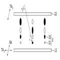
도 1은 본 발명의 제1 실시예에 따른 반사 투과형 액정 표시 장치의 단면도이다.
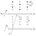
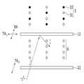
도 2 및 도 3는 본 발명의 제1 실시예에 따른 반사 투과형 액정 표시 장치의 반사 모드의 구동 원리를 나타낸 도면이다.
도 4 및 도 5는 본 발명의 제1 실시예에 따른 반사 투과형 액정 표시 장치의 투과 모드의 구동 원리를 나타낸 도면이다.
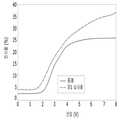
도 6은 본 발명의 제1 실시예에 따른 반사 투과형 액정 표시 장치의 구동 전압에 따른 투과율을 종래 기술에 따른 액정 표시 장치와 비교하여 나타낸 그래프이다.
도 7은 본 발명의 제1 실시예에 따른 반사 투과형 액정 표시 장치의 구동 전압에 따른 반사율을 종래 기술에 따른 액정 표시 장치와 비교하여 나타낸 그래프이다.
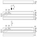
도 8은 본 발명의 제2 실시예에 따른 반사 투과형 액정 표시 장치의 단면도이다.
도 9 및 도 10은 본 발명의 제2 실시예에 따른 반사 투과형 액정 표시 장치의 반사 모드의 구동 원리를 나타낸 도면이다.
도 11 및 도 12는 본 발명의 제2 실시예에 따른 반사 투과형 액정 표시 장치의 투과 모드의 구동 원리를 나타낸 도면이다.
도 13은 본 발명의 제3 실시예에 따른 반사 투과형 액정 표시 장치의 단면도이다.
도 14 및 도 15는 본 발명의 제3 실시예에 따른 반사 투과형 액정 표시 장치의 반사 모드의 구동 원리를 나타낸 도면이다.
도 16 및 도 17은 본 발명의 제3 실시예에 따른 반사 투과형 액정 표시 장치의 투과 모드의 구동 원리를 나타낸 도면이다.
도 18은 본 발명의 제4 실시예에 따른 반사 투과형 액정 표시 장치의 단면도이다.
도 19 및 도 20은 본 발명의 제4 실시예에 따른 반사 투과형 액정 표시 장치의 반사 모드의 구동 원리를 나타낸 도면이다.
도 21 및 도 22는 본 발명의 제4 실시예에 따른 반사 투과형 액정 표시 장치의 투과 모드의 구동 원리를 나타낸 도면이다.
도 23은 본 발명의 제5 실시예에 따른 반사 투과형 액정 표시 장치의 단면도이다.
도 24 및 도 25는 본 발명의 제5 실시예에 따른 반사 투과형 액정 표시 장치의 반사 모드의 구동 원리를 나타낸 도면이다.
도 26 및 도 27는 본 발명의 제5 실시예에 따른 반사 투과형 액정 표시 장치의 투과 모드의 구동 원리를 나타낸 도면이다.1 is a cross-sectional view of a transmissive transmissive liquid crystal display device according to a first embodiment of the present invention.
FIG. 2 and FIG. 3 are views showing a driving principle of a reflective mode of a reflective transmissive liquid crystal display device according to a first embodiment of the present invention.
4 and 5 are views showing the principle of driving the transmission mode of the transflective liquid crystal display device according to the first embodiment of the present invention.
6 is a graph showing a transmittance according to a driving voltage of a reflective transmissive liquid crystal display device according to a first embodiment of the present invention, in comparison with a liquid crystal display device according to the related art.
FIG. 7 is a graph showing a reflectance according to a driving voltage of a transflective liquid crystal display device according to a first embodiment of the present invention, in comparison with a conventional liquid crystal display device.
8 is a cross-sectional view of a transflective liquid crystal display device according to a second embodiment of the present invention.
9 and 10 are views showing a driving principle of a reflective mode of a reflective transmissive liquid crystal display device according to a second embodiment of the present invention.
11 and 12 are views showing a principle of driving the transmissive mode of the transflective liquid crystal display device according to the second embodiment of the present invention.
13 is a cross-sectional view of a reflective transmissive liquid crystal display device according to a third embodiment of the present invention.
FIG. 14 and FIG. 15 are views showing the principle of driving the reflection mode of the reflective transmission type liquid crystal display device according to the third embodiment of the present invention.
16 and 17 are views showing the principle of driving the transmission mode of the transflective liquid crystal display device according to the third embodiment of the present invention.
18 is a cross-sectional view of a reflective transmissive liquid crystal display device according to a fourth embodiment of the present invention.
19 and 20 are views showing a driving principle of a reflective mode of a reflective transmissive liquid crystal display device according to a fourth embodiment of the present invention.
FIGS. 21 and 22 are views showing a principle of driving the transmissive mode of the transflective liquid crystal display device according to the fourth embodiment of the present invention.
23 is a cross-sectional view of a transflective liquid crystal display device according to a fifth embodiment of the present invention.
FIG. 24 and FIG. 25 are views showing the principle of driving the reflection mode of the transflective type liquid crystal display device according to the fifth embodiment of the present invention.
FIG. 26 and FIG. 27 are views showing the principle of driving the transmission mode of the transflective type liquid crystal display device according to the fifth embodiment of the present invention.
이하에서 첨부한 도면을 참고로 하여 본 발명의 실시예에 대하여 본 발명이 속하는 기술 분야에서 통상의 지식을 가진 자가 용이하게 실시할 수 있도록 상세히 설명한다. 그러나 본 발명은 여러 가지 상이한 형태로 구현될 수 있으며 여기에서 설명하는 실시예에 한정되지 않는다.Hereinafter, exemplary embodiments of the present invention will be described in detail with reference to the accompanying drawings, which will be readily apparent to those skilled in the art to which the present invention pertains. The present invention may, however, be embodied in many different forms and should not be construed as limited to the embodiments set forth herein.
도면에서 여러 층 및 영역을 명확하게 표현하기 위하여 두께를 확대하여 나타내었다. 명세서 전체를 통하여 유사한 부분에 대해서는 동일한 도면 부호를 붙였다. 층, 막, 영역, 판 등의 부분이 다른 부분 "위에" 있다고 할 때, 이는 다른 부분 "바로 위에" 있는 경우뿐 아니라 그 중간에 또 다른 부분이 있는 경우도 포함한다. 반대로 어떤 부분이 다른 부분 "바로 위에" 있다고 할 때에는 중간에 다른 부분이 없는 것을 뜻한다.
In the drawings, the thickness is enlarged to clearly represent the layers and regions. Like parts are designated with like reference numerals throughout the specification. It will be understood that when an element such as a layer, film, region, plate, or the like is referred to as being "on" another portion, it includes not only the element directly over another element, Conversely, when a part is "directly over" another part, it means that there is no other part in the middle.
먼저, 첨부된 도면을 참조하여 본 발명의 제1 실시예에 따른 반사 투과형 액정 표시 장치에 대해 설명하면 다음과 같다.First, a reflective transmissive liquid crystal display device according to a first embodiment of the present invention will be described with reference to the accompanying drawings.
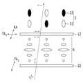
도 1은 본 발명의 제1 실시예에 따른 반사 투과형 액정 표시 장치의 단면도이다.1 is a cross-sectional view of a transmissive transmissive liquid crystal display device according to a first embodiment of the present invention.
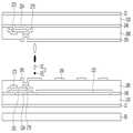
본 발명의 제1 실시예에 따른 반사 투과형 액정 표시 장치는 서로 대향하는 제1 기판(110) 및 제2 기판(210), 제1 기판(110)과 제2 기판(210) 사이에 형성되는 액정층(3)을 포함하는 액정 표시 패널을 포함한다.The liquid crystal display device according to the first embodiment of the present invention includes a
제1 기판(110) 위에는 도시는 생략하였으나, 서로 교차하여 복수의 화소를 정의하는 제1 게이트선 및 제1 데이터선, 이들에 연결되는 제1 박막 트랜지스터가 형성된다. 제1 박막 트랜지스터는 제1 기판(110) 위에 형성되는 제1 게이트 전극(124), 제1 게이트 전극(124) 위에 형성되는 제1 게이트 절연막(140), 제1 게이트 절연막(140) 위에 형성되는 제1 반도체층(151), 제1 반도체층(151) 위에 서로 이격되어 형성되는 제1 소스 전극(173) 및 제1 드레인 전극(175)을 포함한다.Although not shown on the
제1 소스 전극(173) 및 제1 드레인 전극(175) 위에는 제1 보호막(180)이 형성되고, 제1 보호막(180) 위의 화소 내에 제1 화소 전극(191)이 형성된다. 제1 화소 전극(191) 아래의 화소 내에는 공통 전극(132)이 형성된다. 제1 화소 전극(191)은 복수의 막대 모양이 연결된 형상으로 형성되어, 제1 화소 전극(191)과 공통 전극(132) 사이에서는 수평 전계가 형성될 수 있다.A
제2 기판(210) 위에는 도시는 생략하였으나, 서로 교차하여 복수의 화소를 정의하는 제2 게이트선 및 제2 데이터선, 이들에 연결되는 제2 박막 트랜지스터가 형성된다. 제2 박막 트랜지스터는 제2 기판(210) 위에 형성되는 제2 게이트 전극(224), 제2 게이트 전극(224) 위에 형성되는 제2 게이트 절연막(240), 제2 게이트 절연막(240) 위에 형성되는 제2 반도체층(251), 제2 반도체층(251) 위에 서로 이격되어 형성되는 제2 소스 전극(273) 및 제2 드레인 전극(275)을 포함한다.Although not shown on the
제2 소스 전극(273) 및 제2 드레인 전극(275) 위에는 제2 보호막(280)이 형성되고, 제2 보호막(280) 위의 화소 내에 제2 화소 전극(291)이 형성된다. 제2 화소 전극(291)과 공통 전극(132) 사이에서는 수직 전계가 형성될 수 있다.A
액정층(3)은 복수의 액정 분자(31) 및 복수의 이색성 염료(33)가 혼합되어 이루어진다. 이때, 액정층(3)은 제1 기판(110) 및 제2 기판(210)에 수평한 방향으로 배열되어 있다.The
액정 표시 패널의 외측에는 반사 편광판(12) 및 흡수 편광판(22)이 형성된다. 구체적으로, 반사 편광판(12)은 제1 기판(110)의 외측에 부착될 수 있고, 흡수 편광판(22)은 제2 기판의 외측에 부착될 수 있다.A
액정 표시 패널의 외측, 구체적으로 제1 기판(110)의 외측에는 백라이트 유닛(50)이 형성된다. 백라이트 유닛(50)은 광원의 배치 형태에 따라 직하형과 측광형으로 분류된다. 직하형은 액정 패널의 바로 아래에 설치된 램프가 광을 액정 표시 패널에 직접 조사하는 방식이고, 측광형은 도광판을 통해 광을 액정 표시 패널에 조사하는 방식이다. 본 발명의 백라이트 유닛(50)은 두 가지 방식 중 어느 것을 적용해도 무방하다. 백라이트 유닛(50)은 액정 표시 패널의 내측으로 광을 공급하며, 공급된 광은 액정 표시 패널의 외측, 구체적으로 제2 기판(210)의 외측으로 나와 화면을 표시한다.A
이어, 본 발명의 제1 실시예에 따른 반사 투과형 액정 표시 장치의 반사 모드와 투과 모드에서 각각 블랙 계조와 화이트 계조를 나타내는 원리에 대해 설명한다.Next, the principle of representing the black gradation and the white gradation in the reflection mode and the transmission mode, respectively, of the transflective liquid crystal display device according to the first embodiment of the present invention will be described.
도 2 및 도 3는 본 발명의 제1 실시예에 따른 반사 투과형 액정 표시 장치의 반사 모드의 구동 원리를 나타낸 도면이고, 도 4 및 도 5는 본 발명의 제1 실시예에 따른 반사 투과형 액정 표시 장치의 투과 모드의 구동 원리를 나타낸 도면이다.FIGS. 2 and 3 are views showing a driving principle of a reflective mode of a reflective transmissive liquid crystal display device according to a first embodiment of the present invention, and FIGS. 4 and 5 are views showing a reflective transmissive liquid crystal display according to a first embodiment of the present invention. And shows the principle of driving the transmission mode of the apparatus.
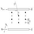
본 발명의 제1 실시예에 따른 반사 투과형 액정 표시 장치의 반사 편광판(12)은 제1 방향으로 진동하는 광을 반사시키는 반사축(RA) 및 제1 방향과 실질적으로 수직한 제2 방향으로 진동하는 광을 투과시키는 투과축(TA1)을 가진다. 또한, 흡수 편광판(22)은 제1 방향으로 진동하는 광을 투과시키는 투과축(TA2)를 가진다. 따라서, 반사 편광판(12)의 반사축(RA)은 흡수 편광판(22)의 투과축(TA2)과 평행하고, 반사 편광판(12)의 투과축(TA1)은 흡수 편광판(22)의 투과축(TA2)과 직교한다.The
액정층(3)은 반사 편광판(12)의 반사축(RA)과 평행한 방향으로 배열되어 있다. 따라서, 제1 방향으로 진동하는 광이 액정층(3) 내부로 들어오면 이색성 염료(33)에 의해 흡수된다.The
도 2를 참조하면, 반사 모드에서 외부로부터 제1 방향 및 제2 방향으로 진동하는 광이 입사되면, 흡수 편광판(22)의 투과축(TA2)과 나란한 제1 방향으로 진동하는 광만 흡수 편광판(22)을 통과하고, 제2 방향으로 진동하는 광은 흡수 편광판(22)에 흡수된다. 전계가 형성되어 있지 않은 상태에서 흡수 편광판(22)을 통과한 광은 위상 변화 없이 액정층(3)을 통과하게 되며, 제1 방향으로 진동하므로 액정층(3)의 내부로 입사하면 이색성 염료(33)에 의해 흡수된다. 따라서, 반사 모드에서 전계가 형성되지 않으면 블랙 계조를 표시할 수 있다.2, when light that vibrates from the outside in the first direction and the second direction is incident in the reflection mode, only the light oscillating in the first direction, which is parallel to the transmission axis TA2 of the
도 3을 참조하면, 반사 모드에서 외부로부터 제1 방향 및 제2 방향으로 진동하는 광이 입사되면, 흡수 편광판(22)의 투과축(TA2)과 나란한 제1 방향으로 진동하는 광만 흡수 편광판(22)을 통과하고, 제2 방향으로 진동하는 광은 흡수 편광판(22)에 흡수된다. 제2 화소 전극(도 1의 291)과 공통 전극(도 1의 132)에 전압이 인가되어 수직 전계가 형성되면, 액정층(3)은 반사 편광판(12) 및 흡수 편광판(22)과 수직한 방향으로 배열된다. 따라서, 흡수 편광판(22)을 통과한 광은 이색성 염료(33)에 의해 흡수되지 아니하고 반사 편광판(12)에 이를 수 있다. 반사 편광판(12)에 이르는 광은 반사 편광판(12)의 반사축(RA)과 나란한 제1 방향으로 진동하므로 반사 편광판(12)에 반사되어 흡수 편광판(22)에 이른다. 흡수 편광판(22)에 이르는 광은 흡수 편광판(22)의 투과축(TA2)과 나란한 제1 방향으로 진동하므로 액정 표시 패널의 외부로 표시된다. 따라서, 반사 모드에서 수직 전계가 형성되면 화이트 계조를 표시할 수 있다.3, when light that vibrates in the first direction and the second direction is incident from the outside in the reflection mode, only the light oscillating in the first direction parallel to the transmission axis TA2 of the
도 4를 참조하면, 투과 모드에서 백라이트 유닛(50)으로부터 제1 방향 및 제2 방향으로 진동하는 광이 입사되면, 반사 편광판(12)의 투과축(TA1)과 나란한 제2 방향으로 진동하는 광만 반사 편광판(12)을 통과하고, 제1 방향으로 진동하는 광은 반사 편광판(12)에 반사된다. 전계가 형성되어 있지 않은 상태에서 반사 편광판(12)을 통과한 광은 이색성 염료(33)에 의해 흡수되지 아니하고 흡수 편광판(22)에 이를 수 있다. 흡수 편광판(22)에 이르는 광은 흡수 편광판(22)의 투과축(TA2)과 수직한 제2 방향으로 진동하므로 흡수 편광판(22)에 흡수된다. 따라서, 투과 모드에서 전계가 형성되지 않으면 블랙 계조를 표시할 수 있다.Referring to FIG. 4, when light is incident from the
투과 모드에서도 외부로부터 광은 입사되고 따라서 반사 모드의 계조도 함께 표시된다. 본 발명의 투과 모드에서 블랙 계조를 표시할 때 반사 모드에서도 블랙 계조가 표시되므로 계조가 반전되는 것을 방지할 수 있다.Even in the transmissive mode, light is incident from the outside, and thus the gradation of the reflection mode is also displayed. When the black gradation is displayed in the transmissive mode of the present invention, the black gradation is displayed even in the reflective mode, so that the gradation can be prevented from being inverted.
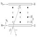
도 5를 참조하면, 투과 모드에서 백라이트 유닛(50)으로부터 제1 방향 및 제2 방향으로 진동하는 광이 입사되면, 반사 편광판(12)의 투과축(TA1)과 나란한 제2 방향으로 진동하는 광만 반사 편광판(12)을 통과하고, 제1 방향으로 진동하는 광은 반사 편광판(12)에 반사된다. 제1 화소 전극(도 1의 191)과 공통 전극(도 1의 132)에 전압이 인가되어 수평 전계가 형성되면 액정층(3)은 회전하게 되고, 반사 편광판(12)을 통과한 광은 액정층(3)을 통과할 때 위상이 90도 변한다. 따라서, 액정층(3)을 통과한 광은 이색성 염료(33)에 의해 흡수되지 아니하고 흡수 편광판(22)에 이를 수 있다. 흡수 편광판(22)에 이르는 광은 흡수 편광판(22)의 투과축(TA2)과 나란한 제1 방향으로 진동하므로 액정 표시 패널의 외부로 표시된다. 따라서, 투과 모드에서 수평 전계가 형성되면 화이트 계조를 표시할 수 있다.5, when light is incident from the
투과 모드의 화이트 계조를 표시할 때 반사 모드에서도 화이트 계조가 표시되므로 역시 계조가 반전되는 것을 방지할 수 있다.White gradation is displayed even in the reflection mode when the white gradation of the transmission mode is displayed, so that it is also possible to prevent the gradation from being inverted.
본 발명에서는 투과 모드의 블랙 계조를 표시할 때 반사 모드에서도 블랙 계조를 표시하게 되고, 투과 모드의 화이트 계조를 표시할 때 반사 모드에서도 화이트 계조를 표시하게 된다. 즉, 투과 모드의 블랙 계조를 표시할 때는 외부로부터 들어오는 광이 반사되지 않도록 하여 블랙 계조를 더욱 잘 나타낼 수 있고, 투과 모드의 화이트 계조를 표시할 때는 외부로부터 들어오는 광이 반사되도록 하여 화이트 계조를 더욱 잘 나타낼 수 있다. 이는 이색성 염료(33)를 반사 편광판(12)과 수직한 방향으로 배열시키면 외부로부터 입사된 광은 이색성 염료(33)에 흡수되지 않고 반사 편광판(12)에 이를 수 있는 반면에, 반사 편광판(12)의 반사축(RA)과 나란한 방향으로 배열시키면 광은 이색성 염료(33)에 흡수되어 반사 편광판(12)에 이르지 못해 외부로 반사될 수 없는 특성을 이용한 것이다.
In the present invention, the black gradation is displayed in the reflective mode when the black gradation of the transmission mode is displayed, and the white gradation is displayed even in the reflective mode when the white gradation of the transmission mode is displayed. That is, when the black gradation of the transmission mode is displayed, the light coming from the outside is not reflected, so that the black gradation can be represented more easily. When the white gradation of the transmission mode is displayed, It can be shown well. This is because when the
이어, 본 발명의 제1 실시예에 따른 반사 투과형 액정 표시 장치의 투과율과 반사율에 대해 설명한다.Next, transmittance and reflectance of the transflective liquid crystal display device according to the first embodiment of the present invention will be described.
도 6은 본 발명의 제1 실시예에 따른 반사 투과형 액정 표시 장치의 구동 전압에 따른 투과율을 종래 기술에 따른 액정 표시 장치와 비교하여 나타낸 그래프이고, 도 7은 본 발명의 제1 실시예에 따른 반사 투과형 액정 표시 장치의 구동 전압에 따른 반사율을 종래 기술에 따른 액정 표시 장치와 비교하여 나타낸 그래프이다.FIG. 6 is a graph illustrating a transmittance according to a driving voltage of a reflective transmissive liquid crystal display device according to a first embodiment of the present invention, in comparison with a conventional liquid crystal display device. FIG. And the reflectance according to the driving voltage of the transflective liquid crystal display device is compared with the liquid crystal display device according to the related art.
도 6에서 종래 1은 일반적인 투과형 액정 표시 장치를 의미하는 것으로, FFS(Fringe Field Switching) 모드의 액정 표시 장치를 이용하여 투과율을 측정하였으며, 종래 2는 종래의 두 개의 액정 표시 패널로 이루어진 반사 투과형 액정 표시 장치를 의미한다.In FIG. 6,
도 6을 참조하면, 본 발명의 제1 실시예에 의한 반사 투과형 액정 표시 장치는 일반적인 투과형 액정 표시 장치와 유사한 투과 특성을 나타내고, 종래의 두 개의 액정 표시 패널로 이루어진 반사 투과형 액정 표시 장치보다 더 높은 투과율을 가지는 것을 확인할 수 있다.Referring to FIG. 6, the reflective transmissive liquid crystal display device according to the first embodiment of the present invention exhibits transmission characteristics similar to those of a general transmissive liquid crystal display device, and is higher in transmissivity than a reflective transmissive liquid crystal display device comprising two conventional liquid crystal display panels. Transmittance can be confirmed.
도 7에서 종래는 종래의 두 개의 액정 표시 패널로 이루어진 반사 투과형 액정 표시 장치를 의미한다.In FIG. 7, the conventional liquid crystal display device is a transmissive liquid crystal display device comprising two conventional liquid crystal display panels.
도 7을 참조하면, 본 발명의 제1 실시에에 의한 반사 투과형 액정 표시 장치는 종래의 두 개의 액정 표시 패널로 이루어진 반사 투과형 액정 표시 장치보다 더 높은 반사율을 가지는 것을 확인할 수 있다. 또한, 블랙 계조에서의 반사율과 화이트 계조에서의 반사율의 차이가 더 커져서 대비비(contrast ratio)도 증가하는 것을 확인할 수 있다.
Referring to FIG. 7, it can be seen that the reflective transmissive liquid crystal display device according to the first embodiment of the present invention has a higher reflectance than the reflective transmissive liquid crystal display device comprising two conventional liquid crystal display panels. In addition, it can be seen that the difference between the reflectance in the black gradation and the reflectance in the white gradation becomes larger and the contrast ratio also increases.
다음으로, 첨부된 도면을 참조하여 본 발명의 제2 실시예에 따른 반사 투과형 액정 표시 장치에 대해 설명하면 다음과 같다.Next, a reflective transmissive liquid crystal display device according to a second embodiment of the present invention will be described with reference to the accompanying drawings.
도 8은 본 발명의 제2 실시예에 따른 반사 투과형 액정 표시 장치의 단면도이다.8 is a cross-sectional view of a transflective liquid crystal display device according to a second embodiment of the present invention.
본 발명의 제2 실시예에 따른 반사 투과형 액정 표시 장치는 제1 실시예에 따른 반사 투과형 액정 표시 장치와 동일한 부분이 상당하므로, 이에 대한 설명은 생략하고 차이점이 있는 부분에 대해서만 이하에서 설명한다.Since the reflective transmissive liquid crystal display device according to the second embodiment of the present invention is the same as the reflective transmissive liquid crystal display device according to the first embodiment, a description thereof will be omitted and only differences will be described below.
본 발명의 제2 실시예에 따른 반사 투과형 액정 표시 장치는 서로 대향하는 제1 기판(110) 및 제2 기판(210), 제1 기판(110)과 제2 기판(210) 사이에 형성되는 액정층(3)을 포함하는 액정 표시 패널을 포함한다는 점에서는 제1 실시예에 따른 반사 투과형 액정 표시 장치와 동일하다.The liquid crystal display device according to the second embodiment of the present invention includes a
그러나, 제1 실시예에서는 액정층(3)이 수평 방향으로 배열되어 있는 반면에, 제2 실시예에서는 액정층(3)이 제1 기판(110) 및 제2 기판(210)에 수직한 방향으로 배열되어 있다.However, in the first embodiment, the
그 외, 반사 편광판(12), 흡수 편광판(22), 백라이트 유닛(50)은 제1 실시예와 동일하게 형성된다.In addition, the
이어, 본 발명의 제2 실시예에 따른 반사 투과형 액정 표시 장치의 반사 모드와 투과 모드에서 각각 블랙 계조와 화이트 계조를 나타내는 원리에 대해 설명한다.Next, the principle of representing the black gradation and the white gradation in the reflection mode and the transmission mode of the transflective liquid crystal display device according to the second embodiment of the present invention will be described.
도 9 및 도 10은 본 발명의 제2 실시예에 따른 반사 투과형 액정 표시 장치의 반사 모드의 구동 원리를 나타낸 도면이고, 도 11 및 도 12는 본 발명의 제2 실시예에 따른 반사 투과형 액정 표시 장치의 투과 모드의 구동 원리를 나타낸 도면이다.FIGS. 9 and 10 are views showing a driving principle of a reflective mode of a reflective transmissive liquid crystal display device according to a second embodiment of the present invention. FIGS. 11 and 12 are views showing a reflective transmissive liquid crystal display device according to a second embodiment of the present invention. And shows the principle of driving the transmission mode of the apparatus.
본 발명의 제2 실시예에 따른 반사 투과형 액정 표시 장치의 반사 편광판(12)은 제1 방향으로 진동하는 광을 투과시키는 투과축(TA1) 및 제1 방향과 실질적으로 수직한 제2 방향으로 진동하는 광을 반사시키는 반사축(RA)을 가진다. 또한, 흡수 편광판(22)은 제2 방향으로 진동하는 광을 투과시키는 투과축(TA2)을 가진다. 따라서, 반사 편광판(12)의 반사축(RA)은 흡수 편광판(22)의 투과축(TA2)과 평행하고, 반사 편광판(12)의 투과축(TA1)은 흡수 편광판(22)의 투과축(TA2)과 직교한다.The
제2 실시예에 따른 반사 투과형 액정 표시 장치의 액정층(3)은 앞서 설명한 바와 같이 제1 실시예에 따른 반사 투과형 액정 표시 장치의 액정층(3)과 배열이 상이하며, 반사 편광판(12) 및 흡수 편광판(22)과 수직한 방향으로 배열되어 있다. 따라서, 제1 방향 및 제2 방향으로 진동하는 광이 액정층(3) 내부로 들어오더라도 이색성 염료(33)에 흡수되지 않는다.The
도 9를 참조하면, 반사 모드에서 외부로부터 제1 방향 및 제2 방향으로 진동하는 광이 입사되면, 흡수 편광판(22)의 투과축(TA2)과 나란한 제2 방향으로 진동하는 광만 흡수 편광판(22)을 통과하고, 제1 방향으로 진동하는 광은 흡수 편광판(22)에 흡수된다. 전계가 형성되어 있지 않은 상태에서 액정층(3)은 흡수 편광판(22)에 수직한 방향으로 배열되어 있으며, 흡수 편광판(22)을 통과한 광은 위상 변화 없이 액정층(3)을 통과하게 되므로 이색성 염료(33)에 의해 흡수되지 아니하고 반사 편광판(12)에 이를 수 있다. 반사 편광판(12)에 이르는 광은 반사 편광판(12)의 반사축(RA)과 나란한 제2 방향으로 진동하므로 반사 편광판(12)에 반사되어 흡수 편광판(22)에 이른다. 흡수 편광판(22)에 이르는 광은 흡수 편광판(22)의 투과축(TA2)과 나란한 제2 방향으로 진동하므로 액정 표시 패널의 외부로 표시된다. 따라서, 반사 모드에서 전계가 형성되지 않으면 화이트 계조를 표시할 수 있다.9, when light that vibrates in the first direction and the second direction from the outside is incident in the reflection mode, only the light oscillating in the second direction parallel to the transmission axis TA2 of the
도 10을 참조하면, 반사 모드에서 외부로부터 제1 방향 및 제2 방향으로 진동하는 광이 입사되면, 흡수 편광판(22)의 투과축(TA2)과 나란한 제2 방향으로 진동하는 광만 흡수 편광판(22)을 통과하고, 제1 방향으로 진동하는 광은 흡수 편광판(22)에 흡수된다. 제2 화소 전극(도 1의 291)과 공통 전극(도 1의 132)에 전압이 인가되어 수직 전계가 형성되면, 액정층(3)은 반사 편광판(12)의 반사축(RA)과 평행한 방향으로 배열된다. 흡수 편광판(22)을 통과한 광은 위상 변화 없이 액정층(3)을 통과하게 되며, 제2 방향으로 진동하므로 액정층(3)의 내부로 입사하면 이색성 염료(33)에 의해 흡수된다. 따라서, 반사 모드에서 수직 전계가 형성되면 블랙 계조를 표시할 수 있다.10, when light that vibrates in the first direction and the second direction from outside is incident in the reflection mode, only the light that vibrates in the second direction parallel to the transmission axis TA2 of the
도 11을 참조하면, 투과 모드에서 백라이트 유닛(50)으로부터 제1 방향 및 제2 방향으로 진동하는 광이 입사되면, 반사 편광판(12)의 투과축(TA1)과 나란한 제1 방향으로 진동하는 광만 반사 편광판(12)을 통과하고, 제2 방향으로 진동하는 광은 반사 편광판(12)에 반사된다. 제1 화소 전극(도 1의 191)과 공통 전극(도 1의 132)에 전압이 인가되어 수평 전계가 형성되고, 동시에 제2 화소 전극(도 1의 291)에도 전압이 인가되어 제2 화소 전극(도 1의 291)과 공통 전극(도 1의 132) 사이에 수직 전계가 형성되면, 액정층(3)은 회전하게 되고, 반사 편광판(12)을 통과한 광은 액정층(3)을 통과할 때 위상이 90도 변한다. 따라서, 액정층(3)을 통과한 광은 이색성 염료(33)에 의해 흡수되지 아니하고 흡수 편광판(22)에 이를 수 있다. 흡수 편광판(22)에 이르는 광은 흡수 편광판(22)의 투과축(TA2)과 나란한 제2 방향으로 진동하므로 액정 표시 패널의 외부로 표시된다. 따라서, 투과 모드에서 수평 전계 및 수직 전계가 형성되면 화이트 계조를 표시할 수 있다.11, when light vibrating in the first direction and the second direction is incident from the
도 12를 참조하면, 투과 모드에서 백라이트 유닛(50)으로부터 제1 방향 및 제2 방향으로 진동하는 광이 입사되면, 반사 편광판(12)의 투과축(TA1)과 나란한 제1 방향으로 진동하는 광만 반사 편광판(12)을 통과하고, 제2 방향으로 진동하는 광은 반사 편광판(12)에 반사된다. 제2 화소 전극(도 1의 291)과 공통 전극(도 1의 132)에 전압이 인가되어 수직 전계가 형성되면, 액정층(3)은 반사 편광판(12)의 반사축(RA)과 평행한 방향으로 배열된다. 반사 편광판(12)을 통과한 광은 위상 변화 없이 액정층(3)을 통과하게 되며, 흡수 편광판(22)의 투과축(TA2)과 수직한 제2 방향으로 진동하므로 흡수 편광판(22)에 흡수된다. 따라서, 투과 모드에서 수직 전계가 형성되면 블랙 계조를 표시할 수 있다.12, when light that vibrates in the first direction and the second direction is incident from the
투과 모드의 블랙 계조를 할 때 반사 모드에서도 블랙 계조가 표시되므로 계조가 반전되는 것을 방지할 수 있다.
The black gradation is displayed even in the reflection mode when the black gradation of the transmission mode is performed, so that the gradation can be prevented from being inverted.
다음으로, 첨부된 도면을 참조하여 본 발명의 제3 실시예에 따른 반사 투과형 액정 표시 장치에 대해 설명하면 다음과 같다.Next, a reflective transmissive liquid crystal display device according to a third embodiment of the present invention will be described with reference to the accompanying drawings.
도 13은 본 발명의 제3 실시예에 따른 반사 투과형 액정 표시 장치의 단면도이다.13 is a cross-sectional view of a reflective transmissive liquid crystal display device according to a third embodiment of the present invention.
본 발명의 제3 실시예에 따른 반사 투과형 액정 표시 장치는 제1 실시예에 따른 반사 투과형 액정 표시 장치와 동일한 부분이 상당하므로, 이에 대한 설명은 생략하고 차이점이 있는 부분에 대해서만 이하에서 설명한다.Since the reflective transmissive liquid crystal display device according to the third embodiment of the present invention is the same as the reflective transmissive liquid crystal display device according to the first embodiment, a description thereof will be omitted and only differences will be described below.
본 발명의 제3 실시예에 따른 반사 투과형 액정 표시 장치는 서로 대향하는 제1 기판(110) 및 제2 기판(210), 제1 기판(110)과 제2 기판(210) 사이에 형성되는 액정층(3)을 포함하는 액정 표시 패널을 포함한다는 점에서는 제1 실시예에 따른 반사 투과형 액정 표시 장치와 동일하다.The liquid crystal display device according to the third embodiment of the present invention includes a
그러나, 제1 실시예에서는 액정층(3)이 수평 방향으로 배열되어 있는 반면에, 제3 실시예에서는 액정층(3)이 제1 기판(110)에 인접한 부분에서는 제1 기판(110)에 평행한 방향으로 배열되고, 제2 기판(210)에 인접한 부분에서는 제2 기판(210)에 수직한 방향으로 배열되어 있다.However, in the first embodiment, the
그 외, 반사 편광판(12), 흡수 편광판(22), 백라이트 유닛(50)은 제1 실시예와 동일하게 형성된다.In addition, the
이어, 본 발명의 제3 실시예에 따른 반사 투과형 액정 표시 장치의 반사 모드와 투과 모드에서 각각 블랙 계조와 화이트 계조를 나타내는 원리에 대해 설명한다.Next, the principle of representing the black gradation and the white gradation in the reflection mode and the transmission mode of the reflective transmissive liquid crystal display device according to the third embodiment of the present invention will be described.
도 14 및 도 15는 본 발명의 제3 실시예에 따른 반사 투과형 액정 표시 장치의 반사 모드의 구동 원리를 나타낸 도면이고, 도 16 및 도 17은 본 발명의 제3 실시예에 따른 반사 투과형 액정 표시 장치의 투과 모드의 구동 원리를 나타낸 도면이다.FIGS. 14 and 15 are views showing a driving principle of a reflective mode of a reflective transmissive liquid crystal display device according to a third embodiment of the present invention, and FIGS. 16 and 17 are views showing a reflective transmissive liquid crystal display according to a third embodiment of the present invention. And shows the principle of driving the transmission mode of the apparatus.
본 발명의 제3 실시예에 따른 반사 투과형 액정 표시 장치의 반사 편광판(12)은 제1 방향으로 진동하는 광을 반사시키는 반사축(RA) 및 제1 방향과 실질적으로 수직한 제2 방향으로 진동하는 광을 투과시키는 투과축(TA1)을 가진다. 또한, 흡수 편광판(22)은 제1 방향으로 진동하는 광을 투과시키는 투과축(TA2)를 가진다. 따라서, 반사 편광판(12)의 반사축(RA)은 흡수 편광판(22)의 투과축(TA2)과 평행하고, 반사 편광판(12)의 투과축(TA1)은 흡수 편광판(22)의 투과축(TA2)과 직교한다.The
액정층(3)은 제1 기판(도 13의 110)에 인접한 부분에서는 반사 편광판(12)의 반사축(RA)과 평행한 방향으로 배열되어 있다. 따라서, 제1 방향으로 진동하는 광이 액정층(3) 내부로 들어오면 이색성 염료(33)에 의해 흡수된다. 또한, 액정층(3)은 제2 기판(도 13의 210)에 인접한 부분에서는 반사 편광판(12)에 수직한 방향으로 배열되어 있다.The
도 14를 참조하면, 반사 모드에서 외부로부터 제1 방향 및 제2 방향으로 진동하는 광이 입사되면, 흡수 편광판(22)의 투과축과 나란한 제1 방향으로 진동하는 광만 흡수 편광판(22)을 통과하고, 제2 방향으로 진동하는 광은 흡수 편광판(22)에 흡수된다. 전계가 형성되어 있지 않은 상태에서 흡수 편광판(22)을 통과한 광은 위상 변화 없이 액정층(3)을 통과하게 되며, 제1 방향으로 진동하므로 액정층(3)의 내부로 입사하면 이색성 염료(33)에 의해 흡수된다. 따라서, 반사 모드에서 전계가 형성되지 않으면 블랙 계조를 표시할 수 있다.14, when light that vibrates from the outside in the first direction and the second direction is incident in the reflection mode, only the light that vibrates in the first direction parallel to the transmission axis of the
도 15를 참조하면, 반사 모드에서 외부로부터 제1 방향 및 제2 방향으로 진동하는 광이 입사되면, 흡수 편광판(22)의 투과축(TA2)과 나란한 제1 방향으로 진동하는 광만 흡수 편광판(22)을 통과하고, 제2 방향으로 진동하는 광은 흡수 편광판(22)에 흡수된다. 제2 화소 전극(도 1의 291)과 공통 전극(도 1의 132)에 전압이 인가되어 수직 전계가 형성되면, 액정층(3)은 반사 편광판(12) 및 흡수 편광판(22)과 수직한 방향으로 배열된다. 따라서, 흡수 편광판(22)을 통과한 광은 이색성 염료(33)에 의해 흡수되지 아니하고 반사 편광판(12)에 이를 수 있다. 반사 편광판(12)에 이르는 광은 반사 편광판(12)의 반사축(RA)과 나란한 제1 방향으로 진동하므로 반사 편광판(12)에 반사되어 흡수 편광판(22)에 이른다. 흡수 편광판(22)에 이르는 광은 흡수 편광판(22)의 투과축(TA2)과 나란한 제1 방향으로 진동하므로 액정 표시 패널의 외부로 표시된다. 따라서, 반사 모드에서 수직 전계가 형성되면 화이트 계조를 표시할 수 있다.15, when light that vibrates in the first direction and the second direction is incident from the outside in the reflection mode, only the light oscillating in the first direction parallel to the transmission axis TA2 of the
도 16을 참조하면, 투과 모드에서 백라이트 유닛(50)으로부터 제1 방향 및 제2 방향으로 진동하는 광이 입사되면, 반사 편광판(12)의 투과축(TA1)과 나란한 제2 방향으로 진동하는 광만 반사 편광판(12)을 통과하고, 제1 방향으로 진동하는 광은 반사 편광판(12)에 반사된다. 전계가 형성되어 있지 않은 상태에서 반사 편광판(12)을 통과한 광은 이색성 염료(33)에 의해 흡수되지 아니하고 흡수 편광판(22)에 이를 수 있다. 흡수 편광판(22)에 이르는 광은 흡수 편광판(22)의 투과축(TA2)과 수직한 제2 방향으로 진동하므로 흡수 편광판(22)에 흡수된다. 따라서, 투과 모드에서 전계가 형성되지 않으면 블랙 계조를 표시할 수 있다.Referring to FIG. 16, when light is incident from the
투과 모드에서도 외부로부터 광은 입사되고 따라서 반사 모드의 계조도 함께 표시된다. 본 발명의 투과 모드에서 블랙 계조를 표시할 때 반사 모드에서도 블랙 계조가 표시되므로 계조가 반전되는 것을 방지할 수 있다.Even in the transmissive mode, light is incident from the outside, and thus the gradation of the reflection mode is also displayed. When the black gradation is displayed in the transmissive mode of the present invention, the black gradation is displayed even in the reflective mode, so that the gradation can be prevented from being inverted.
도 17을 참조하면, 투과 모드에서 백라이트 유닛(50)으로부터 제1 방향 및 제2 방향으로 진동하는 광이 입사되면, 반사 편광판(12)의 투과축(TA1)과 나란한 제2 방향으로 진동하는 광만 반사 편광판(12)을 통과하고, 제1 방향으로 진동하는 광은 반사 편광판(12)에 반사된다. 제1 화소 전극(도 1의 191)과 공통 전극(도 1의 132)에 전압이 인가되어 수평 전계가 형성되면 액정층(3)은 회전하게 되고, 반사 편광판(12)을 통과한 광은 액정층(3)을 통과할 때 위상이 90도 변한다. 따라서, 액정층(3)을 통과한 광은 이색성 염료(33)에 의해 흡수되지 아니하고 흡수 편광판(22)에 이를 수 있다. 흡수 편광판(22)에 이르는 광은 흡수 편광판(22)의 투과축(TA2)과 나란한 제1 방향으로 진동하므로 액정 표시 패널의 외부로 표시된다. 따라서, 투과 모드에서 수평 전계가 형성되면 화이트 계조를 표시할 수 있다.Referring to FIG. 17, when light that vibrates in the first direction and the second direction is incident from the
투과 모드의 화이트 계조를 표시할 때 반사 모드에서도 화이트 계조가 표시되므로 역시 계조가 반전되는 것을 방지할 수 있다.
White gradation is displayed even in the reflection mode when the white gradation of the transmission mode is displayed, so that it is also possible to prevent the gradation from being inverted.
다음으로, 첨부된 도면을 참조하여 본 발명의 제4 실시예에 따른 반사 투과형 액정 표시 장치에 대해 설명하면 다음과 같다.Next, a reflective transmissive liquid crystal display device according to a fourth embodiment of the present invention will be described with reference to the accompanying drawings.
도 18은 본 발명의 제4 실시예에 따른 반사 투과형 액정 표시 장치의 단면도이다.18 is a cross-sectional view of a reflective transmissive liquid crystal display device according to a fourth embodiment of the present invention.
본 발명의 제4 실시예에 따른 반사 투과형 액정 표시 장치는 서로 대향하는 제1 기판(110) 및 제2 기판(210), 제1 기판(110)과 제2 기판(210) 사이에 형성되는 액정층(3)을 포함하는 액정 표시 패널을 포함한다. 또한, 서로 대향하는 제3 기판(310) 및 제4 기판(410), 제3 기판(310)과 제4 기판(410) 사이에 형성되는 보조 액정층(6)을 포함하는 보조 액정 표시 패널을 더 포함한다.The liquid crystal display device according to the fourth embodiment of the present invention includes a
제1 기판(110) 위에는 도시는 생략하였으나, 서로 교차하여 복수의 화소를 정의하는 제1 게이트선 및 제1 데이터선, 이들에 연결되는 제1 박막 트랜지스터가 형성된다. 제1 박막 트랜지스터는 제1 기판(110) 위에 형성되는 제1 게이트 전극(124), 제1 게이트 전극(124) 위에 형성되는 제1 게이트 절연막(140), 제1 게이트 절연막(140) 위에 형성되는 제1 반도체층(151), 제1 반도체층(151) 위에 서로 이격되어 형성되는 제1 소스 전극(173) 및 제1 드레인 전극(175)을 포함한다. 제1 소스 전극(173) 및 제1 드레인 전극(175) 위에는 제1 보호막(180)이 형성되고, 제1 보호막(180) 위의 화소 내에 제1 화소 전극(191)이 형성된다.Although not shown on the
제2 기판(210) 위에는 제1 공통 전극(270)이 형성된다. 제1 기판(110)과 제2 기판(210)은 서로 대향하도록 형성되어 있으므로, 제1 화소 전극(191)과 제1 공통 전극(270)에 전압이 인가되면 제1 화소 전극(191)과 제1 공통 전극(270) 사이에 수직 전계가 형성될 수 있다.A first
액정층(3)은 복수의 액정 분자(31) 및 복수의 이색성 염료(33)가 혼합되어 이루어진다. 이때, 액정층(3)은 제1 기판(110) 및 제2 기판(210)에 수직한 방향으로 배열되어 있다.The
제3 기판(310) 위에는 도시는 생략하였으나, 서로 교차하여 복수의 화소를 정의하는 제2 게이트선 및 제2 데이터선, 이들에 연결되는 제2 박막 트랜지스터가 형성된다. 제2 박막 트랜지스터는 제3 기판(310) 위에 형성되는 제2 게이트 전극(224), 제2 게이트 전극(224) 위에 형성되는 제2 게이트 절연막(240), 제2 게이트 절연막(240) 위에 형성되는 제2 반도체층(251), 제2 반도체층(251) 위에 서로 이격되어 형성되는 제2 소스 전극(273) 및 제2 드레인 전극(275)을 포함한다. 제2 소스 전극(273) 및 제2 드레인 전극(275) 위에는 제2 보호막(280)이 형성되고, 제2 보호막(280) 위의 화소 내에 제2 화소 전극(291)이 형성된다.Although not shown on the
제4 기판(410) 위에는 제2 공통 전극(470)이 형성된다. 제3 기판(310)과 제4 기판(410)은 서로 대향하도록 형성되어 있으므로, 제2 화소 전극(291)과 제2 공통 전극(470)에 전압이 인가되면 제2 화소 전극(291)과 제2 공통 전극(470) 사이에 수직 전계가 형성될 수 있다.A second
보조 액정층(6)은 제3 기판(310) 및 제4 기판(410)에 수평한 방향으로 배열되어 있다.The auxiliary
액정 표시 패널의 외측에는 반사 편광판(12) 및 흡수 편광판(22)이 형성된다. 구체적으로, 반사 편광판(12)은 액정 표시 패널과 보조 액정 표시 패널 사이에 즉, 제1 기판(110)과 제4 기판(410)의 사이에 위치하도록 부착될 수 있다. 또한, 흡수 편광판(22)은 보조 액정 표시 패널의 외측에 즉, 제3 기판(310)의 외측에 부착될 수 있다.A
보조 액정 표시 패널의 외측, 구체적으로 제3 기판(310)의 외측에는 백라이트 유닛(50)이 형성된다. 이때, 흡수 편광판(22)은 액정 표시 패널의 제3 기판(310)과 백라이트 유닛(50)의 사이에 위치하게 된다. 백라이트 유닛(50)은 보조 액정 표시 패널의 내측으로 광을 공급하며, 공급된 광은 보조 액정 표시 패널의 외측, 구체적으로 제4 기판(410)의 외측으로 나와 액정 표시 패널의 내측, 구체적으로 제1 기판(110)의 내측으로 들어간다. 액정 표시 패널의 내측으로 공급된 광은 액정 표시 패널의 외측, 구체적으로 제2 기판(210)의 외측으로 나와 화면을 표시한다.A
이어, 본 발명의 제4 실시예에 따른 반사 투과형 액정 표시 장치의 반사 모드와 투과 모드에서 각각 블랙 계조와 화이트 계조를 나타내는 원리에 대해 설명한다.Next, the principle of representing the black gradation and the white gradation in the reflection mode and the transmission mode of the reflective transmissive liquid crystal display device according to the fourth embodiment of the present invention will be described.
도 19 및 도 20은 본 발명의 제4 실시예에 따른 반사 투과형 액정 표시 장치의 반사 모드의 구동 원리를 나타낸 도면이며, 도 21 및 도 22는 본 발명의 제4 실시예에 따른 반사 투과형 액정 표시 장치의 투과 모드의 구동 원리를 나타낸 도면이다.FIGS. 19 and 20 are views showing a driving principle of a reflective mode of a transflective type liquid crystal display device according to a fourth embodiment of the present invention. FIGS. 21 and 22 are views showing a reflective transmissive liquid crystal display device according to a fourth embodiment of the present invention. And shows the principle of driving the transmission mode of the apparatus.
본 발명의 제4 실시예에 따른 반사 투과형 액정 표시 장치의 반사 편광판(12)은 제1 방향으로 진동하는 광을 반사시키는 반사축(RA) 및 제1 방향과 실질적으로 수직한 제2 방향으로 진동하는 광을 투과시키는 투과축(TA1)을 가진다. 또한, 흡수 편광판(22)은 제1 방향으로 진동하는 광을 투과시키는 투과축(TA2)를 가진다. 따라서, 반사 편광판(12)의 반사축(RA)은 흡수 편광판(22)의 투과축(TA2)과 평행하고, 반사 편광판(12)의 투과축(TA1)은 흡수 편광판(22)의 투과축(TA2)과 직교한다.The
액정 표시 패널의 액정층(3)은 반사 편광판(12)에 수직한 방향으로 배열되어 있고, 보조 액정 표시 패널의 보조 액정층(6)은 반사 편광판(12)과 평행한 방향으로 배열되어 있다.The
도 19를 참조하면, 반사 모드에서 외부로부터 제1 방향 및 제2 방향으로 진동하는 광이 입사되면, 액정 표시 패널과 보조 액정 표시 패널 모두에 전계가 형성되어 있지 않은 상태에서 액정 표시 패널의 내부로 입사한 광은 위상 변화 없이 액정층(3)을 통과하게 된다. 이때, 액정층(3)은 반사 편광판(12)에 수직한 방향으로 배열되어 있으므로, 제1 방향 및 제2 방향으로 진동하는 광이 모두 이색성 염료(33)에 의해 흡수되지 아니하고 반사 편광판(12)에 이를 수 있다. 반사 편광판(12)에 이르는 광 중 반사 편광판(12)의 투과축(TA1)과 나란한 제2 방향으로 진동하는 광은 반사 편광판(12)을 통과하여 흡수 편광판(22)에 이르고, 흡수 편광판(22)의 투과축(TA2)에 수직한 방향으로 진동하므로 흡수 편광판(22)에 흡수된다. 반사 편광판(12)에 이르는 광 중 반사 편광판(12)의 반사축(RA)과 나란한 제1 방향으로 진동하는 광은 반사 편광판(12)에 반사되어 액정 표시 패널의 외부로 표시된다. 따라서, 반사 모드에서 액정 표시 패널과 보조 액정 표시 패널에 전계가 형성되지 않으면 화이트 계조를 표시할 수 있다.19, when light that vibrates from the outside in the first direction and the second direction is incident in the reflection mode, the liquid crystal display panel and the auxiliary liquid crystal display panel are moved to the inside of the liquid crystal display panel The incident light passes through the
도 20을 참조하면, 반사 모드에서 외부로부터 제1 방향 및 제2 방향으로 진동하는 광이 입사되고, 액정 표시 패널의 제1 화소 전극(도 18의 191)과 제1 공통 전극(도 18의 270)에 전압이 인가되어 수직 전계가 형성되면 액정층(3)은 반사 편광판(12)의 반사축(RA)과 평행한 방향으로 배열되어, 이색성 염료(33)와 나란한 제1 방향으로 진동하는 광은 이색성 염료(33)에 의해 흡수되고, 반사 편광판(12)의 투과축(TA1)과 나란한 제2 방향으로 진동하는 광은 반사 편광판(12)을 통과하게 된다. 보조 액정 표시 패널에는 전계가 형성되어 있지 않은 상태에서 반사 편광판(12)을 통과한 광은 위상 변화 없이 흡수 편광판(22)에 이르게 되고, 흡수 편광판(22)의 투과축(TA2)에 수직한 방향으로 진동하므로 흡수 편광판(22)에 흡수된다. 따라서, 반사 모드에서 액정 표시 패널에 수직 전계가 형성되면 블랙 계조를 표시할 수 있다.Referring to FIG. 20, light that vibrates in the first direction and the second direction from outside is incident in the reflection mode, and the first pixel electrode (191 in FIG. 18) and the first common electrode The
도 21을 참조하면, 투과 모드에서 백라이트 유닛(50)으로부터 제1 방향 및 제2 방향으로 진동하는 광이 입사되면, 흡수 편광판(22)의 투과축(TA2)과 나란한 제1 방향으로 진동하는 광만 흡수 편광판(22)을 통과하고, 제2 방향으로 진동하는 광은 흡수 편광판(22)에 흡수된다. 보조 액정 표시 패널에 전계가 형성되어 있지 않은 상태에서 흡수 편광판(22)을 통과한 광은 위상 변화 없이 보조 액정층(6)을 통과하여 반사 편광판(12)에 이르게 된다. 반사 편광판(12)에 이르는 광은 반사 편광판(12)의 반사축(RA)과 나란한 제1 방향으로 진동하므로 반사 편광판(12)에 반사되어 액정 표시 패널의 내측으로 진입하지 못하게 된다. 따라서, 투과 모드에서 보조 액정 표시 패널에 전계가 형성되지 않으면 블랙 계조를 표시할 수 있다.21, when light that vibrates in the first direction and the second direction is incident from the
이때, 액정 표시 패널의 제1 화소 전극(도 18의 191)과 제1 공통 전극(도 18의 270)에 전압이 인가되어 수직 전계가 형성되면 액정층(3)은 반사 편광판(12)의 반사축(RA)과 평행한 방향으로 배열된다. 따라서, 반사 모드에서 외부로부터 입사되는 광도 다시 외부로 나갈 수 없게 되어 블랙 계조를 표시할 수 있다. 즉, 투과 모드에서 블랙 계조를 표시할 때 액정 표시 패널에 수직 전계가 형성되면 반사 모드에서도 블랙 계조가 표시되므로 계조가 반전되는 것을 방지할 수 있다.When a voltage is applied to the first pixel electrode (191 in FIG. 18) and the first common electrode (270 in FIG. 18) of the liquid crystal display panel to form a vertical electric field, the
도 22를 참조하면 투과 모드에서 백라이트 유닛(50)으로부터 제1 방향 및 제2 방향으로 진동하는 광이 입사되면, 흡수 편광판(22)의 투과축(TA2)과 나란한 제1 방향으로 진동하는 광만 흡수 편광판(22)을 통과하고, 제2 방향으로 진동하는 광은 흡수 편광판(22)에 흡수된다. 보조 액정 표시 패널의 제2 전극(도 18의 291)과 제2 공통 전극(도 18의 470)에 전압이 인가되어 수직 전계가 형성되면 보조 액정층(6)은 회전하게 되고, 흡수 편광판(22)을 통과한 광은 보조 액정층(6)을 통과할 때 위상이 90도 변한다. 따라서, 보조 액정층(6)을 통과한 광은 반사 편광판(12)의 투과축(TA1)과 나란한 제2 방향으로 진동하므로 반사 편광판(12)을 통과하게 된다. 액정 표시 패널에 전계가 형성되어 있지 않은 상태에서 반사 편광판(12)을 통과한 광은 위상 변화 없이 액정층(3)을 통과하게 되며, 액정층(3)은 반사 편광판(12)에 수직한 방향으로 배열되어 있으므로, 제2 방향으로 진동하는 광이 이색성 염료(33)에 의해 흡수되지 아니하고 액정 표시 패널의 외부로 표시된다. 따라서, 투과 모드에서 액정 표시 패널에 전계가 형성되지 아니하고, 보조 액정 표시 패널에 수직 전계가 형성되면 화이트 계조를 표시할 수 있다.22, when light vibrating in the first direction and the second direction is incident from the
투과 모드의 화이트 계조를 표시할 때 반사 모드에서도 화이트 계조가 표시되므로 역시 계조가 반전되는 것을 방지할 수 있다.
White gradation is displayed even in the reflection mode when the white gradation of the transmission mode is displayed, so that it is also possible to prevent the gradation from being inverted.
다음으로, 첨부된 도면을 참조하여 본 발명의 제5 실시예에 따른 반사 투과형 액정 표시 장치에 대해 설명하면 다음과 같다.Next, a reflective transmissive liquid crystal display device according to a fifth embodiment of the present invention will be described with reference to the accompanying drawings.
도 23은 본 발명의 제5 실시예에 따른 반사 투과형 액정 표시 장치의 단면도이다.23 is a cross-sectional view of a transflective liquid crystal display device according to a fifth embodiment of the present invention.
본 발명의 제5 실시예에 따른 반사 투과형 액정 표시 장치는 제4 실시예에 따른 반사 투과형 액정 표시 장치와 동일한 부분이 상당하므로, 이에 대한 설명은 생략하고 차이점이 있는 부분에 대해서만 이하에서 설명한다.Since the reflective transmissive liquid crystal display device according to the fifth embodiment of the present invention is the same as the reflective transmissive liquid crystal display device according to the fourth embodiment, a description thereof will be omitted and only differences will be described below.
본 발명의 제5 실시예에 따른 반사 투과형 액정 표시 장치는 서로 대향하는 제1 기판(110) 및 제2 기판(210), 제1 기판(110)과 제2 기판(210) 사이에 형성되는 액정층(3)을 포함하는 액정 표시 패널 및 서로 대향하는 제3 기판(310) 및 제4 기판(410), 제3 기판(310)과 제4 기판(410) 사이에 형성되는 보조 액정층(6)을 포함하는 보조 액정 표시 패널을 포함한다는 점에서는 제4 실시예에 따른 반사 투과형 액정 표시 장치와 동일하다.A liquid crystal display device according to a fifth embodiment of the present invention includes a
그러나, 제4 실시예에서는 액정층(3)이 수직 방향으로 배열되어 있는 반면에, 제5 실시예에서는 액정층(3)이 제1 기판(110) 및 제2 기판(210)에 수평한 방향으로 배열되어 있다.However, in the fourth embodiment, the
그 외, 보조 액정층(6), 반사 편광판(12), 흡수 편광판(22), 백라이트 유닛(50)은 제4 실시예와 동일하게 형성된다.In addition, the auxiliary
이어, 본 발명의 제5 실시예에 따른 반사 투과형 액정 표시 장치의 반사 모드와 투과 모드에서 각각 블랙 계조와 화이트 계조를 나타내는 원리에 대해 설명한다.Next, the principle of representing the black gradation and the white gradation in the reflection mode and the transmission mode of the transflective liquid crystal display device according to the fifth embodiment of the present invention will be described.
도 24 및 도 25는 본 발명의 제5 실시예에 따른 반사 투과형 액정 표시 장치의 반사 모드의 구동 원리를 나타낸 도면이고, 도 26 및 도 27는 본 발명의 제5 실시예에 따른 반사 투과형 액정 표시 장치의 투과 모드의 구동 원리를 나타낸 도면이다.FIGS. 24 and 25 are views showing the driving principle of the reflection mode of the transflective type liquid crystal display device according to the fifth embodiment of the present invention, and FIGS. 26 and 27 are views showing a reflective transmissive liquid crystal display according to the fifth embodiment of the present invention. And shows the principle of driving the transmission mode of the apparatus.
본 발명의 제5 실시예에 따른 반사 투과형 액정 표시 장치의 반사 편광판(12)은 제1 방향으로 진동하는 광을 반사시키는 반사축(RA) 및 제1 방향과 실질적으로 수직한 제2 방향으로 진동하는 광을 투과시키는 투과축(TA1)을 가진다. 또한, 흡수 편광판(22)은 제1 방향으로 진동하는 광을 투과시키는 투과축(TA2)를 가진다. 따라서, 반사 편광판(12)의 반사축(RA)은 흡수 편광판(22)의 투과축(TA2)과 평행하고, 반사 편광판(12)의 투과축(TA1)은 흡수 편광판(22)의 투과축(TA2)과 직교한다.The
액정 표시 패널의 액정층(3)은 반사 편광판(12)의 반사축(RA)과 평행한 방향으로 배열되어 있고, 보조 액정 표시 패널의 보조 액정층(6)은 반사 편광판(12)과 평행한 방향으로 배열되어 있다.The
도 24를 참조하면, 반사 모드에서 외부로부터 제1 방향 및 제2 방향으로 진동하는 광이 입사되면, 액정 표시 패널과 보조 액정 표시 패널 모두에 전계가 형성되어 있지 않은 상태에서 액정 표시 패널의 내부로 입사한 광은 위상 변화 없이 액정층(3)을 통과하게 된다. 이때, 액정층(3)은 반사 편광판(12)의 반사축(RA)과 평행한 방향으로 배열되어 있으므로, 이색성 염료(33)와 나란한 제1 방향으로 진동하는 광은 이색성 염료(33)에 의해 흡수되고, 반사 편광판(12)의 투과축(TA1)과 나란한 제2 방향으로 진동하는 광은 반사 편광판(12)을 통과하게 된다. 반사 편광판(12)을 통과한 광은 위상 변화 없이 흡수 편광판(22)에 이르게 되고, 흡수 편광판(22)의 투과축(TA2)에 수직한 방향으로 진동하므로 흡수 편광판(22)에 흡수된다. 따라서, 반사 모드에서 액정 표시 패널 및 보조 액정 표시 패널에 전계가 형성되지 않으면 블랙 계조를 표시할 수 있다.Referring to FIG. 24, when light that vibrates in the first direction and the second direction is incident in the reflective mode, the liquid crystal display panel and the auxiliary liquid crystal display panel both enter the liquid crystal display panel The incident light passes through the
도 25를 참조하면, 반사 모드에서 외부로부터 제1 방향 및 제2 방향으로 진동하는 광이 입사되고, 액정 표시 패널의 제1 화소 전극(도 23의 191)과 제1 공통 전극(도 23의 270)에 전압이 인가되어 수직 전계가 형성되면 액정층(3)은 반사 편광판(12)에 수직한 방향으로 배열되어, 제1 방향 및 제2 방향으로 진동하는 광이 모두 이색성 염료(33)에 의해 흡수되지 아니하고 반사 편광판(12)에 이를 수 있다. 반사 편광판(12)에 이르는 광 중 반사 편광판(12)의 투과축(TA1)과 나란한 제2 방향으로 진동하는 광은 보조 액정 표시 패널에 전계가 형성되어 있지 않은 상태에서 반사 편광판(12)을 통과하여 흡수 편광판(22)에 이르게 된다. 흡수 편광판(22)에 이르는 광은 흡수 편광판(22)의 투과축(TA2)과 수직한 제2 방향으로 진동하므로 흡수 편광판(22)에 흡수된다. 반사 편광판(12)에 이르는 광 중 반사 편광판(12)의 반사축(RA)과 나란한 제1 방향으로 진동하는 광은 반사 편광판(12)에 반사되어 액정 표시 패널의 외부로 표시된다. 따라서, 반사 모드에서 액정 표시 패널에 수직 전계가 형성되면 화이트 계조를 표시할 수 있다.25, light that vibrates in the first direction and the second direction from outside is incident in the reflection mode, and the first pixel electrode (191 in Fig. 23) and the first common electrode (270 in Fig. 23) of the liquid crystal display panel The
도 26을 참조하면, 투과 모드에서 백라이트 유닛(50)으로부터 제1 방향 및 제2 방향으로 진동하는 광이 입사되면, 흡수 편광판(22)의 투과축(TA2)과 나란한 제1 방향으로 진동하는 광만 흡수 편광판(22)을 통과하고, 제2 방향으로 진동하는 광은 흡수 편광판(22)에 흡수된다. 보조 액정 표시 패널에 전계가 형성되어 있지 않은 상태에서 흡수 편광판(22)을 통과한 광은 위상 변화 없이 보조 액정층(6)을 통과하여 반사 편광판(12)에 이르게 된다. 반사 편광판(12)에 이르는 광은 반사 편광판(12)의 반사축(RA)과 나란한 제1 방향으로 진동하므로 반사 편광판(12)에 반사되어 액정 표시 패널의 내측으로 진입하지 못하게 된다. 따라서, 투과 모드에서 보조 액정 표시 패널에 전계가 형성되지 않으면 블랙 계조를 표시할 수 있다.26, when light that vibrates in the first direction and the second direction is incident from the
투과 모드에서 블랙 계조를 표시할 때 액정 표시 패널에도 전계가 형성되어 있지 않으면, 반사 모드에서도 블랙 계조가 표시되므로 계조가 반전되는 것을 방지할 수 있다.If an electric field is not formed on the liquid crystal display panel when the black gradation is displayed in the transmissive mode, the black gradation is displayed even in the reflective mode, so that the gradation can be prevented from reversing.
도 27을 참조하면, 투과 모드에서 백라이트 유닛(50)으로부터 제1 방향 및 제2 방향으로 진동하는 광이 입사되면, 흡수 편광판(22)의 투과축(TA2)과 나란한 제1 방향으로 진동하는 광만 흡수 편광판(22)을 통과하고, 제2 방향으로 진동하는 광은 흡수 편광판(22)에 흡수된다. 보조 액정 표시 패널의 제2 전극(도 18의 291)과 제2 공통 전극(도 18의 470)에 전압이 인가되어 수직 전계가 형성되면 보조 액정층(6)은 회전하게 되고, 흡수 편광판(22)을 통과한 광은 보조 액정층(6)을 통과할 때 위상이 90도 변한다. 따라서, 보조 액정층(6)을 통과한 광은 반사 편광판(12)의 투과축(TA1)과 나란한 제2 방향으로 진동하므로 반사 편광판(12)을 통과하게 된다. 액정 표시 패널의 제1 화소 전극(도 23의 191)과 제1 공통 전극(도 23의 270)에 전압이 인가되어 수직 전계가 형성되면 액정층(3)은 반사 편광판(12)에 수직한 방향으로 배열되어, 반사 편광판(12)을 통과한 광은 이색성 염료(33)에 의해 흡수되지 아니하고 액정 표시 패널의 외부로 표시된다. 따라서, 투과 모드에서 액정 표시 패널 및 보조 액정 표시 패널에 수직 전계가 형성되면 화이트 계조를 표시할 수 있다.27, when light that vibrates in the first direction and the second direction is incident from the
투과 모드의 화이트 계조를 표시할 때 반사 모드에서도 화이트 계조가 표시되므로 역시 계조가 반전되는 것을 방지할 수 있다.White gradation is displayed even in the reflection mode when the white gradation of the transmission mode is displayed, so that it is also possible to prevent the gradation from being inverted.
이상에서 설명한 본 발명의 제4 실시예 및 제5 실시예에 따른 반사 투과형 액정 표시 장치는 본 발명의 제1 실시예 내지 제3 실시예에 따른 반사 투과형 액정 표시 장치가 두 개의 액정 표시 패널을 이용하여 구현될 수도 있음을 나타내는 실시예이다.
In the reflective transmissive liquid crystal display device according to the fourth and fifth embodiments of the present invention, the reflective transmissive liquid crystal display device according to the first to third embodiments of the present invention uses two liquid crystal display panels As shown in FIG.
이상에서 본 발명의 바람직한 실시예에 대하여 상세하게 설명하였지만 본 발명의 권리범위는 이에 한정되는 것은 아니고 다음의 청구범위에서 정의하고 있는 본 발명의 기본 개념을 이용한 당업자의 여러 변형 및 개량 형태 또한 본 발명의 권리범위에 속하는 것이다.While the present invention has been particularly shown and described with reference to exemplary embodiments thereof, it is to be understood that the invention is not limited to the disclosed exemplary embodiments, Of the right.
3: 액정층6: 보조 액정층
12: 반사 편광판22: 흡수 편광판
31: 액정 분자33: 이색성 염료
110: 제1 기판124: 제1 게이트 전극
132: 공통 전극140: 제1 게이트 절연막
151: 제1 반도체층173: 제1 소스 전극
175: 제1 드레인 전극180: 제1 보호막
191: 제1 화소 전극210: 제2 기판
224: 제2 게이트 전극240: 제2 게이트 절연막
251: 제2 반도체층270: 제1 공통 전극
273: 제2 소스 전극275: 제2 드레인 전극
280: 제2 보호막291: 제2 화소 전극
310: 제3 기판410: 제4 기판
470: 제2 공통 전극TA1: 반사 편광판의 투과축
RA: 반사 편광판의 반사축TA2: 흡수 편광판의 투과축3: liquid crystal layer 6: auxiliary liquid crystal layer
12: reflective polarizer 22: absorption polarizer
31: liquid crystal molecule 33: dichroic dye
110: first substrate 124: first gate electrode
132: common electrode 140: first gate insulating film
151: first semiconductor layer 173: first source electrode
175: first drain electrode 180: first protective film
191: first pixel electrode 210: second substrate
224: second gate electrode 240: second gate insulating film
251: second semiconductor layer 270: first common electrode
273: second source electrode 275: second drain electrode
280: second protective film 291: second pixel electrode
310: third substrate 410: fourth substrate
470: second common electrode TA1: transmission axis of the reflective polarizer
RA: Reflection axis of the reflective polarizer plate TA2: Transmission axis of the absorbing polarizer plate
Claims (23)
Translated fromKorean상기 액정 표시 패널의 외측에 형성되는 반사 편광판 및 흡수 편광판; 및,
상기 액정 표시 패널의 외측에 형성되어 상기 액정 표시 패널의 내측으로 광을 공급하는 백라이트 유닛을 포함하고,
상기 반사 편광판의 반사축은 상기 흡수 편광판의 투과축과 평행하고,
상기 반사 편광판의 투과축은 상기 흡수 편광판의 투과축과 직교하고,
상기 액정층은 액정 분자 및 이색성 염료를 포함하고,
상기 액정층은 전계가 형성되어 있지 않은 상태에서 상기 반사 편광판에 수직한 방향으로 배열되어 있는,
반사 투과형 액정 표시 장치.
A liquid crystal display panel including a first substrate and a second substrate facing each other, and a liquid crystal layer formed between the first substrate and the second substrate;
A reflective polarizer and an absorptive polarizer formed outside the liquid crystal display panel; And
And a backlight unit formed outside the liquid crystal display panel and supplying light to the inside of the liquid crystal display panel,
The reflection axis of the reflective polarizer is parallel to the transmission axis of the absorption polarizer,
Wherein the transmission axis of the reflective polarizer is orthogonal to the transmission axis of the absorption polarizer,
Wherein the liquid crystal layer comprises a liquid crystal molecule and a dichroic dye,
Wherein the liquid crystal layer is arranged in a direction perpendicular to the reflective polarizer plate in a state in which no electric field is formed,
Transmissive liquid crystal display device.
상기 액정 표시 패널은 복수의 화소를 포함하고,
상기 제1 기판 위의 상기 화소 내에 형성되는 제1 화소 전극;
상기 제2 기판 위의 상기 화소 내에 형성되는 제2 화소 전극; 및,
상기 제1 기판 위에 형성되는 공통 전극을 더 포함하는,
반사 투과형 액정 표시 장치.
The method according to claim 1,
Wherein the liquid crystal display panel includes a plurality of pixels,
A first pixel electrode formed in the pixel on the first substrate;
A second pixel electrode formed in the pixel on the second substrate; And
Further comprising a common electrode formed on the first substrate,
Transmissive liquid crystal display device.
반사 모드에서 상기 제1 화소 전극과 상기 공통 전극 사이에 수평 전계가 형성되면, 상기 액정층은 상기 반사 편광판의 상기 반사축과 평행한 방향으로 배열되어 상기 이색성 염료가 상기 액정 표시 패널의 외부로부터 입사된 광을 흡수하는,
반사 투과형 액정 표시 장치.
3. The method of claim 2,
When a horizontal electric field is formed between the first pixel electrode and the common electrode in the reflective mode, the liquid crystal layer is arranged in a direction parallel to the reflective axis of the reflective polarizer, and the dichroic dye is emitted from the outside of the liquid crystal display panel Absorbing the incident light,
Transmissive liquid crystal display device.
투과 모드에서 상기 제2 화소 전극과 상기 공통 전극 사이에 수직 전계가 형성되면, 상기 액정층은 상기 반사 편광판의 상기 반사축과 평행한 방향으로 배열되어 상기 이색성 염료가 상기 백라이트 유닛으로부터 입사된 광을 흡수하는,
반사 투과형 액정 표시 장치.
3. The method of claim 2,
When a vertical electric field is formed between the second pixel electrode and the common electrode in the transmissive mode, the liquid crystal layer is arranged in a direction parallel to the reflective axis of the reflective polarizer, and the dichroic dye is incident on the backlight unit Lt; / RTI >
Transmissive liquid crystal display device.
투과 모드에서 상기 제1 화소 전극과 상기 공통 전극 사이에 수평 전계가 형성되고, 상기 제2 화소 전극과 상기 공통 전극 사이에 수직 전계가 형성되면, 상기 백라이트 유닛으로부터 입사된 광이 상기 액정층에서 위상 지연되어 상기 액정 표시 패널의 외부로 표시되는,
반사 투과형 액정 표시 장치.
3. The method of claim 2,
A horizontal electric field is formed between the first pixel electrode and the common electrode in a transmission mode, and when a vertical electric field is formed between the second pixel electrode and the common electrode, light incident from the backlight unit is phase- The liquid crystal display panel comprising:
Transmissive liquid crystal display device.
상기 액정 표시 패널의 외측에 형성되는 반사 편광판 및 흡수 편광판; 및,
상기 액정 표시 패널의 외측에 형성되어 상기 액정 표시 패널의 내측으로 광을 공급하는 백라이트 유닛을 포함하고,
상기 반사 편광판의 반사축은 상기 흡수 편광판의 투과축과 평행하고,
상기 반사 편광판의 투과축은 상기 흡수 편광판의 투과축과 직교하고,
상기 액정층은 액정 분자 및 이색성 염료를 포함하고,
상기 액정층은 전계가 형성되어 있지 않은 상태에서,
상기 제1 기판에 인접한 부분에서 상기 반사 편광판의 상기 반사축과 평행한 방향으로 배열되어 있고,
상기 제2 기판에 인접한 부분에서 상기 반사 편광판에 수직한 방향으로 배열되어 있는,
반사 투과형 액정 표시 장치.
A liquid crystal display panel including a first substrate and a second substrate facing each other, and a liquid crystal layer formed between the first substrate and the second substrate;
A reflective polarizer and an absorptive polarizer formed outside the liquid crystal display panel; And
And a backlight unit formed outside the liquid crystal display panel and supplying light to the inside of the liquid crystal display panel,
The reflection axis of the reflective polarizer is parallel to the transmission axis of the absorption polarizer,
Wherein the transmission axis of the reflective polarizer is orthogonal to the transmission axis of the absorption polarizer,
Wherein the liquid crystal layer comprises a liquid crystal molecule and a dichroic dye,
In the liquid crystal layer, in a state where no electric field is formed,
Wherein the first polarizer is arranged in a direction parallel to the reflection axis of the reflective polarizer at a portion adjacent to the first substrate,
And a second polarizer disposed in a direction perpendicular to the reflective polarizer at a portion adjacent to the second substrate,
Transmissive liquid crystal display device.
상기 액정 표시 패널은 복수의 화소를 포함하고,
상기 제1 기판 위의 상기 화소 내에 형성되는 제1 화소 전극;
상기 제2 기판 위의 상기 화소 내에 형성되는 제2 화소 전극; 및,
상기 제1 기판 위에 형성되는 공통 전극을 더 포함하고,
반사 모드에서 상기 제2 화소 전극과 상기 공통 전극 사이에 수직 전계가 형성되면, 상기 액정 표시 패널의 외부로부터 입사된 광이 상기 반사 편광판에 반사되어 상기 액정 표시 패널의 외부로 표시되는,
반사 투과형 액정 표시 장치.
11. The method of claim 10,
Wherein the liquid crystal display panel includes a plurality of pixels,
A first pixel electrode formed in the pixel on the first substrate;
A second pixel electrode formed in the pixel on the second substrate; And
And a common electrode formed on the first substrate,
Wherein when a vertical electric field is formed between the second pixel electrode and the common electrode in a reflective mode, light incident from the outside of the liquid crystal display panel is reflected by the reflective polarizer and displayed outside the liquid crystal display panel,
Transmissive liquid crystal display device.
상기 액정 표시 패널은 복수의 화소를 포함하고,
상기 제1 기판 위의 상기 화소 내에 형성되는 제1 화소 전극;
상기 제2 기판 위의 상기 화소 내에 형성되는 제2 화소 전극; 및,
상기 제1 기판 위에 형성되는 공통 전극을 더 포함하고,
투과 모드에서 상기 제1 화소 전극과 상기 공통 전극 사이에 수평 전계가 형성되면, 상기 백라이트 유닛으로부터 입사된 광이 상기 액정층에서 위상 지연되어 상기 액정 표시 패널의 외부로 표시되는,
반사 투과형 액정 표시 장치.
11. The method of claim 10,
Wherein the liquid crystal display panel includes a plurality of pixels,
A first pixel electrode formed in the pixel on the first substrate;
A second pixel electrode formed in the pixel on the second substrate; And
And a common electrode formed on the first substrate,
Wherein when a horizontal electric field is formed between the first pixel electrode and the common electrode in a transmission mode, light incident from the backlight unit is delayed in phase by the liquid crystal layer and displayed outside the liquid crystal display panel,
Transmissive liquid crystal display device.
상기 제1 기판 위에 형성되는 제1 게이트선 및 제1 데이터선;
상기 제1 게이트선 및 상기 제1 데이터선에 연결되는 제1 박막 트랜지스터;
상기 제2 기판 위에 형성되는 제2 게이트선 및 제2 데이터선; 및,
상기 제2 게이트선 및 상기 제2 데이터선에 연결되는 제2 박막 트랜지스터를 더 포함하고,
상기 제1 화소 전극은 상기 제1 박막 트랜지스터에 연결되고,
상기 제2 화소 전극은 상기 제2 박막 트랜지스터에 연결되는,
반사 투과형 액정 표시 장치.
3. The method of claim 2,
A first gate line and a first data line formed on the first substrate;
A first thin film transistor connected to the first gate line and the first data line;
A second gate line and a second data line formed on the second substrate; And
And a second thin film transistor connected to the second gate line and the second data line,
The first pixel electrode is connected to the first thin film transistor,
And the second pixel electrode is connected to the second thin film transistor,
Transmissive liquid crystal display device.
Priority Applications (2)
| Application Number | Priority Date | Filing Date | Title |
|---|---|---|---|
| KR1020110010214AKR101762370B1 (en) | 2011-02-01 | 2011-02-01 | Reflective and transparent type liquid crystal display device |
| US13/286,403US8634043B2 (en) | 2011-02-01 | 2011-11-01 | Reflective and transparent liquid crystal display device |
Applications Claiming Priority (1)
| Application Number | Priority Date | Filing Date | Title |
|---|---|---|---|
| KR1020110010214AKR101762370B1 (en) | 2011-02-01 | 2011-02-01 | Reflective and transparent type liquid crystal display device |
Publications (2)
| Publication Number | Publication Date |
|---|---|
| KR20120089082A KR20120089082A (en) | 2012-08-09 |
| KR101762370B1true KR101762370B1 (en) | 2017-08-07 |
Family
ID=46577099
Family Applications (1)
| Application Number | Title | Priority Date | Filing Date |
|---|---|---|---|
| KR1020110010214AExpired - Fee RelatedKR101762370B1 (en) | 2011-02-01 | 2011-02-01 | Reflective and transparent type liquid crystal display device |
Country Status (2)
| Country | Link |
|---|---|
| US (1) | US8634043B2 (en) |
| KR (1) | KR101762370B1 (en) |
Families Citing this family (16)
| Publication number | Priority date | Publication date | Assignee | Title |
|---|---|---|---|---|
| GB2504936B (en)* | 2012-08-13 | 2014-09-10 | Electronic Temperature Instr Ltd | A display assembly |
| CN102830534A (en)* | 2012-08-23 | 2012-12-19 | 京东方科技集团股份有限公司 | Color film substrate, array substrate, liquid crystal display device and method for manufacturing color film substrate and array substrate |
| EP2878997A1 (en)* | 2013-11-27 | 2015-06-03 | The Swatch Group Research and Development Ltd. | Device for displaying information with dichroic liquid crystal |
| JP6255973B2 (en)* | 2013-12-18 | 2018-01-10 | セイコーエプソン株式会社 | Electro-optical device and electronic apparatus |
| JP6354406B2 (en)* | 2014-07-10 | 2018-07-11 | セイコーエプソン株式会社 | Electro-optical device and electronic apparatus |
| CN104216166A (en)* | 2014-09-15 | 2014-12-17 | 京东方科技集团股份有限公司 | Reflecting display panel, manufacture method thereof and display device |
| CN104570459B (en)* | 2014-12-31 | 2017-12-08 | 深圳市华星光电技术有限公司 | Liquid crystal panel |
| KR20170059054A (en) | 2015-11-19 | 2017-05-30 | 삼성디스플레이 주식회사 | Liquid crystal display |
| WO2017146545A1 (en)* | 2016-02-26 | 2017-08-31 | 주식회사 엘지화학 | Variable reflectivity mirror |
| WO2017146546A1 (en)* | 2016-02-26 | 2017-08-31 | 주식회사 엘지화학 | Mirror display |
| TWI609213B (en)* | 2016-12-14 | 2017-12-21 | 國立中山大學 | Adjustable heat insulation windows |
| TWI655487B (en)* | 2016-12-23 | 2019-04-01 | 南韓商Lg化學股份有限公司 | Variable reflectivity mirror |
| CN110114821B (en)* | 2017-01-27 | 2021-04-09 | 富士胶片株式会社 | Liquid crystal display device, electronic device, display control method, and recording medium |
| US10288968B2 (en)* | 2017-09-11 | 2019-05-14 | Visteon Global Technologies, Inc. | Electronic display with multiple polarizer layers |
| CN110543052A (en)* | 2019-08-28 | 2019-12-06 | 青岛海信电器股份有限公司 | Display device |
| CN115047673B (en)* | 2022-03-30 | 2024-03-12 | 昆山龙腾光电股份有限公司 | Liquid crystal display device having a light shielding layer |
Citations (1)
| Publication number | Priority date | Publication date | Assignee | Title |
|---|---|---|---|---|
| JP2004341109A (en)* | 2003-05-14 | 2004-12-02 | Seiko Epson Corp | Liquid crystal display device and electronic equipment |
Family Cites Families (17)
| Publication number | Priority date | Publication date | Assignee | Title |
|---|---|---|---|---|
| US6025897A (en)* | 1993-12-21 | 2000-02-15 | 3M Innovative Properties Co. | Display with reflective polarizer and randomizing cavity |
| US5686979A (en) | 1995-06-26 | 1997-11-11 | Minnesota Mining And Manufacturing Company | Optical panel capable of switching between reflective and transmissive states |
| JP2000321600A (en)* | 1999-05-13 | 2000-11-24 | Internatl Business Mach Corp <Ibm> | Liquid crystal display device and manufacturing method thereof |
| JP2004069835A (en) | 2002-08-02 | 2004-03-04 | Sharp Corp | Liquid crystal display |
| JP2004117750A (en) | 2002-09-25 | 2004-04-15 | Sharp Corp | Liquid crystal display |
| JP2004163583A (en) | 2002-11-12 | 2004-06-10 | Seiko Epson Corp | Electro-optical devices and electronic equipment |
| KR20060035331A (en)* | 2004-10-22 | 2006-04-26 | 삼성전자주식회사 | Display |
| KR101069561B1 (en) | 2004-12-30 | 2011-10-05 | 엘지디스플레이 주식회사 | Liquid crystal display device |
| KR101232328B1 (en) | 2005-06-22 | 2013-02-13 | 삼성디스플레이 주식회사 | Liquid crystal display |
| JP2007219172A (en) | 2006-02-16 | 2007-08-30 | Sharp Corp | Liquid crystal display |
| JP4835235B2 (en)* | 2006-04-05 | 2011-12-14 | ソニー株式会社 | OPTICAL ELEMENT, OPTICAL DEVICE, AND IMAGING DEVICE |
| JP5280635B2 (en) | 2007-01-30 | 2013-09-04 | 旭化成イーマテリアルズ株式会社 | Liquid crystal display |
| KR101353397B1 (en) | 2007-06-11 | 2014-01-20 | 삼성디스플레이 주식회사 | Liquid crystal display device switchable between reflective mode and transmissive mode employing an active reflective polarizer |
| CN101680614B (en)* | 2007-06-04 | 2011-08-03 | 夏普株式会社 | Backlight device, display device and television receiver |
| KR101482625B1 (en) | 2008-06-24 | 2015-01-14 | 삼성디스플레이 주식회사 | Display apparatus switchable between transmissive mode and reflective mode |
| JP2010060857A (en)* | 2008-09-04 | 2010-03-18 | Hitachi Displays Ltd | Liquid crystal display |
| JP4900363B2 (en)* | 2008-10-28 | 2012-03-21 | カシオ計算機株式会社 | Liquid crystal display |
- 2011
- 2011-02-01KRKR1020110010214Apatent/KR101762370B1/ennot_activeExpired - Fee Related
- 2011-11-01USUS13/286,403patent/US8634043B2/ennot_activeExpired - Fee Related
Patent Citations (1)
| Publication number | Priority date | Publication date | Assignee | Title |
|---|---|---|---|---|
| JP2004341109A (en)* | 2003-05-14 | 2004-12-02 | Seiko Epson Corp | Liquid crystal display device and electronic equipment |
Also Published As
| Publication number | Publication date |
|---|---|
| US20120194763A1 (en) | 2012-08-02 |
| KR20120089082A (en) | 2012-08-09 |
| US8634043B2 (en) | 2014-01-21 |
Similar Documents
| Publication | Publication Date | Title |
|---|---|---|
| KR101762370B1 (en) | Reflective and transparent type liquid crystal display device | |
| KR100518408B1 (en) | Dual liquid crystal display using of dual front light | |
| TWI465803B (en) | Display device | |
| KR20110101893A (en) | Liquid crystal display | |
| KR20160088397A (en) | Liquid-crystal display for heads-up display, and heads-up display | |
| KR101506746B1 (en) | Liquid crystal device, electronic device and projector | |
| CN102955304B (en) | A kind of display panels and display device | |
| US7489377B2 (en) | Liquid crystal display device | |
| CN102944958B (en) | Semi-transmissive and semi-reflective display device | |
| CN102914906B (en) | Liquid crystal display panel and display device | |
| CN102566133A (en) | Semi-transmitting semi-reflecting liquid crystal display | |
| JP2004302359A (en) | Liquid crystal display | |
| US7599029B2 (en) | Liquid crystal display device having a parallel alignment type liquid crystal layer | |
| KR20090005540A (en) | LCD Display | |
| KR100975750B1 (en) | Dual LCD with Dual Front Lights | |
| KR101398556B1 (en) | Transflective type liquid crystal display device | |
| CN108227319A (en) | A kind of display panel and display device | |
| WO2009109122A1 (en) | Transflective liquid crystal display device | |
| JP2009042759A (en) | Liquid crystal display | |
| KR100607618B1 (en) | Liquid crystal display device | |
| KR101197759B1 (en) | Trans-reflecting type in plane switching mode liquid crystal display | |
| KR100843476B1 (en) | Dual LCD with Dual Front Lights | |
| JP2010079180A (en) | Display | |
| KR100540884B1 (en) | Transflective Liquid Crystal Display | |
| JP2005107277A (en) | Liquid crystal display element |
Legal Events
| Date | Code | Title | Description |
|---|---|---|---|
| PA0109 | Patent application | St.27 status event code:A-0-1-A10-A12-nap-PA0109 | |
| R18-X000 | Changes to party contact information recorded | St.27 status event code:A-3-3-R10-R18-oth-X000 | |
| PG1501 | Laying open of application | St.27 status event code:A-1-1-Q10-Q12-nap-PG1501 | |
| N231 | Notification of change of applicant | ||
| PN2301 | Change of applicant | St.27 status event code:A-3-3-R10-R13-asn-PN2301 St.27 status event code:A-3-3-R10-R11-asn-PN2301 | |
| PN2301 | Change of applicant | St.27 status event code:A-3-3-R10-R13-asn-PN2301 St.27 status event code:A-3-3-R10-R11-asn-PN2301 | |
| R18-X000 | Changes to party contact information recorded | St.27 status event code:A-3-3-R10-R18-oth-X000 | |
| A201 | Request for examination | ||
| PA0201 | Request for examination | St.27 status event code:A-1-2-D10-D11-exm-PA0201 | |
| R18-X000 | Changes to party contact information recorded | St.27 status event code:A-3-3-R10-R18-oth-X000 | |
| P22-X000 | Classification modified | St.27 status event code:A-2-2-P10-P22-nap-X000 | |
| P22-X000 | Classification modified | St.27 status event code:A-2-2-P10-P22-nap-X000 | |
| D13-X000 | Search requested | St.27 status event code:A-1-2-D10-D13-srh-X000 | |
| D14-X000 | Search report completed | St.27 status event code:A-1-2-D10-D14-srh-X000 | |
| E902 | Notification of reason for refusal | ||
| PE0902 | Notice of grounds for rejection | St.27 status event code:A-1-2-D10-D21-exm-PE0902 | |
| R18-X000 | Changes to party contact information recorded | St.27 status event code:A-3-3-R10-R18-oth-X000 | |
| R18-X000 | Changes to party contact information recorded | St.27 status event code:A-3-3-R10-R18-oth-X000 | |
| E13-X000 | Pre-grant limitation requested | St.27 status event code:A-2-3-E10-E13-lim-X000 | |
| P11-X000 | Amendment of application requested | St.27 status event code:A-2-2-P10-P11-nap-X000 | |
| P13-X000 | Application amended | St.27 status event code:A-2-2-P10-P13-nap-X000 | |
| E701 | Decision to grant or registration of patent right | ||
| PE0701 | Decision of registration | St.27 status event code:A-1-2-D10-D22-exm-PE0701 | |
| GRNT | Written decision to grant | ||
| PR0701 | Registration of establishment | St.27 status event code:A-2-4-F10-F11-exm-PR0701 | |
| PR1002 | Payment of registration fee | St.27 status event code:A-2-2-U10-U11-oth-PR1002 Fee payment year number:1 | |
| PG1601 | Publication of registration | St.27 status event code:A-4-4-Q10-Q13-nap-PG1601 | |
| R18-X000 | Changes to party contact information recorded | St.27 status event code:A-5-5-R10-R18-oth-X000 | |
| PR1001 | Payment of annual fee | St.27 status event code:A-4-4-U10-U11-oth-PR1001 Fee payment year number:4 | |
| P22-X000 | Classification modified | St.27 status event code:A-4-4-P10-P22-nap-X000 | |
| PC1903 | Unpaid annual fee | St.27 status event code:A-4-4-U10-U13-oth-PC1903 Not in force date:20210722 Payment event data comment text:Termination Category : DEFAULT_OF_REGISTRATION_FEE | |
| PC1903 | Unpaid annual fee | St.27 status event code:N-4-6-H10-H13-oth-PC1903 Ip right cessation event data comment text:Termination Category : DEFAULT_OF_REGISTRATION_FEE Not in force date:20210722 | |
| PN2301 | Change of applicant | St.27 status event code:A-5-5-R10-R13-asn-PN2301 St.27 status event code:A-5-5-R10-R11-asn-PN2301 | |
| R18-X000 | Changes to party contact information recorded | St.27 status event code:A-5-5-R10-R18-oth-X000 | |
| PN2301 | Change of applicant | St.27 status event code:A-5-5-R10-R13-asn-PN2301 St.27 status event code:A-5-5-R10-R11-asn-PN2301 | |
| R18-X000 | Changes to party contact information recorded | St.27 status event code:A-5-5-R10-R18-oth-X000 |