KR101761991B1 - Method of,and apparatus for,providing a gas mixture - Google Patents
Method of,and apparatus for,providing a gas mixtureDownload PDFInfo
- Publication number
- KR101761991B1 KR101761991B1KR1020147034167AKR20147034167AKR101761991B1KR 101761991 B1KR101761991 B1KR 101761991B1KR 1020147034167 AKR1020147034167 AKR 1020147034167AKR 20147034167 AKR20147034167 AKR 20147034167AKR 101761991 B1KR101761991 B1KR 101761991B1
- Authority
- KR
- South Korea
- Prior art keywords
- gas
- pressure
- molecular weight
- sensor assembly
- crystal oscillator
- Prior art date
- Legal status (The legal status is an assumption and is not a legal conclusion. Google has not performed a legal analysis and makes no representation as to the accuracy of the status listed.)
- Active
Links
Images


Classifications
- G—PHYSICS
- G05—CONTROLLING; REGULATING
- G05D—SYSTEMS FOR CONTROLLING OR REGULATING NON-ELECTRIC VARIABLES
- G05D11/00—Control of flow ratio
- G05D11/02—Controlling ratio of two or more flows of fluid or fluent material
- B—PERFORMING OPERATIONS; TRANSPORTING
- B01—PHYSICAL OR CHEMICAL PROCESSES OR APPARATUS IN GENERAL
- B01F—MIXING, e.g. DISSOLVING, EMULSIFYING OR DISPERSING
- B01F23/00—Mixing according to the phases to be mixed, e.g. dispersing or emulsifying
- B01F23/10—Mixing gases with gases
- B01F23/19—Mixing systems, i.e. flow charts or diagrams; Arrangements, e.g. comprising controlling means
- B01F23/191—Mixing systems, i.e. flow charts or diagrams; Arrangements, e.g. comprising controlling means characterised by the construction of the controlling means
- B—PERFORMING OPERATIONS; TRANSPORTING
- B01—PHYSICAL OR CHEMICAL PROCESSES OR APPARATUS IN GENERAL
- B01F—MIXING, e.g. DISSOLVING, EMULSIFYING OR DISPERSING
- B01F35/00—Accessories for mixers; Auxiliary operations or auxiliary devices; Parts or details of general application
- B01F35/71—Feed mechanisms
- B01F35/714—Feed mechanisms for feeding predetermined amounts
- B—PERFORMING OPERATIONS; TRANSPORTING
- B01—PHYSICAL OR CHEMICAL PROCESSES OR APPARATUS IN GENERAL
- B01F—MIXING, e.g. DISSOLVING, EMULSIFYING OR DISPERSING
- B01F35/00—Accessories for mixers; Auxiliary operations or auxiliary devices; Parts or details of general application
- B01F35/71—Feed mechanisms
- B01F35/717—Feed mechanisms characterised by the means for feeding the components to the mixer
- B01F35/71805—Feed mechanisms characterised by the means for feeding the components to the mixer using valves, gates, orifices or openings
- B—PERFORMING OPERATIONS; TRANSPORTING
- B01—PHYSICAL OR CHEMICAL PROCESSES OR APPARATUS IN GENERAL
- B01F—MIXING, e.g. DISSOLVING, EMULSIFYING OR DISPERSING
- B01F35/00—Accessories for mixers; Auxiliary operations or auxiliary devices; Parts or details of general application
- B01F35/80—Forming a predetermined ratio of the substances to be mixed
- B01F35/83—Forming a predetermined ratio of the substances to be mixed by controlling the ratio of two or more flows, e.g. using flow sensing or flow controlling devices
- B01F35/832—Flow control by weighing
- B—PERFORMING OPERATIONS; TRANSPORTING
- B01—PHYSICAL OR CHEMICAL PROCESSES OR APPARATUS IN GENERAL
- B01F—MIXING, e.g. DISSOLVING, EMULSIFYING OR DISPERSING
- B01F35/00—Accessories for mixers; Auxiliary operations or auxiliary devices; Parts or details of general application
- B01F35/80—Forming a predetermined ratio of the substances to be mixed
- B01F35/83—Forming a predetermined ratio of the substances to be mixed by controlling the ratio of two or more flows, e.g. using flow sensing or flow controlling devices
- B01F35/833—Flow control by valves, e.g. opening intermittently
- G—PHYSICS
- G05—CONTROLLING; REGULATING
- G05B—CONTROL OR REGULATING SYSTEMS IN GENERAL; FUNCTIONAL ELEMENTS OF SUCH SYSTEMS; MONITORING OR TESTING ARRANGEMENTS FOR SUCH SYSTEMS OR ELEMENTS
- G05B15/00—Systems controlled by a computer
- G—PHYSICS
- G05—CONTROLLING; REGULATING
- G05D—SYSTEMS FOR CONTROLLING OR REGULATING NON-ELECTRIC VARIABLES
- G05D11/00—Control of flow ratio
- G05D11/02—Controlling ratio of two or more flows of fluid or fluent material
- G05D11/13—Controlling ratio of two or more flows of fluid or fluent material characterised by the use of electric means
- G05D11/135—Controlling ratio of two or more flows of fluid or fluent material characterised by the use of electric means by sensing at least one property of the mixture
- G05D11/137—Controlling ratio of two or more flows of fluid or fluent material characterised by the use of electric means by sensing at least one property of the mixture by sensing the density of the mixture
- G—PHYSICS
- G05—CONTROLLING; REGULATING
- G05D—SYSTEMS FOR CONTROLLING OR REGULATING NON-ELECTRIC VARIABLES
- G05D11/00—Control of flow ratio
- G05D11/02—Controlling ratio of two or more flows of fluid or fluent material
- G05D11/13—Controlling ratio of two or more flows of fluid or fluent material characterised by the use of electric means
- G05D11/139—Controlling ratio of two or more flows of fluid or fluent material characterised by the use of electric means by measuring a value related to the quantity of the individual components and sensing at least one property of the mixture
- Y—GENERAL TAGGING OF NEW TECHNOLOGICAL DEVELOPMENTS; GENERAL TAGGING OF CROSS-SECTIONAL TECHNOLOGIES SPANNING OVER SEVERAL SECTIONS OF THE IPC; TECHNICAL SUBJECTS COVERED BY FORMER USPC CROSS-REFERENCE ART COLLECTIONS [XRACs] AND DIGESTS
- Y02—TECHNOLOGIES OR APPLICATIONS FOR MITIGATION OR ADAPTATION AGAINST CLIMATE CHANGE
- Y02T—CLIMATE CHANGE MITIGATION TECHNOLOGIES RELATED TO TRANSPORTATION
- Y02T10/00—Road transport of goods or passengers
- Y02T10/10—Internal combustion engine [ICE] based vehicles
- Y02T10/30—Use of alternative fuels, e.g. biofuels
Landscapes
- Engineering & Computer Science (AREA)
- Chemical & Material Sciences (AREA)
- Chemical Kinetics & Catalysis (AREA)
- Physics & Mathematics (AREA)
- General Physics & Mathematics (AREA)
- Automation & Control Theory (AREA)
- General Engineering & Computer Science (AREA)
- Measuring Fluid Pressure (AREA)
- Accessories For Mixers (AREA)
- Measuring Volume Flow (AREA)
Abstract
Translated fromKoreanDescription
Translated fromKorean본 발명은 가스 혼합물을 제공하는 방법 및 장치에 관한 것이다. 더 구체적으로, 본 발명은 혼합물 내의 가스의 비율이 압전 결정 오실레이터(piezoelectric crystal oscillator)를 사용하여 결정되고 유지되는 가스 혼합물을 제공하는 방법 및 장치에 관한 것이다.The present invention relates to a method and apparatus for providing a gas mixture. More particularly, the present invention relates to a method and apparatus for providing a gas mixture in which the ratio of gas in the mixture is determined and maintained using a piezoelectric crystal oscillator.
본 명세서에 설명되어 있는 방법 및 장치는, 예를 들어 고압 유체를 이용하는 고압 실린더 또는 제조 공장 내의 유체의 공급과 같이, 비교적 고압(예를 들어, 약 10 bar 이상)의 유체가 존재하는 시스템에 적용될 수 있다. 본 발명은 특히 "청결한" 가스, 즉 수증기 또는 먼지와 같은 불순물 또는 오염물을 거의 갖지 않거나 전혀 갖지 않는 가스에 관한 것이다.The methods and apparatus described herein may be applied to systems in which relatively high pressure (e.g., about 10 bar or more) fluid is present, such as, for example, the supply of fluid in a high pressure cylinder or manufacturing plant using a high pressure fluid . The present invention is particularly directed to gases that have little or no "clean" gas, i. E. Impurities such as water vapor or dust, or contaminants.
본 발명은 특히 영구 가스(permanent gas)에 적용 가능하다. 영구 가스는 압력만으로는 액화될 수 없는 가스이고, 예를 들어 최대 450 bar g(여기서 bar g는 대기압 초과의 bar 단위의 압력의 척도임)의 압력에서 실린더에 공급될 수 있다. 예는 아르곤과 질소이다. 그러나, 이는 한정으로서 취해져서는 안되고, 용어 가스는 예를 들어 영구 가스와 액화 가스의 증기의 모두와 같은 광범위한 가스를 포함하는 것으로 고려될 수도 있다.The present invention is particularly applicable to permanent gas. Permanent gas is a gas that can not be liquefied by pressure alone, and can be supplied to the cylinder at a pressure of, for example, up to 450 bar g, where bar g is a measure of pressure in bar units above atmospheric pressure. Examples are argon and nitrogen. However, this should not be taken as a limitation, and the term gas may be considered to include a wide range of gases such as, for example, both permanent and liquefied gas vapors.
액화 가스의 증기는 압축된 가스 실린더 내의 액체 위에 존재한다. 이들이 실린더 내로 충전을 위해 압축됨에 따라 압력 하에서 액화하는 가스는 영구 가스는 아니고 더 정확하게는 압력 하의 액화 가스로서 또는 액화 가스의 증기로서 설명된다. 예로서, 질소 산화물은 15℃에서 44.4 bar g의 평형 증기압을 갖고, 액체 형태로 실린더 내에 공급된다. 이러한 증기는 주위 조건 주변의 압력 또는 온도에 의해 액화 가능하기 때문에 영구 가스 또는 진성 가스(true gas)는 아니다.The vapor of the liquefied gas is present on the liquid in the compressed gas cylinder. As they are compressed for charging into the cylinder, the gas liquefied under pressure is not described as a permanent gas, but rather as a liquefied gas under pressure or as a vapor of liquefied gas. As an example, nitrogen oxides have an equilibrium vapor pressure of 44.4 bar g at 15 ° C and are fed into the cylinder in liquid form. These vapors are not permanent gases or true gases because they can be liquefied by pressure or temperature around ambient conditions.
압축 가스 실린더는 고압에서, 즉 분위기 압력보다 상당히 높은 압력에서 가스를 포함하도록 설계된 압력 용기(pressure vessel)이다. 압축 가스 실린더는 저가의 일반적인 산업용품 시장으로부터 의료용품 시장을 통해, 고순도 부식, 독성 또는 자연발화성(pyrophoric) 특수 가스를 이용하는 전자부품 제조와 같은 더 고가의 용례까지의 광범위한 시장에 사용된다. 통상적으로, 압축 가스 컨테이너(container)는 강, 알루미늄 또는 복합재를 포함하고, 대부분의 가스에 대해 최대 450 bar g, 및 수소와 헬륨과 같은 가스에 대해 최대 900 bar g의 최대 충전 압력을 갖는 압축 가스, 액화 가스 또는 용해 가스를 저장하는 것이 가능하다.Compressed gas cylinders are pressure vessels designed to contain gas at high pressure, i. E., Significantly higher than atmospheric pressure. Compressed gas cylinders are used in a wide range of markets from the low-cost general industrial goods market to the more expensive applications such as high-purity corrosion, toxic or pyrophoric specialty gas production of electronic components through the medical supplies market. Typically, the compressed gas container comprises a steel, aluminum, or composite material, and includes a compressed gas having a maximum fill pressure of up to 450 bar g for most gases and up to 900 bar g for gases such as hydrogen and helium , It is possible to store liquefied gas or dissolved gas.
다수의 경우에, 실린더 내부 또는 실린더의 하류측의 지점에서, 예를 들어 용접 프로세스 중에 파이프 내의 가스의 유형을 인지하는 것이 바람직하고, 때때로 중요하다. 이러한 상황의 예는 퍼징이 발생할 때를 인지하는 것일 것이다.In many cases, it is desirable, and sometimes important, to recognize the type of gas in the pipe, for example, during the welding process, at a point inside the cylinder or downstream of the cylinder. An example of such a situation would be to recognize when purging occurs.
분자량은 통상적으로 질량 분광계를 사용하여 측정된다. 이러한 장치는 분자량을 직접 결정하기 위해 가스의 질량 대 전하비를 측정한다. 통상적으로 사용된 장치는 비행 시간 질량 분석기(time-of-flight mass analyzer: MALDI-TOF로서 공지됨)와 조합하여 매트릭스-보조된 레이저 탈착/이온화 소스이다. 그러나, 이러한 장치는 부피가 크고, 고가이며, 휴대성 및 비용이 관련될 수도 있는 다수의 용례에서 부적합할 수 있다.Molecular weights are typically measured using a mass spectrometer. These devices measure the mass to charge ratio of the gas to directly determine the molecular weight. A commonly used device is a matrix-assisted laser desorption / ionization source in combination with a time-of-flight mass analyzer (known as MALDI-TOF). However, such devices are bulky, expensive, and may be unsuitable for many applications where portability and cost may be related.
분자량을 측정하는 데 이용될 수도 있는 대안의 유형의 계량기(meter)는 "GD 시리즈 진동 가스 밀도계(GD series Vibratory Gas Density Meters)", 스즈키(Suzuki) 등, Yokogawa Technical Report No 29(2000년)에 개시되고 설명된 것과 같은 진동 가스 밀도계이다. 이러한 장치는 가스가 실린더 내부 및 외부로 유동하는 것이 가능하도록 배열된 얇은벽 금속 실린더를 포함한다. 2개의 쌍의 압전 요소, 즉 한 쌍의 구동 요소 및 한 쌍의 검출 요소가 실린더 상에 위치된다. 가스 밀도는 온도에 기인하는 편차를 보상하기 위해 2개의 상이한 공진 주파수의 측정으로부터 얻어진다. 사용된 공진 주파수는 매우 낮고 수백 Hz의 정도이다.An alternative type of meter that may be used to measure molecular weight is described in "GD series Vibratory Gas Density Meters ", Suzuki et al., Yokogawa Technical Report No. 29 (2000) Lt; / RTI > is a vibrating gas density meter as disclosed and described in U.S. Pat. Such a device includes a thin wall metal cylinder arranged to allow gas to flow into and out of the cylinder. Two pairs of piezoelectric elements, that is, a pair of driving elements and a pair of detecting elements are placed on the cylinder. The gas density is obtained from measurements of two different resonant frequencies to compensate for temperature-induced deviations. The resonant frequency used is very low and is in the order of hundreds of Hz.
상기 장치는 복잡하고, 비교적 고가이고, 진동 효과에 매우 취약하다. 이는 사용된 공진 주파수가 외부 진동에 의해 발생된 주파수에 상응하기 때문이다. 부가적으로, 복잡한 여기 및 검출 장치가 온도 효과를 보상하도록 요구된다.The device is complex, relatively expensive, and very vulnerable to vibration effects. This is because the resonance frequency used corresponds to the frequency generated by the external vibration. Additionally, complex excitation and detection devices are required to compensate for temperature effects.
따라서, 가스의 혼합물의 제어된 유동을 제공하기 위한 요구가 당 기술 분야에 존재한다. 가스 유동 혼합기는 통상적으로 각각의 가스의 계량된 유량을 제공하기 위해 2개의 질량 유량계를 이용한다. 그러나, 각각의 가스의 질량 유동이 알려져 있지만, 이와 같이 생성된 가스의 조성 또는 총 조합된 유량을 측정하기 위한 어떠한 신뢰적인 방법도 현재 존재하지 않는다. 따라서, 2개 이상의 가스의 원하는 혼합물의 정확하게 계량된 유량 또는 압력이 공지의 장치를 사용하여 제공될 수 없다는 기술적인 문제점이 당 기술 분야에 존재한다.Thus, there is a need in the art to provide a controlled flow of a mixture of gases. Gas flow mixers typically utilize two mass flow meters to provide a metered flow rate of each gas. However, although the mass flow of each gas is known, there is currently no reliable method for measuring the composition of the gas thus produced or the total combined flow rate. Thus, there is a technical problem in the art that a precisely metered flow or pressure of a desired mixture of two or more gases can not be provided using known devices.
본 발명의 제1 양태에 따르면, 가스 혼합기 장치로서, 제1 가스를 공급하기 위한 제1 가스 소스와, 제1 가스와 상이한 제2 가스를 공급하기 위한 제2 가스 소스와, 제1 및 제2 가스 소스로부터 제1 및 제2 가스의 각각의 유동을 조절하기 위한 제1 및 제2 유동 조절 장치와, 혼합기와; 출구로서, 혼합기가 제1 및 제2 유동 조절 장치의 하류측에 위치되고 사용시 제1 가스와 제2 가스를 혼합하여 혼합 가스를 출구에 제공하도록 배열되는, 출구와; 계량기를 포함하고; 계량기가, 혼합 가스의 평균 분자량을 결정하도록 작동될 수 있고, 혼합 가스와 접촉되는 고주파수 평면형 압전 결정 오실레이터를 포함하는 제1 센서 조립체, 제1 유동 조절 장치와 제2 유동 조절 장치 중 하나의 하류측의 가스의 압력을 결정하도록 작동될 수 있는 제2 센서 조립체, 및 혼합 가스의 평균 분자량 및 가스 압력에 응답하여, 혼합 가스의 제1 및 제2 가스의 상대 비율과, 출구로부터의 혼합 가스의 압력 또는 질량 유량을 제어하기 위해 제1 및 제2 유동 조절 장치를 자동으로 제어하도록 작동될 수 있는 제어기를 포함하는, 가스 혼합기 장치가 제공된다.According to a first aspect of the present invention there is provided a gas mixer apparatus comprising: a first gas source for supplying a first gas; a second gas source for supplying a second gas different from the first gas; First and second flow regulating devices for regulating respective flows of the first and second gases from the gas source, and a mixer; An outlet, the outlet being located downstream of the first and second flow regulating devices and being arranged to mix a first gas and a second gas in use to provide a mixed gas at an outlet; A meter; A first sensor assembly including a high frequency planar piezoelectric crystal oscillator that can be actuated to determine the average molecular weight of the gas mixture and is in contact with the gas mixture, a first sensor assembly including a downstream side of one of the first flow regulator and the second flow regulator A second sensor assembly operable to determine the pressure of the gas in the first gas mixture and a second sensor assembly operable to determine a relative ratio of the first and second gases of the mixed gas to a pressure of the mixed gas from the outlet Or a controller capable of being operated to automatically control the first and second flow regulating devices to control the mass flow rate.
일 실시예에서, 제1 및/또는 제2 유동 조절 장치는 전자 밸브를 포함한다.In one embodiment, the first and / or second flow conditioning device comprises a solenoid valve.
일 실시예에서, 제2 센서 조립체는 혼합기의 상류측의 제1 또는 제2 가스와 접촉하는 제2 고주파수 평면형 압전 결정 오실레이터를 포함한다.In one embodiment, the second sensor assembly includes a second high frequency planar piezoelectric crystal oscillator in contact with a first or second gas upstream of the mixer.
일 실시예에서, 가스 혼합기 장치는 제1 또는 제2 유동 조절 장치 중 다른 하나의 하류측의 가스의 압력을 결정하도록 작동 가능한 제3 센서 조립체를 더 포함한다.In one embodiment, the gas mixer device further comprises a third sensor assembly operable to determine the pressure of the gas downstream of the other of the first or second flow conditioning devices.
일 실시예에서, 제1 센서 조립체는 사용시에 혼합 가스가 그를 통해 유동하는 도관을 더 포함하고, 도관은 사용시에 초크 유동(choked flow)이 그를 통해 발생하는 유동 제한 오리피스를 상기 출구의 상류측에 갖고, 유동 제한 오리피스는 도관을 상기 오리피스의 상류측의 상류측 부분과 출구와 연통하는 하류측 부분으로 분할하고, 상기 압전 결정 오실레이터는 상기 상류측 부분에 배치되고, 제1 센서 조립체는 상기 오리피스를 통한 혼합 가스의 질량 유량을 측정하도록 더 작동 가능하다.In one embodiment, the first sensor assembly further comprises a conduit through which the gas mixture flows through, the conduit having a flow restriction orifice through which a choked flow during use flows upstream of the outlet Wherein the flow restrictive orifice divides the conduit into an upstream portion upstream of the orifice and a downstream portion communicating with the outlet and wherein the piezoelectric crystal oscillator is disposed at the upstream portion and wherein the first sensor assembly To measure the mass flow rate of the mixed gas through the gas flow channel.
본 발명의 제2 양태에 따르면, 가스 혼합기 장치를 사용하여 상대 비율의 가스의 혼합물을 제공하는 방법으로서, 가스 혼합기 장치는 제1 가스를 공급하기 위한 제1 가스 소스, 제1 가스와 상이한 제2 가스를 공급하기 위한 제2 가스 소스, 제1 및 제2 가스 소스로부터 제1 가스와 제2 가스의 각각의 유동을 조절하기 위한 제1 및 제2 유동 조절 장치, 제1 및 제2 유동 조절 장치의 하류측에 위치되는 혼합기, 출구, 및 제1 및 제2 센서 조립체를 포함하고, 제1 센서 조립체는 혼합 가스와 접촉되는 고주파수 평면형 압전 결정 오실레이터를 포함하며, 가스의 혼합물을 제공하는 방법은, a) 제1 가스 소스로부터 제1 가스를 수용하는 단계와, b) 제2 가스 소스로부터 제2 가스를 수용하는 단계와, c) 혼합 가스를 형성하기 위해 제1 가스와 제2 가스를 혼합하는 단계와, d) 혼합 가스와 접촉되는 고주파수 평면형 압전 결정 오실레이터의 공진 주파수를 측정하는 단계와, e) 제2 센서 조립체를 사용하여 제1 또는 제2 유동 조절 장치의 하류측의 가스의 압력을 결정하는 단계와, f) 공진 주파수 및 압력 측정치로부터 혼합 가스의 평균 분자량을 결정하는 단계와, g) 결정된 평균 분자량 및 압력 측정치에 응답하여, 혼합 가스 내의 제1 가스와 제2 가스의 상대 비율과, 출구로부터의 혼합 가스의 압력 또는 질량 유량을 제어하기 위해 제1 및 제2 유동 조절 장치를 자동으로 제어하는 단계를 포함하는, 가스의 혼합물을 제공하는 방법이 제공된다.According to a second aspect of the present invention there is provided a method of providing a mixture of gases in relative proportions using a gas mixer apparatus, the gas mixer apparatus comprising a first gas source for supplying a first gas, First and second flow regulating devices for regulating respective flows of the first gas and the second gas from the first and second gas sources, first and second flow regulating devices for regulating the flow of the first gas and the second gas from the first and second gas sources, Wherein the first sensor assembly includes a high frequency planar piezoelectric crystal oscillator in contact with the mixed gas, the method comprising: providing a mixture of gases, the first and second sensor assemblies being located on a downstream side of the first sensor assembly; comprising the steps of: a) receiving a first gas from a first gas source; b) receiving a second gas from a second gas source; c) mixing the first gas and the second gas to form a mixed gas D) Measuring the resonant frequency of the high frequency planar piezoelectric crystal oscillator in contact with the gas mixture, e) using the second sensor assembly to determine the pressure of the gas downstream of the first or second flow regulating device, f ) Determining the average molecular weight of the mixed gas from the resonant frequency and pressure measurements; g) comparing the relative ratio of the first gas to the second gas in the mixed gas and the relative ratio of the mixed gas And automatically controlling the first and second flow regulating devices to control the pressure or mass flow rate of the gas.
일 실시예에서, 제1 및/또는 제2 유동 조절 장치는 전자 밸브를 포함한다.In one embodiment, the first and / or second flow conditioning device comprises a solenoid valve.
일 실시예에서, 제2 센서 조립체는 제2 고주파수 평면형 압전 오실레이터를 포함하고, 단계 e)는 혼합기의 상류측의 제1 또는 제2 가스와 접촉하는 제2 고주파수 평면형 압전 결정 오실레이터의 공진 주파수를 측정하는 단계를 포함한다.In one embodiment, the second sensor assembly comprises a second high frequency planar piezoelectric oscillator, wherein step e) measures the resonant frequency of the second high frequency planar piezoelectric crystal oscillator in contact with the first or second gas upstream of the mixer .
일 실시예에서, 가스 혼합기 장치는 제3 센서 조립체를 더 포함하고, 방법은 단계 e) 후에, h) 제1 또는 제2 유동 조절 장치 중 다른 하나의 하류측의 가스의 압력을 결정하는 단계를 더 포함한다.In one embodiment, the gas mixer device further comprises a third sensor assembly, the method further comprising: after step e): h) determining the pressure of the gas downstream of the other of the first or second flow regulating device .
일 실시예에서, 제3 센서 조립체는 혼합기의 상류측의 제1 또는 제2 가스 중 다른 하나와 접촉하는 제3 고주파수 평면형 압전 결정 오실레이터를 포함하고, 단계 h)는 혼합기의 상류측의 제1 또는 제2 가스와 접촉하는 제3 고주파수 평면형 압전 결정 오실레이터의 공진 주파수를 측정하는 단계를 포함한다.In one embodiment, the third sensor assembly comprises a third high frequency planar piezoelectric crystal oscillator in contact with the other one of the first or second gas upstream of the mixer, step h) And measuring the resonant frequency of the third high frequency planar piezoelectric crystal oscillator in contact with the second gas.
일 실시예에서, 제1 센서 조립체는 사용시에 혼합 가스가 그를 통해 유동하는 도관을 더 포함하고, 도관은 사용시에 초크 유동이 그를 통해 발생하는 유동 제한 오리피스를 상기 출구의 상류측에 갖고, 유동 제한 오리피스는 도관을 상기 오리피스의 상류측의 상류측 부분과 출구와 연통하는 하류측 부분으로 분할하고, 방법은 i) 공진 주파수로부터, 상기 오리피스를 통한 가스의 질량 유량을 결정하는 단계를 더 포함한다.In one embodiment, the first sensor assembly further comprises a conduit through which the gas mixture flows through, wherein the conduit has a flow restricting orifice through which choke flow in use occurs upstream of the outlet, The orifice dividing the conduit into an upstream portion upstream of the orifice and a downstream portion communicating with the outlet, the method further comprising: i) determining a mass flow rate of the gas through the orifice from the resonant frequency.
실시예에서, 방법은 온도 센서로 가스의 온도를 측정하는 단계를 더 포함한다. 일 실시예에서, 온도 센서는 서미스터 또는 온도-의존성 저항기를 포함한다.In an embodiment, the method further comprises the step of measuring the temperature of the gas with a temperature sensor. In one embodiment, the temperature sensor includes a thermistor or a temperature-dependent resistor.
실시예에서, 석영 결정은 적어도 하나의 살(tine)을 포함한다. 일 구성에서, 상기 압전 결정 오실레이터는 적어도 2개의 평면형 살을 포함한다. 평면형 결정 오실레이터는 소형이고 강인하고, 그 결과 환경 장애에 의해 비교적 영향을 받지 않는다. 또한, 오실레이터의 발진 주파수가 높기 때문에(kHz의 정도), 오실레이터는 국부화된 진동(Hz의 정도의 주파수를 갖는 경향이 있음)에 의해 비교적 영향을 받지 않는다. 이는 공지의 분자량 검출 장치에 대조적이다.In an embodiment, the quartz crystal comprises at least one tine. In one configuration, the piezoelectric crystal oscillator comprises at least two planar oscillators. Planar crystal oscillators are small and robust, and as a result they are relatively unaffected by environmental disturbances. Also, because of the high oscillation frequency of the oscillator (on the order of kHz), the oscillator is relatively unaffected by the localized oscillation (which tends to have a frequency on the order of Hz). This is in contrast to known molecular weight detection devices.
실시예에서, 석영 결정은 AT 절단 또는 SC 절단형이다.In an embodiment, the quartz crystal is AT cut or SC cut.
변형예에서, 석영 결정의 표면은 가스에 직접 노출된다.In a variant, the surface of the quartz crystal is directly exposed to the gas.
일 실시예에서, 상기 압전 결정 오실레이터는 32 kHz 이상의 공진 주파수를 갖는다.In one embodiment, the piezoelectric crystal oscillator has a resonant frequency of 32 kHz or higher.
일 실시예에서, 센서 조립체는 전력 소스를 포함한다. 일 구성에서, 전력 소스는 리튬 배터리를 포함한다.In one embodiment, the sensor assembly includes a power source. In one configuration, the power source comprises a lithium battery.
일 실시예에서, 센서 조립체는 프로세서를 포함한다.In one embodiment, the sensor assembly includes a processor.
일 실시예에서, 계량기는 구동 회로, 프로세서 및 전력 소스 중 하나 이상을 더 포함한다.In one embodiment, the meter further includes at least one of a driver circuit, a processor, and a power source.
일 실시예에서, 센서 조립체는 공통 이미터 증폭기로부터 피드백 구성으로 배열된 달링톤 쌍(Darlington pair)을 포함하는 구동 회로를 포함한다.In one embodiment, the sensor assembly includes a driver circuit including a Darlington pair arranged in a feedback configuration from a common emitter amplifier.
일 실시예에서, 계량기는 가스의 압력을 측정하기 위한 압력 센서를 더 포함한다.In one embodiment, the meter further comprises a pressure sensor for measuring the pressure of the gas.
일 실시예에서, 상기 압력 센서는 전자 압력 센서이다. 일 실시예에서, 전자 압력 센서는 압전-저항 다이어프램 센서를 포함한다.In one embodiment, the pressure sensor is an electronic pressure sensor. In one embodiment, the electronic pressure sensor includes a piezo-resistive diaphragm sensor.
실시예에서, 석영 결정은 적어도 하나의 살을 포함한다. 일 변형예에서, 석영 결정은 한 쌍의 평면형 살을 포함한다.In an embodiment, the quartz crystal comprises at least one flesh. In one variant, the quartz crystal comprises a pair of planar flesh.
실시예에서, 석영 결정은 AT 절단 또는 SC 절단형이다.In an embodiment, the quartz crystal is AT cut or SC cut.
변형예에서, 석영 결정의 표면은 가스에 직접 노출된다.In a variant, the surface of the quartz crystal is directly exposed to the gas.
일 실시예에서, 상기 압전 결정 오실레이터는 32 kHz 이상의 공진 주파수를 갖는다.In one embodiment, the piezoelectric crystal oscillator has a resonant frequency of 32 kHz or higher.
일 실시예에서, 계량기는 입구에 배치된 필터를 포함한다. 실시예에서, 필터는 5 내지 10 ㎛의 범위의 기공 크기를 갖는다.In one embodiment, the meter includes a filter disposed at an inlet. In an embodiment, the filter has a pore size in the range of 5 to 10 [mu] m.
일 실시예에서, 계량기는 하우징 내에 배치된 히터 요소를 포함한다. 실시예에서, 히터 요소는 압전 결정 오실레이터에 인접하여 배치된다. 다른 구성에서, 히터 요소는 압전 결정 오실레이터와 접촉하여 배치된다.In one embodiment, the meter includes a heater element disposed within the housing. In an embodiment, the heater element is disposed adjacent to the piezoelectric crystal oscillator. In another configuration, the heater element is disposed in contact with the piezoelectric crystal oscillator.
일 실시예에서, 센서 조립체는 전력 소스를 포함한다. 일 구성에서, 전력 소스는 리튬 배터리를 포함한다.In one embodiment, the sensor assembly includes a power source. In one configuration, the power source comprises a lithium battery.
일 실시예에서, 센서 조립체는 프로세서를 포함한다.In one embodiment, the sensor assembly includes a processor.
일 실시예에서, 계량기는 디스플레이를 포함한다.In one embodiment, the meter includes a display.
일 실시예에서, 계량기는 센서 조립체에 연결되고 계량기로부터 데이터의 무선 전송을 가능하게 하도록 배열된 안테나를 포함한다. 실시예에서, 계량기는 원격 디스플레이 유닛으로 데이터를 무선으로 전송하도록 작동 가능하다.In one embodiment, the meter includes an antenna coupled to the sensor assembly and arranged to enable wireless transmission of data from the meter. In an embodiment, the meter is operable to wirelessly transmit data to a remote display unit.
본 발명의 제3 양태에 따르면, 프로그램가능한 처리 장치에 의해 실행될 수 있는 컴퓨터 프로그램으로서, 상기 프로그램가능한 처리 장치에게 제1 양태의 단계들을 수행하도록 하기 위한 하나 이상의 소프트웨어 부분을 포함하는 컴퓨터 프로그램이 제공된다.According to a third aspect of the present invention there is provided a computer program that can be executed by a programmable processing apparatus, said computer program comprising one or more software portions for causing the programmable processing apparatus to perform the steps of the first aspect .
본 발명의 제4 양태에 따르면, 제4 양태에 따른 컴퓨터 프로그램이 저장되어 있는 컴퓨터 사용가능 저장 매체가 제공된다.According to a fourth aspect of the present invention, there is provided a computer usable storage medium storing a computer program according to the fourth aspect.
본 발명의 실시예가 이제 첨부 도면을 참조하여 상세히 설명될 것이다.Embodiments of the present invention will now be described in detail with reference to the accompanying drawings.
도 1은 가스 실린더 및 레귤레이터 조립체의 개략 다이어그램이다.
도 2는 레귤레이터 조립체 및 분자량 계량기의 제1 실시예를 도시하고 있는 개략 다이어그램이다.
도 3은 레귤레이터 조립체 및 분자량 계량기의 제2 실시예를 도시하고 있는 개략 다이어그램이다.
도 4는 레귤레이터 조립체 및 분자량 계량기의 제3 실시예를 도시하고 있는 개략 다이어그램이다.
도 5는 분자량 계량기의 제4 실시예를 도시하고 있는 개략 다이어그램이다.
도 6은 제1 내지 제4 실시예 중 임의의 하나와 함께 사용을 위한 구동 회로의 개략 다이어그램이다.
도 7은 제1 내지 제4 실시예 중 임의의 하나와 함께 사용을 위한 대안적인 구동 회로를 도시하고 있는 개략 다이어그램이다.
도 8은 제1 내지 제4 실시예 중 임의의 하나와 함께 사용을 위한 다른 대안적인 구동 회로를 도시하고 있는 개략 다이어그램이다.
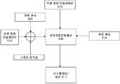
도 9는 제1 내지 제4 실시예 중 임의의 하나와 함께 사용을 위한 프로세서의 입력된 파라미터 및 출력된 파라미터를 도시하고 있는 개략 다이어그램이다.
도 10은 다수의 상이한 가스에 대해 밀도(kg/m3)의 함수로서 Y-축 상의 석영 결정 주파수(kHz)의 그래프를 도시하고 있다.
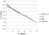
도 11은 최대 300 bar g의 압력에서 아르곤, 산소 및 아르곤:이산화탄소:산소 혼합물에 대해 X-축 상의 압력(bar g)의 함수로서 Y-축 상의 가스 밀도(kg/m3 단위)의 그래프를 도시하고 있다.
도 12는 최대 100 bar g의 압력에서 아르곤, 산소 및 아르곤:이산화탄소:산소 혼합물에 대해 X-축 상의 압력(bar g)의 함수로서 Y-축 상의 가스 밀도(kg/m3 단위)의 그래프를 도시하고 있다.
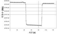
도 13은 가스가 퍼징될 때 X-축 상의 시간(초 단위)의 함수로서 Y-축 상의 주파수 변화(Hz 단위)를 도시하고 있는 그래프이다.
도 14는 X-축 상의 시간(초 단위)의 함수로서 분자량의 계산된 변화(Y-축 상의)를 도시하고 있는 도 13에 대응하는 그래프이다.
도 15는 설명된 실시예에 따른 방법을 도시하고 있는 흐름도이다.
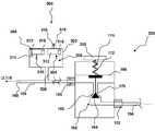
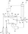
도 16은 가스 혼합기 장치를 도시하고 있는 본 발명의 실시예의 개략 다이어그램을 도시하고 있다.
도 17은 가스 혼합기 장치를 도시하고 있는 본 발명의 다른 실시예의 개략 다이어그램을 도시하고 있다.
도 18은 가스 혼합기 장치를 도시하고 있는 본 발명의 다른 실시예의 개략 다이어그램을 도시하고 있다.
도 19는 가스 혼합기 장치를 도시하고 있는 본 발명의 다른 실시예의 개략 다이어그램을 도시하고 있다.
도 20은 도 19 및 도 23의 실시예와 함께 사용을 위한 질량 유동 조립체를 도시하고 있다.
도 21은 도 19 및 도 23의 실시예와 함께 사용을 위한 대안적인 질량 유동 조립체를 도시하고 있다.
도 22는 질량 유량의 함수로서 결정 주파수의 그래프를 도시하고 있다.
도 23은 가스 혼합기 장치를 도시하고 있는 본 발명의 다른 실시예의 개략 다이어그램을 도시하고 있다.
도 24는 상이한 결정 유형이 주파수 거동의 그래프를 도시하고 있다.
도 25는 2개의 석영 결정을 포함하는 대안적인 센서 조립체를 도시하고 있는 개략 다이어그램이다.
도 26은 원격 전자 데이터 유닛을 사용하는 대안적인 장치를 도시하고 있다.1 is a schematic diagram of a gas cylinder and a regulator assembly.
2 is a schematic diagram illustrating a first embodiment of a regulator assembly and molecular weight meter.
3 is a schematic diagram illustrating a second embodiment of a regulator assembly and molecular weight meter.
4 is a schematic diagram illustrating a third embodiment of a regulator assembly and molecular weight meter.
5 is a schematic diagram showing a fourth embodiment of a molecular weight meter.
Figure 6 is a schematic diagram of a drive circuit for use with any one of the first through fourth embodiments.
7 is a schematic diagram illustrating an alternative drive circuit for use with any one of the first through fourth embodiments.
Figure 8 is a schematic diagram illustrating another alternative drive circuit for use with any one of the first through fourth embodiments.
9 is a schematic diagram illustrating input and output parameters of a processor for use with any one of the first through fourth embodiments.
Figure 10 shows a graph of the quartz crystal frequency (kHz) on the Y- axis as a function of the density (kg / m3) for a number of different gases.
11 shows a graph of gas density (in kg / m3 ) on the Y-axis as a function of pressure on the X-axis (bar g) for argon, oxygen and argon: carbon dioxide: oxygen mixtures at pressures up to 300 bar g Respectively.
12 is a graph of the gas density (in kg / m3 ) on the Y-axis as a function of the pressure on the X-axis (bar g) for argon, oxygen and argon: carbon dioxide: oxygen mixtures at pressures up to 100 bar g Respectively.
13 is a graph showing the frequency change (in Hz) on the Y-axis as a function of time on the X-axis (in seconds) as the gas is purged.
Figure 14 is a graph corresponding to Figure 13 showing the calculated change in molecular weight (on the Y-axis) as a function of time on the X-axis (in seconds).
15 is a flow chart illustrating a method according to the described embodiment.
Figure 16 shows a schematic diagram of an embodiment of the present invention illustrating a gas mixer arrangement.
Figure 17 shows a schematic diagram of another embodiment of the present invention showing a gas mixer arrangement.
Figure 18 shows a schematic diagram of another embodiment of the present invention showing a gas mixer arrangement.
Figure 19 shows a schematic diagram of another embodiment of the present invention showing a gas mixer arrangement.
Figure 20 shows a mass flow assembly for use with the embodiment of Figures 19 and 23;
Figure 21 shows an alternative mass flow assembly for use with the embodiment of Figures 19 and 23;
Figure 22 shows a graph of the determination frequency as a function of mass flow rate.
Figure 23 shows a schematic diagram of another embodiment of the present invention showing a gas mixer arrangement.
Figure 24 shows a graph of frequency behavior for different crystal types.
Figure 25 is a schematic diagram illustrating an alternative sensor assembly comprising two quartz crystals.
Figure 26 shows an alternative device using a remote electronic data unit.
도 1은 본 발명이 사용될 수도 있는 상황의 개략도를 도시하고 있다. 가스 실린더(100), 레귤레이터(150) 및 분자량 계량기(200)가 제공된다.Figure 1 shows a schematic diagram of a situation in which the present invention may be used. A
가스 실린더(100)는 가스 실린더 본체(102) 및 밸브(104)를 갖는다. 가스 실린더 본체(102)는 가스 실린더 조립체(10)가 편평한 표면 상에 지지되지 않은 체로 직립하는 것을 가능하게 하도록 배열된 편평한 베이스(102a)를 갖는 일반적으로 원통형 압력 용기를 포함한다.The
가스 실린더 본체(102)는 강, 알루미늄 및/또는 복합 재료로부터 형성되고, 최대 대략 900 bar g의 내부 압력을 견디도록 구성되고 배열된다. 개구(106)가 베이스(102a)에 대향하는 가스 실린더 본체(102)의 기단부에 위치되고, 밸브(104)를 수용하도록 구성된 나사산(도시 생략)을 포함한다.The
가스 실린더(100)는 내부 체적(V)을 갖는 압력 용기를 형성한다. 임의의 적합한 유체가 가스 실린더(100) 내에 수납될 수도 있다. 그러나, 본 실시예는 먼지 및/또는 수분과 같은 불순물이 없는 정화된 영구 가스에 관한 것이지만, 단지 그에만 제한되는 것은 아니다. 이러한 가스의 비제한적인 예는 산소, 질소, 아르곤, 헬륨, 수소, 메탄, 삼불화질소, 일산화탄소, 크립톤 또는 네온일 수도 있다.The gas cylinder (100) forms a pressure vessel having an internal volume (V). Any suitable fluid may be contained within the
밸브(104)는 하우징(108), 출구(110), 밸브체(112) 및 밸브 시트(114)를 포함한다. 하우징(108)은 가스 실린더 본체(102)의 개구(106)와 결합을 위한 상보형 나사산을 포함한다. 출구(110)는 가스 실린더(100)가 가스 조립체 내의 다른 부품들, 예를 들어 호스, 파이프 또는 다른 압력 밸브 또는 레귤레이터에 연결되는 것을 가능하게 하도록 구성되고 배열된다. 밸브(104)는 선택적으로 VIPR(일체형 압력 감소를 갖는 밸브)을 포함할 수도 있다. 이 상황에서, 레귤레이터(150)는 생략될 수도 있다.The
밸브체(112)는 출구(110)를 선택적으로 개방하거나 폐쇄하기 위해 파지 가능한 핸들(116)의 회전에 의해 밸브 시트(114)를 향해 또는 그로부터 이격하여 축방향으로 조정될 수 있다. 달리 말하면, 밸브 시트(112)를 향한 또는 그로부터 이격하는 밸브체(112)의 이동은 가스 실린더 본체(102)의 내부와 출구(110) 사이의 연통 통로의 영역을 선택적으로 제어한다. 이는 이어서 가스 실린더 조립체(100)의 내부로부터 외부 환경으로의 가스의 유동을 제어한다.The
레귤레이터(150)가 출구(110)의 하류측에 위치된다. 레귤레이터(150)는 입구(152) 및 출구(154)를 갖는다. 레귤레이터(150)의 입구(152)는 가스 실린더(100)의 출구(110)와 레귤레이터(150) 사이에 연통 경로를 제공하는 입구 파이프(156)에 연결된다. 레귤레이터(150)의 입구(152)는 가스 실린더(100)의 출구(110)로부터 고압에서 가스를 수용하도록 배열된다. 이는 임의의 적합한 압력일 수도 있지만, 일반적으로 출구(110)를 나오는 가스의 압력은 20 bar 초과, 더 가능하게는 100 내지 900 bar의 범위에 있을 것이다.The
출구(154)는 출구 파이프(158)에 연결된다. 커플링(160)이 출구 파이프(158)의 말단부에 위치되고, 가스가 요구되는 다른 파이프 또는 디바이스(도시 생략)로의 연결을 위해 구성된다.The
분자량 계량기(200)가 출구(154)와 커플링(160) 사이에서 출구 파이프(158)와 연통하여 위치된다. 분자량 계량기(200)는 레귤레이터(150)의 바로 하류측에 위치되고, 레귤레이터(150)의 하류측의 가스의 분자량(또는 가스 혼합물의 평균 분자량)을 결정하도록 배열된다.
레귤레이터(150) 및 분자량 계량기(200)는 도 2에 더 상세히 도시되어 있다.
본 실시예에서, 레귤레이터(150)는 단일 다이어프램 레귤레이터를 포함한다. 그러나, 당 기술 분야의 숙련자는 예를 들어 2 다이어프램 레귤레이터 또는 다른 장치와 같은 본 발명과 함께 사용될 수 있는 변형을 즉시 인식할 수 있을 것이다.In this embodiment, the
레귤레이터(150)는 입구(152) 및 출구(154)와 연통하는 밸브 영역(162)을 포함한다. 밸브 영역(162)은 밸브 시트(166)에 인접하여 위치된 포핏 밸브(poppet valve)(164)를 포함한다. 포핏 밸브(164)는 그 사이의 개구(170)를 각각 폐쇄하고 개방하도록 밸브 시트(166)를 향한 그리고 그로부터 이격하는 포핏 밸브(164)의 병진 이동을 가능하게 하도록 구성된 다이어프램(168)에 연결된다. 다이어프램(168)은 샤프트(174) 둘레에 위치된 스프링(172)에 의해 탄성적으로 편의된다.The
레귤레이터(150)는 최대 실린더 압력(예를 들어, 100 bar)에서 출구(110)로부터 가스를 수용하지만, 실질적으로 일정한 고정된 낮은 압력(예를 들어, 5 bar)에서 출구(154)로 가스를 전달하도록 작동 가능하다. 이는 개구(170)의 하류측 가스의 압력이 스프링(172)의 편의력에 대향하여 다이어프램(168) 상에 작용하도록 작동 가능한 피드백 기구에 의해 성취된다. 도 2의 실시예에서, 레귤레이터(150)는 고정된 압력 레귤레이터이고, 공지의 고정된 압력에서 출구(154)로부터 가스를 전달하도록 배열된다. 압력은 스프링(172)의 상대 편의력에 의해 결정된다.The
다이어프램(168)에 인접한 영역에서 가스의 압력이 지정된 레벨을 초과하면, 다이어프램(168)은 상향으로 이동하도록 작동 가능하다(도 2에 대해). 그 결과, 포핏 밸브(164)는 밸브 시트(166)에 더 근접하여 이동되어, 개구(170)의 크기를 감소시키고, 따라서 입구(152)로부터 출구(154)로의 가스의 유동을 제한한다. 일반적으로, 스프링(172)의 저항의 대항력 및 가스의 압력은 다이어프램의 평형 위치 및 따라서 출구(154)에서의 가스의 일정한 압력의 전달을 야기할 것이다.If the pressure of the gas in the region adjacent to the
분자량 계량기(200)는 하우징(202) 및 센서 조립체(204)를 포함한다. 하우징(202)은 임의의 적합한 재료, 예를 들어 강, 알루미늄 또는 복합재를 포함할 수도 있다. 하우징은 짧은 공급 파이프(208)를 거쳐 출구 파이프(158)의 내부와 연통하는 내부(206)를 갖는다. 따라서, 하우징(202)의 내부(206)는 출구 파이프(158)의 내부와 동일한 압력에 있다. 사용시에, 하우징(202)은 일반적으로 밀봉되고 외부 대기로부터 격리된다. 분자량 계량기(200)는 하우징(202) 내의 가스의 분자량을 측정하도록 배열된다. 대안적으로, 분자량 계량기(200)는 하우징(202) 내의 가스의 균질한 혼합물의 평균 분자량을 측정할 수도 있다.Molecular weight meter (200) includes a housing (202) and a sensor assembly (204). The
대안적으로, 하우징(202)은 출구 파이프(158)의 부분으로서 제공될 수 있다. 예를 들어, 출구 파이프(158)의 부분은 센서 조립체(204)를 수용하도록 확장될 수 있다. 대안적으로, 센서 조립체(204)의 단지 일부만이 파이프(158) 내에 위치될 수도 있고, 나머지는 외부에 위치되거나 그로부터 이격된다.Alternatively, the
부가적으로, 하우징(202)은 레귤레이터(150)의 일체형 부분을 형성할 수도 있다. 예를 들어, 센서 조립체(204)는 레귤레이터(150)의 출구(154) 내에 완전히 위치될 수도 있다. 당 기술 분야의 숙련자는 본 발명의 범주 내에 있는 변형예 및 대안예를 즉시 인식할 수 있을 것이다.Additionally, the
센서 조립체(204)는 구동 회로(212)에 연결된 석영 결정 오실레이터(210), 온도 센서(214) 및 배터리(216)를 포함한다. 이들 구성 요소들은 하우징(202) 내에 위치된다.The
구동 회로(212) 및 석영 결정 오실레이터(210)는 도 6 및 도 7을 참조하여 이하에 더 상세히 설명될 것이다. 온도 센서(214)는 서미스터(thermistor)를 포함한다. 임의의 적합한 서미스터가 사용될 수도 있다. 높은 정확성이 서미스터로부터 요구되지 않는다. 예를 들어, 0.5℃의 정확성이 본 실시예에 대해 적합하다. 따라서, 저가의 소형 부품들이 사용될 수 있다.The driving
프로세서(230)(도 8을 참조하여 도시되어 있고 이하에 설명됨)는 또한 개별적으로 또는 구동 회로(212)의 부분으로서 제공될 수도 있다.The processor 230 (shown with reference to Fig. 8 and described below) may also be provided individually or as part of the
이 장치에서, 석영 결정 오실레이터(210)는 분자량 계량기(200)의 하우징(202) 내에서 일정하게 정수압(isostatic pressure) 하에 있고, 따라서 압력 구배를 경험하지 않는다. 달리 말하면, 외부 분위기와 분자량 계량기(200)의 내부 구성 요소들 사이의 압력차로부터 발생하는 임의의 기계적 응력이 하우징(202)을 가로질러 표현된다.In this arrangement, the
그러나, 이는 필수적인 것은 아니다. 예를 들어, 단지 석영 결정 오실레이터(210) 및 온도 센서(214)만이 하우징(202) 내에 위치될 수도 있고, 센서 조립체(204)의 나머지는 그 외부에 위치된다.However, this is not essential. For example, only a
본 발명자들은 센서 조립체(204)의 단지 몇개의 구성 요소들만이 고압에 민감하다는 것을 발견하였다. 특히, 배터리와 같은 더 대형의 구성 요소들이 고압에 민감할 수 있다. 그러나, 리튬 배터리는 가스 실린더(100) 내에서 부닥치는 높은 압력 하에서 특히 양호하게 작동한다는 것이 발견되었다. 따라서, 배터리(216)는 리튬 전지를 포함한다. 그러나, 대안적인 적합한 전력 소스가 당 기술 분야의 숙련자에 의해 즉시 고려될 수 있을 것이다.The inventors have found that only a few components of the
하우징(202) 내의 완전히 있는 센서 조립체(204)의 배치는 레귤레이터(150)를 구성할 때 부가의 가요성을 제공한다. 특히, 하우징(202)의 강한 금속 또는 복합재 벽 내의 완전히 있는 비교적 취성 전자 부품의 배치는 환경적인 또는 우발적인 손상으로부터 상당한 보호를 제공한다. 이는 예를 들어 레귤레이터(150)를 포함하는 가스 실린더(100)가 가스 실린더, 중기계류 또는 거친 표면에 인접하여 위치되는 저장 영역 또는 저장소에서 특히 중요하다.The placement of the
부가적으로, 센서 조립체(204)의 내부 배치는 염, 물 및 다른 오염물과 같은 환경적인 조건으로부터 이들 구성 요소들을 보호한다. 이는 예를 들어 염 및 물 손상에 매우 민감한 고임피던스 회로가 센서 조립체(204)의 부분으로서 사용되게 할 것이다.Additionally, the internal placement of the
센서 조립체(204)의 내부 배치의 이익은 석영 결정 오실레이터(210)와 같은 고체 상태 센서 장치에 고유하다. 예를 들어, 부르동 게이지(Bourdon gauge)와 같은 종래의 압력 센서는 이 방식으로 위치될 수 없다. 결정계 센서는 일정한 압력에서 가스 내에 완전히 침지되어 작동할 수 있지만, 종래의 압력 센서는 정수압을 측정하는 것이 불가능하고 기능하기 위해 압력 구배를 욕한다. 따라서, 종래의 압력 게이지는 측정될 높은 압력과 분위기 사이에 배치되어야 한다. 이는 분자량 계량기(200)의 외부 구성 요소에 대한 손상의 위험을 증가시킨다.The benefit of the internal placement of the
분자량 계량기의 제2 실시예가 도 3에 도시되어 있다. 도 2의 제1 실시예와 공통인 도 3에 도시되어 있는 제2 실시예의 특징은 동일한 도면 부호가 배정되고, 여기서 재차 설명되지 않을 것이다.A second embodiment of a molecular weight meter is shown in Fig. The features of the second embodiment shown in FIG. 3, which are common to the first embodiment of FIG. 2, are assigned the same reference numerals and will not be described again here.
도 3의 실시예에서, 레귤레이터(250)는 레귤레이터(250)가 출구(154)로부터의 가스의 가변 출구 압력을 제공하도록 배열되는 점에서 도 2의 레귤레이터(150)와는 상이하다.3, the
이와 관련하여, 파지 가능한 핸들(252)이 제공되어 사용자가 스프링(172)의 편의력을 조정하는 것을 가능하게 한다. 이는 다이어프램(168)의 평형 위치를 이동시키고, 그 결과 포핏 밸브(164)와 밸브 시트(166) 사이의 평형 간격을 조정한다. 이는 출구(110)로부터의 고압 가스 유동이 그를 통해 통과할 수 있는 개구(170)의 치수의 조정을 가능하게 한다.In this regard, a
압력은 통상적으로 최대 약 20 bar g로 다양할 수도 있다. 그러나, 당 기술 분야의 숙련자는 대안 장치 및 레귤레이터(250)에 의해 공급될 수 있는 압력을 즉시 인식할 수 있을 것이다. 또한, 레귤레이터는 압력의 정밀한 조절이 요구되는 옥시-아세틸렌 용접과 같은 상황에 사용을 위한 2차 스테이지를 포함할 수도 있다.The pressure may typically vary up to about 20 bar g. However, those skilled in the art will readily recognize the pressure that can be supplied by the alternative apparatus and the
제2 실시예는 분자량 계량기(300)를 포함한다. 분자량 계량기(200)와 공통인 분자량 계량기(300)의 구성 요소들은 명료화를 위해 동일한 도면 부호가 배정된다.The second embodiment includes a
분자량 계량기(300)는 제1 실시예의 분자량 계량기(200)와 실질적으로 유사하다. 그러나, 분자량 계량기(300)는 하우징(202) 내에 배치된 압력 센서(302)를 더 포함한다. 임의의 적합한 압력 센서가 사용될 수도 있다.The
예를 들어, 압력 센서(302)는 압전-저항 다이어프램 센서를 포함할 수도 있다. 이러한 압력 센서는 통상적으로 그 내부에 형성된 압전-저항 스트레인 게이지를 갖는 기계가공된 실리콘 다이어프램을 포함한다. 다이어프램은 실리콘 또는 글래스 백플레이트에 융합된다. 스트레인 게이지는 통상적으로 그 출력이 측정된 압력에 정비례하는 휘트스톤 브리지(Wheatstone bridge)를 형성하도록 연결된다. 압력 센서(302)로부터의 출력은 이어서 프로세서(230)에 입력될 수 있다.For example, the
당 기술 분야의 숙련자는 본 발명과 함께 사용될 수 있는 대안적인 전자 압력 센서를 즉시 인식할 수 있을 것이다. 달리 말하면, 압력 센서(302)는 가스의 압력을 측정하고 그 측정의 전자 출력을 제공하는 것이 가능한 임의의 센서를 포함할 수도 있다.One of ordinary skill in the art will readily recognize alternative electronic pressure sensors that may be used with the present invention. In other words, the
이 구성에서, 석영 결정 오실레이터(210) 및 압력 센서(302)는 분자량 계량기(200)의 하우징(202) 내에 일정하게 정수압 하에 있고, 따라서 압력 구배를 경험하지 않는다. 달리 말하면, 외부 분위기와 분자량 계량기(300)의 내부 구성 요소들 사이의 압력차로부터 발생하는 임의의 기계적 응력이 하우징(202)을 가로질러 표현된다.In this configuration, the
본 발명의 제3 실시예가 도 4에 도시되어 있다. 도 3의 제2 실시예와 공통인 도 4에 도시되어 있는 제3 실시예의 특징은 동일한 도면 부호가 배정되고 여기서 재차 설명되지 않을 것이다.A third embodiment of the present invention is shown in Fig. The features of the third embodiment shown in FIG. 4, which are common to the second embodiment of FIG. 3, are assigned the same reference numerals and will not be described again here.
도 4의 실시예에서, 레귤레이터(250)는 제2 실시예의 레귤레이터(250)에 대응하고, 출구(154)로부터의 가스의 가변 출구 압력을 제공하도록 배열된다. 레귤레이터(250)의 구성 요소들은 이미 설명되어 있고 여기서 더 설명되지 않을 것이다.4, the
제3 실시예는 분자량 계량기(400)를 포함한다. 분자량 계량기(200, 300)와 공통인 분자량 계량기(400)의 구성 요소들은 명료화를 위해 동일한 도면 부호가 배정된다.The third embodiment includes a
분자량 계량기(400)는 제1 및 제2 실시예의 분자량 계량기(200, 300)와 실질적으로 유사하다. 그러나, 분자량 계량기(400)는 제2 실시예의 압력 센서(302)를 필요로 하지 않고 가변 압력 레귤레이터(250)와 함께 작동 가능하다.The
분자량 계량기(400)는 도관(402)을 포함한다. 도관(402)의 내부는 하우징(202)의 내부(206)와 연통한다. 도관(402)의 기단부는 짧은 파이프(208)의 바로 하류측에 배치되고 출구(154)와 연통하는 제한 오리피스(404)를 포함한다. 제한 오리피스(404)는 출구(154)로부터 도관(402)에 진입하는 가스의 압력을 제한하기 위해 물리적 제한을 제공하도록 배열된다. 따라서, 제한 오리피스(404)의 하류측의 도관(402) 내의 가스의 압력은 출구(154) 내의 가스의 압력보다 상당히 낮다.
도관(402)의 말단부(406)는 대기로 개방되어 있다. 말단부(406)는 하우징(202)의 하류측의 도관(402)의 섹션의 단부에 배치된다. 통상의 용례에 대해, 적합한 도관(402)은 2 mm의 영역 및 대략 100 mm의 길이의 보어를 가질 것이다. 이는 측정에 있어서 잠재적인 에러를 회피하기 위해 하우징(202)의 내부(206) 내로의 분위기 가스의 역확산이 없는 것을 보장하기 위한 것이다.The
도관(402)은 도 4에 본질적으로 선형으로서 도시되어 있지만, 도관(402)은 임의의 적합한 형상일 수 있다. 예를 들어, 더 소형의 장치는 더 작은 공간 내로 도관을 끼워맞춤하기 위해 미로 또는 코일 형상으로 도관(402)을 배열하기 위한 것일 것이다.Although
따라서, 제한 오리피스(404)와 도관(402)의 이격 말단부(406)(분위기 압력에 있음)의 조합된 효과는 하우징(202)의 내부(206)가 항상 분위기 압력에 또는 분위기 압력에 근접하게 있는 것이다. 이는 출구(154)의 하류측 및 제한 오리피스(404)의 상류측의 가스의 압력에 무관하다.The combined effect of the
그 결과, 압력은 항상 분위기 압력인 것으로 추정될 수 있기 때문에, 어떠한 압력 게이지도 요구되지 않는다. 보정이 요구되면(예를 들어, 분위기 압력이 낮은 높은 고도에서 작동할 때), 이는 프로세서(230)에 수동으로 입력될 수도 있다.As a result, no pressure gauge is required, since the pressure can always be assumed to be atmospheric pressure. If correction is required (e.g., when the atmospheric pressure is operating at a high elevation with low pressure), this may be manually entered into the
따라서, 특정 조건 하에서, 압력값은 자동으로 설정되거나 사용자에 의해 수동으로 입력될 수도 있고, 최종 압력값은 감지되는 가스 또는 가스들의 분자량을 결정하기 위해 프로세서(230)에 의해 사용되기 때문에, 어떠한 압력 센서도 요구되지 않는다.Thus, under certain conditions, the pressure value may be automatically set or manually entered by the user, and since the final pressure value is used by the
분자량 계량기의 제4 실시예가 도 5에 도시되어 있다. 제4 실시예는 분자량 계량기(500)에 관한 것이다. 분자량 계량기(500)는 제1 및 제2 실시예의 분자량 계량기(200, 300, 400)에 실질적으로 유사하다. 그러나, 분자량 계량기(500)는 제2 실시예의 압력 센서(302)를 요구하지 않고 가변 압력 레귤레이터(250)(또는 다른 가변 압력 가스 소스)와 함께 작동 가능하다.A fourth embodiment of the molecular weight meter is shown in Fig. The fourth embodiment relates to a
분자량 계량기(500)는 가스가 예를 들어 금속 불활성 가스(Metal Inert Gas: MIG) 용접 장치에서 대기로 통기되는 상황에서 작동 가능하다. 분자량 계량기(500)는 하우징(202) 내의 압력 조건이 분위기 압력인 것을 보장하기 위해, 레귤레이터(150)로부터 도관(158)을 따라 충분히 멀고 그리고 분위기 출구(160)로 충분히 근접한다.The
분자량 계량기(200, 300, 400)의 구성에 추가하여, 제2 구동 회로(512) 및 제2 배터리(516)에 연결된 석영 결정 오실레이터(510)를 포함하는 제2 센서 조립체(504)가 제공되어 있다. 제2 구동 회로(512) 및 제2 배터리(516)는 구동 회로(212) 및 배터리(216)에 실질적으로 유사하고, 여기서 더 설명되지 않을 것이다.A
제2 석영 결정 오실레이터(510)는 개방 하우징(518)을 통해 외부 부위기에 노출된다. 하우징(518)은 기계적 손상으로부터 제2 석영 결정 오실레이터(510)를 차폐하지만 제2 석영 결정 오실레이터(510)가 분위기에 노출되는 것을 가능하게 하도록 작동 가능하다. 하우징(518)은 그 말단부에 형성된 관통 구멍을 갖는 커버된 하우징을 포함할 수도 있다.The second
제2 센서 조립체(504)[석영 결정 오실레이터(510)를 포함함]는 분위기 압력의 정확한 결정을 가능하게 하도록 제공된다. 도 4의 실시예는 특정 조건 하에서 유효할 수도 있지만, 분위기 압력의 가변성은 분자량의 결정에 있어서의 에러를 유도할 수도 있다. 이는 가스의 혼합물(이후의 실시예에서 설명되는 바와 같이)이 이용되면 그리고 이전의 실시예들의 분자량 계량기들이 부정확한 측정을 제공할 수도 있는 경우에 특히 중요하다.The second sensor assembly 504 (including the quartz crystal oscillator 510) is provided to enable an accurate determination of the atmospheric pressure. Although the embodiment of Figure 4 may be effective under certain conditions, the variability of the atmospheric pressure may also induce errors in the determination of molecular weight. This is particularly important if mixtures of gases (as described in the Examples below) are used and the molecular weight meters of the previous embodiments may provide inaccurate measurements.
이하에 설명되는 바와 같이, 제2 석영 결정 오실레이터(510)는 가스의 밀도에 비례하는 주파수에서 공진한다. 그러나, 공기의 기체 조성은 잘 알려져 있고 일반적으로 일정하다. 따라서, 이하에 설명되는 바와 같은 식 7)을 사용하여, 압력은 공지의 밀도 및 공지의 분자량으로부터 결정될 수 있다. 이 구성은 향상된 정확성을 제공하고, 제조에 비용 효율적이고, 소형 크기를 갖는다.As described below, the second
분자량 계량기(500)의 나머지 구성 요소들은 제1 내지 제4 실시예의 분자량 계량기(200, 300, 400)의 것들에 유사하고, 여기서 더 설명되지 않을 것이다.The remaining components of the
제1 내지 제4 실시예 중 임의의 하나는 검출된 가스 상에 행해진 측정의 결과를 사용자에게 표시하기 위한 디스플레이(도시 생략)를 부가적으로 포함할 수도 있다. 대안적으로, 디스플레이는 분자량 계량기(200, 300, 400, 500)로부터 이격하여 위치될 수도 있고, 관련 데이터는 원격으로 통신할 수도 있다.Any one of the first to fourth embodiments may additionally include a display (not shown) for displaying to the user the result of the measurement made on the detected gas. Alternatively, the display may be located remotely from the molecular weight gauges 200, 300, 400, 500, and the associated data may be communicated remotely.
예를 들어, 제1 내지 제4 실시예 중 임의의 하나는 예를 들어 기지국과 원격 통신을 위한 안테나(도시 생략)를 더 포함할 수도 있다. 이는 이하에 설명될 것이다. 이 경우에, 안테나는 하우징(202)의 외부에 배치되고 와이어 또는 등가의 커넥터에 의해 센서 조립체(204)에 연결될 수도 있다.For example, any one of the first to fourth embodiments may further include an antenna (not shown) for remote communication with the base station, for example. This will be described below. In this case, the antenna is disposed outside the
안테나 자체는 임의의 적합한 통신 프로토콜을 사용하도록 적용되고 배열될 수도 있고, 예를 들어 비제한적인 리스트는 RFID, 블루투스, 적외선(IR), 802.11 무선, 주파수 변조(frequency modulation: FM) 전송 또는 셀 네트워크일 수도 있다.The antenna itself may be adapted and arranged to use any suitable communication protocol, for example, but not limited to, RFID, Bluetooth, infrared (IR), 802.11 wireless, frequency modulation Lt; / RTI >
대안적으로, 1-와이어 통신이 구현될 수도 있다. 1-와이어 통신은 통신을 위해 단지 단일의 금속 도전체만을 필요로 하고, 회로의 '복귀' 경로는 통신 디바이스들 사이의 공중을 통한 용량 결합에 의해 제공된다. 당 기술 분야의 숙련자는 본 명세서에 설명된 실시예들과 함께 사용될 수 있는 안테나(및 연계된 전송 하드웨어)의 대안을 즉시 인식할 수 있을 것이다.Alternatively, a one-wire communication may be implemented. The one-wire communication requires only a single metal conductor for communication, and the ' return ' path of the circuit is provided by capacitive coupling through the air between the communication devices. One of ordinary skill in the art will readily recognize alternatives to the antenna (and associated transmit hardware) that may be used with the embodiments described herein.
예를 들어, 통신은 실린더(100) 내로부터 음향 전송에 의해 실행될 수도 있다. 하우징(202) 내에 배치된 송신기는 음향 전송을 실행할 수도 있다. 송신기는 예를 들어 간단한 고정-주파수 압전 공진기를 포함할 수도 있다.For example, the communication may be performed by acoustic transmission from within the
상보형 수신기가 또한 요구되고, 이 부품은 분자량 계량기(200, 300, 400, 500)로부터 이격하여 배치될 수도 있고, 예를 들어 마이크로폰과 일체화된 위상 동기화 루프 톤 검출기와 같은 하드웨어를 포함할 수도 있다.A complementary receiver is also required and this component may be located remotely from the
센서 조립체(204)가 이제 도 6 및 도 7을 참조하여 더 상세히 설명될 것이다. 석영 결정 오실레이터(210)는 절단된 석영의 평면 섹션을 포함한다. 석영은 압전 거동을 나타내는 데, 즉 결정을 가로지르는 전압의 인가는 결정이 형상을 변경하게 하여, 기계적 힘을 생성한다. 역으로, 결정에 인가된 기계적 힘은 전하를 생성한다.The
석영 결정 오실레이터(210)의 2개의 평행한 표면은 벌크 결정을 가로질러 전기적 연결부를 제공하기 위해 금속화된다. 전압이 금속 접점에 이해 결정을 가로질러 인가될 때, 결정은 형상을 변경한다. 결정으로의 교류 전압의 인가에 의해, 결정은 발진하게 될 수 있다.Two parallel surfaces of the
석영 결정의 물리적 크기 및 두께는 석영 결정의 특성 또는 공진 주파수를 결정한다. 실제로, 결정(210)의 특성 또는 공진 주파수는 2개의 금속화된 표면 사이의 물리적 두께에 반비례한다. 석영 결정 오실레이터는 당 기술 분야에 잘 알려져 있고, 따라서 석영 결정 오실레이터(210)의 구조는 여기에 더 설명되지 않을 것이다.The physical size and thickness of the quartz crystal determines the characteristic or resonant frequency of the quartz crystal. Indeed, the characteristic or resonant frequency of the
부가적으로, 석영 결정의 공진 진동 주파수는 결정이 배치되는 환경에 따라 변할 것이다. 진공에서, 결정은 특정 주파수를 가질 것이다. 그러나, 이 주파수는 상이한 환경에서 변화할 것이다. 예를 들어, 유체에서, 결정의 진동은 주변 분자들에 의해 감쇠될 것이고, 이는 소정의 진폭에서 결정을 발진하는 데 요구된 에너지 및 공진 주파수에 영향을 미칠 것이다.Additionally, the resonant vibration frequency of the quartz crystal will vary depending on the environment in which the crystal is placed. In vacuum, crystals will have a certain frequency. However, this frequency will vary in different environments. For example, in a fluid, the oscillation of the crystal will be attenuated by the surrounding molecules, which will affect the energy and resonant frequency required to oscillate the crystal at a given amplitude.
또한, 결정 상의 주변 물질들의 침착은 진동하는 결정의 질량에 영향을 미쳐, 공진 주파수를 변경할 것이다. 물질의 이러한 흡착 또는 탈착은 흡수층이 결정 상에 형성되고 가스가 흡수됨에 따라 질량이 증가하는 통상적으로 사용된 선택적 가스 분석기를 위한 기초를 형성한다.Also, the deposition of the surrounding materials of the crystal phase will affect the mass of the oscillating crystal and will change the resonant frequency. This adsorption or desorption of the material forms the basis for a commonly used selective gas analyzer in which the absorption layer is formed on the crystal and the mass increases as the gas is absorbed.
그러나, 본 발명의 경우에, 어떠한 코팅도 석영 결정 오실레이터(210)에 도포되지 않는다. 실제로, 석영 결정 오실레이터(210) 상의 물질의 흡착 또는 탈착은 측정의 정확성이 영향을 받을 수도 있기 때문에 본 발명의 경우에 바람직하지 않다.However, in the case of the present invention, no coating is applied to the
도 6에 도시되어 있는 바와 같이, 본 실시예의 석영 결정 오실레이터(210)는 소리 굽쇠형(tuning-fork shaped)이고, 32.768 kHz의 공진 주파수에서 발진하도록 배열된 대략 5 mm 길이의 한 쌍의 살을 포함한다. 살(210a)은 석영의 평면 섹션에 형성된다. 포크의 살(210a)은 이들 살이 공진 주파수에서 서로를 향해 그리고 서로로부터 동기하여 이동하는 이들의 기본 모드에서 일반적으로 발진한다.As shown in FIG. 6, the
융합된(또는 비결정질) 석영은 매우 낮은 온도 의존성 팽창 계수 및 낮은 탄성 계수를 갖는다. 이는 온도에 따른 기본 주파수의 의존성을 감소시키고, 개시되는 바와 같이 온도 효과는 최소이다.Fused (or amorphous) quartz has a very low temperature dependent expansion coefficient and low modulus of elasticity. This reduces the dependence of the fundamental frequency on temperature, and the temperature effect is minimal as described.
부가적으로, AT 절단 또는 SC 절단된 석영을 사용하는 것이 바람직하다. 달리 말하면, 석영의 평면형 섹션은 특정 각도로 절단되어, 발진 주파수의 온도 계수가 대략 실온에서 넓은 피크를 갖는 포물선이 되도록 배열될 수 있게 된다. 따라서, 결정 오실레이터는 피크의 상부에서 기울기가 정확하게 0이 되도록 배열될 수 있다.In addition, it is preferable to use AT cut or SC cut quartz. In other words, the planar section of the quartz is cut at a specific angle so that the temperature coefficient of the oscillation frequency can be arranged to be a parabola having a broad peak at about room temperature. Thus, the crystal oscillator can be arranged such that the slope at the top of the peak is exactly zero.
이러한 석영 결정은 통상적으로 비교적 저비용으로 입수 가능하다. 진공중에서 사용되는 대부분의 석영 결정 오실레이터에 대조적으로, 본 실시예에서, 석영 결정 오실레이터(210)는 하우징(202) 내에서 압력 하에서 가스에 노출된다.Such quartz crystals are typically available at relatively low cost. In contrast to most quartz crystal oscillators used in vacuum, in this embodiment, the
석영 결정 오실레이터(210)를 구동하기 위한 구동 회로는 도 6에 도시되어 있다. 구동 회로(212)는 다수의 특정 기준에 부합해야 한다. 먼저, 본 발명의 석영 결정 오실레이터(210)는 소정 범위의 가스 압력에 노출될 수도 있고, 잠재적으로 압력은 분위기 압력[가스 실린더(100)가 비어 있을 때]으로부터 가스 실린더가 수소와 같은 압축된 가스를 포함하면 대략 900 bar g로 다양할 수도 있다. 따라서, 석영 결정 오실레이터(210)는 광범위한 압력 하에서 작동하도록(그리고, 비사용 기간 후에 재시작됨) 요구된다.A driving circuit for driving the
따라서, 석영 결정 오실레이터(210)의 품질(Q) 팩터는 사용 중에 상당히 변할 것이다. Q 팩터는 오실레이터 또는 공진기의 감쇠율에 관한 무차원 파라미터이다. 등가적으로, 이 Q 팩터는 그 중심 주파수에 대한 공진기의 대역폭을 특징화할 수도 있다.Thus, the quality (Q) factor of the
일반적으로, 오실레이터의 Q 팩터가 높을수록, 오실레이터의 저장된 에너지에 대한 에너지 손실율이 낮아진다. 달리 말하면, 높은 Q 팩터 오실레이터의 발진은 외부력의 부재시에 더 느리게 진폭이 감소한다. 더 높은 Q 팩터를 갖는 정현파 구동식 공진기(sinusoidally driven resonator)는 공진 주파수에서 더 큰 진폭을 공진하지만, 이들 공진기가 공진하는 해당 주파수 주위의 더 작은 주파수의 대역폭을 갖는다.Generally, the higher the Q factor of the oscillator, the lower the energy loss rate for the stored energy of the oscillator. In other words, the oscillation of the high Q factor oscillator decreases the amplitude more slowly in the absence of external force. A sinusoidally driven resonator with a higher Q factor resonates a larger amplitude at the resonant frequency, but has a smaller frequency bandwidth around that frequency at which these resonators resonate.
구동 회로(212)는 변화하는 Q 팩터에도 불구하고 석영 결정 오실레이터(210)를 구동하는 것이 가능해야 한다. 가스 실린더(100) 내의 압력이 증가함에 따라, 석영 결정 오실레이터(210)의 발진은 증가적으로 감쇠되게 될 것이고, Q 팩터는 강하할 것이다. 강하하는 Q 팩터는 구동 회로(212) 내의 증폭기에 의해 더 높은 이득이 제공되는 것을 요구한다. 그러나, 너무 높은 증폭이 제공되면, 구동 회로(212), 석영 결정 오실레이터(210)로부터의 응답이 구별하기가 어렵게 될 수도 있다. 이 경우에, 구동 회로(212)는 비관련 주파수에서 또는 석영 결정 오실레이터(210)의 비-기본 모드의 주파수에서 간단히 발진할 수도 있다.The
다른 제한으로서, 구동 회로(212)는 태양광 전지와 같은 보충 전력을 갖거나 갖지 않고 장시간 동안 비교적 저전력 배터리로 운전하기 위해 낮은 전력이어야 한다.As another limitation, the
구동 회로(212)가 이제 도 6을 참조하여 설명될 것이다. 석영 결정 오실레이터(210)를 구동하기 위해, 구동 회로(212)는 본질적으로 석영 결정 오실레이터(210)로부터 전압 신호를 취하고, 이를 증폭하고, 그 신호를 석영 결정 오실레이터(210)로 재차 공급한다. 석영 결정 오실레이터(210)의 기본 공진 주파수는 본질적으로 석영의 팽창 및 수축률의 함수이다. 이는 일반적으로 결정의 절단 및 크기에 의해 결정된다.The driving
그러나, 외부 팩터가 또한 공진 주파수에 영향을 미친다. 발생된 출력 주파수의 에너지가 회로 내의 손실에 일치할 때, 발진은 지속될 수 있다. 구동 회로(212)는 이 발진 주파수를 검출하고 유지하도록 배열된다. 주파수는 이어서 사용자에 의해 요구된 가스의 적절한 특성을 계산하고, 요구된다면 적합한 디스플레이 수단(이하에 설명되는 바와 같이)에 출력하는 데 사용된 프로세서(230)(도 9)에 의해 측정될 수 있다.However, the external factor also affects the resonance frequency. When the energy of the generated output frequency matches the loss in the circuit, the oscillation can continue. The
구동 회로(212)는 6 V 배터리(216)에 의해 전력 공급된다. 배터리(216)는 본 실시예에서 리튬 배터리를 포함한다. 그러나, 예를 들어 재충전형 및 비-재충전형의 모두의 다른 배터리 유형 및 태양 전지 장치와 같은 대안적인 전력 소스가 당 기술 분야의 숙련자에게 즉시 명백할 것이다.The
구동 회로(212)는 달링톤 쌍 공통 이미터 증폭기(Darlington pair Common Emitter amplifier)(218)를 더 포함한다. 달링톤 쌍은 제1 트랜지스터에 의해 증폭된 전류가 제2 트랜지스터에 의해 더 증폭되도록 구성된 2개의 쌍극 NPN 트랜지스터로 이루어지는 복합 구조체를 포함한다. 이 구성은 개별적으로 취해지는 각각의 트랜지스터에 비교할 때 더 높은 전류 이득이 얻어질 수 있게 한다. 대안적인 PNP 쌍극 트랜지스터가 사용될 수도 있다.The driving
달링톤 쌍(218)은 단일 트랜지스터(T1) 공통 이미터 증폭기(220)로부터 피드백 구성으로 배열된다. NPN 쌍극 접합 트랜지스터가 도 4에 도시되어 있다. 그러나, 당 기술 분야의 숙련자는 예를 들어, 쌍극 접합 PNP 트랜지스터 또는 금속 산화물 반도체 전계 효과 트랜지스터(Metal Oxide Semiconductor Field Effect Transistor: MOSFET)와 같은 사용될 수도 있는 대안적인 트랜지스터 장치를 인식할 수 있을 것이다.
변형예로서, 자동 이득 제어(도시 생략)가 달링톤 쌍(218)과 공통 이미터 증폭기(220) 사이의 피드백 루프에서 구현될 수 있다. 이는 예를 들어 도 6에 도시되어 있는 최우측 22k 저항기 대신에 배치된 전위차계, 가변 저항기 또는 다른 적합한 구성 요소의 형태를 취할 수도 있다.As an alternative, automatic gain control (not shown) may be implemented in the feedback loop between
자동 이득 제어는 압력에 따른 Q-팩터의 변화 및 공급 전압의 변화(예를 들어, 저배터리 조건 하에서)를 보상하는 것을 가능하게 한다. 자동 이득 제어는 저압 용례에 특히 적용 가능할 수도 있다.The automatic gain control makes it possible to compensate for changes in the Q-factor with pressure and changes in the supply voltage (for example, under low battery conditions). Automatic gain control may be particularly applicable for low pressure applications.
구동 회로(212)는 버퍼 증폭기(222)로서 작용하는 다른 NPN 이미터 팔로워 트랜지스터(follower transistor)(T2)를 포함한다. 버퍼 증폭기(222)는 회로와 외부 환경 사이의 버퍼로서 기능하도록 배열된다. 그러나, 이 특징은 선택적이고, 필요하지 않을 수도 있는 데, 예를 들어 FET는 회로(212)를 구동하도록 직접 연결될 수 있다.The
캐패시터(224)가 석영 결정 오실레이터(210)와 직렬로 배치된다. 캐패시터(224)는 본 예에서, 100 pF의 값을 갖고, 석영이 예를 들어 염 또는 다른 침착된 물질에 의해 오염되게 되는 상황에서 구동 회로(212)가 석영 결정 오실레이터(210)를 구동하는 것을 가능하게 한다.A
대안적인 구동 회로(240)가 이제 도 7을 참조하여 설명될 것이다. 구동 회로(240)는 전술된 구동 회로(204) 대신에 사용될 수도 있다. 전술된 구동 회로(204)에 대조적으로, 구동 회로(240)는 도 6의 회로의 달링톤 쌍 대신에 공통 드레인 금속 산화물 반도체 전계 효과 트랜지스터(MOSFET)를 포함한다. MOSFET(242)은 증폭기 스테이지의 출력 임피던스가 석영 결정 오실레이터(202)의 고임피던스에 일치되는 것을 가능하게 하는 고임피던스 입력으로서 기능한다. 달리 말하면, MOSFET(242)은 석영 결정 오실레이터(202) 상의 전기 부하를 감소시키기 위해 고입력 임피던스를 갖는 단위 이득을 제공한다.An
공통 드레인 MOSFET 증폭기(242)의 출력은 2개의 연속적인 단일 트랜지스터(Q2, Q3) 공통 이미터 증폭기(244)로 공급된다. 저항기(R6, R8)는 트랜지스터를 위한 네거티브 피드백 및 바이어싱 전류의 모두를 제공한다. 공통 이미터 증폭기(244)는 석영 결정 오실레이터(202)의 오실레이터를 증폭하기 위해 고이득을 제공하고, 본 실시예에서 NPN 쌍극 접합 트랜지스터를 포함한다. 그러나, 당 기술 분야의 숙련자는 예를 들어 쌍극 접합 PNP 트랜지스터 또는 MOSFET과 같은 사용될 수도 있는 대안적인 트랜지스터 장치를 인식할 수 있을 것이다.The output of the common
캐패시터(246)가 석영 결정 오실레이터(202)와 접지 사이에 연결된다. 캐패시터(246)는 본 실시예에서 석영 결정 오실레이터(202)로의 구동을 증가시키도록 작동 가능하다.A
저항기(248)는 석영 결정 오실레이터(202)와 직렬로 연결된다. 저항기(248)는 본 실시예에서 56 kΩ의 값을 갖고, 단지 파형의 점진적인 변화에 따라 광범위한 압력에 걸쳐 회로가 발진하는 것을 가능하게 하기 위해 석영 결정 오실레이터(202)의 발진을 감쇠한다.
구동 회로(240)는 3 V 배터리(249)에 의해 전력 공급된다. 배터리(249)는 본 실시예에서 리튬 배터리를 포함한다. 그러나, 재충전형 및 비-재충전형의 모두인 다른 배터리 유형 및 태양 전지 장치와 같은 대안적인 전력 소스가 당 기술 분야의 숙련자에게 즉시 명백할 것이다. 대안적으로, 간선 공급(mains supply) 장치가 DC 정류 및 적절한 전압 감소 후에 사용될 수도 있다.The driving
다른 대안적인 구동 회로(260)가 이제 도 8을 참조하여 설명될 것이다. 도 8에 도시되어 있는 구동 회로는 피어스 오실레이터(Pierce oscillator)에 유사하게 구성된다. 피어스 오실레이터는 디지털 IC 클럭 오실레이터로부터 알려져 있다. 본질적으로, 구동 회로(260)는 단일의 디지털 인버터(트랜지스터의 형태)(T), 3개의 저항기(R1, R2, RS), 2개의 캐패시터(C1, C2) 및 석영 결정 오실레이터(210)를 포함한다.Another
이 장치에서, 석영 결정 오실레이터(210)는 고도로 선택적 필터 요소로서 기능한다. 저항기(R1)는 트랜지스터(T)용 부하 저항기로서 작용한다. 저항기(R2)는 그 선형 작동 영역에서 인버터(T)를 바이어싱하는 피드백 저항기로서 작용한다. 이는 인버터(T)가 고이득 반전 증폭기(inverting amplifier)로서 작동하는 것을 가능하게 한다. 다른 저항기(R3)가 인버터(T)의 출력과 석영 결정 오실레이터(210) 사이에 사용되어 이득을 제한하고 회로 내의 바람직하지 않은 발진을 감쇠한다.In this arrangement, the
석영 결정 오실레이터(210)는 C1 및 C2와 조합하여 Pi 네트워크 대역통과 필터를 형성한다. 이는 180도 위상 시프트 및 출력으로부터의 전압 이득이 석영 결정 오실레이터의 대략 공진 주파수에서 입력되는 것을 가능하게 한다. 전술된 구동 회로(260)는 비교적 적은 구성 요소들을 포함하기 때문에 신뢰적이고 제조가 저렴하다.The
전술된 바와 같이, 센서 조립체(204)는 석영 결정 오실레이터(210) 및 구동 회로(212)로부터 입력을 수신하는 프로세서(230)를 포함할 수도 있다. 프로세서(230)는 ASIC 또는 FPGA와 같은 임의의 적합한 장치를 포함할 수도 있다.As discussed above, the
프로세서(230)는 가스의 분자량(또는 가스의 균질 혼합물의 평균 분자량)의 결정을 계산하고, 요구된다면 표시하고 통신하도록 프로그램된다. 프로세서(230)의 주 입력 및 출력의 개략도가 도 9에 도시되어 있다.
석영 결정 오실레이터(210)와 함께 사용될 때, 프로세서(230)는 구동 회로(212)를 포함하는 센서 조립체(204)로부터 신호의 주파수(f) 또는 주기를 측정하도록 구성될 수도 있다. 이는 예를 들어 고정된 시간에 걸쳐 발진을 카운팅함으로써 성취될 수도 있고, 알고리즘 또는 룩업 테이블을 사용하여 그 주파수를 밀도값으로 변환할 수도 있다. 이 값은 프로세서(230)로 통과된다.When used with a
프로세서(230)는 또한 온도 센서(214)로부터 측정된 온도(T)를 수신한다. 또한, 프로세서(230)는 압력 센서(302)(존재한다면)로부터 또는 고정된 압력값으로부터 압력값을 수신한다. 이 값은 예를 들어 분자량 계량기(400, 500)가 단지 분위기 압력에서만 사용되는 또는 분자량 계량기(200)의 경우에서와 같이 고정된 압력 레귤레이터의 출구에 사용되는 상황에 자동으로 설정될 수도 있다. 이 상황에서, 고정된 압력값은 프로세서(230)에 입력된다. 대안적으로, 고정된 압력값은 사용자에 의해 수동으로 입력될 수도 있다.The
다른 대안으로서, 센서 조립체(504)[구동 회로(512)를 포함함]로부터의 신호의 주파수(f) 또는 주기는 프로세서(230)에 의해 수신될 수도 있다. 이는 예를 들어 고정된 시간에 걸쳐 발진을 카운팅함으로써 성취될 수도 있고, 알고리즘 또는 룩업 테이블을 사용하여 그 주파수를 압력값으로 변환할 수도 있다(주파수는 밀도에 비례하고, 밀도는 공기의 기체 조성이 알려질 때 압력에 비례하기 때문에). 이 값은 프로세서(230)로 통과된다.Alternatively, the frequency (f) or period of the signal from the sensor assembly 504 (including the drive circuit 512) may be received by the
프로세서(230)는 공급된 입력에 기초하여, 석영 결정 오실레이터(210)가 침지되는 가스의 분자량을 결정하기 위해 계산을 수행하도록 배열된다. 프로세서(230)는 분자량 계량기(200, 300, 400, 500) 중 임의의 하나의 부분을 포함할 수도 있다.The
일단 분자량이 결정되어 있으면, 이 데이터는 로컬 메모리 내에 저장될 수도 있고, 디스플레이 스크린 상에 표시될 수도 있고 또는 원격 스테이션으로 전송될 수도 있다.Once the molecular weight has been determined, this data may be stored in local memory, displayed on a display screen, or transmitted to a remote station.
프로세서(230)는 선택적으로 상이한 가스에 대해 가능한 소프트웨어 및 하드웨어 내의 상이한 특징을 갖고, 모든 분자량 계량기(200)에서 대량 생산이 동일하도록 설계될 수도 있다.
부가적으로, 프로세서(230)는 또한 프로세서(230) 및 구동 회로(212)와 석영 결정 오실레이터(210)와 같은 부가의 구성 요소를 커버할 수도 있는 대기 또는 "슬립(sleep)" 모드의 구현을 통해 전력 소비를 최소화하도록 구성될 수도 있다.In addition, the
다양한 방안이 구현될 수도 있는 데, 예를 들어 프로세서(230)는 매 11초마다 10초 동안 대기 상태에 있을 수도 있다. 또한, 프로세서(230)는 이들 구성 요소가 대부분의 시간 동안 대기 상태가 되어, 단지 매 30초마다 ½초 동안 더 전력이 필요한(power-hungry) 구성 요소를 스위칭 온하도록 석영 결정 오실레이터(210)와 구동 회로(212)를 제어할 수도 있다.Various schemes may be implemented, for example, the
센서 조립체(204)의 이론 및 작동이 이제 도 10 내지 도 14를 참조하여 설명될 것이다.The theory and operation of the
석영 결정 오실레이터(210)는 그가 배치되어 있는 유체의 밀도에 의존하는 공진 주파수를 갖는다. 발진 소리 굽쇠형 평면형 결정 오실레이터를 가스에 노출하는 것은 결정의 공진 주파수의 시프트 및 감쇠를 유도한다(진공 내에서 결정의 공진 주파수에 비교할 때). 이에 대한 다수의 이유가 존재한다. 결정의 발진에 대한 가스의 감쇠 효과가 존재하지만, 소리 굽쇠 결정 오실레이터(210)의 진동 살(210a)에 인접한 가스는 오실레이터의 유효 질량을 증가시킨다. 이는 단면(one-sided) 고정된 탄성보(elastic beam)의 움직임에 따른 석영 결정 오실레이터의 공진 주파수의 감소를 유도한다.The

여기서, f는 발진 주파수이고, f0는 진공 내에서 발진 주파수이고, ρ는 가스 밀도이고, M0는 상수이다.Where f is the oscillation frequency, f0 is the oscillation frequency in vacuum, ρ is the gas density, and M0 is a constant.
밀도(ρ)는 거의 모든 경우에 M0에 비교하여 작을 것이어서, 식은 선형식에 의해 근사될 수 있는 데,Density (ρ) is smaller geotyieoseo and in almost all cases compared to0 M, to which can be approximated by a line equation form,

이는 식 3)에서 설명된 바와 같이 f0로부터 주파수 편차(Δf)의 항으로 재표현될 수 있다.This can be re-expressed in terms of frequency deviation (f) from f0 as described in equation (3).

따라서, 양호한 근사로, 주파수의 변화는 석영 결정 오실레이터가 노출되는 가스의 밀도의 변화에 비례한다. 도 10은 다수의 상이한 가스/가스 혼합물에 대해, 석영 결정 오실레이터(210)의 공진 주파수가 밀도의 함수로서 선형으로 변화하는 것을 도시하고 있다.Thus, with a good approximation, the change in frequency is proportional to the change in the density of the gas to which the quartz crystal oscillator is exposed. FIG. 10 shows that for many different gas / gas mixtures, the resonant frequency of the
일반적으로, 석영 결정 오실레이터(210)의 감도는 주파수의 5% 변화가 예를 들어 분위기 압력에 비교할 때 250 bar에서 산소 가스(원자 질량 번호 32를 가짐)로 보여지게 되는 것이다. 이러한 압력 및 가스 농도는 대부분의 가스에 대해 일반적으로 137 내지 450 bar g, 헬륨 및 수소에 대해 최대 700 내지 900 bar g인 영구 가스에 대해 사용된 저장 실린더의 전형이다.In general, the sensitivity of the
석영 결정 오실레이터(210)는 상업적으로 공급된 가스를 위한 분자량 계량기의 부분을 형성하는 밀도 센서로서 사용을 위해 특히 적합하다. 가스의 밀도를 정확하게 감지하기 위해, 가스는 상업적으로 공급되는 가스로, 그러나 공기에 의해서는 아니라 또는 일반적인 압력 모니터링 상황에서 보장되는 먼지 및 액체의 액적이 없어야 할 필요가 있다.The
일단 밀도값이 석영 결정 오실레이터(210)로부터 얻어지면, 가스의 분자량은 이하의 식으로부터 결정될 수 있고,Once the density value is obtained from the

여기서, P는 가스의 압력이고, V는 가스의 체적이고, n은 가스의 몰수이고, R은 가스 상수이고, T는 온도이다. V를 제거하기 위해, 계속하면Where P is the pressure of the gas, V is the volume of the gas, n is the number of moles of gas, R is the gas constant, and T is the temperature. To remove V, continue

그리고And

여기서, MW는 가스의 분자량이고, M은 가스의 질량이다. 따라서, 식 5)에 V를 치환하면Where MW is the molecular weight of the gas and M is the mass of the gas. Therefore, when V is substituted into the equation (5)

여기서, α는 RT에 동일한 상수이고, 여기서 R은 가스 상수이고, T는 켈빈 단위의 절대 온도이다. 따라서, 가스의 공지의 압력, 밀도 및 온도에 대해, 가스의 분자량(또는 가스의 혼합물의 경우에 평균 분자량)이 결정될 수 있다. 상기 유도는 가스가 이상 기체에 근접하는 것으로 가정한다.Where alpha is the same constant in RT, where R is the gas constant and T is the absolute temperature in Kelvin. Thus, for a known pressure, density and temperature of the gas, the molecular weight of the gas (or the average molecular weight in the case of a mixture of gases) can be determined. The derivation assumes that the gas is close to the ideal gas.
상기 식 7)에 기초하여, 압력이 알려져 있으면(예를 들어, 압력이 분위기 압력 또는 고정된 압력 레귤레이터의 출력에 있는 경우), 단지 가스의 온도 및 밀도만이 분자량의 정확한 결정을 제공하는 데 필요하다. 부수적으로, 압력 및 온도가 적당한 정도로 알려지면, 가스의 분자량은 밀도 또는 달리 말하면 사전 결정된 팩터만큼 곱해진 석영 결정 오실레이터의 공진 주파수에 효과적으로 비례한다.Based on Equation 7 above, only the temperature and density of the gas are needed to provide an accurate determination of the molecular weight if the pressure is known (e.g., when the pressure is at the atmospheric pressure or at the output of the fixed pressure regulator) Do. Incidentally, if the pressure and temperature are known to an adequate degree, the molecular weight of the gas is effectively proportional to the resonance frequency of the quartz crystal oscillator multiplied by density or otherwise by a predetermined factor.
따라서, 가스의 분자량(또는 혼합물의 평균)은 밀도의 함수로서 압력의 구배로부터 결정될 수 있는 데, 여기서 식 7)을 고쳐쓰면, 이하의 식을 제공한다.Thus, the molecular weight of the gas (or the average of the mixture) can be determined from the pressure gradient as a function of density, where Eq. 7) is rewritten to give the following equation.

도 11 및 도 12는 분자량 측정의 실험 데이터를 도시하고 있다. 양 그래프는 동일한 4개의 가스에 대해 X-축 상에 압력(bar g 단위)의 함수로서 Y-축 상에 밀도(kg/m3 단위)를 도시하고 있다. 2개의 그래프는 도 10이 최대 300 bar g의 압력을 도시하고 있고, 도 11이 단지 최대 100 bar g의 압력을 도시하고 있는 점을 제외하고는 동일하다.Figures 11 and 12 show experimental data of molecular weight measurements. Both graphs show the density (in kg / m3 ) on the Y-axis as a function of pressure (bar g units) on the X-axis for the same four gases. The two graphs are the same except that Fig. 10 shows a pressure of up to 300 bar g and Fig. 11 only shows a pressure of up to 100 bar g.
사용된 4개의 가스는 도 10에 도시된 바와 같이 페로맥스 15(Ferromax 15)(아르곤: 이산화탄소: 산소 혼합물), 헬륨, 이산화탄소 및 산소이다. 라인의 기울기는 분자량에 비례한다(RT가 세 경우 모두 일정하다고 가정함). 따라서, 석영 결정 오실레이터(210)는 가스 또는 가스의 혼합물의 분자량을 용이하게 결정할 수 있다.The four gases used are Ferromax 15 (argon: carbon dioxide: oxygen mixture), helium, carbon dioxide and oxygen as shown in FIG. The slope of the line is proportional to the molecular weight (assuming all three RTs are constant). Thus, the
또한, 석영 결정 오실레이터(210)의 높은 정확성은 백만분율의 분해능을 갖는 매우 높은 정확성으로 측정되는 것을 가능하게 한다. 높은 밀도 및 압력에서 석영 밀도 센서(202)의 선형 응답과 결합하여, 높은 정확도는 H2 및 He와 같은 매우 가벼운 가스의 분자량이 정확하게 측정되는 것을 가능하게 한다.In addition, the high accuracy of
게다가, 도 5의 실시예의 경우에, 분자량 계량기(500)는 분위기 압력을 결정하도록 작동 가능한 부가의 석영 결정 오실레이터(510)를 포함한다. 이 경우에, 식 8)은 유사하게 고쳐쓰여져 식 9)를 제공할 수 있다.In addition, in the case of the embodiment of FIG. 5, the

전술된 바와 같이, 공기의 조성(즉, ~78% 질소, ~21% 산소, ~1% 기타)은 일반적으로 비교적 일정하고, 따라서 식 9)는 석영 결정 오실레이터(510)에 의한 밀도 측정으로부터 압력을 결정하는 데 사용될 수 있다.The composition of the air (i.e., ~ 78% nitrogen, ~ 21% oxygen, ~ 1%, etc.) is generally relatively constant, . ≪ / RTI >
이 기술의 일 유용한 용례는 퍼지 검출이다. 도 13 및 도 14는 가스 퍼지 검출의 실험 데이터를 도시하고 있다. 이러한 정보는 파이프라인의 자동 궤도 용접과 같은 상황에서 매우 중요하다.One useful application of this technique is purge detection. 13 and 14 show experimental data of gas purge detection. This information is very important in situations such as auto-track welding of pipelines.
도 13은 질소 환경 내로 5 리터/분에서 아르곤의 유동, 이어서 질소의 재충전에 대한 X-축 상의 시간(초 단위)의 함수로서 Y-축 상의 주파수(Hz)의 그래프를 도시하고 있다. 명백하게, 주파수의 단계적 변화가 높은 정확도로 즉시 측정 가능하다.Figure 13 shows a graph of the frequency (Hz) on the Y-axis as a function of the flow of argon at 5 liters / min into a nitrogen environment followed by the time in seconds on the X-axis for nitrogen refill. Obviously, step changes in frequency are immediately measurable with high accuracy.
도 14는 이 경우에 Y-축이 분자량(질량 단위)을 판독하도록 캘리브레이팅되어 있는 것을 제외하고는 동일한 데이터를 도시하고 있다.Figure 14 shows the same data, except that in this case the Y-axis is calibrated to read the molecular weight (in mass units).
이들 도면들은 대부분의 정상 사용에 대해, 가스의 분자량이 석영 결정 오실레이터를 사용하여 즉시 결정될 수 있는 것을 명백하게 도시하고 있다. 또한, 하나의 가스가 다른 가스로 퍼지될 때 발생하는 분자량의 변화는 명백하게 규정되고 식별 가능하다. 따라서, 가스 정화 중에 분자량 변화는 석영 결정 오실레이터(210) 및 구동 회로(204)를 사용하여 충분한 정확도 및 시간 분해능으로 계산될 수 있다.These figures clearly show, for most normal uses, that the molecular weight of the gas can be determined immediately using a quartz crystal oscillator. In addition, the change in molecular weight that occurs when one gas is purged with another gas is clearly defined and identifiable. Thus, the molecular weight change during gas purification can be calculated with sufficient accuracy and time resolution using
실시예의 작동 방법이 이제 도 15를 참조하여 설명될 것이다. 이하에 설명되는 방법은 전술된 제1 내지 제4 실시예의 각각에 적용 가능하다.
An operating method of the embodiment will now be described with reference to FIG. The method described below is applicable to each of the first to fourth embodiments described above.
단계 550: 측정 초기화Step 550: Initialize the measurement
단계 550에서, 하우징(202) 내의 가스의 분자량의 측정이 초기화된다. 이는 예를 들어 사용자가 하우징(202)의 외부의 버튼을 누름으로써 활성화될 수도 있다. 대안적으로, 측정은 원격 연결부에 의해, 예를 들어 무선 네트워크를 가로질러 전송되고 안테나를 통해 분자량 계량기(200, 300, 400, 500)에 의해 수신된 신호에 의해 초기화될 수도 있다.At
다른 대안 또는 추가로서, 분자량 계량기(200, 300, 400, 500)는 원격으로 또는 타이머에 의해 초기화되도록 구성될 수도 있다. 방법은 단계 552로 진행한다.
As an alternative or in addition, the
단계 552: 석영 결정 오실레이터 구동Step 552: Quartz crystal oscillator driven
일단 초기화되면, 구동 회로(212)는 석영 결정 오실레이터(210)를 구동하는 데 사용된다. 초기화 중에, 구동 회로(212)는 결정(210)을 가로질러 랜덤 노이즈 AC 전압을 인가한다. 그 랜덤 전압의 적어도 일부는 결정(210)이 발진하게 하기 위해 적합한 주파수에 있을 것이다. 결정(210)은 이어서 그 신호와 동기하여 발진하기 시작할 것이다.Once initialized, the
이해될 수 있는 바와 같이, 석영 결정 오실레이터(210)는 본질적으로 결정 자체의 공진 주파수가 측정되기 때문에 자급형 검출기 및 드라이버이다.As can be appreciated, the
압전 효과에 의해, 석영 결정 오실레이터(210)의 운동은 이어서 석영 결정 오실레이터(210)의 공진 주파수 대역 내의 전압을 발생할 것이다. 구동 회로(212)는 이어서 석영 결정 오실레이터(210)에 의해 발생된 신호를 증폭하여, 석영 결정 오실레이터(202)의 주파수 대역 내에서 발생된 신호가 구동 회로(212)의 출력을 지배하게 된다. 석영 결정의 좁은 대역은 모든 원하지 않는 주파수를 필터링하고, 구동 회로(212)는 이어서 기본 공진 주파수(f)에서 석영 결정 오실레이터(210)를 구동한다. 일단 석영 결정 오실레이터(210)가 특정 공진 주파수에서 안정화되면, 방법은 단계 554로 진행한다.
Due to the piezoelectric effect, movement of the
단계 554: 석영 결정 오실레이터의 공진 주파수 측정Step 554: Measurement of resonance frequency of quartz crystal oscillator
공진 주파수(f)는 하우징(202) 내의 환경 조건에 의존한다. 본 실시예에서, 공진 주파수의 변화(Δf)는 양호한 근사로, 하우징(202)의 내부(206)의 가스의 밀도의 변화에 크기가 비례하고, 밀도 증가에 따라 감소할 것이다.The resonant frequency f depends on the environmental conditions in the
측정을 행하기 위해, 석영 결정 오실레이터(210)의 주파수는 대략 1 s의 기간 동안 측정된다. 이는 판독이 안정화되는 것을 가능하게 하고 정확한 측정을 결정하기 위해 충분한 오실레이터 카운팅되게 할 수 있다. 주파수의 측정은 프로세서(230)에서 수행된다. 프로세서(230)는 또한 측정이 시작될 때 시간(T1)을 로그할 수도 있다.To perform the measurement, the frequency of the
일단 주파수가 측정되면, 방법은 단계 556으로 진행한다.
Once the frequency is measured, the method proceeds to step 556.
단계 556: 가스의 온도 측정Step 556: Measurement of gas temperature
단계 556에서, 온도 센서(214)는 하우징(202) 내의 가스의 온도를 측정한다. 이 측정은 단계 554에서 측정된 주파수 변화로부터 분자량의 계산의 정확성을 향상시키기 위해 수행된다.In
온도 측정은 특히 정확해야 할 필요는 없다. 예를 들어, 온도 센서(214)가 0.5℃로 정확하면, 이는 이후의 단계들에서 분자량의 계산을 위해 요구되는 절대 온도값에 단지 대략 600분의 1의 에러에 대응한다(정상 분위기 압력을 가정함).The temperature measurement need not be particularly accurate. For example, if the
대안으로서, 이 단계는 프로세서(230)에 입력되는 고정된 온도값을 간단히 수반할 수도 있다. 이는 예를 들어 공지의 온도 환경이 사용되는 상황에서 발생할 수도 있다. 이 경우에, 온도 센서(214)는 요구되지 않는다.
Alternatively, this step may simply involve a fixed temperature value that is input to the
단계 558: 가스의 압력의 결정Step 558: Determination of the pressure of the gas
일단 석영 결정 오실레이터(210)의 주파수가 단계 554에서 만족스럽게 측정되어 있고 온도가 단계 556에서 측정되어 있으면, 프로세서(230)는 이어서 하우징(202)의 내부(206) 내의 가스의 압력을 결정한다.Once the frequency of the
이는 하우징(202) 내의 측정된 압력에 비례하는 전기 신호를 제공하는 압력 센서(302)(제공되면)로부터 입력값으로 행해질 수도 있다. 이는 제2 및 제4 실시예에 적용된다.This may be done from an input value from a pressure sensor 302 (if provided) that provides an electrical signal proportional to the measured pressure within the
대안적으로, 압력값은 프로세서(230)에 수동으로 또는 압력이 적당한 정도로 알려져 있으면 자동으로 입력될 수도 있다. 이는 고정된 압력 레귤레이터의 출력에 대응할 수도 있고(제1 실시예에서와 같이) 또는 분위기 압력에 대응할 수도 있다(제3 실시예에서와 같이).
Alternatively, the pressure value may be input to the
단계 560: 가스의 분자량의 결정Step 560: Determination of the molecular weight of the gas
이는 가스의 밀도(ρ), 압력(P) 및 온도(T)가 알려져 있으면 상기 식 8)을 사용하여 행해진다. 따라서, 단계 554에서 측정된 바와 같은 공진 주파수, 단계 556에서 측정된 하우징(202) 내의 가스의 알려진 온도(T) 및 단계 558에서 결정된 바와 같은 가스의 알려진 압력을 알고 있으면, 분자량(또는 가스의 균질 혼합물에 대한 평균 분자량)의 정확한 측정이 행해질 수 있다. 방법은 이어서 단계 562로 진행한다.
This is done using equation (8) above if the density, p, and temperature of the gas are known. Thus, knowing the resonant frequency as measured in
단계 562: 결과 통신 및 저장Step 562: Result Communication and Storage
가스의 분자량은 다수의 방식으로 표시될 수 있다. 예를 들어, 하우징(202) 또는 레귤레이터(150, 250)에 부착된 스크린(도시 생략)은 가스의 분자량(또는 평균 분자량)을 표시할 수 있다. 대안에서, 압력 측정치는 이하에 설명되는 바와 같이 인접한 피팅 상에 배치된 계량기 또는 기지국으로 원격으로 통신될 수 있다.The molecular weight of the gas can be expressed in a number of ways. For example, a screen (not shown) attached to the
일단 분자량 계량기(200, 300, 400, 500)는 이후의 검색을 위한 것이다. 또 다른 대안으로서, 시간 T1에 가스의 압력은 시간 로그를 발생하기 위해 상기 프로세서(230)에 로컬인 메모리 내에 저장될 수 있다.Once the molecular weight gauges 200, 300, 400, 500 are for later retrieval. As a further alternative, the pressure of the gas at time T1 may be stored in a memory local to the
방법은 이어서 단계 564로 진행한다.
The method then proceeds to step 564.
단계 564: 센서 조립체 전원 차단Step 564: Power off the sensor assembly
분자량 계량기(200, 300, 400, 500)를 항상 작동 상태로 유지할 필요는 없다. 반대로, 사용중이 아닐 때 분자량 계량기(200, 300, 400, 500)를 스위칭 오프함으로써 전력 소비를 감소시키는 것이 유리하다. 이는 배터리(216)의 수명을 연장시킨다.It is not necessary to keep the molecular weight gauges 200, 300, 400, 500 always in an operating state. Conversely, it is advantageous to reduce power consumption by switching off
구동 회로(212)의 구성은 석영 결정 오실레이터(210)가 하우징(202) 내의 압력에 무관하게 재시동되는 것을 가능하게 한다. 따라서, 분자량 계량기(200, 300, 400, 500)는 배터리 전력을 절약하기 위해 요구에 따라 그리고 요구될 때 셧다운될 수 있다.The configuration of the
본 발명에 따른 분자량 계량기의 중요한 용례는 피드백형 가스 혼합기에서이다. 이러한 장치에서, 2개의 상이한 가스가 정밀한 농도와 비로 혼합되도록 요구된다. 이는 예를 들어, 아르곤과 이산화탄소의 혼합물이 요구되고 이산화탄소 비율이 양호하게 정의되어 있는 MIG 용접 용례와 같은 상황에서 요구될 수도 있다. 대안적으로, 다수의 헬스케어 또는 의료용 용례에서, 가스의 정밀한 혼합물이 요구되고, 여기서 특정 유형의 가스의 상대 퍼센트는 고도의 정확도로 알려지도록 요구될 수도 있다.An important example of a molecular weight meter according to the present invention is in a feedback type gas mixer. In such an apparatus, two different gases are required to be mixed at a precise concentration and ratio. This may be required, for example, in situations such as MIG welding applications where a mixture of argon and carbon dioxide is required and the carbon dioxide ratio is well defined. Alternatively, in many healthcare or medical applications, a precise mixture of gases is required, where the relative percentage of a particular type of gas may be required to be known with a high degree of accuracy.
본 발명에 따른 가스 혼합기의 실시예가 도 16에 도시되어 있다. 도 16은 이전의 실시예의 분자량 계량기(500)와 함께 사용될 가스 혼합기(600)를 도시하고 있다.An embodiment of a gas mixer according to the present invention is shown in Fig. Figure 16 shows a
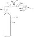
가스 혼합기(600)는 제1 가스 소스(602)와 제2 가스 소스(604)를 포함한다. 본 실시예에서, 가스 소스(602, 604)는 고압 하에서 영구 가스를 저장하도록 배열된 가스 실린더를 포함한다. 각각의 실린더는 제1 실시예에서 개시된 밸브(104)에 유사할 수도 있는 밸브(도시 생략)를 포함한다.The
각각의 가스 실린더 내에 포함된 가스는 상이하고, 요구된 용도에 의존하여 선택된다. 예를 들어, 용접 용례에서, 아르곤과 이산화탄소의 혼합물이 사용된다. 대안적으로, 의료용 용례에서, 산소와 질소의 혼합물이 요구될 수도 있다.The gases contained in each gas cylinder are different and are selected depending on the required application. For example, in a welding application, a mixture of argon and carbon dioxide is used. Alternatively, in a medical application, a mixture of oxygen and nitrogen may be required.
제1 및 제2 가스 소스(602, 604)는 제1 및 제2 공급 라인(606, 608)에 각각 연결된다. 비-리턴 밸브(610, 612)는 가스 소스(602, 604)를 향한 가스의 역류를 방지하기 위해 각각의 제1 및 제2 가스 소스(602, 604)의 하류측에서 제1 및 제2 공급 라인에 각각 배치된다.The first and
또한, 주 밸브(614)가 비-리턴 밸브(610)의 하류측에서 제1 공급 라인(606)에 배치된다. 주 밸브(614)는 수동으로 작동 가능하고, 임의의 적합한 형태를 취할 수도 있다. 예를 들어, 주 밸브(614)는 간단한 온/오프 밸브의 형태를 취할 수도 있고, 또는 조정 가능한 유동 밸브, VIPR 또는 레귤레이터를 포함할 수도 있다. 대안적으로, 주 밸브(614)는 가스 혼합기(600)로부터 원격으로 사용자에 의해 전자식으로 제어될 수도 있다. 가스의 혼합물의 전체 유량(이하에 설명됨)은 주 밸브(614)에 의해 설정된다.A
솔레노이드 밸브(616)가 비-리턴 밸브(612)의 하류측에서 제2 공급 라인(608) 내에 배치된다. 솔레노이드 밸브(616)는 솔레노이드 밸브(616)의 본체 내에 배치된 코일의 세트(도시 생략)를 통해 전류에 응답하여 이동 가능한 전기자(도시 생략)를 포함한다. 전기자는 솔레노이드 밸브(616)를 지나 그 하류측의 구성 요소들로 가스가 유동할 수 있게 하기 위해 솔레노이드 밸브(616)를 개방하거나 폐쇄하도록 이동 가능하다.A
솔레노이드 밸브(616)는 상시 개방 조건에 있을 수도 있다. 달리 말하면, 솔레노이드 밸브(616)를 통한 전류의 부재시에, 전기자는 퇴피 위치에 있어 솔레노이드 밸브(616)가 개방되게 되는 데, 즉 제2 가스 소스(604)로부터의 가스가 그를 통해 솔레노이드 밸브(616)의 하류측의 구성 요소들에 유동하는 것이 가능하다. 전류가 솔레노이드 밸브(616)에 인가되면, 전기자는 퇴피될 것이고 솔레노이드 밸브(616)는 폐쇄되어, 가스가 그를 통해 유동하는 것을 방지할 것이다. 본 실시예에서, 솔레노이드 밸브(616)는 선형 방향에서 연속적으로 변경 가능하다.The
당 기술 분야의 숙련자는 본 발명과 함께 사용될 수 있는 상이한 유형의 솔레노이드 밸브를 즉시 인식할 수 있을 것이다. 예를 들어, 전기자는 선택적으로-작동 가능한 유동 제한부로서 직접 작용할 수도 있다. 대안적으로, 전기자는 다이어프램 상에 직접 작용할 수 있다. 다른 대안으로서, 전기자는 다이어프램의 이동을 조절하기 위해 솔레노이드 밸브(616)의 하류측의 공급 라인(608)과 통신하는 좁은 도관을 통한 유동을 제어할 수 있다. 이러한 장치는 다이어프램 파일럿 밸브로서 공지되어 있다. 솔레노이드 밸브(616)는 이하에 설명되는 바와 같이 분자량 계량기(500)에 의해 제어된다.One of ordinary skill in the art will readily recognize the different types of solenoid valves that may be used with the present invention. For example, the armature may act directly as an optionally-operable flow restriction. Alternatively, the armature may act directly on the diaphragm. Alternatively, the armature may control the flow through the narrow conduit communicating with the
제1 및 제2 공급 라인(606, 608)은 혼합기 유닛(618)에 모두 연결된다. 혼합기 유닛(618)은 제1 및 제2 공급 라인(606, 608)으로부터 2개의 유동을 조합하고, 조합된 유동을 제3 공급 라인(620)으로 통과시키도록 작동 가능하다. 혼합기 유닛(618)은 단지 2개의 유동을 조합하도록 작용하고, 각각의 유동 내의 가스 또는 압력의 비율을 변경하지 않는다.The first and
가스 혼합기(600)는 제4 실시예의 분자량 계량기(500)를 포함한다. 이 구성에서, 분자량 계량기(500)는 그 출력(622)에 인접하여 그 말단부에서 제3 공급 라인(620) 내에 배치된 제1 석영 결정 오실레이터(210)를 포함한다. 출력(622)은 대기로이다. 따라서, 제1 석영 결정 오실레이터(210)에 의해 경험되는 압력은 양호한 근사로 분위기 압력에 대응한다.The
분자량 계량기(500)는 도 5의 실시예에 유사하게, 혼합기(600)의 외부의 분위기 압력에 노출된 제2 석영 결정 오실레이터(510)를 또한 포함한다. 이 경우에, 제2 석영 결정 오실레이터(510)는 출력(622)으로부터의 가스의 유동에 의해 영향을 받지 않은체로 유지하면서 정확한 압력 판독을 보장하도록 출력 부근에(그러나, 출력에는 아님) 배치된다.
게다가, 분자량 계량기(500)는 솔레노이드 밸브(616) 및 분자량 계량기(500)의 센서 조립체(204)에 연결된 제2 전자 솔레노이드 드라이브(652)를 포함한다.
솔레노이드 드라이브(652)는 센서 조립체(204)로부터 신호를 수신하고 그 신호에 응답하여 솔레노이드 밸브(616)를 제어하도록 배열된다. 따라서, 분자량 계량기(500)는 솔레노이드 밸브(616)를 통한 가스의 유동을 제어하도록 작동 가능하다. 달리 말하면, 분자량 계량기(500) 및 솔레노이드 밸브(616)는 제2 공급 라인(608)을 따라 혼합기(618)로의 가스의 유동의 정밀한 원격 압력 조절을 허용하는 피드백 루프를 형성한다. 따라서, 혼합기 유닛(618) 내에서 혼합된 가스의 비율이 이하에 설명되는 바와 같이 정밀하게 제어될 수 있다.A
솔레노이드 드라이브(652)는 솔레노이드 밸브(616)를 제어하기 위한 임의의 적합한 구동 회로를 포함할 수도 있다. 일 적합한 회로는 센서 조립체(204)로부터 연산 증폭기의 네거티브 단자로의 입력을 갖는 연산 증폭기 장치일 수도 있다. 따라서, 가변 저항기가 포지티브 단자에 부착될 수 있다. 가변 저항기는 일정한 기준 레벨을 제공하고 비교기로서 작용하도록 배열될 수도 있다. 기준 레벨은 자동으로 또는 수동으로 변경될 수도 있다.The
센서 조립체(204)로부터 솔레노이드 드라이브(652)로의 입력은 솔레노이드 밸브(616)의 작동을 야기할 것이다. 예를 들어, 센서 조립체(204)[또는, 대안적으로, 프로세서(230)]로부터의 입력 신호가 특정 임계 레벨을 초과하면, 솔레노이드 드라이브(652)는 솔레노이드 밸브(616)를 여기할 수도 있다. 솔레노이드 밸브(616)는 DC 전압이 최대값과 최소값 사이에서 변경되는 디지털(즉, 온 또는 오프) 방식으로 제어될 수도 있다. 대안적으로, 솔레노이드 드라이브(652)로부터의 DC 전압은 솔레노이드 밸브(616)를 통한 유동 제한량을 정확하게 조정하도록 연속적으로 변경 가능할 수도 있다.The input from the
부가적으로 또는 대안적으로, 솔레노이드 드라이브(652)는 AC 부품을 포함하는 DC 출력에 의해 솔레노이드 밸브(616)를 제어할 수도 있다. 솔레노이드 밸브(616)로부터의 전기자의 연장은 인가된 전류에 대략 비례하기 때문에, 이는 솔레노이드 밸브(616)의 전기자가 발진하게 한다. 이러한 발진은 전기자의 정지마찰(stiction)을 완화하는 데, 즉 전기자가 고정되거나 재밍(jamming)되는 것을 방지하는 것을 보조한다.Additionally or alternatively, the
대안적으로, FET, 프로세서 또는 ASIC과 같은 다른 제어 장치가 솔레노이드 밸브(616)의 작동을 제어하기 위해 적절하게 사용될 수도 있다. 또한, 솔레노이드 밸브(616)는 전기자 등의 정확한 이동을 가능하게 하기 위해 디지털(즉, 온/오프) 또는 아날로그(즉, 연속적으로 변경 가능함) 모드에서 작동할 수도 있다.Alternatively, other control devices, such as FETs, processors, or ASICs, may be used as appropriate to control the operation of
도 16에서, 분자량 계량기(500)의 주 구성 요소는 솔레노이드 밸브(616)로부터 개별적으로 도시되어 있다. 이러한 상황에서, 솔레노이드 밸브(616)는 센서 조립체(204)와 솔레노이드 밸브(652) 사이의 무선 통신에 의해 원격으로 제어될 수도 있다.In FIG. 16, the main components of the
가스 혼합기(600)의 작동이 이제 설명될 것이다. 전술된 바와 같이, 분자량 계량기(500)는 가스의 분자량 또는 가스의 평균 분자량을 결정하는 것이 가능하다. 2개의 가스가 상이한 비율로 혼합될 때, 가스 혼합물의 평균 분자량은 각각의 가스의 상대 비율에 따라 변할 것이다. 따라서, 혼합물의 평균 분자량의 측정을 행함으로써, 그리고 각각의 개별 가스의 분자량 및 압력[제2 석영 결정 오실레이터(510)로부터] 및 온도[온도 센서(214)로부터]의 지식을 갖고, 혼합물 내의 각각의 가스의 비율이 결정될 수 있다.Operation of the
제1 가스 소스(602)로부터 가스의 주 유량은 전술된 바와 같이 사용자 조작 가능한 주 밸브(614)에 의해 설정된다. 일단 이것이 설정되어 있으면, 분자량 계량기(500)는 가스의 원하는 비례 혼합물을 성취하기 위해 제2 가스 소스(604)로부터의 정확한 가스량을 분배하기 위해 솔레노이드 밸브(616)를 제어하는 것이 가능하다. 이는 솔레노이드 드라이브(652)를 통해 행해진다.The main flow rate of the gas from the
따라서, 제2 가스 소스(604)로부터의 가스의 비율이 너무 높으면, 분자량 계량기(500)는 솔레노이드 드라이브(652)를 통해, 솔레노이드 밸브(616)를 폐쇄하거나 부분적으로 폐쇄하여 제2 가스 소스(604)로부터 가스의 유동을 제한할 것이다. 부수적으로, 제2 가스 소스(604)로부터의 가스의 비율이 너무 낮으면, 분자량 계량기(500)는 솔레노이드 드라이브(652)를 통해, 솔레노이드 밸브(616)를 개방하거나 부분적으로 개방하여 제2 가스 소스(604)로부터 가스의 유동을 증가시킬 것이다.Thus, if the ratio of the gas from the
상기 실시예는 혼합물 내의 각각의 가스의 비가 신뢰적이고 정확하게 결정되고 유지될 수 있는 가스 혼합물을 제공하는 저비용의 신뢰적이고 강인한 방법을 제공한다.This embodiment provides a low cost, reliable and robust method of providing a gas mixture in which the ratio of each gas in the mixture can be reliably and accurately determined and maintained.
가스 혼합기(700)의 대안 실시예가 도 17에 도시되어 있다. 이전의 실시예의 가스 혼합기(600)는 사용자에 의해 결정된 압력에서 2개의 상이한 가스의 원하는 비례 혼합물을 공급하도록 작동 가능하지만, 가스 혼합기(700)는 2개의 가스의 가스 압력 및 비율의 모두를 전자식으로 제어하도록 작동 가능하다.An alternative embodiment of the
가스 혼합기(700)는 가스 A를 분배하기 위한 제1 가스 소스(702) 및 가스 B를 분배하기 위한 제2 가스 소스(704)를 포함한다. 본 실시예에서, 가스 소스(702, 704)는 고압 하에서 영구 가스를 저장하도록 배열된 가스 실린더를 포함한다. 각각의 실린더는 제1 실시예에서 도시되어 있는 밸브(104)에 유사할 수도 있는 밸브(도시 생략)를 포함한다. 각각의 가스 실린더 내에 포함된 가스 A, B는 상이하고, 도 16의 실시예에 대해 요구된 사용에 의존하여 선택된다.The
제1 및 제2 가스 소스(702, 704)는 제1 및 제2 공급 라인(706, 708)에 각각 연결된다. 비리턴 밸브(710, 712)가 각각의 제1 및 제2 가스 소스(702, 704)의 하류측에서 제1 및 제2 공급 라인에 각각 배치되어 가스 소스(702, 704)를 향한 가스의 역류를 방지한다.The first and
제1 솔레노이드 밸브(714)가 비리턴 밸브(710)의 하류측에서 제1 공급 라인(706)에 배치된다. 제1 솔레노이드 밸브(714)는 제1 솔레노이드 밸브(714)의 본체 내에 위치된 코일의 세트(도시 생략)를 통한 전류에 응답하여 이동 가능한 전기자(도시 생략)를 포함한다. 전기자는 제1 솔레노이드 밸브(714)를 개방하거나 폐쇄하도록 이동 가능하여 가스가 제1 솔레노이드 밸브(714)를 지나 그 하류측의 구성 요소들로 유동하는 것을 가능하게 한다. 가스의 혼합물의 전체 유량(이하에 설명됨)은 이하에 설명되는 바와 같이 솔레노이드 밸브(714)에 의해 설정된다.The
제2 솔레노이드 밸브(716)가 비리턴 밸브(712)의 하류측에서 제2 공급 라인(708)에 배치된다. 솔레노이드 밸브(716)는 제1 솔레노이드 밸브(714)에 실질적으로 유사하고, 가스가 제2 솔레노이드 밸브(716)를 지나 그 하류측의 구성 요소들로 유동하는 것을 가능하게 하기 위해 개방 또는 폐쇄되도록 작동 가능하다.A
제1 및/또는 제2 솔레노이드 밸브(714, 716)는 상시 개방 조건에 있을 수도 있다. 달리 말하면, 제1 및/또는 제2 솔레노이드 밸브(714, 716)를 통한 전류의 부재시에, 전기자는 퇴피 위치에 있어 솔레노이드 밸브(714, 716)가 개방되게 되는 데, 즉 제1 및/또는 제2 가스 소스(702, 704)로부터의 가스가 그를 통해 솔레노이드 밸브(714, 716)의 하류측의 구성 요소들에 유동하는 것이 가능하다. 전류가 솔레노이드 밸브(714, 716)에 인가되면, 전기자는 퇴피될 것이고 솔레노이드 밸브(714, 716)는 폐쇄되어, 가스가 그를 통해 유동하는 것을 방지할 것이다. 본 실시예에서, 솔레노이드 밸브(714, 716)는 선형 방향에서 연속적으로 변경 가능하다.The first and / or
당 기술 분야의 숙련자는 본 발명과 함께 사용될 수 있는 상이한 유형의 솔레노이드 밸브를 즉시 인식할 수 있을 것이다. 예를 들어, 전기자는 선택적으로-작동 가능한 유동 제한부로서 직접 작용할 수도 있다. 대안적으로, 전기자는 다이어프램 상에 직접 작용할 수 있다. 다른 대안으로서, 전기자는 다이어프램의 이동을 조절하기 위해 솔레노이드 밸브(714, 716)의 하류측의 공급 라인(706, 708)과 통신하는 좁은 도관을 통한 유동을 제어할 수 있다. 이러한 장치는 다이어프램 파일럿 밸브로서 공지되어 있다. 솔레노이드 밸브(714, 716)는 이하에 설명되는 바와 같이 분자량 계량기(750)에 의해 제어된다.One of ordinary skill in the art will readily recognize the different types of solenoid valves that may be used with the present invention. For example, the armature may act directly as an optionally-operable flow restriction. Alternatively, the armature may act directly on the diaphragm. Alternatively, the armature may control the flow through the narrow conduit communicating with the
제1 및 제2 공급 라인(706, 708)은 혼합기 유닛(718)에 모두 연결된다. 혼합기 유닛(718)은 제1 및 제2 공급 라인(706, 708)으로부터 2개의 유동(즉, 가스 A 및 가스 B)을 조합하고, 조합된 유동(A와 B의 혼합물)을 제3 공급 라인(720)으로 통과시키도록 작동 가능하다. 혼합기 유닛(718)은 단지 2개의 유동을 조합하도록 작용하고, 각각의 유동 내의 가스 또는 압력의 비율을 변경하지 않는다.The first and
가스 혼합기(700)는 분자량 계량기(750)를 포함한다. 이 구성에서, 분자량 계량기(750)는 전술된 프로세서(230)에 유사한 프로세서(230)에 연결된 제1 센서 조립체(752) 및 제2 센서 조립체(754)를 포함한다.The
제1 센서 조립체(752)는 제1 솔레노이드 밸브(714)의 하류측에서 제1 공급 라인(706) 내에 배치되고 그 내부의 가스 내에 침지된 제1 석영 결정 오실레이터(756)를 포함한다. 제1 센서 조립체(752)는 이전의 실시예들의 구동 회로(212) 및 배터리(216)에 실질적으로 유사한 구동 회로 및 전력 소스(도시 생략)를 또한 포함한다.The
제2 센서 조립체(756)는 혼합기 유닛(718)의 하류측의 공급 라인(720) 내에 배치되고 그 내부의 가스 내에 침지된 제2 석영 결정 오실레이터(758) 및 온도 센서(260)를 포함한다. 제2 센서 조립체(756)는 이전의 실시예들의 구동 회로(212) 및 배터리(216)에 실질적으로 유사한 구동 회로 및 전력 소스(도시 생략)를 또한 포함한다.The
게다가, 분자량 계량기(750)는 솔레노이드 밸브(714) 및 프로세서(230)에 연결된 제1 전자 솔레노이드 드라이브(762)와, 솔레노이드 밸브(716) 및 프로세서(230)에 연결된 제2 전자 솔레노이드 드라이브(764)를 포함한다.
솔레노이드 드라이브(762)는 프로세서(230)로부터 신호를 수신하고 그 신호에 응답하여 솔레노이드 밸브(714)를 제어하도록 배열된다. 동시에, 분자량 계량기(750)는 출구(722)로부터의 총 가스 유출량 또는 대안적으로 출구(722)로부터의 출력 압력을 제어하도록 작동 가능하다. 달리 말하면, 분자량 계량기(750) 및 솔레노이드 밸브(714)는 제1 공급 라인(716)을 따라 혼합기(718)로의 가스의 유동량의 정밀한 원격 압력 조절을 허용하는 피드백 루프를 형성한다.The
솔레노이드 드라이브(764)는 또한 프로세서(230)로부터 신호를 수신하고 그 신호에 응답하여 솔레노이드 밸브(716)를 제어하도록 배열된다. 따라서, 분자량 계량기(750)는 가스 소스(702)로부터의 가스 유동에 대해 가스 소스(704)로부터의 가스 유동의 비율을 제어하도록 작동 가능하다. 달리 말하면, 분자량 계량기(750) 및 솔레노이드 밸브(716)는 제1 공급 라인(706)을 따라 유동하는 가스의 비율에 대해 제2 공급 라인(708)을 따라 혼합기(718)로의 가스의 유동량의 정밀한 원격 조절을 허용하는 피드백 루프를 형성한다. 거기서, 제2 가스 소스(704)로부터의 가스의 요구된 비율은 혼합기 유닛(718) 내에서 혼합된다.The
제2 솔레노이드 드라이브(762, 764)는 각각의 솔레노이드 밸브(714, 716)를 제어하기 위한 임의의 적합한 구동 회로를 포함할 수도 있다. 일 적합한 회로는 센서 조립체(752, 756) 및 프로세서(230)로부터 연산 증폭기의 네거티브 단자로의 입력을 갖는 연산 증폭기 장치일 수도 있다. 따라서, 가변 저항기가 포지티브 단자에 부착될 수 있다. 가변 저항기는 일정한 기준 레벨을 제공하고 비교기로서 작용하도록 배열될 수도 있다. 기준 레벨은 자동으로 또는 수동으로 변경될 수도 있다.The
프로세서(230)로부터 솔레노이드 드라이브(762, 764)로의 입력은 솔레노이드 밸브(714, 716)의 작동을 야기할 것이다. 예를 들어, 프로세서(230)로부터의 입력 신호가 특정 임계 레벨을 초과하면, 솔레노이드 드라이브(762) 또는 솔레노이드 드라이브(764)는 각각의 솔레노이드 밸브(714, 716)를 여기할 수도 있다. 솔레노이드 밸브(714, 716)는 DC 전압이 최대값과 최소값 사이에서 변경되는 디지털(즉, 온 또는 오프) 방식으로 제어될 수도 있다. 대안적으로, 솔레노이드 드라이브(762, 764)로부터의 DC 전압은 각각의 솔레노이드 밸브(714, 716)를 통한 유동 제한량을 정확하게 조정하도록 연속적으로 변경 가능할 수도 있다.Inputs from the
부가적으로 또는 대안적으로, 솔레노이드 드라이브(652)는 이전의 실시예와 관련하여 설명된 바와 같은 AC 부품을 포함하는 DC 출력에 의해 솔레노이드 밸브(616)를 제어할 수도 있다.Additionally or alternatively, the
대안적으로, FET, 프로세서 또는 ASIC과 같은 다른 제어 장치가 솔레노이드 밸브(714, 716)의 작동을 제어하기 위해 적절하게 사용될 수도 있다. 또한, 솔레노이드 밸브(714, 716)는 전기자 등의 정확한 이동을 가능하게 하기 위해 디지털(즉, 온/오프) 또는 아날로그(즉, 연속적으로 변경 가능함) 모드에서 작동할 수도 있다.Alternatively, other control devices such as FETs, processors, or ASICs may be suitably used to control the operation of the
도 17에서, 분자량 계량기(750)의 주 구성 요소는 솔레노이드 밸브(714, 716)로부터 개별적으로 도시되어 있다. 이러한 상황에서, 솔레노이드 밸브(714, 716)는 프로세서(230)와 솔레노이드 밸브(714, 716) 사이의 무선 통신에 의해 원격으로 제어될 수도 있다.In Figure 17, the main components of the
가스 혼합기(700)의 작동이 이제 설명될 것이다. 전술된 바와 같이, 분자량 계량기(750)는 가스 A 및 B의 혼합물의 평균 분자량을 결정하는 것이 가능하다. 게다가, 분자량 계량기(750)는 가스 압력을 결정하도록 작동 가능하다. 2개의 가스가 상이한 비율로 혼합될 때, 가스 혼합물의 평균 분자량은 각각의 가스의 상대 비율에 따라 변할 것이다. 따라서, 혼합물의 평균 분자량의 측정을 행함으로써, 그리고 각각의 개별 가스의 분자량 및 압력 및 온도의 지식을 갖고, 혼합물 내의 각각의 가스의 비율은 원하는 압력 출력과 함께 결정될 수 있다.Operation of the
제1 가스 소스(702)로부터 가스 A의 주 유량은 사용자에 의해 설정되고 또는 자동으로 설정될 수도 있다. 이는 프로세서(230) 내의 설정점을 결정한다. 제1 가스 소스(702)로부터의 가스 A는 주가스이고, 제2 가스 소스(704)로부터의 가스 B는 부가스인 것으로 가정된다.The main flow rate of the gas A from the
센서 조립체(752)는 솔레노이드 밸브(714)의 하류측의 압력(P)을 계산하는 데 사용된다. 제1 가스 소스의 분자량(MWA)이 알려져 있기 때문에[가스 소스(702)로부터의 제1 가스 A가 포장용 가스(packaged gas)이기 때문에], 솔레노이드 밸브(714)의 바로 하류측의 압력이 이어서 식 10)으로부터 결정될 수 있다.The

여기서, P는 압력이고, R은 가스 상수이고, T는 절대 온도[온도 센서(760)에 의해 측정된 바와 같은]이고, MWA는 제1 가스 소스(702)로부터 가스 A의 분자량이고, ρA는 제1 공급 라인(706) 내의 솔레노이드 밸브(714)의 바로 하류측의 측정된 밀도이다.Where P is the pressure, R is the gas constant, T is the absolute temperature (as measured by the temperature sensor 760), MWA is the molecular weight of gas A from the
제1 공급 라인(706) 내에 측정된 바와 같은 압력은 혼합기 유닛(718) 내의 그리고 출력 공급 라인(720) 내의 압력과 대략적으로 동일하다는 가정이 이루어진다. 이 가정은 제2 가스 소스(704)로부터의 가스의 비율이 제1 가스 소스(702)로부터의 주가스에 비교할 때 소량이면 적용된다.It is assumed that the pressure as measured in the
센서 조립체(752)에 의해 측정된 바와 같은 P의 측정된 값은 이어서 원하는 출력 압력을 성취하기 위해 그에 의존하여 솔레노이드 밸브(714)를 제어하도록 작동 가능한 프로세서(230)에 입력된다. 이는 측정된 압력값으로부터 감산된 프로세서(230)에 의해 저장된 설정점 압력 및 솔레노이드 밸브를 제어하는 데 사용된 차이를 갖고 비례 기초로 행해질 수도 있다.The measured value of P, as measured by
다음에, 제3 공급 라인(720) 내의 가스 혼합물의 평균 분자량이 센서 조립체(754)에 의해 결정된다. 본 실시예에서, 제2 석영 결정 오실레이터(758)는 제3 공급 라인(720) 내의 가스 혼합물의 밀도(ρmix)를 결정하도록 작동 가능하다. 가스 혼합물의 평균 분자량(MWmix)은 이어서 식 11)로부터 결정될 수 있다.Next, the average molecular weight of the gas mixture in the

여기서, P는 제1 센서 조립체(752)에 의해 측정된 바와 같은 압력이다. 일단 가스 혼합물의 평균 분자량(MWmix)이 계산되면, 제2 가스 소스(704)로부터의 부가스(B)의 체적 퍼센트(%B)는 식 12)에 따라 결정될 수 있다.Where P is the pressure as measured by the

이는 이어서 식 13)을 제공한다.This in turn provides Equation 13).

가스 B의 체적 퍼센트(%B)의 값은 이어서 프로세서(230)에 의해 원하는 설정점값에 비교될 수 있고 솔레노이드 밸브(716)는 이에 따라 제어된다. 따라서, 분자량 계량기(750)는 가스 A 및 B의 원하는 비례 혼합물을 성취하기 위해 제2 가스 소스(704)로부터 가스 B의 정확한 양을 분배하기 위해 솔레노이드 밸브(716)를 제어하는 것이 가능하다. 이는 솔레노이드 드라이브(764)를 통해 행해진다.The value of the volume percent (% B) of gas B can then be compared to the desired setpoint value by the
따라서, 제2 가스 소스(704)로부터 가스 B의 비율이 너무 높으면, 분자량 계량기(750)는 솔레노이드 드라이브(764)를 통해, 솔레노이드 밸브(716)를 폐쇄하거나 부분적으로 폐쇄하여 제2 가스 소스(704)로부터 가스 B의 유동을 제한할 것이다. 부수적으로, 제2 가스 소스(704)로부터의 가스의 비율이 너무 낮으면, 분자량 계량기(750)는 솔레노이드 밸브(754)를 통해, 솔레노이드 밸브(716)를 개방하거나 부분적으로 개방하여 제2 가스 소스(704)로부터 가스의 유동을 증가시킬 것이다.Thus, if the ratio of gas B from the
상기 실시예는 소정의 압력에서, 즉 혼합물 내의 각각의 가스의 비가 신뢰적이고 정확하게 유지될 수 있는 가스의 일정한 압력에서 가스의 정확한 혼합물을 제공하는 저비용의 신뢰적이고 강인한 방법을 제공한다.This embodiment provides a low cost, reliable and robust method of providing an accurate mixture of gases at a given pressure, i. E., At a constant pressure of the gas where the ratio of each gas in the mixture can be reliably and accurately maintained.
가스 혼합기(800)의 대안적인 실시예가 도 18에 도시되어 있다. 가스 혼합기(800)는 이전의 실시예의 가스 혼합기(700)와 공통인 2개의 가스의 비율과 가스 압력의 모두를 전자식으로 제어하도록 작동 가능하다. 가스 혼합기(700)와 공통인 가스 혼합기(800)의 특징은 동일한 도면 부호가 배정되어 있고, 여기서 더 이상 설명되지 않을 것이다.An alternative embodiment of the
가스 혼합기(800)는 분자량 계량기(850)를 포함한다. 이 구성에서, 분자량 계량기(850)는 제1 센서 조립체(752), 제2 센서 조립체(754) 및 제3 센서 조립체(852)를 포함한다. 각각의 센서 조립체(752, 754, 852)는 프로세서(230)에 연결된다. 제1 및 제2 센서 조립체(752, 754)는 가스 혼합기(700)의 것들과 동일하고, 여기서 더 설명되지 않을 것이다.The
제3 센서 조립체(852)는 제2 솔레노이드 밸브(716)의 하류측에서 제2 공급 라인(708) 내에 배치되고 그 내부의 가스 내에 침지된 제3 석영 결정 오실레이터(856)를 포함한다. 제3 센서 조립체(852)는 이전의 실시예들의 구동 회로(212) 및 배터리(216)에 실질적으로 유사한 구동 회로 및 전력 소스(도시 생략)를 또한 포함한다.The
가스 혼합기(800)의 작동이 이에 설명될 것이다. 전술된 바와 같이, 분자량 계량기(850)는 가스 A와 B의 혼합물의 평균 분자량을 결정하는 것이 가능하다. 게다가, 분자량 계량기(850)는 가스 압력을 결정하도록 작동 가능하다. 2개의 가스가 상이한 비율로 혼합될 때, 가스 혼합물의 평균 분자량은 각각의 가스의 상대 비율에 따라 변경할 것이다. 따라서, 혼합물의 평균 분자량의 측정을 행함으로써, 그리고 각각의 개별 가스의 분자량 및 압력 및 온도의 지식을 갖고, 혼합물 내의 각각의 가스의 비율은 원하는 압력 출력과 함께 결정될 수 있다.The operation of the
제1 가스 소스(702)로부터 가스 A의 주 유량은 사용자에 의해 설정되고 또는 자동으로 설정될 수도 있다. 이는 프로세서(230) 내의 설정점을 결정한다. 제1 가스 소스(702)로부터의 가스 A는 주가스이고, 제2 가스 소스(704)로부터의 가스 B는 부가스인 것으로 가정된다.The main flow rate of the gas A from the
센서 조립체(852)는 제2 공급 라인(708) 내의 솔레노이드 밸브(716)의 하류측의 압력(P)을 계산하는 데 사용된다. 가스 B의 분자량(MWB)이 알려져 있기 때문에[가스 소스(704)로부터의 가스 B가 포장용 가스이기 때문에], 솔레노이드 밸브(716)의 바로 하류측의 압력이 이어서 식 14)로부터 결정될 수 있다.The

여기서, P는 압력이고, R은 가스 상수이고, T는 절대 온도[온도 센서(760)에 의해 측정된 바와 같은]이고, MWB는 제2 가스 소스(704)로부터 가스 B의 분자량이고, ρB는 제2 공급 라인(708) 내의 솔레노이드 밸브(716)의 바로 하류측의 측정된 밀도이다.Where P is the pressure, R is the gas constant, T is the absolute temperature (as measured by the temperature sensor 760), MWB is the molecular weight of the gas B from the
이 값은 센서 조립체(752)를 사용하여 식 9)에서 행해진 계산을 대신하여 사용될 수 있다. 대안적으로, 양 압력이 측정될 수 있고 식 15)에 설명된 바와 같은 혼합기 유닛(718)의 하류측의 압력의 더 양호한 추정을 얻기 위해 평균이 취해진다.This value can be used in place of the calculation performed in equation 9) using the

센서 조립체(752) 및 센서 조립체(852)에 의해 측정된 바와 같은 P의 측정된 값은 이어서 원하는 출력 압력을 성취하기 위해 그에 의존하여 솔레노이드 밸브(714)를 제어하도록 작동 가능한 프로세서(230)에 입력된다. 이는 측정된 압력(P)과 프로세서(230)에 의해 저장된 설정점 사이의 차이의 시간에 대해 적분 및/또는 미분이 선택적 포함을 갖고 비례 기초로 행해질 수도 있다.The measured value of P as measured by
다음에, 제3 공급 라인(720) 내의 가스 혼합물의 평균 분자량이 상기에서 얻어진 P의 값을 사용하여 센서 조립체(754)에 의해 결정된다. 본 실시예에서, 제2 석영 결정 오실레이터(758)는 제3 공급 라인(720) 내의 가스 혼합물의 밀도(ρmix)를 결정하도록 작동 가능하다. 가스 혼합물의 평균 분자량(MWmix)은 이어서 상기 식 10)으로부터 결정될 수 있고, 제2 가스 소스(704)로부터 부가스(B)의 체적 퍼센트(%B)가 상기 식 12) 및 13)에 따라 결정될 수 있다.Next, the average molecular weight of the gas mixture in the
대안적으로, 가스 B의 체적 퍼센트(%B)의 값이 식 16)에 따라 측정된 밀도를 사용하여 계산될 수 있다.Alternatively, the value of the volume percent (% B) of gas B can be calculated using the density measured according to equation (16).

게다가, 식 17)로부터 요구되면 혼합기의 하류측의 압력이 계산될 수 있고,Furthermore, the pressure on the downstream side of the mixer can be calculated if required from equation (17)

여기서, MWmix는 상기 식 12)로부터 결정된다.Here, MWmix is determined from the above equation (12).
상기 실시예는 소정의 압력에서, 즉 혼합물 내의 각각의 가스의 비가 신뢰적이고 정확하게 유지될 수 있는 가스의 일정한 압력에서 가스의 정확한 혼합물을 제공하는 저비용의 신뢰적이고 강인한 방법을 제공한다.This embodiment provides a low cost, reliable and robust method of providing an accurate mixture of gases at a given pressure, i. E., At a constant pressure of the gas where the ratio of each gas in the mixture can be reliably and accurately maintained.
가스 혼합기(900)의 대안적인 실시예가 도 19에 도시되어 있다. 가스 혼합기(900)는 이전의 실시예의 가스 혼합기(600, 700, 800)와 공통인 2개의 가스의 비율을 전자식으로 제어하도록 작동 가능하다. 그러나, 이전의 실시예들의 가스 혼합기(700, 800)에 대조적으로, 가스 혼합기(900)는 출구(722)로부터 가스의 질량 유량을 전자식으로 제어하도록 작동 가능하다. 가스 혼합기(700, 800)와 공통인 가스 혼합기(900)의 특징은 동일한 도면 부호가 배정되어 있고, 여기서 더 이상 설명되지 않을 것이다.An alternative embodiment of the
가스 혼합기(900)는 분자량 계량기(950)를 포함한다. 이 구성에서, 분자량 계량기(950)는 제1 센서 조립체(752) 및 질량 유동 조립체(952)를 포함한다. 각각의 조립체(752, 952)는 프로세서(230)에 연결된다. 제1 센서 조립체(752)는 가스 혼합기(700, 800)의 것들과 동일하고, 여기서 더 설명되지 않을 것이다.The
질량 유동 조립체(952)의 실시예가 도 20에 도시되어 있다. 질량 유동 조립체(952)의 다른 실시예가 도 21에 도시되어 있다.An embodiment of
먼저, 도 20의 질량 유동 조립체(952)를 참조하면, 질량 유동 조립체(952)는 본체(954) 및 센서 조립체(956)를 포함한다. 세서 조립체(956)는 이전의 실시예들의 센서 조립체들과 실질적으로 유사하고, 동일한 도면 부호가 그를 위해 사용된다.First, referring to
본체(954)는 임의의 적합한 재료, 예를 들어 강, 알루미늄 또는 복합재를 포함할 수도 있다. 본체(954)는 도관(958) 및 하우징(960)을 포함한다. 도관(958)은 공급 파이프(720)(도 19)의 내부와 연통하고, 그에 연결하도록 배열된다. 도관(958)은 출구(722)와 공급 파이프(720) 사이에 연통 경로를 제공한다.The
오리피스 플레이트(962)는 도관(958)의 내부 내에 배치된다. 오리피스 플레이트(962)는 제한된 오리피스(964)를 경계 한정하는 벽을 포함한다. 오리피스 플레이트(962)는 도관(958) 내에 유동 제한부를 형성한다. 오리피스(964)는 이하에 설명되는 바와 같이, 오리피스(964)를 통한 유속이 초크 조건(choked condition)에 있도록 도관(958)의 단면적에 대해 작은 단면적(A)을 갖는다.The
오리피스(962)는 도 20에 얇은벽 플레이트로서 도시되어 있지만, 이는 필수적인 것은 아니다. 오리피스 플레이트(962)는 임의의 적합한 벽의 형태를 취할 수도 있고, 테이퍼링 프로파일을 가질 수도 있고, 또는 도시된 것보다 더 큰 두께를 가질 수도 있다. 대안적으로, 임의의 적합한 유동 제한부가 오리피스 플레이트(962) 대신에 사용될 수도 있다. 예를 들어, 유동 제한부는 그 나머지보다 좁은 직경의 튜브의 부분을 포함할 수도 있다. 당 기술 분야의 숙련자는 사용시에 초크 유동이 그를 통해 발생하는 유동 제한 오리피스(964)를 제공하는 데 사용될 수도 있는 대안적인 유동 제한부를 즉시 인식할 수 있을 것이다.The
본 실시예에서, 도관(958)은 수 센티미터의 정도의 길이를 갖는다. 오리피스(962)는 0.1 mm 내지 4 mm의 범위의 직경을 갖는 오리피스(964)를 경계 한정한다. 이는 초크 유동 조건을 제공하고, 질소 또는 아르곤과 같은 가스에 대해 1 l 내지 40 리터/분의 오리피스(964)를 통한 가스의 유량을 공급하는 데 충분하다. 더 저분자량을 갖는 가스의 혼합물에 대해, 오리피스(964)의 직경은 유사한 유량을 성취하도록 축소될 수 있다. 대안적으로, 더 큰 유량에 대해, 오리피스(964)는 상류측 압력이 오리피스(964)를 통한 초크 유동 조건을 생성하기 위해 하류측 압력보다 충분히 높으면, 이에 따라 확장될 수 있다.In this embodiment, the
오리피스 플레이트(962)는 도관(958)의 내부를 오리피스 플레이트(962)의 상류측의 상류측 섹션(966)과 오리피스 플레이트(962)의 하류측의 하류측 섹션(968)으로 분할한다. 사용시에, 가스가 공급 파이프(720)로부터 도관(958)의 상류측 부분(966) 내로 유동할 때, 오리피스 플레이트(962)는 유동 제한부로서 작용하여, 도관(958)의 상류측 부분(966)과 하류측 부분(966) 사이에 압력차를 야기할 것이다. 따라서, 도관(958)의 상류측 부분(966)은 제1 압력(P1) 및 밀도(ρ1)에 있고, 도관의 하류측 부분(968)은 제2(및 사용시에, 더 낮은) 압력(P2) 및 밀도(ρ2)에 있다. 이는 이하에 상세히 설명될 것이다.The
하우징(960)은 도관(958)의 상류측 부분(966)에 인접하여 배치되고, 센서 조립체(956)의 적어도 일부를 포함하도록 배열된다. 하우징(960)의 내부는 분위기 압력에 있을 수도 있고 또는 도관(958)의 내부와 연통하여 및 따라서 공급 라인(720)의 내부와 동일한 압력에 있을 수도 있다. 이는 하우징(960)과 도관(958)의 내부 사이의 압력 피드스루(feed-through)를 위한 요구를 제거할 것이다.The
대안적으로, 하우징(960)은 도관(958)의 부분으로서 제공될 수 있다. 예를 들어, 도관(958)의 부분은 센서 조립체(956)를 수용하도록 확장될 수 있다.Alternatively, the
질량 유동 조립체(954)는 오리피스(964)를 통해 통과하는 가스의 질량 유량을 측정하도록 배열된다. 이 가스는 센서 조립체(956)에 의해 측정된다. 센서 조립체(956)는 이전의 실시예들에서 설명된 바와 같은 구동 회로(212)에 연결된 석영 결정 오실레이터(210), 온도 센서(214) 및 배터리(216)를 포함한다.
본 실시예에서, 석영 결정 오실레이터(210) 및 온도 센서(222)는 도관(958)의 상류측 부분(966)의 내부와 연통하여 배치되고, 반면에 센서 조립체(956)의 나머지 구성 요소들은 하우징(960) 내에 배치된다. 달리 말하면, 석영 결정 오실레이터(210)는 오리피스 플레이트(962)의 상류측에서 가스 내에 침지된다.The
일단 밀도값이 석영 결정 오실레이터(210)로부터 얻어지면, 오리피스(964)를 통한 가스의 질량 유량은 프로세서(230)에 의해 결정될 수 있다. 오리피스를 통한 질량 유량(Q)은 이하와 같이 정의된다.Once the density value is obtained from the

여기서, k는 상수이고, v는 가스의 속도이고, ρ1은 가스의 상류측 밀도이고, A는 오리피스 A의 단면적이다. 그러나, 베르누이 식 19)로부터,Where k is a constant, v is the velocity of the gas, ρ1 is the upstream density of the gas, and A is the cross-sectional area of the orifice A. However, from Bernoulli equation 19)

이다. 오리피스의 단면적이 감소함에 따라, 가스의 속도가 증가할 것이고, 가스의 압력이 감소될 것이다.to be. As the cross-sectional area of the orifice decreases, the velocity of the gas will increase and the pressure of the gas will decrease.
오리피스(964)를 통한 질량 유량의 결정은 "초크" 또는 "임계" 유동으로서 공지되어 있는 조건에 의존한다. 이러한 상황은 가스 속도가 음속 조건에 도달할 때, 즉 오리피스 플레이트(962)에 의해 발생된 유동 제한부가 오리피스(964)를 통해 유동하는 가스의 속도가 음속에 도달되도록 할 때 발생한다. 이는 오리피스(964)를 가로지르는 압력비(즉, P1/P2)가 대략 2 이상일 때 발생한다. 대안적인 수단으로서, 이 조건은 상류측 절대 압력(P1)이 하류측 절대 압력(P2)보다 적어도 0.5 내지 1 bar 더 높을 때 일반적으로 적용 가능하다.The determination of the mass flow rate through the
일단 이 조건이 부합되면, 오리피스(964)를 통한 공기의 속도의 매우 적은 추가의 증가가 존재한다. 따라서, v = c(당해의 가스에서 음속)인 초크 유동 조건에, 식 18)은 이하와 같이 된다.Once this condition is met, there is a very small additional increase in air velocity through

따라서, 고정된 단면적(A)을 갖는 오리피스에 대해, 오리피스(964)를 통한 질량 유동은 상류측 밀도에만 의존한다. 이는 석영 결정 오실레이터(210)가 측정을 위해 배열되는 파라미터이다.Thus, for an orifice with a fixed cross-sectional area A, the mass flow through the
도 22는 질량 유량 측정의 실험 데이터를 도시하고 있다. 도 22는 질소 가스에 대해 X-축 상의 가스 유량(리터/분의 단위)의 함수로서 Y-축 상이 공진 주파수(kHz 단위)의 그래프이다. 도시되어 있는 바와 같이, 그래프는 매우 선형이고, 질량 유량이 석영 결정 오실레이터(210)를 사용하여 정확하게 측정될 수 있는 것을 도시하고 있다.Figure 22 shows experimental data of mass flow measurement. 22 is a graph of the resonance frequency (in kHz) of the Y-axis as a function of gas flow rate (unit of liters / minute) on the X-axis with respect to nitrogen gas. As shown, the graph is very linear and shows that the mass flow rate can be accurately measured using a
또한, 석영 결정 오실레이터(210)의 높은 정확도는 측정이 백만분율의 분해능을 갖는 매우 높은 정확도로 가능하게 한다. 높은 밀도 및 압력에서 석영 밀도 센서(210)의 선형 응답과 결합하여, 높은 정확도는 H2 및 He와 같은 매우 가벼운 가스의 질량 유량이 정확하게 측정되는 것을 가능하게 한다.In addition, the high accuracy of the
그러나, 전술된 바와 같이, 석영 결정 오실레이터(210)를 사용하는 질량 유동 측정은 단지 초크 유동 조건 하에서, 즉 오리피스(964)를 통한 유동의 속도가 가스 내의 음속에 근접하거나 동일할 때 정확할 것이다. 이는 실제로, 정확한 측정을 제공하기 위해 사용자가 공급 라인(720)을 통한 특정 최소 가스 유동을 유지하도록 요구한다.However, as discussed above, the mass flow measurement using the
그 결과, 단독으로 작동하는 단일의 상류측 석영 결정 오실레이터(210)는 초크 유동 조건이 오리피스(964)를 통해 존재하는지 여부의 지시를 제공하는 것이 불가능하다. 도 21의 실시예는 이 양태를 처리하도록 작동 가능하다.As a result, the single upstream
도 21의 질량 유동 조립체(952)에서, 다른 석영 결정 오실레이터(972)를 포함하는 다른 센서 조립체(970)가 제공된다. 오리피스(964)의 상류측 및 하류측의 모두에서의 압전 센서의 사용은 정확한 유동 계량이 성취되는 것을 가능하게 한다.In the
식 19)와 관련하여 전술된 바와 같이, 질량 유량(Q)은 오리피스(964)를 통한 유체 유동의 속도가 음속이거나 음속에 접근하면 상류측 밀도(ρ1)에 비례한다. 전술된 바와 같이, 이 조건은 상류측 압력 대 하류측 압력의 비(즉, P1/P2)가 대략 2 이상이면 일반적으로 부합된다.The mass flow rate Q is proportional to the upstream density?1 as the velocity of the fluid flow through the
그러나, 실제로, 압력비는 불충분할 수도 있다. 베르누이의 식 및 초크 유동 및 음속의 설정된 이론의 적용은 식 21)을 유도하고,However, in practice, the pressure ratio may be insufficient. The application of the Bernoulli equation and set theories of choke flow and sound speed leads to equation (21)

여기서, k'는 무차원 상수이고, A는 오리피스 면적이고, ρ1은 상류측 밀도이고, ρ2는 하류측 밀도이다.Where k 'is a dimensionless constant, A is the orifice area, ρ1 is the upstream density, and ρ2 is the downstream density.
명백하게, ρ1/ρ2≥2이면, 식 21)은 초크 유동 조건이 오리피스(964)를 가로질러 존재하는 것으로 간주되기 때문에 상기 식 20)에 의해 근사될 수 있다. 따라서, 이 경우에, 단지 제1 센서 조립체(956)로부터의 측정은 ρ1/ρ2≥2인 상황에서 질량 유량의 정확한 지시를 제공하는 데 이용될 수 있다.Obviously, if ρ1 / ρ2 ≥2, then Eq. (21) can be approximated by Eq. (20) as the choked flow condition is considered to exist across orifice (964). Thus, in this case, only measurements from the
그러나, 비가 이보다 작으면, 식 18)은 상류측 밀도(ρ1) 및 하류측 밀도(ρ2)를 각각 측정하고 초크 유동 조건 미만의 오리피스(964)를 통한 유량에서 질량 유량을 결정하기 위해 양 센서 조립체(954, 970)를 사용하여 질량 유량을 계산하는 데 이용될 수 있다.However, if the ratio is smaller, Eq. 18) can be used to measure the upstream density (rho1 ) and the downstream density (rho2 ), respectively, and to determine the mass flow rate Can be used to calculate the mass flow rate using the
도 19를 재차 참조하면, 도 20의 질량 유동 조립체(952) 및 도 21의 질량 유동 조립체(952)는 가스 혼합기(900)와 함께 사용될 수 있다.Referring again to FIG. 19,
이제, 가스 혼합기(900)의 작동이 설명될 것이다. 전술된 바와 같이, 분자량 계량기(950)는 가스 A와 B의 혼합물의 평균 분자량을 결정하는 것이 가능하다. 게다가, 분자량 계량기(950)는 출력(722)으로부터 질량 유량을 전자식으로 결정하여 설정하도록 작동 가능하다.Now, the operation of the
2개의 가스가 상이한 비율로 혼합될 때, 가스 혼합물의 평균 분자량은 각각의 가스의 상대 비율에 따라 변할 것이다. 따라서, 혼합물의 평균 분자량의 측정을 행함으로써, 그리고 각각의 개별 가스의 분자량 및 압력 및 온도의 지식을 갖고, 혼합물 내의 각각의 가스의 비율이 원하는 질량 유동 출력과 함께 결정될 수 있다.When the two gases are mixed at different ratios, the average molecular weight of the gas mixture will vary with the relative proportions of the respective gases. Thus, by making a measurement of the average molecular weight of the mixture, and with knowledge of the molecular weight and pressure and temperature of each individual gas, the ratio of each gas in the mixture can be determined with the desired mass flow output.
가스 혼합물의 원하는 질량 유량은 사용자에 의해 설정되거나 자동으로 설정될 수도 있다. 이는 프로세서(230) 내에 설정점을 결정한다. 제1 가스 소스(702)로부터의 가스 A는 주가스이고, 제2 가스 소스(704)로부터의 가스 B는 부가스이다.The desired mass flow rate of the gas mixture may be set by the user or automatically set. Which determines a set point in the
이전의 실시예들과 공통으로, 센서 조립체(752)는 솔레노이드 밸브(714)의 하류측의 압력(P)을 계산하는 데 사용된다. 제1 가스 소스의 분자량(MWA)이 알려져 있기 때문에[가스 소스(702)로부터의 제1 가스 A가 포장용 가스이기 때문에], 솔레노이드 밸브(714)의 바로 하류측의 압력이 이어서 상기 식 10)으로부터 결정될 수 있다.In common with the previous embodiments, the
센서 조립체(752)에 의해 측정된 바와 같은 P의 측정된 값은 이어서 프로세서(230)에 의해 이용된다. 제3 공급 라인(720)의 가스 혼합물의 평균 분자량은 질량 유동 조립체(952)의 부분을 형성하는 센서 조립체(956)에 의해 결정된다. 본 실시예에서, 석영 결정 오실레이터(210)는 이전의 실시예들의 오실레이터(758)와 공통으로, 제3 공급 라인(720) 내의 또는 도관(954)의 상류측 부분(966) 내의 가스 혼합물의 밀도(ρmix)를 결정하도록 작동 가능하다. 가스 혼합물의 평균 분자량(MWmix)은 이어서 상기 식 10)으로부터 프로세서(230)에 의해 결정될 수 있다.The measured value of P, as measured by
식 20)에 따라 질량 유량을 계산하기 위해[여기서, 식 20)에서의 ρ1은 ρmix에 대응함], 이어서 식 22)로부터 가스 혼합물에서 음속을 계산할 필요가 있고,It is necessary to calculate the sound velocity in the gas mixture from equation (22)), and then calculate the mass flow rate according to equation (20) where [rho1 in

여기서, γ는 일정한 압력 및 일정한 체적에서 비열의 비이고(가스에 따라 1.3 내지 1.667 - 이는 예를 들어 주가스에 대해 사용자에 의해 사전 설정될 수 있음), R은 가스 상수이고, T는 오리피스(964) 앞의 혼합물의 절대 온도이다.Where R is the gas constant, and T is the orifice (for example, about 1 to about 1.667, depending on the gas, which can be preset for example by the user for the main gas) 964) is the absolute temperature of the preceding mixture.
유량은 이어서 식 23)에 따라 계산될 수 있다.The flow rate can then be calculated according to equation (23).

유량(Q)의 값은 이어서 이에 따라 질량 유량을 조정하기 위해 밸브(714)에 피드백된 사전 결정된 설정점값 및 차이(비례, 선택적으로 시간에 대해 적분 및/또는 미분을 포함함)와 비교될 수 있다.The value of the flow rate Q can then be compared to a predetermined set point value and a difference (proportional, optionally including integral and / or derivative over time) fed back to the
제2 가스 소스(704)로부터 부가스(B)의 체적 퍼센트(%B)는 상기 식 11) 및 12)에 따라 결정되고 분자량 계량기(950)에 의해 적절하게 조정될 수 있다.The volume percentage (% B) of the negative gas B from the
상기 실시예는 소정 질량 유량에서, 즉 가스의 일정한 질량 유동이 요구되는 경우 그리고 혼합물 내의 각각의 가스의 비가 신뢰적으로 그리고 정확하게 유지될 수 있는 경우에 가스의 정확한 혼합물을 제공하는 저비용의 신뢰적이고 강인한 방법을 제공한다.This embodiment is a low cost, reliable and robust process that provides a precise mixture of gas at a given mass flow rate, i.e. when a constant mass flow of gas is required and when the ratio of each gas in the mixture can be reliably and accurately maintained ≪ / RTI >
가스 혼합기(1000)의 대안 실시예가 도 23에 도시되어 있다. 가스 혼합기(1000)는 이전의 실시예의 가스 혼합기(600, 700, 800, 900)와 공통으로 2개의 가스의 비율을 전자식으로 제어하도록 작동 가능하다.An alternative embodiment of the
도 18의 가스 혼합기(800)와 공통으로, 가스 혼합기(100)는 출구(722)로부터 가스의 질량 유량을 전자식으로 제어하도록 작동 가능하다. 가스 혼합기(700, 800, 900)와 공통인 가스 혼합기(700, 800, 900)의 특징은 동일한 도면 부호가 배정되어 있고, 여기서 더 이상 설명되지 않을 것이다.In common with the
가스 혼합기(1000)는 분자량 계량기(1050)를 포함한다. 이 구성에서, 분자량 계량기(1050)는 도 18의 가스 혼합기(800)의 제1 센서 조립체(752) 및 제2 센서 조립체(754)를 포함한다. 게다가, 분자량 계량기(1050)는 질량 유동 조립체(1052)를 포함한다. 질량 유동 조립체(1052)는 솔레노이드 밸브(714)의 하류측 및 센서 조립체(756)의 상류측에서 제1 공급 라인(706) 내에 배치된다.
각각의 조립체(752, 756, 1052)는 프로세서(230)에 연결된다. 제1 센서 조립체(752) 및 제2 센서 조립체(756)는 가스 혼합기(700, 800)의 것들과 동일하고, 여기서 더 설명되지 않을 것이다. 질량 유동 조립체(1052)는 도 20 또는 도 21에 도시되어 있는 질량 유동 조립체(952)에 실질적으로 유사하다. 어느 하나가 본 구성에 사용될 수도 있다. 구조적 설명을 위해, 본 실시예의 차이점은, 질량 유동 조립체(1052)는 이전의 실시예에서와 같이 그 하류측보다는 혼합기 유닛(718)의 상류측에서 제1 공급 라인(706) 내에 배치된다는 것이다.Each of the
분자량 계량기(1050)의 작동이 이제 설명될 것이다. 본 실시예에서, 질량 유동 조립체(1052)는 석영 밀도 센서(210)가 양 기능을 위해 사용되었던 이전의 실시예에 대조적으로, 분자량 결정에 본질적으로 독립적이다.The operation of the
본 실시예에서, 질량 유동 조립체(1052)는 석영 결정 오실레이터(210)(도 20/도 21)를 사용하여 오리피스(964)의 상류측에서 가스 A의 밀도(ρA)를 먼저 측정하는 데 사용된다. 오리피스(964)의 상류측의 절대 온도는 또한 온도 센서(214)를 사용하여 측정된다. 제1 가스 소스(702)로부터 가스 A의 질량 유량은 이어서 식 22) 및 23)으로부터 결정될 수 있다.In this embodiment, the
유량은 이어서 식 24)에 따라 계산될 수 있고,The flow rate can then be calculated according to equation 24,

여기서here

여기서, γ는 일정한 압력 및 일정한 체적에서 비열의 비이고(가스에 따라 1.3 내지 1.667 - 이는 예를 들어 주가스에 대해 사용자에 의해 사전 설정될 수 있음), R은 가스 상수이고, T는 오리피스(964) 앞의 가스 A의 절대 온도이다.Where R is the gas constant, and T is the orifice (for example, about 1 to about 1.667, depending on the gas, which can be preset for example by the user for the main gas) 964) is the absolute temperature of gas A.
프로세서(230) 내로 입력된 설정점값은 이어서 오리피스(964)를 통한 가스 A의 일정한 유동을 유지하기 위해 솔레노이드 밸브(714)를 제어하는 데 사용될 수 있다. 이 접근법의 사용은, 초크 유동 조건이 단일의 가스, 즉 가스 A에서 발생하기 때문에 가스 혼합물 내의 음속에 대한 어떠한 보정도 요구되지 않는다는 이익을 갖는다.The set point value input into the
질량 유동 조립체(1052)의 하류측의 압력(P)은 이어서 식 26)에 따라 센서 조립체(752)에 의해 결정될 수 있다.The pressure P on the downstream side of

여기서, ρ'A는 센서 조립체(752)의 석영 결정 오실레이터(756)에 의해 측정된 바와 같은 오리피스(964)의 하류측에서의 가스 A의 밀도이다.WhereA 'is the density of gas A on the downstream side of
게다가, 석영 결정 오실레이터(756)는 질량 유동 조립체(1052)의 작동을 체크하고, 요구되면 도 21에 설명된 실시예의 작동에 따른 보정을 제공하는 데 또한 사용될 수 있다.In addition, a
일단 압력(P)이 결정되어 있으면, 혼합물의 평균 분자량 및 %B 값은 이전의 실시예들을 참조하여 설명되고 상기에 열거된 식 11) 내지 13) 및 제2 센서 조립체(754)를 이용하여 결정될 수 있다.Once the pressure P has been determined, the average molecular weight and% B value of the mixture is determined using equations 11) to 13) and the
게다가, 부가의 센서 조립체가 이와 같이 요구되면, 도 18의 실시예의 방식으로 제2 공급 라인(708) 내에 배치될 수 있다.In addition, if additional sensor assemblies are thus desired, they can be placed in the
상기 실시예들의 변형예들이 당 기술 분야의 숙련자에게 명백할 것이다. 하드웨어 및 소프트웨어 부품의 정밀한 구성은 상이할 수도 있고 여전히 본 발명의 범주 내에 있을 수도 있다. 당 기술 분야의 숙련자는 사용될 수 있는 대안적인 구성을 즉시 인식할 수 있을 것이다.Modifications of the above embodiments will be apparent to those skilled in the art. The precise configuration of hardware and software components may be different or may still be within the scope of the present invention. One of ordinary skill in the art will readily recognize alternative configurations that may be used.
예를 들어, 전술된 실시예가 32.768 kHz의 기본 주파수를 갖는 석영 결정 오실레이터를 이용하고 있다. 그러나, 대안적인 주파수에서 작동하는 결정이 사용될 수도 있다. 예를 들어, 60 kHz 및 100 kHz에서 작동하는 석영 결정 오실레이터는 전술된 실시예와 함께 사용될 수도 있다. 상이한 결정에 대한 밀도를 갖는 주파수 변화를 도시하고 있는 그래프가 도 24에 도시되어 있다. 다른 예로서, 1.8 MHz의 주파수에서 작동하는 결정 오실레이터가 사용될 수 있다.For example, the embodiment described above uses a quartz crystal oscillator with a fundamental frequency of 32.768 kHz. However, crystals operating at alternative frequencies may be used. For example, a quartz crystal oscillator operating at 60 kHz and 100 kHz may be used with the embodiments described above. A graph showing frequency changes with densities for different crystals is shown in Fig. As another example, a crystal oscillator operating at a frequency of 1.8 MHz may be used.
더 고주파수 작동은 더 짧은 시간 기간이 주어진 수의 사이클을 샘플링하도록 요구되기 때문에 압력이 더 빈번하게 모니터링되는 것을 가능하게 한다. 부가적으로, 더 고주파수 결정은 결정의 "슬립" 모드에서 더 작은 듀티 사이클이 사용되는 것을 가능하게 한다. 설명으로서, 대부분의 경우에, 결정 및 구동 회로는 대부분의 시간을 스위칭 오프되어 소비할 것이고, 단지 측정이 요구될 때 몇초 동안만 스위칭 온된다. 이는 예를 들어 분당 1회 발생할 수도 있다. 더 고주파수 결정이 사용될 때, 압력은 더 고속으로 측정될 수 있다. 따라서, 결정이 작동하는 시간은 감소될 수 있다. 이는 전력 소비를 감소시키고 부수적으로 배터리 수명을 향상시킬 수도 있다.Higher frequency operation enables the pressure to be monitored more frequently because a shorter time period is required to sample a given number of cycles. Additionally, higher frequency determination enables a smaller duty cycle to be used in the "sleep" mode of crystal. By way of explanation, in most cases, the decision and drive circuit will consume most of the time switched off, and only switch on for a few seconds when measurement is required. This may occur, for example, once per minute. When higher frequency crystals are used, the pressure can be measured at a higher speed. Therefore, the time for the crystal to operate can be reduced. This may reduce power consumption and, incidentally, improve battery life.
부가적으로, 상기 실시예들은 석영 결정 오실레이터의 절대 주파수를 측정함으로써 설명되어 있다. 그러나, 가스 실린더 연계된 레귤레이터에 합체된 자급형 전자 기기에서, 동일한 유형이지만 진공 또는 압력 패키지 내에 봉입된 기준 결정과 그 주파수를 비교함으로써 센서의 주파수의 시프트를 측정하는 것이 유리할 수도 있다. 압력 패키지는 선택된 밀도에서의 가스, 분위기 조건 하에서의 가스를 포함할 수도 있고, 또는 가스 실린더의 외부의 대기로 개방될 수도 있다.Additionally, the above embodiments are illustrated by measuring the absolute frequency of a quartz crystal oscillator. However, it may be advantageous to measure the shift of the frequency of the sensor by comparing the frequency with a reference crystal enclosed in a vacuum or pressure package of the same type, in a self-contained electronic device incorporated in a gas-cylinder connected regulator. The pressure package may include gas at a selected density, gas under ambient conditions, or may be open to the atmosphere outside the gas cylinder.
적합한 센서 조립체(1100)가 도 25에 도시되어 있다. 센서 조립체(1100)는 제1 석영 결정 오실레이터(1102) 및 제2 석영 결정 오실레이터(1104)를 포함한다. 제1 석영 결정 오실레이터(1102)는 진공 하에서 밀봉된 용기(1106) 내에 배치된 기준 결정이다. 제1 석영 결정 오실레이터(1102)는 구동 회로(1108)에 의해 구동된다.A
제2 석영 결정 오실레이터(1104)는 이전의 실시예들에 설명된 결정(210)에 유사한 결정이다. 제2 석영 결정 오실레이터(1104)는 하우징(1106) 내의 가스 환경에 노출된다. 제2 석영 결정 오실레이터(1104)는 구동 회로(1110)에 의해 구동된다.The second
이 비교는 2개의 주파수 신호를 조합하고 2개의 결정 사이의 차이에 동일한 주파수에서 출력을 생성하는 전자 혼합기 회로(1114)를 사용하여 수행될 수도 있다. 이 장치는 예를 들어 온도에 기인하는 작은 변화가 예를 들어 무효화되는 것을 가능하게 한다.This comparison may be performed using an
또한, 센서 조립체(956)에 사용된 회로는 단지 차이 주파수가 측정되도록 요구되기 때문에 간단화될 수 있다. 또한, 이 접근법은 결정 주파수를 직접 측정하기 어려울 수도 있는 고주파수(MHz) 결정 오실레이터와 함께 사용을 위해 특히 적합하다.In addition, the circuitry used in the
부가적으로, 밀도, 질량 또는 질량 유동을 측정하고 표시하도록 요구되는 모든 전자 기기는 가스 실린더 상에 또는 내에 장착될 필요는 없다. 예를 들어, 전자 기능은 영구적으로 실린더 상에 장착된 유닛들과 소비자의 사용 스테이션 상에 장착되거나 또는 통상의 유량계를 위해 일반적으로 사용된 위치와 같은 실린더의 출구 상에 일시적으로 장착된 유닛들 사이에 분할될 수 있다.Additionally, not all electronic devices required to measure and display density, mass or mass flow need to be mounted on or in the gas cylinder. For example, the electronic function may include permanently mounted units on cylinders and between units temporarily mounted on the outlet of a cylinder, such as a position commonly used for a conventional flow meter, Lt; / RTI >
이 장치의 예가 도 26을 참조하여 개시된다. 장치는 가스 실린더(1200), 레귤레이터(1202) 및 분자량 계량기(1204)를 포함하는 가스 실린더 조립체(1200)를 포함한다. 가스 실린더(1200), 레귤레이터(1202) 및 분자량 계량기(1204)는 이전의 실시예들을 참조하여 실질적으로 전술된 바와 같은 가스 실린더(100), 레귤레이터(150) 및 분자량 계량기(200, 300, 400, 500)에 실질적으로 유사하다.An example of this apparatus is disclosed with reference to Fig. The apparatus includes a
본 실시예에서, 분자량 계량기(1204)는 이전의 실시예들의 석영 결정 오실레이터(210) 및 구동 회로(212)에 유사한 석영 결정 오실레이터 및 구동 회로(도시 생략)를 포함한다. 안테나(1206)가 예를 들어 블루투스, 적외선(IR) 또는 RFID와 같은 임의의 적합한 원격 통신 프로토콜을 통한 통신을 위해 제공된다. 대안적으로, 1-와이어 통신이 이용될 수도 있다.In this embodiment, the
다른 대안으로서, 음향 통신 방법이 사용될 수도 있다. 이러한 방법의 장점은 원격 통신이 외부 안테나를 위한 요구 없이 실행될 수 있다는 것이다.Alternatively, an acoustic communication method may be used. An advantage of this method is that telecommunications can be implemented without the need for an external antenna.
연결 파이프(1208)가 가스 실린더(1200)의 출구에 연결된다. 연결 파이프는 신속 연결 연결부(1210)에 의해 종료된다. 신속 연결 연결부(1210)는 연결 배관 또는 부품들이 가스 실린더(1200)로부터 용이하고 신속하게 연결되고 분리되는 것을 가능하게 한다.A connecting
신속 연결 유닛(1250)이 가스 실린더(1200)로의 연결을 위해 제공된다. 상보형 신속 연결 커넥터(1212)가 커넥터(1208)로의 연결을 위해 제공된다. 또한, 신속 연결 유닛(1250)은 데이터 유닛(1252)을 구비한다. 데이터 유닛(552)은 디스플레이(1254)와, 가스 실린더 조립체(120)의 안테나(1204)와 통신을 위한 안테나(1256)를 포함한다. 디스플레이(1254)는 예를 들어 전력 소비를 최소화하고 디스플레이의 가시성을 최대화하기 위한 LCD, LED 또는 일광 판독 가능 디스플레이를 포함할 수도 있다.A
데이터 유닛(1252)은 가스 실린더 조립체(1200)의 센서 조립체(1202)에 의해 측정된 바와 같은 다양한 파라미터를 로그할 수도 있다. 예를 들어, 데이터 유닛(1252)은 분자량 대 시간을 로그할 수 있다. 이러한 로그는 예를 들어, 가스 유동이 존재하였는지를 점검하고 중요한 구성 요소들 상에 장기간의 가스 용접 절차 중에 보정하거나 또는 특정 소비자의 사용량에 대한 회사 데이터를 공급하기를 원하는 용접 계약자에게 유용할 수 있다.The
부가적으로, 데이터 유닛(1250)은 이하의 기능: 가스 유형이 변화하면 가청성 또는 가시성 경보를 제공하기 위한 것, 가스의 유형에 대한 데이터를 포함하고 표시하기 위한 것, 멀티모드 작동, 예를 들어 공급자/필터 모드 및 소비자 모드를 제공하기 위한 것, 데이터의 입력을 허용하는 것, 실린더 상에 요약 형태로 전달될 수 있는 실린더 수, 가스의 유형, 분석의 증명서, 소비자 이력(어느 날짜에 걸쳐 실린더를 가짐), 안전 데이터 및 작동 팁과 같은 데이터를 제공하는 것과 같은 기능을 제공하도록 배열될 수도 있다.In addition, the
대안으로서, 모든 상기 예는 선택적으로, 분자량 계량기(200, 300, 400, 500)의 견지에서 설명된 바와 같이 가스 실린더(100) 또는 하우징(202) 상에(또는 내에) 완전히 배치된 시스템으로부터 처리되고, 저장되거나, 또는 얻어질 수도 있다.Alternatively, all of the above examples may optionally be processed from a system that is completely disposed within (or within) the
상기 예들은 임의의 원하는 비율로 사전 결정된 질량 유량 또는 압력에서 2개의 가스를 혼합하도록 작동 가능한 혼합기 장치를 예시하고 있다. 그러나, 3개 이상의 가스의 혼합을 가능하게 하기 위해 이들 장치를 캐스케이딩하는 것이 가능하다. 예를 들어, 부가의 센서 조립체가 출력(722)에, 그리고 부가의 센서 조립체가 부가의 가스 소스(C)에 추가될 수 있다. 일반적으로, N개의 성분을 갖는 혼합물을 얻기 위해, (2N-1) 센서 조립체를 가질 필요가 있다.The examples illustrate a mixer device operable to mix two gases at a predetermined mass flow rate or pressure at any desired rate. However, it is possible to cascade these devices to enable mixing of three or more gases. For example, an additional sensor assembly may be added to the
상기 실시예는 석영 결정 오실레이터의 사용을 참조하여 설명되었지만, 당 기술 분야의 숙련자는 또한 사용될 수 있는 대안적인 압전 재료들을 즉시 인식할 수 있을 것이다. 예를 들어, 비한정적인 리스트는, 리튬 탄탈레이트, 리튬 니오베이트, 리튬 보레이트, 베리나이트, 갈륨 비소, 리튬 테트라보레이트, 알루미늄 포스페이트, 비스무스 게르마늄 산화물, 다결정질 지르코늄 티타네이트 세라믹, 고-알루미나 세라믹, 실리콘-아연 산화물 복합재료 또는 디포타슘 타르트레이트를 포함하는 결정 오실레이터를 포함할 수도 있다.Although the above embodiments have been described with reference to the use of a quartz crystal oscillator, those skilled in the art will also readily recognize alternative piezoelectric materials that may be used. For example, a non-limiting list includes lithium tantalate, lithium niobate, lithium borate, vernite, gallium arsenide, lithium tetraborate, aluminum phosphate, bismuth germanium oxide, polycrystalline zirconium titanate ceramic, A silicon-zinc oxide composite, or a crystal oscillator including diphosphate tartrate.
본 발명의 실시예들이 도시되어 있는 예를 특히 참조하여 설명되었다. 특정 예가 도면에 도시되어 있고 본 명세서에 상세히 설명되었지만, 도면 및 상세한 설명은 개시되어 있는 특정 형태에 본 발명을 한정하도록 의도되는 것은 아니라는 것이 이해되어야 한다. 본 발명의 범주 내에 설명되어 있는 예에 변형 및 수정이 이루어질 수도 있다는 것이 이해될 수 있을 것이다.Embodiments of the invention have been described with particular reference to the example shown. Although specific examples are shown in the drawings and described in detail herein, it should be understood that the drawings and detailed description are not intended to limit the invention to the particular form disclosed. It will be appreciated that variations and modifications may be made to the examples described within the scope of the present invention.
100: 가스 실린더102: 가스 실린더 본체
104: 밸브106: 개구
108: 하우징110: 출구
112: 밸브체114: 밸브 시트
150: 레귤레이터152: 입구
154: 출구158: 출구 파이프
160: 커플링200: 분자량 계량기100: gas cylinder 102: gas cylinder body
104: valve 106: opening
108: housing 110: outlet
112: valve body 114: valve seat
150: regulator 152: inlet
154: outlet 158: outlet pipe
160: Coupling 200: Molecular weight meter
Claims (14)
Translated fromKorean제1 가스를 공급하기 위한 제1 가스 소스와,
상기 제1 가스와 상이한 제2 가스를 공급하기 위한 제2 가스 소스와,
상기 제1 및 제2 가스 소스로부터 제1 및 제2 가스의 각각의 유동을 조절하기 위한 제1 및 제2 전자 밸브와,
혼합기와,
출구로서, 상기 혼합기는 상기 제1 및 제2 전자 밸브의 하류측에 위치되고, 사용시 제1 가스와 제2 가스를 혼합하여 혼합 가스를 출구에 제공하도록 배열되는 것인 출구와,
계량기를 포함하고,
상기 계량기가,
상기 혼합 가스의 평균 분자량을 결정하도록 작동될 수 있고, 혼합 가스와 접촉되는 고주파수 평면형 압전 결정 오실레이터를 포함하는 제1 센서 조립체,
상기 제1 전자 밸브 또는 제2 전자 밸브 각각의 하류측의 그리고 혼합기의 상류측의 제1 또는 제2 가스의 압력을 결정하도록 작동될 수 있는 제2 센서 조립체, 및
상기 혼합 가스의 평균 분자량 및 상기 가스 압력에 응답하여, 상기 혼합 가스의 제1 및 제2 가스의 상대 비율과, 출구로부터의 혼합 가스의 압력 또는 질량 유량을 제어하기 위해 상기 제1 및 제2 전자 밸브를 자동으로 제어하도록 작동될 수 있는 제어기를 포함하는 것인
가스 혼합기 장치.A gas mixer device comprising:
A first gas source for supplying a first gas,
A second gas source for supplying a second gas different from the first gas,
First and second solenoid valves for regulating respective flows of the first and second gases from the first and second gas sources,
Mixer,
Wherein the mixer is located downstream of the first and second solenoid valves and is arranged to mix a first gas and a second gas in use to provide a mixed gas at an outlet in use,
Including a meter,
Wherein,
A first sensor assembly including a high frequency planar piezoelectric crystal oscillator operable to determine an average molecular weight of the gas mixture and in contact with the gas mixture,
A second sensor assembly operable to determine a pressure of the first or second gas downstream of each of the first solenoid valve or the second solenoid valve and upstream of the mixer,
In order to control the relative ratio of the first and second gases of the mixed gas and the pressure or mass flow rate of the mixed gas from the outlet in response to the average molecular weight of the mixed gas and the gas pressure, And a controller operable to automatically control the valve
Gas mixer device.
상기 가스 혼합기 장치는 제1 가스를 공급하기 위한 제1 가스 소스, 상기 제1 가스와 상이한 제2 가스를 공급하기 위한 제2 가스 소스, 상기 제1 및 제2 가스 소스로부터 제1 가스와 제2 가스의 각각의 유동을 조절하기 위한 제1 및 제2 전자 밸브, 상기 제1 및 제2 전자 밸브의 하류측에 위치되는 혼합기, 출구, 및 제1 및 제2 센서 조립체를 포함하고, 상기 제1 센서 조립체는 혼합 가스와 접촉되는 고주파수 평면형 압전 결정 오실레이터를 포함하며,
상기 가스의 혼합물을 제공하는 방법은,
a) 상기 제1 가스 소스로부터 제1 가스를 수용하는 단계와,
b) 상기 제2 가스 소스로부터 제2 가스를 수용하는 단계와,
c) 혼합 가스를 형성하기 위해 제1 가스와 제2 가스를 혼합하는 단계와,
d) 상기 혼합 가스와 접촉되는 고주파수 평면형 압전 결정 오실레이터의 공진 주파수를 측정하는 단계와,
e) 상기 제2 센서 조립체를 사용하여 상기 제1 전자 밸브 또는 제2 전자 밸브 각각의 하류측의 그리고 혼합기의 상류측의 제1 또는 제2 가스의 압력을 결정하는 단계와,
f) 상기 공진 주파수 및 압력 측정치로부터 혼합 가스의 평균 분자량을 결정하는 단계와,
g) 결정된 평균 분자량 및 압력 측정치에 응답하여, 상기 혼합 가스 내의 제1 가스와 제2 가스의 상대 비율과, 상기 출구로부터의 혼합 가스의 압력 또는 질량 유량을 제어하기 위해 제1 및 제2 전자 밸브를 자동으로 제어하는 단계를 포함하는
가스의 혼합물을 제공하는 방법.A method of providing a mixture of gases in relative proportions using a gas mixer apparatus,
The gas mixer device comprising a first gas source for supplying a first gas, a second gas source for supplying a second gas different from the first gas, a second gas source for supplying a first gas and a second gas from the first and second gas sources, First and second solenoid valves for regulating respective flows of gas, a mixer, an outlet, and first and second sensor assemblies located downstream of the first and second solenoid valves, wherein the first The sensor assembly includes a high frequency planar piezoelectric crystal oscillator in contact with the gas mixture,
A method of providing a mixture of gases,
comprising the steps of: a) receiving a first gas from the first gas source;
b) receiving a second gas from the second gas source;
c) mixing a first gas and a second gas to form a mixed gas,
d) measuring a resonance frequency of the high frequency planar piezoelectric crystal oscillator in contact with the mixed gas;
e) determining the pressure of the first or second gas downstream of each of the first solenoid valve or the second solenoid valve and upstream of the mixer using the second sensor assembly,
f) determining an average molecular weight of the mixed gas from the resonant frequency and pressure measurements,
g) controlling the relative proportions of the first gas and the second gas in the mixed gas and the pressure or mass flow rate of the mixed gas from the outlet in response to the determined average molecular weight and pressure measurements, Comprising the steps < RTI ID = 0.0 >
≪ / RTI >
상기 가스의 혼합물을 제공하는 방법은, 상기 단계 e) 후에, h) 상기 제1 전자 밸브와 제2 전자 밸브 중 다른 하나의 하류측의 가스의 압력을 결정하는 단계를 더 포함하는 가스의 혼합물을 제공하는 방법.8. The apparatus of claim 6 or 7, wherein the gas mixer device further comprises a third sensor assembly,
The method of providing a mixture of gases may further comprise: after step e), h) determining a pressure of the gas downstream of the other of the first solenoid valve and the second solenoid valve How to provide.
상기 가스의 혼합물을 제공하는 방법은 i) 상기 공진 주파수로부터 상기 오리피스를 통한 가스의 질량 유량을 결정하는 단계를 더 포함하는 가스의 혼합물을 제공하는 방법.8. The apparatus of claim 6 or 7, wherein the first sensor assembly further comprises a conduit through which a mixed gas flows during use, the conduit having a flow restriction orifice at the upstream of the outlet, Said flow restriction orifice dividing the conduit into an upstream portion of said orifice and a downstream portion communicating with said outlet,
The method of providing a mixture of gases further comprises: i) determining a mass flow rate of the gas through the orifice from the resonance frequency.
상기 컴퓨터 프로그램은 상기 프로그램가능한 처리 장치에게 제6항 또는 제7항의 단계를 수행하도록 하기 위한 하나 이상의 소프트웨어 부분을 포함하는 것인 컴퓨터 판독가능 기록 매체.A computer-readable recording medium having recorded thereon a computer program executable by a programmable processing apparatus,
The computer program comprising one or more software portions for causing the programmable processing apparatus to perform the steps of claim 6 or claim 7.
Applications Claiming Priority (3)
| Application Number | Priority Date | Filing Date | Title |
|---|---|---|---|
| EP12169396.4AEP2667277B1 (en) | 2012-05-24 | 2012-05-24 | Method of, and apparatus for, providing a gas mixture |
| EP12169396.4 | 2012-05-24 | ||
| PCT/EP2013/060692WO2013174960A1 (en) | 2012-05-24 | 2013-05-23 | Method of, and apparatus for, providing a gas mixture |
Publications (2)
| Publication Number | Publication Date |
|---|---|
| KR20150004925A KR20150004925A (en) | 2015-01-13 |
| KR101761991B1true KR101761991B1 (en) | 2017-08-04 |
Family
ID=48536834
Family Applications (1)
| Application Number | Title | Priority Date | Filing Date |
|---|---|---|---|
| KR1020147034167AActiveKR101761991B1 (en) | 2012-05-24 | 2013-05-23 | Method of,and apparatus for,providing a gas mixture |
Country Status (12)
| Country | Link |
|---|---|
| US (1) | US9870007B2 (en) |
| EP (1) | EP2667277B1 (en) |
| JP (1) | JP6082103B2 (en) |
| KR (1) | KR101761991B1 (en) |
| CN (1) | CN104303126B (en) |
| BR (1) | BR112014029061B1 (en) |
| CA (1) | CA2874519C (en) |
| ES (1) | ES2663244T3 (en) |
| MX (1) | MX369678B (en) |
| PL (1) | PL2667277T3 (en) |
| TW (1) | TWI582329B (en) |
| WO (1) | WO2013174960A1 (en) |
Families Citing this family (41)
| Publication number | Priority date | Publication date | Assignee | Title |
|---|---|---|---|---|
| US9026370B2 (en) | 2007-12-18 | 2015-05-05 | Hospira, Inc. | User interface improvements for medical devices |
| AU2012299169B2 (en) | 2011-08-19 | 2017-08-24 | Icu Medical, Inc. | Systems and methods for a graphical interface including a graphical representation of medical data |
| US10022498B2 (en) | 2011-12-16 | 2018-07-17 | Icu Medical, Inc. | System for monitoring and delivering medication to a patient and method of using the same to minimize the risks associated with automated therapy |
| JP6306566B2 (en) | 2012-03-30 | 2018-04-04 | アイシーユー・メディカル・インコーポレーテッド | Air detection system and method for detecting air in an infusion system pump |
| PL2667159T3 (en)* | 2012-05-24 | 2022-05-02 | Air Products And Chemicals, Inc. | Method of, and Apparatus for, Measuring the Mass Flow Rate of a Gas |
| AU2013296555B2 (en) | 2012-07-31 | 2017-10-19 | Icu Medical, Inc. | Patient care system for critical medications |
| AU2014268355B2 (en) | 2013-05-24 | 2018-06-14 | Icu Medical, Inc. | Multi-sensor infusion system for detecting air or an occlusion in the infusion system |
| US10166328B2 (en) | 2013-05-29 | 2019-01-01 | Icu Medical, Inc. | Infusion system which utilizes one or more sensors and additional information to make an air determination regarding the infusion system |
| WO2014194065A1 (en) | 2013-05-29 | 2014-12-04 | Hospira, Inc. | Infusion system and method of use which prevents over-saturation of an analog-to-digital converter |
| EP3110474B1 (en) | 2014-02-28 | 2019-12-18 | ICU Medical, Inc. | Infusion system and method which utilizes dual wavelength optical air-in-line detection |
| US11344673B2 (en) | 2014-05-29 | 2022-05-31 | Icu Medical, Inc. | Infusion system and pump with configurable closed loop delivery rate catch-up |
| US11344668B2 (en)* | 2014-12-19 | 2022-05-31 | Icu Medical, Inc. | Infusion system with concurrent TPN/insulin infusion |
| CN104587888B (en)* | 2015-01-23 | 2017-05-17 | 核工业理化工程研究院 | Material distributing device for gas mixture materials |
| US10850024B2 (en) | 2015-03-02 | 2020-12-01 | Icu Medical, Inc. | Infusion system, device, and method having advanced infusion features |
| CN104959049B (en)* | 2015-06-11 | 2017-03-22 | 中国船舶重工集团公司第七一八研究所 | ultra-pure mixed gas preparation system and method |
| EP3121444B1 (en) | 2015-07-24 | 2019-10-23 | Artemis Intelligent Power Limited | Fluid working machine and method of operating a fluid working machine |
| WO2017077271A1 (en)* | 2015-11-03 | 2017-05-11 | Norgren Limited | Electropneumatic gas mixing valve and pressure controller |
| ITUB20160509A1 (en)* | 2016-01-21 | 2017-07-21 | Cryotek Eng S R L | ELECTRONIC MIXING SYSTEM OF GASEOUS FLUIDS |
| CN105964183A (en)* | 2016-03-28 | 2016-09-28 | 中国科学院等离子体物理研究所 | High pressure mixed gases accurate automatic configuration system for plasma disruption protection |
| CA3023658C (en) | 2016-05-13 | 2023-03-07 | Icu Medical, Inc. | Infusion pump system and method with common line auto flush |
| WO2017214441A1 (en) | 2016-06-10 | 2017-12-14 | Icu Medical, Inc. | Acoustic flow sensor for continuous medication flow measurements and feedback control of infusion |
| JP6600854B2 (en)* | 2016-08-24 | 2019-11-06 | 株式会社フジキン | Pressure-type flow rate control device, flow rate calculation method thereof, and flow rate control method |
| CN110291391B (en)* | 2017-01-30 | 2023-10-27 | 乔杜里·F·拉希姆 | Ultrasonic gas sensor system using machine learning |
| JP6822285B2 (en)* | 2017-03-31 | 2021-01-27 | 三菱マテリアル株式会社 | Method for producing hydrogen mixed gas |
| CN107064012B (en)* | 2017-04-11 | 2019-06-25 | 山西大学 | Quartz enhanced photoacoustic spectroscopy gas-detecting device and method based on beat effect |
| TWI648528B (en) | 2017-11-23 | 2019-01-21 | 財團法人工業技術研究院 | Resistive gas sensor and gas sensing method thereof |
| US10089055B1 (en) | 2017-12-27 | 2018-10-02 | Icu Medical, Inc. | Synchronized display of screen content on networked devices |
| US10928287B2 (en) | 2018-08-09 | 2021-02-23 | Air Products And Chemicals, Inc | Method and apparatus for using a gas density sensor to measure and control gas mixture composition |
| DE102018217844A1 (en)* | 2018-10-18 | 2020-04-23 | Intega Gmbh | Hazardous gas mixer |
| US11278671B2 (en) | 2019-12-04 | 2022-03-22 | Icu Medical, Inc. | Infusion pump with safety sequence keypad |
| GB201918890D0 (en) | 2019-12-19 | 2020-02-05 | Ge Healthcare Bio Sciences Ab | A bioprocess fluid mixing system |
| CN113093820B (en)* | 2020-02-25 | 2023-09-01 | 北京首钢朗泽科技股份有限公司 | Gas concentration stabilizing device and control method thereof |
| CN111408289B (en)* | 2020-03-30 | 2021-11-30 | 山东重山光电材料股份有限公司 | Method and system for industrially continuously mixing gas with high precision |
| CA3189781A1 (en) | 2020-07-21 | 2022-01-27 | Icu Medical, Inc. | Fluid transfer devices and methods of use |
| CN112050074B (en)* | 2020-09-03 | 2024-12-27 | 河南省日立信股份有限公司 | C5-PFK mixed gas preparation device and method based on weighing and partial pressure combination method |
| US11135360B1 (en) | 2020-12-07 | 2021-10-05 | Icu Medical, Inc. | Concurrent infusion with common line auto flush |
| USD1091564S1 (en) | 2021-10-13 | 2025-09-02 | Icu Medical, Inc. | Display screen or portion thereof with graphical user interface for a medical device |
| CA3241894A1 (en) | 2021-12-10 | 2023-06-15 | Icu Medical, Inc. | Medical fluid compounding systems with coordinated flow control |
| DE102022132952A1 (en)* | 2021-12-16 | 2023-06-22 | Drägerwerk AG & Co. KGaA | Supply arrangement and supply method for supplying a patient-side coupling unit with a gas mixture |
| NO20220105A1 (en)* | 2022-01-21 | 2023-07-24 | Obs Tech As | Flow stabilizing gas regulator |
| US20240044738A1 (en) | 2022-08-04 | 2024-02-08 | Air Products And Chemicals, Inc. | Compressed fluid vessel monitoring apparatus and method |
Citations (2)
| Publication number | Priority date | Publication date | Assignee | Title |
|---|---|---|---|---|
| JP2005241355A (en)* | 2004-02-25 | 2005-09-08 | Vacuum Products Kk | Concentration measuring device for binary gas mixture |
| WO2007050400A1 (en)* | 2005-10-26 | 2007-05-03 | Praxair Technology, Inc. | Medical air production systems |
Family Cites Families (100)
| Publication number | Priority date | Publication date | Assignee | Title |
|---|---|---|---|---|
| US2739478A (en)* | 1950-04-14 | 1956-03-27 | Franklin F Offner | Apparatus for measuring mass gas flow and application thereof to gas-liquid ratio control system |
| US3443576A (en)* | 1966-11-29 | 1969-05-13 | Willis D Kervin | Flow regulating system |
| US3532102A (en)* | 1968-04-01 | 1970-10-06 | Exactel Ind Co | Blending control system |
| US3612966A (en) | 1969-11-03 | 1971-10-12 | Dybel Frank Richard | Piezoelectric transducer with improved sensing circuit |
| US3561832A (en) | 1969-12-05 | 1971-02-09 | Hewlett Packard Co | Quartz resonator pressure transducer |
| GB1349257A (en) | 1970-04-24 | 1974-04-03 | Rotron Inc | Mass flow and mass flow rate indication |
| US3902355A (en) | 1972-07-31 | 1975-09-02 | Gauting Gmbh Apparatebau | Apparatus for the electronic-digital measurement of gas pressure |
| US4126049A (en) | 1977-02-14 | 1978-11-21 | Cotter Mitchell A | System and method of measuring fluid pressure force |
| GB2027886B (en) | 1978-08-14 | 1983-02-02 | Solartron Electronic Group | Transducer for sensing a parameter of a fluid |
| US4252139A (en)* | 1979-04-23 | 1981-02-24 | Milliken Research Corporation | Method and apparatus for automatically mixing a solution having a specified concentration |
| US4275393A (en) | 1979-07-03 | 1981-06-23 | Polyvend Inc. | Method and apparatus for sensing pressure |
| JPS58151517A (en) | 1982-03-05 | 1983-09-08 | Sumitomo Metal Ind Ltd | Method and device for measuring flow rate of granule |
| FR2530338A1 (en) | 1982-07-13 | 1984-01-20 | Asulab Sa | PRESSURE-SENSITIVE ELEMENT AND PRESSURE SENSOR BY APPLYING |
| FR2532047A1 (en) | 1982-08-19 | 1984-02-24 | Asulab Sa | MEASURING SENSOR PROVIDED WITH A PIEZOELECTRIC RESONATOR COMPENSATED IN TEMPERATURE |
| EP0125541B1 (en)* | 1983-05-13 | 1989-01-18 | Krauss-Maffei Aktiengesellschaft | Method and apparatus for measuring the gas content of a liquid synthetic component |
| US4526480A (en) | 1983-06-21 | 1985-07-02 | Quartztronics, Inc. | Fluid density temperature measurement apparatus and method |
| US4574639A (en)* | 1983-06-21 | 1986-03-11 | Quartztronics, Inc. | Pressure force measurement apparatus and method |
| US4644796A (en)* | 1983-06-21 | 1987-02-24 | Quartztronics, Inc. | Pressure measurement apparatus and method |
| DE3345750A1 (en) | 1983-12-17 | 1985-06-27 | Robert Bosch Gmbh, 7000 Stuttgart | PRESSURE SENSOR WITH SENSOR QUARTZ |
| US4644804A (en) | 1984-07-17 | 1987-02-24 | Franz Rittmeyer Ag | Quartz resonating force and pressure transducer |
| DE3529948A1 (en) | 1985-08-22 | 1987-03-05 | Nord Micro Elektronik Feinmech | MEASURING ARRANGEMENT FOR MEASURING THE AIR PRESSURE, IN PARTICULAR FOR AIR DATA COLLECTION IN THE AIRPLANE |
| US4680970A (en) | 1986-01-31 | 1987-07-21 | Yokogawa Hokushin Electric Corporation | Apparatus for measuring pressure |
| JPS62184325A (en) | 1986-02-07 | 1987-08-12 | Seiko Instr & Electronics Ltd | Quartz type gas pressure gauge |
| US4713774A (en) | 1986-03-13 | 1987-12-15 | Phillips Petroleum Company | Alkylation reactor quality control |
| JPS62218834A (en) | 1986-03-20 | 1987-09-26 | Seiko Instr & Electronics Ltd | Gas manometer |
| US4734609A (en) | 1986-07-25 | 1988-03-29 | Calogic Corporation | Gas density transducer |
| GB2200211B (en)* | 1986-12-08 | 1991-01-16 | Fuji Electric Co Ltd | Vibration-type transducer |
| DE3641842A1 (en) | 1986-12-08 | 1988-06-16 | Paul Prof Dr Leiderer | Method and device for pressure measurement in a gaseous medium |
| US4802370A (en) | 1986-12-29 | 1989-02-07 | Halliburton Company | Transducer and sensor apparatus and method |
| JPH06102253B2 (en) | 1987-07-31 | 1994-12-14 | 三菱重工業株式会社 | Side weir of thin sheet continuous casting equipment |
| US4938068A (en) | 1988-09-28 | 1990-07-03 | The Slope Indicator Co. | Pressure transducer |
| CH687276A5 (en) | 1989-01-23 | 1996-10-31 | Balzers Hochvakuum | Tuning fork quartz manometer. |
| AT393416B (en) | 1989-04-27 | 1991-10-25 | Avl Verbrennungskraft Messtech | MEASURING METHOD FOR DETERMINATION OR MONITORING OF MECHANICAL AND / OR PHYSICAL SIZES |
| JPH0368828A (en) | 1989-08-07 | 1991-03-25 | Daishinku Co | Pressure measuring apparatus |
| EP0484569A1 (en) | 1990-11-06 | 1992-05-13 | Asea Brown Boveri Ag | Apparatus for measuring sulphur hexafluoride decomposition products |
| US5136885A (en) | 1991-04-05 | 1992-08-11 | Tif Instruments, Inc. | Quartz crystal pressure sensor |
| JPH0543044A (en) | 1991-08-07 | 1993-02-23 | Murata Mach Ltd | Article guide device for unmanned carrier |
| US5235844A (en) | 1991-10-23 | 1993-08-17 | Niagara Mohawk Power Corporation | Multiple gas property sensor |
| DE4218926A1 (en) | 1992-06-10 | 1993-12-16 | Asea Brown Boveri | Device for measuring a gas density |
| RU2061218C1 (en) | 1992-07-22 | 1996-05-27 | Всероссийский научно-исследовательский институт природных газов и газовых технологий | Device for determination of properties of fluid media |
| US5307683A (en) | 1992-08-05 | 1994-05-03 | Marathon Oil Company | Transient temperature compensation for pressure gauges |
| US5307668A (en) | 1992-10-05 | 1994-05-03 | Badger Meter, Inc. | Gas density meter and method |
| FR2698288B1 (en)* | 1992-11-20 | 1994-12-23 | Lair Liquide | Gas supply process, in particular diborane and silane. |
| US5471882A (en) | 1993-08-31 | 1995-12-05 | Quartzdyne, Inc. | Quartz thickness-shear mode resonator temperature-compensated pressure transducer with matching thermal time constants of pressure and temperature sensors |
| US5476115A (en)* | 1994-03-10 | 1995-12-19 | Praxair Technology, Inc. | Automatic gas blending system |
| US5481968A (en)* | 1994-06-30 | 1996-01-09 | Accurate Metering Systems, Inc. | Apparatus for continuous multiple stream density or ratio control |
| JP3865813B2 (en)* | 1995-12-01 | 2007-01-10 | 有限会社エーディ | Fluid mixing device |
| GB2316773B (en) | 1996-06-12 | 1999-09-29 | Gas Technology Canada | Electronic gas regulator |
| JPH1010031A (en) | 1996-06-20 | 1998-01-16 | Tokico Ltd | Density meter |
| US5868159A (en) | 1996-07-12 | 1999-02-09 | Mks Instruments, Inc. | Pressure-based mass flow controller |
| AU735969B2 (en)* | 1996-07-16 | 2001-07-19 | Fire-Trol Holdings, Llc | Proportioning valve and control means therefor |
| US5900534A (en) | 1996-10-07 | 1999-05-04 | Natural Fuels Corporation | Densitometer |
| US6062256A (en) | 1997-02-11 | 2000-05-16 | Engineering Measurements Company | Micro mass flow control apparatus and method |
| DE19718520C1 (en) | 1997-05-02 | 1998-10-01 | Daimler Benz Ag | Blind frame arrangement |
| US6286361B1 (en) | 1998-01-05 | 2001-09-11 | Rolls-Royce Plc | Method and apparatus for remotely detecting pressure, force, temperature, density, vibration, viscosity and speed of sound in a fluid |
| US6058761A (en) | 1998-01-30 | 2000-05-09 | Badger Meter, Inc. | Measurement of relative density of combustible gases |
| WO1999040553A1 (en) | 1998-02-05 | 1999-08-12 | Wan Tae Kim | Alarm device for sensing gas quantity within pressure vessel |
| US5954089A (en) | 1998-04-17 | 1999-09-21 | Trw Inc. | Electromagnetic regulator utilizing alternate valve operating modes for gas pressure regulation |
| US6266996B1 (en)* | 1998-10-06 | 2001-07-31 | Trw Inc. | Simple and inexpensive method and device for measuring concentration and rate of change of a crystal etchant gas, such as HF or DF gas |
| DE19901119B4 (en) | 1999-01-14 | 2006-02-23 | Abb Patent Gmbh | Monitoring system for a gas-insulated high-voltage switchgear |
| US6772781B2 (en)* | 2000-02-04 | 2004-08-10 | Air Liquide America, L.P. | Apparatus and method for mixing gases |
| US6532822B1 (en) | 2000-09-26 | 2003-03-18 | Clark Davis Boyd | Resonant torsion pendulum pressure sensor |
| JP2002122498A (en) | 2000-10-12 | 2002-04-26 | Anelva Corp | Method and apparatus for measuring pressure of contained gas |
| GB2379983B (en) | 2001-09-19 | 2004-11-17 | Eric Atherton | Transducer assembly |
| US7254983B2 (en) | 2001-10-16 | 2007-08-14 | Hera Usa Inc. | Fuel gauge for hydrogen storage media |
| DE10232823B4 (en) | 2002-04-29 | 2004-08-12 | Hydrotechnik Gmbh | Density monitor for SF6-insulated high or medium voltage systems |
| JP2004219386A (en) | 2003-01-17 | 2004-08-05 | Vacuum Products Kk | Concentration measuring device for two kinds of gas mixtures |
| JP3744913B2 (en) | 2003-03-20 | 2006-02-15 | 株式会社オーバル | Vortex flow meter sensor and vortex flow meter |
| US7063097B2 (en)* | 2003-03-28 | 2006-06-20 | Advanced Technology Materials, Inc. | In-situ gas blending and dilution system for delivery of dilute gas at a predetermined concentration |
| FR2888930B1 (en) | 2004-12-27 | 2007-08-31 | Thales Sa | RESONATOR MEASURING DEVICE AND METHOD USING THE DEVICE |
| JP2006241516A (en) | 2005-03-03 | 2006-09-14 | National Institute Of Advanced Industrial & Technology | Thin film production method and apparatus using mixed gas |
| US7454952B2 (en) | 2005-05-02 | 2008-11-25 | Thermo Fisher Scientific Inc. | Method and apparatus for monitoring mercury in a gas sample |
| US20100224264A1 (en) | 2005-06-22 | 2010-09-09 | Advanced Technology Materials, Inc. | Apparatus and process for integrated gas blending |
| KR101280416B1 (en) | 2005-09-22 | 2013-07-01 | 어플라이드 나노테크 홀딩스, 인크. | Hydrogen sensor |
| US20100107735A1 (en) | 2005-09-22 | 2010-05-06 | Igor Pavlovsky | Gas Sensor |
| JP3969442B2 (en) | 2005-09-26 | 2007-09-05 | エプソントヨコム株式会社 | Pressure sensor |
| US20070186982A1 (en) | 2006-02-10 | 2007-08-16 | Cohen Joseph P | Method for dispensing compressed gas |
| JP4798774B2 (en)* | 2006-03-14 | 2011-10-19 | 株式会社山武 | Mixed gas supply system |
| US7444878B1 (en) | 2006-10-30 | 2008-11-04 | Northrop Grumman Systems Corporation | Resonant frequency pressure sensor |
| TWM334632U (en) | 2007-11-02 | 2008-06-21 | su-hua Dai | Unitary gas pressure adjusting device |
| JP2009198472A (en) | 2008-02-25 | 2009-09-03 | Mitsubishi Heavy Ind Ltd | Device and method for measuring high-pressure gas flow |
| US20100269365A1 (en) | 2008-05-16 | 2010-10-28 | Miller Kenneth C | System and Method for Alternating Fluid Flow |
| JP5093685B2 (en) | 2008-08-08 | 2012-12-12 | 独立行政法人産業技術総合研究所 | Equipment for measuring the gas decomposition rate of plasma equipment |
| US7870791B2 (en) | 2008-12-03 | 2011-01-18 | Rosemount Inc. | Method and apparatus for pressure measurement using quartz crystal |
| JP5457021B2 (en) | 2008-12-22 | 2014-04-02 | 東京エレクトロン株式会社 | Mixed gas supply method and mixed gas supply device |
| FR2940624A1 (en)* | 2008-12-30 | 2010-07-02 | Akhea | DEVICE MIXING AT LEAST TWO GASEOUS CONSTITUENTS |
| EP2409991B1 (en) | 2009-03-19 | 2017-05-03 | Chugai Seiyaku Kabushiki Kaisha | Antibody constant region variant |
| DE102009028006A1 (en) | 2009-07-24 | 2011-01-27 | Endress + Hauser Flowtec Ag | Vibration-type transducers and measuring instrument with such a transducer |
| GB0917216D0 (en) | 2009-10-01 | 2009-11-18 | Johnson Matthey Plc | Method and apparatus for determining a fluid density |
| DE102010043865A1 (en) | 2009-11-30 | 2011-07-14 | Horiba Stec Co., Ltd. | Fluid device |
| CN101708437B (en) | 2009-12-31 | 2012-07-25 | 中煤科工集团重庆研究院 | Compound gas mixing device for coal mine |
| DE102010028475A1 (en) | 2010-05-03 | 2011-11-03 | Endress + Hauser Gmbh + Co. Kg | Method and device for determining the flow properties of a medium in a pipeline |
| CN101881640A (en) | 2010-06-30 | 2010-11-10 | 重庆耐德正奇流量仪表有限公司 | Vortex mass flow meter |
| CN202061563U (en) | 2011-03-15 | 2011-12-07 | 天津力冠能源科技有限公司 | Gas mixing machine capable of mixing multi-gas |
| CN202212112U (en) | 2011-08-12 | 2012-05-09 | 苏州苏净保护气氛有限公司 | Automatic nitrogen-hydrogen proportioning and mixing device |
| PL2667160T3 (en) | 2012-05-24 | 2021-05-04 | Air Products And Chemicals, Inc. | Method of, and Apparatus for, Regulating the Mass Flow Rate of a Gas |
| EP2667161A1 (en) | 2012-05-24 | 2013-11-27 | Air Products and Chemicals, Inc. | Method of, and apparatus for, measuring the flow rate of a gas |
| EP2667176B1 (en) | 2012-05-24 | 2015-02-25 | Air Products And Chemicals, Inc. | Apparatus for measuring the true contents of a cylinder of gas under pressure |
| ES2659146T3 (en) | 2012-05-24 | 2018-03-14 | Air Products And Chemicals, Inc. | Method and apparatus for providing a gas mixture |
| PL2667159T3 (en) | 2012-05-24 | 2022-05-02 | Air Products And Chemicals, Inc. | Method of, and Apparatus for, Measuring the Mass Flow Rate of a Gas |
- 2012
- 2012-05-24PLPL12169396Tpatent/PL2667277T3/enunknown
- 2012-05-24EPEP12169396.4Apatent/EP2667277B1/enactiveActive
- 2012-05-24ESES12169396.4Tpatent/ES2663244T3/enactiveActive
- 2013
- 2013-05-22TWTW102118118Apatent/TWI582329B/enactive
- 2013-05-23JPJP2015513202Apatent/JP6082103B2/enactiveActive
- 2013-05-23CNCN201380026592.8Apatent/CN104303126B/enactiveActive
- 2013-05-23BRBR112014029061-0Apatent/BR112014029061B1/enactiveIP Right Grant
- 2013-05-23USUS14/402,465patent/US9870007B2/enactiveActive
- 2013-05-23CACA2874519Apatent/CA2874519C/enactiveActive
- 2013-05-23KRKR1020147034167Apatent/KR101761991B1/enactiveActive
- 2013-05-23MXMX2014013706Apatent/MX369678B/enactiveIP Right Grant
- 2013-05-23WOPCT/EP2013/060692patent/WO2013174960A1/enactiveApplication Filing
Patent Citations (2)
| Publication number | Priority date | Publication date | Assignee | Title |
|---|---|---|---|---|
| JP2005241355A (en)* | 2004-02-25 | 2005-09-08 | Vacuum Products Kk | Concentration measuring device for binary gas mixture |
| WO2007050400A1 (en)* | 2005-10-26 | 2007-05-03 | Praxair Technology, Inc. | Medical air production systems |
Also Published As
| Publication number | Publication date |
|---|---|
| BR112014029061B1 (en) | 2022-05-17 |
| CA2874519A1 (en) | 2013-11-28 |
| CN104303126B (en) | 2017-04-19 |
| CN104303126A (en) | 2015-01-21 |
| EP2667277B1 (en) | 2017-12-27 |
| TWI582329B (en) | 2017-05-11 |
| EP2667277A1 (en) | 2013-11-27 |
| KR20150004925A (en) | 2015-01-13 |
| US9870007B2 (en) | 2018-01-16 |
| JP6082103B2 (en) | 2017-02-15 |
| TW201411026A (en) | 2014-03-16 |
| US20150168958A1 (en) | 2015-06-18 |
| BR112014029061A2 (en) | 2017-06-27 |
| CA2874519C (en) | 2017-01-03 |
| PL2667277T3 (en) | 2018-05-30 |
| WO2013174960A1 (en) | 2013-11-28 |
| MX2014013706A (en) | 2015-02-10 |
| JP2015523198A (en) | 2015-08-13 |
| ES2663244T3 (en) | 2018-04-11 |
| MX369678B (en) | 2019-11-15 |
Similar Documents
| Publication | Publication Date | Title |
|---|---|---|
| KR101761991B1 (en) | Method of,and apparatus for,providing a gas mixture | |
| KR101659200B1 (en) | Method ofand apparatus forproviding a gas mixture | |
| CA2817797C (en) | Method of, and apparatus for, measuring the molecular weight of a gas | |
| KR101480370B1 (en) | Method of, and apparatus for, measuring the mass flow rate of a gas | |
| JP6126207B2 (en) | Method and apparatus for measuring the mass flow rate of a gas | |
| JP2015526773A (en) | Method and apparatus for adjusting the mass flow rate of a gas |
Legal Events
| Date | Code | Title | Description |
|---|---|---|---|
| PA0105 | International application | Patent event date:20141204 Patent event code:PA01051R01D Comment text:International Patent Application | |
| A201 | Request for examination | ||
| PA0201 | Request for examination | Patent event code:PA02012R01D Patent event date:20141205 Comment text:Request for Examination of Application | |
| PG1501 | Laying open of application | ||
| E902 | Notification of reason for refusal | ||
| PE0902 | Notice of grounds for rejection | Comment text:Notification of reason for refusal Patent event date:20160216 Patent event code:PE09021S01D | |
| E902 | Notification of reason for refusal | ||
| PE0902 | Notice of grounds for rejection | Comment text:Notification of reason for refusal Patent event date:20161216 Patent event code:PE09021S01D | |
| E701 | Decision to grant or registration of patent right | ||
| PE0701 | Decision of registration | Patent event code:PE07011S01D Comment text:Decision to Grant Registration Patent event date:20170629 | |
| GRNT | Written decision to grant | ||
| PR0701 | Registration of establishment | Comment text:Registration of Establishment Patent event date:20170720 Patent event code:PR07011E01D | |
| PR1002 | Payment of registration fee | Payment date:20170720 End annual number:3 Start annual number:1 | |
| PG1601 | Publication of registration | ||
| PR1001 | Payment of annual fee | Payment date:20200618 Start annual number:4 End annual number:4 | |
| PR1001 | Payment of annual fee | Payment date:20210617 Start annual number:5 End annual number:5 | |
| PR1001 | Payment of annual fee | Payment date:20240619 Start annual number:8 End annual number:8 | |
| PR1001 | Payment of annual fee | Payment date:20250616 Start annual number:9 End annual number:9 |