KR101760742B1 - Medical suction unit with constant suction pressure - Google Patents
Medical suction unit with constant suction pressureDownload PDFInfo
- Publication number
- KR101760742B1 KR101760742B1KR1020150158308AKR20150158308AKR101760742B1KR 101760742 B1KR101760742 B1KR 101760742B1KR 1020150158308 AKR1020150158308 AKR 1020150158308AKR 20150158308 AKR20150158308 AKR 20150158308AKR 101760742 B1KR101760742 B1KR 101760742B1
- Authority
- KR
- South Korea
- Prior art keywords
- piston
- cylinder housing
- present
- medical
- stopper
- Prior art date
- Legal status (The legal status is an assumption and is not a legal conclusion. Google has not performed a legal analysis and makes no representation as to the accuracy of the status listed.)
- Active
Links
- 230000003068static effectEffects0.000claimsdescription12
- 238000000034methodMethods0.000claimsdescription11
- 238000004804windingMethods0.000claimsdescription11
- 238000003825pressingMethods0.000claimsdescription6
- 239000013013elastic materialSubstances0.000claimsdescription2
- 238000011084recoveryMethods0.000abstractdescription4
- 230000000694effectsEffects0.000abstractdescription3
- 230000007774longtermEffects0.000abstractdescription3
- 230000000451tissue damageEffects0.000abstractdescription3
- 231100000827tissue damageToxicity0.000abstractdescription3
- 238000004904shorteningMethods0.000abstractdescription2
- 238000002485combustion reactionMethods0.000abstract1
- 210000000416exudates and transudateAnatomy0.000description12
- 238000007789sealingMethods0.000description10
- 210000004369bloodAnatomy0.000description6
- 239000008280bloodSubstances0.000description6
- 210000001124body fluidAnatomy0.000description5
- 239000010839body fluidSubstances0.000description5
- 238000010586diagramMethods0.000description3
- 230000002980postoperative effectEffects0.000description2
- 238000001356surgical procedureMethods0.000description2
- 208000031481Pathologic ConstrictionDiseases0.000description1
- 208000027418Wounds and injuryDiseases0.000description1
- 230000002411adverseEffects0.000description1
- 230000000295complement effectEffects0.000description1
- 230000006378damageEffects0.000description1
- 208000014674injuryDiseases0.000description1
- 238000004519manufacturing processMethods0.000description1
- 238000012986modificationMethods0.000description1
- 230000004048modificationEffects0.000description1
- 238000009581negative-pressure wound therapyMethods0.000description1
- 230000036262stenosisEffects0.000description1
- 208000037804stenosisDiseases0.000description1
- 230000029663wound healingEffects0.000description1
Images


Classifications
- A61M1/0009—
- A61M1/0023—
Landscapes
- External Artificial Organs (AREA)
Abstract
Translated fromKoreanDescription
Translated fromKorean본 발명은 의료용 흡인기에 관한 것으로, 더욱 상세하게는 수술 후 회복과정과 관련된 병원 및 의료기기 분야에 사용되며 수술부위에서 발생되는 혈액이나 삼출물을 배액하기 위한 장치에 관한 것이다.
BACKGROUND OF THE INVENTION 1. Field of the Invention The present invention relates to a medical aspirator, and more particularly, to a device for draining blood or exudates generated in a surgical site, which is used in a hospital and medical instrument field related to a post-operative recovery process.
외과 계통의 수술 후에는 조직 내에 혈액이나 삼출액과 인체의 체액이 고이게 되고, 이렇게 고이는 혈액이나 삼출물은 종종 상처의 치유를 방해하여 합병증을 유발한다.After surgery of the surgical system, blood or exudates and body fluid in the tissues become high in the tissues, and the blood or exudates that are so often interfere with wound healing and cause complications.
따라서, 수술 후에는 혈액이나 삼출물이 고이는 것을 방지하기 위해 헤모박(Hemovac), 바로박(Barovac) 등의 의료용 흡인기를 사용하게 된다.Therefore, medical suction devices such as hemovac and barovac are used to prevent blood or exudate from sticking after surgery.
위와 같은 의료용 흡인기는 주로 수술 후 회복과정에 관련된 병원 및 의료기기 분야에 사용되며 같은 원리로 음압상처치료기에도 적용이 가능하다.Such medical aspirators are mainly used in hospitals and medical devices related to the post-operative recovery process.
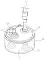
도 1은 종래 의료용 흡인기의 사시도이고, 도 2는 종래 의료용 흡인기의 정면도이다.Fig. 1 is a perspective view of a conventional medical suction device, and Fig. 2 is a front view of a conventional medical suction device.
도 1을 참조하면, 종래 의료용 흡인기는 바닥판(10)과, 상기 바닥판(10)에 일정거리 이격되게 설치되고 배액관(21)이 연결되며 마개(23)가 구비된 배출홀(22)이 형성되는 가압판(20)과, 상기 바닥판(10)과 가압판(20) 사이에 설치되는 코일스프링(30)과, 상기 바닥판(10)과 가압판(20)의 테두리를 연결하여 바닥판(10)과 가압판(20) 사이에 체액을 수용할 수 있는 공간을 형성시키는 밀폐막(40)으로 구성되는 것이 일반적이다1, a conventional medical suction unit includes a
그러나, 상기와 같은 종래 의료용 흡인기는 혈액이나 삼출물과 같은 인체의 체액을 추출하기 위해서 가압판을 상측에서 하측으로 누른 상태에서 배출홀을 밀폐하기 위하여 마개를 막는 추가 동작이 요구되는데, 대부분 여성들로 이루어지는 간호사들이 사용하기에는 힘이 많이 소용되는 문제점이 있다.However, in the conventional medical aspirator, an additional operation of closing the cap to seal the discharge hole while pressing the pressure plate from the upper side to the lower side in order to extract body fluids such as blood or exudates is required. There is a problem that a lot of power is consumed for use.
그리고, 가압판을 누른 후 간호사들이 코일스프링(30)의 탄성을 이기지 못하여 가압판이 일정 높이로 상승한 상태에서 배출홀(22)을 마개(23)로 밀폐하면, 밀폐막(40) 내부에 외부 공기가 유입된 상태에서 인체의 체액이 밀폐막(40) 내부의 공간에 저장되는데, 이렇게 되면 인체의 체액이 외부 공기에 의하여 오염될 수 있는 문제점이 있다.When the nurse can not overcome the elasticity of the
도 3은 종래 의료용 흡인기의 흡인 시간에 따른 압력 변화를 나타내는 그래프이다.3 is a graph showing a change in pressure of the conventional medical suction device according to suction time.
도시된 바와 같이, 종래 의료용 흡인기는 압축된 스프링으로 인해 장착 초기에는 흡인 압력이 강하게 발생하지만 시간이 지나 스프링이 복원됨에 따라 점점 흡인 압력이 약해진다.As shown in the drawing, the suction force of the conventional medical suction device is strongly generated at the initial stage due to the compressed spring, but the suction pressure becomes weaker as the spring is restored over time.
이에 따라, 흡인 시작 시에는 흡인 압력이 너무 강하여 수술부위 조직이 흡인 튜브에 의해 상처나 협착이 발생할 위험이 있으며, 흡인 종반부에는 흡인 압력이 너무 약하여 혈액이나 삼출액을 제대로 배출하지 못하는 문제점이 있다.
Therefore, at the start of suction, the suction pressure is too strong, and there is a risk of injury or stenosis caused by the suction tube in the surgical site tissue, and the suction pressure is too weak at the suction end, so that blood or exudate can not be discharged properly.
상기와 같은 문제점을 해결하기 위해, 본 발명은 수술 부위에 설치한 후 일정한 흡인 압력을 유지함으로써 과한 압력에 의한 수술부 장기 유착, 조직 손상 등의 부작용 사고를 감소시키고, 수술부위 체액을 효과적으로 배출하여 환자의 회복기간 단축에 기여할 수 있는 의료용 흡인기를 제공함에 목적이 있다.In order to solve the above-mentioned problems, the present invention provides a method for preventing side-effects such as long-term adherence of surgical parts and tissue damage due to excessive pressure by maintaining a constant suction pressure after being installed at a surgical site, And to provide a medical aspirator capable of contributing to shortening the recovery period of the patient.
또한, 본 발명은 같은 원리로 음압상처 치료기(Negative Pressure Wound Therapy Device)에도 적용이 가능한 기기를 제공하는데 다른 목적이 있다.
Another object of the present invention is to provide a device that can be applied to a negative pressure wound therapy device on the same principle.
상기와 같은 목적을 달성하기 위한 본 발명의 일 실시예에 따른 흡인 압력이 일정한 의료용 흡인기는 내부에 공간부가 형성된 중공의 실린더 하우징, 상기 실린더 하우징 내에 길이 방향으로 슬라이딩 가능하도록 구비되는 피스톤 및 일단이 상기 피스톤에 연결되고 타단이 상기 실린더 하우징에 고정되며, 상기 피스톤이 일정한 힘으로 길이 방향으로 이동할 수 있도록 하는 탄성부재를 포함하는 것을 특징으로 한다.According to an aspect of the present invention, there is provided a medical suction device having a constant suction pressure, comprising: a hollow cylinder housing having an inner space formed therein; a piston slidable in the longitudinal direction in the cylinder housing; And an elastic member which is connected to the piston and whose other end is fixed to the cylinder housing, and which allows the piston to move in the longitudinal direction with a constant force.
또한, 본 발명의 일 실시예에 따른 상기 탄성부재는 정하중 스프링(constant force spring)인 것을 특징으로 한다.Further, the elastic member according to an embodiment of the present invention is characterized by being a constant force spring.
또한, 본 발명의 일 실시예에 따른 상기 정하중 스프링은 권취단과 고정단을 포함하는 것을 특징으로 한다.Also, the static load spring according to an embodiment of the present invention includes a winding end and a fixed end.
또한, 본 발명의 일 실시예에 따른 상기 실린더 하우징의 일단에는 상기 권취단을 고정시키기 위한 홀더가 장착되는 것을 특징으로 한다.According to an embodiment of the present invention, a holder for fixing the winding end is mounted on one end of the cylinder housing.
또한, 본 발명의 일 실시예에 따른 상기 피스톤에는, 외주면을 따라 장착되는 탄성 재질의 피스톤 링이 장착되는 것을 특징으로 한다.According to an embodiment of the present invention, the piston is mounted with an elastic piston ring mounted along an outer circumferential surface thereof.
또한, 본 발명의 일 실시예에 따른 상기 실린더 하우징의 일단에는 외부에서 상기 피스톤을 가압하여 슬라이딩시키기 위한 개구부가 형성되는 것을 특징으로 한다.According to an embodiment of the present invention, one end of the cylinder housing is formed with an opening for pressing and sliding the piston from the outside.
또한, 본 발명의 일 실시예에 따른 상기 실린더 하우징의 외측면은 중공부를 포함하며, 상기 중공부에는 끝단이 상기 실린더 하우징의 공간부를 향해 돌출 형성되고 돌출 형성된 끝단이 상기 중공부의 외측 방향으로 회전하기 위한 회전력을 가지는 스토퍼가 장착되는 것을 특징으로 한다.According to an embodiment of the present invention, the outer surface of the cylinder housing includes a hollow portion, and an end of the hollow portion is protruded toward a space of the cylinder housing, and a protruding end of the hollow portion is rotated toward the outer side of the hollow portion. And a stopper having a rotational force for the stopper is mounted.
또한, 본 발명의 일 실시예에 따른 상기 실린더 하우징은 외측면에 상기 중공부와 연결되며 길이 방향으로 연장되는 가이드 레일을 포함하며, 상기 가이드 레일에는, 길이 방향으로 슬라이딩함으로써 상기 스토퍼의 회전 여부를 결정하기 위한 스위치가 장착되는 것을 특징으로 한다.According to an embodiment of the present invention, the cylinder housing includes a guide rail connected to the hollow portion on an outer surface thereof and extending in the longitudinal direction, and the guide rail is slidable in the longitudinal direction, And a switch for determining whether or not the switch is turned on.
또한, 본 발명의 일 실시예에 따른 상기 탄성부재는 고정홀을 포함하며, 상기 고정홀에는 상기 실린더 하우징의 외부로부터 삽입 관통되어 상기 피스톤을 걸림 고정시키기 위한 안전핀이 장착되는 것을 특징으로 한다.
In addition, the elastic member according to an embodiment of the present invention includes a fixing hole, and the safety hole is inserted into the fixing hole so as to be inserted from the outside of the cylinder housing and to securely fix the piston.
본 발명은 의료용 흡인기의 음압을 안정적으로 발생시켜 과한 압력에 의한 수술부위 장기 유착, 조직 손상 등 부작용과 사고를 감소시키고, 안정된 음압 발생으로 수술부위 배액을 효과적으로 배출함으로써 환자의 회복기간을 단축시키고 통증을 감소시키는 효과가 있다.The present invention stably generates a sound pressure of a medical aspirator to reduce adverse effects such as long-term adhesion of a surgical site and tissue damage due to excessive pressure, accidental discharge of a surgical site by generating a stable sound pressure, .
또한, 본 발명은 의료용 흡인기의 구조가 간단하여 제조가 용이함에 따라 우수한 생산성을 나타내며, 경제적인 측면에서도 기존의 모든 흡인기 제품에 적용 가능하고 유사 설계가 가능한 제품으로 적용분야가 확대될 가능성이 높은 장점이 있다.
In addition, the present invention can be applied to all the conventional aspirator products in terms of economical efficiency and can be similarly designed because the structure of the medical aspirator is simple and easy to manufacture, .
도 1은 종래 의료용 흡인기의 사시도이다.
도 2는 종래 의료용 흡인기의 정면도이다.
도 3은 일반적인 종래 의료용 흡인기의 흡인 시간에 따른 압력 변화를 나타내는 그래프이다.
도 4는 본 발명의 일 실시예에 따른 의료용 흡인기의 일부 투시 사시도이다.
도 5는 본 발명의 일 실시예에 따른 의료용 흡인기의 활용도이다.
도 6a는 본 발명의 일 실시예에 따른 의료용 흡인기의 작동 전 단면을 나타내기 위한 도면이다.
도 6b는 본 발명의 일 실시예에 따른 의료용 흡인기의 작동 후 단면을 나타내기 위한 도면이다.
도 7은 탄성부재의 종류에 따른 스트로크와 하중의 관계를 나타내는 그래프이다.
도 8a는 본 발명의 일 실시예에 따른 스토퍼가 장착된 의료용 흡인기의 고정 해제 전 단면을 나타내기 위한 도면이다.
도 8b는 본 발명의 일 실시예에 따른 스토퍼가 장착된 의료용 흡인기의 고정 해제 후 단면을 나타내기 위한 도면이다.
도 9a는 본 발명의 일 실시예에 따른 안전핀이 장착된 의료용 흡인기의 고정 해제 전 단면을 나타내기 위한 도면이다.
도 9b는 본 발명의 일 실시예에 따른 안전핀이 장착된 의료용 흡인기의 고정 해제 후 단면을 나타내기 위한 도면이다.
도 10은 본 발명의 다른 실시예에 따른 의료용 흡인기의 일부 투시 사시도이다.
도 11은 본 발명의 다른 실시예에 따른 의료용 흡인기의 활용도이다.
도 12a는 본 발명의 일 실시예에 따른 의료용 흡인기의 작동 전 일부 투시 단면도이다.
도 12b는 본 발명의 일 실시예에 따른 의료용 흡인기의 작동 후 일부 투시 단면도이다.
도 13a는 내측 나사산 연결부에 형성된 선형 나사산의 정면도이다.
도 13b는 내측 나사산 연결부에 형성된 선형 나사산의 전개도이다.
도 14a는 내측 나사산 연결부에 형성된 비선형 나사산의 정면도이다.
도 14b는 내측 나사산 연결부에 형성된 비선형 나사산의 전개도이다.
도 15a 내지 도 15c는 본 발명의 또 다른 실시예에 따른 의료용 흡인기의 작동 과정을 나타내기 위한 도면이다.1 is a perspective view of a conventional medical suction unit.
2 is a front view of a conventional medical suction unit.
FIG. 3 is a graph showing a pressure change according to a suction time of a conventional conventional medical suction device.
4 is a perspective view of a portion of a medical suction device according to an embodiment of the present invention.
5 is an explanatory view of the medical suction device according to an embodiment of the present invention.
6A is a cross-sectional view illustrating an operation front surface of a medical suction unit according to an embodiment of the present invention.
FIG. 6B is a cross-sectional view illustrating an operation of the medical suction unit according to the embodiment of the present invention. FIG.
7 is a graph showing the relationship between the stroke and the load according to the type of the elastic member.
FIG. 8A is a cross-sectional view illustrating an unlocking front surface of a medical suction device equipped with a stopper according to an embodiment of the present invention. FIG.
FIG. 8B is a cross-sectional view of the medical aspirator with the stopper mounted thereon according to an embodiment of the present invention. FIG.
FIG. 9A is a cross-sectional view of a medical aspirator equipped with a safety pin according to an embodiment of the present invention. FIG.
FIG. 9B is a cross-sectional view of the medical aspirator equipped with the safety pin according to an embodiment of the present invention. FIG.
10 is a perspective view of a part of a medical suction unit according to another embodiment of the present invention.
11 is a utilization diagram of a medical suction unit according to another embodiment of the present invention.
12A is a partially perspective cross-sectional view of a medical suction unit according to an embodiment of the present invention.
FIG. 12B is a partial perspective cross-sectional view of the medical aspirator according to an embodiment of the present invention after operation. FIG.
Figure 13a is a front view of a linear thread formed in the inner threaded connection;
13b is an exploded view of a linear thread formed in the inner threaded connection;
14a is a front view of a non-linear thread formed in the inner threaded connection;
14B is an exploded view of the non-linear thread formed in the inner threaded connection;
FIGS. 15A to 15C are diagrams illustrating an operation process of the medical suction unit according to another embodiment of the present invention.
이하에서는 본 발명의 실시 예들을 첨부 도면을 참조하여 상세히 설명한다. 이하에 소개되는 실시 예들은 본 발명이 속하는 기술분야에서 통상의 지식을 가진 자에게 본 발명의 사상이 충분히 전달될 수 있도록 하기 위해 예로서 제공되는 것이다. 본 발명은 이하 설명되는 실시 예들에 한정되지 않고 다른 형태로 구체화될 수도 있다.Hereinafter, embodiments of the present invention will be described in detail with reference to the accompanying drawings. The embodiments described below are provided by way of example so that those skilled in the art will be able to fully understand the spirit of the present invention. The present invention is not limited to the embodiments described below, but may be embodied in other forms.
본 발명을 명확하게 설명하기 위하여 설명과 관계없는 부분은 도면에서 생략하였으며 도면들에 있어서, 구성요소의 폭, 길이, 두께 등은 편의를 위하여 과장되어 표현될 수 있다. 명세서 전체에 걸쳐서 동일한 참조번호들은 동일한 구성요소들을 나타낸다.In order to clearly explain the present invention, parts not related to the description are omitted from the drawings, and the width, length, thickness, etc. of the components may be exaggerated for convenience. Like reference numerals designate like elements throughout the specification.
도 4는 본 발명의 일 실시예에 따른 의료용 흡인기의 일부 투시 사시도이며, 도 5는 본 발명의 일 실시예에 따른 의료용 흡인기의 활용도이다. 본 발명은 이에 한정되지 않고 흡인기를 이용하는 다른 기기에도 당업자가 적절하게 변형 및 수정할 수 있음은 물론이다.FIG. 4 is a partially perspective perspective view of a medical suction unit according to an embodiment of the present invention, and FIG. 5 is an explanatory view of a medical suction unit according to an embodiment of the present invention. It is needless to say that the present invention is not limited to this and other devices using a suction device can be suitably modified and modified by those skilled in the art.
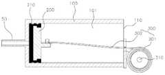
도 6a는 본 발명의 일 실시예에 따른 의료용 흡인기의 작동 전 단면을 나타내기 위한 도면이고, 도 6b는 본 발명의 일 실시예에 따른 의료용 흡인기의 작동 후 단면을 나타내기 위한 도면이다.FIG. 6A is a cross-sectional view illustrating an operation front surface of a medical suction unit according to an embodiment of the present invention, and FIG. 6B is a sectional view after operation of a medical suction unit according to an embodiment of the present invention.
위 도면들을 참조하면, 본 발명의 일 실시예에 따른 의료용 흡인기는 일정한 흡인 압력을 유지하도록 하는 흡인 장치에 관한 것으로, 이를 구현하기 위해 중공의 실린더 하우징(100), 피스톤(200) 및 탄성부재 등을 포함하는 것을 특징으로 한다.Referring to the drawings, a medical suction device according to an embodiment of the present invention is a suction device that maintains a constant suction pressure. To achieve this, a
실린더 하우징(100)은 속이 비어 있는 중공체로서 내부에 단면이 원형인 원통 형상의 공간부(101)가 형성되고, 실린더 하우징(100)에는 공간부(101)의 길이 방향을 따라 슬라이딩 가능하도록 피스톤(200)과 탄성부재가 나란히 구비된다.The
이하에서는, 도 6a 및 6b의 좌우 방향인 실린더 하우징(100)의 원형 단면에 수직인 방향을 길이 방향으로 기재하며 설명한다.Hereinafter, the direction perpendicular to the circular cross section of the
피스톤(200)은 길이 방향에 수직인 단면이 원형이고 소정의 두께를 가지며, 실린더 하우징(100) 내에서 길이 방향으로 슬라이딩 가능하도록 구비되는 것을 특징으로 한다.The
탄성부재는 피스톤(200)에 고정 연결되어 피스톤(200)의 슬라이딩을 가능하도록 하는 일종의 피스톤 로드에 해당되는데, 일단이 피스톤(200)에 연결되고 타단이 실린더 하우징(100)에 고정될 수 있다.The elastic member corresponds to a kind of piston rod fixedly connected to the
도 7은 탄성부재의 종류에 따른 스트로크와 하중의 관계를 나타내는 그래프이다.7 is a graph showing the relationship between the stroke and the load according to the type of the elastic member.
도 7을 참조하면, 일반적인 와이어 스프링은 스트로크가 증가함에 따라 하중도 함께 증가하지만, 본 발명의 탄성부재는 일정 시점을 지나면 스트로크와 관계없이 하중이 일정한 것을 특징으로 한다.Referring to FIG. 7, the load of a general wire spring increases with an increase in stroke, but the load of the elastic member of the present invention is constant regardless of a stroke after a certain point of time.
본 발명에 따른 탄성부재는 피스톤(200)에 연결되어 피스톤(200)이 일정한 힘으로 길이 방향으로 슬라이딩될 수 있도록 하는 것을 특징으로 한다.The elastic member according to the present invention is connected to the
이를 통해, 본 발명에 따른 의료용 흡인기는 흡인 시작부터 종료까지 일정한 흡입 압력을 생성할 수 있다.Thus, the medical suction device according to the present invention can generate a constant suction pressure from the start to the end of suction.
본 발명에 따른 탄성부재는 일정한 곡율로 밴딩된 판 형상의 스프링으로 직선으로 잡아 늘릴 때 생기는 하중이 스트로크에 관계없이 일정한 정하중 스프링(300, constant force spring)인 것이 바람직하다.It is preferable that the elastic member according to the present invention is a constant force spring having a constant load regardless of the stroke when the elastic member is stretched linearly with a plate-shaped spring bent at a constant curvature.
일반적으로 정하중 스프링(300)은 한 방향으로만 하중을 가지기 때문에 본 실시예에서는 일단이 피스톤(200)에 연결되고 타단이 실린더 하우징(100)에 고정됨으로써 피스톤(200)을 스트로크에 관계없이 일정한 하중으로 슬라이딩하고, 이에 따라 일정한 흡인 압력을 유지할 수 있다.Since the
이하에서는 정하중 스프링(300)을 적용한 의료용 흡인기를 기준으로 설명하나, 피스톤(200)이 일정한 힘으로 길이 방향으로 이동할 수 있도록 하는 모든 탄성부재를 포함할 수 있다.Hereinafter, the medical suction device using the
정하중 스프링(300)은 권취단(301)과 고정단(302)을 포함할 수 있으며, 고정단(302)은 피스톤(200)과 걸림 고정을 통해 연결될 수 있고, 권취단(301)은 실린더 하우징(100)의 일단에 장착된 홀더(310)에 의해 고정될 수 있다.The
권취단(301)은 중앙이 비어 있는 코일 형상을 가지며, 홀더(310)는 권취단(301)의 중앙 부분을 관통함으로써 정하중 스프링(300)을 고정시킬 수 있다.The winding
권취단(301)이 회전하게 되면 고정단(302)의 길이가 감소하고 정하중 스프링(300)이 압축되며, 고정단(302)과 연결된 피스톤(200)은 실린더 하우징(100)에 고정된 권취단(301)을 향해 길이 방향으로 슬라이딩될 수 있다.When the winding
피스톤(200)에는 외주면을 따라 장착되는 탄성 재질의 피스톤 링(210)이 장착될 수 있으며, 피스톤(200)과 실린더 하우징(100) 사이를 밀봉함으로써 공기나 삼출물(80)의 유출을 방지하고 흡인 압력을 유지할 수 있다.An elastic
본 발명의 일 실시예에 따른 의료용 흡인기의 작동 과정을 설명하면 다음과 같다.The operation of the medical aspirator according to an embodiment of the present invention will be described as follows.
도 6a를 참조하면, 정하중 스프링(300)을 최대로 팽창시켜 피스톤(200)이 실린더 하우징(100)의 타단에 접촉되도록 한다.Referring to FIG. 6A, the static-
실린더 하우징(100)의 일단에는 외부에서 피스톤(200)을 가압하여 슬라이딩시키기 위한 개구부(110)가 형성될 수 있다.One end of the
예를 들면, 개구부(110)를 통해 사용자가 손을 집어넣어 피스톤(200)의 일면을 가압함으로써 피스톤(200)의 타면이 실린더 하우징(100)의 내측면에 접촉되도록 할 수 있다.For example, the user can push the one side of the
이 경우, 흡입구(50)는 피스톤(200)이나 피스톤 링(210)에 의해 폐쇄되며 삼출물(80)이 실린더 하우징(100)의 내부로 유입되는 것을 막을 수 있다.In this case, the
피스톤(200)은 사용자가 신체를 이용하여 직접적으로 고정시킬 수 있으나, 후술하는 바와 같이 별도의 고정 수단에 의해 고정되는 것도 가능하다.The
도 6b를 참조하면, 피스톤(200)의 고정이 해제되면 정하중 스프링(300)은 압축되며 피스톤(200)을 길이 방향으로 슬라이딩시킨다.Referring to FIG. 6B, when the
피스톤(200)이 슬라이딩됨에 따라 피스톤(200)이나 피스톤 링(210)에 의해 폐쇄되어 있던 흡입구(50)는 개방되며 흡입구(50)와 연결된 배액튜브(60)나 트로카(70) 등으로부터 삼출물(80)이 실린더 하우징(100)의 내부로 유입되는데, 본 발명의 탄성부재 특성에 따라 이 과정에서의 흡인 압력은 일정하게 유지된다.The
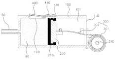
도 8a는 본 발명의 일 실시예에 따른 스토퍼가 장착된 의료용 흡인기의 고정 해제 전 단면을 나타내기 위한 도면이고, 도 8b는 본 발명의 일 실시예에 따른 스토퍼가 장착된 의료용 흡인기의 고정 해제 후 단면을 나타내기 위한 도면이다.FIG. 8A is a cross-sectional view of a medical aspirator equipped with a stopper according to an embodiment of the present invention, and FIG. 8B is a cross-sectional view of a medical aspirator equipped with a stopper according to an embodiment of the present invention. Fig.
도 8a 및 도 8b를 참조하면, 실린더 하우징(100)은 외측면에 스토퍼(400)가 장착되기 위한 중공부(120)를 포함할 수 있다.8A and 8B, the
스토퍼(400)는 정하중 스프링(300)이 최대로 팽창 시 정하중 스프링(300)의 압축력에 대항하여 피스톤(200)을 고정시키기 위한 장치이며, 끝단이 피스톤(200)을 걸림 고정시키도록 실린더 하우징(100)의 공간부(101)를 향해 돌출 형성될 수 있다.The
즉, 스토퍼(400)의 돌출된 부분이 피스톤(200)의 일측면을 지탱함으로써 정하중 스프링(300)이 압축되는 것을 방지할 수 있다.That is, the protruding portion of the
돌출 형성된 끝단은 기본적으로 중공부(120)의 외측 방향으로 회전하기 위한 회전력을 가질 수 있으며, 이를 위해 스프링이나 와이어 등과 같은 부재(미도시)가 추가로 장착될 수 있다.The protruding end may have a rotational force for rotating the
따라서, 스토퍼(400)는 중공부(120)의 외측 방향으로 소정의 각도로 회전할 수 있으며, 이에 따라 스토퍼(400)의 돌출 형성된 끝단이 상승하여 피스톤(200)의 걸림 고정을 해제시킬 수 있다.Accordingly, the
실린더 하우징(100)은 외측면에 중공부(120)와 연결되며 길이 방향으로 연장되는 가이드 레일(130)을 포함할 수 있다. 가이드 레일(130)에는 길이 방향으로 슬라이딩함으로써 스토퍼(400)의 회전 여부를 결정하기 위한 스위치(410)가 장착될 수 있다.The
본 발명의 일 실시예에 따른 피스톤(200) 고정 수단이 장착된 의료용 흡인기의 작동 과정을 설명하면 다음과 같다.The operation of the medical aspirator equipped with the
도 8a를 참조하면, 정하중 스프링(300)을 최대로 팽창시켜 피스톤(200)이 실린더 하우징(100)의 내측면에 접촉되도록 한다.Referring to FIG. 8A, the static-
스토퍼(400)의 돌출된 부분의 일측면은 실린더 하우징(100)의 길이 방향에 수직이 되도록 형성되고 타측면은 반대 방향으로 경사지게 형성된다.One side of the protruded portion of the
스토퍼(400)의 끝단이 위와 같은 비대칭 형상을 가짐에 따라, 피스톤(200)은 스토퍼(400)를 지나 흡입구(50) 방향으로 슬라이딩되는 것은 용이하나, 스토퍼(400)를 지난 후에는 반대 방향으로의 이동이 스토퍼(400)에 의해 억제되어 고정될 수 있다.Since the end of the
가이드 레일(130)에 장착된 스위치(410)는 스토퍼(400)의 외측면에 위치하여 스토퍼(400)가 중공부(120)의 외측 방향으로 회전되는 것을 방지할 수 있다.The
도 8b를 참조하면, 흡인기의 작동을 위해 스위치(410)는 가이드 레일(130)을 따라 길이 방향으로 슬라이딩되며, 스토퍼(400)는 회전력에 의해 돌출된 부분이 소정 각도로 실린더 하우징(100)의 외측 방향으로 회전하여 피스톤(200)의 걸림 고정이 해제된다.8B, the
도면상에서는 스토퍼(400)가 회전함으로써 피스톤(200)의 걸림 고정이 해제되는 것을 도시하고 있으나, 스토퍼(400)가 수직으로 상승함으로써 피스톤(200)의 고정을 해제시킬 수 있으며, 스토퍼(400)의 회전과 수직 운동이 복합적으로 작용하는 것도 가능하다.Although the
이와 같은 스토퍼(400)와 스위치(410)의 구조는 일례에 해당되는 것이며, 이에 제한되는 것은 아니다.The structure of the
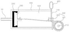
도 9a는 본 발명의 일 실시예에 따른 안전핀이 장착된 의료용 흡인기의 고정 해제 전 단면을 나타내기 위한 도면이고, 도 9b는 본 발명의 일 실시예에 따른 안전핀이 장착된 의료용 흡인기의 고정 해제 후 단면을 나타내기 위한 도면이다.FIG. 9A is a cross-sectional view of a medical suction device equipped with a safety pin according to an embodiment of the present invention, FIG. 9B is a cross-sectional view of a medical suction device with a safety pin attached thereto according to an embodiment of the present invention, Fig.
도 9a 및 도 9b를 참조하면, 탄성부재는 고정홀(미도시)을 포함할 수 있으며, 고정홀에는 실린더 하우징(100)의 외부로부터 삽입 관통되어 상기 피스톤(200)을 걸림 고정시키기 위한 안전핀(420)이 장착될 수 있다.9A and 9B, the elastic member may include a fixing hole (not shown). The fixing hole may include a safety pin (not shown) for inserting the
이때, 실린더 하우징(100)의 외측면에는 안전핀(420)이 삽입 관통되도록 핀 홀(140)이 추가로 형성될 수 있다.At this time, a
본 발명의 일 실시예에 따른 안전핀(420)이 장착된 의료용 흡인기의 작동 과정을 설명하면 다음과 같다.The operation of the medical suction unit equipped with the
도 9a를 참조하면, 정하중 스프링(300)을 최대로 팽창시켜 피스톤(200)이 실린더 하우징(100)의 타단에 접촉되도록 한다. 그 다음, 안전핀(420)을 핀 홀(140)과 고정홀에 삽입 관통시켜 피스톤(200)을 걸림 고정시킨다.Referring to FIG. 9A, the static-
도 9b를 참조하면, 흡인기의 작동을 위해 안전핀(420)을 실린더 하우징(100)의 외부로 제거하여 피스톤(200)의 걸림 고정을 해제시킬 수 있으며, 다른 흡인 과정은 위와 동일하다.Referring to FIG. 9B, the
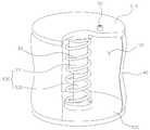
도 10은 본 발명의 다른 실시예에 따른 의료용 흡인기의 일부 투시 사시도이며, 도 11은 본 발명의 다른 실시예에 따른 의료용 흡인기의 활용도이다. 본 발명은 이에 한정되지 않고 흡인기를 이용하는 다른 기기에도 당업자가 적절하게 변형 및 수정할 수 있음은 물론이다.FIG. 10 is a perspective view of a part of a medical suction unit according to another embodiment of the present invention, and FIG. 11 is an explanatory view of a medical suction unit according to another embodiment of the present invention. It is needless to say that the present invention is not limited to this and other devices using a suction device can be suitably modified and modified by those skilled in the art.
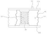
도 12a는 본 발명의 일 실시예에 따른 의료용 흡인기의 작동 전 일부 투시 단면도이고, 도 12b는 본 발명의 일 실시예에 따른 의료용 흡인기의 작동 후 일부 투시 단면도이다.FIG. 12A is a partial perspective cross-sectional view of the medical suction unit according to an embodiment of the present invention, and FIG. 12B is a partial perspective sectional view after operation of the medical suction unit according to an embodiment of the present invention.
위 도면들을 참조하면, 본 발명의 다른 실시예에 따른 의료용 흡인기는 일정한 흡인 압력을 유지하도록 하는 흡인 장치에 관한 것으로, 이를 구현하기 위해 상부 하우징(510), 하부 하우징(520), 밀폐막(40), 나사산 연결부(530), 코일스프링(30) 등을 포함하는 것을 특징으로 한다.Referring to the drawings, a medical suction device according to another embodiment of the present invention relates to a suction device that maintains a predetermined suction pressure. In order to achieve this, an
하부 하우징(520)은 의료용 흡인기의 하부 바디를 구성하며, 상부 하우징(510)은 의료용 흡인기의 상부 하우징(510)을 구성하고 하부 하우징(520)을 향해 가압될 수 있다.The
상부 하우징(510)과 하부 하우징(520)은 동일한 형상을 가지는 것이 바람직하며, 상부 하우징(510)과 하부 하우징(520)의 외측면을 따라 밀폐막(40)이 결합되어 내부에 공간부(101)를 형성할 수 있다.It is preferable that the
일례로 상부 하우징(510) 및 하부 하우징(520)은 원판 형상을 가지며, 나사선 연결부(530)는 상부 하우징(510)과 하부 하우징(520)의 중심을 연결할 수 있다.For example, the
이하에서는, 도 12a 및 12b의 상하 방향이며 상부 하우징(510) 및 하부 하우징(520)에 수직인 방향을 높이 방향으로 기재하며 설명한다.Hereinafter, the vertical direction of FIGS. 12A and 12B and the direction perpendicular to the
나사산 연결부(530)는 상부 하우징(510)과 하부 하우징(520)을 연결하며 나사산이 형성되는 것을 특징으로 하며, 나사산 연결부(530)의 외주면에는 코일스프링(30)이 장착될 수 있다.The
코일스프링(30)은 높이 방향으로 압축되거나 팽창될 수 있으며, 이에 따라 나사산 연결부(530)도 코일스프링(30)과 함께 높이 방향으로 압축되거나 팽창될 수 있다.The
나사산 연결부(530)는, 상부 하우징(510)에 결합되는 외측 나사산 연결부(531)와, 하부 하우징(520)에 결합되며 외측 나사산 연결부(531)에 삽입되는 내측 나사산 연결부(532)를 포함할 수 있다.The threaded
나사산 연결부(530)는 상부 하우징(510) 및 하부 하우징(520_과 일체로 형성될 수 있으며, 별개의 구성을 형성하여 체결될 수도 있다.The threaded
본 발명의 다른 실시예에 따른 의료용 흡인기는 기존의 선형적인 스프링의 특성을 벗어나기 위해 나사산으로 연결부를 구성하는 것을 특징으로 한다.The medical aspirator according to another embodiment of the present invention is characterized in that a connecting portion is formed of a thread to deviate from the characteristics of a conventional linear spring.
이를 통해, 초기 강한 스프링의 힘을 나사산의 마찰력으로 상쇄시켜 흡인 시작 시에 흡인 압력이 지나치게 강해지는 것을 방지함으로써 흡인 압력을 일정 수즌으로 유지시킬 수 있다.This allows the force of the initial strong spring to be canceled by the frictional force of the thread to prevent the suction pressure from becoming too strong at the start of the suction, thereby maintaining the suction pressure at a constant level.
게다가, 상부 하우징(510)을 가압할 때 사용되는 수직 방향의 힘을 회전 방향으로 전환시킴으로써 의료 분야에서 대부분 여성들로 이루어진 간호사들도 용이하게 사용하도록 할 수 있다.In addition, by switching the vertical force used to press the
나사산은 볼트, 너트 구조 외에도 볼 스크류 및 이와 유사한 나사산 등 당해 기술분야에 사용되는 모든 구조를 사용할 수 있다.The threads may be of any structure used in the art, such as bolts and nuts, as well as ball screws and similar threads.
밀폐막(40)은 주름진 형상을 가질 수 있으며, 코일스프링(30)이 팽창함에 따라 함께 팽창하여 내부에 형성되는 공간부(101)의 부피를 증가시킬 수 있다.The sealing
본 발명의 다른 실시예에 따른 의료용 흡인기의 작동 과정을 설명하면 다음과 같다.The operation of the medical suction unit according to another embodiment of the present invention will now be described.
도 12a를 참조하면, 상부 하우징(510)을 하부 하우징(520) 방향으로 가압하며 이 과정에서 내측 나사산 연결부(532)는 외측 나사산 연결부(531)의 내부에 삽입되고 코일스프링(30)은 압축된다.12A, the
코일스프링(30)이 압축된 후에는 상부 하우징(510)과 하부 하우징(520)을 고정하기 위한 클립과 같은 별도의 고정 수단을 구비할 수 있다.After the
즉, 흡인기 장착 전에는 코일스프링(30)의 팽창하려는 힘을 억제하기 위해 상부 하우징(510)과 하부 하우징(520)을 강하게 고정시킬 필요가 있다.That is, it is necessary to strongly fix the
도 12b를 참조하면, 흡인기의 작동을 위해 고정 수단을 제거함에 따라 코일스프링(30)은 서서히 팽창하게 되고 주름진 형상의 밀폐막(40)도 팽창하여 내부 공간부(101)의 부피가 증가하며 이에 따라 흡입구(50)를 통해 삼출물(80)이 유입된다.12B, as the fixing means is removed for the operation of the suction device, the
이때, 나사산 연결부(530)의 나사산에 의해 초기 강한 코일스프링(30)의 힘을 나사산의 마찰력으로 상쇄시킴으로써 흡인 압력을 일정하게 할 수 있다.At this time, the force of the initial
나사산은 외측 나사산 연결부(531)의 내측과 내측 나사산 연결부(532)의 외측에 형성될 수 있으며 서로 상보적인 형상을 가지는 것이 바람직하다.The threads may be formed on the inner side of the outer threaded
도 13a는 내측 나사산 연결부에 형성된 선형 나사산의 정면도이고, 도 13b는 내측 나사산 연결부에 형성된 선형 나사산의 전개도이고, 도 14a는 내측 나사산 연결부에 형성된 비선형 나사산의 정면도이고, 도 14b는 내측 나사산 연결부에 형성된 비선형 나사산의 전개도이다.Figure 13a is a front view of a linear thread formed in the inner threaded connection, Figure 13b is an exploded view of the linear thread formed in the inner threaded connection, Figure 14a is a front view of the non-linear thread formed in the inner threaded connection, It is a developed view of nonlinear thread.
위 도면들을 참조하면, 나사산의 형상을 나타내기 위해 내측 나사산 연결부(532)를 제외한 다른 구성들을 생략하였다.Referring to the above drawings, other configurations except for the inner
도 13a 및 도 13b는 선형 나사산(533)을 나타낸 것인데, 나사산의 마찰력 및 기울기만으로 초기 압력의 변화를 조절할 수 없을 경우에는 도 14a 및 도 14b에 도시된 바와 같이 비선형 나사산(534)을 구현함에 따라 압력 변동률을 조절하여 궁극적으로 흡인 압력을 일정 수준으로 유지할 수 있다.FIGS. 13A and 13B show the
이때, 나사산은, 나사산에 접하는 접선의 기울기가 상부 하우징(510) 방향으로 갈수록 증가하도록 형성되는 것이 바람직하다.At this time, it is preferable that the thread is formed such that the inclination of the tangent line in contact with the thread increases toward the
이에 따라, 장착 초기에는 초기 강한 스프링의 힘을 기울기가 낮은 나사산의 강한 마찰력으로 억제할 수 있으며, 시간이 지남에 따라 약해지는 스프링의 힘은 기울기가 큰 나사산의 마찰력으로 보완할 수 있는데, 이는 코일스프링(30)의 팽창력과 나사산의 마찰력의 합을 고려한 것이며, 작동 시간에 관계 없이 흡인 압력을 더욱 일정하게 유지할 수 있다.Accordingly, the force of the initial strong spring can be suppressed by the strong frictional force of the low inclined thread, and the force of the weakened spring over time can be compensated by the frictional force of the inclined thread, The sum of the expansion force of the
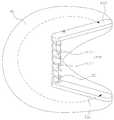
도 15a 내지 도 15c는 본 발명의 또 다른 실시예에 따른 의료용 흡인기의 작동 과정을 나타내기 위한 도면이다.FIGS. 15A to 15C are diagrams illustrating an operation process of the medical suction unit according to another embodiment of the present invention.
도 15a 내지 도 15c를 참조하면, 상부 하우징(510) 및 하부 하우징(520)은 너비 대비 길이가 긴 막대 형상을 가지며, 나사선 연결부(530)는 상부 하우징(510)과 하부 하우징(520)의 일단을 연결하는 것을 특징으로 한다.15A to 15C, the
상부 하우징(510)은 코일스프링(30)이 팽창함에 따라 하부 하우징(520)을 기준으로 회전하며, 밀폐막(40)은 부채꼴 형상으로 펼쳐질 수 있다.The
상부 하우징(510)과 하부 하우징(520)이 원통 형상인 경우에는 최대 180도 정도의 회전만이 가능하여 용량 측면에서나 압력 변화에 다소 취약한 문제가 있다.When the
이와 달리, 밀폐막(40)이 부채꼴 형상으로 펼쳐지는 경우에는 대략 270도 이상까지도 회전이 가능하여 용량 측면에서 압력 변화 측면에서 매우 우수한 장점이 있다.On the other hand, when the sealing
본 발명의 또 다른 실시예에 따른 의료용 흡인기의 작동 과정을 설명하면 다음과 같다.The operation of the medical suction unit according to another embodiment of the present invention will be described as follows.
도 15a를 참조하면, 상부 하우징(510)을 하부 하우징(520) 방향으로 가압하며 이 과정에서 내측 나사산 연결부(532)는 외측 나사산 연결부(531)의 내부에 삽입되고 코일스프링(30)은 압축된다.15A, the
코일스프링(30)이 압축된 후에는 상부 하우징(510)과 하부 하우징(520)을 고정하기 위한 클립과 같은 별도의 고정 수단을 구비할 수 있다.After the
도 15b를 참조하면, 흡인기를 작동시키기 위해 고정 수단을 제거함에 따라 코일스프링(30)은 서서히 팽창하게 되고, 상부 하우징(510)은 코일스프링(30)이 팽창함에 따라 하부 하우징(520)을 기준으로 대략 90도 정도 회전 및 상승하고, 밀폐막(40)은 부채꼴 형상으로 펼쳐진다.15B, the
도 15c를 참조하면, 코일스프링(30)은 더욱 팽창하게 되고, 상부 하우징(510)은 코일스프링(30)이 더욱 팽창함에 따라 하부 하우징(520)을 기준으로 대략 260도 정도까지 회전 및 상승하게 된다.15C, the
이 과정에서 흡입구(50)를 통해 삼출물(80)이 유입될 수 있으며, 의료용 흡인기가 부채꼴 형상을 가짐에 따라 회전 각도가 상승하여 더욱 우수한 용량 효율성을 나타낼 수 있다.In this process, the
상기와 같이 도면과 명세서에서 최적의 실시예가 개시되었다. 여기서 특정한 용어들이 사용되었으나, 이는 단지 본 발명을 설명하기 위한 목적에서 사용된 것이지 의미 한정이나 특허청구범위에 기재된 본 발명의 범위를 제한하기 위하여 사용된 것은 아니다. 그러므로, 본 기술 분야의 통상의 지식을 가진 자라면 이로부터 다양한 변형 및 균등한 타 실시예가 가능하다는 점을 이해할 것이다. 따라서, 본 발명의 진정한 기술적 보호범위는 첨부된 특허청구범위의 기술적 사상에 의해 정해져야 할 것이다.
As described above, an optimal embodiment has been disclosed in the drawings and specification. Although specific terms have been employed herein, they are used for purposes of illustration only and are not intended to limit the scope of the invention as defined in the claims or the claims. Therefore, those skilled in the art will appreciate that various modifications and equivalent embodiments are possible without departing from the scope of the present invention. Accordingly, the true scope of the present invention should be determined by the technical idea of the appended claims.
10: 바닥판
20: 가압판
21: 배액관
22: 배출홀
23: 마개
30: 코일스프링
40: 밀폐막
50: 흡입구
60: 배액튜브
70: 트로카
80: 삼출물
100: 실린더 하우징
101: 공간부
110: 개구부
120: 중공부
130: 가이드 레일
140: 핀 홀
200: 피스톤
210: 피스톤 링
300: 정하중 스프링
301: 권취단
302: 고정단
310: 홀더
402: 스토퍼
410: 스위치
420: 안전핀
510: 상부 하우징
520: 하부 하우징
530: 나사산 연결부
531: 외측 나사산 연결부
532: 내측 나사산 연결부
533: 선형 나사산
534: 비선형 나사산10: bottom plate
20: Platen
21: Drain tube
22: discharge hole
23: Plug
30: coil spring
40: sealing film
50: inlet
60: Drain tube
70: Trocar
80: exudate
100: cylinder housing
101:
110: opening
120: hollow
130: Guide rail
140: pin hole
200: piston
210: Piston ring
300: static load spring
301: Winding stage
302: Fixed end
310: holder
402: Stopper
410: switch
420: Safety pin
510: upper housing
520: Lower housing
530:
531: Outer thread connection
532: Inner threaded connection
533: Linear thread
534: Nonlinear threading
Claims (9)
Translated fromKorean상기 실린더 하우징 내에 길이 방향으로 슬라이딩 가능하도록 구비되는 피스톤; 및
일단이 상기 피스톤에 연결되고 타단이 상기 실린더 하우징에 고정되며, 상기 피스톤이 일정한 힘으로 길이 방향으로 이동할 수 있도록 하는 탄성부재를 포함하고,
상기 실린더 하우징의 일단에는 외부에서 상기 피스톤을 가압하여 슬라이딩시키기 위한 개구부가 형성되고,
상기 실린더 하우징의 외측면은 중공부를 포함하며,
상기 중공부에는 끝단이 상기 실린더 하우징의 공간부를 향해 돌출 형성되고 돌출 형성된 끝단이 상기 중공부의 외측 방향으로 회전하기 위한 회전력을 가지는 스토퍼가 장착되고,
상기 실린더 하우징은 외측면에 상기 중공부와 연결되며 길이 방향으로 연장되는 가이드 레일을 포함하며,
상기 가이드 레일에는, 길이 방향으로 슬라이딩함으로써 상기 스토퍼의 회전 여부를 결정하기 위한 스위치가 장착되는 것을 특징으로 하는 흡인 압력이 일정한 의료용 흡인기.
A hollow cylinder housing having a space formed therein;
A piston slidable in the longitudinal direction within the cylinder housing; And
An elastic member having one end connected to the piston and the other end fixed to the cylinder housing and allowing the piston to move in a longitudinal direction with a constant force,
Wherein one end of the cylinder housing is formed with an opening for pressing and sliding the piston from the outside,
Wherein the outer surface of the cylinder housing includes a hollow portion,
Wherein the hollow portion has a stopper protruding from the hollow portion toward the space of the cylinder housing and having a rotational force for rotating the protruding end in the outward direction of the hollow portion,
Wherein the cylinder housing includes a guide rail connected to the hollow portion on an outer side surface and extending in the longitudinal direction,
And a switch for determining whether the stopper is rotated by sliding in the longitudinal direction is mounted on the guide rail.
상기 탄성부재는 정하중 스프링(constant force spring)인 것을 특징으로 하는 흡인 압력이 일정한 의료용 흡인기.
The method according to claim 1,
Wherein the elastic member is a constant force spring.
상기 정하중 스프링은 권취단과 고정단을 포함하는 것을 특징으로 하는 흡인 압력이 일정한 의료용 흡인기.
3. The method of claim 2,
Wherein the static force spring includes a winding end and a fixed end.
상기 실린더 하우징의 일단에는 상기 권취단을 고정시키기 위한 홀더가 장착되는 것을 특징으로 하는 흡인 압력이 일정한 의료용 흡인기.
The method of claim 3,
And a holder for fixing the winding end is mounted on one end of the cylinder housing.
상기 피스톤에는, 외주면을 따라 장착되는 탄성 재질의 피스톤 링이 장착되는 것을 특징으로 하는 흡인 압력이 일정한 의료용 흡인기.
The method according to claim 1,
Characterized in that the piston is equipped with a piston ring of an elastic material mounted along the outer circumferential surface thereof.
상기 탄성부재는 고정홀을 포함하며,
상기 고정홀에는 상기 실린더 하우징의 외부로부터 삽입 관통되어 상기 피스톤을 걸림 고정시키기 위한 안전핀이 장착되는 것을 특징으로 하는 흡인 압력이 일정한 의료용 흡인기.The method according to claim 1,
The elastic member includes a fixing hole,
And a safety pin for inserting the piston from the outside of the cylinder housing and fixing the piston is mounted in the fixing hole.
Priority Applications (4)
| Application Number | Priority Date | Filing Date | Title |
|---|---|---|---|
| KR1020150158308AKR101760742B1 (en) | 2015-11-11 | 2015-11-11 | Medical suction unit with constant suction pressure |
| EP16864615.6AEP3363479A4 (en) | 2015-11-11 | 2016-11-11 | MEDICAL SUCTION DEVICE WITH CONSTANT SUCTION PRESSURE |
| PCT/KR2016/013030WO2017082689A1 (en) | 2015-11-11 | 2016-11-11 | Medical suction device having constant suction pressure |
| US15/775,208US10973964B2 (en) | 2015-11-11 | 2016-11-11 | Medical aspirator having constant suction pressure |
Applications Claiming Priority (1)
| Application Number | Priority Date | Filing Date | Title |
|---|---|---|---|
| KR1020150158308AKR101760742B1 (en) | 2015-11-11 | 2015-11-11 | Medical suction unit with constant suction pressure |
Related Child Applications (1)
| Application Number | Title | Priority Date | Filing Date |
|---|---|---|---|
| KR1020170087834ADivisionKR102239217B1 (en) | 2017-07-11 | 2017-07-11 | Medical suction unit with constant suction pressure |
Publications (2)
| Publication Number | Publication Date |
|---|---|
| KR20170055297A KR20170055297A (en) | 2017-05-19 |
| KR101760742B1true KR101760742B1 (en) | 2017-07-24 |
Family
ID=59049422
Family Applications (1)
| Application Number | Title | Priority Date | Filing Date |
|---|---|---|---|
| KR1020150158308AActiveKR101760742B1 (en) | 2015-11-11 | 2015-11-11 | Medical suction unit with constant suction pressure |
Country Status (1)
| Country | Link |
|---|---|
| KR (1) | KR101760742B1 (en) |
Families Citing this family (1)
| Publication number | Priority date | Publication date | Assignee | Title |
|---|---|---|---|---|
| CN117838957B (en)* | 2024-02-23 | 2024-07-23 | 茂名市德力康医疗科技有限公司 | Auxiliary negative pressure drainage device for disposable negative pressure drainage bottle |
Citations (2)
| Publication number | Priority date | Publication date | Assignee | Title |
|---|---|---|---|---|
| US8858516B2 (en)* | 2010-08-10 | 2014-10-14 | Spiracur Inc. | Controlled negative pressure apparatus and absorbency mechanism |
| US9283307B2 (en) | 2008-02-14 | 2016-03-15 | Kci Licensing, Inc. | Devices and methods for treatment of damaged tissue |
- 2015
- 2015-11-11KRKR1020150158308Apatent/KR101760742B1/enactiveActive
Patent Citations (2)
| Publication number | Priority date | Publication date | Assignee | Title |
|---|---|---|---|---|
| US9283307B2 (en) | 2008-02-14 | 2016-03-15 | Kci Licensing, Inc. | Devices and methods for treatment of damaged tissue |
| US8858516B2 (en)* | 2010-08-10 | 2014-10-14 | Spiracur Inc. | Controlled negative pressure apparatus and absorbency mechanism |
Also Published As
| Publication number | Publication date |
|---|---|
| KR20170055297A (en) | 2017-05-19 |
Similar Documents
| Publication | Publication Date | Title |
|---|---|---|
| US10973964B2 (en) | Medical aspirator having constant suction pressure | |
| JP6989595B2 (en) | Pressure jacket with syringe holding element | |
| US20250099132A1 (en) | Trocar cannula assembly with low profile insertion configuration and method of manufacture | |
| CN103608050B (en) | Connection system for detachably fastening hollow cylindrical parts in recesses | |
| US20130172681A1 (en) | Wound protector with reinforced ring | |
| WO2009053952A3 (en) | A medical device for use in treatment of a valve | |
| CA2660692A1 (en) | Injection device with simplified stopper retention | |
| JP2018537181A (en) | Surgical trocar | |
| CN108136134B (en) | Syringe with retractable needle | |
| WO2022147998A1 (en) | Expansion tube, vascular sheath device, cooperation structure of vascular sheath device and pre-expander, and pre-expander | |
| KR101760742B1 (en) | Medical suction unit with constant suction pressure | |
| KR20170085466A (en) | Medical suction unit with constant suction pressure | |
| KR101752685B1 (en) | Medical suction unit with constant suction pressure | |
| RU2463019C2 (en) | Receiving socket of prostyhesis for extremity stump, equipped with inbuilt fixing device for sealing element | |
| JP2008206879A (en) | Medical excretion tool and medical excretion tool set | |
| US9480827B2 (en) | Drainage cannula with anchor tab | |
| CN114099064B (en) | An in-vivo artificial urinary sphincter device | |
| US20140088568A1 (en) | Drainage cannula with anchor tab | |
| CN209108263U (en) | Infusion port puncture fixer and infusion port fixing assembly | |
| CN205494639U (en) | Medical small flowing back drainage tube | |
| US20250114121A1 (en) | Surgical cannula with a length self-adjusting mechanism and movable negative pressure seal anchor | |
| WO2018149751A1 (en) | Access device | |
| CN222466981U (en) | Automatic locking fascia wire clamping device | |
| CN209864989U (en) | Balloon dilatation device for general surgery department | |
| CN216456223U (en) | Chest closed drainage bottle |
Legal Events
| Date | Code | Title | Description |
|---|---|---|---|
| PA0109 | Patent application | Patent event code:PA01091R01D Comment text:Patent Application Patent event date:20151111 | |
| PA0201 | Request for examination | ||
| PE0902 | Notice of grounds for rejection | Comment text:Notification of reason for refusal Patent event date:20161123 Patent event code:PE09021S01D | |
| PG1501 | Laying open of application | ||
| E701 | Decision to grant or registration of patent right | ||
| PE0701 | Decision of registration | Patent event code:PE07011S01D Comment text:Decision to Grant Registration Patent event date:20170522 | |
| PA0107 | Divisional application | Comment text:Divisional Application of Patent Patent event date:20170711 Patent event code:PA01071R01D | |
| GRNT | Written decision to grant | ||
| PR0701 | Registration of establishment | Comment text:Registration of Establishment Patent event date:20170718 Patent event code:PR07011E01D | |
| PR1002 | Payment of registration fee | Payment date:20170719 End annual number:3 Start annual number:1 | |
| PG1601 | Publication of registration | ||
| PR1001 | Payment of annual fee | Payment date:20200713 Start annual number:4 End annual number:4 | |
| PR1001 | Payment of annual fee | Payment date:20210712 Start annual number:5 End annual number:5 | |
| PR1001 | Payment of annual fee | Payment date:20220802 Start annual number:6 End annual number:6 | |
| PR1001 | Payment of annual fee | Payment date:20230628 Start annual number:7 End annual number:7 | |
| PR1001 | Payment of annual fee | Payment date:20240701 Start annual number:8 End annual number:8 |