KR101759532B1 - A method for estimating an internal impedance of a battery - Google Patents
A method for estimating an internal impedance of a batteryDownload PDFInfo
- Publication number
- KR101759532B1 KR101759532B1KR1020150154851AKR20150154851AKR101759532B1KR 101759532 B1KR101759532 B1KR 101759532B1KR 1020150154851 AKR1020150154851 AKR 1020150154851AKR 20150154851 AKR20150154851 AKR 20150154851AKR 101759532 B1KR101759532 B1KR 101759532B1
- Authority
- KR
- South Korea
- Prior art keywords
- frequency
- battery
- input voltage
- voltage
- internal impedance
- Prior art date
- Legal status (The legal status is an assumption and is not a legal conclusion. Google has not performed a legal analysis and makes no representation as to the accuracy of the status listed.)
- Active
Links
Images


Classifications
- G01R31/3662—
- G—PHYSICS
- G01—MEASURING; TESTING
- G01R—MEASURING ELECTRIC VARIABLES; MEASURING MAGNETIC VARIABLES
- G01R27/00—Arrangements for measuring resistance, reactance, impedance, or electric characteristics derived therefrom
- G01R27/02—Measuring real or complex resistance, reactance, impedance, or other two-pole characteristics derived therefrom, e.g. time constant
- G01R27/08—Measuring resistance by measuring both voltage and current
- G01R31/3624—
- G01R31/3658—
- G01R31/3679—
Landscapes
- Physics & Mathematics (AREA)
- General Physics & Mathematics (AREA)
- Secondary Cells (AREA)
- Measurement Of Resistance Or Impedance (AREA)
Abstract
Translated fromKoreanDescription
Translated fromKorean본 발명은 배터리의 내부 임피던스를 추정하는 방법에 관한 것으로, 보다 상세하게는 상기 내부 임피던스를 추정하여 배터리의 상태를 판단하는 방법 및 장치에 관한 것이다.BACKGROUND OF THE INVENTION 1. Field of the Invention [0001] The present invention relates to a method of estimating internal impedance of a battery, and more particularly, to a method and apparatus for estimating internal impedance to determine a state of a battery.
이동 단말기 및 전기 자동차 등에 있어서, 배터리(battery)의 충전 용량 및 상태를 파악하는 것은 무엇보다도 중요하다.In mobile terminals, electric vehicles and the like, it is important to grasp the charging capacity and state of the battery.
배터리에 의한 전기 에너지를 이용하는 이동 단말기 및 전기 자동차는 배터리의 성능이 이동 단말기 및 전기 자동차의 성능에 직접적인 영향을 미치므로, 배터리 셀의 성능이 뛰어나야 한다. 뿐만 아니라, 각 배터리 셀의 전압, 전체 배터리의 전압 및 전류 등을 측정하여 각 배터리 셀의 충방전을 효율적으로 관리할 수 있는 배터리 관리 시스템(Battery Management System, 이하 BMS)이 절실히 요구되는 실정이다.The performance of the battery cell must be excellent because the performance of the battery and the mobile terminal and the electric vehicle using the electric energy by the battery directly affect the performance of the mobile terminal and the electric vehicle. In addition, a battery management system (hereinafter, referred to as a BMS) capable of efficiently managing the charging and discharging of each battery cell by measuring the voltage of each battery cell, the voltage and current of the entire battery, and the like is highly demanded.
일반적으로, 배터리는 사용에 따라 충전 용량이 감소하거나 또는 출력 전압이 감소하게 된다. 이러한 충전 용량 또는 출력 전압의 감소는 배터리 내부의 내부 임피던스가 증가함에 기인할 수 있다.In general, a battery may have a reduced charge capacity or a reduced output voltage depending on usage. Such reduction in the charging capacity or output voltage may be caused by an increase in the internal impedance of the battery.
따라서, 이러한 내부 임피던스를 측정하고, 이에 따라 배터리의 충전 용량을 산출하는 방법이 요구된다.Therefore, a method of measuring the internal impedance and calculating the charging capacity of the battery is required.
이와 관련하여, 배터리의 내부 저항 측정은 교류 1KHz를 이용하는 4단자 측정법에 의해 수행 가능하다. 하지만, 이러한 4단자 측정법은 대용량 배터리와 같은 경우에는 저항이 극히 작아 검출이 어렵다는 문제점이 있다.In this connection, the measurement of the internal resistance of the battery can be performed by a four-terminal measurement method using an alternating current of 1 KHz. However, such a 4-terminal measurement method has a problem that detection is difficult because of a very small resistance in the case of a large capacity battery.
또한, 특히, 배터리의 내부 임피던스는 외부조건(온도, SOC, 전류, SOH)에 따라 계속 변한다. 따라서 이러한 외부조건에 따라 변화하는 내부 임피던스를 실시간 또는 준실시간으로 구하기 위한 방법이 요구된다.In particular, the internal impedance of the battery varies continuously depending on external conditions (temperature, SOC, current, SOH). Therefore, there is a need for a method for obtaining the internal impedance that changes according to such external conditions in real time or quasi-real time.
본 발명은 이러한 종래의 배터리의 문제점을 해결하기 위한 것으로, 배터리의 내부 저항을 정확하게 측정하는 데에 일 목적이 있다.An object of the present invention is to solve the problem of such a conventional battery, and to accurately measure the internal resistance of the battery.
또한, 본 발명은 외부조건에 따라 변화하는 내부 임피던스를 실시간 또는 준실시간으로 구하기 위한 방법을 제공하는 데에 다른 목적이 있다.It is another object of the present invention to provide a method for obtaining an internal impedance varying in accordance with external conditions in real time or quasi real time.
이와 같은 목적을 달성하기 위한 본 발명에 따른 배터리의 내부 임피던스를 추정하는 방법은, 상기 배터리의 양극 및 음극 단자에 제1주파수의 입력 전압을 인가하는 입력 전압 인가 과정; 상기 입력 전압에 응답하는 상기 배터리의 응답 전압을 상기 양극 및 음극 단자에서 측정하는 응답 전압 측정 과정; 상기 입력 전압의 주파수를 상기 제1주파수보다 일정 주파수 간격만큼 증가된 제2주파수로 증가시키는 주파수 증가 과정; 및 상기 제2주파수가 기설정된 주파수 이상인지 여부를 판단하는 주파수 판단 과정를 포함하고, 상기 제2주파수가 상기 기설정된 주파수 이하이면, 상기 제2주파수의 입력 전압에 대하여 상기 입력 전압 인가 과정 및 상기 응답 전압 측정 과정을 반복수행하여, 주파수의 변화에 따라 배터리의 응답 전압을 측정하여, 배터리의 내부 저항을 정확히 측정할 수 있다.According to another aspect of the present invention, there is provided a method of estimating an internal impedance of a battery, the method comprising: inputting a first frequency input voltage to an anode terminal and a cathode terminal of the battery; A response voltage measuring step of measuring a response voltage of the battery in response to the input voltage at the positive and negative terminals; A frequency increasing step of increasing the frequency of the input voltage to a second frequency which is increased by a predetermined frequency interval from the first frequency; And a frequency determining step of determining whether the second frequency is equal to or greater than a predetermined frequency, and if the second frequency is equal to or less than the preset frequency, By repeating the voltage measurement process, the response voltage of the battery can be measured according to the change of the frequency, and the internal resistance of the battery can be accurately measured.
일 실시예에 따르면, 상기 입력 전압의 주파수 변화에 따른 상기 입력 전압 및 상기 응답 전압에 기반하여 상기 배터리의 내부 임피던스를 연산하는 임피던스 연산 과정을 더 포함할 수 있다.According to an embodiment, the method may further include an impedance calculating step of calculating an internal impedance of the battery based on the input voltage and the response voltage according to a frequency change of the input voltage.
일 실시예에 따르면, 상기 주파수 변화에 따른 상기 내부 임피던스의 변화율을 연산하는 임피던스 변화율 판단 과정을 더 포함할 수 있다.According to an embodiment of the present invention, the method may further include determining an impedance change rate to calculate a rate of change of the internal impedance according to the frequency change.
일 실시예에 따르면, 상기 제1주파수 및 상기 기설정된 주파수는 각각 1KHz 및 100KHz이고, 상기 일정 주파수 간격은 100Hz인 것을 특징으로 할 수 있다.According to an embodiment, the first frequency and the predetermined frequency are 1 KHz and 100 KHz, respectively, and the predetermined frequency interval is 100 Hz.
이와 같은 목적을 달성하기 위한 본 발명에 따른 배터리의 내부 임피던스를 추정하는 장치는, 상기 배터리의 양극 및 음극 단자에 제1주파수의 입력 전압을 인가하는 전원부; 및 상기 입력 전압에 응답하는 상기 배터리의 응답 전압을 상기 양극 및 음극 단자에서 측정하는 전압 측정부; 및 상기 입력 전압의 주파수를 상기 제1주파수보다 일정 주파수 간격만큼 증가된 제2주파수로 증가되도록 제어하고, 상기 제2주파수가 기설정된 주파수 이상인지 여부를 판단하고, 상기 제2주파수가 상기 기설정된 주파수 이하이면, 상기 제2주파수의 입력 전압을 인가하고 응답 전압을 측정하도록 상기 전원부 및 상기 전압 측정부를 제어하는 제어부를 포함한다.According to an aspect of the present invention, there is provided an apparatus for estimating an internal impedance of a battery, the apparatus including: a power unit for applying an input voltage of a first frequency to a positive electrode and a negative electrode of the battery; A voltage measuring unit for measuring a response voltage of the battery in response to the input voltage at the positive and negative terminals; And controlling the input voltage so that the frequency of the input voltage is increased to a second frequency that is increased by a predetermined frequency interval from the first frequency to determine whether the second frequency is equal to or greater than a preset frequency, And a controller for controlling the power supply unit and the voltage measuring unit to apply the input voltage of the second frequency and to measure the response voltage if the frequency is below the frequency.
일 실시예에 따르면, 상기 제어부는, 상기 입력 전압의 주파수 변화에 따른 상기 입력 전압 및 상기 응답 전압에 기반하여 상기 배터리의 내부 임피던스를 연산하는 임피던스 연산모듈을 더 포함할 수 있다.According to an embodiment, the control unit may further include an impedance calculating module for calculating an internal impedance of the battery based on the input voltage and the response voltage in accordance with a frequency change of the input voltage.
일 실시예에 따르면, 상기 제어부는, 상기 주파수 변화에 따른 상기 내부 임피던스의 변화율을 연산하는 임피던스 변화율 판단 모듈을 더 포함할 수 있다.According to an embodiment, the control unit may further include an impedance change rate determination module that calculates a rate of change of the internal impedance according to the frequency change.
일 실시예에 따르면, 상기 제어부는, 상기 임피던스 변화율에 기반하여 상기 배터리의 상태를 판단하는 배터리 상태 판단 모듈을 더 포함할 수 있다.According to an exemplary embodiment, the controller may further include a battery state determination module that determines a state of the battery based on the impedance change rate.
일 실시예에 따르면, 상기 제1주파수 및 상기 기설정된 주파수는 각각 1KHz 및 100KHz이고, 상기 일정 주파수 간격은 100Hz인 것을 특징으로 할 수 있다.According to an embodiment, the first frequency and the predetermined frequency are 1 KHz and 100 KHz, respectively, and the predetermined frequency interval is 100 Hz.
본 발명에 따르면, 주파수의 변화에 따라 배터리의 응답 전압을 측정하여, 배터리의 내부 저항을 정확히 측정할 수 있는 장점이 있다According to the present invention, there is an advantage that the response voltage of the battery is measured in accordance with the change of the frequency, and the internal resistance of the battery can be accurately measured
또한, 본 발명에 따르면, 외부 조건에 따라 변화하는 배터리의 내부 저항을 실시간 또는 준실시간으로 측정하여, 배터리의 상태를 실시간 또는 준실시간으로 구분할 수 있다는 장점이 있다.In addition, according to the present invention, the internal resistance of a battery which changes according to an external condition can be measured in real time or quasi-real time, and the state of the battery can be classified into real time or quasi real time.
도 1은 배터리의 기본 모델을 등가회로(Equivalent Circuit)로 나타낸 도면이다.
도 2는 본 발명의 일 실시예에 따른 배터리의 기본 모델을 등가회로로 나타낸 또 다른 도면이다.
도 3은 본 발명에 따른 배터리의 내부 임피던스를 추정하는 장치의 블록도를 도시한다.
도 4는 본 발명에 따른 내부 임피던스 추정 장치의 제어부의 상세 블록도를 도시한다.
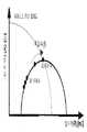
도 5는 본 발명의 일 실시예에 따른, 주파수의 변화에 따른 내부 임피던스를 실수부와 허수부로 표시되는 복소 좌표에 표시한 것이다.
도 6은 본 발명에 따른 배터리의 내부 임피던스 추정 방법의 흐름도를 도시한다.1 is a diagram showing a basic model of a battery by an equivalent circuit.
2 is another diagram showing an equivalent circuit of a basic model of a battery according to an embodiment of the present invention.
3 shows a block diagram of an apparatus for estimating the internal impedance of a battery according to the present invention.
4 is a detailed block diagram of a control unit of the internal impedance estimating apparatus according to the present invention.
FIG. 5 is a graph showing the internal impedance according to a change in frequency in complex coordinates indicated by a real part and an imaginary part, according to an embodiment of the present invention.
FIG. 6 shows a flowchart of a method for estimating internal impedance of a battery according to the present invention.
상술한 본 발명의 특징 및 효과는 첨부된 도면과 관련한 다음의 상세한 설명을 통하여 보다 분명해 질 것이며, 그에 따라 본 발명이 속하는 기술 분야에서 통상의 지식을 가진 자가 본 발명의 기술적 사상을 용이하게 실시할 수 있을 것이다. 본 발명은 다양한 변경을 가할 수 있고 여러가지 형태를 가질 수 있는바, 특정 실시 예들을 도면에 예시하고 본문에 상세하게 설명하고자 한다. 그러나 이는 본 발명을 특정한 개시형태에 대해 한정하려는 것이 아니며, 본 발명의 사상 및 기술범위에 포함되는 모든 변경, 균등물 내지 대체물을 포함하는 것으로 이해되어야 한다. 본 명세서에서 사용한 용어는 단지 특정한 실시 예들을 설명하기 위해 사용된 것으로, 본 발명을 한정하려는 의도가 아니다.BRIEF DESCRIPTION OF THE DRAWINGS The above and other features and advantages of the present invention will become more apparent from the following detailed description of the present invention when taken in conjunction with the accompanying drawings, It will be possible. While the invention is susceptible to various modifications and alternative forms, specific embodiments thereof are shown by way of example in the drawings and are herein described in detail. It is to be understood, however, that the invention is not intended to be limited to the particular forms disclosed, but on the contrary, is intended to cover all modifications, equivalents, and alternatives falling within the spirit and scope of the invention. The terminology used herein is for the purpose of describing particular embodiments only and is not intended to be limiting of the invention.
본 발명은 배터리의 내부 임피던스를 추정하는 방법 및 배터리의 내부 임피던스를 추정하는 장치를 제안한다. 여기서, 내부 임피던스 추정은 배터리의 사용에 따른 배터리의 상태를 구분하기 위한 실시간 또는 준실시간 추정 방법을 포함한다.The present invention proposes a method for estimating the internal impedance of a battery and an apparatus for estimating the internal impedance of the battery. Here, the internal impedance estimation includes a real-time or quasi- real-time estimation method for classifying the state of the battery according to the use of the battery.
이하, 본 발명에 따른 배터리의 내부 임피던스를 추정하는 방법 및 배터리의 내부 임피던스를 추정하는 장치를 도면을 참조하여 보다 상세하게 설명한다.Hereinafter, a method for estimating the internal impedance of the battery and an apparatus for estimating the internal impedance of the battery according to the present invention will be described in detail with reference to the drawings.
도 1은 배터리의 기본 모델을 등가회로(Equivalent Circuit)로 나타낸 도면이다. 도 1에서, Vocv는 개방 회로 전압(open circuit voltage : OCV)을 나타내고, Rs는 직렬등가저항으로 배터리 내부의 전해질의 저항성분과 극판의 저항성분을 표시한 것이다. 저항(Rs)의 값은 충전시에는 높은 SOC에서, 방전시에는 낮은 SOC에서 큰 값을 가지고 그 외 영역의 SOC에서는 일정한 값을 가진다. R-C 병렬 연결로 구성된 과도전위(Overpotential) 부분은 배터리의 충방전시 분극현상을 회로적으로 나타낸 것이다.1 is a diagram showing a basic model of a battery by an equivalent circuit. In FIG. 1, Vocv represents an open circuit voltage (OCV), and Rs represents a series equivalent resistance, which represents the resistance component of the electrolyte inside the battery and the resistance component of the electrode plate. The value of the resistance Rs has a high value at a high SOC at the time of charging, a large value at a low SOC at the time of discharging, and a constant value at the SOC of the other region. The overpotential part composed of the R-C parallel connection is a circuit showing the polarization phenomenon when the battery is charged and discharged.
한편, 도 1에서 도시된 바에 한정되는 것은 아니고, 상기 R-C 병렬 연결은 경우에 따라 R-C 직렬 연결, R-L 병렬 연결, R-L 직렬 연결 및 이들의 임의의 조합을 포함할 수 있다.However, the R-C parallel connection may include an R-C serial connection, an R-L parallel connection, an R-L serial connection, or any combination thereof, as the case may be.
예를 들어, 도 2는 본 발명의 일 실시예에 따른 배터리의 기본 모델을 등가회로로 나타낸 또 다른 도면이다. 예를 들어, 도 2에서, 내부 임피던스는 직렬 등가 저항인 R1, R2-Q2 병렬 임피던스 및 Q3, R3-Q4 병렬 임피던스를 모두 포함한다. 여기서, Q2 및 Q3, Q4는 배터리의 특성 또는 특정 주파수에 따라 인덕턴스 또는 커패시턴스에 해당하는 L 또는 C일 수 있다.For example, FIG. 2 is another diagram showing an equivalent circuit of a basic model of a battery according to an embodiment of the present invention. For example, in FIG. 2, the internal impedance includes both the series equivalent resistors R1, R2-Q2, and the parallel impedance of Q3 and R3-Q4. Here, Q2 and Q3 and Q4 may be L or C corresponding to the inductance or capacitance according to the characteristics of the battery or a specific frequency.
도 3은 본 발명에 따른 배터리의 내부 임피던스를 추정하는 장치의 블록도를 도시한다. 한편, 도 4는 본 발명에 따른 내부 임피던스 추정 장치의 제어부의 상세 블록도를 도시한다.3 shows a block diagram of an apparatus for estimating the internal impedance of a battery according to the present invention. 4 is a detailed block diagram of a controller of the internal impedance estimating apparatus according to the present invention.
도 3을 참조하면, 내부 임피던스 추정 장치(100)는 전원부(110), 전압 측정부(120), 제어부(130) 및 메모리(140)를 포함한다.3, the internal
한편, 도 4를 참조하면, 상기 제어부(130)는 임피던스 연산모듈(131), 임피던스 변화율 판단 모듈(132) 및 배터리 상태 판단 모듈(133)을 더 포함한다.4, the
상기 내부 임피던스 추정 장치(100)의 각 구성부분에 대해 살펴보면 다음과 같다.The components of the internal
상기 전원부(110)는 상기 배터리의 양극 및 음극 단자에 제1주파수의 입력 전압을 인가한다.The
상기 전압 측정부(120)는 상기 입력 전압에 응답하는 상기 배터리의 응답 전압을 상기 양극 및 음극 단자에서 측정한다.The
상기 제어부(130)는 상기 입력 전압의 주파수를 상기 제1주파수보다 일정 주파수 간격만큼 증가된 제2주파수로 증가되도록 제어한다. 또한, 상기 제어부(130)는 상기 제2주파수가 기설정된 주파수 이상인지 여부를 판단한다.The
예를 들어, 상기 제1주파수 및 상기 기설정된 주파수는 각각 1KHz 및 100KHz이고, 상기 일정 주파수 간격은 100Hz일 수 있다.For example, the first frequency and the predetermined frequency may be 1 KHz and 100 KHz, respectively, and the predetermined frequency interval may be 100 Hz.
또한, 상기 제어부(130)는 상기 제2주파수가 상기 기설정된 주파수 이하이면, 상기 제2주파수의 입력 전압을 인가하고 응답 전압을 측정하도록 상기 전원부 및 상기 전압 측정부를 제어한다.The
또한, 상기 제어부(130)는 상기 제2주파수가 상기 기설정된 주파수 이상이면, 다음과 같은 동작을 수행할 수 있다.If the second frequency is equal to or greater than the preset frequency, the
상기 임피던스 연산모듈(131)은 상기 입력 전압의 주파수 변화에 따른 상기 입력 전압 및 상기 응답 전압에 기반하여 상기 배터리의 내부 임피던스를 연산한다. 예를 들어, 도 1을 참조하면, 상기 입력 전압이 Vocv이고, 상기 응답 전압이 Vt이면 상기 내부 임피던스는 Z=Vt/ Vocv에 해당한다. 여기서, 상기 입력 전압과 상기 응답 전압의 위상이 다른 경우, 상기 내부 임피던스 Z는 복소수의 값으로 연산된다.The
상기 임피던스 변화율 판단 모듈(132)은 상기 주파수 변화에 따른 상기 내부 임피던스의 변화율을 연산한다. 또한, 상기 임피던스 변화율 판단 모듈(132)은 주파수 또는 시간의 변화에 따른 임피던스 변화율을 디스플레이부(미도시)에 표시할 수 있다.The impedance change
상기 배터리 상태 판단 모듈(133)은 상기 임피던스 변화율에 기반하여 상기 배터리의 상태를 판단한다.The battery state determination module 133 determines the state of the battery based on the impedance change rate.
상기 메모리(140)는 입력 전압, 응답 전압, 주파수 및 내부 임피던스에 관한 값들을 저장한다. 여기서, 상기 저장된 값들은 시간에 따라 서로 다른 값을 가질 수 있다.The
이와 관련하여, 도 5는 본 발명의 일 실시예에 따른, 주파수의 변화에 따른 내부 임피던스를 실수부와 허수부로 표시되는 복소 좌표에 표시한 것이다.In this regard, FIG. 5 shows the internal impedance according to the change of frequency in the complex coordinates indicated by the real part and the imaginary part, according to an embodiment of the present invention.
도 5a를 참조하면, 제1주파수에서 제2주파수까지는 임피던스의 변화가 작은 반면에, 상기 제2주파수 이상에서 임피던스의 변화가 크다면, 상기 배터리는 제2주파수 이하에서 정상 동작하는 것으로 판단할 수 있다.Referring to FIG. 5A, if the change of the impedance is small from the first frequency to the second frequency and the impedance is changed beyond the second frequency, the battery can be determined to operate normally at the second frequency or less have.
한편, 도5b를 참조하면, 제1주파수에서 제2주파수까지는 임피던스의 절대값이 특정 값 이하인 반면에, 상기 제2주파수 이상에서는 임피던스의 절대값이 특정 값 이상이면, 상기 배터리는 제2주파수 이하에서 정상 동작하는 것으로 판단할 수 있다. 여기서, 임피던스의 절대값은 임피던스의 실수부와 허수부인 저항과 리액턴스 값으로부터 결정된다.5B, when the absolute value of the impedance is equal to or lower than a specific value while the absolute value of the impedance is lower than the specific value from the first frequency to the second frequency, It can be determined that the normal operation is performed. Here, the absolute value of the impedance is determined from the real and imaginary parts of the impedance and the reactance and reactance values.
따라서, 이러한 임피던스의 변화 또는 임피던스의 절대값에 기반하여, 배터리의 상태를 구분할 수 있다.Therefore, the state of the battery can be distinguished based on the change of the impedance or the absolute value of the impedance.
한편, 상기 임피던스 추정 장치에서 전술된 사항들은 아래에서 기술된 임피던스 추정 방법에도 적용될 수 있다.Meanwhile, the above-mentioned matters in the impedance estimation apparatus can be applied to the impedance estimation method described below.
도 6은 본 발명에 따른 배터리의 내부 임피던스 추정 방법의 흐름도를 도시한다. 내부 임피던스 추정 방법은 입력 전압 인가 과정(S610), 응답 전압 측정 과정(S620), 주파수 증가 과정(S630) 및 주파수 판단 과정(S640)을 포함한다. 또한, 상기 내부 임피던스 추정 방법은 임피던스 연산 과정(S650), 임피던스 변화율 판단 과정(S660) 및 배터리 상태 판단 과정(S670)을 더 포함할 수 있다.FIG. 6 shows a flowchart of a method for estimating internal impedance of a battery according to the present invention. The internal impedance estimation method includes an input voltage application step S610, a response voltage measurement step S620, a frequency increase step S630, and a frequency determination step S640. In addition, the internal impedance estimation method may further include an impedance calculation process S650, an impedance change rate determination process S660, and a battery state determination process S670.
상기 입력 전압 인가 과정(S610)은 상기 배터리의 양극 및 음극 단자에 제1주파수의 입력 전압을 인가한다.The input voltage application step S610 applies an input voltage of the first frequency to the positive and negative terminals of the battery.
상기 응답 전압 측정 과정(S620)은 상기 입력 전압에 응답하는 상기 배터리의 응답 전압을 상기 양극 및 음극 단자에서 측정한다.The response voltage measuring step S620 measures a response voltage of the battery in response to the input voltage at the positive and negative terminals.
상기 주파수 증가 과정(S630)은 상기 입력 전압의 주파수를 상기 제1주파수보다 일정 주파수 간격만큼 증가된 제2주파수로 증가시킨다.The frequency increasing step S630 increases the frequency of the input voltage to a second frequency that is increased by a predetermined frequency interval from the first frequency.
상기 주파수 판단 과정(S640)은 상기 제2주파수가 기설정된 주파수 이상인지 여부를 판단한다.The frequency determination step S640 determines whether the second frequency is equal to or greater than a predetermined frequency.
예를 들어, 상기 제1주파수 및 상기 기설정된 주파수는 각각 1KHz 및 100KHz이고, 상기 일정 주파수 간격은 100Hz일 수 있다.For example, the first frequency and the predetermined frequency may be 1 KHz and 100 KHz, respectively, and the predetermined frequency interval may be 100 Hz.
한편, 상기 주파수 판단 과정(S640)에서 상기 제2주파수가 상기 기설정된 주파수 이하이면, 상기 제2주파수의 입력 전압에 대하여 상기 입력 전압 인가 과정 (S610) 및 상기 응답 전압 측정 과정(S620)을 반복수행한다.If the second frequency is equal to or less than the predetermined frequency in the frequency determination step S640, the input voltage application process S610 and the response voltage measurement process S620 are repeated for the input voltage of the second frequency .
상기 임피던스 연산 과정(S650)은 상기 입력 전압의 주파수 변화에 따른 상기 입력 전압 및 상기 응답 전압에 기반하여 상기 배터리의 내부 임피던스를 연산한다.The impedance calculation step S650 calculates the internal impedance of the battery based on the input voltage and the response voltage according to the frequency change of the input voltage.
상기 임피던스 변화율 판단 과정(S660)은 상기 주파수 변화에 따른 상기 내부 임피던스의 변화율을 연산한다.The impedance change rate determination process S660 calculates a change rate of the internal impedance according to the frequency change.
상기 배터리 상태 판단 과정(S670)은 상기 임피던스 변화율에 기반하여 상기 배터리의 상태를 판단한다.The battery state determination process S670 determines the state of the battery based on the impedance change rate.
한편, 상기 임피던스 추정 장치 및 임피던스 추정 방법에서 기술된 사항들은 상호 참조하여 활용될 수 있음은 물론이다.It is needless to say that the matters described in the impedance estimating apparatus and the impedance estimating method can be used by mutual reference.
전술된 본 발명의 실시예들에 따르면, 주파수의 변화에 따라 배터리의 응답 전압을 측정하여, 배터리의 내부 저항을 정확히 측정할 수 있는 장점이 있다.According to the embodiments of the present invention described above, there is an advantage that the internal resistance of the battery can be accurately measured by measuring the response voltage of the battery according to a change in frequency.
또한, 본 발명의 실시예들에 따르면, 외부 조건에 따라 변화하는 배터리의 내부 저항을 실시간 또는 준실시간으로 측정하여, 배터리의 상태를 실시간 또는 준실시간으로 구분할 수 있다는 장점이 있다.In addition, according to embodiments of the present invention, the internal resistance of a battery which changes according to external conditions can be measured in real time or quasi-real time, and the battery can be classified into real time or quasi real time.
한편, 본 발명에서 제시된 배터리의 내부 임피던스를 추정하는 장치는 주파수의 변화에 따라 배터리의 응답 전압을 측정하여 내부 임피던스의 차이를 구하고, 이에 기반하여 배터리의 상태를 판단할 수 있다. 이러한 내부 임피던스의 차이를 구하고, 이에 기반하여 배터리의 상태의 판단은 제어부 또는 프로세서에 의해 생성될 수 있다. 또한, 이러한 제어부 또는 프로세서는 하드웨어, 소프트웨어 및 이들의 조합에 의해 구현될 수 있다.Meanwhile, the apparatus for estimating the internal impedance of the battery proposed in the present invention can determine the state of the battery based on the difference between the internal impedances by measuring the response voltage of the battery according to the change of the frequency. The determination of the state of the battery based on the difference of the internal impedances can be generated by the control unit or the processor. Further, such a control unit or processor may be implemented by hardware, software, and a combination thereof.
소프트웨어적인 구현에 의하면, 본 명세서에서 설명되는 절차 및 기능 뿐만 아니라 각각의 구성 요소들은 별도의 소프트웨어 모듈로도 구현될 수 있다. 상기 소프트웨어 모듈들 각각은 본 명세서에서 설명되는 하나 이상의 기능 및 작동을 수행할 수 있다. 적절한 프로그램 언어로 쓰여진 소프트웨어 어플리케이션으로 소프트웨어 코드가 구현될 수 있다. 상기 소프트웨어 코드는 메모리에 저장되고, 제어부(controller) 또는 프로세서(processor)에 의해 실행될 수 있다.According to a software implementation, not only the procedures and functions described herein, but also each component may be implemented as a separate software module. Each of the software modules may perform one or more of the functions and operations described herein. Software code can be implemented in a software application written in a suitable programming language. The software code is stored in a memory and can be executed by a controller or a processor.
100: 내부 임피던스 추정 장치 110: 전원부
120: 전압 측정부 130: 제어부100: internal impedance estimation device 110:
120: voltage measuring unit 130:
Claims (10)
Translated fromKorean상기 배터리의 양극 및 음극 단자에 제1주파수를 입력 주파수로 하는 입력 전압을 인가하는 입력 전압 인가 과정;
상기 입력 전압에 응답하는 상기 배터리의 응답 전압을 상기 양극 및 음극 단자에서 측정하는 응답 전압 측정 과정;
상기 입력 주파수를 상기 제1주파수보다 일정 주파수 간격만큼 증가된 제2주파수로 증가시키는 주파수 증가 과정; 및
상기 제2주파수가 기설정된 주파수 이상인지 여부를 판단하는 주파수 판단 과정을 포함하고,
상기 주파수 판단 과정의 결과, 상기 제2주파수가 상기 기설정된 주파수 이하이면, 상기 제2주파수를 입력 주파수로 하는 입력 전압에 대하여 상기 입력 전압 인가 과정 및 상기 응답 전압 측정 과정을 다시 수행하고,
상기 주파수 판단 과정의 결과, 상기 제2주파수가 상기 기설정된 주파수 이상이면,
상기 입력 전압의 주파수 변화에 따른 상기 입력 전압 및 상기 응답 전압에 기반하여 상기 배터리의 내부 임피던스를 연산하는 임피던스 연산 과정;
상기 내부 임피던스의 연산 결과를 기초로, 상기 입력 전압의 주파수 변화에 따른 상기 내부 임피던스의 변화율을 연산하는 임피던스 변화율 판단 과정; 및
상기 내부 임피던스 변화율에 기반하여 상기 배터리의 상태를 판단하는 배터리 상태 판단 과정을 더 포함하며,
상기 배터리 상태 판단 과정은, 상기 배터리가, 특정 값 이하인 상기 내부 임피던스 변화율에 상응하는 상기 입력 전압의 주파수 범위 내에서 정상 동작하는 것으로 판단하는 배터리의 내부 임피던스를 추정하는 방법.
A method for estimating an internal impedance of a battery,
An input voltage applying step of applying an input voltage having a first frequency to an anode and a cathode of the battery;
A response voltage measuring step of measuring a response voltage of the battery in response to the input voltage at the positive and negative terminals;
A frequency increasing step of increasing the input frequency to a second frequency increased by a predetermined frequency interval from the first frequency; And
Determining whether the second frequency is equal to or greater than a preset frequency,
Performing the input voltage application process and the response voltage measurement process for an input voltage having the second frequency as an input frequency if the second frequency is equal to or less than the predetermined frequency as a result of the frequency determination process,
As a result of the frequency determination, if the second frequency is equal to or higher than the preset frequency,
Calculating an internal impedance of the battery based on the input voltage and the response voltage according to a frequency change of the input voltage;
An impedance change rate determining step of calculating a rate of change of the internal impedance according to a frequency change of the input voltage based on the calculation result of the internal impedance; And
Further comprising a battery state determining step of determining a state of the battery based on the internal impedance change rate,
Wherein the battery state determining step determines that the battery operates normally within a frequency range of the input voltage corresponding to the internal impedance change rate that is lower than a specific value.
상기 제1주파수 및 상기 기설정된 주파수는 각각 1KHz 및 100KHz이고,
상기 일정 주파수 간격은 100Hz인 것을 특징으로 하는, 배터리의 내부 임피던스를 추정하는 방법.The method according to claim 1,
Wherein the first frequency and the predetermined frequency are 1 KHz and 100 KHz, respectively,
Wherein the predetermined frequency interval is 100 Hz.
상기 배터리의 양극 및 음극 단자에 제1주파수를 입력 주파수로 하는 입력 전압을 인가하는 전원부; 및
상기 입력 전압에 응답하는 상기 배터리의 응답 전압을 상기 양극 및 음극 단자에서 측정하는 전압 측정부; 및
상기 입력 주파수를 상기 제1주파수보다 일정 주파수 간격만큼 증가된 제2주파수로 증가되도록 제어하고, 상기 제2주파수가 기설정된 주파수 이상인지 여부를 판단하여, 상기 제2주파수가 상기 기설정된 주파수 이하이면, 상기 제2주파수를 입력 주파수로 하는 입력 전압을 인가하고 응답 전압을 다시 측정하도록 상기 전원부 및 상기 전압 측정부를 제어하는 제어부를 포함하고,
상기 제어부는,
상기 제2주파수가 상기 기설정된 주파수 이상이면,
상기 입력 전압의 주파수 변화에 따른 상기 입력 전압 및 상기 응답 전압에 기반하여 상기 배터리의 내부 임피던스를 연산하는 임피던스 연산모듈;
상기 내부 임피던스의 연산 결과를 기초로, 상기 입력 전압의 주파수 변화에 따른 상기 내부 임피던스의 변화율을 연산하는 임피던스 변화율 판단 모듈; 및
상기 내부 임피던스 변화율에 기반하여 상기 배터리의 상태를 판단하는 배터리 상태 판단 모듈을 더 포함하며,
상기 배터리 상태 판단 모듈은, 상기 배터리가, 특정 값 이하인 상기 내부 임피던스 변화율에 상응하는 상기 입력 전압의 주파수 범위 내에서 정상 동작하는 것으로 판단하는, 배터리의 내부 임피던스를 추정하는 장치.
An apparatus for estimating an internal impedance of a battery,
A power supply unit for applying an input voltage having a first frequency to an anode and a cathode of the battery; And
A voltage measuring unit for measuring a response voltage of the battery in response to the input voltage at the positive and negative terminals; And
The control unit may control the input frequency to increase to a second frequency that is increased by a predetermined frequency interval from the first frequency to determine whether the second frequency is equal to or greater than a preset frequency, And a control unit for controlling the power unit and the voltage measuring unit to apply an input voltage having the second frequency as an input frequency and measure the response voltage again,
Wherein,
If the second frequency is equal to or higher than the preset frequency,
An impedance calculation module for calculating an internal impedance of the battery based on the input voltage and the response voltage according to a frequency change of the input voltage;
An impedance change rate determination module that calculates a rate of change of the internal impedance according to a frequency change of the input voltage based on the calculation result of the internal impedance; And
And a battery state determination module for determining the state of the battery based on the internal impedance change rate,
Wherein the battery state determination module determines that the battery operates normally within a frequency range of the input voltage corresponding to the internal impedance change rate that is lower than a specific value.
상기 제1주파수 및 상기 기설정된 주파수는 각각 1KHz 및 100KHz이고,
상기 일정 주파수 간격은 100Hz인 것을 특징으로 하는, 배터리의 내부 임피던스를 추정하는 장치.The method according to claim 6,
Wherein the first frequency and the predetermined frequency are 1 KHz and 100 KHz, respectively,
Wherein the predetermined frequency interval is 100 Hz.
Priority Applications (1)
| Application Number | Priority Date | Filing Date | Title |
|---|---|---|---|
| KR1020150154851AKR101759532B1 (en) | 2015-11-05 | 2015-11-05 | A method for estimating an internal impedance of a battery |
Applications Claiming Priority (1)
| Application Number | Priority Date | Filing Date | Title |
|---|---|---|---|
| KR1020150154851AKR101759532B1 (en) | 2015-11-05 | 2015-11-05 | A method for estimating an internal impedance of a battery |
Publications (2)
| Publication Number | Publication Date |
|---|---|
| KR20170052835A KR20170052835A (en) | 2017-05-15 |
| KR101759532B1true KR101759532B1 (en) | 2017-07-19 |
Family
ID=58739559
Family Applications (1)
| Application Number | Title | Priority Date | Filing Date |
|---|---|---|---|
| KR1020150154851AActiveKR101759532B1 (en) | 2015-11-05 | 2015-11-05 | A method for estimating an internal impedance of a battery |
Country Status (1)
| Country | Link |
|---|---|
| KR (1) | KR101759532B1 (en) |
Cited By (1)
| Publication number | Priority date | Publication date | Assignee | Title |
|---|---|---|---|---|
| WO2023080673A1 (en)* | 2021-11-03 | 2023-05-11 | 주식회사 엘지에너지솔루션 | Device and method for estimating impedance spectrum of battery, and system comprising same |
Families Citing this family (4)
| Publication number | Priority date | Publication date | Assignee | Title |
|---|---|---|---|---|
| KR102280292B1 (en)* | 2019-06-13 | 2021-07-21 | 숭실대학교산학협력단 | Method of evaluating impedance spectroscopy for used battery module, recording medium and apparatus for performing the method |
| KR102496569B1 (en)* | 2021-04-13 | 2023-02-06 | 포항공과대학교 산학협력단 | A method and a device for determining impedance characteristics |
| KR20230171658A (en)* | 2022-06-14 | 2023-12-21 | 주식회사 엘지에너지솔루션 | Apparatus and method for estimating battery parameter |
| KR102758918B1 (en)* | 2022-12-26 | 2025-02-03 | (주)배트로닉스 | High-speed measurement device and method for battery ohmic resistance |
Citations (2)
| Publication number | Priority date | Publication date | Assignee | Title |
|---|---|---|---|---|
| JP2004138586A (en)* | 2002-10-21 | 2004-05-13 | Hitachi Ltd | Secondary battery evaluation method and power storage device |
| KR101160545B1 (en) | 2011-01-31 | 2012-06-27 | 주식회사티움리서치 | Apparatus for measuring state of health of rechargeable battery |
- 2015
- 2015-11-05KRKR1020150154851Apatent/KR101759532B1/enactiveActive
Patent Citations (2)
| Publication number | Priority date | Publication date | Assignee | Title |
|---|---|---|---|---|
| JP2004138586A (en)* | 2002-10-21 | 2004-05-13 | Hitachi Ltd | Secondary battery evaluation method and power storage device |
| KR101160545B1 (en) | 2011-01-31 | 2012-06-27 | 주식회사티움리서치 | Apparatus for measuring state of health of rechargeable battery |
Cited By (1)
| Publication number | Priority date | Publication date | Assignee | Title |
|---|---|---|---|---|
| WO2023080673A1 (en)* | 2021-11-03 | 2023-05-11 | 주식회사 엘지에너지솔루션 | Device and method for estimating impedance spectrum of battery, and system comprising same |
Also Published As
| Publication number | Publication date |
|---|---|
| KR20170052835A (en) | 2017-05-15 |
Similar Documents
| Publication | Publication Date | Title |
|---|---|---|
| JP6471179B2 (en) | Insulation resistance measuring apparatus and method capable of quickly measuring insulation resistance | |
| KR101846690B1 (en) | System and Method for Managing Battery on the basis of required time for Charging | |
| TWI752787B (en) | Method and system for evaluating soundness of battery | |
| US9859736B2 (en) | Battery control method based on ageing-adaptive operation window | |
| KR101759532B1 (en) | A method for estimating an internal impedance of a battery | |
| JP6234946B2 (en) | Battery state estimation device | |
| Hossain et al. | A parameter extraction method for the Thevenin equivalent circuit model of Li-ion batteries | |
| CN105203963B (en) | A kind of method of estimation of the state-of-charge based on open-circuit voltage hysteretic characteristic | |
| CN105378498A (en) | State Estimation Method for Electric Storage Device | |
| KR20170092552A (en) | Wireless Network based Battery Management System | |
| JP2019117180A (en) | Battery state estimating device and battery state estimating method | |
| US9891287B2 (en) | Temperature-compensated state of charge estimation for rechargeable batteries | |
| JP6749080B2 (en) | Power storage system, secondary battery control system, and secondary battery control method | |
| TW201539008A (en) | Method and apparatus of estimating state of health of a battery | |
| US10794961B2 (en) | Internal state estimating device | |
| JP2013228216A (en) | Battery dc resistance evaluation device | |
| JP2015108579A (en) | Battery residual capacity estimation device, method of determining battery residual capacity and program of determining battery residual capacity | |
| CN113785209A (en) | Method for detecting abnormal battery cell | |
| KR20150024561A (en) | Battery management system and driving method thereof | |
| CN113945302B (en) | Method and device for determining internal temperature of battery | |
| JP2020125968A (en) | Battery deterioration diagnosis device, battery deterioration analysis circuit, and battery deterioration diagnosis program | |
| CN105277894A (en) | Method and system for estimating state of charge of a battery | |
| JP2016157565A (en) | Battery charging capacity estimation method and battery charging capacity estimation device | |
| CN114137415B (en) | Method and device for detecting heating value of battery pack, vehicle and storage medium | |
| Wong et al. | A new state-of-charge estimation method for valve regulated lead acid batteries |
Legal Events
| Date | Code | Title | Description |
|---|---|---|---|
| A201 | Request for examination | ||
| PA0109 | Patent application | St.27 status event code:A-0-1-A10-A12-nap-PA0109 | |
| PA0201 | Request for examination | St.27 status event code:A-1-2-D10-D11-exm-PA0201 | |
| D13-X000 | Search requested | St.27 status event code:A-1-2-D10-D13-srh-X000 | |
| D14-X000 | Search report completed | St.27 status event code:A-1-2-D10-D14-srh-X000 | |
| E902 | Notification of reason for refusal | ||
| PE0902 | Notice of grounds for rejection | St.27 status event code:A-1-2-D10-D21-exm-PE0902 | |
| T11-X000 | Administrative time limit extension requested | St.27 status event code:U-3-3-T10-T11-oth-X000 | |
| AMND | Amendment | ||
| E13-X000 | Pre-grant limitation requested | St.27 status event code:A-2-3-E10-E13-lim-X000 | |
| P11-X000 | Amendment of application requested | St.27 status event code:A-2-2-P10-P11-nap-X000 | |
| P13-X000 | Application amended | St.27 status event code:A-2-2-P10-P13-nap-X000 | |
| E601 | Decision to refuse application | ||
| PE0601 | Decision on rejection of patent | St.27 status event code:N-2-6-B10-B15-exm-PE0601 | |
| PG1501 | Laying open of application | St.27 status event code:A-1-1-Q10-Q12-nap-PG1501 | |
| T11-X000 | Administrative time limit extension requested | St.27 status event code:U-3-3-T10-T11-oth-X000 | |
| T13-X000 | Administrative time limit extension granted | St.27 status event code:U-3-3-T10-T13-oth-X000 | |
| AMND | Amendment | ||
| P11-X000 | Amendment of application requested | St.27 status event code:A-2-2-P10-P11-nap-X000 | |
| P13-X000 | Application amended | St.27 status event code:A-2-2-P10-P13-nap-X000 | |
| PX0901 | Re-examination | St.27 status event code:A-2-3-E10-E12-rex-PX0901 | |
| PX0701 | Decision of registration after re-examination | St.27 status event code:A-3-4-F10-F13-rex-PX0701 | |
| X701 | Decision to grant (after re-examination) | ||
| GRNT | Written decision to grant | ||
| PR0701 | Registration of establishment | St.27 status event code:A-2-4-F10-F11-exm-PR0701 | |
| PR1002 | Payment of registration fee | St.27 status event code:A-2-2-U10-U11-oth-PR1002 Fee payment year number:1 | |
| PG1601 | Publication of registration | St.27 status event code:A-4-4-Q10-Q13-nap-PG1601 | |
| P22-X000 | Classification modified | St.27 status event code:A-4-4-P10-P22-nap-X000 | |
| P22-X000 | Classification modified | St.27 status event code:A-4-4-P10-P22-nap-X000 | |
| P22-X000 | Classification modified | St.27 status event code:A-4-4-P10-P22-nap-X000 | |
| PR1001 | Payment of annual fee | St.27 status event code:A-4-4-U10-U11-oth-PR1001 Fee payment year number:4 | |
| R18-X000 | Changes to party contact information recorded | St.27 status event code:A-5-5-R10-R18-oth-X000 | |
| S20-X000 | Security interest recorded | St.27 status event code:A-4-4-S10-S20-lic-X000 | |
| PR1001 | Payment of annual fee | St.27 status event code:A-4-4-U10-U11-oth-PR1001 Fee payment year number:5 | |
| PR1001 | Payment of annual fee | St.27 status event code:A-4-4-U10-U11-oth-PR1001 Fee payment year number:6 | |
| PR1001 | Payment of annual fee | St.27 status event code:A-4-4-U10-U11-oth-PR1001 Fee payment year number:7 | |
| PR1001 | Payment of annual fee | St.27 status event code:A-4-4-U10-U11-oth-PR1001 Fee payment year number:8 | |
| R18-X000 | Changes to party contact information recorded | St.27 status event code:A-5-5-R10-R18-oth-X000 | |
| PN2301 | Change of applicant | St.27 status event code:A-5-5-R10-R13-asn-PN2301 St.27 status event code:A-5-5-R10-R11-asn-PN2301 | |
| PR1001 | Payment of annual fee | St.27 status event code:A-4-4-U10-U11-oth-PR1001 Fee payment year number:9 |