KR101759366B1 - Method and apparatus of recovering backhaul link failure between base station and relay node - Google Patents
Method and apparatus of recovering backhaul link failure between base station and relay nodeDownload PDFInfo
- Publication number
- KR101759366B1 KR101759366B1KR1020127020909AKR20127020909AKR101759366B1KR 101759366 B1KR101759366 B1KR 101759366B1KR 1020127020909 AKR1020127020909 AKR 1020127020909AKR 20127020909 AKR20127020909 AKR 20127020909AKR 101759366 B1KR101759366 B1KR 101759366B1
- Authority
- KR
- South Korea
- Prior art keywords
- relay
- relay node
- subframe
- backhaul link
- base station
- Prior art date
- Legal status (The legal status is an assumption and is not a legal conclusion. Google has not performed a legal analysis and makes no representation as to the accuracy of the status listed.)
- Active
Links
Images


Classifications
- H—ELECTRICITY
- H04—ELECTRIC COMMUNICATION TECHNIQUE
- H04W—WIRELESS COMMUNICATION NETWORKS
- H04W24/00—Supervisory, monitoring or testing arrangements
- H04W24/04—Arrangements for maintaining operational condition
- H—ELECTRICITY
- H04—ELECTRIC COMMUNICATION TECHNIQUE
- H04B—TRANSMISSION
- H04B17/00—Monitoring; Testing
- H04B17/40—Monitoring; Testing of relay systems
- H—ELECTRICITY
- H04—ELECTRIC COMMUNICATION TECHNIQUE
- H04W—WIRELESS COMMUNICATION NETWORKS
- H04W76/00—Connection management
- H04W76/10—Connection setup
- H04W76/18—Management of setup rejection or failure
Landscapes
- Engineering & Computer Science (AREA)
- Computer Networks & Wireless Communication (AREA)
- Signal Processing (AREA)
- Physics & Mathematics (AREA)
- Electromagnetism (AREA)
- Mobile Radio Communication Systems (AREA)
Abstract
Translated fromKoreanDescription
Translated fromKorean본 발명은 무선 통신에 관련된 것으로, 더욱 자세하게는 무선 통신 시스템에서 기지국과 중계 노드 사이의 백홀 링크에서의 실패 복구에 관한 것이다.
FIELD OF THE INVENTION The present invention relates to wireless communications, and more particularly to failure recovery on a backhaul link between a base station and a relay node in a wireless communication system.
ITU-R(International Telecommunication Union Radio communication sector)에서는 3세대 이후의 차세대 이동 통신 시스템인 IMT(International Mobile Telecommunication)-Advanced에 대한 표준화 작업을 진행하고 있다. IMT-Adcanced는 고속의 이동 상태에서 100 Mbps, 정지 및 저속의 이동 상태에서 1 Gbps의 데이터 전송률로 인터넷 프로토콜(Internet Protocol: IP) 기반의 멀티미디어 서비스를 지원을 목표로 한다.In the International Telecommunication Union Radio Communication Sector (ITU-R), standardization work on International Mobile Telecommunication (IMT) -Advanced, a next generation mobile communication system after 3rd generation, is underway. IMT-Adcanced aims to support Internet Protocol (IP) based multimedia services at a data rate of 1 Gbps in a moving state of 100 Mbps, a stationary state and a low speed in a high-speed moving state.
3GPP(3rd Generation Partnership Project)는 IMT-Advanced의 요구를 만족시키는 시스템 표준이며, OFDMA(Orthogonal Frequency Division Multiple Access)/SC-FDMA(Single Carrier-Frequency Division Multiple Access) 전송 방식에 기반하여 LTE(Long Term Evolution)의 개선된 LTE-A(LTE-Advanced)를 준비한다. LTE-A는 IMT-Advanced를 위한 유력한 후보 중의 하나이다. LTE-A의 주요 기술에 중계 노드 기술이 포함된다.The 3rd Generation Partnership Project (3GPP) is a system standard that meets the requirements of IMT-Advanced. It is based on Orthogonal Frequency Division Multiple Access (OFDMA) / Single Carrier-Frequency Division Multiple Access (SC-FDMA) Evolution) LTE-Advanced (LTE-Advanced). LTE-A is one of the strong candidates for IMT-Advanced. Major technologies of LTE-A include relay node technology.
중계 노드(Relay Node: RN)는 기지국과 단말(User Equipment: UE) 사이에서 신호를 중계하기 위한 장치로서, 무선 통신 시스템의 셀 커버리지(cell coverage)를 확장하고, 처리율(throughput)을 향상시키기 위해 사용된다.A relay node (RN) is a device for relaying signals between a base station and a user equipment (UE), and is used for extending cell coverage of a wireless communication system and improving throughput Is used.
중계(relaying) 모드(즉, 중계 노드는 백홀 서브프레임(backhaul subframe)에서 기지국으로부터 하향링크 백홀 신호를 수신하고, 액세스 서브프레임(access subframe)에서 해당 중계 UE에 관련 데이터를 전달한다)에서 동작하는 중계 노드는 클럭 표류(clock drift), 채널 정보 피드백 오류, 또는 중계 노드의 재배치와 같은 어떠한 이유로 인해 가끔 백홀 링크 실패를 경험하게 된다. 백홀 링크에서 이러한 링크 실패가 발생하면, 중계 노드는 제어 채널과 데이터 채널을 수신할 수 없으며, 이것은 중계 노드가 UE로 전달되는 데이터를 더 이상 수신할 수 없다는 것을 의미한다.The relay node operates in a relaying mode (i.e., the relay node receives the downlink backhaul signal from the base station in the backhaul subframe and delivers the relevant data to the relay UE in the access subframe) The relay node occasionally experiences a backhaul link failure for some reason, such as clock drift, channel information feedback error, or relay node relocation. If such a link failure occurs on the backhaul link, the relay node can not receive the control channel and the data channel, which means that the relay node can no longer receive the data being delivered to the UE.
중계 노드에 의해서 상술한 백홀 링크 실패를 복구하는 방법이 필요하다.
There is a need for a method of recovering the above-described backhaul link failure by a relay node.
본 발명은 백홀 링크 실패를 복구하는 방법 및 장치를 제공한다.
The present invention provides a method and apparatus for restoring a backhaul link failure.
본 발명의 일 실시예에 따르면, 기지국(Base Station: BS)과 중계 노드(Relay Node) 사이의 백홀 링크 실패를 복구하는 방법이 제공된다. 상기 방법은 중계 노드에 의해 기지국으로부터, 상기 기지국과 상기 중계 노드 사이의 중계 신호를 위해 사용되는 복수의 중계 서브프레임에 관한 정보를 수신하는 단계, 중계 노드에 의해, 상기 복수의 중계 서브프레임을 이용하여 상기 신호를 중계하는 동안 백홀 링크 실패를 검출하는 단계, 상기 백홀 링크 실패가 검출되는 경우, 상기 복수의 중계 서브프레임을 제외한 적어도 하나의 리저브드(reserved) 서브프레임을 결정하는 단계, 및 상기 적어도 하나의 리저브드 서브프레임에서 제어 채널을 통해 상기 백홀 링크 실패를 복구하기 위한 정보를 수신하는 단계를 포함한다.According to an embodiment of the present invention, a method of recovering a backhaul link failure between a base station (BS) and a relay node is provided. The method comprising the steps of: receiving, by a relay node, information about a plurality of relay subframes used for a relay signal between the base station and the relay node from a base station; Determining at least one reserved subframe excluding the plurality of relay subframes when the backhaul link failure is detected, and determining at least one reserved subframe excluding the plurality of relay subframes, And receiving information for recovering the backhaul link failure through a control channel in one reserved subframe.
상기 방법은 상기 중계 노드에 의해 상기 기지국으로부터, 상기 적어도 하나의 리저브드 서브프레임에 관한 정보를 수신하는 단계를 더 포함할 수 있다.The method may further comprise receiving, by the relay node, information about the at least one reserved subframe from the base station.
상기 적어도 하나의 리저브드 서브프레임은 미리 정의될 수 있다.The at least one reserved sub-frame may be predefined.
상기 적어도 하나의 리저브드 서브프레임은 무선 프레임의 첫 번째 및 여섯 번째 서브프레임을 포함할 수 있다.The at least one reserved sub-frame may comprise a first and a sixth sub-frame of a radio frame.
상기 백홀 링크 실패를 복구하기 위한 상기 정보는 데디케이티드 랜덤 액세스 프리앰블(dedicated random access preamble)에 관한 정보를 포함할 수 있다.The information for recovering the backhaul link failure may include information on a dedicated random access preamble.
상기 백홀 링크 실패는 상기 중계 노드가 소정 기간 동안 상기 기지국으로부터 하향링크(Downlink: DL) 제어 신호를 수신하지 않는 경우, 상기 중계 노드가 소정 기간 내에서 상기 기지국으로부터 상향링크(Uplink: UL) 그랜트(grant)를 수신하지 않는 경우, 또는 상기 중계 노드가 소정의 수의 하향링크 데이터 패킷들을 복호화하는 것에 실패하는 경우에 검출될 수 있다.The backhaul link failure may occur when the relay node does not receive a downlink (DL) control signal from the base station for a predetermined period of time, and the relay node receives an uplink (UL) grant grant, or when the relay node fails to decode a predetermined number of downlink data packets.
본 발명의 다른 일 실시예에 따르면, 기지국(Base Staion: BS)과의 백홀 링크 실패를 복구하기 위한 장치가 제공된다. 상기 장치는 무선 신호를 송신 및 수신하는 RF(Radio Frequency)부, 및 상기 RF부에 연결되는 프로세서를 포함한다. 상기 프로세서는 기지국으로부터, 중계 신호를 위해 사용되는 복수의 중계 서브프레임에 관한 정보를 수신하고, 상기 복수의 중계 서브프레임을 이용하여 상기 신호를 중계하는 동안 백홀 링크 실패를 검출하고, 상기 백홀 링크 실패가 검출되는 경우, 상기 복수의 중계 서브프레임을 제외한 적어도 하나의 예약된(reserved) 서브프레임을 결정하고, 및 상기 적어도 하나의 리저브드 서브프레임에서 제어 채널을 통해 상기 백홀 링크 실패를 복구하기 위한 정보를 수신한다.
According to another embodiment of the present invention, there is provided an apparatus for restoring a backhaul link failure with a base station (BS). The apparatus includes a radio frequency (RF) unit for transmitting and receiving a radio signal, and a processor coupled to the RF unit. Wherein the processor is configured to receive from the base station information relating to a plurality of relay subframes used for relay signals and to detect a backhaul link failure while relaying the signals using the plurality of relay subframes, The method comprising the steps of: determining at least one reserved subframe excluding the plurality of relay subframes, and recovering information for restoring the backhaul link failure on the control channel in the at least one reserved subframe .
중계 노드가 일부 또는 모든 서브프레임에서 기지국과 재연결하므로 백홀 링크 실패를 복구할 수 있다.
The relay node may reconnect with the base station in some or all subframes to recover the backhaul link failure.
도 1은 중계국을 포함하는 무선 통신 시스템을 나타낸다.
도 2는 RN을 포함하는 무선 통신 시스템에서 존재하는 링크를 예시한다.
도 3은 3GPP LTE의 무선 프레임(radio frame) 구조를 나타낸다.
도 4는 하나의 하향링크 슬롯에 대한 자원 그리드(resource grid)를 나타낸 예시도이다.
도 5은 하향링크 서브프레임의 구조를 나타낸다.
도 6은 상향링크 서브프레임의 구조를 나타낸다.
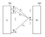
도 7은 MIMO 시스템을 나타낸다.
도 8은 다중 안테나 시스템에서 채널을 나타내는 예이다.
도 9는 노멀(normal) CP에서 4개의 안테나 포트를 지원할 수 있는 RS 구조의 예를 나타낸다.
도 10은 확장(extended) CP에서 4개의 안테나 포트를 지원할 수 있는 RS 구조의 예를 나타낸다.
도 11은 SRS 심볼의 상향링크 서브프레임 구성을 나타낸다.
도 12는 노멀(normal) 서브프레임을 사용하는 중계기-UE 사이의 통신 및 MBSFN(Multi-Media Broadcast over a Single Frequency Network) 서브프레임을 사용하는 eNodeB-중계기 사이의 통신의 예를 나타낸다.
도 13은 백홀 링크 실패에서 RN을 복구하는 방법을 나타내는 순서도다.
도 14는 eNB 서브프레임 인덱스와 RN 서브프레임 인덱스 사이의 관계를 나타낸다.
도 15는 기지국과 중계 노드를 나타내는 블록도이다.1 shows a wireless communication system including a relay station.
Figure 2 illustrates a link existing in a wireless communication system including an RN.
3 shows a radio frame structure of 3GPP LTE.
4 is an exemplary view illustrating a resource grid for one downlink slot.
5 shows the structure of a downlink sub-frame.
6 shows a structure of an uplink sub-frame.
7 shows a MIMO system.
8 shows an example of a channel in a multi-antenna system.
9 shows an example of an RS structure capable of supporting four antenna ports in a normal CP.
10 shows an example of an RS structure capable of supporting four antenna ports in an extended CP.
11 shows an uplink subframe structure of an SRS symbol.
FIG. 12 shows an example of communication between a repeater-UE using a normal subframe and an eNodeB-repeater using a multi-media broadcast over a single frequency network (MBSFN) subframe.
13 is a flowchart illustrating a method of recovering an RN in a backhaul link failure.
14 shows the relationship between the eNB subframe index and the RN subframe index.
15 is a block diagram showing a base station and a relay node.
이하의 기술은 CDMA(code division multiple access), FDMA(frequency division multiple access), TDMA(time division multiple access), OFDMA(orthogonal frequency division multiple access), SC-FDMA(single carrier-frequency division multiple access) 등과 같은 다양한 무선 통신 시스템에서 사용될 수 있다. CDMA 시스템은 UTRA(Universal Terrestrial Radio Access)나 CDMA2000과 같은 무선 기술(radio technology)로 구현될 수 있다. TDMA 시스템은 GSM(Global System for Mobile communications), GPRS(General Packet Radio Service), 또는 EDGE(Enhanced Data Rates for GSM Evolution)와 같은 무선 기술로 구현될 수 있다. OFDMA 시스템은 IEEE(Institute of Electrical and Electronics Engineers) 802.11(Wi-Fi), IEEE 802.16(WiMAX), IEEE 802.20, E-UTRA(Evolved UTRA) 등과 같은 무선 기술로 구현될 수 있다. 3GPP(3rd Generation Partnership Project) LTE(Long Term Evolution)는 E-UTRA를 사용하는 E-UMTS(Evolved UMTS)의 일부이다. 3GPP LTE는 하향링크에서 OFDMA를 채용하고 상향링크에서 SC-FDMA를 채용한다. LTE-A(Advanced)는 3GPP LTE의 진화이다. 이하에서 설명을 명확하게 하기 위해, 3GPP LTE/LTE-A를 예로 설명하나, 본 발명의 기술적 사상이 이에 제한되는 것은 아니다.The following description is to be understood as illustrative and not restrictive, with reference to the accompanying drawings, in which: FIG. 1 is a block diagram of a mobile communication system according to an embodiment of the present invention; And the like. A CDMA system may be implemented with radio technology such as Universal Terrestrial Radio Access (UTRA) or CDMA2000. The TDMA system may be implemented in a wireless technology such as Global System for Mobile communications (GSM), General Packet Radio Service (GPRS), or Enhanced Data Rates for GSM Evolution (EDGE). The OFDMA system can be implemented with wireless technologies such as IEEE (Institute of Electrical and Electronics Engineers) 802.11 (Wi-Fi), IEEE 802.16 (WiMAX), IEEE 802.20, and E-UTRA (Evolved UTRA). 3GPP (Third Generation Partnership Project) LTE (Long Term Evolution) is a part of E-UMTS (Evolved UMTS) using E-UTRA. 3GPP LTE adopts OFDMA in the downlink and SC-FDMA in the uplink. LTE-A (Advanced) is the evolution of 3GPP LTE. For clarity of explanation, 3GPP LTE / LTE-A will be described as an example, but the technical idea of the present invention is not limited thereto.
도 1은 중계국을 포함하는 무선 통신 시스템을 나타낸다.1 shows a wireless communication system including a relay station.
도 1을 참조하면, 무선 통신 시스템(10)은 기지국(11: BS)과 중계 노드(Relay Node: RN)를 포함한다. eNB(11)는 일반적으로 셀(cell)이라고 불리는 지리적 영역(15)에 대해 통신 서비스를 제공한다. 셀은 복수의 영역으로 나누어질 수 있다. 각각의 영역은 섹터(sector)라고 칭한다. 하나 이상의 셀은 기지국(11)에 의해 서비스된다. BS(11)은 단말(User Equipment: UE) 및/또는 RN과 통신하는 고정된 지점(fixed station)을 말하며, eNodeB(evolved-NodeB), BTS(Base Transceiver System), AP(Access Point), 또는 AN(Access Network) 등 다른 용어로 불릴 수 있다. eNB(11)는 RN(12)와 UE(14) 사이의 자원 할당 및 제어, 관리(management), 연결성(connectivity)과 같은 기능을 수행할 수 있다.Referring to FIG. 1, a
RN(120)는 eNB(11)와 UE(14) 사이에서 신호를 중계하는 기기를 말하며, 리피터(repeater) 또는 RS(Relay Station)과 같은 다른 용어로 불릴 수 있다. RB은 AF(amplify and forward) 또는 DF(decode and forward)와 같은 방법을 사용할 수 있지만, 본 발명의 기술적 사상은 이에 제한되지 않는다.The
UE(13, 14)는 고정되거나 이동할 수 있으며, MS(Mobile Station), UT(User Terminal), SS(Subscriber Station), 무선 기기(wireless device), PDA(Personal Digital Assistant), 무선 모뎀(Wireless Modem), 휴대 기기(handheld device) 또는 AT(Access Terminal)와 같은 다른 용어로 불릴 수 있다.The UEs 13 and 14 may be fixed or mobile and may be a mobile station, a user terminal (UT), a subscriber station (SS), a wireless device, a PDA (Personal Digital Assistant), a Wireless Modem ), A handheld device, or an AT (Access Terminal).
이하에서, 매크로 UE(이하 Ma-UE: 13)는 eNB(110)와 직접 통신하는 UE를 말한다. 중계 노드 UE(이하 RN-UE: 14)는 RN과 통신하는 UE를 말한다. eNB(110)의 셀 내에 있는 Ma-UE(13)는 다이버시티(diversity) 효과에 따른 전송 속도의 향상을 위하여 RN(12)를 거쳐서 BS(110)과 통신할 수 있다.Hereinafter, a macro-UE (Ma-UE) 13 refers to a UE directly communicating with the eNB 110. [ The relay node UE (hereinafter referred to as RN-UE) 14 refers to a UE communicating with the RN. The Ma-UE 13 in the cell of the eNB 110 can communicate with the
도 2는 RN을 포함하는 무선 통신 시스템에서 존재하는 링크를 예시한다.Figure 2 illustrates a link existing in a wireless communication system including an RN.
BS와 UE 사이에 RN이 위치하는 무선 통신 시스템에서의 링크는 BS와 UE만 존재하는 무선 통신 시스템에서의 링크와 차이가 있을 수 있다. BS와 UE 사이에서 하향링크는 BS에서 UE로의 통신 링크를 의미하며, 상향링크는 UE에서 BS으로의 통신 링크를 의미한다. TDD(Time division duplex)가 사용되는 경우, 서로 다른 서브프레임에서 하향링크 전송과 상향링크 전송이 수행된다. FDD(frequency division duplex)가 사용되는 경우, 서로 다른 주파수 대역(band)에서 하향링크 전송과 상향링크 전송이 수행된다. TDD에서는 하향링크 전송과 상향링크 전송이 서로 다른 시간 및 동일한 주파수 대역에서 수행될 수 있다. 반면, FDD에서는 하향링크 전송과 상향링크 전송이 동일한 시간에 수행될 수 있으나, 다른 주파수 대역이 사용된다.The link in the wireless communication system where the RN is located between the BS and the UE may differ from the link in the wireless communication system in which only the BS and the UE exist. The downlink between the BS and the UE means a communication link from the BS to the UE, and the uplink means a communication link from the UE to the BS. When time division duplex (TDD) is used, downlink transmission and uplink transmission are performed in different subframes. When frequency division duplex (FDD) is used, downlink transmission and uplink transmission are performed in different frequency bands. In TDD, downlink transmission and uplink transmission can be performed at different times and in the same frequency band. On the other hand, in FDD, downlink transmission and uplink transmission can be performed at the same time, but different frequency bands are used.
BS와 UE 사이에 RN이 포함되는 경우, 상술한 상향링크와 하향링크에 부가하여 백홀 링크와 액세스 링크가 추가될 수 있다.When an RN is included between the BS and the UE, a backhaul link and an access link may be added in addition to the uplink and the downlink.
백홀 링크는 BS와 RN 사이의 통신 링크를 지칭한다. 백홀 하향링크에서, BS는 RN으로 신호를 전송한다. 백홀 상향링크에서, RN는 BS로 신호를 전송한다. 백홀 링크는 Un 인터페이스로 불릴 수도 있다.The backhaul link refers to the communication link between the BS and the RN. On the backhaul downlink, the BS transmits the signal to the RN. On the backhaul uplink, the RN sends a signal to the BS. The backhaul link may also be referred to as the Un interface.
액세스 링크는 RN과 RN에 연결된 UE 사이의 통신 링크를 지칭한다. 액세스 하향링크에서, RN은 UE로 신호를 전송한다. 액세스 상향링크에서, RN-UE는 RN으로 신호를 전송한다. 액세스 링크는 UU 인터페이스로 불릴 수도 있다.The access link refers to the communication link between the RN and the UE connected to the RN. On the access downlink, the RN sends a signal to the UE. On the access uplink, the RN-UE transmits a signal to the RN. The access link may also be referred to as a UU interface.
도 3은 3GPP LTE의 무선 프레임(radio frame) 구조를 나타낸다.3 shows a radio frame structure of 3GPP LTE.
도 3을 참조하면, 무선 프레임(radio frame)은 10개의 서브프레임을 포함하며, 하나의 서브프레임은 2개의 슬롯(slot)을 포함한다. 하나의 서브프레임의 길이는 1ms일 수 있고, 하나의 슬롯의 길이는 0.5ms일 수 있다. 하나의 서브프레임을 전송하는 데 걸리는 시간을 TTI(transmission time interval)라 한다. TTI는 스케줄링(scheduling)의 최소 단위일 수 있다.Referring to FIG. 3, a radio frame includes 10 subframes, and one subframe includes 2 slots. The length of one subframe may be 1 ms, and the length of one slot may be 0.5 ms. The time required to transmit one subframe is referred to as a transmission time interval (TTI). The TTI may be a minimum unit of scheduling.
하나의 슬롯은 시간 영역에서 복수의 하나의 슬롯은 시간 영역에서 복수의 OFDM(orthogonal frequency division multiplexing) 심볼(symbol)을 포함할 수 있다. OFDM 심볼은 3GPP LTE가 하향링크에서 OFDMA를 사용하므로 하나의 심볼 구간(symbol period)을 표현하기 위해 사용하는 것으로 다른 명칭으로 불릴 수 있다. 예를 들어, 상향링크 다중 접속(multi-access) 방법으로 SC-FDMA가 사용될 경우, OFDM 심볼은 SC-FDMA 심볼로 불릴 수 있다. 하나의 슬롯은 7개의 OFDM 심볼을 포함하지만, CP(Cyclic Prefix)의 길이에 따라 하나의 슬롯에 포함되는 OFDM 심볼의 수는 바뀔 수 있다. 3GPP TS 36.211 V8.5.0(2008-12)에 따르면, 노멀(normal) CP에서, 하나의 서브프레임은 7개의 OFDM 심볼을 포함한다. 확장(extended) CP에서, 하나의 서브프레임은 6개의 OFDM 심볼을 포함한다. 무선 프레임의 구조는 예시이며, 무선 프레임에 포함되는 서브프레임의 수와 서브프레임에 포함되는 슬롯의 수는 다양하게 변경될 수 있다. 이하에서 심볼은 하나의 OFDM 심볼 또는 하나의 SC-FDMA 심볼을 의미할 수 있다.One slot may include a plurality of orthogonal frequency division multiplexing (OFDM) symbols in the time domain and a plurality of one slot in the time domain. The OFDM symbol is used to represent one symbol period since 3GPP LTE uses OFDMA in the downlink and may be called another name. For example, when SC-FDMA is used in an uplink multiple access scheme, an OFDM symbol may be referred to as an SC-FDMA symbol. One slot includes 7 OFDM symbols, but the number of OFDM symbols included in one slot may be changed according to the length of a CP (Cyclic Prefix). According to 3GPP TS 36.211 V8.5.0 (2008-12), in a normal CP, one subframe contains seven OFDM symbols. In an extended CP, one subframe contains six OFDM symbols. The structure of the radio frame is an example, and the number of subframes included in the radio frame and the number of slots included in the subframe can be variously changed. Hereinafter, symbols may refer to one OFDM symbol or one SC-FDMA symbol.
도 3을 참조하여 설명한 무선 프레임의 구조는 3GPP TS 36.211 V8.3.0 (2008-05) "Technical Specification Group Radio Access Network; Evolved Universal Terrestrial Radio Access (E-UTRA); Physical Channels and Modulation (Release 8)"의 4.1 절 및 4.2 절을 참조할 수 있다.The structure of the radio frame described with reference to FIG. 3 is described in 3GPP TS 36.211 V8.3.0 (2008-05) "Technical Specification Group Radio Access Network (E-UTRA), Physical Channels and Modulation (Release 8) See Section 4.1 and Section 4.2.
도 4는 하나의 하향링크 슬롯에 대한 자원 그리드(resource grid)를 나타낸 예시도이다.4 is an exemplary view illustrating a resource grid for one downlink slot.
FDD 또는 TDD에서 사용되는 무선 프레임에서, 하나의 슬롯은 시간 영역에서 복수의 OFDM 심볼을 포함하고, 주파수 영역에서 복수의 자원 블록(resource block: RB)을 포함한다. 자원 블록은 자원 할당의 단위로 하나의 슬롯에서 복수의 연속하는 부반송파(subcarrier)를 포함한다.In a radio frame used in FDD or TDD, one slot includes a plurality of OFDM symbols in the time domain and a plurality of resource blocks (RBs) in the frequency domain. A resource block includes a plurality of consecutive subcarriers in one slot in units of resource allocation.
도 4를 참조하면, 하나의 하향링크 슬롯은 7개의 OFDM 심볼을 포함하고, 하나의 자원 블록은 주파수 영역에서 12개의 부반송파를 포함하지만, 이에 제한되는 것은 아니다. 자원 블록에서, 부반송파는 예컨대 15 KHz의 간격을 가질 수 있다.Referring to FIG. 4, one downlink slot includes 7 OFDM symbols, and one resource block includes 12 subcarriers in the frequency domain, but is not limited thereto. In the resource block, the subcarrier may have an interval of 15 KHz, for example.
자원 그리드 상의 각 요소(element)를 자원 요소(resource element)라 하며, 하나의 자원 블록은 12x7개의 자원 요소를 포함한다. 하향링크 슬롯에 포함되는 자원 블록의 수 NDL은 셀에서 설정되는 하향링크 전송 대역폭(bandwidth)에 종속한다. 도 4에서 설명한 자원 그리드는 상향링크에서도 적용될 수 있다.Each element on the resource grid is called a resource element, and one resource block includes 12x7 resource elements. The number of resource blocks NDL included in the downlink slot depends on the downlink transmission bandwidth set in the cell. The resource grid described in Fig. 4 can be applied in the uplink as well.
도 5은 하향링크 서브프레임의 구조를 나타낸다.5 shows the structure of a downlink sub-frame.
도 5를 참조하면, 서브프레임은 2개의 연속적인(consecutive) 슬롯을 포함한다. 서브프레임 내에서 첫 번째 슬롯의 앞선 3개의 OFDM 심볼은 PDCCH(Physical Downlink Control Channel)가 할당되는 제어 영역(control region)에 해당하고, 나머지 OFDM 심볼은 PDSCH(Physical Downlink Shared Channel)가 할당되는 데이터 영역(data region)에 해당한다. 제어 영역에는 PDCCH 이외에도 PCFICH(Physical Control Format Indicator Channel) 및 PHICHI(Physical HARQ Indicator Channel)과 같은 제어 채널이 할당될 수도 있다. UE는 PDCCH를 통해 전송되는 제어 정보를 복호화할 수 있고, PDSCH를 통해 전송되는 데이터 정보를 읽을 수 있다. 여기서, 제어 영역이 3개의 OFDM 심볼을 포함하는 것은 예시에 불과하며, 제어 영역에는 두 개의 OFDM 심볼 또는 하나의 OFDM 심볼이 포함될 수 있다. 서브프레임 내 제어 영역에 포함되는 OFDM 심볼의 수는 PCFICH를 통해 알 수 있다. PHICH는 UE가 전송한 상향링크 데이터에 대한 수신 성공 여부를 나타내는 정보를 나른다. 즉, PHICH는 HARQ ACK(acknowledgment)/NACK(not-acknowledgemnt) 신호를 나른다.Referring to FIG. 5, a subframe includes two consecutive slots. The three OFDM symbols preceding the first slot in the subframe correspond to a control region to which a Physical Downlink Control Channel (PDCCH) is allocated, and the remaining OFDM symbols correspond to a data area allocated to PDSCH (Physical Downlink Shared Channel) (data region). In addition to the PDCCH, a control channel such as a Physical Control Format Indicator Channel (PCFICH) and a Physical HARQ Indicator Channel (PHICHI) may be allocated to the control region. The UE can decode the control information transmitted on the PDCCH and can read the data information transmitted on the PDSCH. Here, it is to be noted that the control region includes only three OFDM symbols, and the control region may include two OFDM symbols or one OFDM symbol. The number of OFDM symbols included in the control region in the subframe can be known through the PCFICH. The PHICH carries information indicating whether reception of the uplink data transmitted by the UE is successful. That is, the PHICH carries an HARQ ACK (acknowledgment) / NACK (not-acknowledgment) signal.
PDCCH를 통해 전송되는 제어 정보를 하향링크 제어 정보(downlink control information: 이하 DCI)라고 한다. DCI는 상향링크 스케줄링 정보, 하향링크 스케줄링 정보, 시스템 정보(system information), 상향링크 전력 제어 명령(power control command), 페이징(paging)을 위한 제어 정보, 랜덤 액세스 응답(RACH response)을 지시하기 위한 제어정보 등을 포함한다.The control information transmitted through the PDCCH is referred to as downlink control information (DCI). DCI is used to indicate uplink scheduling information, downlink scheduling information, system information, uplink power control commands, control information for paging, and a random access response (RACH response) Control information, and the like.
제어 영역은 복수의 CCE(control channel elements)를 포함한다. CCE 열은 하나의 서브프레임 내에서 제어 영역을 구성하는 모든 CCE의 집합이다. CCE는 복수의 자원 요소 그룹(Resource Element Group: REG)를 포함한다. 예를 들어, CCE는 9개의 REG를 포함할 수 있다. REG는 제어 채널을 자원 요소에 맵핑하는 것을 정의하기 위해 사용된다. 예를 들어 하나의 REG는 4개의 자원 요소를 포함할 수 있다.The control region includes a plurality of control channel elements (CCEs). The CCE column is a set of all CCEs constituting the control region in one subframe. The CCE includes a plurality of Resource Element Groups (REGs). For example, a CCE may contain nine REGs. REG is used to define the mapping of control channels to resource elements. For example, one REG may contain four resource elements.
PDCCH는 전송 포맷, 하향링크 공유 채널(Downlink Shared Channel: DL-SCH)의 자원 할당, 상향링크 공유 채널(Uplink Shared Channel: UL-SCH)의 자원 할당 정보, 페이징 채널(Paging Channel: PCH)에 관한 페이징 정보, DL-SCH에 관한 시스템 정보, PDSCH를 통해 전송되는 랜덤 액세스 응답과 같은 상위 계층 제어 메시지의 자원 할당, 임의의 UE 그룹에서 각각의 UE에 대한 전송 전력 제어 명령의 집합, 전송 출력 제어 명령, VoIP(Voice over IP)의 활성화(activation) 등을 나를 수 있다.The PDCCH includes a transport format, a resource allocation of a downlink shared channel (DL-SCH), a resource allocation information of an uplink shared channel (UL-SCH), and a paging channel (PCH) Resource allocation of upper layer control messages such as paging information, system information about DL-SCH, random access response transmitted through the PDSCH, set of transmission power control commands for each UE in a certain UE group, , Activation of VoIP (Voice over IP), and the like.
복수의 PDCCH는 제어 영역 내에서 전송될 수 있다. PDCH는 스케줄링 할당과 같은 제어 정보(control information)를 나른다. PDCCH는 하나의 CCE 또는 몇몇의 연속적인 CCE의 애그리게이션(aggregation)을 통해 전송된다. CCE 애그리게이션을 구성하는 CCE의 수에 따라 PDCCH의 포맷 및 사용 가능(available)한 PDCCH의 비트 수가 결정된다. PDCCH 전송을 위해 사용되는 CCE의 수를 CCE 애그리게이션 레벨(CCE aggregation level)이라 한다. 또한, CCE 애그리게이션 레벨은 PDCCH를 검색하기 위한 CCE 단위이다. CCE 애그리게이션 레벨의 크기는 인접하는(contiguous) CCE의 수에 의해 결정된다. 예를 들어, CCE 애그리게이션 레벨은 {1, 2, 4, 8}의 원소일 수 있다.A plurality of PDCCHs may be transmitted in the control domain. The PDCH carries control information such as scheduling assignment. The PDCCH is transmitted through an aggregation of one CCE or several consecutive CCEs. The format of the PDCCH and the number of bits of the available PDCCH are determined according to the number of CCEs constituting the CCE aggregation. The number of CCEs used for PDCCH transmission is called a CCE aggregation level. Also, the CCE aggregation level is a CCE unit for searching the PDCCH. The size of the CCE aggregation level is determined by the number of contiguous CCEs. For example, the CCE aggregation level may be an element of {1, 2, 4, 8}.
BS는 UE로 전송되는 DCI에 따라 PDCCH 포맷을 결정하고, 정보를 제어하기 위해 CRC(Cyclic Redundancy Check)를 부가한다. CRC는 PDCCH의 용법(usage) 또는 소유자(owner)에 따라 RNTI(Radio Network Temporary Identifier)로 불리는 고유의 식별자(identifier)로 마스크(mask)된다. PDCCH가 특정 UE에 대한 것이라면, UE의 C-RNTI(Cell-RNTI)와 같은 고유의 식별자는 CRC로 마스크될 수 있다. 또는, PDCCH가 페이징 메시지에 대한 것이라면, P-RNTI(paing-RNTI)와 같은 페이징 지시자 식별자는 CRC로 마스크될 수 있다. PDCCH가 시스템 정보, 더욱 구체적으로, 시스템 정보 블록(System Information Block: SIB)에 대한 것이라면, 시스템 정보 식별자와 SI-RNTI(System Information)은 CRC로 마스크될 수 있다. UE의 랜덤 액세스 프리앰블의 전송에 대한 응답인 랜덤 액세스 응답을 지시하기 위해, RA-RNTI(Random Access-RNTI)는 CRC로 마스크될 수 있다.The BS determines the PDCCH format according to the DCI transmitted to the UE and adds a CRC (Cyclic Redundancy Check) to control the information. The CRC is masked with a unique identifier called Radio Network Temporary Identifier (RNTI) according to the usage or owner of the PDCCH. If the PDCCH is for a particular UE, a unique identifier such as the UE's C-RNTI (Cell-RNTI) may be masked with a CRC. Alternatively, if the PDCCH is for a paging message, a paging indicator identifier such as a p-RNTI (p-RNTI) may be masked with a CRC. The system information identifier and SI-RNTI (System Information) may be masked with a CRC if the PDCCH is for system information, more specifically, a system information block (SIB). To indicate a random access response that is a response to the transmission of the UE's random access preamble, a Random Access-RNTI (RA-RNTI) may be masked with a CRC.
도 6은 상향링크 서브프레임의 구조를 나타낸다.6 shows a structure of an uplink sub-frame.
도 6을 참조하면, 상향링크 서브프레임은 주파수 영역에서, 상향링크 제어 정보를 나르는 PUCCH(Physical Uplink Control Channel)가 할당되는 제어 영역(control region)과 사용자 데이터를 나르는 PUSCH(Physical Uplink Shared Channel)가 할당되는 데이터 영역으로 나눌 수 있다.Referring to FIG. 6, in a frequency domain, an uplink subframe includes a control region in which a Physical Uplink Control Channel (PUCCH) for carrying uplink control information is allocated, and a Physical Uplink Shared Channel (PUSCH) And can be divided into data areas to be allocated.
하나의 UE에 대한 PUCCH는 서브프레임에서 자원 블록(Resource Block: RB) 쌍(pair: 51, 52) 형태로 할당되고, RB 쌍에 속하는 RB(51, 52)는 2개의 슬롯에서 서로 다른 부반송파를 차지한다. 이를 PUCCH에 할당되는 RB 쌍이 슬롯 경계(slot boundary)에서 주파수 도약(frequency hopping)된다고 한다.The PUCCH for one UE is allocated in the form of resource blocks (RBs) 51 and 52 in a subframe and the RBs 51 and 52 belonging to the RB pair allocate different subcarriers in two slots Occupies. It is assumed that the RB pair allocated to the PUCCH is frequency hopped at the slot boundary.
PUCCH는 여러 포맷을 지원할 수 있다. 즉, PUCCH는 변조 방식(modualtion scheme)에 따라 서브프레임당 서로 다른 비트수를 갖는 상향링크 제어 정보를 전송할 수 있다. 예를 들어, BPSK(Binary Phase Shift Keying)가 사용되는 경우(즉, PUCCH 포맷 1a), 1 비트의 상향링크 제어 정보가 PUCCH을 통해 전송될 수 있다. QPSK(Quadrature Phase Shift Keying)가 사용되는 경우(즉, PUCCH 포맷 1b), 2 비트의 상향링크 제어 정보가 PUCCH을 통해 전송될 수 있다. PUCCH 포맷은 상술한 포맷 이외에도 포맷 1, 포맷 2, 포맷 2a, 포맷 2b이 있다(PUCCH 포맷은 3GPP TS 36.211 V8.2.0 (2008-03) "Technical Specification Group Radio Access Network; Evolved Universal Terrestrial Radio Access (E-UTRA); Physical Channels and Modulation (Release 8)"의 5.4절을 참조할 수 있다).PUCCH can support multiple formats. That is, the PUCCH can transmit uplink control information having a different number of bits per subframe according to a modulation scheme. For example, when Binary Phase Shift Keying (BPSK) is used (i.e., PUCCH format 1a), one bit of uplink control information can be transmitted via the PUCCH. When QPSK (Quadrature Phase Shift Keying) is used (i.e., PUCCH format 1b), uplink control information of 2 bits can be transmitted on the PUCCH. The PUCCH format includes
무선통신 시스템, 예컨대 도 1에서 설명한 무선통신 시스템은 MIMO(Multi-Input Multi-Output) 기술을 사용하는 시스템, 즉 MIMO 시스템일 수 있다. MIMO 기술은 하나의 송신 안테나와 하나의 수신 안테나를 사용했던 것에서 탈피해 다중 송신 안테나와 다중 수신 안테나를 채택함으로써 송수신 데이터의 전송 효율을 향상시킨다. 즉, MIMO 기술은 무선 통신 시스템의 송신기 또는 수신기에서 복수의 안테나를 사용한다. MIMO 기술을 사용하면, 무선 통신 시스템의 성능과 통신 용량을 개선시킬 수 있다. MIMO 시스템은 다중안테나(multi-antenna) 시스템으로도 불린다. MIMO 기술은 하나의 전체 메시지를 수신하기 위해 단일 안테나 경로에 의존하지 않고, 여러 안테나에서 수신된 데이터를 모아서 완성하는 기술을 응용한 것이다. 결과적으로, 특정 범위에서 데이터 전송 속도를 향상시키거나, 특정 데이터 전송 속도에 대한 시스템 범위를 증가시킬 수 있다.The wireless communication system, e.g., the wireless communication system described in FIG. 1, may be a system using Multi-Input Multi-Output (MIMO) technology, i.e., a MIMO system. The MIMO technique improves the transmission efficiency of the transmission / reception data by adopting the multiple transmission antennas and the multiple reception antennas by avoiding the use of one transmission antenna and one reception antenna. That is, the MIMO technique uses a plurality of antennas in a transmitter or a receiver of a wireless communication system. The use of MIMO technology can improve the performance and communication capacity of a wireless communication system. A MIMO system is also referred to as a multi-antenna system. The MIMO technique applies a technique of collecting and completing data received from various antennas without relying on a single antenna path to receive a whole message. As a result, it is possible to improve the data transmission speed in a certain range or increase the system range for a specific data transmission speed.
차세대 이동 통신 기술은 종래의 이동 통신 기술보다 높은 데이터 전송율을 요구한다. 따라서, MIMO 기술은 차세대 이동 통신 기술에 필수적이라고 할 수 있다. MIMO 기술은 데이터 전송율의 한계를 극복하기 위해 BS뿐만 아니라 UE 또는 RN에 적용될 수 있다. 또한, MIMO 기술은 추가적인 주파수 대역을 사용하거나 추가적인 전송 전력을 요구하지 않고 데이터 전송 효율을 개선할 수 있다는 기술적 장점이 있으므로 다른 기술보다 주목을 받고 있다.Next generation mobile communication technology requires higher data transfer rate than conventional mobile communication technology. Therefore, MIMO technology is essential for next generation mobile communication technology. The MIMO technique can be applied not only to the BS but also to the UE or RN to overcome the limit of the data rate. In addition, MIMO technology is attracting more attention than other technologies because it has the technical advantage of using an additional frequency band or improving the data transmission efficiency without requiring additional transmission power.
먼저, MIMO 시스템의 수학적 모델링에 대해 설명한다.First, mathematical modeling of a MIMO system is described.
도 7은 MIMO 시스템을 나타낸다.7 shows a MIMO system.
도 7을 참조하면, 송신기(Tx: 700)는 NT개의 송신 안테나를 가지고, 수신기(Rx: 800)는 NR개의 수신 안테나를 가진다. 이러한 경우, 이론적 채널 전송 용량은 안테나의 수에 비례하여 증가한다.Referring to FIG. 7, a transmitter (Tx) 700 has NT transmit antennas and a
채널 전송 용량의 증에 의해 얻어지는 전송률은 단일 안테나를 사용하는 경우에 이론적으로 얻어지는 최대 전송률(R0)과 다중 안테나를 사용하는 경우 발생하는 증가율(Ri)의 곱으로 나타낼 수 있다. 증가율(Ri)은 다음의 수학식과 같이 나타낼 수 있다.The transmission rate obtained by increasing the channel transmission capacity can be expressed as a product of a maximum transmission rate (R0 ) theoretically obtained when a single antenna is used and a multiplication rate (Ri ) generated when multiple antennas are used. The rate of increase (Ri ) can be expressed by the following equation.

전송 정보는 송신 안테나의 개수가 NT개인 경우 최대 NT개의 다른 정보를 포함할 수 있다. 이러한 경우, 전송 정보는 다음의 수학식 2와 같이 나타낼 수 있다.The transmission information may include up to NT different information if the number of transmit antennas is NT. In this case, the transmission information can be expressed by the following equation (2).

수학식 2에서s는 전송 정보 벡터를 나타내고, s1, s2, …, sNT는 각각의 정보를 나타낸다(즉, 전송 정보 벡터의 각각의 요소). 각각의 정보는 서로 다른 전송 전력으로 전송될 수 있다. 전송 전력을 (P1, P2, …, PNT)로 표시하는 경우, 전송 전력이 적용된 전송 정보 벡터는 다음의 수학식 3과 같이 나타낼 수 있다.In Equation (2),s denotes a transmission information vector, s1 , s2 , ... , sNT denote the respective information (i. e., each element of the transmission information vector). Each piece of information can be transmitted with different transmission power. When the transmission power is represented by (P1 , P2 , ..., PNT ), the transmission information vector to which the transmission power is applied can be expressed by the following Equation (3).

수학식 3은 다음의 수학식 4와 같이 전송 전력 대각 행렬(transmission power diagonal matrix)과 전송 정보 벡터의 곱으로 표시할 수 있다.Equation (3) can be expressed as a product of a transmission power diagonal matrix and a transmission information vector as shown in Equation (4).

전송 전력이 적용된 전송 정보 벡터

수학식 5에서, 가중치 행렬의 요소 wij(1=i=NT, 1=j=NT)는 i번째 송신 안테나, j번째 전송 정보에 대한 가중치를 나타낸다. 가중치 행렬 W는 프리코딩 행렬(precoding matrix)이라 칭하기도 한다.In Equation (5), the elements wij (1 = i = NT , 1 = j = NT ) denotes a weight for the i-th transmit antenna and the j-th transmit information. The weighting matrix W may also be referred to as a precoding matrix.
전송 신호 벡터는 전송 방식에 따라 다른 전송 정보를 포함할 수 있다. 예를 들어, 공간 다이버시티(spatial diversity), 즉 전송 다이버시티가 적용되는 경우, 전송 신호 벡터의 전송 정보는 모두 동일할 수 있다. 즉, [s1, s2, …, snT]는 모두 동일한 정보, 예컨대 [s1, s1, …, s1 ]일 수 있다. 동일한 전송 정보가 서로 다른 채널을 통해 수신기로 전송되므로, 다이버시티 효과 및 전송의 신뢰도가 증가한다.The transmission signal vector may include other transmission information depending on the transmission scheme. For example, when spatial diversity, i.e., transmit diversity, is applied, the transmission information of the transmission signal vector may all be the same. That is, [s1 , s2 , ... , snT ] are all the same information, e.g., [s1 , s1 , ... , s1 ]. Since the same transmission information is transmitted to the receiver through different channels, diversity effect and transmission reliability are increased.
다른 예를 들어, 공간 다중화가 적용되는 경우, 전송 신호 벡터의 전송 정보는 서로 다를 수 있다. 즉, s1, s2, …, snT는 서로 다른 정보일 수 있다. 서로 다른 전송 정보가 서로 다른 채널을 통해 전송되므로, 전송 정보량이 증가한다는 장점이 있다.As another example, when spatial multiplexing is applied, the transmission information of the transmission signal vector may be different from each other. That is, s1 , s2 , ... , snT may be different information. Since the different transmission information is transmitted through different channels, there is an advantage that the amount of transmission information increases.
또한, 공간 다이버시티와 공간 다중화를 함께 사용하여 전송 정보를 전송할 수도 있다. 즉, 상술한 예에서 동일한 정보가 공간 다이버시티에 따라 3개의 송신 안테나를 통해 전송되고, 서로 다른 정보가 공간 다중화에 따라 나머지 송신 안테나를 통해 전송될 수 있다. 이러한 경우, 전송 정보 벡터는 [s1, s1, s1, s2, s3, …, snT-2]과 같이 구성될 수 있다.In addition, transmission information can be transmitted by using spatial diversity and spatial multiplexing together. That is, in the above example, the same information is transmitted through three transmission antennas according to spatial diversity, and different information can be transmitted through the remaining transmission antennas according to spatial multiplexing. In this case, the transmission information vector is [s1 , s1 , s1 , s2 , s3 , ... , snT-2 ].
수신기의 수신 안테나의 수가 NR개인 경우, 각각의 수신 안테나에서 수신되는 신호를 yn(1≤n≤NR)이라고 표시할 수 있다. 여기서, 수신 신호 벡터y는 다음의 수학식과 같이 나타낼 수 있다.If the number of receiving antennas in the receiver is NR , the signal received at each receiving antenna can be denoted by yn (1 ≤n ≤ NR ). Here, the received signal vectory can be expressed by the following equation.

MIMO 시스템에서 채널 모델링이 수행되는 경우, 각각의 채널은 송신 안테나의 인덱스와 수신 안테나의 인덱스에 기반하여 구분될 수 있다. 송신 안테나의 인덱스를 j라 하고, 수신 안테나의 인덱스를 i라 하면, 송신 안테나와 수신 안테나 사이의 채널을 hij로 표시할 수 있다(채널을 표시하는 첨자에서, 수신 안테나의 인덱스가 먼저 표시되고, 송신 안테나의 인덱스가 나중에 표시되는 것에 주의해야 한다.)When channel modeling is performed in a MIMO system, each channel can be distinguished based on the index of the transmit antenna and the index of the receive antenna. If the index of the transmitting antenna is j and the index of the receiving antenna is i, the channel between the transmitting antenna and the receiving antenna can be represented by hij (in the subscript indicating the channel, the index of the receiving antenna is displayed first, Note that the index of the transmit antenna is displayed later.)
도 8은 다중 안테나 시스템에서 채널을 나타내는 예이다.8 shows an example of a channel in a multi-antenna system.
도 8을 참조하면, NT개의 송신 안테나 각각과 수신 안테나 i에 대한 채널은 hi1, hi2, …, hiNT로 표시된다. 편의상 채널을 행렬이나 벡터로 나타낼 수 있다. 이러한 경우, 채널 hi1, hi2, …, hiNT은 다음의 수학식과 같이 벡터 형태로 나타낼 수 있다.Referring to FIG. 8, the channels for each of the NT transmit antennas and the receive antenna i are denoted by hi1 , hi2 , .... , hiNT . For convenience, the channel can be represented by a matrix or vector. In this case, the channels hi1 , hi2 , ... , hiNT can be represented as a vector form as shown in the following equation.

NT개의 송신 안테나에서 NR개의 수신 안테나로의 모든 채널을 행렬 형태로 나타낸 것을 채널 행렬H라 하면,H는 다음의 수학식 8과 같이 나타낼 수 있다.Assuming that all the channels from the NT transmit antennas to the NR receive antennas are represented in a matrix form as a channel matrixH ,H can be expressed as Equation (8).

송신 안테나에서 전송되는 신호는 수학식 8과 같은 채널을 통해 수신 안테나에서 수신된다. 여기서, 실제의 채널에서는 잡음(noise)이 추가된다. 이러한 잡음은 수학적으로 AWGN(Additive White Gaussian Noise)로서 고려될 수 있다. 각각의 수신 안테나에 추가되는 AWGN을 각각 n1, n2, …, nNR이라 표시하면, 편의상 이러한 AWGN은 다음의 수학식과 같은 벡터로 표시될 수 있다.The signal transmitted from the transmitting antenna is received at the receiving antenna through the channel as shown in Equation (8). Here, noise is added to the actual channel. This noise can be mathematically considered as AWGN (Additive White Gaussian Noise). AWGNs added to each receive antenna are denoted by n1 , n2 , ... , nNR , then for convenience this AWGN can be represented by a vector such as:

수신 안테나에서 수신되는 수신 신호 벡터y는 상술한 AWGN, 전송 신호 벡터x,채널 행렬 등을 고려하여 다음의 수학식과 같이 나타낼 수 있다.The reception signal vectory received at the reception antenna can be expressed by the following equation in consideration of the AWGN, transmission signal vectorx, channel matrix, and the like.

채널 행렬H에서, 행의 수와 열의 수는 송신 안테나의 수와 수신 안테나의 수에 따라 결정된다. 채널 행렬H에서, 행의 수는 수신 안테나의 수와 같다. 또한, 채널 행렬H에서, 열의 수는 송신 안테나의 수와 같다. 따라서, 채널 행렬H는 NR x NT 행렬로 나타낼 수 있다.In the channel matrixH , the number of rows and the number of columns are determined according to the number of transmission antennas and the number of reception antennas. In channel matrixH , the number of rows equals the number of receive antennas. Also, in the channel matrixH , the number of columns equals the number of transmit antennas. Therefore, the channel matrixH can be represented by an NR x NT matrix.
일반적으로, 행렬의 랭크(rank)는 독립 행(independent row)의 수와 독립 열(independent column)의 수 중에서 작은 수로 정의된다. 따라서, 행렬의 랭크는 열의 수나 행의 수보다 클 수는 없으며, 채널 행렬H의 랭크는 다음의 수학식과 같이 결정된다.In general, the rank of a matrix is defined as the number of independent rows and the number of independent columns. Therefore, the rank of the matrixH can not be greater than the number of columns or the number of rows, and the rank of the channel matrixH is determined according to the following equation.

일반적으로, 전송 정보, 예컨대 데이터는 무선 채널을 통해 전송되는 동안 쉽게 왜곡 또는 변경된다. 따라서, 이러한 오류 없이 전송 정보를 복조하기 위해서는 참조 신호가 필요하다. 참조 신호는 송신기와 수신기 모두에 미리 알려진 신호로서 전송 정보와 함께 전송된다. 송신기로부터 전송되는 전송 정보는 각각의 송신 안테나 또는 각각의 계층(layer)에 대응하는 채널을 겪으므로(experience), 참조 신호는 각각의 송신 안테나 또는 계층에 할당될 수 있다. 각각의 송신 안테나 또는 계층에 할당되는 참조 신호는 시간, 주파수 및 코드(code) 등의 자원(resource)에 기반하여 서로 구별될 수 있다. 참조 신호는 2 가지 목적, 즉 전송 정보의 복조와 채널 추정(estimation)을 위해 사용될 수 있다.Generally, transmission information, e.g., data, is easily distorted or changed while being transmitted over a wireless channel. Therefore, a reference signal is needed to demodulate the transmission information without error. The reference signal is transmitted together with transmission information as a known signal to both the transmitter and the receiver. Since the transmission information transmitted from the transmitter experiences a channel corresponding to each transmission antenna or each layer, a reference signal can be assigned to each transmission antenna or layer. The reference signals allocated to each transmission antenna or layer can be distinguished from each other based on resources such as time, frequency and code. The reference signal can be used for two purposes: demodulation of transmission information and channel estimation.
참조 신호는 참조 신호를 미리 알고 있는 수신기의 범위에 따라 2가지 종류로 나뉠 수 있다. 첫 번째 종류의 참조 신호는 특정 수신기(예컨대, 특정 UE)가 알고 있는 참조 신호이다. 이러한 참조 신호를 데디케이티드 참조 신호(Dedicated Reference Signal: 이하 DRS라 함)라 한다. 이러한 의미에서, DRS를 UE 특정적 참조 신호(UE-specific RS)라고도 한다. 두 번째 종류의 참조 신호는 셀 내의 모든 수신기(예컨대, 모든 UE)가 알고 있는 참조 신호이다. 이러한 참조 신호를 공용 참조 신호(Common RS: 이하 CRS라 함)라 한다. CRS를 셀 특정적 참조 신호(cell-specific RS)라고도 한다.The reference signal can be divided into two types according to the range of the receiver which knows the reference signal in advance. The first type of reference signal is a reference signal known to a particular receiver (e.g., a particular UE). This reference signal is called a Dedicated Reference Signal (DRS). In this sense, DRS is also referred to as UE-specific RS. The second type of reference signal is a reference signal known to all receivers (e.g., all UEs) in a cell. This reference signal is referred to as a common RS (hereinafter referred to as CRS). CRS is also referred to as a cell-specific RS.
또한, 참조 신호는 용도에 따라 분류될 수 있다. 예를 들어, 데이터를 복조(demodulate)하기 위해 사용되는 참조 신호를 복조 참조 신호(Demodulation Reference Signal: 이하 DM-RS라 함)라 한다. CQI, PMI, IR와 같이, 채널 상태를 나타내는 피드백 정보를 위해 사용되는 참조 신호를 채널 상태 지시자 참조 신호(Channel State Indicator-RS: 이하 CSI-RS)라 한다. 상기 DRS는 DM-RS로 사용될 수 있다. 이하, DM-RS는 DRS임을 전제로 한다.Also, the reference signal can be classified according to the use. For example, a reference signal used for demodulating data is referred to as a demodulation reference signal (DM-RS). A reference signal used for feedback information indicating a channel state, such as CQI, PMI, and IR, is referred to as a Channel State Indicator-RS (CSI-RS). The DRS may be used as a DM-RS. Hereinafter, it is assumed that the DM-RS is DRS.
도 9는 노멀(normal) CP에서 4개의 안테나 포트를 지원할 수 있는 RS 구조의 예를 나타낸다. 도 10은 확장(extended) CP에서 4개의 안테나 포트를 지원할 수 있는 RS 구조의 예를 나타낸다. 도 9 및 10의 RS 구조는 종래의 3GPP LTE 시스템에서 사용되는 RS 구조이다.9 shows an example of an RS structure capable of supporting four antenna ports in a normal CP. 10 shows an example of an RS structure capable of supporting four antenna ports in an extended CP. The RS structure of FIGS. 9 and 10 is an RS structure used in a conventional 3GPP LTE system.
도 9 및 10에서, 0 내지 3 중 어느 하나의 숫자가 표시된 자원 요소는 셀 특정적 참조 신호(즉, CRS)가 전송되는 자원 요소를 나타낸다. 여기서, 0 내지 3 중 어느 하나의 숫자는 지원하는 안테나 포트를 나타낸다. 즉, #i(i는 0 내지 3 중 어느 하나)가 표시된 자원 요소는 안테나 포트 #i에 대한 CRS가 맵핑되는 자원 요소이다. CRS는 각각의 안테나 포트에 대한 채널 측정 및 데이터 복조를 위해 사용된다. CRS는 서브프레임의 제어 영역 및 데이터 영역에서 모두 전송된다.In FIGS. 9 and 10, a resource element in which any one of 0 to 3 is indicated represents a resource element to which a cell-specific reference signal (i.e., CRS) is transmitted. Here, any one of 0 to 3 represents a supported antenna port. That is, the resource element indicated by #i (i is any one of 0 to 3) is a resource element to which the CRS for the antenna port #i is mapped. The CRS is used for channel measurement and data demodulation for each antenna port. The CRS is transmitted in both the control region and the data region of the subframe.
도 9 및 도 10에서, D가 표시된 자원 요소는 UE 특정적 참조 신호(즉, DRS)가 맵핑되는 자원 요소를 나타낸다. UE 특정적 참조 신호는 PDSCH의 단일 안테나 포트의 전송에 사용될 수 있다. UE는 PDSCH가 전송되는 경우 UE 특정적 참조 신호가 유효한지 여부 및 UE 특정적 참조 신호가 전송되는지 여부를 상위 계층 시그널링을 통해 지시 받는다. UE 특정적 참조 신호는 데이터 복조가 필요한 경우에만 전송될 수 있다. UE 특정적 참조 신호는 서브프레임의 데이터 영역에서만 전송될 수 있다.In FIGS. 9 and 10, a resource element denoted D represents a resource element to which a UE specific reference signal (i.e., DRS) is mapped. The UE specific reference signal may be used for transmission of a single antenna port of the PDSCH. The UE is instructed via upper layer signaling whether the UE specific reference signal is valid and the UE specific reference signal is transmitted when the PDSCH is transmitted. The UE specific reference signal may only be transmitted if data demodulation is required. The UE specific reference signal may be transmitted only in the data area of the subframe.
반면에, 자원 블록과의 RS 맵핑 법칙(RS mapping rules into resource block)은 다음의 수학식과 같다.On the other hand, the RS mapping rules into the resource block are expressed by the following equation.
수학식 12는 자원 블록과의 CRS 맵핑 법칙(CRS mapping rules into resource block)을 나타낸다.Equation (12) represents a CRS mapping rules into a resource block with a resource block.

수학식 13은 자원 블록과의 DRS 맵핑 법칙(DRS mapping rules into resource block)을 나타낸다.Equation (13) represents DRS mapping rules into a resource block.

여기서, k와 p는 부반송파 인덱스와 안테나 포트를 의미한다. 그리고, NDLRB, ns, NcellID는 DL, 슬롯 인덱스, 셀 ID를 위해 할당된 RB의 수를 의미한다. 기븐 RS 포지셔닝(given RS positioning)은 주파수 영역에서의 Vshift 값에 기반한다는 것을 주목하자.Here, k and p denote a subcarrier index and an antenna port. NDLRB , ns , and NcellID denote the number of RBs allocated for DL, slot index, and cell ID. Note that given RS positioning is based on the Vshift value in the frequency domain.
LTE-advanced의 요구사항에 도달하고 시스템 성능을 향상시키기 위해, CoMP(Coordinated Multipoint transmission and reception)가 제안되고 있다. CoMP는 일반적으로 co-MIMO, 컬래버러티브(collaborative) MIMO, 네트워크MIMO 등으로 불린다. CoMP는 셀 에지 UE 성능(cell-edge UE performance)을 증가시키고 평균 섹터 처리율(average sector throughput)을 향상시킬 것으로 기대된다. 일반적으로, 셀 간 간섭(Inter-Cell Interference: ICI)는 주파수 재사용 팩터 1(frequency reuse factor 1)의 멀티 셀 환경에서 평균 섹터 처리율과 셀 에지 UE 성능을 감소시킨다. ICI를 완화시키고 간섭 제한 환경(interference-limited environment)에서 셀 에지 UE에 합리적인 처리율 성능을 제공하기 위해 간단한 수동 기술(passive technique), 즉 소수 주파수 재사용(Fractional Frequency Reuse: FFR)이 LTE 시스템에서 채택되었다. 소요 신호(desired signal)로서 ICI를 재사용하거나 ICI를 완화시키는 것이 셀 당 주파수 자원 사용을 줄이는 것보다 유리하다.Coordinated Multipoint transmission and reception (CoMP) has been proposed to meet the requirements of LTE-advanced and improve system performance. CoMP is commonly referred to as co-MIMO, collaborative MIMO, network MIMO, and the like. CoMP is expected to increase cell-edge UE performance and improve average sector throughput. Generally, inter-cell interference (ICI) reduces the average sector throughput and cell edge UE performance in a multi-cell environment with a frequency reuse factor of 1 (1). A simple passive technique, namely Fractional Frequency Reuse (FFR), has been adopted in LTE systems to mitigate ICI and provide reasonable throughput performance to cell edge UEs in an interference-limited environment . Reusing ICI as a desired signal or mitigating ICI is more advantageous than reducing frequency resource usage per cell.
하향링크 경우, CoMP 방식은 다음과 같이 분류할 수 있다.In the downlink case, the CoMP scheme can be classified as follows.
1. 조인트 프로세싱(Joint Processing: JP): 데이터는 CoMP 협력 집합(CoMP cooperating set)의 각각의 포인트(point)에서 이용 가능(availble)하다.1. Joint Processing (JP): Data is availble at each point of a CoMP cooperating set.
1) 조인트 전송: PDSCH는 동시에 다수의 포인트(CoMP 협력 집합의 일부 또는 전체)로부터 전송된다. 단일 UE의 데이터는, 예를 들어 수신 신호의 품질을 (일관적으로 또는 일관적이지 않게) 개선하고, 및/또는 다른 UE들의 간섭을 능동적으로 제거하기 위해, 다수의 전송 포인트로부터 동시에 전송된다.1) Joint transmission: The PDSCH is transmitted from multiple points (part or all of the CoMP cooperation set) at the same time. The data of a single UE is simultaneously transmitted from multiple transmission points, for example to improve (consistently or inconsistently) the quality of the received signal and / or to actively remove interference from other UEs.
2) 동적 셀 선택(dynamic cell selection): PDSCH는 CoMP 협력 집합 내에서 동시에 하나의 포인트로부터 전송된다.2) Dynamic cell selection: The PDSCH is transmitted from one point at the same time within the CoMP cooperation set.
2. 협력 스케줄링/빔포밍(Coordinated Scheduling/Beamforming: CS/CB): 데이터는 데이터가 전송되는 서빙 셀에서만 이용 가능하지만, 사용자 스케줄링/빔포밍 결정은 CoMP 협력 집합에 해당하는 셀 사이의 협력에 의해 수행된다.2. Coordinated Scheduling / Beamforming (CS / CB): Data is only available in the serving cell to which data is transmitted, but user scheduling / beamforming decisions are made by cooperation between cells corresponding to the CoMP cooperation set .
상향링크의 경우, 협력 다중 포인트 수신은 지역적으로 떨어진 다수의 포인트의 협력에서 전송되는 신호의 수신을 나타내며, CoMP 방식은 다음과 같이 분류할 수 있다.In the case of the uplink, the cooperative multipoint reception indicates reception of a signal transmitted in cooperation of a plurality of points that are locally distant, and the CoMP scheme can be classified as follows.
1. 조인트 수신(Joint Reception: JR): PUSCH의 전송 신호는 다수의 수신 포인트에서 수신된다.1. Joint Reception (JR): The transmission signal of the PUSCH is received at multiple receiving points.
2. 협력 스케줄링/빔포밍(Coordinated Scheduling/Beamforming: CS/CB): PUSCH는 하나의 포인트에서만 수신되지만, 사용자 스케줄링/빔포밍 결정은 CoMP 협력 집합에 해당하는 셀 사이의 협력에 의해 수행된다.2. Coordinated Scheduling / Beamforming (CS / CB): The PUSCH is received at only one point, but the user scheduling / beamforming decision is performed by cooperation between cells corresponding to the CoMP cooperation set.
사운딩 참조 신호(Sounding Reference Signal: SRS)는 상향링크 데이터 및/또는 제어 전송(control transmission)에 포함되지 않고, 주로 상향링크에서의 주파수 선택 스케줄링(frequency-selective scheduling)을 가능하게 하는 채널 품질 측정을 위해 사용된다. 그러나, 사운딩 참조 신호는 최근 스케줄링(scheduling)되지 않은 UE를 위해 다양한 스타트 업(start-up) 기능을 지원하거나 전력 제어를 향상시키는 것과 같은 다른 목적을 위해 사용될 수도 있다. 일부의 예는 서브프레임의 첫 번째 슬롯에서 주파수 재사용이 선택적으로 할당되고 두 번째 슬롯에서 다른 주파수로 의사 난수(pseudorandom)적으로 홉핑(hopping)하는 소위 주파수 준 선택 스케줄링(frequency semi-selective scheduling) 및 타이밍 어드밴스(timing advance), 데이터 전송을 위한 초기 전력 제어, 초기 복조 및 부호 방식(Modulation and Coding Scheme: MCS) 선택을 포함한다. 또한, SRS는 무선 채널이 상향링크 및 하향링크 사이에서 상호적(reciprocal)이라는 가정 하에 하향링크 채널 품질 측정을 위해 사용될 수 있다. 이러한 가정은 상향링크와 하향링크가 같은 주파수 스펙트럼을 공유하고 시간 영역에서 분리되는 TDD(Time Division Duplex) 시스템에서 매우 유효하다.A sounding reference signal (SRS) is not included in uplink data and / or control transmission and is mainly used for channel quality measurement . However, the sounding reference signal may be used for other purposes, such as supporting various start-up functions or improving power control for a UE that has not been recently scheduled. Some examples include so-called frequency semi-selective scheduling in which frequency reuse is selectively allocated in the first slot of a subframe and pseudorandomly hopping is performed in a second slot at a different frequency, Timing advance, initial power control for data transmission, and Modulation and Coding Scheme (MCS) selection. In addition, the SRS can be used for downlink channel quality measurement, assuming that the radio channel is reciprocal between the uplink and the downlink. This assumption is very effective in a TDD (Time Division Duplex) system where the uplink and downlink share the same frequency spectrum and are separated in the time domain.
SRS가 셀 내의 임의의 UE에 의해 전송되는 서브프레임은 셀 특정적 브로드캐스트 시그널링(cell-specific broadcast signaling)에 의해 지시된다. 4 비트 셀 특정적 파라미터 ‘srsSubframeConfiguration’은 각각의 무선 프레임 내에서 SRS이 전송되는 15개의 가능한 집합(possible set)의 서브프레임을 지시한다. 이러한 설정가능성(configurability)은 발전 시나리오(deployment scenario)에 기반하여 SRS 오버헤드(overhead)를 조절할 수 있는 유연성(flexibility)을 제공한다. 16 번째 설정은 셀에서 SRS를 완전히 오프(off) 상태로 전환(switch)시키고, 상기 셀은 주로 높은 속도의 UE를 서비스하는 셀에 적절한 예가 될 수 있다.The subframe in which the SRS is transmitted by any UE in the cell is indicated by cell-specific broadcast signaling. The 4 bit cell specific parameter 'srsSubframeConfiguration' indicates the 15 possible sets of subframes within which each SRS is transmitted within each radio frame. This configurability provides the flexibility to adjust the SRS overhead based on the deployment scenario. The sixteenth setting switches the SRS to a completely off state in the cell, and the cell can be a suitable example for a cell servicing primarily a high rate UE.
도 11은 SRS 심볼의 상향링크 서브프레임 구성을 나타낸다.11 shows an uplink subframe structure of an SRS symbol.
도 11을 참조하면, SRS 전송은 컨피거드(configured) 서브프레임의 마지막 SC-FDMA 심볼에 항상 존재한다. 따라서 SRS 및 DM RS는 다른 SC-FDMA 심볼에 위치한다. PUSCH 데이터 전송은, (매 서브프레임의 SRS 심볼의) 가장 나쁜 경우 내지 7%의 사운딩 오버헤드를 야기하는, SRS에 지정된 SC-FDMA 심볼에 허용되지 않는다(PUSCH data transmission is not permitted on the SC-FDMA symbol designated for SRS, resulting in a worst-case sounding overhead (with an SRS symbol in every subframe) of 7%).Referring to FIG. 11, the SRS transmission is always present in the last SC-FDMA symbol of the configured subframe. Therefore, SRS and DM RS are located in different SC-FDMA symbols. PUSCH data transmission is not allowed on the SC-FDMA symbol assigned to the SRS, which causes the worst case (of the SRS symbol of each subframe) to 7% sounding overhead (PUSCH data transmission is not permitted on the SC -FDMA symbol designated for SRS, resulting in a worst-case sounding overhead (with an SRS symbol in every subframe) of 7%).
각각의 SRS 심볼은 기본 시퀀스(랜덤 시퀀스 또는 ZC 기반 시퀀스 집합)에 의해 생성된다; 기븐 타임 인스턴스(given time instance)와 대역폭을 위해 셀 내의 모든 UE는 같은 기본 시퀀스를 사용한다; 반면에, 셀 내의 같은 시간 및 대역에서 다수의 UE로부터의 SRS 전송은 다른 UE에 할당되는 기본 시퀀스의 서로 다른 순환 자리 이동에 의해 직각으로(orthogonally) 구별된다.(Each SRS symbol is generated by basis sequences (random sequence or ZC-based sequence set) where for a given time instance and bandwidth all the UEs in a cell use a same basis sequence while SRS transmissions from multiple UEs in a same time and band in a cell are distinguished orthogonally by different cyclic shifts of the basis sequence assigned to different UEs.) 서로 다른 셀로부터의 SRS 시퀀스는 서로 다른 기본 시퀀스 사이의 직교성(orthogonality)이 보장되지 않는 서로 다른 셀에서 서로 다른 기본 시퀀스를 할당하는 것에 의해 구별될 수 있다.Each SRS symbol is generated by a base sequence (a random sequence or a ZC-based sequence set); For a given time instance and bandwidth all UEs in the cell use the same base sequence; On the other hand, the SRS transmissions from multiple UEs in the same time and band in the cell are orthogonally distinguished by different cyclic shifts of the base sequence assigned to the other UEs. (SRS) transmissions from multiple UEs in a same time and in a cell are distinguished orthogonally by different cyclic sequences. The SRS sequences from different cells can be distinguished by assigning different base sequences in different cells where orthogonality between different base sequences is not guaranteed .
중계(relaying)는 예컨대, 높은 데이터 전송 속도의 커버리지, 그룹 이동성(group mobility), 임시 네트워크 전개(temporary network deployment), 셀 에지 처리율을 향상시키고, 및/또는 새로운 지역에서 커버리지를 제공하는 수단으로 고려된다. 중계 노드는 도너 셀(donor cell)을 통해 무선 액세스 네트워크에 무선으로 연결된다. 스펙트럼에 대한 중계 노드의 사용법에 대하여, 동작은 대역내(inband)와 대역외(outband)로 분류될 수 있다.Relaying is considered, for example, as a means of improving coverage, group mobility, temporary network deployment, cell edge throughput, and / or coverage in new areas, at high data rates. do. The relay node is wirelessly connected to the radio access network via a donor cell. With respect to the use of relay nodes for spectrum, the operation can be classified into inband and outband.
대역내의 경우, BS-중계기 링크는 중계기-UE 링크와 동일한 반송파 주파수를 공유한다. LTE release8에서의 UE는 상기 경우에 도너 셀로 연결할 수 있어야 한다. 대역외의 경우, BS-중계기 사이의 링크는 중계기-UE 링크와 동일한 반송파 주파수에서 동작하지 않는다. LTE release에서의 UE는 상기 경우 도너 셀로 연결할 수 있어야 한다.Within the band, the BS-repeater link shares the same carrier frequency as the repeater-UE link. The UE in
UE에서의 정보에 대하여, 중계기는 트랜스페어런트(transparent)와 논-트랜스페어런트(non-transparent)로 분류될 수 있다. 트랜스페어런트의 경우에 있어서, UE는 UE가 중계기를 통해 네트워크와 통신하는지 여부를 알지 못한다. 논-트랜스페어런트의 경우에 있어서, UE는 UE가 중계기를 통해 네트워크와 통신하는지 여부를 알 수 있다.For information at the UE, the repeater can be classified as transparent and non-transparent. In the case of a transparent, the UE does not know whether the UE is communicating with the network via a repeater. In the case of non-transparent, the UE may know whether the UE is communicating with the network via a repeater.
중계 전략에 기반하여, 중계기는 그 자신의 제어 셀 또는 도너 셀의 일부가 될 수 있다.Based on the relay strategy, the repeater can be part of its own control cell or donor cell.
중계기가 도너 셀의 일부인 경우, 중계기는 고유의 셀 식별자를 가지지 않는다(그러나, 중계 ID를 가질 수 있다). 적어도 일부의 무선 자원 관리(Radio Resource Management: RRM)은 도너 셀이 속하는 RS에 의해 제어되지만, RRM의 일부는 중계기에 위치할 수 있다. 상기 경우에 있어서, 중계기는 LTE release 8에서의 UE를 가급적 지원해야 한다. 스마트 리피터(smart repeater), 복호 후 전송 중계기(decode-and-forward relays), 서로 다른 타입의 L2 중계기, 및 타입 2 중계기는 이러한 종류의 중계(relaying)의 예이다.If the repeater is part of a donor cell, the repeater does not have its own cell identifier (but may have a relay ID). At least some of the Radio Resource Management (RRM) is controlled by the RS to which the donor cell belongs, but a portion of the RRM may be located in the repeater. In this case, the repeater should support UEs in
중계기가 그 자신의 셀의 제어(control) 내에 있는 경우, 중계기는 하나 이상의 셀을 제어하고, 고유의 물리 계층 셀 식별자가 중계기에 의해 제어되는 각각의 셀에 제공된다. 동일한 RRM 메커니즘이 이용 가능하고 UE 관점에서는 중계기에 의해 제어되는 액세싱 셀(accessing cell)과 “노멀(normal)” BS에 의해 제어되는 셀 사이에 차이가 없다. 중계기에 의해 제어되는 셀은 LTE release 8에서의 UE 또한 지원할 수 있다. 셀프-백홀링(L3 중계기), “타입 1 중계 노드” 및 “타입 1a 중계 노드”는 이러한 타입의 중계(relaying)를 사용한다.If the repeater is in control of its own cell, the repeater controls one or more cells and a unique physical layer cell identifier is provided to each cell controlled by the repeater. The same RRM mechanism is available and there is no difference between the UE and the cells controlled by the repeater controlled accessing cell and the " normal " BS. Cells controlled by the repeater can also support UEs in
적어도 “타입 1”과 “타입 1a” 중계 노드는 LTE-Advanced의 부분이다.At least the "
“타입 1” 중계 노드는 다음의 특성을 가진 대역내 중계 노드이다. “타입 1” 중계 노드는 셀들을 제어한다; 셀 각각은 도너 셀과 떨어진 분리 셀(separate cell)로 UE에 나타난다. 셀은 자신의 물리적 셀 ID(Physical Cell ID; LTE Rel-8에서 정의됨)을 가지며, 중계 노드는 자신의 동기화 채널(synchronization channel), 참조 심볼 등을 전송할 수 있다. 단일 셀 동작의 컨텍스트(context)에서, UE는 중계 노드로부터 직접 HARQ 피드백 및 스케줄링 정보를 수신할 수 있고, 중계 노드로 UE의 제어 채널(SR/CQI/ACK)을 보낼 수 있다. UE는 Rel-8 UE의 Rel-8 BS로 나타날 수 있다; 즉, 역호환성(backwards compatible)이 나타날 수 있다. LTE-Advanced UE에 있어서, 중계 노드는 더욱 성능을 향상시키기 위해 Rel-8 BS와 다르게 나타날 수 있다. The "
“타입 1a” 중계 노드는 대역외 중계 노드인 것을 제외하고는 상술한 “타입 1”과 같은 특징을 가진다. “타입 1a” 중계 노드는 스페시피케이션(specification)에 거의 영향을 미치지 않을 것으로 기대된다.The " Type 1a " relay node has the same characteristics as the above-described "
“타입 2” 중계 노드는 다음과 같은 특징을 가지는 대역내 중계 노드이다: “타입 2” 중계 노드는 분리 물리적 셀 ID(separate Physical Cell ID)를 가지지 않으며, 어떠한 새로운 셀도 생성하지 않는다. “타입 2” 중계 노드는 Rel-8 UE에 트랜스페어런트(transparent)하다; Rel-8 UE은 타입 2 중계 노드의 존재를 알고 있지 않다. 타입 2 중계 노드는 PDSCH를 전송한다. 최소한, 타입 2 중계 노드는 CRS 및 PDCCH를 전송하지 않는다.A "
대역내 중계를 허용하기 위해, 시간-주파수 공간에서의 일부 자원은 백홀 링크를 고려하지 않으며, 액서스 링크를 위해 사용되지 않는다. 최소한 다음의 방식이 이러한 자원 분할을 위해 지원된다.To allow in-band relaying, some resources in the time-frequency space do not take into account the backhaul link and are not used for the access link. At a minimum, the following schemes are supported for this resource partitioning.
첫 번째 방식은 중계기에서의 자원 분할에 관한 일반적인 법칙이다. RS -> RN 및 RN -> UE 링크는 단일 반송파 주파수에서 다중화되는 시분할(time division)이다(하나만이 임의의 시간에서 활성화됨). RN -> RS 및 UE -> RN 링크는 단일 반송파 주파수에서 다중화 되는 시분할이다(하나만이 임의의 시간에서 활성화됨).The first is a general rule about splitting resources in repeaters. The RS -> RN and RN -> UE links are time division multiplexed at a single carrier frequency (only one is active at any time). RN -> RS and UE -> RN links are time division multiplexed on a single carrier frequency (only one is active at any time).
두 번째 방식은 FDD에서의 백홀 링크의 다중화이다. BS -> RN 전송은 DL 주파수 대역에서 행해진다. RN -> BS 전송은 UL 주파수 대역에서 행해진다.The second scheme is the multiplexing of backhaul links in FDD. BS -> RN transmission is done in the DL frequency band. RN -> BS transmission is done in the UL frequency band.
세 번째 방식은 TDD에서의 백홀 링크의 다중화이다. BS -> RN 전송은 BS와 RN의 DL 서브프레임에서 행해진다. RN -> BS 전송은 BS와 RN의 UL 서브프레임에서 행해진다.The third scheme is the multiplexing of backhaul links in TDD. The BS - > RN transmission is done in the DL subframe of the BS and RN. The RN - > BS transmission is done in the UL subframe of the BS and RN.
자신의 수신기에 간섭을 일으키는 중계 송신기로 인해, 동일한 주파수 자원을 통한 BS-중계기와 중계기-UE 사이의 동시 전송은, 예컨대 특정의, 잘 분리된, 잘 분리된 안테나 구조를 사용하여, 나가는 신호 및 들어오는 신호(isolation)를 충분히 분리하지 않는 한 실현 가능하지 않다. 마찬가지로, 중계기에 있어서, 중계기는 BS로의 중계 전송(relay transmitting)과 동시에 UE 전송을 수신하는 것이 가능하지 않을 수 있다.Due to the relaying transmitter causing interference to its receiver, the simultaneous transmission between the BS-repeater and the repeater-UE over the same frequency resource can be achieved, for example, by using a specific, well- It is not feasible unless you isolate the incoming signal sufficiently. Likewise, for repeaters, the repeater may not be able to receive UE transmissions simultaneously with relay transmission to the BS.
도 12는 노멀(normal) 서브프레임을 사용하는 중계기-UE 사이의 통신 및 MBSFN(Multi-Media Broadcast over a Single Frequency Network) 서브프레임을 사용하는 BS-중계기 사이의 통신의 예를 나타낸다.12 shows an example of communication between a repeater-UE using a normal subframe and a BS-repeater using a multi-media broadcast over a single frequency network (MBSFN) subframe.
도 12를 참조하면, 간섭 문제를 해결하는 하나의 방법은 중계기-UE 전송에 있어서, 데이터를 도너 BS로부터 수신하기로, 즉 중계기-UE 전송에서 간격(gap)을 생성하기로 되어 있는 경우, 단말(terminal)로 전송하지 않는 중계기를 작동하는 것이다. 단말(LTE release 8에서의 단말을 포함)이 어떠한 중계 전송(relay transmission)을 하지 않는 이러한 “간격”은 MBSFN 서브프레임의 구성에 의해 만들어질 수 있다.Referring to FIG. 12, one method of solving the interference problem includes, in the repeater-UE transmission, if the data is to be received from the donor BS, that is, to generate a gap in the repeater- and not to the terminal. Such an " interval " in which a terminal (including a terminal in LTE release 8) does not perform any relay transmission can be made by the configuration of the MBSFN subframe.
MBSFN 서브프레임은 BS와 RN이 CRS에 따라 최초의 하나 또는 두 개의 OFMD 심볼에서 PCFICH, PHICH, PDCCH과 같은 제어 채널을 전송하는 특별한 서브프레임이다. MBSFN 서브프레임은 중계 서브프레임으로 불릴 수 있다. 중계기에 부속된 UE인 중계-UE(relay-UE)는 RN의 중계기-UE 사이의 전송에 관련된 최초의 하나 또는 두 개의 OFDM 심볼을 이용하여 일반적인 측정 과정을 수행할 수 있다. LTE release 8 및 9에서의 UE는 상술한 제어 영역 다음에 나오는 MBSFN 서브프레임의 데이터 영역에서 서빙 BS로부터 어떠한 신호도 예상하지 않는다. RN은 UE 측정에 영향을 끼치지 않는 한 MBSFN 서브프레임의 이러한 데이터 영역에서의 RN의 중계기-UE 사이의 전송을 중단하는 것이 허용된다. BS-중계기 사이의 신호는 중계 노드가 중계 노드의 전송을 중단하는 OFDM 심볼에서 전송될 수 있다. 중계기-BS 사이의 전송은 임의의 서브프레임에서 모든 단말-중계기 사이의 전송을 허용하지 않는 것에 의해 가능해질 수 있다.The MBSFN subframe is a special subframe in which the BS and the RN transmit control channels such as PCFICH, PHICH and PDCCH in the first one or two OFMD symbols according to the CRS. The MBSFN subframe may be referred to as a relay subframe. A relay-UE, which is a UE attached to a repeater, can perform a general measurement procedure using the first one or two OFDM symbols related to transmission between the RN's repeater-UE. The UEs in
백홀 링크 실패로부터 RN을 복구하는 기술은 아래와 같다.The techniques for recovering RN from backhaul link failure are as follows.
먼저, 용어가 편의상 정의된다. 여기서, R-PDCCH는 제어 정보가 BS로부터 RN으로 전송되는 PDCCH를 말하고, R-PDSCH는 트래픽 데이터가 BS로부터 RN으로 전송되는 PDSCH를 말한다. 여기서, x 영역은 x가 전송되는 무선 자원 영역을 말한다. 예를 들어, R-PDCCH 영역은 R-PDCCH가 BS에 의해 전송되는 무선 자원 영역을 말한다.First, the term is defined for convenience. Here, the R-PDCCH refers to a PDCCH in which control information is transmitted from a BS to an RN, and the R-PDSCH refers to a PDSCH in which traffic data is transmitted from a BS to an RN. Here, the x region refers to a radio resource region in which x is transmitted. For example, the R-PDCCH region refers to a radio resource region in which the R-PDCCH is transmitted by the BS.
중계(relaying) 모드에서, RN은 백홀 서브프레임에서 RN의 BS로부터 DL 백홀 신호를 수신하고, 액세스 서브프레임에서 관련 중계 UE로 관련 데이터를 전달한다. 중계 모드에서 동작하는 RN는 클럭 표류(clock drift), 채널 정보 피드백 오류, 또는 RN의 재배치와 같은 몇몇의 이유로 인해 백홀 링크 실패를 경험할 수 있다. 백홀 링크 실패가 발생되면, RN은 R-PDCCH/R-PDSCH를 수신할 수 없다; 즉, 더 이상 RN은 UE로 전달되는 데이터를 수신할 수 없다.In the relaying mode, the RN receives the DL backhaul signal from the BS of the RN in the backhaul subframe and forwards the relevant data to the associated relay UE in the access subframe. An RN operating in relay mode may experience backhaul link failures for several reasons, such as clock drift, channel information feedback error, or relocation of an RN. If a backhaul link failure occurs, the RN can not receive the R-PDCCH / R-PDSCH; That is, the RN can no longer receive data that is delivered to the UE.
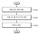
도 13은 백홀 링크 실패를 복구하는 방법을 나타내는 순서도다.Figure 13 is a sequence diagram illustrating a method for recovering a backhaul link failure.
도 13을 참조하면, RN은 백홀 링크 실패를 검출한다(S1310). 몇몇의 가능성은 백홀 링크 실패 검출의 기준으로 고려될 수 있다. 예를 들어, RN은 주어진(given) 시간 동안 어떠한 DL 제어 신호가 수신되지 않는다면 백홀 링크 실패가 발생한 것으로 간주할 수 있다. 다른 예를 들어, RN은 주어진(given) 수만큼의 스케줄링 요청을 전송한 후 주어진(given) 주기(period)의 시간 동안 해당 UL 그랜트(grant)이 수신되지 않는다면 백홀 링크 실패가 발생한 것으로 간주할 수 있다. 다른 예를 들어, RN은 주어진(given) 일련의 수만큼의 DL 데이터 패킷(예컨대, R-PDSCH)의 복호화가 실패한다면 백홀 링크 실패가 발생한 것으로 간주할 수 있다.Referring to FIG. 13, the RN detects a backhaul link failure (S1310). Several possibilities can be considered as a basis for backhaul link failure detection. For example, the RN may consider a backhaul link failure if no DL control signal is received for a given time period. In another example, the RN can consider a backhaul link failure if a corresponding UL grant is not received for a given period of time after sending a given number of scheduling requests have. For another example, the RN can consider a backhaul link failure if a decoding of a given number of DL data packets (e.g., R-PDSCH) fails.
RN은 중계 모드에서 UE 모드로 동작 모드를 변경한다(S1320). 즉, 백홀 링크 실패를 탐지한 RN이 UE 모드를 수행하도록 한다.The RN changes the operation mode from the relay mode to the UE mode (S1320). That is, the RN that detects the backhaul link failure performs the UE mode.
UE 모드에 있어서, RN은 관련 중계 UE로 어떠한 신호도 보내지 않고, BS에 직접적으로 연결되는 UE와 동일한 동작을 수행한다(예컨대, 일부 또는 모든 서브프레임에서 해당 BS로부터 DL 신호를 수신). 반 2중(half duplex) RN은 중계 모드에서 R-PDCCH를 통해 DL 제어를 수신할 수 있지만, UE 모드에서는 PDCCH를 통해 DL 제어를 수신할 수 있다.In UE mode, the RN does not send any signal to the associated relay UE, but performs the same operation as the UE directly connected to the BS (e.g., receiving DL signals from the BS in some or all subframes). A half duplex RN can receive DL control on R-PDCCH in relay mode, but can receive DL control on PDCCH in UE mode.
UE 모드로 천이(transition)되면, RN은 자신을 BS와 재연결하기 위해 초기 액세스 과정과 유사(또는 동일)한 액세스 과정을 시도한다(S1330). 예를 들어, RN은 RACH(Random Access Channel) 구성(configuration)을 획득하기 위해 BS의 BCH(Broadcast Channel)를 복호화하여, BS로 랜덤 액세스 프리앰블을 전송한다. 링크 실패를 빨리 복구하기 위해, BS는 RN의 액세스를 목적으로 하는 하나 이상의 RACH 프리앰블을 예약(reserve)할 수 있다.When transitioning to the UE mode, the RN attempts an access procedure similar to (or identical to) the initial access procedure to reconnect itself to the BS (S1330). For example, the RN decodes the BCH (Broadcast Channel) of the BS to obtain a RACH (Random Access Channel) configuration and transmits the random access preamble to the BS. To quickly recover from a link failure, the BS may reserve one or more RACH preambles for the purpose of accessing the RN.
RN은 어떤 서브프레임에서 UE 모드에 있을 수 있다. 백홀 링크 실패가 발생하면, RN은 BS와 통신하기 위해 하나 이상의 서브프레임에서 UE 모드로 천이한다. RN이 UE 모드에서 동작하는 서브프레임은 리저브드 서브프레임(reserved subframe)으로 불린다. RN이 UE 모드로의 천이 후 동작하지 않는 서브프레임은 디세이블드(disabled) 서브프레임으로 불린다.The RN may be in UE mode in some subframe. If a backhaul link failure occurs, the RN transitions to UE mode in one or more subframes to communicate with the BS. A subframe in which the RN operates in the UE mode is called a reserved subframe. A subframe in which the RN does not operate after transition to the UE mode is called a disabled subframe.
하나 이상의 리저브드 서브프레임은 하나 이상의 무선 프레임 또는 컨피거드(configured) MBSFN 서브프레임에서의 서브프레임으로부터 선택될 수 있다. 리저브드 서브프레임은 BS와 RN 사이에서 미리 정의될 수 있다. BS는 RN으로 리저브드 서브프레임을 위한 정보를 보낼 수 있다.One or more reserved subframes may be selected from one or more radio frames or a subframe in a configured MBSFN subframe. The reserved subframe can be predefined between the BS and the RN. The BS may send information for the reserved subframe to the RN.
RN은 MBSFBN 서브프레임을 사용하여 R-PDCCH를 수신하는 동안 중계 모드에서 동작한다. 백홀 링크 실패가 탐지되는 경우, RN은 UE 모드로 천이하고, 리저브드 서브프레임에서 PDCCH를 읽는다. 백홀 링크 실패를 복구하고 BS와 RN 사이의 연결을 설립하기 위한 정보는 리저브드 서브프레임에서 PDDCH를 통해 전송될 수 있다. PDCCH를 통한 정보는 데디케이티드 랜덤 액세스 프리앰블(dedicated random access preamble) 및/또는 동기화 정보를 포함할 수 있다.RN operates in the relay mode while receiving the R-PDCCH using the MBSFBN sub-frame. If a backhaul link failure is detected, the RN transitions to UE mode and reads the PDCCH in the reserved subframe. Information for recovering the backhaul link failure and establishing a connection between the BS and the RN may be transmitted on the PDDCH in the reserved subframe. The information over the PDCCH may include a dedicated random access preamble and / or synchronization information.
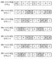
도 14는 BS 서브프레임 인덱스와 RN 서브프레임 인덱스 사이의 관계를 나타낸다.14 shows the relationship between the BS subframe index and the RN subframe index.
RN은 다른 서브프레임에서 중계 모드가 유지되는 동안 BS로부터 전송되는 BCH와 같은 중요한 제어 신호를 수신하기 위해 서빙 셀에서의 서브프레임 #0 과 #5와 같은 서브프레임에서 동작한다.RN operates in subframes such as
서브프레임 번호(number)가 RN 셀에서의 TDD에서 #0, #1, #5, 또는 #6인 서브프레임 및 FDD에서 #0, #4, #5, 또는 #9인 서브프레임에서는 RN이 백홀 신호를 수신할 수 없으므로, BS 셀의 서브프레임 #0 및 #5가 RN이 백홀 신호를 수신할 수 없는 RN 셀의 서브프레임과 일치하지 않도록 BS 셀과 RN 셀 사이의 서브프레임 오프셋을 가지는 것이 가능하다(As a RN cannot receive the backhaul signal in subframes whose subframe numbers are #0, #4, #5, or #9 in FDD and #0, #1, #5, or #6 in TDD in the RN cell, it is possible to have some subframe offset between the BS cell and the RN cell such that BS cell’s subframes #0 and #5 do not coincide with RN cell’s subframes where the RN cannot receive the backhaul signal.). 도 14는 FDD에서의 이러한 서브프레임 오프셋의 예를 나타낸다. BS는 상위 계층 시그널링(signaling)을 통해 각각의 RN의 서브프레임 인덱스를 설정(configure)하는 것이 가능하다.In a subframe in which the subframe number is # 0, # 1, # 5, or # 6 in the TDD in the RN cell and in the
BS의 서브프레임 #0 및 #5가 특정 RN으로의 백홀 링크를 위해 설정(configured)되지 않으면, RN은 이러한 두 개의 서브프레임이 MBSFN 서브프레임이 되도록 해당 MBSFN 서브프레임 구성(configuration)을 변경할 수 있다. 서브프레임 #0 및 #5는 리저브드 서브프레임이 된다.If the
중계 UE 측정 성능에 영향을 끼치지 않는 것이 유리하다. 그러나, 이러한 영향이 받아들일 수 있는 정도라면, 신속하고 간단한 실패 복구를 위해, RN은 해당 MBSFN 구성(configuration)을 변경하지 않고 상기 두 개의 서브프레임에서 백홀 신호를 수신할 수 있다. RN이 BCH를 수신하면, 예컨대, 적절한 랜덤 액세스 프리앰블을 보내는 것에 의해 BS로의 리-액세스(re-access)를 시도할 수 있다.It is advantageous not to affect the relay UE measurement performance. However, if this effect is acceptable, for fast and simple failure recovery, the RN can receive the backhaul signal in the two subframes without changing the MBSFN configuration. When the RN receives the BCH, it can try re-access to the BS, for example, by sending an appropriate random access preamble.
백홀 서브프레임이 CRS를 포함하는 경우, 즉 백홀 신호가 CRS를 가지지 않고 DM RS에 의해 복조화되는 경우에 특히 효과적인 방법이다. 현재의 Rel-8/9 LTE 스페시피케이션(specification)은 주어진(given) 수만큼의 연속적인 오류가 탐지되면 BS와 UE가 천이하는 폴백(fallback) 모드를 정의한다. 이러한 폴백 모드에서는 가장 믿을 수 있는 송신/수신 방법(예컨대, 공간 주파수 블록 코드를 통한 전송 다이버시티)이 사용된다. 그러나, RN이 백홀 링크에 기반하여 DM RS에서 동작하고 있다면, CRS가 백홀 서브프레임에 존재하지 않으므로 기존의 폴백 모드는 지원될 수 없다.This is particularly effective when the backhaul subframe includes CRS, i.e., when the backhaul signal is demodulated by the DM RS without CRS. The current Rel-8/9 LTE specification defines a fallback mode in which the BS and UE transition when a given number of consecutive errors are detected. In this fallback mode, the most reliable transmit / receive method (e.g., transmit diversity via space frequency block code) is used. However, if the RN is operating in the DM RS based on the backhaul link, the existing fallback mode can not be supported since the CRS is not present in the backhaul subframe.
RN은 백업(backup) 서브프레임으로 하나 이상의 서브프레임을 사용할 수 있다. 이러한 백업 서브프레임은 CRS를 포함하는 것이 바람직하다. 이러한 백업 서브프레임은 백홀 서브프레임으로 사용되지 않는다; 즉, RN은 백홀 신호를 수신하지 않고 일반적인 중계 동작에서의 이러한 백업 서브프레임에서 해당 액세스 링크 신호를 전송한다. RN이 링크 실패를 탐지하면, RN은 백홀 링크 실패를 복구하기 전에 폴백 모드를 통해 이러한 백업 서브프레임에서 DL 제어 신호를 수신하는 것을 시도한다. BS가 RN으로부터 어떠한 응답(response)도 수신하지 않는다면, BS는 이러한 백업 서브프레임에서 적절한 DL 제어 신호를 전송한다. BS는 상위 계층 시그널링을 통해 RN으로 백업 서브프레임 인덱스를 보낼 수 있다. RN이 이러한 백업 서브프레임에서 BS로부터 해당 DL 제어 신호를 수신하지 않는다면, 일부 또는 모든 프레임에서 UE 모드로 천이할 수 있다.The RN may use one or more subframes as a backup subframe. Such a backup sub-frame preferably includes a CRS. This backup subframe is not used as a backhaul subframe; That is, the RN does not receive the backhaul signal and transmits the corresponding access link signal in this backup sub-frame in a general relay operation. If the RN detects link failure, the RN attempts to receive a DL control signal in this backup sub-frame via the fallback mode before recovering the backhaul link failure. If the BS does not receive any response from the RN, the BS transmits an appropriate DL control signal in this backup sub-frame. The BS may send the backup subframe index to the RN through higher layer signaling. If the RN does not receive the corresponding DL control signal from the BS in this backup sub-frame, it may transition to UE mode in some or all of the frames.
도 15는 BS와 RN을 나타내는 블록도이다.15 is a block diagram showing a BS and an RN.
BS(100)는 프로세서(processor, 110), 메모리(memory, 120) 및 RF부(RF(radio frequency) unit, 130)를 포함한다. 프로세서(110)는 제안된 기능, 과정 및/또는 방법을 구현한다. 메모리(120)는 프로세서(110)와 연결되어, 프로세서(110)를 구동하기 위한 다양한 정보를 저장한다. RF부(130)는 프로세서(110)와 연결되어, 무선 신호를 전송 및/또는 수신한다.The
RN(200)은 프로세서(210), 메모리(220) 및 RF부(230)를 포함한다. 프로세서(210)은 제안된 기능, 과정 및/또는 방법을 구현한다. 즉, 프로세서(210)은 백홀 링크 실패를 탐지하고, 중계 모드에서 RN이 UE의 BS에 직접적으로 연결된 UE와 동일한 동작을 수행하는 UE 모드로 동작 모드를 변경하고, 재연결(re-connect)을 위해 RN의 BS로의 액세스를 수행한다. 메모리(220)는 프로세서(210)와 연결되어, 프로세서(210)를 구동하기 위한 다양한 정보를 저장한다. RF부(230)는 프로세서(210)와 연결되어, 무선 신호를 전송 및/또는 수신한다.The
프로세서(110, 210)는 ASIC(application-specific integrated circuit), 다른 칩셋, 논리 회로, 데이터 처리 장치 및/또는 베이스밴드 신호 및 무선 신호를 상호 변환하는 변환기를 포함할 수 있다. 메모리(120, 220)는 ROM(read-only memory), RAM(random access memory), 플래쉬 메모리, 메모리 카드, 저장 매체 및/또는 다른 저장 장치를 포함할 수 있다. RF부(130, 230)는 무선 신호를 전송 및/또는 수신하는 하나 이상의 안테나를 포함할 수 있다. 실시예가 소프트웨어로 구현될 때, 상술한 기법은 상술한 기능을 수행하는 모듈(과정, 기능 등)로 구현될 수 있다. 모듈은 메모리(120, 220)에 저장되고, 프로세서(110, 210)에 의해 실행될 수 있다. 메모리(120, 220)는 프로세서(110, 210) 내부 또는 외부에 있을 수 있고, 잘 알려진 다양한 수단으로 프로세서(110, 210)와 연결될 수 있다.
본 발명은 실시예로서 실제적으로 고려되는 것과 관련되어 설명되었지만, 본 발명이 상술한 실시예에 한정되지 않는 것으로 이해되어야 하며, 이하의 특허청구범위의 범위와 사상 내에 포함된 동등한 변경 및 다양한 수정을 포함하는 것으로 해석되어야 한다.
While the invention has been described in connection with what is presently considered to be the preferred embodiment, it is to be understood that the invention is not limited to the disclosed embodiments, but, on the contrary, is intended to cover various modifications and equivalent arrangements included within the spirit and scope of the appended claims. Should be construed as including.
Claims (12)
Translated fromKorean중계 노드에 의해 기지국으로부터, 상기 기지국과 상기 중계 노드 사이의 중계 신호를 위해 사용되는 복수의 중계 서브프레임에 관한 정보를 수신하는 단계;
중계 노드에 의해, 상기 복수의 중계 서브프레임을 이용하여 상기 신호의 중계를 시도하는 동안 백홀 링크 실패를 검출하는 단계;
상기 백홀 링크 실패가 검출되는 경우, 상기 중계 노드에 의해 상기 복수의 중계 서브프레임이 동작하지 않게(disable) 하고, 상기 복수의 중계 서브프레임에 해당하지 않는 서브프레임 중에서 적어도 하나의 서브프레임을 결정하는 단계; 및
중계 노드에 의해 상기 기지국으로부터, 상기 적어도 하나의 결정된 서브프레임에서 상기 백홀 링크 실패를 복구하기 위한 정보를 수신하는 단계를 포함하는 것을 특징으로 하는 방법.
A method for recovering a backhaul link failure between a base station (BS) and a relay node (RN)
Receiving information on a plurality of relay subframes used by the relay node from the base station for relay signals between the base station and the relay node;
Detecting, by the relay node, a backhaul link failure while attempting to relay the signal using the plurality of relay subframes;
Wherein when the failure of the backhaul link is detected, the relay node disables the plurality of relay subframes and determines at least one subframe among subframes not corresponding to the plurality of relay subframes step; And
Receiving information from the base station by the relay node to recover the backhaul link failure in the at least one determined subframe.
상기 중계 노드에 의해 상기 기지국으로부터, 상기 적어도 하나의 결정된 서브프레임에 관한 정보를 수신하는 단계를 더 포함하는 것을 특징으로 하는 방법.
The method according to claim 1,
Further comprising receiving, by the relay node, information about the at least one determined sub-frame from the base station.
상기 적어도 하나의 결정된 서브프레임은 미리 정의되는 것을 특징으로 하는 방법.
The method according to claim 1,
Wherein the at least one determined subframe is predefined.
상기 적어도 하나의 결정된 서브프레임은 무선 프레임의 첫 번째 및 여섯 번째 서브프레임을 포함하는 것을 특징으로 하는 방법.
The method of claim 3,
Wherein the at least one determined subframe comprises a first and a sixth subframe of a radio frame.
상기 백홀 링크 실패를 복구하기 위한 상기 정보는 랜덤 액세스 프리앰블(random access preamble)에 관한 정보를 포함하는 것을 특징으로 하는 방법.
The method according to claim 1,
Wherein the information for recovering the backhaul link failure includes information about a random access preamble.
상기 백홀 링크 실패는
상기 중계 노드가 소정 기간 동안 상기 기지국으로부터 하향링크(Downlink: DL) 제어 신호를 수신하지 않는 경우,
상기 중계 노드가 소정 기간 내에서 상기 기지국으로부터 상향링크(Uplink: UL) 그랜트(grant)를 수신하지 않는 경우, 또는
상기 중계 노드가 소정의 수의 하향링크 데이터 패킷들을 복호화하는 것에 실패하는 경우에 검출되는 것을 특징으로 하는 방법.
The method according to claim 1,
The backhaul link failure
If the relay node does not receive a downlink (DL) control signal from the base station for a predetermined period of time,
When the relay node does not receive an uplink (UL) grant from the base station within a predetermined period, or
Characterized in that it is detected when the relay node fails to decode a predetermined number of downlink data packets.
무선 신호를 송신 및 수신하는 RF(Radio Frequency)부; 및
상기 RF부에 연결되는 프로세서를 포함하되, 상기 프로세서는
기지국으로부터, 중계 신호를 위해 사용되는 복수의 중계 서브프레임에 관한 정보를 수신하고;
상기 복수의 중계 서브프레임을 이용하여 상기 신호의 중계를 시도하는 동안 백홀 링크 실패를 검출하고;
상기 백홀 링크 실패가 검출되는 경우, 상기 복수의 중계 서브프레임이 동작하지 않게(disable) 하고, 상기 복수의 중계 서브프레임에 해당하지 않는 서브프레임 중에서 적어도 하나의 서브프레임을 결정하고; 및
상기 기지국으로부터, 상기 적어도 하나의 결정된 서브프레임에서 상기 백홀 링크 실패를 복구하기 위한 정보를 수신하는 것을 특징으로 하는 장치.
An apparatus for restoring a backhaul link failure with a base station (BS), comprising:
A radio frequency (RF) unit for transmitting and receiving a radio signal; And
And a processor coupled to the RF unit,
Receiving, from a base station, information about a plurality of relay subframes used for relay signals;
Detecting a backhaul link failure while attempting to relay the signal using the plurality of relay subframes;
Determining at least one subframe among the subframes not corresponding to the plurality of relay subframes when the backhaul link failure is detected, disabling the plurality of relay subframes; And
From the base station, information for recovering the backhaul link failure in the at least one determined subframe.
상기 프로세서는 상기 기지국으로부터, 상기 적어도 하나의 결정된 서브프레임에 관한 정보를 수신하는 것을 특징으로 하는 장치.
8. The method of claim 7,
Wherein the processor receives, from the base station, information regarding the at least one determined sub-frame.
상기 적어도 하나의 결정된 서브프레임은 미리 정의되는 것을 특징으로 하는 장치.
8. The method of claim 7,
Wherein the at least one determined subframe is predefined.
상기 적어도 하나의 결정된 서브프레임은 무선 프레임의 첫 번째 및 여섯 번째 서브프레임을 포함하는 것을 포함하는 것을 특징으로 하는 장치.
10. The method of claim 9,
Wherein the at least one determined subframe comprises a first and a sixth subframe of a radio frame.
상기 백홀 링크 실패를 복구하기 위한 상기 정보는 랜덤 액세스 프리앰블(random access preamble)에 관한 정보를 포함하는 것을 특징으로 하는 장치.
8. The method of claim 7,
Wherein the information for recovering the backhaul link failure includes information about a random access preamble.
상기 백홀 링크 실패는
중계 노드가 소정 기간 동안 상기 기지국으로부터 하향링크(Downlink: DL) 제어 신호를 수신하지 않는 경우,
중계 노드가 소정 기간 내에서 상기 기지국으로부터 상향링크(Uplink: UL) 그랜트(grant)를 수신하지 않는 경우, 또는
중계 노드가 소정의 수의 하향링크 데이터 패킷들을 복호화하는 것에 실패하는 경우에 검출되는 것을 특징으로 하는 장치.
8. The method of claim 7,
The backhaul link failure
If the relay node does not receive a downlink (DL) control signal from the base station for a predetermined period,
When the relay node does not receive an uplink (UL) grant from the base station within a predetermined period, or
And when the relay node fails to decode a predetermined number of downlink data packets.
Applications Claiming Priority (3)
| Application Number | Priority Date | Filing Date | Title |
|---|---|---|---|
| US30367010P | 2010-02-11 | 2010-02-11 | |
| US61/303,670 | 2010-02-11 | ||
| PCT/KR2011/000922WO2011099802A2 (en) | 2010-02-11 | 2011-02-11 | Method and apparatus of recovering backhaul link failure between base station and relay node |
Publications (2)
| Publication Number | Publication Date |
|---|---|
| KR20130007551A KR20130007551A (en) | 2013-01-18 |
| KR101759366B1true KR101759366B1 (en) | 2017-07-31 |
Family
ID=44368321
Family Applications (1)
| Application Number | Title | Priority Date | Filing Date |
|---|---|---|---|
| KR1020127020909AActiveKR101759366B1 (en) | 2010-02-11 | 2011-02-11 | Method and apparatus of recovering backhaul link failure between base station and relay node |
Country Status (4)
| Country | Link |
|---|---|
| US (1) | US8861332B2 (en) |
| EP (1) | EP2534777B1 (en) |
| KR (1) | KR101759366B1 (en) |
| WO (1) | WO2011099802A2 (en) |
Families Citing this family (48)
| Publication number | Priority date | Publication date | Assignee | Title |
|---|---|---|---|---|
| US10425134B2 (en) | 2004-04-02 | 2019-09-24 | Rearden, Llc | System and methods for planned evolution and obsolescence of multiuser spectrum |
| US10277290B2 (en) | 2004-04-02 | 2019-04-30 | Rearden, Llc | Systems and methods to exploit areas of coherence in wireless systems |
| US9312929B2 (en) | 2004-04-02 | 2016-04-12 | Rearden, Llc | System and methods to compensate for Doppler effects in multi-user (MU) multiple antenna systems (MAS) |
| US8654815B1 (en) | 2004-04-02 | 2014-02-18 | Rearden, Llc | System and method for distributed antenna wireless communications |
| US8542763B2 (en) | 2004-04-02 | 2013-09-24 | Rearden, Llc | Systems and methods to coordinate transmissions in distributed wireless systems via user clustering |
| US11451275B2 (en) | 2004-04-02 | 2022-09-20 | Rearden, Llc | System and method for distributed antenna wireless communications |
| US11394436B2 (en) | 2004-04-02 | 2022-07-19 | Rearden, Llc | System and method for distributed antenna wireless communications |
| US10985811B2 (en) | 2004-04-02 | 2021-04-20 | Rearden, Llc | System and method for distributed antenna wireless communications |
| US9826537B2 (en) | 2004-04-02 | 2017-11-21 | Rearden, Llc | System and method for managing inter-cluster handoff of clients which traverse multiple DIDO clusters |
| US11309943B2 (en) | 2004-04-02 | 2022-04-19 | Rearden, Llc | System and methods for planned evolution and obsolescence of multiuser spectrum |
| US10886979B2 (en) | 2004-04-02 | 2021-01-05 | Rearden, Llc | System and method for link adaptation in DIDO multicarrier systems |
| US10200094B2 (en) | 2004-04-02 | 2019-02-05 | Rearden, Llc | Interference management, handoff, power control and link adaptation in distributed-input distributed-output (DIDO) communication systems |
| US10749582B2 (en) | 2004-04-02 | 2020-08-18 | Rearden, Llc | Systems and methods to coordinate transmissions in distributed wireless systems via user clustering |
| US9685997B2 (en) | 2007-08-20 | 2017-06-20 | Rearden, Llc | Systems and methods to enhance spatial diversity in distributed-input distributed-output wireless systems |
| RU2598816C2 (en) | 2010-08-03 | 2016-09-27 | Нек Корпорейшн | Retransmission station device, mobile communication system, base station device and method of controlling relay station |
| KR20120024355A (en)* | 2010-08-11 | 2012-03-14 | 엘지에릭슨 주식회사 | Method for resource element group downsizing of r-pdcch and mobile telecommunication system for the same |
| US20120224472A1 (en)* | 2011-03-04 | 2012-09-06 | Electronics And Telecommunications Research Institute | Method for relaying of base station, method for relaying of terminal and method for transmitting |
| US8792924B2 (en)* | 2011-05-06 | 2014-07-29 | Futurewei Technologies, Inc. | System and method for multi-cell access |
| US11696300B2 (en) | 2011-10-29 | 2023-07-04 | Comcast Cable Communications, Llc | Configuration of reduced transmission power time intervals based on traffic load |
| US8873467B2 (en)* | 2011-12-05 | 2014-10-28 | Ofinno Technologies, Llc | Control channel detection |
| US8971275B2 (en) | 2011-12-31 | 2015-03-03 | Ofinno Technologies, Llc | Almost blank subframe indication in wireless networks |
| GB2498750A (en)* | 2012-01-26 | 2013-07-31 | Sharp Kk | Control channel design for relay node backhaul |
| MX354045B (en)* | 2012-05-04 | 2018-02-09 | Rearden Llc | System and methods for coping with doppler effects in distributed-input distributed-output wireless systems. |
| US11189917B2 (en) | 2014-04-16 | 2021-11-30 | Rearden, Llc | Systems and methods for distributing radioheads |
| US10194346B2 (en) | 2012-11-26 | 2019-01-29 | Rearden, Llc | Systems and methods for exploiting inter-cell multiplexing gain in wireless cellular systems via distributed input distributed output technology |
| US11190947B2 (en) | 2014-04-16 | 2021-11-30 | Rearden, Llc | Systems and methods for concurrent spectrum usage within actively used spectrum |
| US11050468B2 (en) | 2014-04-16 | 2021-06-29 | Rearden, Llc | Systems and methods for mitigating interference within actively used spectrum |
| US9078157B2 (en)* | 2012-12-31 | 2015-07-07 | Verizon Patent And Licensing Inc. | Quick recovery of RF sessions after backhaul link failure |
| KR20140088375A (en)* | 2013-01-02 | 2014-07-10 | 삼성전자주식회사 | Apparatus and method for recovering wireless link between base stations in wireless communication system |
| KR101799475B1 (en)* | 2013-03-11 | 2017-11-20 | 후아웨이 테크놀러지 컴퍼니 리미티드 | Method and apparatus for data transmission |
| US10164698B2 (en) | 2013-03-12 | 2018-12-25 | Rearden, Llc | Systems and methods for exploiting inter-cell multiplexing gain in wireless cellular systems via distributed input distributed output technology |
| US9973246B2 (en) | 2013-03-12 | 2018-05-15 | Rearden, Llc | Systems and methods for exploiting inter-cell multiplexing gain in wireless cellular systems via distributed input distributed output technology |
| US9923657B2 (en) | 2013-03-12 | 2018-03-20 | Rearden, Llc | Systems and methods for exploiting inter-cell multiplexing gain in wireless cellular systems via distributed input distributed output technology |
| US10488535B2 (en) | 2013-03-12 | 2019-11-26 | Rearden, Llc | Apparatus and method for capturing still images and video using diffraction coded imaging techniques |
| RU2767777C2 (en) | 2013-03-15 | 2022-03-21 | Риарден, Ллк | Systems and methods of radio frequency calibration using the principle of reciprocity of channels in wireless communication with distributed input - distributed output |
| US10448351B2 (en) | 2013-04-02 | 2019-10-15 | Qualcomm Incorporated | Employing neighboring cell assistance information for interference mitigation |
| JP2015177497A (en)* | 2014-03-18 | 2015-10-05 | 日本電気株式会社 | Point-to-point radio device, mobile backhaul system, communication control method and program |
| US11290162B2 (en) | 2014-04-16 | 2022-03-29 | Rearden, Llc | Systems and methods for mitigating interference within actively used spectrum |
| US9986458B2 (en)* | 2015-08-27 | 2018-05-29 | Qualcomm Incorporated | Mitigating constrained backhaul availability between a radio access network (RAN) and core network |
| CN109803296B (en)* | 2017-11-17 | 2021-05-14 | 华为技术有限公司 | Method and device for signal transmission |
| US10945185B2 (en)* | 2018-07-11 | 2021-03-09 | Lg Electronics Inc. | Method and apparatus for supporting fast link recovery and link status reporting in wireless communication system |
| US12096503B2 (en) | 2018-08-03 | 2024-09-17 | Lenovo (Beijing) Limited | Method and apparatus for handling radio link failure |
| US11696204B2 (en) | 2018-08-07 | 2023-07-04 | Lg Electronics Inc. | Operating method of node in wireless communication system, and device using method |
| US11638319B2 (en)* | 2019-02-12 | 2023-04-25 | Samsung Electronics Co., Ltd. | Handling radio link failure in cellular mesh networks |
| US12193094B2 (en)* | 2019-02-14 | 2025-01-07 | Lg Electronics Inc. | Method and apparatus for failure notification on backhaul link in wireless communication system |
| US11360743B2 (en)* | 2019-07-21 | 2022-06-14 | Cyber Reliant Corp. | Data set including a secure key |
| KR102591141B1 (en)* | 2019-11-05 | 2023-10-18 | 한국전자통신연구원 | Method and device for transmitting and receiving reference signals |
| KR102589831B1 (en) | 2022-12-27 | 2023-10-16 | 한화시스템 주식회사 | Method of controlling access to backhaul link in in-band backhaul base station |
Citations (2)
| Publication number | Priority date | Publication date | Assignee | Title |
|---|---|---|---|---|
| US20080219268A1 (en) | 2007-03-01 | 2008-09-11 | Dennison Larry R | Software control plane for switches and routers |
| US20090257353A1 (en) | 2008-03-18 | 2009-10-15 | Qualcomm, Incorporated | Method of network management by assistance from terminal using control-plane signaling between terminal and network |
Family Cites Families (5)
| Publication number | Priority date | Publication date | Assignee | Title |
|---|---|---|---|---|
| US8385977B2 (en)* | 2001-05-02 | 2013-02-26 | Trex Enterprises Corp | Cellular communication system with high speed content distribution |
| US9867203B2 (en) | 2008-07-11 | 2018-01-09 | Qualcomm Incorporated | Synchronous TDM-based communication in dominant interference scenarios |
| US8818381B2 (en)* | 2009-08-07 | 2014-08-26 | Nokia Siemens Networks Oy | Operation in case of radio link failure |
| US9609688B2 (en)* | 2010-04-05 | 2017-03-28 | Qualcomm Incorporated | Methods and apparatus to facilitate relay startup and radio link failure (RLF) handling |
| EP2387270A1 (en)* | 2010-05-12 | 2011-11-16 | Nokia Siemens Networks Oy | Radio link failure recovery control in communication network having relay nodes |
- 2011
- 2011-02-11USUS13/578,588patent/US8861332B2/enactiveActive
- 2011-02-11KRKR1020127020909Apatent/KR101759366B1/enactiveActive
- 2011-02-11EPEP11742494.5Apatent/EP2534777B1/enactiveActive
- 2011-02-11WOPCT/KR2011/000922patent/WO2011099802A2/enactiveApplication Filing
Patent Citations (2)
| Publication number | Priority date | Publication date | Assignee | Title |
|---|---|---|---|---|
| US20080219268A1 (en) | 2007-03-01 | 2008-09-11 | Dennison Larry R | Software control plane for switches and routers |
| US20090257353A1 (en) | 2008-03-18 | 2009-10-15 | Qualcomm, Incorporated | Method of network management by assistance from terminal using control-plane signaling between terminal and network |
Non-Patent Citations (2)
| Title |
|---|
| 3GPP R2-100176* |
| 3GPP R2-100256* |
Also Published As
| Publication number | Publication date |
|---|---|
| EP2534777A4 (en) | 2017-06-28 |
| KR20130007551A (en) | 2013-01-18 |
| WO2011099802A2 (en) | 2011-08-18 |
| US20120314567A1 (en) | 2012-12-13 |
| WO2011099802A3 (en) | 2012-01-05 |
| EP2534777A2 (en) | 2012-12-19 |
| EP2534777B1 (en) | 2019-01-02 |
| US8861332B2 (en) | 2014-10-14 |
Similar Documents
| Publication | Publication Date | Title |
|---|---|---|
| KR101759366B1 (en) | Method and apparatus of recovering backhaul link failure between base station and relay node | |
| US10652001B2 (en) | Method and apparatus for reducing inter-cell interference in radio communication system | |
| US10306619B2 (en) | Method and apparatus for channel estimation for radio link between a base station and a relay station | |
| US9888404B2 (en) | Method and device for aperiodically reporting channel state information in wireless connection system | |
| CN102668409B (en) | Backhaul downlink signal decoding method of relay station and relay station using the method | |
| US9504027B2 (en) | Method and apparatus for transmitting a control channel and a data channel in a wireless communication system | |
| KR101789630B1 (en) | Method for transmitting and receiving signal of relay in radio communication system supporting multiple carriers | |
| JP5281200B2 (en) | Method of using reference signal of relay station and relay station using the method | |
| KR101962140B1 (en) | Method and apparatus for transceiving a downlink control channel in a wireless communication system | |
| US20120320819A1 (en) | Relay node apparatus for transmitting and receiving signal according to link operation mode in wireless communication system and method thereof | |
| US20120076071A1 (en) | Method and apparatus for transmitting/receiving a signal in a wireless communication system | |
| KR20100131951A (en) | Method and apparatus for transmitting / receiving signal in wireless communication system |
Legal Events
| Date | Code | Title | Description |
|---|---|---|---|
| PA0105 | International application | Patent event date:20120809 Patent event code:PA01051R01D Comment text:International Patent Application | |
| PG1501 | Laying open of application | ||
| A201 | Request for examination | ||
| PA0201 | Request for examination | Patent event code:PA02012R01D Patent event date:20160203 Comment text:Request for Examination of Application | |
| E902 | Notification of reason for refusal | ||
| PE0902 | Notice of grounds for rejection | Comment text:Notification of reason for refusal Patent event date:20161124 Patent event code:PE09021S01D | |
| E701 | Decision to grant or registration of patent right | ||
| PE0701 | Decision of registration | Patent event code:PE07011S01D Comment text:Decision to Grant Registration Patent event date:20170511 | |
| GRNT | Written decision to grant | ||
| PR0701 | Registration of establishment | Comment text:Registration of Establishment Patent event date:20170712 Patent event code:PR07011E01D | |
| PR1002 | Payment of registration fee | Payment date:20170712 End annual number:3 Start annual number:1 | |
| PG1601 | Publication of registration | ||
| PR1001 | Payment of annual fee | Payment date:20210609 Start annual number:5 End annual number:5 | |
| PR1001 | Payment of annual fee | Payment date:20250610 Start annual number:9 End annual number:9 |