KR101757065B1 - Battery charger for vehicle using flexible piezoelectric element in tire - Google Patents
Battery charger for vehicle using flexible piezoelectric element in tireDownload PDFInfo
- Publication number
- KR101757065B1 KR101757065B1KR1020150159369AKR20150159369AKR101757065B1KR 101757065 B1KR101757065 B1KR 101757065B1KR 1020150159369 AKR1020150159369 AKR 1020150159369AKR 20150159369 AKR20150159369 AKR 20150159369AKR 101757065 B1KR101757065 B1KR 101757065B1
- Authority
- KR
- South Korea
- Prior art keywords
- tire
- wall
- piezoelectric element
- flexible piezoelectric
- contact
- Prior art date
- Legal status (The legal status is an assumption and is not a legal conclusion. Google has not performed a legal analysis and makes no representation as to the accuracy of the status listed.)
- Expired - Fee Related
Links
Images


Classifications
- H—ELECTRICITY
- H02—GENERATION; CONVERSION OR DISTRIBUTION OF ELECTRIC POWER
- H02N—ELECTRIC MACHINES NOT OTHERWISE PROVIDED FOR
- H02N2/00—Electric machines in general using piezoelectric effect, electrostriction or magnetostriction
- H02N2/18—Electric machines in general using piezoelectric effect, electrostriction or magnetostriction producing electrical output from mechanical input, e.g. generators
- H—ELECTRICITY
- H02—GENERATION; CONVERSION OR DISTRIBUTION OF ELECTRIC POWER
- H02N—ELECTRIC MACHINES NOT OTHERWISE PROVIDED FOR
- H02N11/00—Generators or motors not provided for elsewhere; Alleged perpetua mobilia obtained by electric or magnetic means
- H02N11/002—Generators
- B—PERFORMING OPERATIONS; TRANSPORTING
- B60—VEHICLES IN GENERAL
- B60C—VEHICLE TYRES; TYRE INFLATION; TYRE CHANGING; CONNECTING VALVES TO INFLATABLE ELASTIC BODIES IN GENERAL; DEVICES OR ARRANGEMENTS RELATED TO TYRES
- B60C19/00—Tyre parts or constructions not otherwise provided for
- B—PERFORMING OPERATIONS; TRANSPORTING
- B60—VEHICLES IN GENERAL
- B60C—VEHICLE TYRES; TYRE INFLATION; TYRE CHANGING; CONNECTING VALVES TO INFLATABLE ELASTIC BODIES IN GENERAL; DEVICES OR ARRANGEMENTS RELATED TO TYRES
- B60C23/00—Devices for measuring, signalling, controlling, or distributing tyre pressure or temperature, specially adapted for mounting on vehicles; Arrangement of tyre inflating devices on vehicles, e.g. of pumps or of tanks; Tyre cooling arrangements
- B60C23/02—Signalling devices actuated by tyre pressure
- B60C23/04—Signalling devices actuated by tyre pressure mounted on the wheel or tyre
- B60C23/0408—Signalling devices actuated by tyre pressure mounted on the wheel or tyre transmitting the signals by non-mechanical means from the wheel or tyre to a vehicle body mounted receiver
- B60C23/041—Means for supplying power to the signal- transmitting means on the wheel
- B60C23/0411—Piezoelectric generators
- H01L41/053—
- B—PERFORMING OPERATIONS; TRANSPORTING
- B60—VEHICLES IN GENERAL
- B60C—VEHICLE TYRES; TYRE INFLATION; TYRE CHANGING; CONNECTING VALVES TO INFLATABLE ELASTIC BODIES IN GENERAL; DEVICES OR ARRANGEMENTS RELATED TO TYRES
- B60C5/00—Inflatable pneumatic tyres or inner tubes
- B60C5/12—Inflatable pneumatic tyres or inner tubes without separate inflatable inserts, e.g. tubeless tyres with transverse section open to the rim
- Y—GENERAL TAGGING OF NEW TECHNOLOGICAL DEVELOPMENTS; GENERAL TAGGING OF CROSS-SECTIONAL TECHNOLOGIES SPANNING OVER SEVERAL SECTIONS OF THE IPC; TECHNICAL SUBJECTS COVERED BY FORMER USPC CROSS-REFERENCE ART COLLECTIONS [XRACs] AND DIGESTS
- Y10—TECHNICAL SUBJECTS COVERED BY FORMER USPC
- Y10S—TECHNICAL SUBJECTS COVERED BY FORMER USPC CROSS-REFERENCE ART COLLECTIONS [XRACs] AND DIGESTS
- Y10S74/00—Machine element or mechanism
- Y10S74/09—Perpetual motion gimmicks
Landscapes
- Engineering & Computer Science (AREA)
- Mechanical Engineering (AREA)
- General Electrical Machinery Utilizing Piezoelectricity, Electrostriction Or Magnetostriction (AREA)
Abstract
Translated fromKorean
Description
Translated fromKorean본 발명은 압전소자를 이용한 차량의 보조 발전 장치에 관한 것으로써, 구체적으로 휘어짐이 가능한 플렉서블 압전소자를 이용하여 차량의 타이어 내부의 압력 전달에 따른 지속적인 발전이 가능하도록 한 플랙서블 압전소자를 이용한 자동차 타이어 적용 발전 장치에 관한 것이다.BACKGROUND OF THE INVENTION 1. Field of the Invention The present invention relates to an auxiliary power generation apparatus for a vehicle using a piezoelectric element, and more particularly, to a vehicle auxiliary power generation apparatus using a flexible piezoelectric element capable of flexing, To a tire-mounted power generation device.
차량에는 차량 내 다양한 부품의 동작을 위한 전기를 공급하여 줄 수 있도록 배터리가 구비된다.The vehicle is provided with a battery so as to supply electricity for operation of various parts in the vehicle.
이러한 배터리는 축전지 형태로서, 차량 내 부품들로 전기를 공급하는 한편, 차량 주행 시 바퀴의 회전 운동에 의하여 구동되는 발전기(generator)에 의하여 충전 또한 이루어지도록 되어 있는 것이 일반적이다.Such a battery is generally in the form of a battery, and it is general that charging is also performed by a generator driven by the rotational motion of the wheel while driving the vehicle while supplying electricity to components in the vehicle.
그런데, 기술의 발전에 따라 차량에서 사용되는 전기적 부품들이 점점 늘어나게 되어, 차량 운행에 있어 전기의 소모가 늘어나고 있는 추세이다.However, with the development of technology, the number of electric parts used in the vehicle is increasing more and more, and the consumption of electricity is increasing in the vehicle operation.
이러한 문제를 극복하기 위해서는 가장 단순하게는 배터리의 용량을 늘리는 방법을 생각할 수 있다.To overcome this problem, the simplest way to think about how to increase the capacity of the battery.
그러나 연비 문제 등을 고려하여 차량 내 부품이 갈수록 소형화 및 경량화 되는 추세에 있으며, 따라서 배터리의 용량을 늘리는 방법은 이러한 추세에 역행할 뿐 아니라 용량 확대에 제한이 있다.However, in consideration of the fuel efficiency problem, parts in the vehicle are becoming smaller and lighter in size, and accordingly, the method of increasing the capacity of the battery is contrary to this tendency and there is a limitation in the capacity expansion.
이에 따라 배터리 전력 부족 문제를 해결하기 위하여 한편으로는 차량 내 전기적 부품들의 전력 소비를 절감하기 위한 다양한 연구가 이루어져 오고 있으며, 다른 한편으로는 배터리의 충전량을 보다 늘릴 수 있는 방안이 연구되고 있다.Accordingly, in order to solve the battery power shortage problem, various researches have been made to reduce power consumption of electrical parts in the vehicle on the one hand, and on the other hand, a method of further increasing the charged amount of the battery has been studied.
한국실용신안공개 제1998-0028334호("압전소자를 이용한 배터리 충전 장치", 1998.08.05), 한국특허공개 제2003-0039692호("차량 현가 장치를 이용한 보조 발전기", 2003.05.22), 일본특허공개 제2011-041344호("발전장치", 2011.02.24) 등에서는, 발전기에 의한 충전에 더불어 배터리를 보조로 더 충전할 수 있도록 하는 여러기술들이 개시되어 있다.Korean Utility Model Laid Open Publication No. 1998-0028334 ("Battery Charging Device Using Piezoelectric Device", Aug. 08, 1998), Korean Patent Publication No. 2003-0039692 ("Auxiliary Power Generator with Vehicle Suspension", 2003.05.22) Japanese Patent Application Laid-Open No. 2011-041344 ("Power Generation Device", Feb. 24, 2011) discloses various techniques for charging a battery with auxiliary power in addition to charging by a generator.
상기 기술들은 모두 차량의 현가장치(suspension system)에 구비된 압전소자(piezoelectric element)를 이용하여 보조 충전이 이루어질 수 있도록 한 것이다.All of the above techniques are such that auxiliary charging can be performed using a piezoelectric element provided in a suspension system of a vehicle.
이러한 현가장치란 스프링 작용에 의하여 차체의 중량을 지지함과 동시에 차륜의 상하 진동을 완화하는 장치를 말하는데, 즉 차량 주행 시 상하 방향으로의 압력 변화가 수시로 일어나는 장치로서, 이러한 현가장치에 압전소자를 구비함으로써 상당한 보조 충전 효과를 기대할 수 있다.Such a suspension device is a device for supporting the weight of the vehicle body by a spring action and alleviating up-down vibration of the wheel, that is, an apparatus in which a pressure change in the vertical direction is occasionally generated when the vehicle is traveling. A substantial auxiliary charging effect can be expected.
그러나 이와 같이 현가장치에 구비된 압전소자를 이용한 보조 충전 효과는, 노면 상태(즉 차량의 상하 진동 정도)나 여러 주행 조건에 따라 변동폭이 심하여, 안정적인 보조 충전 수단으로 활용되기에는 그 효과가 충분하지 않은 문제가 있다.However, as described above, the auxiliary charging effect using the piezoelectric element provided in the suspension device has a great fluctuation range depending on the road surface state (i.e., the vertical vibration degree of the vehicle) and various driving conditions, There is a problem.
KR 특허공개 제2003-0039692호KR Patent Publication No. 2003-0039692
KR 실용신안공개 제1998-0028334호KR Utility Model Publication No. 1998-0028334
JP 특허공개 제2011-041344호JP Patent Publication No. 2011-041344
본 발명은 상기와 같은 종래기술의 문제점을 해결하는 것을 목적으로 한다.SUMMARY OF THE INVENTION It is an object of the present invention to solve the above problems of the prior art.
구체적으로, 본 발명의 목적은, 차량의 타이어가 노면과 접촉하여 수축됨으로써 가해지는 압력을 플랙서블 압전소자를 이용하여, 전력 생산에 이용함으로써, 차량의 보조 전력으로 활용할 수 있도록 하는 것이며, 타이어 전체에 가해지는 압력을 효율적으로 사용하기 위하여, 타이어의 압력 지점에 밀착 가압되는 플렉서블 압전소자를 배치하여 압전소자의 발전효율을 극대화할 수 있도록 하는 것이다.Specifically, an object of the present invention is to make it possible to utilize the pressure applied by shrinking the tire of a vehicle in contact with the road surface by using the flexible piezoelectric element in the production of electric power, thereby utilizing it as auxiliary power for the vehicle, In order to efficiently use the pressure applied to the tire, a flexible piezoelectric element which is pressed against the pressure point of the tire is disposed, thereby maximizing the power generation efficiency of the piezoelectric element.
이러한 목적을 달성하기 위한 본 발명에 따른 플랙서블 압전소자를 이용한 자동차 타이어 적용 발전 장치는, 내부가 비어있는 중공 튜브구조의 공기압 타이어(100); 상기 타이어(100)의 내면에 형성되는 링 형상의 내면 벽(200); 상기 내면 벽(200)을 지지하기 위하여 타이어(100)의 중심 및 내면 벽의 내면을 연결하는 지지 프레임(210); 상기 내면 벽(200)의 외주면 전체에 고정 장착되어, 상기 타이어(100)가 지면과 접하여 수축될 시, 상기 내면 벽(200)과 타이어(100) 내면의 공간이 좁아짐으로써 압력을 받아 발전하는 플렉서블 압전소자(300);를 포함하되, 상기 지지 프레임(210)은, 신축성의 고분자 합성수지재로 구비되어, 상기 타이어(100)가 지면과 접하여 수축되어 상기 내면 벽(200)과 접촉 시, 같이 수축 됨으로써, 타이어(100)의 내면을 압박하되, 타이어(100)의 노면 충격 흡수 기능을 저해하지 않으면서, 내면 벽(200)의 위치를 지지하도록 하고, 상기 내면 벽(200)은, 다층으로 형성되고, 각 내면 벽(200)과 내면 벽(200)사이의 공간에는 상기 플렉서블 압전소자(300)를 개재하여, 상기 타이어(100)가 지면과 접하여 수축됨으로써 상기 다수의 내면 벽(200)과 내면 벽(200) 사이에 개재된 다수의 상기 플렉서블 압전소자(300)가 동시에 가압되어 다중으로 전력을 생성하는 것을 특징으로 한다.To achieve these and other advantages and in accordance with the purpose of the present invention, as embodied and broadly described herein, there is provided an automotive tire application power generation system using a flexible piezoelectric device, comprising: a pneumatic tire having a hollow tube structure; A ring-shaped
이상과 같이 본 발명은 차량의 타이어(100)가 지면과 접하여 수축될 시, 상기 내면 벽(200)과 타이어(100) 내면의 공간이 좁아짐으로써 압력을 받아 발전하는 플렉서블 압전소자(300)를 구비함으로써, 타이어(100) 전체에 가해지는 압력을 연속적으로 전력으로 변환 시킬 수 있으며, 따라서, 발전 효율이 증가되어 차량의 보조 전력으로써 충분히 활용될 수 있는 효과를 가진다.As described above, according to the present invention, when the
도 1은 본 발명의 실시예에 따른 플랙서블 압전소자를 이용한 자동차 타이어 적용 발전 장치의 전체 구성도이다;
도 2는 본 발명의 실시예에 따른 플랙서블 압전소자를 이용한 자동차 타이어 적용 발전 장치의 작동 예시도이다;
도 3은 본 발명의 실시예에 따른 다층 내면 벽을 형성한 플랙서블 압전소자를 이용한 자동차 타이어 적용 발전 장치의 예시도이다;
도 4는 본 발명의 실시예에 따른 측면 지지판을 형성한 플랙서블 압전소자를 이용한 자동차 타이어 적용 발전 장치의 단면도 및 입체도이다;BRIEF DESCRIPTION OF THE DRAWINGS FIG. 1 is an overall configuration diagram of an automotive tire application power generation apparatus using a flexible piezoelectric device according to an embodiment of the present invention; FIG.
2 is an operational view of an automotive tire-applied power generation apparatus using a flexible piezoelectric device according to an embodiment of the present invention;
3 is an illustration of an automotive tire application power generation apparatus using a flexible piezoelectric element having a multilayer inner wall according to an embodiment of the present invention;
4 is a cross-sectional view and a stereoscopic view of an automotive tire-applied power generation device using a flexible piezoelectric device having a side support plate according to an embodiment of the present invention;
이하에서는, 본 발명의 실시예에 따른 도면을 참조하여 설명하지만, 이는 본 발명의 더욱 용이한 이해를 위한 것으로, 본 발명의 범주가 그것에 의해 한정되는 것은 아니다.Hereinafter, embodiments of the present invention will be described with reference to the accompanying drawings, but the present invention is not limited by the scope of the present invention.
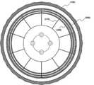
도 1은 본 발명의 실시예에 따른 플랙서블 압전소자를 이용한 자동차 타이어 적용 발전 장치의 전체 구성도를 도시하고 있다.FIG. 1 shows an overall configuration of an automotive tire-applied power generation device using a flexible piezoelectric device according to an embodiment of the present invention.
이를 참고하면, 본 발명에 따른 플랙서블 압전소자를 이용한 자동차 타이어 적용 발전 장치는, 내부가 비어있는 중공 튜브구조의 공기압 타이어(100); 상기 타이어(100)의 내면에 형성되는 링 형상의 내면 벽(200); 상기 내면 벽(200)을 지지하기 위하여 타이어(100)의 중심 및 내면 벽(200)의 내면을 연결하는 지지 프레임(210); 상기 내면 벽(200)의 외주면 전체에 고정 장착되어, 상기 타이어(100)가 지면과 접하여 수축될 시, 상기 내면 벽(200)과 타이어(100) 내면의 공간이 좁아짐으로써 압력을 받아 발전하는 플렉서블 압전소자(300);를 포함하는 것을 특징으로 한다.Referring to these figures, an automotive tire-applied power generation device using a flexible piezoelectric device according to the present invention comprises: a
구체적으로, 본 발명의 타이어(100)는 일반적으로 기존의 자동차용 타이어로 사용되는 중공 튜브구조의 공기압 타이어로써, 이러한 공기압 타이어의 경우, 내부가 비어 있으므로, 도 1에서와 같이, 본 발명을 위한 내면 벽(200)을 설치하는 공간이 제공된다.Specifically, the
이러한 내면 벽(200)은 도 1에서 보는 바와 같이, 타이어(100)내부의 중공 공간에 위치하면, 타이어(100)의 내부 림을 중심으로 링형상을 하여 설치된다.As shown in FIG. 1, when the
이러한 내면 벽(200)을 타이어(100)내부에 고정될 수 있도록 도 1과 같이 타이어(100)의 중심 림 및 내면 벽(200)의 내면을 서로 연결하여 지지 고정하는 지지 프레임(210)을 형성하게 된다.As shown in FIG. 1, a
이 때, 상기 지지 프레임(210)은, 신축성이 있는 재질로써, 도 2에서 보는 바와 같이, 상기 타이어(100)가 지면과 접하여 수축되어 상기 내면 벽(200)과 접촉 시, 같이 수축 됨으로써, 타이어(100)의 노면 충격 흡수 기능을 저해하지 않으면서, 내면 벽(200)의 위치를 지지하도록 한다.As shown in FIG. 2, the
즉, 상기 지지 프레임(210)이 신축성이 없는 경질의 재질이라면, 상기 타이어(100)가 지면과 접하여 수축될 시, 수축되는 타이어(100)의 내면을 밀어내게 되므로 타이어(100)의 본연의 기능인 노면의 충격흡수 기능을 저해하는 문제점이 있을 수 있다.That is, if the
따라서, 타이어(100)의 노면 충격흡수 기능을 위하여, 상기 지지 프레임(210)이신축성이 있는 고분자 합성수지재를 적용함으로써, 타이어(100)가 수출할 시, 타이어(100)의 내면을 압박하되, 강한 반탄력을 가지지 않도록 하여, 타이어(100)의 노면 충격흡수 기능 저하를 방지하는 것이 바람직하다.Therefore, when the
물론, 이러한 상기 지지 프레임(210)의 경우, 신축성을 가지는 고분자 수지 재질 외에도, 탄성력을 가지는, 스프링으로 대체가 가능하다.Of course, in the case of such a
다음으로, 도 3을 참고하면, 상기 내면 벽(200)은, 다층으로 형성되고, 각 내면 벽(200)과 내면 벽(200)사이의 공간에는 상기 플렉서블 압전소자(300)를 개재하여, 상기 타이어(100)가 지면과 접하여 수축됨으로써 상기 다수의 내면 벽(200)과 내면 벽(200) 사이에 개재된 다수의 상기 플렉서블 압전소자(300)가 동시에 가압되어 다중으로 전력을 생성하는 것이 가능하다.3, the
즉, 다수의 층을 이루는 내면 벽(200)과 벽 사이에 상기 플렉서블 압전소자(300)가 개재되고, 상기 타이어(100)가 지면과 접하여 수축할 시, 최상층의 내면 벽(200)이 다음 층의 내면 벽(200)을 가압하고, 가압된 내면 벽(200)이 다른 내면 벽(200)을 가압하는 방식으로 순차적 가압이 가능해지므로, 사이사이에 개재된 다수의 플렉서블 압전소자(300)층에서 전력 생산이 가능해 진다.That is, when the flexible
또한, 도 4에서 보는 바와 같이, 상기 내면 벽(200)은, 측면에 단면이 "U" 자 형상으로 휘어진 측면 지지판(220)을 추가로 형성하고, 상기 측면 지지판(220)의 외주면 전체에 상기 플렉서블 압전소자(300)를 장착할 수 있으며, 상기 측면 지지판(220)은, 탄성력을 가지는 소재로써, 상기 타이어(100)의 내부 측면에 대응되도록 휘어진 형상으로, 상기 타이어(100)가 지면과 접하여 수축될 시, 휘어짐이 증가하여 타이어(100)의 내부 측면과 밀착 압박하여, 상기 플렉서블 압전소자(300)를 가압하는 역할알 하는 부가 구성을 취할 수 있다.4, the
즉, 타이어(100)의 내부 측면에 대응되도록 휘어진 형상의 측면 지지판(220)이 타이어가 수축 할 시, 휘어짐이 증대되면서, 타이어(100)의 내면 쪽으로 밀착가압 됨으로써, 이러한 측면 지지판(220)의 외주면 전체에 장착된 플렉서블 압전소자(300)가 가압됨으로써, 추가적인 전력을 생성할 수 있다.That is, when the
따라서, 상기와 같은 내면 벽(200)의 다층 배열 및 측면 지지판(220)을 형성하는 것과 같은 부가 구성으로 인하여, 전력 생산 면적을 증대시킴으로써, 플렉서블 압전소자(300)의 발전 효율을 높여 더욱 많은 전력 생산이 가능해 진다.Accordingly, due to the additional structure such as the multilayer arrangement of the
상기와 같이 생산된 차량의 타이어(100)에서 집전된 전력은 차량의 배터리로 전달되는데, 배터리로 전달하는 과정에서, 전선을 사용할 경우 차량 타이어(100)의 회전에 의하여 전선이 꼬여 버리는 문제가 발생할 수 있다.The electric power collected from the
이를 방지하기 위하여 차량 타이어(100)의 집전부로부터 전력을 전달받는 전선에 꼬임 방지를 위한 구조가 구비되도록 할 수도 있고, 또는 차량 부품들이 대부분 전기적 전도가 가능한 금속 재질로 이루어지는 점을 이용, 차량의 연결 파트 부품들을 통해 전도가 이루어지도록 하여 꼬임 발생이 일어나지 않는 부분에 전선을 연결하는 등의 구조를 사용할 수도 있다.In order to prevent this, it is possible to provide a structure for preventing the twisted wire from being received from the current collecting part of the
또한, 상기 플렉서블 압전소자(300)로부터 모인 전력을 배터리로 전달할 수 있는 구조라면, 본 발명의 기술사상을 벗어나지 않는 범위 내에서 어떠한 구조를 사용하여도 무방하다.In addition, any structure may be used as long as it does not deviate from the technical idea of the present invention, provided that it can transfer power collected from the flexible
이상 본 발명의 실시예에 따른 도면을 참조하여 설명하였지만, 본 발명이 속한 분야에서 통상의 지식을 가진 자라면 상기 내용을 바탕으로 본 발명의 범주 내에서 다양한 응용 및 변형을 행하는 것이 가능할 것이다.While the present invention has been described with reference to exemplary embodiments, it is to be understood that the invention is not limited to the disclosed exemplary embodiments.
100 : 타이어
200 : 내면 벽
210 : 지지 프레임
220 : 측면 지지판
300 : 플렉서블 압전소자100: Tire
200: inner wall
210: Support frame
220: side support plate
300: Flexible piezoelectric element
Claims (5)
Translated fromKorean상기 타이어(100)의 내면에 형성되는 링 형상의 내면 벽(200);
상기 내면 벽(200)을 지지하기 위하여 타이어(100)의 중심 및 내면 벽의 내면을 연결하는 지지 프레임(210);
상기 내면 벽(200)의 외주면 전체에 고정 장착되어, 상기 타이어(100)가 지면과 접하여 수축될 시, 상기 내면 벽(200)과 타이어(100) 내면의 공간이 좁아짐으로써 압력을 받아 발전하는 플렉서블 압전소자(300);를 포함하되,
상기 지지 프레임(210)은, 신축성의 고분자 합성수지재로 구비되어, 상기 타이어(100)가 지면과 접하여 수축되어 상기 내면 벽(200)과 접촉 시, 같이 수축 됨으로써, 타이어(100)의 내면을 압박하되, 타이어(100)의 노면 충격 흡수 기능을 저해하지 않으면서, 내면 벽(200)의 위치를 지지하도록 하고,
상기 내면 벽(200)은, 다층으로 형성되고, 각 내면 벽(200)과 내면 벽(200)사이의 공간에는 상기 플렉서블 압전소자(300)를 개재하여, 상기 타이어(100)가 지면과 접하여 수축됨으로써 상기 다수의 내면 벽(200)과 내면 벽(200) 사이에 개재된 다수의 상기 플렉서블 압전소자(300)가 동시에 가압되어 다중으로 전력을 생성하는 것을 특징으로 하는 플랙서블 압전소자를 이용한 자동차 타이어 적용 발전 장치.
A pneumatic tire (100) having a hollow tube structure with an empty interior;
A ring-shaped inner wall 200 formed on the inner surface of the tire 100;
A support frame 210 connecting the center of the tire 100 and the inner surface of the inner wall to support the inner wall 200;
The inner surface of the inner wall 200 and the inner surface of the tire 100 are narrowed when the tire 100 is in contact with the ground so that the inner surface of the inner wall 200 is contracted. And a piezoelectric element (300)
The support frame 210 is made of a stretchable polymer synthetic resin material and contracts when the tire 100 comes into contact with the ground and contracts when it comes into contact with the inner wall 200 to thereby press the inner surface of the tire 100 The inner surface of the inner wall 200 is supported by the tire 100 without impeding the road surface shock absorbing function of the tire 100,
The inner wall 200 is formed in a multilayered structure and the space between the inner wall 200 and the inner wall 200 is connected to the tire 100 via the flexible piezoelectric element 300, Wherein a plurality of the flexible piezoelectric elements (300) sandwiched between the plurality of inner walls (200) and the inner wall (200) are simultaneously pressed to generate electric power in multiple. Applied Generator.
상기 지지 프레임(210)은, 스프링으로 대체 가능한 것을 특징으로 하는 플랙서블 압전소자를 이용한 자동차 타이어 적용 발전 장치.The method according to claim 1,
Wherein the support frame (210) is replaceable with a spring.
상기 내면 벽(200)은, 측면에 단면이 "U" 자 형상으로 휘어진 측면 지지판(220)을 추가로 형성하고, 상기 측면 지지판(220)의 외주면 전체에 상기 플렉서블 압전소자(300)를 장착할 수 있으며,
상기 측면 지지판(220)은, 탄성력을 가지는 소재로써, 상기 타이어(100)의 내부 측면에 대응되도록 휘어진 형상으로, 상기 타이어(100)가 지면과 접하여 수축될 시, 휘어짐이 증가하여 타이어(100)의 내부 측면과 밀착 압박하여, 상기 플렉서블 압전소자(300)를 가압하는 역할을 하는 것을 특징으로 하는 플랙서블 압전소자를 이용한 자동차 타이어 적용 발전 장치.The method according to claim 1,
The inner wall 200 is further formed with a side support plate 220 bent in a U-shaped cross section on its side and the flexible piezoelectric device 300 is mounted on the entire outer peripheral surface of the side support plate 220 And,
The side support plate 220 is bent to correspond to the inner side surface of the tire 100 and is bent when the tire 100 is in contact with the ground surface. And presses the flexible piezoelectric element (300) by pressing and pressing the inner side surface of the flexible piezoelectric element (300).
Priority Applications (2)
| Application Number | Priority Date | Filing Date | Title |
|---|---|---|---|
| KR1020150159369AKR101757065B1 (en) | 2015-11-13 | 2015-11-13 | Battery charger for vehicle using flexible piezoelectric element in tire |
| US14/952,965US10050566B2 (en) | 2015-11-13 | 2015-11-26 | Generator for automobile using flexible piezoelectric device |
Applications Claiming Priority (1)
| Application Number | Priority Date | Filing Date | Title |
|---|---|---|---|
| KR1020150159369AKR101757065B1 (en) | 2015-11-13 | 2015-11-13 | Battery charger for vehicle using flexible piezoelectric element in tire |
Publications (2)
| Publication Number | Publication Date |
|---|---|
| KR20170056147A KR20170056147A (en) | 2017-05-23 |
| KR101757065B1true KR101757065B1 (en) | 2017-07-26 |
Family
ID=58692094
Family Applications (1)
| Application Number | Title | Priority Date | Filing Date |
|---|---|---|---|
| KR1020150159369AExpired - Fee RelatedKR101757065B1 (en) | 2015-11-13 | 2015-11-13 | Battery charger for vehicle using flexible piezoelectric element in tire |
Country Status (2)
| Country | Link |
|---|---|
| US (1) | US10050566B2 (en) |
| KR (1) | KR101757065B1 (en) |
Cited By (1)
| Publication number | Priority date | Publication date | Assignee | Title |
|---|---|---|---|---|
| KR102070808B1 (en) | 2019-07-31 | 2020-01-30 | 강성선 | Pressure generator system and power generation method using it |
Families Citing this family (4)
| Publication number | Priority date | Publication date | Assignee | Title |
|---|---|---|---|---|
| US11791748B2 (en) | 2019-07-24 | 2023-10-17 | Tdk Corporation | Smart wheel energy harvester |
| KR102635117B1 (en)* | 2021-12-15 | 2024-02-13 | 넥센타이어 주식회사 | Tire and tire manufacturing method |
| JP2024092622A (en)* | 2022-12-26 | 2024-07-08 | 住友ゴム工業株式会社 | Tire Assembly |
| KR102610967B1 (en)* | 2023-04-03 | 2023-12-06 | 권병철 | a power generation device using tire deformation |
Citations (1)
| Publication number | Priority date | Publication date | Assignee | Title |
|---|---|---|---|---|
| JP2006223054A (en)* | 2005-02-10 | 2006-08-24 | Yokohama Rubber Co Ltd:The | Tire with power generator |
Family Cites Families (5)
| Publication number | Priority date | Publication date | Assignee | Title |
|---|---|---|---|---|
| KR19980028334U (en) | 1996-11-22 | 1998-08-05 | 박병재 | Battery Charger Using Piezoelectric Element |
| KR20030039692A (en) | 2001-11-14 | 2003-05-22 | 현대자동차주식회사 | Auxiliary generator using suspension in vehicle |
| US7429801B2 (en)* | 2002-05-10 | 2008-09-30 | Michelin Richerche Et Technique S.A. | System and method for generating electric power from a rotating tire's mechanical energy |
| DE102007010780B4 (en)* | 2006-03-02 | 2016-01-28 | Continental Teves Ag & Co. Ohg | Tire module with piezoelectric transducer |
| JP4482916B1 (en) | 2009-08-06 | 2010-06-16 | 有限会社 加納 | Power generator |
- 2015
- 2015-11-13KRKR1020150159369Apatent/KR101757065B1/ennot_activeExpired - Fee Related
- 2015-11-26USUS14/952,965patent/US10050566B2/ennot_activeExpired - Fee Related
Patent Citations (1)
| Publication number | Priority date | Publication date | Assignee | Title |
|---|---|---|---|---|
| JP2006223054A (en)* | 2005-02-10 | 2006-08-24 | Yokohama Rubber Co Ltd:The | Tire with power generator |
Cited By (1)
| Publication number | Priority date | Publication date | Assignee | Title |
|---|---|---|---|---|
| KR102070808B1 (en) | 2019-07-31 | 2020-01-30 | 강성선 | Pressure generator system and power generation method using it |
Also Published As
| Publication number | Publication date |
|---|---|
| KR20170056147A (en) | 2017-05-23 |
| US10050566B2 (en) | 2018-08-14 |
| US20170141703A1 (en) | 2017-05-18 |
Similar Documents
| Publication | Publication Date | Title |
|---|---|---|
| KR101757065B1 (en) | Battery charger for vehicle using flexible piezoelectric element in tire | |
| JP4359901B1 (en) | Power generator | |
| CN103889786A (en) | Vehicle charging device | |
| EP1848103B1 (en) | Tire with electric-power generation device | |
| CN102806817A (en) | Vehicle with active-regenerative suspension | |
| US9385636B2 (en) | Transport vehicle, charging system and electricity-generating tire | |
| JP4482916B1 (en) | Power generator | |
| US20170084817A1 (en) | Piezoelectric Power Generating Tire Apparatus | |
| KR101189723B1 (en) | Generator using a load weighing down a tire | |
| KR101326584B1 (en) | Electric energy obtaining device and tire having it and energy supplying method using it | |
| JP5248458B2 (en) | Double structure tire power generator | |
| KR20190011882A (en) | Generating Device Using Brake System and Generating Method thereof | |
| JP2006115662A (en) | Energy conversion device and movable body equipped therewith | |
| JP2018517598A (en) | Tire structure combined with spikes | |
| KR100784281B1 (en) | Electromagnetic Fluid Pneumatic Tires to Alleviate Durability Loss | |
| CN107819411B (en) | Passive pressure power generation device based on piezoelectric rubber | |
| US9694690B2 (en) | Method and apparatus for generation, transmission and storage of electric energy | |
| US20220376636A1 (en) | Piezoelectric energy harvesting system for use in vehicle | |
| CN103216562A (en) | Air spring shock mitigation system capable of recycling energy | |
| KR20140002382A (en) | Generator using a load weighing down a tire | |
| KR20130012290A (en) | Self-generator using car rubber spring | |
| KR101238278B1 (en) | Shock absorber for vehicle including linear generator | |
| RU2748097C2 (en) | Method for partial recycling of energy of a moving car and variants of design of apparatus for implementation thereof | |
| KR20190040390A (en) | Tire built-in piezoelectric generation and apparatus using vehicle load | |
| WO2016093679A2 (en) | Vehicular piezoelectric generator device |
Legal Events
| Date | Code | Title | Description |
|---|---|---|---|
| A201 | Request for examination | ||
| PA0109 | Patent application | St.27 status event code:A-0-1-A10-A12-nap-PA0109 | |
| PA0201 | Request for examination | St.27 status event code:A-1-2-D10-D11-exm-PA0201 | |
| PN2301 | Change of applicant | St.27 status event code:A-3-3-R10-R13-asn-PN2301 St.27 status event code:A-3-3-R10-R11-asn-PN2301 | |
| PN2301 | Change of applicant | St.27 status event code:A-3-3-R10-R13-asn-PN2301 St.27 status event code:A-3-3-R10-R11-asn-PN2301 | |
| D13-X000 | Search requested | St.27 status event code:A-1-2-D10-D13-srh-X000 | |
| D14-X000 | Search report completed | St.27 status event code:A-1-2-D10-D14-srh-X000 | |
| E902 | Notification of reason for refusal | ||
| PE0902 | Notice of grounds for rejection | St.27 status event code:A-1-2-D10-D21-exm-PE0902 | |
| E13-X000 | Pre-grant limitation requested | St.27 status event code:A-2-3-E10-E13-lim-X000 | |
| P11-X000 | Amendment of application requested | St.27 status event code:A-2-2-P10-P11-nap-X000 | |
| P13-X000 | Application amended | St.27 status event code:A-2-2-P10-P13-nap-X000 | |
| PG1501 | Laying open of application | St.27 status event code:A-1-1-Q10-Q12-nap-PG1501 | |
| E701 | Decision to grant or registration of patent right | ||
| PE0701 | Decision of registration | St.27 status event code:A-1-2-D10-D22-exm-PE0701 | |
| GRNT | Written decision to grant | ||
| PR0701 | Registration of establishment | St.27 status event code:A-2-4-F10-F11-exm-PR0701 | |
| PR1002 | Payment of registration fee | St.27 status event code:A-2-2-U10-U11-oth-PR1002 Fee payment year number:1 | |
| PG1601 | Publication of registration | St.27 status event code:A-4-4-Q10-Q13-nap-PG1601 | |
| P22-X000 | Classification modified | St.27 status event code:A-4-4-P10-P22-nap-X000 | |
| PR1001 | Payment of annual fee | St.27 status event code:A-4-4-U10-U11-oth-PR1001 Fee payment year number:4 | |
| PC1903 | Unpaid annual fee | St.27 status event code:A-4-4-U10-U13-oth-PC1903 Not in force date:20210706 Payment event data comment text:Termination Category : DEFAULT_OF_REGISTRATION_FEE | |
| PC1903 | Unpaid annual fee | St.27 status event code:N-4-6-H10-H13-oth-PC1903 Ip right cessation event data comment text:Termination Category : DEFAULT_OF_REGISTRATION_FEE Not in force date:20210706 | |
| P22-X000 | Classification modified | St.27 status event code:A-4-4-P10-P22-nap-X000 | |
| P22-X000 | Classification modified | St.27 status event code:A-4-4-P10-P22-nap-X000 |