KR101756762B1 - Method for manufacturing laser welded steel pipe - Google Patents
Method for manufacturing laser welded steel pipeDownload PDFInfo
- Publication number
- KR101756762B1 KR101756762B1KR1020167001316AKR20167001316AKR101756762B1KR 101756762 B1KR101756762 B1KR 101756762B1KR 1020167001316 AKR1020167001316 AKR 1020167001316AKR 20167001316 AKR20167001316 AKR 20167001316AKR 101756762 B1KR101756762 B1KR 101756762B1
- Authority
- KR
- South Korea
- Prior art keywords
- laser
- pipe
- welding
- open pipe
- laser beam
- Prior art date
- Legal status (The legal status is an assumption and is not a legal conclusion. Google has not performed a legal analysis and makes no representation as to the accuracy of the status listed.)
- Expired - Fee Related
Links
Images


Classifications
- B—PERFORMING OPERATIONS; TRANSPORTING
- B23—MACHINE TOOLS; METAL-WORKING NOT OTHERWISE PROVIDED FOR
- B23K—SOLDERING OR UNSOLDERING; WELDING; CLADDING OR PLATING BY SOLDERING OR WELDING; CUTTING BY APPLYING HEAT LOCALLY, e.g. FLAME CUTTING; WORKING BY LASER BEAM
- B23K26/00—Working by laser beam, e.g. welding, cutting or boring
- B23K26/20—Bonding
- B23K26/21—Bonding by welding
- B23K26/24—Seam welding
- B—PERFORMING OPERATIONS; TRANSPORTING
- B21—MECHANICAL METAL-WORKING WITHOUT ESSENTIALLY REMOVING MATERIAL; PUNCHING METAL
- B21C—MANUFACTURE OF METAL SHEETS, WIRE, RODS, TUBES, PROFILES OR LIKE SEMI-MANUFACTURED PRODUCTS OTHERWISE THAN BY ROLLING; AUXILIARY OPERATIONS USED IN CONNECTION WITH METAL-WORKING WITHOUT ESSENTIALLY REMOVING MATERIAL
- B21C37/00—Manufacture of metal sheets, rods, wire, tubes, profiles or like semi-manufactured products, not otherwise provided for; Manufacture of tubes of special shape
- B21C37/06—Manufacture of metal sheets, rods, wire, tubes, profiles or like semi-manufactured products, not otherwise provided for; Manufacture of tubes of special shape of tubes or metal hoses; Combined procedures for making tubes, e.g. for making multi-wall tubes
- B21C37/08—Making tubes with welded or soldered seams
- B—PERFORMING OPERATIONS; TRANSPORTING
- B23—MACHINE TOOLS; METAL-WORKING NOT OTHERWISE PROVIDED FOR
- B23K—SOLDERING OR UNSOLDERING; WELDING; CLADDING OR PLATING BY SOLDERING OR WELDING; CUTTING BY APPLYING HEAT LOCALLY, e.g. FLAME CUTTING; WORKING BY LASER BEAM
- B23K26/00—Working by laser beam, e.g. welding, cutting or boring
- B23K26/02—Positioning or observing the workpiece, e.g. with respect to the point of impact; Aligning, aiming or focusing the laser beam
- B23K26/06—Shaping the laser beam, e.g. by masks or multi-focusing
- B23K26/0604—Shaping the laser beam, e.g. by masks or multi-focusing by a combination of beams
- B23K26/0608—Shaping the laser beam, e.g. by masks or multi-focusing by a combination of beams in the same heat affected zone [HAZ]
- B—PERFORMING OPERATIONS; TRANSPORTING
- B23—MACHINE TOOLS; METAL-WORKING NOT OTHERWISE PROVIDED FOR
- B23K—SOLDERING OR UNSOLDERING; WELDING; CLADDING OR PLATING BY SOLDERING OR WELDING; CUTTING BY APPLYING HEAT LOCALLY, e.g. FLAME CUTTING; WORKING BY LASER BEAM
- B23K26/00—Working by laser beam, e.g. welding, cutting or boring
- B23K26/20—Bonding
- B23K26/21—Bonding by welding
- B23K26/24—Seam welding
- B23K26/26—Seam welding of rectilinear seams
- B23K26/262—Seam welding of rectilinear seams of longitudinal seams of tubes
- B—PERFORMING OPERATIONS; TRANSPORTING
- B23—MACHINE TOOLS; METAL-WORKING NOT OTHERWISE PROVIDED FOR
- B23K—SOLDERING OR UNSOLDERING; WELDING; CLADDING OR PLATING BY SOLDERING OR WELDING; CUTTING BY APPLYING HEAT LOCALLY, e.g. FLAME CUTTING; WORKING BY LASER BEAM
- B23K2101/00—Articles made by soldering, welding or cutting
- B23K2101/04—Tubular or hollow articles
- B23K2101/06—Tubes
- B—PERFORMING OPERATIONS; TRANSPORTING
- B23—MACHINE TOOLS; METAL-WORKING NOT OTHERWISE PROVIDED FOR
- B23K—SOLDERING OR UNSOLDERING; WELDING; CLADDING OR PLATING BY SOLDERING OR WELDING; CUTTING BY APPLYING HEAT LOCALLY, e.g. FLAME CUTTING; WORKING BY LASER BEAM
- B23K2103/00—Materials to be soldered, welded or cut
- B23K2103/02—Iron or ferrous alloys
- B23K2103/04—Steel or steel alloys
Landscapes
- Engineering & Computer Science (AREA)
- Physics & Mathematics (AREA)
- Optics & Photonics (AREA)
- Mechanical Engineering (AREA)
- Plasma & Fusion (AREA)
- Laser Beam Processing (AREA)
Abstract
Translated fromKorean
Description
Translated fromKorean본 발명은, 레이저 빔(laser beam)을 이용하여 오픈 파이프(open pipe)의 길이 방향의 에지부(longitudinal edges)를 용접하는 강관(이하, 레이저 용접 강관(laser welded steel pipe)이라고 함)의 제조 방법에 관한 것으로, 특히 유정관(oil country tubular goods) 혹은 라인 파이프(line pipe) 등의 석유, 천연 가스의 채굴이나 수송에 적합한 레이저 용접 강관의 제조 방법에 관한 것이다.The present invention relates to a method of manufacturing a steel pipe (hereinafter referred to as a laser welded steel pipe) which welds longitudinal longitudinal edges of an open pipe using a laser beam The present invention relates to a method of manufacturing a laser welded steel pipe suitable for mining and transporting oil and natural gas such as oil country tubular goods or line pipe.
유정관 혹은 라인 파이프로서 이용되는 강관은, 용접 강관(welded steel pipe)(예를 들면 전봉 강관(electric resistance welded steel pipe), UOE 강관 등)과 시임리스(seamless) 강관으로 크게 나뉜다. 이들 강관 중, 전봉 강관은, 열간 압연한 띠 형상의 강판(steel strip)(소위 핫 코일(hot rolled steel coil))을 소재로서 사용하여, 염가로 제조할 수 있기 때문에 경제적으로 유리하다.The steel pipe used as a fluid pipe or a line pipe is largely divided into a welded steel pipe (for example, an electric resistance welded steel pipe, a UOE steel pipe, and the like) and a seamless steel pipe. Among these steel pipes, the steel pipe is economically advantageous because it can be manufactured at a low cost by using a steel strip (hot rolled steel coil) which is hot rolled strip steel.
그러나 일반적으로 전봉 강관은, 성형 롤을 이용하여 강판을 원통 형상으로 성형하여 오픈 파이프(여기에서 오픈 파이프란, 다단(multiple)의 성형 롤에 의해 성형된 단부(端部)가 접합되어 있지 않은 파이프 형상의 강대(steel strip)를 가리킴. 이하, 오픈 파이프라고 기재함)로 하고, 그 오픈 파이프의 에지부(즉 원통 형상으로 성형한 강대의 양측 단부)를 스퀴즈 롤(squeeze roll)로 가압하면서 전기 저항 용접(electric resistance welding, 고주파 저항 용접이라고도 부름)하여 제조하기 때문에, 용접에 의한 이음매(소위 시임(seam))가 필연적으로 존재하며, 그 시임의 저온 인성(low-temperature toughness)이 열화된다는 문제가 있다. 그 때문에 전봉 강관의 유정관이나 라인 파이프는, 한랭지(cold district)에서의 사용에는 과제가 있다. 시임의 저온 인성이 열화되는 이유는, 에지부를 용접할 때에 고온의 용융 메탈(molten metal)이 대기 중의 산소와 반응하여 산화물(oxide)을 생성하고, 그 산화물이 시임에 잔류하기 쉽기 때문이다.However, in general, the electro-plated steel pipe is formed by forming a steel plate into a cylindrical shape using a forming roll and forming an open pipe (here, an open pipe is a pipe which is not bonded to an end portion formed by a multiple forming roll) (Hereinafter, referred to as an open pipe), and an edge portion of the open pipe (i.e., both side ends of a cylindrical formed steel strip) is pressed by a squeeze roll, Because it is manufactured by electric resistance welding (also called high-frequency resistance welding), there is a problem that weld seams (so-called seams) are inevitably present and the low-temperature toughness of the seams is deteriorated . For this reason, there is a problem in the use of the oil pipe and line pipe of the steel pipe in the cold district. The reason why the low-temperature toughness of the seam is deteriorated is because molten metal of high temperature reacts with oxygen in the atmosphere to generate oxide when welding the edge portion, and the oxide tends to remain in the seam.
또한 전봉 강관은, 에지부를 용접할 때에 용융 메탈 중에서 합금 원소(alloy element)가 편석(偏析)하기 쉽기 때문에, 시임의 내식성이 열화되기 쉽다는 문제가 있다. 그 때문에 전봉 강관의 유정관이나 라인 파이프는, 엄격한 부식 환경(corrosion environment)(예를 들면 사워 환경(sour environment))에서의 사용에는 과제가 있다.In addition, there is a problem in that when the edge portion is welded, the alloy steel element is likely to segregate in the molten metal, so that the corrosion resistance of the seam is liable to deteriorate. For this reason, the oil pipe and line pipe of the steel pipe are challenged for use in a severe corrosion environment (for example, a sour environment).
한편으로 시임의 저온 인성이나 내식성을 열화시키지 않는 용접법으로서, 레이저 빔에 의한 용접(이하, 레이저 용접(laser welding)이라고 함)이 주목되고 있다. 레이저 용접은, 열원(heat source)의 치수를 작게 하고, 또한 열에너지(heat energy)를 고밀도로 집중할 수 있기 때문에, 용융 메탈에 있어서의 산화물의 생성이나 합금 원소의 편석을 방지할 수 있다. 그 때문에, 용접 강관의 제조에 레이저 용접을 적용하면, 시임의 저온 인성이나 내식성의 열화를 방지하는 것이 가능하다.On the other hand, as a welding method that does not deteriorate low-temperature toughness and corrosion resistance of a seam, welding with a laser beam (hereinafter referred to as laser welding) is attracting attention. Laser welding can reduce the size of a heat source and concentrate heat energy at a high density, so that generation of oxides and segregation of alloying elements in the molten metal can be prevented. Therefore, when laser welding is applied to the manufacture of welded steel tubes, deterioration of the low temperature toughness and corrosion resistance of the seam can be prevented.
그래서 용접 강관의 제조 과정에서, 오픈 파이프의 에지부에 레이저 빔을 조사하여 용접함으로써 강관(즉 레이저 용접 강관)을 제조하는 기술이 실용화되고 있다.Therefore, in the manufacturing process of the welded steel pipe, a technique of manufacturing a steel pipe (that is, a laser welded steel pipe) by irradiating a laser beam to the edge portion of the open pipe for welding has been put to practical use.
그런데 레이저 용접에서는, 고밀도 에너지 광선(high-energy density light beam)인 레이저 빔을 광학 부품(optical component)에 의해 집광하여 용접부에 조사함으로써 용접을 행하기 때문에, 용접시에 급격한 금속의 용융을 수반한다. 그 때문에, 형성된 용융지(溶融池;molten weld pool)로부터 용융 메탈이 스패터(spatter)로서 비산한다. 비산한 스패터는, 용접 장치(welding equipment)에 부착되어 시임의 품질을 저하시킴과 함께, 광학 부품에도 부착되어 용접의 시공이 불안정해진다. 또한, 레이저 용접에서는 열에너지(heat energy)를 고밀도로 집중하여 용접을 행하기 때문에, 스패터가 다량으로 발생하여, 언더컷(undercut)이나 언더필(underfill)(즉 패임(depression)) 등의 용접 결함(welding defect)이 발생한다. 언더필이 발생하면, 용접부의 강도가 저하된다.However, in the laser welding, since the laser beam, which is a high-energy density light beam, is focused by an optical component and irradiated to the welded portion, the abraded metal is melted at the time of welding . Therefore, the molten metal spattered from the formed molten weld pool as a spatter. The scattered spatter adheres to the welding equipment, deteriorates the quality of the seam, and is adhered to the optical parts, so that the construction of the welding becomes unstable. Further, in laser welding, welding is performed by concentrating heat energy at a high density, so that a large amount of spatters are generated and welding defects such as undercuts and underfills (i.e., depressions) welding defect occurs. If underfilling occurs, the strength of the welded portion is lowered.
그래서, 레이저 용접에서 스패터의 부착을 방지하는 기술이나 스패터의 발생을 방지하는 기술이 여러 가지 검토되고 있다. 예를 들면, 레이저 출력(laser power)을 저감함으로써 스패터의 발생을 방지하는 기술, 혹은 초점 위치(focus position)를 크게 어긋나게 (소위 디포커스(defocus))함으로써 스패터의 발생을 방지하는 기술이 실용화되고 있다. 그러나, 레이저 출력의 저감이나 디포커스는, 용접 속도(welding speed)의 감소(즉 용접 효율(weld efficiency)의 저하)를 초래할 뿐만 아니라, 용입 불량(lack of penetration)이 발생하기 쉬워진다는 문제가 있다.Therefore, various techniques for preventing the attachment of the spatter and for preventing the occurrence of the spatter in laser welding have been studied. For example, a technique for preventing the generation of spatter by reducing the laser power, or a technique for preventing the generation of spatter by largely shifting the focus position (so-called defocus) Has been practically used. However, the reduction or defocusing of the laser output causes not only a decrease in the welding speed (i.e., a decrease in the welding efficiency) but also a tendency that the lack of penetration is liable to occur have.
특허문헌 1에는, 레이저 빔을 분광하여 복수개의 레이저 빔 스폿(laser beam spots)을 생성시켜 스패터의 발생을 방지하는 기술이 개시되어 있다. 그러나, 복수개의 빔 스폿에 분산시켜 레이저 용접을 행하는 기술은, 레이저 출력을 저감하여 레이저 용접을 행하는 기술과 동등하며, 용접 효율의 저하를 초래할 뿐만 아니라, 용입 불량이 발생하기 쉬워진다는 문제가 있다. 게다가, 레이저 빔을 분광하는 프리즘(prism)이 고가이기 때문에, 용접의 시공 비용이 상승하는 것은 피할 수 없다.
특허문헌 2에서는, 레이저 용접을 행할 때에 필러 와이어(filler wire)를 이용하여 용착 금속(deposit metal)의 부족(언더필)을 방지하는 기술이 개시되어 있다. 그러나, 이 기술에서는 필러 와이어의 성분에 의해 용접 금속(weld metal)의 조성이 변화한다. 그 때문에, 오픈 파이프의 성분에 따라서 필러 와이어를 선택하지 않으면 안 되고, 필러 와이어의 재고 관리(stock management)나 레이저 용접의 작업 관리(production control)의 부하가 증대된다.
특허문헌 3에서는, 레이저 용접과 아크 용접(arc welding)을 복합하여 이용함으로써, 용접 결함을 방지하는 기술이 개시되어 있다. 그러나, 이 기술에서는 용접 장치의 구조가 복잡해져 메인터넌스(maintenance)의 부하가 증대될 뿐만 아니라, 용접의 작업 관리의 부하가 증대된다.
본 발명은, 레이저 용접 강관을 제조함에 있어서, 복수개의 레이저 빔의 조사에 의해 가열 용융하는 복수의 부위(즉 스폿)를 적정하게 배열함과 함께, 오픈 파이프의 상면(강판 표면)에서의 스폿 지름이나 스폿 길이를 적정하게 유지하여, 오픈 파이프의 외표면에 있어서의 에너지 밀도를 제어함으로써, 언더컷이나 언더필을 방지하고, 또한 양호한 품질의 레이저 용접 강관을 높은 수율(yield ratio)로 효율 좋게 제조하는 방법을 제공하는 것을 목적으로 한다.In manufacturing a laser welded steel pipe, a plurality of portions (that is, spots) to be heated and melted by irradiation of a plurality of laser beams are appropriately arranged, and the spot diameter on the upper surface (steel plate surface) Or the spot length is appropriately maintained to control the energy density on the outer surface of the open pipe to thereby prevent undercut and underfill and to efficiently manufacture a laser welded steel pipe of good quality with a high yield ratio And to provide the above objects.
발명자들은, 오픈 파이프의 에지부에 레이저 용접을 행하여 레이저 용접 강관을 제조함에 있어서, 레이저 용접의 용접 현상(welding phenomenon)의 안정화 기술(stabilization technology)에 대해서 조사 검토했다.The inventors investigated the stabilization technology of the welding phenomenon of the laser welding in manufacturing the laser welded steel pipe by laser welding to the edge of the open pipe.
도 1은, 레이저 용접 강관을 제조할 때에, 레이저 빔을 1개 이용하여 오픈 파이프(1)의 에지부(2)의 접합점을 용접하는 종래의 예를 개략적으로 나타내는 사시도이다. 도 1 중의 화살표 A는, 오픈 파이프의 진행 방향(traveling direction)을 나타낸다. 또한, 레이저 빔(3)의 조사에 의해 발생하는 깊은 공동(cavity)(이하, 키홀(keyhole)이라고 함)(4)과, 그 주변에 형성되는 용융 메탈(5)은 투시도로서 나타낸다. 그리고 레이저 빔(3)을 조사하면, 도 1에 나타내는 바와 같이, 고밀도로 집중되는 열에너지에 의해 에지부(2)가 용융함과 함께, 그 용융 메탈(5)이 증발하여 발생하는 증발압(evporating pressure)과 증발 반력(reaction force)에 의해, 용융 메탈(5)에 키홀(4)이 발생한다. 키홀(4)의 내부에는, 레이저 빔(3)이 침입하여, 금속 증기(metal vapour)가 레이저 빔(3)의 에너지에 의해 전리(電離)되어 발생한 고온의 플라즈마(plasma)가 충만하고 있다고 생각된다.1 is a perspective view schematically showing a conventional example of welding a joint point of an
이 키홀(4)은, 레이저 빔(3)의 열에너지가 가장 수렴하는 위치를 나타내는 것이다. 에지부의 접합점을 키홀(4) 내에 배치함으로써 레이저 용접 강관을 안정되게 제조할 수 있다. 단, 에지부(2)의 접합점과 키홀(4)을 일치시키기 위해서는, 고(高)정밀도의 위치 제어 기술이 필요하다. 에지부(2)의 가공 상태 및 맞댐 상태가 불안정하면, 용융 메탈(5)이 불안정해진다. 그 결과, 스패터가 많이 발생하여, 언더컷이나 언더필 등의 용접 결함이 발생하기 쉬워진다. 그래서 에지부(2)의 접합점에 조사하는 레이저 빔의 에너지 밀도를 조정한다. 그러기 위해서는, 레이저 빔의 스폿 지름, 스폿 형상, 스폿 개수를 적정하게 유지하거나, 혹은 레이저 빔의 초점 위치를 변화시킨다. 또한, 레이저 빔을 접합점으로부터 어긋난 위치에 조사한다.The
이러한 스폿의 형태의 조정은, 적정한 집광 렌즈(collection lens or focusing lens)나 집광 미러(collection mirror or focusing mirror)를 제작함으로써 가능한 기술이다.Such adjustment of the shape of the spot is possible by making a collection lens or a focusing lens or a collection mirror or focusing mirror.
본 발명은, 이들 인식에 기초하여 이루어진 것이다.The present invention is based on these perceptions.
즉 본 발명은, 강판을 성형 롤로 원통 형상의 오픈 파이프로 성형하고, 오픈 파이프의 에지부를 스퀴즈 롤로 가압하면서 오픈 파이프의 외면측으로부터 레이저 빔을 조사하여 에지부를 용접하는 레이저 용접 강관의 제조 방법에 있어서, 오픈 파이프의 상면(강판 표면)에서의 스폿 지름이 0.3㎜ 이상인 복수개의 레이저 빔을 이용하여, 복수개의 레이저 빔의 강판 표면에서의 용접선에 대하여 수직 방향의 스폿 지름(이후, 스폿 길이라고 칭함)의 합계가 0.5㎜ 이상, 용접선 방향의 스폿 중심 간 거리를 5㎜ 이내로 배열하여 용접을 행하는 레이저 용접 강관의 제조 방법이다.That is, the present invention provides a method of manufacturing a laser welded steel pipe in which a steel sheet is formed into a cylindrical open pipe by a forming roll, and the edge portion is welded by irradiating a laser beam from the outer surface side of the open pipe while pressing the edge portion of the open pipe with a squeeze roll (Hereinafter referred to as a spot length) with respect to a weld line on the surface of a steel sheet of a plurality of laser beams using a plurality of laser beams having a spot diameter of 0.3 mm or more on the upper surface (steel plate surface) of the open pipe, Is 0.5 mm or more and the distance between the centers of the spots in the weld line direction is 5 mm or less.
본 발명의 레이저 용접 강관의 제조 방법에 있어서는, 오픈 파이프의 외표면에 있어서의 각 레이저 빔의 에너지 밀도가 70㎾/㎟ 이하인 것이 바람직하다. 또한, 오픈 파이프의 두께를 T로 하고, 오픈 파이프의 외표면으로부터 3T∼-3T에 초점 위치를 배치하는 것이 바람직하다. 또한, 복수개의 레이저 빔의 레이저 출력을 합계 15㎾ 이상, 용접 속도를 7m/분 이상으로 하는 것이 바람직하다. 레이저 빔에 전진각 5∼50° (파이프 표면에 수직 방향으로부터 용접 진행 방향의 역방향으로의 각도를 전진각이라고 칭함)를 부여하는 것이 바람직하다. 오픈 파이프의 두께 T는 3㎜를 초과하는 것이 바람직하다. 오픈 파이프의 에지부를 스퀴즈 롤로 가압함에 있어서, 0.3∼1.0㎜의 업셋(upset)이 바람직하다.In the method of manufacturing a laser welded steel pipe of the present invention, it is preferable that the energy density of each laser beam on the outer surface of the open pipe is 70 kW /
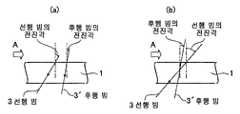
또한, 용접선 방향으로 후행 빔을 배치하는 경우는, 후행 빔의 전진각은, 선행 빔보다도 전진각을 작게 하는 것이 바람직하다.In the case of arranging the trailing beam in the weld line direction, it is preferable that the advancing angle of the trailing beam is smaller than that of the preceding beam.
본 발명에 의하면, 레이저 용접 강관을 제조함에 있어서 복수개의 레이저 빔의 조사에 의해 가열 용융하는 복수의 부위(즉 스폿)를 적정하게 배열함과 함께, 오픈 파이프의 상면(강판 표면)에서의 스폿 지름이나 스폿 길이를 적정하게 유지하고, 오픈 파이프의 외표면에 있어서의 에너지 밀도를 제어함으로써, 언더컷이나 언더필을 방지하고, 또한 레이저 용접 강관을 수율 좋게 안정적으로 제조할 수 있다. 얻어진 레이저 용접 강관은, 시임의 저온 인성이나 내식성이 우수하여, 한랭지나 부식 환경에서 사용하는 유정관이나 라인 파이프에 적합하다.According to the present invention, in manufacturing a laser welded steel pipe, a plurality of portions (i.e., spots) to be heated and melted by irradiation of a plurality of laser beams are appropriately arranged and the spot diameter And the spot length are appropriately maintained and the energy density on the outer surface of the open pipe is controlled to prevent undercut and underfilling and to stably manufacture the laser welded steel pipe with good yield. The obtained laser welded steel pipe is excellent in low temperature toughness and corrosion resistance of the seam, and is suitable for a flow pipe or a line pipe used in a cold or corrosive environment.
도 1은 오픈 파이프의 에지부의 접합점을 용접하는 종래의 예를 개략적으로 나타내는 사시도이다.
도 2는 본 발명을 적용하여 복수개의 레이저 빔을 조사하는 위치를 개략적으로 나타내는 평면도이다.
도 3은 본 발명을 적용하여 오픈 파이프의 에지부의 접합점을 용접하는 예를 개략적으로 나타내는 사시도이다.
도 4는 개개의 레이저 빔의 강판 표면에서의 용접선에 대하여 수직 방향의 스폿 길이의 합계와 용접선 방향의 스폿 중심 간 거리를 나타내는 도면이다.
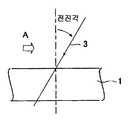
도 5는 본 발명의 레이저 빔의 전진각의 관계를 개략적으로 나타내는 도면이다.
도 6은 본 발명의 선행 빔과 후행 빔의 전진각의 관계를 개략적으로 나타내는 도면이다.1 is a perspective view schematically showing a conventional example of welding a joint point of an edge portion of an open pipe.
Fig. 2 is a plan view schematically showing a position where a plurality of laser beams are irradiated by applying the present invention. Fig.
Fig. 3 is a perspective view schematically showing an example of welding the junction of the edge portion of the open pipe by applying the present invention. Fig.
4 is a diagram showing the sum of the spot lengths in the vertical direction with respect to the weld line on the surface of the steel sheet of each laser beam and the distance between the centers of the spots in the weld line direction.
5 is a view schematically showing the relationship of the advancing angle of the laser beam according to the present invention.
6 is a view schematically showing the relationship between the advance angle of the preceding beam and the trailing beam of the present invention.
(발명을 실시하기 위한 형태)(Mode for carrying out the invention)
본 발명에서는, 복수개의 레이저 빔을 이용하여 레이저 용접 강관을 제조한다. 레이저 빔을 2개 이용하는 예를 도 3에 나타낸다. 도 3에서는 오픈 파이프(1)의 에지부(2)를 스퀴즈 롤(도시하지 않음)로 가압하면서, 외면측으로부터 레이저 빔(3)을 2개 조사한다. 도 3 중의 화살표 A는 오픈 파이프(1)의 진행 방향을 나타낸다. 또한, 레이저 빔(3)의 조사에 의해 발생하는 키홀(4)과 그 주위에 형성되는 용융 메탈(5)은 투시도로서 나타낸다.In the present invention, a laser welded steel pipe is manufactured by using a plurality of laser beams. An example of using two laser beams is shown in Fig. 3, two
(1) 오픈 파이프 상면(강판 표면)에 있어서의 레이저 빔의 조사 위치와 에지부의 위치(1) The irradiation position of the laser beam on the upper surface of the open pipe (steel plate surface) and the position of the edge portion
2개 이상의 레이저 빔(3)을 조사하는 위치의 예를 도 2에 평면도로서 나타낸다. 도 2 중의 화살표 A는 오픈 파이프(1)의 진행 방향을 나타낸다.An example of a position for irradiating two or
도 2(a)는, 2개의 레이저 빔을 조사하는 위치를 나타내고 있으며, 동일한 스폿 지름의 레이저 빔(3-1, 3-2)을 에지부(2)의 양측에 배치하는 예이다. 이 예를 사시도로 나타낸 것이 도 3이다.2 (a) shows an example in which two laser beams are irradiated, and laser beams 3-1 and 3-2 having the same spot diameter are arranged on both sides of the
도 2(b)는, 3개의 레이저 빔을 조사하는 위치를 나타내고 있으며, 스폿 지름이 작은 레이저 빔(3-1)으로 예열하고, 동일한 스폿 지름의 레이저 빔(3-2, 3-3)을 에지부(2)의 양측에 배치하는 예이다.Fig. 2 (b) shows a position for irradiating three laser beams. The laser beams 3-2 and 3-3 having the same spot diameter are pre-heated by a laser beam 3-1 having a small spot diameter Are arranged on both sides of the edge portion (2).
도 2(c)는, 4개의 레이저 빔을 조사하는 위치를 나타내고 있으며, 동일한 스폿 지름의 레이저 빔(3-1, 3-2, 3-3, 3-4)을 에지부(2)의 양측에 각각 2개씩 배치하는 예이다.2 (c) shows the positions for irradiating four laser beams, and laser beams 3-1, 3-2, 3-3 and 3-4 having the same spot diameter are arranged on both sides of the
도 2(d)는, 2개의 레이저 빔을 조사하는 위치를 나타내고 있으며, 스폿 지름이 상이한 레이저 빔(3-1, 3-2)을 에지부(2)의 양측에 배치하는 예이다. 이 예에서는 레이저 빔(3-1)의 스폿 지름이 작기 때문에, 레이저 빔(3-1)을 레이저 빔(3-2)보다 에지부(2)에 근접하여 배치하고 있다.2 (d) shows an example in which the laser beams 3-1 and 3-2 having different spot diameters are arranged on both sides of the
도 2(e)는, 2개의 레이저 빔을 조사하는 위치를 나타내고 있으며, 레이저 빔(3-1, 3-2)을 에지부(2)를 따라 배치하는 예이다. 이 예에서는 레이저 빔(3-2)의 스폿 지름이 작다.Fig. 2 (e) shows an example in which two laser beams are irradiated, and the laser beams 3-1 and 3-2 are arranged along the
복수개의 레이저 빔을 이용하는 경우의 레이저 빔의 배치는, 도 2에 나타내는 예로 한정하는 것이 아니며, 목적에 따라서 적절하게 배치할 수 있다. 단, 레이저 빔을 5개 이상 사용하면, 용접 장치의 구조가 복잡해져, 메인터넌스의 부하가 커진다. 그 때문에, 레이저 빔을 2∼4개 사용하는 것이 바람직하다.The arrangement of the laser beams in the case of using a plurality of laser beams is not limited to the example shown in Fig. 2, and can be appropriately arranged in accordance with the purpose. However, if five or more laser beams are used, the structure of the welding apparatus becomes complicated, and the load of the maintenance becomes large. Therefore, it is preferable to use 2 to 4 laser beams.
(2) 오픈 파이프 상면(강판 표면)에서의 스폿 지름(2) Spot diameter on the upper surface of the open pipe (steel plate surface)
복수개의 레이저 빔을 이용하여, 개개의 레이저 빔의 오픈 파이프의 상면(강판 표면)에서의 스폿 지름이 0.3㎜ 이상이, 바람직하다. 스폿 지름이 0.3㎜ 미만이면 안정된 키홀의 유지가 어려워지기 때문이다. 또한, 오픈 파이프 상면(강판 표면)에서의 스폿 지름의 상한은, 1.0㎜이다.It is preferable that the spot diameter on the upper surface (steel plate surface) of the open pipe of each laser beam is 0.3 mm or more by using a plurality of laser beams. If the spot diameter is less than 0.3 mm, it is difficult to maintain a stable keyhole. The upper limit of the spot diameter on the upper face of the open pipe (steel plate surface) is 1.0 mm.
(3) 오픈 파이프 상면(강판 표면)에서의 스폿 길이 및 스폿 중심 간 거리(3) Distance between the spot length and the center of the spot on the upper surface of the open pipe (steel plate surface)
도 4에 나타내는 바와 같이, 복수개의 레이저 빔을 이용하여, 개개의 레이저 빔의 강판 표면에서의 용접선에 대하여 수직 방향의 스폿 길이의 합계를 0.5㎜ 이상으로 하고, 용접선 방향의 스폿 중심 간 거리를 5㎜ 이내로 한다. 스폿 길이의 합계를 0.5㎜ 이상으로 함으로써, 접합점을 용융 메탈(5) 내에 비교적 용이하게 배치하는 것이 가능해진다. 또한, 스폿 중심 간 거리를 5㎜ 이내로 함으로써, 용융 메탈(5)의 분리를 방지하는 것이 가능해진다. 또한, 용접선에 대하여 수직 방향의 스폿 길이 및 스폿 중심 간 거리의 정의를, 구체적으로 도 4에 나타낸다.4, the sum of the spot lengths in the vertical direction with respect to the weld line on the surface of the steel sheet of each laser beam is set to 0.5 mm or more and the distance between the centers of the spots in the weld line direction is set to 5 Mm. By setting the sum of the spot lengths to 0.5 mm or more, it becomes possible to relatively easily arrange the bonding points in the
(4) 레이저 빔의 에너지 밀도(4) The energy density of the laser beam
오픈 파이프(1)의 외표면에 있어서의 개개의 레이저 빔(3)의 에너지 밀도는 70㎾/㎟ 이하가 바람직하다. 단순히 레이저 빔(3)을 디포커스하면 용입 특성이 열화되기 때문에, 에너지 밀도의 하한값을 1㎾/㎟ 이상으로 규정함으로써 용입 특성의 열화를 방지한다. 단, 에너지 밀도가 70㎾/㎟를 초과하면, 오픈 파이프(1)의 외표면으로부터의 스패터 발생량이 증가한다. 또한, 레이저 빔(3)의 에너지 밀도는, 레이저 출력 및 스폿 지름을 제어함으로써 조정한다.The energy density of the
(5) 오픈 파이프의 상면(강판 표면)으로부터 초점 위치까지의 거리(5) Distance from the upper surface (steel plate surface) of the open pipe to the focus position
오픈 파이프의 상면으로부터 초점 위치까지의 거리를 t(㎜)로 하고, 오픈 파이프의 강판 두께를 T(㎜)로 하여, 오픈 파이프의 상면으로부터 포커스까지의 거리 t가 3×T(즉 상면으로부터 상방으로 3T)를 초과하면, 포커스의 위치가 지나치게 높기 때문에, 키홀을 안정되게 유지하는 것이 어렵다. 한편, -3×T(즉 상면으로부터 하방으로 3T)를 초과하면, 포커스의 위치가 지나치게 깊기 때문에, 강판의 이면(裏面)(즉 오픈 파이프의 내면)측으로부터 스패터가 발생하기 쉬워진다. 따라서, 오픈 파이프의 상면으로부터 포커스까지의 거리 t는 -3×T∼3×T의 범위 내로 설정하는 것이 바람직하다. 또한, 선행 레이저 빔(3a) 및 후행 레이저 빔(3b)의 강판의 상면으로부터 포커스까지의 거리는, 키홀의 안정성의 관점에서, 일치시키는 것이 바람직하다.The distance t from the top surface of the open pipe to the focus is 3 x T (that is, the distance from the top surface to the top surface is t (mm), the thickness of the open pipe is T (mm) 3T), it is difficult to keep the keyhole stably because the focus position is too high. On the other hand, if it exceeds -3 × T (that is, 3T downward from the top surface), since the position of the focus is excessively deep, spatter is likely to be generated from the back surface (ie, the inner surface of the open pipe) side of the steel sheet. Therefore, it is desirable to set the distance t from the top surface of the open pipe to the focus within a range of -3 x T to 3 x T. It is preferable that the distances from the upper surface of the steel sheet of the preceding laser beam 3a and the trailing laser beam 3b to the focus coincide with each other from the viewpoint of stability of the keyhole.
(6) 오픈 파이프의 두께(6) Thickness of open pipe
오픈 파이프(1)의 두께 T는 3㎜ 초과가 바람직하다. 두께 T가 3㎜ 이하에서는, 산화가 발생하기 쉬워진다.The thickness T of the
(7) 레이저 출력이나 용접 속도(7) Laser output or welding speed
일반적으로, 레이저 용접에서 발생하는 스패터는, 레이저 출력이 낮을수록, 혹은 용접 속도가 늦을수록 감소한다. 그러나, 스패터의 발생을 억제하기 위해, 레이저 출력이나 용접 속도를 조정하는 것은, 레이저 용접 강관의 생산성의 저하를 초래함과 함께, 블로우홀(blowhole)이 발생하기 쉬워진다는 문제가 있다. 따라서, 복수개의 레이저 빔(3)의 레이저 출력을 합계 15㎾ 이상으로 하고, 또한 용접 속도를 7m/분 이상으로 하는 것이, 생산성 향상 및 블로우홀 억제의 관점에서 바람직하다. 레이저 출력이 합계 15㎾ 미만에서는 용접 속도가 7m/분 미만으로 저하되기 때문에, 생산성이 저하되어, 블로우홀이 발생한다.Generally, the spatter generated in laser welding decreases as the laser output is lower or as the welding speed is slower. However, adjusting the laser output or the welding speed to suppress the generation of the spatter has a problem that the productivity of the laser welded steel pipe is lowered and the blowhole is easily generated. Therefore, it is preferable that the total laser output of the plurality of
(8) 레이저 빔의 초점 거리(8) The focal length of the laser beam
각각의 레이저 빔(3)의 초점 거리는 200㎜ 이상이 바람직하다. 초점 거리가 200㎜ 미만에서는, 오픈 파이프(1)의 에지부(2)의 Z축 방향(즉 레이저 빔의 광축 방향)으로 초점 위치가 변동함으로써, 레이저 용접이 불안정해진다.The focal length of each
(9) 레이저 빔의 전진각(9) The advance angle of the laser beam
레이저 빔(3)을 조사하는 각도(이하, 전진각이라고 함)는, 도 5에 나타내는 바와 같이, 5∼50°의 범위 내가 바람직하다. 전진각을 형성하여 레이저 빔(3)을 조사함으로써, 스패터의 발생량이 감소한다. 단, 전진각이 5° 미만에서는 그 효과가 얻어지지 않는다. 또한, 50°를 초과해도 그 효과는 얻어지지 않는다. 보다 바람직하게는, 15°∼45°이다. 또한, 도 6에 나타내는 바와 같이, 용접선 방향으로 후행 빔을 배치하는 경우, 후행 빔의 전진각은, 선행 빔보다도 전진각을 작게 하는 것이 바람직하다. 여기에서, 선행 빔은, 강판의 하면에 있어서 용접선 방향으로 선행하는 빔을 의미한다. 또한, 도 5 중 및 도 6 중의 화살표 A는 오픈 파이프(1)의 진행 방향을 나타낸다.The angle at which the
(10) 업셋량(10) Upset
레이저 용접에 의한 스패터의 발생을 전혀 없애는 것은 곤란하기 때문에, 언더컷이나 언더필의 발생을 방지하기 위해, 에지부(2)에 0.3∼1.0㎜의 업셋을 부여하는 것이 바람직하다. 업셋량이 0.3㎜ 미만에서는, 언더컷이나 언더필을 방지할 수 없다. 한편, 1.0㎜를 초과하면, 시임(6)의 손질에 많은 시간을 필요로 한다.It is difficult to eliminate generation of spatter caused by laser welding. Therefore, in order to prevent occurrence of undercut and underfill, it is preferable to apply an upset of 0.3 to 1.0 mm to the
(11) 에지부의 접합점(11) Junction point of the edge portion
오픈 파이프(1)의 진행 방향 A에 있어서의 에지부(2)의 접합점은, 에지부(2)의 평균 간격이 스퀴즈 롤(도시하지 않음)에 의해 좁아져, 0.5㎜ 이하가 된 개소라면 어디라도 좋다.The joining point of the
(12) 레이저 빔의 발진기(12) Oscillator of laser beam
본 발명에서 사용하는 레이저 빔의 발진기(oscillator)는, 여러 가지 형태의 발진기를 사용할 수 있고, 기체(예를 들면 CO2(carbon dioxide gas), 헬륨 네온(helium-neon), 아르곤(argon), 질소(nitrogen), 요오드(iodine) 등)를 매질로서 이용하는 기체 레이저(gas laser), 고체(예를 들면 희토류(希土類) 원소를 도프(dope)한 YAG 등)를 매질로서 이용하는 고체 레이저(solid laser), 레이저 매질(laser medium)로서 벌크(bulk) 대신에 파이버(fiber)를 이용하는 파이버 레이저(fiber laser), 디스크 레이저(disk laser) 등이 적합하다. 혹은, 반도체 레이저(semiconductor laser)를 사용해도 좋다.Oscillator (oscillator) of the laser beam used in the present invention may be used for various types of oscillators, gas (e.g. CO2 (carbon dioxide gas), helium-neon (helium-neon), Ar (argon), Solid lasers using a gas laser as a medium or a solid such as YAG doped with a rare earth element as a medium as a medium such as nitrogen or iodine, Fiber lasers using a fiber instead of bulk as a laser medium, disk lasers, and the like are suitable. Alternatively, a semiconductor laser may be used.
(13) 보조 열원(13) Auxiliary heat source
오픈 파이프(1)의 외면측으로부터 보조 열원(auxiliary heat source)에 의해 가열해도 좋다. 그 보조 열원은, 오픈 파이프(1)의 외표면을 가열하여 용융할 수 있는 것이라면, 그의 구성은 특별히 한정하지 않는다. 예를 들면, 버너 용해법(burner melting method), 플라즈마 용해법(plasma melting method), TIG 용해법(Tungsten Inert Gas melting method), 전자 빔 용해법(electron beam melting method), 레이저 용해법(leser beam melting method) 등을 이용한 수단이 적합하다.It may be heated by an auxiliary heat source from the outer surface side of the
단 보조 열원으로서는 아크의 사용이 가장 바람직하다. 아크의 발생원은, 용융 메탈(5)의 용락(burn through)을 억제하는 방향으로 전자력(즉 용접 전류의 자계(磁界)로부터 발생하는 전자력)을 부가할 수 있는 것을 사용한다. 예를 들면 TIG 용접법, 플라즈마 아크 용접법 등의 종래부터 알려져 있는 기술을 사용할 수 있다. 아크의 발생원은 레이저 빔과 일체적으로 배치하는 것이 바람직하다. 그 이유는, 아크를 발생시키는 용접 전류의 주변에 발생하는 자계의 영향을, 용융 메탈(5)에 효과적으로 부여하기 때문이다. 또한, 아크의 발생원을 레이저 빔(3)보다 선행시켜 배치하는 것이 한층 바람직하다. 그 이유는, 에지부(2)의 수분이나 유분을 제거할 수 있기 때문이다.However, arc is most preferable as the auxiliary heat source. The source of the arc is one capable of adding an electromagnetic force (that is, an electromagnetic force generated from a magnetic field of a welding current) in a direction to suppress the burn through of the
아크 이외의 보조 열원을 사용하는 경우도, 보조 열원은 레이저 빔(3)의 발진기와 일체적으로 배치하는 것이 바람직하다. 그 이유는, 보조 열원과 레이저를 일체적으로 배치하지 않으면, 보조 열원의 효과를 얻기 위해서는 큰 열량이 필요해지고, 또한 용접 결함(예를 들면 언더컷 등)의 억제가 매우 곤란해지기 때문이다. 또한, 보조 열원을 레이저 빔(3)의 발진기보다 선행시켜 배치하는 것이 한층 바람직하다. 그 이유는, 에지부(2)의 수분이나 유분을 제거할 수 있기 때문이다.Even when an auxiliary heat source other than an arc is used, it is preferable that the auxiliary heat source is disposed integrally with the oscillator of the
본 발명에서는, 후육재(厚肉材)(예를 들면 두께 4㎜ 이상)의 오픈 파이프(1)라도, 에지부(2)를 고주파 가열(high-frequency induction heating) 등으로 예열하는 일 없이, 레이저 용접을 행하는 것이 가능하다. 단 에지부(2)를 예열하면, 레이저 용접 강관의 생산성이 향상되는 등의 효과가 얻어진다.In the present invention, even if the
이상으로 설명한 바와 같이, 본 발명에 의하면, 큰 에너지를 갖는 레이저 용접에 의해 레이저 용접 강관을 제조함에 있어서, 언더컷이나 언더필을 억제함과 함께, 용접 효율을 저하시키는 일 없이 양호한 품질의 레이저 용접 강관을 수율 좋게 얻을 수 있다. 얻어진 레이저 용접 강관은, 시임(6)의 저온 인성이나 내식성이 우수하여, 한랭지나 부식 환경에서 사용하는 유정관이나 라인 파이프에 적합하다.INDUSTRIAL APPLICABILITY As described above, according to the present invention, in manufacturing a laser welded steel pipe by laser welding with a large energy, the undercut and underfill can be suppressed and the laser welded steel pipe of good quality can be obtained The yield can be improved. The obtained laser welded steel pipe is excellent in low temperature toughness and corrosion resistance of the
[실시예][Example]
띠 형상의 강판을 성형 롤로 원통 형상의 오픈 파이프로 성형하고, 그 오픈 파이프의 에지부를 스퀴즈 롤로 가압하면서, 레이저 빔을 외면측으로부터 조사하여 레이저 용접 강관을 제조했다. 강판의 성분은 표 1에 나타내는 바와 같다.A laser welded steel pipe was produced by forming a strip-shaped steel sheet into a cylindrical open pipe with a forming roll and irradiating the laser beam from the outer side while pressing the edge portion of the open pipe with a squeeze roll. The components of the steel sheet are shown in Table 1.
레이저 용접에서는, 10㎾의 파이버 레이저 발진기를 2대 사용했다. 그 출력과 용접 속도는 표 2에 나타내는 바와 같다.In laser welding, two 10 kW fiber laser oscillators were used. The output and the welding speed are shown in Table 2.
표 2에 나타내는 발명예는, 본원 발명의 필수의 요건을 만족하는 예이다. 또한, 발명예 중 강관 No.10은 용접 속도가 본 발명의 적합 범위를 벗어나는 예, 강관 No.11은 레이저 출력이 본 발명의 적합 범위를 벗어나는 예, 강관 No.12는 업셋량이 본 발명의 적합 범위를 벗어나는 예, 강관 No.13은 에너지 밀도가 본 발명의 적합 범위를 벗어나는 예이다. 이들은, 모두 본원 발명의 필수의 요건을 만족하기 때문에 발명예로 한다.The inventive example shown in Table 2 is an example satisfying the essential requirements of the present invention. The steel tube No. 11 is an example in which the laser output is out of the preferable range of the present invention. The steel tube No. 12 is an example in which the amount of upset is the fit of the present invention For example, the steel pipe No. 13 is an example in which the energy density deviates from the preferable range of the present invention. These are all examples because they satisfy the essential requirements of the present invention.
비교예 중, 강관 No.7은 스폿 지름이 본 발명의 범위를 벗어나는 예, 강관 No.7,8은 스폿 길이가 본 발명의 범위를 벗어나는 예, 강관 No.9는 스폿 중심 간 거리가 본 발명의 범위를 벗어나는 예, 강관 No.14,15는 하나의 레이저 빔을 이용한 예이다.In the comparative examples, the steel pipe No. 7 is an example in which the spot diameter is out of the range of the present invention, the steel pipe No. 7 or 8 is an example in which the spot length is out of the range of the present invention, For example, steel tubes Nos. 14 and 15 use one laser beam.
얻어진 레이저 용접 강관을, 초음파 탐상 시험(ultrasonic inspection test)에 제공하고, JIS 규격 G0582에 준거하여 시임을 20m에 걸쳐 탐상했다. 그 탐상 결과를 표 2에 나타낸다. 또한 표 2에 있어서는, 기준이 되는 N5 내외면 노치(notch)의 인공 결함(artificial defect)에 대하여, 피크 지시 높이가, 10% 이하인 것을 우수(◎), 10% 초과 25% 이하인 것을 양호(○), 25% 초과 50% 이하인 것을 가능(△), 50% 초과인 것을 불가(×)로 하여 평가했다.The obtained laser welded steel pipe was provided to an ultrasonic inspection test, and the seam was scanned over 20 m in accordance with JIS standard G0582. The results of the flaw detection are shown in Table 2. In Table 2, it is preferable that the peak indication height is 10% or less (⊚) and 10% or more and 25% or less (artificial defect) of the N5 inner and outer surface notch ), It is possible that it is more than 25% but not more than 50% (△), and it is impossible (x) that it is more than 50%.
표 2로부터 분명한 바와 같이, 발명예에서는, 초음파 탐상은 우수(◎), 양호(○) 또는 가능(△)이었다. 또한, 스패터의 발생에 의한 언더컷이나 언더필 등의 용접 결함은 확인되지 않았다. 한편, 비교예에서는, 초음파 탐상은 불가(×)였다. 또한, 언더컷이나 언더필 등의 용접 결함이 확인되었다. 발명예 중 강관 No.13에도, 언더컷이나 언더필이 근소하게나마 확인되었다.As is clear from Table 2, in the inventive example, the ultrasonic inspection was excellent (?), Good (?) Or feasible (?). Further, welding defects such as undercut and underfill caused by the generation of spatter were not observed. On the other hand, in the comparative example, ultrasonic inspection was impossible (X). In addition, weld defects such as undercut and underfill were confirmed. Also undercuts and underfill were confirmed in the steel pipe No.13 during the demonstration.
(산업상 이용가능성)(Industrial applicability)
레이저 용접 강관을 수율 좋게 안정적으로 제조할 수 있고, 얻어진 레이저 용접 강관은, 시임의 저온 인성이나 내식성이 우수하여, 한랭지나 부식 환경에서 사용하는 유정관이나 라인 파이프에 적합하기 때문에, 산업상 각별한 효과를 나타낸다.The laser welded steel pipe can be stably produced with good yield and the obtained laser welded steel pipe is excellent in low temperature toughness and corrosion resistance of the seam and is suitable for a reflux pipe or a line pipe used in a cold or corrosive environment, .
1 : 오픈 파이프
2 : 에지부
3 : 레이저 빔
4 : 키홀
5 : 용융 메탈
6 : 시임
(표 1)
(표 2)
2: edge portion
3: laser beam
4: Keyhole
5: molten metal
6: Seam
(Table 1)
(Table 2)
Claims (2)
Translated fromKorean(A) 상기 오픈 파이프의 외표면에 있어서의 상기 각 레이저 빔의 에너지 밀도를 70kW/mm2 이하로 함
(B) 상기 복수개의 레이저 빔의 레이저 출력을 합계 15kW 이상, 용접 속도를 7m/분 이상으로 함
(C) 상기 오픈 파이프의 두께 T가 3mm를 초과함
(D) 상기 오픈 파이프의 에지부를 스퀴즈 롤로 가압함에 있어서, 0.3∼1.0mm의 업셋을 부여함
The method of manufacturing a laser welded steel pipe according to claim 1, further comprising one or more groups selected from the group consisting of (A) to (D) below.
(A) the energy density of each of the laser beams on the outer surface of the open pipe is 70 kW / mm2 or less
(B) The laser output of the plurality of laser beams is 15 kW or more in total and the welding speed is 7 m / min or more
(C) The thickness T of the open pipe exceeds 3 mm
(D) When pushing the edge portion of the open pipe with the squeeze roll, an upset of 0.3 to 1.0 mm is given
Applications Claiming Priority (1)
| Application Number | Priority Date | Filing Date | Title |
|---|---|---|---|
| PCT/JP2011/060805WO2012147213A1 (en) | 2011-04-28 | 2011-04-28 | Method for producing laser welded steel pipe |
Related Parent Applications (1)
| Application Number | Title | Priority Date | Filing Date |
|---|---|---|---|
| KR1020137030035ADivisionKR20130138338A (en) | 2011-04-28 | 2011-04-28 | Method for producing laser welded steel pipe |
Publications (2)
| Publication Number | Publication Date |
|---|---|
| KR20160013260A KR20160013260A (en) | 2016-02-03 |
| KR101756762B1true KR101756762B1 (en) | 2017-07-12 |
Family
ID=47071752
Family Applications (2)
| Application Number | Title | Priority Date | Filing Date |
|---|---|---|---|
| KR1020137030035ACeasedKR20130138338A (en) | 2011-04-28 | 2011-04-28 | Method for producing laser welded steel pipe |
| KR1020167001316AExpired - Fee RelatedKR101756762B1 (en) | 2011-04-28 | 2011-04-28 | Method for manufacturing laser welded steel pipe |
Family Applications Before (1)
| Application Number | Title | Priority Date | Filing Date |
|---|---|---|---|
| KR1020137030035ACeasedKR20130138338A (en) | 2011-04-28 | 2011-04-28 | Method for producing laser welded steel pipe |
Country Status (6)
| Country | Link |
|---|---|
| US (1) | US20140175069A1 (en) |
| EP (1) | EP2703112B1 (en) |
| KR (2) | KR20130138338A (en) |
| CN (1) | CN103501955B (en) |
| RU (1) | RU2563067C2 (en) |
| WO (1) | WO2012147213A1 (en) |
Families Citing this family (7)
| Publication number | Priority date | Publication date | Assignee | Title |
|---|---|---|---|---|
| WO2019130043A1 (en)* | 2017-12-26 | 2019-07-04 | Arcelormittal | Method for butt laser welding two metal sheets with first and second front laser beams and a back laser beam |
| JP6935484B2 (en)* | 2017-03-03 | 2021-09-15 | 古河電気工業株式会社 | Welding method and welding equipment |
| RU2697548C1 (en)* | 2018-11-06 | 2019-08-15 | федеральное государственное бюджетное образовательное учреждение высшего образования "Донской государственный технический университет" (ДГТУ) | Method of friction welding with mixing |
| RU2708715C1 (en)* | 2018-11-22 | 2019-12-11 | Общество с ограниченной ответственностью "Арк-инжиниринг" | Method for hybrid laser-arc surfacing of metal articles |
| CN113631319B (en)* | 2019-03-27 | 2024-02-27 | 株式会社博迈立铖 | Method and apparatus for manufacturing welded pipe |
| CN111673279A (en)* | 2020-06-08 | 2020-09-18 | 首钢集团有限公司 | A kind of steel plate laser welding method with aluminum or aluminum alloy coating, laser welding device and application |
| CN117283141A (en)* | 2023-11-15 | 2023-12-26 | 江苏优美特工程技术有限公司 | High-frequency induction laser composite welding process and welding equipment for steel pipes |
Citations (1)
| Publication number | Priority date | Publication date | Assignee | Title |
|---|---|---|---|---|
| JP2003088968A (en)* | 2001-09-17 | 2003-03-25 | Honda Motor Co Ltd | Work welding method |
Family Cites Families (26)
| Publication number | Priority date | Publication date | Assignee | Title |
|---|---|---|---|---|
| DE3632952A1 (en)* | 1986-09-27 | 1988-04-07 | Hoesch Ag | METHOD AND DEVICE FOR THE CONTINUOUS PRODUCTION OF TUBULAR BODIES BY LASER LENGTH SEAL WELDING |
| JPH0199789A (en)* | 1987-10-13 | 1989-04-18 | Kawasaki Steel Corp | Manufacture of welded pipe |
| JP2828879B2 (en)* | 1993-08-30 | 1998-11-25 | 住友重機械工業株式会社 | Laser processing machine |
| JP2902550B2 (en) | 1994-01-25 | 1999-06-07 | 住友重機械工業株式会社 | Laser processing machine |
| JP2836498B2 (en)* | 1994-09-19 | 1998-12-14 | 住友金属工業株式会社 | Laser welding pipe making method |
| JP2861836B2 (en)* | 1994-12-02 | 1999-02-24 | 住友金属工業株式会社 | Laser welding method for ferritic stainless steel |
| JPH08300172A (en)* | 1995-04-28 | 1996-11-19 | Nkk Corp | Manufacturing method of welded steel pipe |
| JP3079962B2 (en)* | 1995-07-12 | 2000-08-21 | 日本鋼管株式会社 | Manufacturing method of welded steel pipe |
| RU2108178C1 (en)* | 1996-08-28 | 1998-04-10 | Акционерное общество открытого типа "НовосибирскНИИХиммаш" | Method for welding tubes of clad band |
| WO1998025727A1 (en)* | 1996-12-10 | 1998-06-18 | Obschestvo S Ogranichennoi Otvetstvennostju 'lastr' | Method for manufacturing longitudinally welded pipes by laser welding and structure for implementation of the method |
| AU4498300A (en)* | 1999-04-30 | 2000-11-17 | Edison Welding Institute | Coated material welding with multiple energy beams |
| JP4395217B2 (en)* | 1999-05-17 | 2010-01-06 | 株式会社アマダエンジニアリングセンター | Composite head for laser welding |
| JP2003340582A (en)* | 2002-05-23 | 2003-12-02 | Mitsubishi Heavy Ind Ltd | Apparatus and method for laser welding |
| JP4120408B2 (en) | 2003-01-21 | 2008-07-16 | Jfeエンジニアリング株式会社 | Laser and arc combined welding method and groove shape of welded joint used therefor |
| JP2004330299A (en) | 2003-04-15 | 2004-11-25 | Nippon Steel Corp | Laser welding method with excellent weld strength |
| KR100489692B1 (en)* | 2004-06-16 | 2005-05-17 | 엘에스전선 주식회사 | Continuous butt welding method using plasma and laser, and fabricating method for metal tube using the same |
| US8253062B2 (en)* | 2005-06-10 | 2012-08-28 | Chrysler Group Llc | System and methodology for zero-gap welding |
| FR2908677B1 (en)* | 2006-11-17 | 2009-02-20 | Air Liquide | LASER BEAM WELDING METHOD WITH ENHANCED PENETRATION |
| JP2009178768A (en)* | 2008-02-01 | 2009-08-13 | Sumitomo Metal Ind Ltd | Laser welding method and laser welding apparatus |
| EP2322312B1 (en)* | 2008-06-23 | 2020-01-08 | JFE Steel Corporation | Method for manufacturing laser-welded steel pipe |
| JP5375527B2 (en)* | 2008-10-31 | 2013-12-25 | Jfeスチール株式会社 | Laser welded steel pipe manufacturing method |
| CN101412153B (en)* | 2008-11-07 | 2011-03-16 | 北京智博高科生物技术有限公司 | Process and equipment for welding sealing thin-wall metal tube using laser technique |
| JP2010167435A (en)* | 2009-01-21 | 2010-08-05 | Tokyu Car Corp | Laser welding method |
| CN101850472A (en)* | 2009-03-31 | 2010-10-06 | 武汉楚天激光(集团)股份有限公司 | Process method for welding aluminum and aluminum alloy material by laser |
| JP5827454B2 (en)* | 2010-03-08 | 2015-12-02 | 株式会社神戸製鋼所 | Laser / arc combined welding method and welded member manufacturing method using the welding method |
| CN101817119B (en)* | 2010-05-20 | 2012-04-25 | 什邡市明日宇航工业股份有限公司 | Laser welding method for rhenium alloy sheet |
- 2011
- 2011-04-28CNCN201180070463.XApatent/CN103501955B/ennot_activeExpired - Fee Related
- 2011-04-28WOPCT/JP2011/060805patent/WO2012147213A1/enactiveApplication Filing
- 2011-04-28KRKR1020137030035Apatent/KR20130138338A/ennot_activeCeased
- 2011-04-28USUS14/113,652patent/US20140175069A1/ennot_activeAbandoned
- 2011-04-28KRKR1020167001316Apatent/KR101756762B1/ennot_activeExpired - Fee Related
- 2011-04-28RURU2013152770/02Apatent/RU2563067C2/ennot_activeIP Right Cessation
- 2011-04-28EPEP11864197.6Apatent/EP2703112B1/ennot_activeNot-in-force
Patent Citations (1)
| Publication number | Priority date | Publication date | Assignee | Title |
|---|---|---|---|---|
| JP2003088968A (en)* | 2001-09-17 | 2003-03-25 | Honda Motor Co Ltd | Work welding method |
Also Published As
| Publication number | Publication date |
|---|---|
| EP2703112A1 (en) | 2014-03-05 |
| EP2703112A4 (en) | 2014-11-05 |
| CN103501955A (en) | 2014-01-08 |
| CN103501955B (en) | 2016-03-16 |
| KR20130138338A (en) | 2013-12-18 |
| RU2013152770A (en) | 2015-06-10 |
| KR20160013260A (en) | 2016-02-03 |
| US20140175069A1 (en) | 2014-06-26 |
| RU2563067C2 (en) | 2015-09-20 |
| EP2703112B1 (en) | 2018-01-10 |
| WO2012147213A1 (en) | 2012-11-01 |
Similar Documents
| Publication | Publication Date | Title |
|---|---|---|
| JP5024475B1 (en) | Laser welded steel pipe manufacturing method | |
| KR101756762B1 (en) | Method for manufacturing laser welded steel pipe | |
| JP5866790B2 (en) | Laser welded steel pipe manufacturing method | |
| KR101436705B1 (en) | Laser/arc hybrid welding method and method of producing welded member using same | |
| US4546230A (en) | Welding process using laser beam | |
| CN107999916B (en) | A kind of compound silk filling melt-brazing method of the double light beam laser-TIG of dissimilar material | |
| JP5954009B2 (en) | Manufacturing method of welded steel pipe | |
| JP3767369B2 (en) | Method of lap welding of thin steel plates and welded thin steel plates | |
| JP2012206145A (en) | Hot wire laser welding method and apparatus | |
| JP4978121B2 (en) | Butt joining method of metal plates | |
| JP5803160B2 (en) | Laser welded steel pipe manufacturing method | |
| JP2002144064A (en) | Method and apparatus for welding metal members | |
| JP5724294B2 (en) | Laser welded steel pipe manufacturing method | |
| JP3767374B2 (en) | Butt welding method and welded thin steel plate | |
| JP3767359B2 (en) | Butt welding method and welded thin steel plate | |
| JP2011173161A (en) | Laser welded steel pipe manufacturing method | |
| Booth | Manufacturing with Lasers, Developments and Opportunities | |
| Staufer et al. | Hybrid welding for the automotive industry Combining the laser beam with an arc for welding processes has been known since the 1970s. Recently, researchers have again turned their attention to this topic to unite the advantages of the arc and the laser, in a hybrid weld process, where they influence and support one another |
Legal Events
| Date | Code | Title | Description |
|---|---|---|---|
| A107 | Divisional application of patent | ||
| A201 | Request for examination | ||
| PA0104 | Divisional application for international application | St.27 status event code:A-0-1-A10-A16-div-PA0104 St.27 status event code:A-0-1-A10-A18-div-PA0104 | |
| PA0201 | Request for examination | St.27 status event code:A-1-2-D10-D11-exm-PA0201 | |
| PG1501 | Laying open of application | St.27 status event code:A-1-1-Q10-Q12-nap-PG1501 | |
| E902 | Notification of reason for refusal | ||
| PE0902 | Notice of grounds for rejection | St.27 status event code:A-1-2-D10-D21-exm-PE0902 | |
| T11-X000 | Administrative time limit extension requested | St.27 status event code:U-3-3-T10-T11-oth-X000 | |
| T11-X000 | Administrative time limit extension requested | St.27 status event code:U-3-3-T10-T11-oth-X000 | |
| T11-X000 | Administrative time limit extension requested | St.27 status event code:U-3-3-T10-T11-oth-X000 | |
| T11-X000 | Administrative time limit extension requested | St.27 status event code:U-3-3-T10-T11-oth-X000 | |
| E601 | Decision to refuse application | ||
| PE0601 | Decision on rejection of patent | St.27 status event code:N-2-6-B10-B15-exm-PE0601 | |
| T11-X000 | Administrative time limit extension requested | St.27 status event code:U-3-3-T10-T11-oth-X000 | |
| T13-X000 | Administrative time limit extension granted | St.27 status event code:U-3-3-T10-T13-oth-X000 | |
| AMND | Amendment | ||
| P11-X000 | Amendment of application requested | St.27 status event code:A-2-2-P10-P11-nap-X000 | |
| P13-X000 | Application amended | St.27 status event code:A-2-2-P10-P13-nap-X000 | |
| PX0901 | Re-examination | St.27 status event code:A-2-3-E10-E12-rex-PX0901 | |
| PX0701 | Decision of registration after re-examination | St.27 status event code:A-3-4-F10-F13-rex-PX0701 | |
| X701 | Decision to grant (after re-examination) | ||
| GRNT | Written decision to grant | ||
| PR0701 | Registration of establishment | St.27 status event code:A-2-4-F10-F11-exm-PR0701 | |
| PR1002 | Payment of registration fee | Fee payment year number:1 St.27 status event code:A-2-2-U10-U12-oth-PR1002 | |
| PG1601 | Publication of registration | St.27 status event code:A-4-4-Q10-Q13-nap-PG1601 | |
| PC1903 | Unpaid annual fee | Not in force date:20200706 Payment event data comment text:Termination Category : DEFAULT_OF_REGISTRATION_FEE St.27 status event code:A-4-4-U10-U13-oth-PC1903 | |
| PC1903 | Unpaid annual fee | Ip right cessation event data comment text:Termination Category : DEFAULT_OF_REGISTRATION_FEE Not in force date:20200706 St.27 status event code:N-4-6-H10-H13-oth-PC1903 |