KR101755630B1 - Meibomian photographing gland device using infrared ray - Google Patents
Meibomian photographing gland device using infrared rayDownload PDFInfo
- Publication number
- KR101755630B1 KR101755630B1KR1020160093665AKR20160093665AKR101755630B1KR 101755630 B1KR101755630 B1KR 101755630B1KR 1020160093665 AKR1020160093665 AKR 1020160093665AKR 20160093665 AKR20160093665 AKR 20160093665AKR 101755630 B1KR101755630 B1KR 101755630B1
- Authority
- KR
- South Korea
- Prior art keywords
- light source
- unit
- photographing
- filter
- spring
- Prior art date
- Legal status (The legal status is an assumption and is not a legal conclusion. Google has not performed a legal analysis and makes no representation as to the accuracy of the status listed.)
- Expired - Fee Related
Links
Images


Classifications
- A—HUMAN NECESSITIES
- A61—MEDICAL OR VETERINARY SCIENCE; HYGIENE
- A61B—DIAGNOSIS; SURGERY; IDENTIFICATION
- A61B3/00—Apparatus for testing the eyes; Instruments for examining the eyes
- A61B3/10—Objective types, i.e. instruments for examining the eyes independent of the patients' perceptions or reactions
- A—HUMAN NECESSITIES
- A61—MEDICAL OR VETERINARY SCIENCE; HYGIENE
- A61B—DIAGNOSIS; SURGERY; IDENTIFICATION
- A61B5/00—Measuring for diagnostic purposes; Identification of persons
- A61B5/0059—Measuring for diagnostic purposes; Identification of persons using light, e.g. diagnosis by transillumination, diascopy, fluorescence
- G—PHYSICS
- G02—OPTICS
- G02B—OPTICAL ELEMENTS, SYSTEMS OR APPARATUS
- G02B5/00—Optical elements other than lenses
- G02B5/20—Filters
- G02B5/28—Interference filters
- G02B5/281—Interference filters designed for the infrared light
- G—PHYSICS
- G02—OPTICS
- G02B—OPTICAL ELEMENTS, SYSTEMS OR APPARATUS
- G02B5/00—Optical elements other than lenses
- G02B5/30—Polarising elements
Landscapes
- Physics & Mathematics (AREA)
- Health & Medical Sciences (AREA)
- Life Sciences & Earth Sciences (AREA)
- General Health & Medical Sciences (AREA)
- Surgery (AREA)
- Engineering & Computer Science (AREA)
- Biomedical Technology (AREA)
- Heart & Thoracic Surgery (AREA)
- Medical Informatics (AREA)
- Molecular Biology (AREA)
- Optics & Photonics (AREA)
- Animal Behavior & Ethology (AREA)
- Biophysics (AREA)
- Public Health (AREA)
- Veterinary Medicine (AREA)
- General Physics & Mathematics (AREA)
- Ophthalmology & Optometry (AREA)
- Pathology (AREA)
- Investigating Or Analysing Materials By Optical Means (AREA)
Abstract
Translated fromKorean
Description
Translated fromKorean본 발명은 적외선 마이봄샘 촬영장치에 관한 것으로서 더욱 상세하게는 피검사안에 대한 마이봄샘 촬영 시 결막표면으로부터 반사되는 반사광을 제거할 수 있고, 이를 통해, 깨끗한 마이봄샘 이미지 혹은 영상을 얻을 수 있는 적외선 마이봄샘 촬영장치에 관한 것이다.More particularly, the present invention relates to an infrared myaloscope apparatus, and more particularly, to an infrared myaloscope apparatus capable of removing reflected light reflected from a conjunctiva surface during a myaloscope scan, The present invention relates to a spring-ray photographing apparatus.
마이봄샘(Meibomian gland)은 눈꺼풀 내 피지샘의 일종으로 지방성분을 분해하여 눈물층 위에 기름층을 형성한다. 이때, 마이봄샘 기능장애(Meibomian gland dysfunction)가 있는 경우에는 지방성분의 분비가 줄어들어 눈물이 과도하게 증발하게 되는데, 이로 인해, 안구건조증후군이 생기기도 한다. 이러한 마이봄샘 기능장애를 진단하기 위해서는 눈꺼풀과 안구 표면에 대한 세극등 검사와 마이봄샘 촬영이 필요하다.Meibomian gland is a type of sebaceous gland in the eyelid that breaks down fat components and forms an oil layer on the tear layer. At this time, when there is Meibomian gland dysfunction, the secretion of fat component is reduced and the tears are evaporated excessively, which may result in ocular dryness syndrome. In order to diagnose these myalgia dysfunction, slit lamp examination and myalpin scan for eyelid and eye surface are necessary.
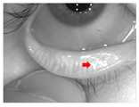
눈꺼풀의 마이봄샘을 촬영하기 위해, 종래에는 눈꺼풀의 피부 쪽에 광원을 대고 눈꺼풀을 뒤집어, 피부와 마이봄샘을 통과한 빛의 영상을 촬영(transillumination)하였다. 그러나 이와 같은 종래의 검사 방식은 광원이 피부에 접촉하기 때문에 열감, 눈부심 등이 발생되어, 피검사자 혹은 환자에게 불편을 초래하였다. 또한, 도 7의 사진에서 보여지는 바와 같이, 종래에는 마이봄샘 촬영 시 반사광(화살표로 표시됨)이 마이봄샘 촬영을 방해하여 깨끗한 마이봄샘 영상 혹은 이미지를 얻기 어려웠으며, 이로 인해, 마이봄샘 기능장애에 대한 정확한 진단이 어려운 문제가 있었다.In order to photograph the myal spring of the eyelid, a light source was placed on the skin side of the eyelid and the eyelid was turned upside down, and the image of the light passing through the skin and my spring was photographed (transillumination). However, in the conventional inspection method as described above, since the light source comes into contact with the skin, heat, glare and the like are generated, which causes inconvenience to the examinee or the patient. As shown in the photograph of FIG. 7, conventionally, reflected light (indicated by an arrow) when photographing My Spring Harbor interferes with MySpace imaging, making it difficult to obtain a clean MySpace image or an image, There was a problem that accurate diagnosis was difficult.
본 발명은 상술한 바와 같은 종래기술의 문제점을 해결하기 위해 안출된 것으로서, 본 발명의 목적은 피검사안에 대한 마이봄샘 촬영 시 결막표면으로부터 반사되는 과도한 반사광을 제거할 수 있고, 이를 통해, 깨끗한 마이봄샘 이미지 혹은 영상을 얻을 수 있는 적외선 마이봄샘 촬영장치를 제공하는 것이다.SUMMARY OF THE INVENTION The present invention has been made to solve the above problems of the prior art, and it is an object of the present invention to provide a method and apparatus for removing excess reflected light reflected from a conjunctiva And to provide an infrared myalobasamic imaging device capable of obtaining a spring normal image or an image.
이를 위해, 본 발명은, 피검사안의 마이봄샘을 촬영하는 촬영부; 상기 촬영부에 인접 배치되어 상기 마이봄샘을 향해 적외선을 조사하는 제1 광원 및 제2 광원을 포함하는 광원부; 상기 촬영부 및 상기 광원부를 동작시키는 제어부; 상기 제1 광원 동작 시 상기 촬영부에서 촬영된 제1 영상과 상기 제2 광원 동작 시 상기 촬영부에서 촬영된 제2 영상을 합성한 마이보그래피 영상을 생성 및 출력하는 영상 처리부; 및 상기 마이봄샘과 상기 촬영부 사이에 배치되어 상기 마이봄샘을 향해 적외선 조사 시 결막표면에서 반사되는 과도한 반사광을 제거하는 편광 필터부를 포함하는 적외선 마이봄샘 촬영장치를 제공한다.To this end, the present invention provides a photographing apparatus comprising: A light source unit including a first light source and a second light source disposed adjacent to the photographing unit and configured to irradiate infrared rays toward the My spring spring; A control unit for operating the photographing unit and the light source unit; An image processor for generating and outputting a first mvographed image obtained by combining a first image photographed by the photographing unit and a second image photographed by the photographing unit during the second light source operation during the first light source operation; And a polarized light filter unit disposed between the my spring and the photographing unit to remove excess reflected light reflected from the surface of the conjunctiva when irradiated with infrared rays toward the My myo spring.
여기서, 상기 촬영부는 전방면에 적외선 통과 필터가 장착되어 있는 카메라일 수 있다.Here, the photographing unit may be a camera equipped with an infrared ray passing filter on the front side.
상기 제1 광원 및 상기 제2 광원은 상기 촬영부를 기준으로, 상기 촬영부의 일측 및 타측에 각각 배치될 수 있다.The first light source and the second light source may be respectively disposed on one side and the other side of the photographing unit with reference to the photographing unit.
또한, 상기 광원부는 상기 촬영부의 둘레를 따라 배치되는 복수 개의 광원을 포함하되, 상기 제1 광원 및 상기 제2 광원은 상기 복수 개의 광원 중 상기 제어부에 의해 선택되고, 상기 촬영부를 기준으로, 상기 촬영부의 일측 및 타측에 각각 배치되는 광원으로 정의될 수 있다.The light source unit may include a plurality of light sources disposed along the periphery of the photographing unit, wherein the first light source and the second light source are selected by the control unit among the plurality of light sources, Can be defined as a light source disposed on one side and the other side, respectively.
상기 제어부는 상기 제1 광원이 동작되는 경우에는 상기 제2 광원이 동작되지 않고, 상기 제2 광원이 동작되는 경우에는 상기 제1 광원이 동작되지 않도록 제어할 수 있다.The controller may control the second light source not to operate when the first light source is operated and the first light source to not operate when the second light source is operated.
상기 편광 필터부는 선편광 필터를 포함할 수 있다.The polarizing filter unit may include a linearly polarized light filter.
이때, 상기 편광 필터부는 4분의1 파장판을 더 포함할 수 있다. 즉, 원형편광 필터도 가능하다.At this time, the polarization filter unit may further include a quarter wave plate. That is, a circularly polarized light filter is also possible.
상기 선편광 필터는 TAC(triacetyl cellulose) 필터 및 PVA(polyvinyl alcohol) 필터를 포함할 수 있다.The linearly polarized light filter may include a triacetyl cellulose (TAC) filter and a polyvinyl alcohol (PVA) filter.
또한, 선편광 필터는 상기 TAC 필터, 상기 PVA 필터 및 상기 TAC 필터의 적층으로 이루어질 수 있다.In addition, the linearly polarized light filter may be formed by laminating the TAC filter, the PVA filter, and the TAC filter.
상기 마이봄샘에 대한 상기 촬영부의 위치 및 상기 광원부의 적외선 조사 각도와 조사 범위를 조절하는 이동부를 더 포함할 수 있다.And a moving unit for adjusting the position of the photographing unit with respect to the my spring and the irradiation angle and irradiation range of the light source unit.
본 발명에 따르면, 마이봄샘을 촬영하는 카메라 렌즈의 전방에 편광필터를 배치함으로써, 피검사안에 대한 마이봄샘 촬영 시 결막표면에서 반사되는 과도한 반사되는 반사광을 제거할 수 있고, 이를 통해, 깨끗한 마이봄샘 이미지 혹은 영상을 얻을 수 있다.According to the present invention, by arranging the polarizing filter in front of the camera lens for photographing the my spring spring, it is possible to remove excess reflected light reflected from the conjunctiva surface at the time of photographing the myaloscope to the subject, Images or images can be obtained.
즉, 본 발명에 따르면, 결막표면으로부터 반사되는 반사광 제거를 통해, 적외선 마이봄샘 촬영장치의 신뢰성을 확보할 수 있고, 그 결과, 깨끗한 마이봄샘 이미지 혹은 영상을 획득할 수 있으며, 이를 통해, 마이봄샘 기능장애에 대한 정확한 진단을 가능하게 할 수 있다.That is, according to the present invention, it is possible to secure the reliability of the infrared mycolumbar apparatus by removing the reflected light reflected from the conjunctive surface, and as a result, it is possible to acquire a clean my spring image or image, It is possible to accurately diagnose a malfunction.
또한, 본 발명에 따르면, 카메라 렌즈의 측방에 설치되는 광원의 배치에 따라 편광필터의 축을 바꿈으로써 결막표면에서 반사되는 과도한 반사광을 최소한으로 할 수 있다.Further, according to the present invention, excessive light reflected from the conjunctive film surface can be minimized by changing the axis of the polarizing filter in accordance with the arrangement of the light source disposed on the side of the camera lens.
도 1은 본 발명의 일 실시 예에 따른 적외선 마이봄샘 촬영장치를 개략적으로 나타낸 도면이다.
도 2 및 도 3은 본 발명의 일 실시 예에 따른 적외선 마이봄샘 촬영장치의 광원 배치 구조를 개략적으로 나타낸 도면이다.
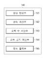
도 4는 도 1의 영상 처리부를 개략적으로 나타낸 블럭도이다.
도 5는 도 4의 영상 처리부에 의해 제1 영상과 제2 영상이 합성된 마이보그래피 이미지를 나타낸 도면이다.
도 6은 본 발명의 일 실시 예에 따른 적외선 마이봄샘 촬영장치의 편광 필터부를 설명하기 위한 도면이다.
도 7은 반사광이 발생된 피검사안을 촬영한 사진을 나타낸 도면이다.FIG. 1 is a schematic view of an apparatus for photographing an infrared myaloscope according to an embodiment of the present invention. Referring to FIG.
FIG. 2 and FIG. 3 are views schematically showing a light source arrangement structure of an infrared myosseam photographing apparatus according to an embodiment of the present invention.
4 is a block diagram schematically showing the image processing unit of FIG.
FIG. 5 is a view showing a myographic image in which a first image and a second image are synthesized by the image processing unit of FIG. 4. FIG.
6 is a view for explaining a polarizing filter unit of an infrared my myosin imaging apparatus according to an embodiment of the present invention.
FIG. 7 is a photograph showing a photograph of a subject subject to which reflected light is generated. FIG.
본 명세서에서 사용되는 용어에 대해 간략히 설명하고, 본 발명에 대해 구체적으로 설명하기로 한다.The terms used in this specification will be briefly described and the present invention will be described in detail.
본 발명에서 사용되는 용어는 본 발명에서의 기능을 고려하면서 가능한 현재 널리 사용되는 일반적인 용어들을 선택하였으나, 이는 당 분야에 종사하는 기술자의 의도 또는 판례, 새로운 기술의 출현 등에 따라 달라질 수 있다. 또한, 측정한 경우는 출원인이 임의로 선정한 용어도 있으며, 이 경우 해당되는 발명의 설명 부분에서 상세히 그 의미를 기재할 것이다. 따라서, 본 발명에서 사용되는 용어는 단순한 용어의 명칭이 아닌, 그 용어가 가지는 의미와 본 발명의 전반에 걸친 내용을 토대로 정의되어야 한다.While the present invention has been described in connection with what is presently considered to be the most practical and preferred embodiment, it is to be understood that the invention is not limited to the disclosed embodiments. Also, in the case of measurement, there is a term arbitrarily selected by the applicant, and in this case, the meaning will be described in detail in the description part of the corresponding invention. Therefore, the term used in the present invention should be defined based on the meaning of the term, not on the name of a simple term, but on the entire contents of the present invention.
명세서 전체에서 어떤 부분이 어떤 구성요소를 "포함"한다고 할 때, 이는 특별히 반대되는 기재가 없는 한 다른 구성요소를 제어하는 것이 아니라 다른 구성요소를 더 포함할 수 있음을 의미한다. 또한, 명세서에 기재된 "...부" 등의 용어는 적어도 하나의 기능이나 동작을 처리하는 단위를 의미하며, 이는 하드웨어 또는 소프트웨어로 구현되거나 하드웨어와 소프트웨어의 결합으로 구현될 수 있다.When an element is referred to as "including" an element throughout the specification, it is to be understood that the element may include other elements, rather than controlling other elements, unless otherwise specifically stated. Furthermore, the term "part" or the like described in the specification means a unit for processing at least one function or operation, which may be implemented by hardware or software, or a combination of hardware and software.
아래에서는 첨부한 도면을 참고하여 본 발명의 실시 예에 대하여 본 발명이 속하는 기술 분야에서 통상의 지식을 가진 자가 용이하게 실시할 수 있도록 상세히 설명한다. 그러나 본 발명은 여러 가지 상이한 형태로 구현될 수 있으며 여기에서 설명하는 실시 예에 한정되지 않는다. 그리고 도면에서 본 발명을 명확하게 설명하기 위해서 설명과 관계없는 부분은 생략하였으며, 명세서 전체를 통하여 유사한 부분에 대해서는 유사한 도면 부호를 붙였다.Hereinafter, embodiments of the present invention will be described in detail with reference to the accompanying drawings so that those skilled in the art can easily carry out the present invention. The present invention may, however, be embodied in many different forms and should not be construed as limited to the embodiments set forth herein. In order to clearly illustrate the present invention, parts not related to the description are omitted, and similar parts are denoted by like reference characters throughout the specification.
도 1은 본 발명의 일 실시 예에 따른 적외선 마이봄샘 촬영장치를 개략적으로 나타낸 도면이이고, 도 2 및 도 3은 본 발명의 일 실시 예에 따른 적외선 마이봄샘 촬영장치의 광원 배치 구조를 개략적으로 나타낸 도면이며, 도 4는 도 1의 영상 처리부를 개략적으로 나타낸 블럭도이고, 도 5는 도 4의 영상 처리부에 의해 제1 영상과 제2 영상이 합성된 마이보그래피 이미지를 나타낸 도면이며, 도 6은 본 발명의 일 실시 예에 따른 적외선 마이봄샘 촬영장치의 편광 필터부를 설명하기 위한 도면이다.FIG. 1 is a schematic view of an infrared myaloscope apparatus according to an embodiment of the present invention. FIGS. 2 and 3 schematically show a light source arrangement structure of an infrared myalobraam apparatus according to an embodiment of the present invention. FIG. 4 is a block diagram schematically showing the image processing unit of FIG. 1, FIG. 5 is a view showing a myographic image in which a first image and a second image are synthesized by the image processing unit of FIG. 4, 6 is a view for explaining a polarization filter unit of an infrared my myosin imaging apparatus according to an embodiment of the present invention.
도 1에 도시한 바와 같이, 본 발명의 일 실시 예에 따른 적외선 마이봄샘 촬영장치(100)는 피검사안의 눈꺼풀에 위치된 분비샘인 마이봄샘을 촬영하기 위한 장치로, 촬영부(110), 광원부(120), 제어부(130), 영상 처리부(140), 편광 필터부(150)를 포함하여 형성된다.As shown in FIG. 1, an
촬영부(110)는 적외선 마이봄샘 촬영장치(100)에서 실제, 피검사안의 마이봄샘에 대한 촬영이 이루어지는 부분이다. 본 발명의 일 실시 예에 따른 촬영부(110)는 전방면, 즉, 마이봄샘과 마주하는 면에 적외선 통과 필터(114)가 장착되어 있는 카메라(111)로 구비될 수 있다. 이때, 카메라(111)는 렌즈(112)와 이미지 센서(113)를 포함할 수 있다. 이미지 센서(113)는 렌즈(112)를 통해 조사된 빛으로부터 이미지를 생성한다. 예를 들어, 이미지 센서(113)는 상보성 금속 산화물 반도체를 이용하는 CMOS(complementary metal oxide semiconductor) 또는 Charge coupled device (CCD)로 이루어질 수 있다.The photographing
이러한 촬영부(110)는 제어부(130)에 의해 동작된다. 또한, 촬영부(110)는 광원부(120)에서 마이봄샘을 향해 적외선을 조사하는 동안 마이봄샘에 대한 이미지를 취득 혹은 마이봄샘에 대한 영상을 촬영한다. 이때, 본 발명의 일 실시 예에서는 촬영부(110)에 의한 마이봄샘 촬영 시 결막표면으로부터 반사되는 반사광이 마이봄샘과 촬영부(110) 사이에 배치되는 편광 필터부(150)에 의해 제거되는데 이에 대해서는 하기에서 보다 상세히 설명하기로 한다.The photographing
한편, 촬영부(110)에 의해 촬영된 영상들은 영상 처리부(140)에 전송되어 마이보그래피 이미지 혹은 영상으로 생성된다.On the other hand, the images photographed by the photographing
광원부(120)는 촬영부(110)의 적외선 영상 촬영이 가능하도록, 마이봄샘을 향해 적외선을 조사하는 장치이다. 이러한 광원부(120)는 IR LED로 이루어질 수 있다. 하지만, 이는 일례일 뿐, 광원부(120)는 IR LED 외에도 다양한 IR 광원으로 이루어질 수 있다.The
본 발명의 일 실시 예에 따른 광원부(120)는 촬영부(110), 보다 상세하게는 렌즈(112)의 측방에 인접 배치된다. 도 1 내지 도 3에 도시한 바와 같이, 광원부(120)는 렌즈(112)를 중심으로 하는 카메라(111)의 날개 프레임에 설치될 수 있다. 본 발명의 일 실시 예에 따른 광원부(120)는 제1 광원(121) 및 제2 광원(122)을 포함한다. 이때, 제1 광원(121) 및 제2 광원(122)은 각각, 적어도 하나의 광원으로 이루어질 수 있다. 또한, 제1 광원(121) 및 제2 광원(122)은 촬영부(110)의 렌즈(112)를 기준으로, 렌즈(112)의 일측 및 타측에 각각 배치될 수 있다. 즉, 도 2에 도시한 바와 같이, 제1 광원(121)은 렌즈(112)의 좌측에 배치되고, 제2 광원(122)은 렌즈(112)의 우측에 배치될 수 있다. 또한, 도 3에 도시한 바와 같이, 제1 광원(121)은 렌즈(112)의 상측에 배치되고, 제2 광원(122)은 렌즈(112)의 하측에 배치될 수 있다. 여기서, 제1 광원(121)과 제2 광원(122)을 렌즈(112)의 좌우측 또는 상하측에 배치시키는 이유는 결막표면으로부터 반사되는 빛, 즉, 반사광을 편광시켜, 편광 필터부(150)를 통해 이 반사광을 제거하기 위함인데, 이에 대해서는 하기에서 보다 상세히 설명하기로 한다.The
한편, 렌즈(112)의 좌우측 또는 상하측에 각각 배치되는 제1 광원(121)과 제2 광원(122)은 30㎜ 내지 150㎜ 간격으로 서로 이격, 바람직하게는 120㎜ 간격으로 서로 이격될 수 있다. 또한, 제1 광원(121)과 제2 광원(122)은 렌즈(122)와 마이봄샘이 이루는 라인을 기준으로 할 때, 30도 내지 60도 각도로 마이봄샘을 향해 적외선을 조사하도록 배치될 수 있다.On the other hand, the first
이러한 제1 광원(121) 및 제2 광원(122)은 제어부(130)에 의해 순차적으로 동작될 수 있다. 즉, 제1 광원(121)이 동작되는 경우에는 제2 광원(122)이 동작되지 않고, 제2 광원(122)이 동작되는 경우에는 제1 광원(121)이 동작되지 않도록 제어될 수 있다.The first
한편, 광원부(120)는 촬영부(110)의 둘레, 보다 상세하게는 렌즈(112)의 둘레를 따라 배치되는 복수 개의 광원을 포함할 수 있다. 예를 들어, 광원부(120)는 도 2의 제1 광원(121)과 제2 광원(122) 및 도 3의 제1 광원(121)과 제2 광원(122)이 모두 렌즈(112)의 좌우측 및 상하측에 배치된 구조로도 이루어질 수 있다. 여기서, 결막표면으로부터 반사되는 반사광을 편광시키기 위해서는 렌즈(112)의 좌우측 또는 렌즈(112)의 상하측에 배치된 광원만이 필요하므로, 렌즈(112)의 둘레를 따라 복수 개의 광원이 배치된 구조에서는 제어부(130)에 의해 복수 개의 광원 중 제1 광원(121)과 제2 광원(122)이 선택될 수 있다. 즉, 렌즈(112)의 둘레를 따라 복수 개의 광원이 배치된 구조에서, 제1 광원(121)과 제2 광원(122)은 복수 개의 광원 중 렌즈(112)의 일측 및 타측에 각각 배치되는 광원으로 정의될 수 있다. 이와 같이, 렌즈(112)의 둘레를 따라 복수 개의 광원이 배치되고, 이 중에서 제1 광원(121)과 제2 광원(122)이 선택되면, 제1 광원(121)과 제2 광원(122)을 좌우측 또는 상하측으로 배치하기 위한 촬영부(110)의 회전 동작이나 광원부(120)가 설치되어 있는 카메라(111)의 날개 프레임의 교체와 같은 부수적인 제어를 생략할 수 있어, 적외선 마이봄샘 촬영장치(100)를 보다 효율적으로 운용할 수 있게 된다.Meanwhile, the
제어부(130)는 촬영부(110)와 광원부(120)의 동작을 제어한다. 즉, 제어부(130)는 촬영부(110)의 마이봄샘 촬영을 제어하고, 광원부(120)의 적외선 조사를 제어한다. 예를 들어, 제어부(130)는 제1 광원(121)과 제2 광원(122)의 동작을 위한 시간 정보를 설정한 다음, 촬영부(110)를 동작시킨 후 시간 정보에 따라, 제1 광원(121)과 제2 광원(122)을 순차적으로 동작시킨다. 이때, 제어부(130)는 제1 광원(121)이 동작되는 경우에는 제2 광원(122)이 동작되지 않도록 제어하고, 제2 광원(122)이 동작되는 경우에는 제1 광원(121)이 동작되지 않도록 제어할 수 있다. 또한, 제어부(130)는, 광원부(120)가 렌즈(112)의 둘레를 따라 배치되는 복수 개의 광원으로 이루어진 경우, 복수 개의 광원 중 제1 광원(121)과 제2 광원(122)을 선택할 수 있다.The
영상 처리부(140)는 제1 광원(121) 동작 시 촬영부(110)에서 촬영된 제1 영상과 제2 광원(122) 동작 시 촬영부(110)에서 촬영된 제2 영상을 합성한 마이보그래피 영상을 생성 및 출력한다. 이를 위해, 도 4에 도시한 바와 같이, 본 발명의 일 실시 예에 따른 영상 처리부(140)는 영상 합성부(141), 면적 계산부(142), 소핵 수 계산부(143), 소핵 크기 계산부(144) 및 정보 출력부(145)를 포함할 수 있다.The
영상 합성부(141)는 제1 광원(121) 동작 시 촬영부(110)에서 촬영된 제1 영상과 제2 광원(122) 동작 시 촬영부(110)에서 촬영된 제2 영상을 자동으로 합성한 마이보그래피 영상을 생성한다. 즉, 영상 합성부(141)는 위아래 눈꺼풀의 윤곽을 기준으로 하여 제1 영상과 제2 영상을 자동으로 합성한 마이보그래피 영상을 생성한다.The
면적 계산부(142)는 영상 합성부(141)에 의해 생성된 마이보그래피 영상을 이용하여 복수 개의 마이봄샘으로 구성되는 마이봄샘 전체의 면적을 계산한다. 이때, 면적 계산부(142)는 미리 설정된 면적 산출 알고리즘에 의해, 도 5에 도시된 마이봄샘(M)만의 면적을 구할 수도 있고, 마이봄샘(M)이 포함된 윤곽선의 전체 면적 대비 마이봄샘(M)이 차지하는 면적의 비율도 산출할 수 있다. 이를 보다 상세히 설명하면, 면적 계산부(142)는 면적 산출 알고리즘을 이용하여 영상 합성부(141)에 의해 생성된 마이보그래피 영상에서의 길이와 실제 길이의 비를 이용하여 마이봄샘의 길이 및 면적을 산출한다. 여기서, 상기 실제 길이는 사전에 실제로 길이 측정 수단으로 측정된 정보이다. 한편, 마이봄샘에 소핵이 있는 부위는 소핵이 없는 부위에 비해 밝으므로, 면적 계산부(142)는 면적 산출 알고리즘을 통해 밝기의 한계값을 설정함으로써, 자동으로 소핵들을 인식하고, 각각의 면적을 산출할 수 있다. 그리고 면적 계산부(142)는 이와 같은 방식으로 산출된 각각의 면적을 더하여 마이봄샘의 전체 면적을 산출하게 된다.The
소핵 수 계산부(143)는 영상 합성부(141)에 의해 생성된 마이보그래피 영상을 이용하여 마이봄샘에 달려있는 소핵(acinus)의 수를 계산한다. 즉, 소핵 수 계산부(143)는 마이보그래피 영상에서 1개의 마이봄샘에 달려있는 소핵의 수를 자동으로 계산한다.The
소핵 크기 계산부(144)는 영상 합성부(141)에 의해 생성된 마이보그래피 영상을 이용하여 소핵의 크기에 대한 평균 및 표준편차를 계산한다.The
정보 출력부(145)는 영상 합성부(141)에 의해 생성된 마이보그래피 영상, 면적 계산부(142)에 의해 계산된 마이봄샘 전체의 면적, 소핵 수 계산부(143)에 의해 계산된 소핵의 수 및 소핵 크기 계산부(144)에 의해 계산된 소핵의 크기에 대한 평균 및 표준편차에 관한 정보를 출력한다. 이러한 정보 출력부(145)는 사용자에 의해 터치 입력이 가능하도록 터치 스크린으로 구현될 수 있고, 이때, 터치 스크린에 채용되는 디스플레이 패널은 LCD, LED, OLED 등으로 이루어질 수 있다.The
편광 필터부(150)는 마이봄샘과 촬영부(110) 사이에 배치된다. 구체적으로, 편광 필터부(150)는 카메라(111)의 렌즈(112) 전방에 배치되는 적외선 통과 필터(114) 상에 적층되는 형태로 구비될 수 있다. 이러한 편광 필터부(150)는 광원부(120)에서 마이봄샘을 향해 적외선을 조사하는 경우 결막표면으로부터 반사되는 반사광을 제거하는 역할을 한다.The polarized
도 6에 도시한 바와 같이, 편광 필터부(150)는 선편광 필터(152)를 포함하되, 4분의1 파장판(quarter-wave plate)(153)을 더 포함할 수 있다. 즉, 원형편광필터도 가능하다As shown in FIG. 6, the
이때, 선편광 필터(152)는 TAC(triacetyl cellulose) 필터 및 PVA(polyvinyl alcohol) 필터를 포함할 수 있다. 예를 들어, 선편광 필터(152)는 TAC 필터, PVA 필터 및 TAC 필터의 적층으로 이루어질 수 있다. 여기서, PVA 필터는 광을 편광시키는 역할을 하는 필터로, 고분자 물질인 폴리비닐알콜에 2색성 색소를 흡착시켜 형성할 수 있다. 그리고 이러한 PVA 필터의 양면에 배치되는 TAC 필터는 PVA 필터를 지지하는 역할을 하게 된다.At this time, the
한편, 4분의1 파장판(153)은 서로 수직인 방향으로 진동하는 선평관의 사이에 1/4 파장의 광로차를 발생시키는 복굴절판으로서, 빛이 입사되는 방향을 기준으로 선편광 필터(152)의 뒤편에 적층 배치된다. 4분의1 파장판(153)에 주축 방위와 45도 방위를 가지는 선편광을 넣으면 투과광은 원형편광이 된다.On the other hand, the
비편광된 빛이 입사하면, 이 빛은 선편광 필터(152)를 구성하는 PVA 필터에 의해 선편광으로 변하고, 4분의1 파장판(153)에 의해 원형편광이 된다.When the unpolarized light is incident, the light is converted into linearly polarized light by the PVA filter constituting the
한편, 본 발명의 일 실시 예에 따른 편광 필터부(150)는 선편광 필터(152)만으로도 이루어질 수 있다. 이를 위해서는 도 2 및 도 3에 도시한 바와 같이, 제1 광원(121)과 제2 광원(122)은 렌즈(112)의 좌우측 또는 상하측에 배치되는 것이 요구된다. 예를 들어, 도 2와 같이, 제1 광원(121)과 제2 광원(122)이 렌즈(112)의 좌우측에 배치되면, 이들의 적외선 조사 시 결막표면에서 반사된 빛은 수직방향으로 편광된다. 따라서, 편광 필터부(150)를 투과축이 수평방향인 선편광 필터(152)로 구비하면, 반사광을 제거할 수 있게 된다. 또한, 도 3과 같이, 제1 광원(121)과 제2 광원(122)이 렌즈(112)의 상하측에 배치되면, 이들의 적외선 조사 시 결막표면으로부터 반사된 빛은 수평방향으로 편광된다. 따라서, 편광 필터부(150)를 투과축이 수직방향인 선편광 필터(152)로 구비하면, 반사광을 제거할 수 있다.Meanwhile, the
한편, 편광 필터부(150)로서 선편광 필터(152)와 4분의1 파장판(153)이 결합된 원형편광필터를 사용할 수도 있다. 이때 선편광 필터(152)는 피검사안쪽으로, 4분의1 파장판(153)는 카메라쪽으로 향하도록 배치된다. 위의 예처럼 제1 광원(121)과 제2 광원(122)이 렌즈(112)의 좌우측에 배치되면 선편광 필터(152)의 투과축을 수평방향으로 하고, 제1 광원(121)과 제2 광원(122)이 렌즈(112)의 상하측에 배치되면 선편광 필터(152)의 투과축을 수직방향으로 하여 반사광을 제거할 수 있다.Alternatively, a circular polarization filter in which the
이와 같이, 마이봄샘과 촬영부(110) 사이, 즉, 카메라(111)의 렌즈(112) 전방에 편광 필터부(150)를 배치하면, 피검사안에 대한 마이봄샘 촬영 시 결막표면으로부터 반사되는 반사광을 제거할 수 있고, 이를 통해, 깨끗한 마이봄샘의 이미지 혹은 영상을 얻을 수 있어, 적외선 마이봄샘 촬영장치(100)의 신뢰성을 확보함과 아울러, 마이봄샘 기능장애에 대한 정확한 진단을 내릴 수 있게 된다.As described above, when the
한편, 본 발명의 일 실시 예에 따른 적외선 마이봄샘 촬영장치(100)는 이동부(160)를 더 포함할 수 있다. 이동부(160)는 제어부(130)의 명령에 따라, 마이봄샘에 대한 촬영부(110)의 위치를 조절한다. 이를 위해, 이동부(160)는 촬영부(110)를 패닝 또는 틸팅 시키는 구동 모터를 포함할 수 있다. 여기서, 패닝은 촬영부(110)의 좌우 방향으로의 회전을, 틸팅은 촬영부(110)의 상하 방향으로의 회전을 의미한다. 또한, 이동부(160)는 광원부(120)를 전후, 좌우 및 상하로 이동시킬 수 있으며, 이를 통해, 광원부(120)의 마이봄샘에 대한 적외선 조사 각도나 적외선 조사 범위를 조절할 수 있게 된다.Meanwhile, the infrared
이하, 본 발명의 일 실시 예에 따른 적외선 마이봄샘 촬영장치의 동작에 대해 설명하기로 한다. 이때, 각 구성요소들의 도면부호는 도 1 내지 도 6을 참조한다.Hereinafter, an operation of the infrared mycolumbar radiography apparatus according to an embodiment of the present invention will be described. Here, reference numerals of the respective components refer to Figs. 1 to 6.
먼저, 사용자가 촬영 버튼(미도시)을 누르면, 제어부(130)에 의해 제1 광원(121)만 점등된 상태에서 촬영부(110)가 마이봄샘을 촬영하여, 제1 영상을 획득한다. 그 다음, 제어부(130)에 의해 제1 광원(121)은 꺼지고, 제2 광원(122)만 점등된 상태에서 촬영부(110)가 마이봄샘을 촬영하여, 제2 영상을 획득한다. 이때, 촬영부(110)에 의한 마이봄샘 촬영 시 촬영부(110)의 전방에 배치되어 있는 편광 필터부(150)에 의해 결막표면으로부터 반사되는 반사광이 제거되어, 깨끗하고 선명한 제1 영상 및 제2 영상을 얻을 수 있게 된다.First, when the user presses a photographing button (not shown), the photographing
그 다음, 촬영부(110)의 마이봄샘 촬영을 통해 획득한 제1 영상 및 제2 영상은 영상 처리부(140)에 의해 자동으로 합성되어 마이보그래피 영상으로 생성 및 출력된다. 즉, 상기의 제1 영상 및 제2 영상은 영상 합성부(141)에 의해 합성되어 마이보그래피 영상으로 생성되고, 이 마이보그래피 영상은 면적 계산부(142)에 의해 복수 개의 마이봄샘으로 구성되는 마이봄샘 전체 면적 계산에 이용된다. 또한, 영상 합성부(141)에 의해 생성된 마이보그래피 영상은 소핵 수 계산부(143)에 의해 마이봄샘에 달려있는 소핵 수 계산에도 이용된다. 그리고 영상 합성부(141)에 의해 생성된 마이보그래피 영상은 소핵 크기 계산부(144)에 의해 소핵의 크기에 대한 평균 및 표준편차를 계산하는데도 이용된다.Then, the first image and the second image acquired through the microphotographing of the photographing
마지막으로, 영상 합성부(141)에 의해 생성된 마이보그래피 영상, 면적 계산부(142)에 의해 계산된 마이봄샘 전체의 면적, 소핵 수 계산부(143)에 의해 계산된 소핵의 수 및, 소핵 크기 계산부(144)에 의해 계산된 소핵의 크기에 대한 평균 및 표준편차에 관한 정보는 정보 출력부(145)를 통해 출력된다. 이때, 상기와 같이, 영상 합성부(141), 면적 계산부(142), 소핵 수 계산부(143), 소핵 크기 계산부(144) 및 정보 출력부(145)를 통해 구현되는 영상 처리부(140)의 기능은 컴퓨터가 읽을 수 있는 기록매체에 컴퓨터가 읽을 수 있는 코드로 구현될 수 있다. 여기서, 컴퓨터가 읽을 수 있는 기록매체는 컴퓨터에 의해 읽혀지는 데이터가 저장되는 모든 기록장치를 포함한다. 컴퓨터가 읽을 수 있는 기록매체의 예로는 ROM, RAM, CD-ROM, 자기 테이프, 광 데이터 저장장치 등이 있으며, 예컨대, 인터넷을 통한 전송과 같은 캐리어 웨이브(carrier wave) 형태로 구현되는 것도 포함한다. 또한, 컴퓨터로 읽을 수 있는 기록매체는 네트워크로 연결된 컴퓨터 시스템에서 분산되어 분산방식으로 컴퓨터가 읽을 수 있는 코드가 저장되고 실행되는 것을 포함한다.Finally, the micrograph image generated by the
이상에서 설명한 것은 본 발명에 의한 적외선 마이봄샘 촬영장치를 실시하기 위한 하나의 실시 예에 불과한 것으로서, 본 발명은 상기 실시 예에 한정되지 않고, 이하의 특허청구범위에서 청구하는 바와 같이 본 발명의 요지를 벗어남이 없이 당해 발명이 속하는 분야에서 통상의 지식을 가진 자라면 누구든지 다양한 변경 실시가 가능한 범위까지 본 발명의 기술적 정신이 있다고 할 것이다.The present invention is not limited to the above-described embodiment, but may be embodied in the spirit and scope of the present invention as claimed in the following claims. It will be understood by those of ordinary skill in the art that various changes in form and details may be made therein without departing from the spirit and scope of the invention.
100: 적외선 마이봄샘 촬영장치
110: 촬영부111: 카메라
112: 렌즈113: 이미지 센서
114: 적외선 통과 필터120: 광원부
121: 제1 광원122: 제2 광원
130: 제어부140: 영상 처리부
141: 영상 합성부142: 면적 계산부
143: 소핵 수 계산부144: 소핵 크기 계산부
145: 정보 출력부150: 편광 필터부
151: 원형편광 필터152: 선편광 필터
153: λ/4 위상차 필터160: 이동부100: Infrared myaloscope imaging device
110: photographing unit 111: camera
112: Lens 113: Image sensor
114: Infrared pass filter 120: Light source part
121: first light source 122: second light source
130: control unit 140:
141: image synthesis unit 142: area calculation unit
143: Micronucleus number calculation unit 144: Micronucleus size calculation unit
145: Information output unit 150: Polarization filter unit
151: circular polarized light filter 152: linear polarized light filter
153:? / 4 phase difference filter 160:
Claims (10)
Translated fromKorean상기 촬영부에 인접 배치되어 상기 마이봄샘을 향해 적외선을 조사하는 제1 광원 및 제2 광원을 포함하는 광원부;
상기 촬영부 및 상기 광원부를 동작시키는 제어부;
상기 제1 광원 동작 시 상기 촬영부에서 촬영된 제1 영상과 상기 제2 광원 동작 시 상기 촬영부에서 촬영된 제2 영상을 합성한 마이보그래피 영상을 생성 및 출력하는 영상 처리부; 및
상기 마이봄샘과 상기 촬영부 사이에 배치되어 상기 마이봄샘을 향해 적외선 조사 시 결막표면으로부터 반사되는 반사광을 제거하는 편광 필터부;
를 포함하는 적외선 마이봄샘 촬영장치.
A photographing section for photographing the my spring spring of the subject;
A light source unit including a first light source and a second light source disposed adjacent to the photographing unit and configured to irradiate infrared rays toward the My spring spring;
A control unit for operating the photographing unit and the light source unit;
An image processor for generating and outputting a first mvographed image obtained by combining a first image photographed by the photographing unit and a second image photographed by the photographing unit during the second light source operation during the first light source operation; And
A polarized light filter unit disposed between the My spring spring and the photographing unit to remove reflected light reflected from the conjunctiva surface when irradiated with infrared rays toward the My spring spring;
And an infrared microsampler imaging device.
상기 촬영부는 전방면에 적외선 통과 필터가 장착되어 있는 카메라인 적외선 마이봄샘 촬영장치.
The method according to claim 1,
Wherein the photographing unit is a camera having a front infrared ray filter mounted on the front surface thereof.
상기 제1 광원 및 상기 제2 광원은 상기 촬영부를 기준으로, 상기 촬영부의 일측 및 타측에 각각 배치되는 적외선 마이봄샘 촬영장치.
The method according to claim 1,
Wherein the first light source and the second light source are respectively disposed on one side and the other side of the photographing section with reference to the photographing section.
상기 광원부는 상기 촬영부의 둘레를 따라 배치되는 복수 개의 광원을 포함하되,
상기 제1 광원 및 상기 제2 광원은 상기 복수 개의 광원 중 상기 제어부에 의해 선택되고, 상기 촬영부를 기준으로, 상기 촬영부의 일측 및 타측에 각각 배치되는 광원으로 정의되는 적외선 마이봄샘 촬영장치.
The method according to claim 1,
Wherein the light source unit includes a plurality of light sources disposed along the periphery of the photographing unit,
Wherein the first light source and the second light source are defined by a light source selected by the control unit among the plurality of light sources and disposed on one side and the other side of the photographing unit with respect to the photographing unit.
상기 제어부는 상기 제1 광원이 동작되는 경우에는 상기 제2 광원이 동작되지 않고, 상기 제2 광원이 동작되는 경우에는 상기 제1 광원이 동작되지 않도록 제어하는 적외선 마이봄샘 촬영장치.
The method according to claim 1,
Wherein the controller controls the second light source not to operate when the first light source is operated and controls the first light source not to operate when the second light source is operated.
상기 편광 필터부는 선편광 필터를 포함하는 적외선 마이봄샘 촬영장치.
The method according to claim 1,
Wherein the polarizing filter unit comprises a linearly polarized light filter.
상기 편광 필터부는 4분의1 파장판을 더 포함하는 것을 특징으로 하는, 적외선 마이봄샘 촬영장치.
The method according to claim 6,
Wherein the polarizing filter unit further comprises a quarter wave plate.
상기 선편광 필터는 TAC(triacetyl cellulose) 필터 및 PVA(polyvinyl alcohol) 필터를 포함하는 적외선 마이봄샘 촬영장치.
The method according to claim 6,
Wherein the linearly polarized light filter comprises a triacetyl cellulose (TAC) filter and a polyvinyl alcohol (PVA) filter.
상기 선편광 필터는,
상기 TAC 필터, 상기 PVA 필터 및 상기 TAC 필터의 적층으로 이루어지는 적외선 마이봄샘 촬영장치.
9. The method of claim 8,
In the linearly polarized light filter,
Wherein the TAC filter, the PVA filter, and the TAC filter are laminated.
상기 마이봄샘에 대한 상기 촬영부의 위치 및 상기 광원부의 적외선 조사 각도와 조사 범위를 조절하는 이동부를 더 포함하는 적외선 마이봄샘 촬영장치.The method according to claim 1,
Further comprising a moving unit for adjusting a position of the photographing unit with respect to the my spring and an irradiation angle and an irradiation range of the light source unit.
Priority Applications (1)
| Application Number | Priority Date | Filing Date | Title |
|---|---|---|---|
| KR1020160093665AKR101755630B1 (en) | 2016-07-22 | 2016-07-22 | Meibomian photographing gland device using infrared ray |
Applications Claiming Priority (1)
| Application Number | Priority Date | Filing Date | Title |
|---|---|---|---|
| KR1020160093665AKR101755630B1 (en) | 2016-07-22 | 2016-07-22 | Meibomian photographing gland device using infrared ray |
Publications (1)
| Publication Number | Publication Date |
|---|---|
| KR101755630B1true KR101755630B1 (en) | 2017-07-07 |
Family
ID=59353708
Family Applications (1)
| Application Number | Title | Priority Date | Filing Date |
|---|---|---|---|
| KR1020160093665AExpired - Fee RelatedKR101755630B1 (en) | 2016-07-22 | 2016-07-22 | Meibomian photographing gland device using infrared ray |
Country Status (1)
| Country | Link |
|---|---|
| KR (1) | KR101755630B1 (en) |
Cited By (8)
| Publication number | Priority date | Publication date | Assignee | Title |
|---|---|---|---|---|
| US9795290B2 (en) | 2013-11-15 | 2017-10-24 | Tearscience, Inc. | Ocular tear film peak detection and stabilization detection systems and methods for determining tear film layer characteristics |
| US9888839B2 (en) | 2009-04-01 | 2018-02-13 | Tearscience, Inc. | Methods and apparatuses for determining contact lens intolerance in contact lens wearer patients based on dry eye tear film characteristic analysis and dry eye symptoms |
| US9993151B2 (en) | 2012-12-21 | 2018-06-12 | Tearscience, Inc. | Full-eye illumination ocular surface imaging of an ocular tear film for determining tear film thickness and/or providing ocular topography |
| US9999346B2 (en) | 2009-04-01 | 2018-06-19 | Tearscience, Inc. | Background reduction apparatuses and methods of ocular surface interferometry (OSI) employing polarization for imaging, processing, and/or displaying an ocular tear film |
| US10004396B2 (en) | 2009-04-01 | 2018-06-26 | Tearscience, Inc. | Ocular surface interferometry (OSI) devices and systems for imaging, processing, and/or displaying an ocular tear film |
| US10278587B2 (en) | 2013-05-03 | 2019-05-07 | Tearscience, Inc. | Eyelid illumination systems and method for imaging meibomian glands for meibomian gland analysis |
| KR102255497B1 (en)* | 2020-01-22 | 2021-05-24 | 주식회사 유엠아이옵틱스 | Photography Apparatus for Ophthalmology Disease |
| KR20210103276A (en)* | 2020-02-13 | 2021-08-23 | 주식회사 유엠아이옵틱스 | Portable meibomian photographing device |
Citations (3)
| Publication number | Priority date | Publication date | Assignee | Title |
|---|---|---|---|---|
| JP2009285447A (en) | 2007-08-16 | 2009-12-10 | Shiro Amano | Meibomian gland observing device |
| JP2012161427A (en) | 2011-02-04 | 2012-08-30 | Nidek Co Ltd | Ophthalmic photographing device |
| JP2012228309A (en) | 2011-04-25 | 2012-11-22 | Topcon Corp | Meibomian gland observation apparatus |
- 2016
- 2016-07-22KRKR1020160093665Apatent/KR101755630B1/ennot_activeExpired - Fee Related
Patent Citations (3)
| Publication number | Priority date | Publication date | Assignee | Title |
|---|---|---|---|---|
| JP2009285447A (en) | 2007-08-16 | 2009-12-10 | Shiro Amano | Meibomian gland observing device |
| JP2012161427A (en) | 2011-02-04 | 2012-08-30 | Nidek Co Ltd | Ophthalmic photographing device |
| JP2012228309A (en) | 2011-04-25 | 2012-11-22 | Topcon Corp | Meibomian gland observation apparatus |
Cited By (18)
| Publication number | Priority date | Publication date | Assignee | Title |
|---|---|---|---|---|
| US10582848B2 (en) | 2009-04-01 | 2020-03-10 | Tearscience, Inc. | Ocular surface interferometry (OSI) devices and systems for imaging, processing, and/or displaying an ocular tear film |
| US9888839B2 (en) | 2009-04-01 | 2018-02-13 | Tearscience, Inc. | Methods and apparatuses for determining contact lens intolerance in contact lens wearer patients based on dry eye tear film characteristic analysis and dry eye symptoms |
| US11771317B2 (en) | 2009-04-01 | 2023-10-03 | Tearscience, Inc. | Ocular surface interferometry (OSI) for imaging, processing, and/or displaying an ocular tear film |
| US9999346B2 (en) | 2009-04-01 | 2018-06-19 | Tearscience, Inc. | Background reduction apparatuses and methods of ocular surface interferometry (OSI) employing polarization for imaging, processing, and/or displaying an ocular tear film |
| US10004396B2 (en) | 2009-04-01 | 2018-06-26 | Tearscience, Inc. | Ocular surface interferometry (OSI) devices and systems for imaging, processing, and/or displaying an ocular tear film |
| US11259700B2 (en) | 2009-04-01 | 2022-03-01 | Tearscience Inc | Ocular surface interferometry (OSI) for imaging, processing, and/or displaying an ocular tear film |
| US10716465B2 (en) | 2009-04-01 | 2020-07-21 | Johnson & Johnson Vision Care, Inc. | Methods and apparatuses for determining contact lens intolerance in contact lens wearer patients based on dry eye tear film characteristic analysis and dry eye symptoms |
| US10582849B2 (en) | 2012-12-21 | 2020-03-10 | Tearscience, Inc. | Full-eye illumination ocular surface imaging of an ocular tear film for determining tear film thickness and/or providing ocular topography |
| US10244939B2 (en) | 2012-12-21 | 2019-04-02 | Tearscience, Inc. | Full-eye illumination ocular surface imaging of an ocular tear film for determining tear film thickness and/or providing ocular topography |
| US9993151B2 (en) | 2012-12-21 | 2018-06-12 | Tearscience, Inc. | Full-eye illumination ocular surface imaging of an ocular tear film for determining tear film thickness and/or providing ocular topography |
| US10278587B2 (en) | 2013-05-03 | 2019-05-07 | Tearscience, Inc. | Eyelid illumination systems and method for imaging meibomian glands for meibomian gland analysis |
| US11141065B2 (en) | 2013-05-03 | 2021-10-12 | Tearscience, Inc | Eyelid illumination systems and methods for imaging meibomian glands for meibomian gland analysis |
| US11844586B2 (en) | 2013-05-03 | 2023-12-19 | Tearscience, Inc. | Eyelid illumination systems and methods for imaging meibomian glands for meibomian gland analysis |
| US9795290B2 (en) | 2013-11-15 | 2017-10-24 | Tearscience, Inc. | Ocular tear film peak detection and stabilization detection systems and methods for determining tear film layer characteristics |
| US10512396B2 (en) | 2013-11-15 | 2019-12-24 | Tearscience, Inc. | Ocular tear film peak detection and stabilization detection systems and methods for determining tear film layer characteristics |
| KR102255497B1 (en)* | 2020-01-22 | 2021-05-24 | 주식회사 유엠아이옵틱스 | Photography Apparatus for Ophthalmology Disease |
| KR20210103276A (en)* | 2020-02-13 | 2021-08-23 | 주식회사 유엠아이옵틱스 | Portable meibomian photographing device |
| KR102325597B1 (en)* | 2020-02-13 | 2021-11-15 | 주식회사 유엠아이옵틱스 | Portable meibomian photographing device |
Similar Documents
| Publication | Publication Date | Title |
|---|---|---|
| KR101755630B1 (en) | Meibomian photographing gland device using infrared ray | |
| JP2012050519A (en) | Mammographic apparatus | |
| JP2010187735A (en) | Radiographic imaging apparatus | |
| JP2011206206A (en) | Radiographic imaging apparatus and radiographic imaging system | |
| JP2012045022A (en) | Apparatus and method for radiographing and displaying of radiation image | |
| WO2012081244A1 (en) | Display device | |
| JP2010200787A (en) | Radiation image displaying apparatus | |
| JP4393830B2 (en) | Stereoscopic fundus observation device | |
| JP2012024519A (en) | Radiological image radiographing and displaying method and apparatus | |
| JP2012029759A (en) | Radiological image radiographing and displaying method and apparatus | |
| JP2012061188A (en) | Radiation ray image photographing device and method | |
| WO2012114757A1 (en) | Radiographic imaging method and device | |
| KR102325597B1 (en) | Portable meibomian photographing device | |
| JP4609844B2 (en) | Stereoscopic fundus camera | |
| JP2012254286A (en) | Device for displaying stereoscopic vision image and method for operating the same | |
| JP6822475B2 (en) | Endoscope device and how to operate the endoscope device | |
| JP2005266569A (en) | 3D display system | |
| WO2012132442A1 (en) | Radiological breast-image display method, radiological breast-image display device, and programme | |
| JP2011228765A (en) | Projector | |
| WO2012056677A1 (en) | Three-dimensional image display device | |
| JP2012110645A (en) | Device and method for displaying stereoscopic image | |
| WO2012056676A1 (en) | Display device | |
| JP2011212067A (en) | Radiological image taking and displaying method and system | |
| WO2012056679A1 (en) | 3d image display system and 3d image display device | |
| JP2012114701A (en) | Image display device |
Legal Events
| Date | Code | Title | Description |
|---|---|---|---|
| PA0109 | Patent application | St.27 status event code:A-0-1-A10-A12-nap-PA0109 | |
| PA0201 | Request for examination | St.27 status event code:A-1-2-D10-D11-exm-PA0201 | |
| R18-X000 | Changes to party contact information recorded | St.27 status event code:A-3-3-R10-R18-oth-X000 | |
| D13-X000 | Search requested | St.27 status event code:A-1-2-D10-D13-srh-X000 | |
| D14-X000 | Search report completed | St.27 status event code:A-1-2-D10-D14-srh-X000 | |
| E701 | Decision to grant or registration of patent right | ||
| PE0701 | Decision of registration | St.27 status event code:A-1-2-D10-D22-exm-PE0701 | |
| GRNT | Written decision to grant | ||
| PR0701 | Registration of establishment | St.27 status event code:A-2-4-F10-F11-exm-PR0701 | |
| PR1002 | Payment of registration fee | St.27 status event code:A-2-2-U10-U11-oth-PR1002 Fee payment year number:1 | |
| PG1601 | Publication of registration | St.27 status event code:A-4-4-Q10-Q13-nap-PG1601 | |
| R18-X000 | Changes to party contact information recorded | St.27 status event code:A-5-5-R10-R18-oth-X000 | |
| PR1001 | Payment of annual fee | St.27 status event code:A-4-4-U10-U11-oth-PR1001 Fee payment year number:4 | |
| PR1001 | Payment of annual fee | St.27 status event code:A-4-4-U10-U11-oth-PR1001 Fee payment year number:5 | |
| PR1001 | Payment of annual fee | St.27 status event code:A-4-4-U10-U11-oth-PR1001 Fee payment year number:6 | |
| PN2301 | Change of applicant | St.27 status event code:A-5-5-R10-R13-asn-PN2301 St.27 status event code:A-5-5-R10-R11-asn-PN2301 | |
| R18-X000 | Changes to party contact information recorded | St.27 status event code:A-5-5-R10-R18-oth-X000 | |
| PR1001 | Payment of annual fee | St.27 status event code:A-4-4-U10-U11-oth-PR1001 Fee payment year number:7 | |
| PC1903 | Unpaid annual fee | St.27 status event code:A-4-4-U10-U13-oth-PC1903 Not in force date:20240704 Payment event data comment text:Termination Category : DEFAULT_OF_REGISTRATION_FEE | |
| PC1903 | Unpaid annual fee | St.27 status event code:N-4-6-H10-H13-oth-PC1903 Ip right cessation event data comment text:Termination Category : DEFAULT_OF_REGISTRATION_FEE Not in force date:20240704 |