KR101753322B1 - Thermoelectic moudule and Apparatus for cooling and heating a vehicle seat having the same - Google Patents
Thermoelectic moudule and Apparatus for cooling and heating a vehicle seat having the sameDownload PDFInfo
- Publication number
- KR101753322B1 KR101753322B1KR1020140195265AKR20140195265AKR101753322B1KR 101753322 B1KR101753322 B1KR 101753322B1KR 1020140195265 AKR1020140195265 AKR 1020140195265AKR 20140195265 AKR20140195265 AKR 20140195265AKR 101753322 B1KR101753322 B1KR 101753322B1
- Authority
- KR
- South Korea
- Prior art keywords
- substrate
- fin
- radiating fin
- duct
- thermoelectric semiconductor
- Prior art date
- Legal status (The legal status is an assumption and is not a legal conclusion. Google has not performed a legal analysis and makes no representation as to the accuracy of the status listed.)
- Active
Links
- 238000010438heat treatmentMethods0.000titledescription15
- 238000001816coolingMethods0.000titledescription14
- 239000000758substrateSubstances0.000claimsabstractdescription108
- 239000004065semiconductorSubstances0.000claimsabstractdescription48
- 239000008188pelletSubstances0.000claimsabstractdescription38
- 229910052751metalInorganic materials0.000claimsabstractdescription31
- 239000002184metalSubstances0.000claimsabstractdescription31
- 239000011247coating layerSubstances0.000claimsabstractdescription29
- 230000017525heat dissipationEffects0.000claimsabstractdescription13
- 239000010949copperSubstances0.000claimsdescription18
- 229910052802copperInorganic materials0.000claimsdescription12
- RYGMFSIKBFXOCR-UHFFFAOYSA-NCopperChemical compound[Cu]RYGMFSIKBFXOCR-UHFFFAOYSA-N0.000claimsdescription10
- 229910052782aluminiumInorganic materials0.000claimsdescription9
- 238000007664blowingMethods0.000claimsdescription8
- XAGFODPZIPBFFR-UHFFFAOYSA-NaluminiumChemical compound[Al]XAGFODPZIPBFFR-UHFFFAOYSA-N0.000claimsdescription7
- 210000000988bone and boneAnatomy0.000claimsdescription3
- 238000007599dischargingMethods0.000claimsdescription3
- 238000000034methodMethods0.000claims6
- 238000004378air conditioningMethods0.000claims1
- 230000005855radiationEffects0.000abstractdescription9
- 238000009434installationMethods0.000abstractdescription6
- 230000000052comparative effectEffects0.000description8
- 230000001965increasing effectEffects0.000description4
- 239000000463materialSubstances0.000description4
- 230000005679Peltier effectEffects0.000description2
- 238000010586diagramMethods0.000description2
- 238000012360testing methodMethods0.000description2
- 230000005678Seebeck effectEffects0.000description1
- 238000010521absorption reactionMethods0.000description1
- 229910010293ceramic materialInorganic materials0.000description1
- 230000002708enhancing effectEffects0.000description1
- 239000012530fluidSubstances0.000description1
- 230000020169heat generationEffects0.000description1
- WABPQHHGFIMREM-UHFFFAOYSA-Nlead(0)Chemical compound[Pb]WABPQHHGFIMREM-UHFFFAOYSA-N0.000description1
- 238000004519manufacturing processMethods0.000description1
- 238000012986modificationMethods0.000description1
- 230000004048modificationEffects0.000description1
Images


Classifications
- H—ELECTRICITY
- H10—SEMICONDUCTOR DEVICES; ELECTRIC SOLID-STATE DEVICES NOT OTHERWISE PROVIDED FOR
- H10N—ELECTRIC SOLID-STATE DEVICES NOT OTHERWISE PROVIDED FOR
- H10N10/00—Thermoelectric devices comprising a junction of dissimilar materials, i.e. devices exhibiting Seebeck or Peltier effects
- H10N10/01—Manufacture or treatment
Landscapes
- Engineering & Computer Science (AREA)
- Manufacturing & Machinery (AREA)
- Air-Conditioning For Vehicles (AREA)
Abstract
Translated fromKoreanDescription
Translated fromKorean본 발명은 열전모듈 및 이를 구비하는 차량용 시트 냉난방장치에 관한 것이다.
The present invention relates to a thermoelectric module and a vehicle seat heating and cooling apparatus having the same.
열전소자(또는 열전모듈)는 널리 알려진 바와 같이 전원의 공급시 펠티어(Peltier) 효과에 따라 일측 기판에서 흡열(냉각)하고 타측 기판에서 방열(발열)되지만, 열기를 일측 기판에 제공할 경우 양 기판 사이의 온도 차이에 의해 제벡(Seebeck) 효과에 의해 기전력이 발생되어 전기를 발전할 수 있게 된다. 이와 같은 열전소자는 온도 제어의 정밀성, 제품의 소형화 등으로 인해 전자 부품을 비롯한 온도조절이 필요한 각종 부품의 냉각장치로 사용되고 있다. 한편 열전소자의 경우 전류의 흐름에 의해 흡열 또는 발열이 되므로 냉각 및 난방의 기능을 동시에 수행할 수 있으며, 따라서 냉난방이 동시에 필요한 경우 예를 들어 차량용 시트에 적용되어 여름철에는 냉방 기능을 수행하고 겨울철에는 난방 기능을 수행하게 된다.As is well known, a thermoelectric element (or a thermoelectric module) is heat absorbed (cooled) on one side substrate and radiates heat (generates heat) on the other side substrate according to the Peltier effect when power is supplied. However, The electromotive force is generated by the Seebeck effect due to the temperature difference between the two electrodes. Such a thermoelectric device is used as a cooling device for various parts requiring temperature control including electronic parts due to the precision of temperature control and the miniaturization of the product. On the other hand, in the case of a thermoelectric element, heat or heat is generated by current flow, so that cooling and heating functions can be performed at the same time. Therefore, when heating and heating are simultaneously required, for example, it is applied to a vehicle seat, And performs a heating function.
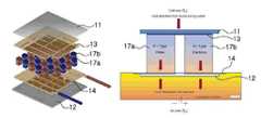
열전소자의 구성은 일반적으로 도 1에 도시된 바와 같이, 제1 기판(11)과 제2 기판(12)이 일정 거리를 두고 서로 이격되게 배치되고, 제1 기판(11)의 내측면과 제2 기판(12)의 내측면에는 각각 전극부재(13,14)가 설치되며, 이 양 전극부재(13,14) 사이에 P형 열전반도체 펠릿(17a)과 N형 열전반도체 펠릿(17b)이 쌍으로 접촉되게 배치되는 구조를 갖는다.1, the
열전소자의 특성상 발열면에서 방열을 효과적으로 해야 흡열면에서 냉각 효율이 좋게 되므로, 열전소자의 성능을 높이기 위해 발열면 기판에 방열핀이 설치된다. 그리고 기판에는 열전도 성능을 높이기 위해 금속 코팅층이 코팅되는데, 금속 코팅층은 전도성능이 좋은 구리(Cu) 재질을 사용하는 것이 보통이다.In order to improve the performance of the thermoelectric device, the heat-radiating fins are provided on the heat-generating surface board because heat radiation from the heat-generating surface is effective for cooling efficiency on the heat-absorbing surface. The substrate is coated with a metal coating layer to improve the thermal conductivity. The metal coating layer is usually made of a copper (Cu) material having good conductivity.
한편 현재 열전소자를 사용한 열교환기의 경우 특별한 방열핀 설치의 위치를 고려하지 않고 방열성능만을 고려하여 방열핀의 형상을 바꾸거나 하는 등의 연구만 진행되었다. 이 때문에 금속 코팅층의 두께를 두껍게 하여 발열면의 온도를 고르게 만들어 특정한 방열핀 설치 위치를 고려하지 않고도 방열을 하는 구조를 사용하고 있다.
On the other hand, in the case of a heat exchanger using a thermoelectric element, only the heat dissipation performance of the heat dissipation fin is changed without taking the position of the heat dissipation fin installation into account. For this reason, the thickness of the metal coating layer is made thick so that the temperature of the heat-generating surface is made uniform, so that the heat dissipation structure is used without considering a specific position of the heat-radiating fin.
본 발명은 상기와 같은 점을 감안하여 안출된 것으로써, 방열핀의 설치 위치를 열전반도체의 배치 구조에 대응되도록 배치하여 방열성능을 더욱 높일 수 있도록 하는 열전모듈 및 이를 구비하는 차량용 시트 냉난방장치를 제공하는데 그 목적이 있다.
SUMMARY OF THE INVENTION The present invention has been made in view of the above circumstances and provides a thermoelectric module and a vehicle seat heating and cooling apparatus having the thermoelectric module to further improve the heat radiation performance by disposing the installation positions of the heat radiation fins so as to correspond to the arrangement structure of the thermoelectric semiconductors It has its purpose.
상기 목적을 달성하기 위한 본 발명에 따른 열전모듈은, 외측면에 금속 코팅층이 각각 형성되며 일정 거리를 두고 서로 이격되게 배치되는 제1 기판 및 제2 기판; 상기 제1 기판과 제2 기판의 마주보는 내측면에 형성된 전극부재를 사이에 두고 접촉되게 배치되는 복수의 열전반도체 펠릿;, 상기 제1 기판 또는 제2 기판 중 적어도 하나의 외측면에 일단이 접촉되게 설치되는 판형(plate type) 방열핀을 포함한다. 여기서 상기 기판과 접촉되는 방열핀의 일단은, 상기 제1 기판 또는 제2 기판 내측에 배치된 상기 열전 반도체 펠릿과 대면하는 위치에 배치된다.According to an aspect of the present invention, there is provided a thermoelectric module including: a first substrate and a second substrate, each having a metal coating layer on an outer surface thereof and spaced apart from each other at a predetermined distance; A plurality of thermoelectric semiconductor pellets disposed in contact with each other with an electrode member formed on an inner surface of the first substrate and the second substrate facing each other; And a plate-type radiating fin to be installed. Wherein one end of the radiating fin in contact with the substrate is disposed at a position facing the thermoelectric semiconductor pellet disposed inside the first substrate or the second substrate.
상기 기판의 금속 코팅층은 알루미늄(Al) 또는 구리(Cu) 재질이 적용될 수 있다.The metal coating layer of the substrate may be made of aluminum (Al) or copper (Cu).
상기 기판의 금속 코팅층은 30~110㎛ 두께로 형성될 수 있다.The metal coating layer of the substrate may be formed to a thickness of 30 to 110 탆.
상기 방열핀은 상기 열전모듈의 길이방향으로 골과 마루가 반복되는 구조를 가지며, 상기 반복되는 골 또는 마루가 상기 기판과 접촉되는 방열핀의 일단일 수 있다.The radiating fins may have a structure in which a valley and a floor are repeated in the longitudinal direction of the thermoelectric module, and the repeated bones or floors may be a single end of the radiating fin contacting the substrate.
상기 방열핀은 핀코루게이트 핀(corrugated fin), 평판 핀(plain fin), 웨이비 핀(wavy fin) 중 어느 하나가 적용될 수 있다.The radiating fin may be a corrugated fin, a plain fin, or a wavy fin.
한편 상기 목적을 달성하기 위한 본 발명에 따른 차량용 시트 냉난방장치는, 차량용 시트로 공기가 이송되는 덕트와 상기 덕트로 공기를 이송시키는 송풍팬을 포함하는 덕트부와, 상기 덕트 내에 배치되어 공기를 냉각 또는 가열시키는 열전모듈을 포함한다. 상기 열전모듈은, 외측면에 금속 코팅층이 각각 형성되며 일정 거리를 두고 서로 이격되게 배치되는 제1 기판 및 제2 기판과, 상기 제1 기판과 제2 기판의 마주보는 내측면에 형성된 전극부재를 사이에 두고 접촉되게 배치되는 복수의 열전반도체 펠릿, 및 상기 제1 기판 및 제2 기판 각각의 외측면에 일단이 접촉되게 설치되는 제1 방열핀 및 제2 방열핀을 포함하며, 상기 덕트부의 덕트는 상기 제1 방열핀을 거쳐 유입된 공기를 상기 차량용 시트로 이송시키는 제1 덕트와, 상기 제2 방열핀을 거쳐 유입된 공기를 배출시키는 제2 덕트로 구분된다. 여기서 상기 기판과 접촉되는 상기 제1 방열핀 및 제2 방열핀 각각의 일단은, 상기 제1 기판 및 제2 기판 내측에 배치된 상기 열전 반도체 펠릿과 대면하는 위치에 배치된다.According to another aspect of the present invention, there is provided a vehicle seat heating and cooling apparatus for a vehicle, comprising: a duct unit including a duct through which air is delivered to a vehicle seat and a blower fan for transferring air to the duct; Or a thermoelectric module for heating. The thermoelectric module includes a first substrate and a second substrate, each having a metal coating layer formed on an outer surface thereof and spaced apart from each other with a predetermined distance therebetween; and an electrode member formed on an inner surface of the first substrate and the second substrate, And a first radiating fin and a second radiating fin which are provided so as to be in contact with an outer surface of each of the first and second substrates, respectively, and the duct of the duct portion is connected to the first radiating fin and the second radiating fin, A first duct for transferring the air introduced through the first radiating fins to the vehicle seat, and a second duct for discharging the air introduced through the second radiating fins. Wherein one end of each of the first radiating fin and the second radiating fin in contact with the substrate is disposed at a position facing the thermoelectric semiconductor pellets disposed inside the first substrate and the second substrate.
상기 기판의 금속 코팅층은 알루미늄 또는 구리 재질일 수 있다.The metal coating layer of the substrate may be made of aluminum or copper.
상기 기판의 금속 코팅층은 30~110㎛ 두께로 형성될 수 있다.The metal coating layer of the substrate may be formed to a thickness of 30 to 110 탆.
상기 방열핀은 상기 열전모듈의 길이방향으로 골과 마루가 반복되는 구조를 가지며, 상기 반복되는 골 또는 마루가 상기 기판과 접촉되는 방열핀의 일단일 수 있다.The radiating fins may have a structure in which a valley and a floor are repeated in the longitudinal direction of the thermoelectric module, and the repeated bones or floors may be a single end of the radiating fin contacting the substrate.
상기 방열핀은 코루게이트 핀(corrugated fin), 평판 핀(plain fin), 웨이비 핀(wavy fin) 중 어느 하나가 적용될 수 있다.
The radiating fin may be a corrugated fin, a plain fin, or a wavy fin.
본 발명에 의하면 방열핀의 설치 위치를 열전반도체의 배치 구조에 대응되도록 설치하여 방열성능을 더욱 높일 수 있는 효과가 있다. 또한 방열성능을 높임으로써 구리 재질의 전극부재의 두께를 줄이도록 하거나 또는 구리 대신 비교적 저렴한 알루미늄 재질의 전극부재를 사용하도록 함으로써 결국 제조비용을 줄일 수 있는 효과가 있다.
According to the present invention, the installation position of the heat dissipation fins is provided so as to correspond to the arrangement structure of the thermoelectric semiconductors, thereby further enhancing the heat radiation performance. Further, by increasing the heat radiation performance, the thickness of the electrode member made of copper can be reduced, or the electrode member made of aluminum can be used in place of copper, thereby reducing the manufacturing cost.
도 1은 일반적인 열전소자의 구조 및 개념을 설명하기 위한 도면,
도 2는 본 발명의 일 실시예에 따른 열전모듈의 정단면도,
도 3은 도 2에서 다른 방열핀이 적용된 상태의 도면,
도 4는 본 발명의 일 실시예에 따른 열전모듈의 열전도도 성능시험을 위한 a)실시예와 b)비교예의 기하학적 구조를 나타낸 도면,
도 5a 내지 도 5c는 도 4의 실시예와 비교예에 따른 기판의 금속 코팅층의 두께별, 재질별 해석 결과를 나타낸 도면,
도 6은 본 발명의 다른 실시예에 따른 열전모듈의 정단면도,
도 7은 도 6의 열전모듈이 적용된 차량용 시트 냉난방장치의 구조도이다.1 is a view for explaining the structure and concept of a general thermoelectric element,
2 is a front sectional view of a thermoelectric module according to an embodiment of the present invention,
FIG. 3 is a view showing a state where another radiating fin is applied in FIG. 2,
FIG. 4 is a diagram illustrating a geometrical structure of an embodiment a) and b) a comparative example for a thermal conductivity test of a thermoelectric module according to an embodiment of the present invention,
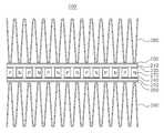
FIGS. 5A to 5C are diagrams showing results of analyzes of thicknesses and materials of the metal coating layer of the substrate according to the embodiment and the comparative example of FIG. 4,
6 is a front sectional view of a thermoelectric module according to another embodiment of the present invention,
7 is a structural view of a vehicle seat heating and cooling apparatus to which the thermoelectric module of Fig. 6 is applied.
본 발명의 상기와 같은 목적, 특징 및 다른 장점들은 첨부도면을 참조하여 본 발명의 실시예를 상세히 설명함으로써 더욱 명백해질 것이다. 이하 첨부된 도면을 참조하여 본 발명의 실시예에 따른 열전모듈 및 이를 구비하는 차량용 시트 냉난방장치에 대해 상세히 설명하기로 한다.These and other objects, features and other advantages of the present invention will become more apparent by describing in detail exemplary embodiments of the present invention with reference to the accompanying drawings. DETAILED DESCRIPTION OF THE PREFERRED EMBODIMENT Hereinafter, a thermoelectric module according to an embodiment of the present invention will be described in detail with reference to the accompanying drawings.
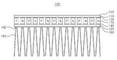
도 2를 참조하면, 본 발명의 일 실시예에 따른 열전모듈(100)은 외측면에 금속 코팅층(150,160)이 각각 형성되며 일정 거리를 두고 서로 이격되게 배치되는 제1 기판(110) 및 제2 기판(120)과, 제1 기판(110)과 제2 기판(120)의 마주보는 내측면에 형성된 전극부재(130,140)를 사이에 두고 접촉되게 배치되는 복수의 열전반도체 펠릿(170)과, 발열면 즉 제2 기판(120)의 외측면에 일단(182)이 접촉되게 설치되는 방열핀(180)을 포함한다.2, a
제1 기판(110)과 제2 기판(120)은 일반적으로 세라믹 재질의 절연 기판이 적용되며, 본 실시예에서는 편의상 상부의 제1 기판(110)을 흡열측 기판으로 하고, 하부의 제2 기판(120)을 발열측 기판으로 하기로 한다.The
양 기판의 외측면에는 열전도도 향상을 위해 금속 코팅층(150,160)이 일정 두께로 형성된다. 상기 금속 코팅층(150,160)은 알루미늄(Al) 또는 구리(Cu) 재질로 적용된다. 또한 상기 금속 코팅층(150,160)은 30~110㎛ 두께로 형성될 수 있다.
양 기판의 내측면에는 각각 전극부재(130,140)가 접합되고, 각 전극부재(130,140)에 P형 및 N형의 열전반도체 펠릿(170)의 상하단이 접하도록 배치된다. 흡열측 전극부재(130) 중, 단부에 위치하는 흡열측 전극부재는 P형 열전반도체 펠릿 또는 N형 열전반도체 펠릿 1개만 접하게 된다. 그리고 그 이외에 흡열측 전극부재(130) 및 방열측 전극부재(140)에는 P형 및 N형 열전반도체 펠릿(170)이 각각 1개씩 즉, 한 쌍으로 접하도록 배치된다. 한편 1개의 방열측 전극부재(140)에 접하고 있는 P형 열전반도체 펠릿 또는 N형 열전반도체 펠릿(170)은 각각 다른 흡열측 전극부재(130)에 접하게 되고, 마찬가지로 1개의 흡열측 전극부재(130)에 접하고 있는 P형 열전반도체 펠릿 또는 N형 열전반도체 펠릿은 각각 다른 방열측 전극부재(140)에 접하게 된다.The
이와 같은 배치에 의해 흡열측 전극부재(130), P형 열전반도체 펠릿(170), 방열측 전극부재(140), N형 열전반도체 펠릿(170) 순서로 반복해서 전기적으로 직렬 접속된다. 따라서 미도시된 리드선에 진류 전압을 인가하면, 전류는 흡열측 전극부재(130), P형 열전반도체 펠릿(170), 방열측 전극부재(140), N형 열전반도체 펠릿(170) 순으로 흐르고, 이 때 펠티에 효과에 의해 상부의 제1 기판(110)은 흡열면이 되고 하부의 제2 기판(120)은 발열면이 된다.With this arrangement, the heat absorbing
한편 방열핀(180)의 일단(182)은 상기 제2 기판(120)의 외측면에 접하도록 설치되는데, 이 때 방열핀(180)의 일단(182)은 제2 기판(120) 내측에 배치된 상기 열전반도체 펠릿(170)과 대면하는 위치에 접촉된다. 여기서 열전반도체 펠릿(170)과 대면하는 위치라 함은, 도시된 바와 같이 제2 기판(120)과 접하는 방열핀(180)의 일단(182) 즉, 접점면이 열전반도체 펠릿(170)의 가로 폭 내에 위치하는 것을 의미한다.One
방열핀(180)은 판형(plate type) 핀으로써 본 발명의 실시예에 의하면 방열핀(180)은 열전모듈(100)의 가로 방향(도면상의 제2 기판(또는 제1 기판)의 좌우 방향)으로 골과 마루가 주기적으로 반복되는 구조가 적용된다. 여기서 도시된 바와 같이 방열핀(180)의 마루가 제2 기판(120)과의 접점면이 되고, 따라서 이 복수의 접점면이 모두 각각의 열전반도체 펠릿(170)의 가로 폭 내에 위치하게 된다. 방열핀(180)의 접점면이 열전반도체 가로 폭 내부에 위치하기만 하면 본 발명의 범위에 속하는데, 가능한 방열핀(180)의 접점면은 열전반도체의 중앙부에 위치하는 것이 가장 바람직하다.According to the embodiment of the present invention, the
골과 마루가 주기적으로 반복되는 구조의 판형 핀이면 방열핀에 제한없이 적용되는데, 본 발명의 실시예에 의하면 도 2와 같이 주름진 구조의 코루게이트 핀(corrugated fin, 180)이 적용되거나, 또는 도 3과 같이 평판 핀(plain fin, 190)이 적용될 수도 있다. 또한 방열핀은 핀 벽(wall)이 웨이브진 형상의 웨이비 핀(wavy fin)이 적용될 수 있다. 코루게이트 핀은 주름진 구조의 핀을 의미하는 것으로 루버 핀(louver fin)을 포함하는 개념으로 해석될 수 있다. 그리고 평판 핀은 핀 벽이 평면 구조이나, 웨이비 핀은 핀 벽이 유체의 흐름 방향 즉, 열전모듈의 세로 방향으로 웨이브(wave) 구조를 갖게 된다.The
한편 도시하지 않았으나 본 발명에 따른 열전모듈은 상기 방열핀(180)의 외곽을 둘러싸는 케이스가 별도로 설치될 수 있어 히트싱크(heat sink)의 역할을 할 수 있다.Although not shown, the thermoelectric module according to the present invention may have a case surrounding the outer periphery of the
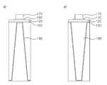
도 4는 본 발명의 일 실시예에 따른 열전모듈(100)의 열전도도 성능시험을 위한 기하학적 구조를 나타낸 것으로써, 좌측 a) 도면은 본 발명의 일 실시예에 따른 열전모듈(100)에서 방열핀(180)의 접합면(182)이 열전반도체 펠릿(170)의 중앙부에 위치한 것을, 우측 b) 도면은 비교예를 나타낸 것이다. 비교예에 따른 열전모듈은 기판(120)에 접하는 방열핀(180')의 일단(접합면)이 열전반도체 펠릿(170)과 대면하지 않는 위치, 즉 열전반도체 펠릿(170)의 가로 폭 내에 위치하지 않게 된다.4 shows a geometrical structure for testing the thermal conductivity of the
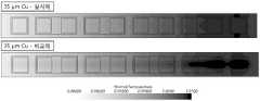
도 5a 내지 도 5c는 도 4의 실시예와 비교예에 따른 금속 코팅층의 두께별(35㎛, 105㎛), 재질별(Cu, Al) 온도분포 해석 결과를 나타낸 것이다.Figs. 5A to 5C show the results of temperature distribution analysis (Cu, Al) of the metal coating layer (35 mu m, 105 mu m) and the material (Cu, Al) according to the embodiment and the comparative example of Fig.
도시된 바와 같이 비교예의 경우 우측으로 갈수록 핫스팟(hot spot, 진한 검은색 부분)이 선명하게 나타나나, 실시예의 경우 핫스팟(hot spot)이 발생되지 않거나 또는 거의 발생되지 않음을 알 수 있다. 특히 금속 코팅층이 35㎛ 일 때, 방열핀이 어디 붙어있느냐에 따라 실제 단일 열전반도체 위(정사각형 모양 부분)의 온도분포가 달라짐을 확인하실 수 있다.As shown in the figure, in the comparative example, hot spots (dark black portions) appear clearly toward the right side, but hot spots do not occur or hardly occur in the embodiment. In particular, when the metal coating layer is 35 μm, it can be seen that the temperature distribution on the actual single thermoelectric semiconductor (square shape portion) varies depending on where the radiating fin is attached.
이와 같이 열전모듈의 흡열면에서의 냉각 열량은 발열면에서의 온도에 영향을 받기 때문에, 열전모듈의 냉각 성능을 높이기 위해서는 열전반도체 자체에 핫스팟이 발생하지 않아야 한다. 핫스팟이 발생하게 되면 열전반도체가 금속이기 때문에 금속내부를 통한 전도로 인해 열이 고온부에서 저온부로 즉, 발열면에서 흡열면으로 흐르게 되는데, 일반적으로 열전소자의 열전도도는 금속 중 매우 낮은 편이지만, 전도를 통한 열손실이 발생하기 때문에 냉각성능에 저해하는 역할을 하게 된다.Since the amount of cooling heat on the heat absorption surface of the thermoelectric module is influenced by the temperature on the heat generation surface, hot spots must not occur in the thermoelectric semiconductor itself in order to improve the cooling performance of the thermoelectric module. When a hot spot is generated, the thermoelectric semiconductor is a metal. Therefore, heat is conducted from the high temperature portion to the low temperature portion, that is, from the heat generating surface to the heat absorbing surface due to conduction through the metal. Generally, the thermal conductivity of the thermoelectric element is very low, The heat loss due to conduction is generated, thereby acting as a hindrance to the cooling performance.
본 발명의 실시예에 의하면 방열핀을 열전소자의 바로 위에 설치함으로써 핫스팟이 발생되지 않게 되는 이점이 있다.According to the embodiment of the present invention, there is an advantage that hot spots are not generated by providing the heat radiating fins directly above the thermoelectric elements.
한편 금속 코팅층이 105㎛ 일 경우 실시예와 비교예의 경우 차이가 별로 없음을 알 수 있다. 일반적으로 금속 코팅층은 35㎛ 단위로 가능한데 현재 열전모듈의 기판에는 전도성능이 좋은 구리(Cu) 재질로 105㎛ 코팅되어 제작되는 것이 일반적이다. 그 이유는 전술한 바와 같이 현재 열전반도체의 방열핀 설치 위치를 고려하지 않기 때문에 금속 코팅층의 두께를 두껍게 하여 발열면의 온도를 고르게 하여 특정한 방열핀 설치 위치를 고려하지 않고도 방열을 하는 구조이기 때문이다. 따라서 방열핀이 열전소자의 위치와는 상관없이 배치될 경우 비교예와 같이 가장 안 좋은 케이스의 경우에도 핫스팟이 덜 생기도록 하기 위함이다.On the other hand, in the case of the metal coating layer having a thickness of 105 mu m, it can be seen that there is not much difference between the embodiment and the comparative example. Generally, the metal coating layer can be formed in a unit of 35 μm, and the substrate of the thermoelectric module is generally coated with a copper (Cu) material having a good conduction performance. This is because, as described above, since the installation position of the heat-radiating fin of the current thermoelectric semiconductor is not considered, the thickness of the metal coating layer is increased to uniform the temperature of the heat-generating surface to dissipate heat without considering a specific installation position of the heat- Therefore, when the heat radiating fins are disposed irrespective of the positions of the thermoelectric elements, the hot spots are less likely to occur even in the case of the worst case as in the comparative example.
따라서 본 발명에 의하면 금속 코팅층을 얇게(35㎛) 할 수 있기 때문에 비용 역시 절감할 수 있으며, 알루미늄(Al)이 구리(Cu)보다 싸기 때문에 구리가 아닌 알루미늄으로 기판에 금속 코팅할 때에도 성능적으로 문제가 되지 않기 때문에 비용절감이 가능해지는 이점이 있다. Therefore, according to the present invention, since the metal coating layer can be made thin (35 탆), the cost can be reduced. Also, since aluminum (Al) is cheaper than copper (Cu) There is an advantage that the cost can be saved because it is not a problem.
도 6을 참조하면, 본 발명의 다른 실시예에 따른 열전모듈(200)은 양 기판 즉, 제1 기판(210) 및 제2 기판(220)의 외측면 각각에 제1 방열핀(280) 및 제2 방열핀(290)이 설치된 구조를 갖는다. 여기서 제2 방열핀(290)의 마루가 제2 기판(220)과의 접점면이 되고, 제1 방열핀(280)의 골이 제1 기판(210)이 제1 기판(210)과의 접점면이 되며, 따라서 이 복수의 접점면이 모두 각각의 열전반도체 펠릿(170)과 대면하는 위치 즉 열전반도체의 가로 폭 내에 위치하게 된다.6, the
본 발명의 다른 실시예에 따른 열전모듈(200)은 방열핀(280,290)이 양 기판에 각각 설치된 것을 제외하고는 앞선 도 2의 본 발명의 일 실시예에 따른 열전모듈(100)과 동일한 구성을 가지므로 상세한 설명은 생략하기로 한다.The
본 발명의 일 실시예에 따른 열전모듈(100)은 주로 냉각기로 사용되고, 본 발명의 다른 실시예에 따른 열전모듈(200)은 냉각 및 난방 장치로 사용하게 되는데 이는 전원 극성을 반대로 해주는 경우 흡열면과 방열면이 반대로 되는 열전소자의 특성을 이용한 것이다.The
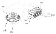
도 7은 본 발명의 다른 실시예에 따른 열전모듈(200)이 적용된 차량용 시트 냉난방장치(300)를 나타낸 것이다.FIG. 7 shows a vehicle seat cooling / heating apparatus 300 to which a
차량용 시트 냉난방장치(300)는 덕트부(305)와 열전모듈(200)를 포함한다. 덕트부(305)는 송풍팬(320)이 구비되는 송풍팬 하우징(330)과, 송풍팬(320)에 의해 이송되는 공기를 차량용 시트(미도시)로 안내하는 덕트(310)로 구성된다. 열전모듈(200)은 상기 덕트(310) 내에 배치되어 공기를 냉각 또는 가열시키게 된다.The vehicle seat heating and cooling apparatus 300 includes a
상기 열전모듈(200)은 전술한 바와 같이, 외측면에 금속 코팅층(250,260)이 각각 형성되며 일정 거리를 두고 서로 이격되게 배치되는 제1 기판(210) 및 제2 기판(220)과, 상기 제1 기판(210)과 제2 기판(220)의 마주보는 내측면에 전극부재(230,240)를 사이에 두고 접촉되게 배치되는 복수의 열전반도체 펠릿(270), 및 상기 제1 기판(210) 및 제2 기판(220) 각각의 외측면에 일단이 접촉되게 설치되는 제1 방열핀(280) 및 제2 방열핀(290)을 포함한다. 그리고 상기 제1 방열핀(280) 및 제2 방열핀(290) 각각의 일단은 상기 제1 기판(210) 및 제2 기판(220) 내측에 배치된 상기 열전반도체 펠릿(270)과 대면하는 위치에 접촉되는 것 역시 앞서 설명한 바와 같다.As described above, the
상기 덕트부(305)의 덕트(310)는 상기 제1 방열핀(280)을 거쳐 유입된 공기를 차량용 시트로 이송시키는 제1 덕트(312)와, 상기 제2 방열핀(290)을 거쳐 유입된 공기를 배출시키는 제2 덕트(314)로 구분된다.The
따라서 예를 들어 열전모듈(100)로 순방향의 전류가 인가되어 열전모듈(200)의 상부면(제1 기판)이 발열되는 경우, 열전모듈(200)의 상부면에 접촉된 제1 방열핀(280)의 온도는 상승하게 되는데, 이 때 송풍팬(320)에 의해 이송된 공기는 제1 방열핀(280)과 열교환되어 온도가 상승하게 된다. 가열된 공기는 제1 덕트(312)를 따라 차량용 시트로 이송되어 차량용 시트를 가열하게 된다. 한편 열전모듈(200)의 상부면이 발열되는 경우 열전모듈의 하부면(제2 기판)은 흡열되므로 이에 접촉된 제2 방열핀(290)의 온도는 하강하게 된다. 따라서 송풍팬에 의해 이송된 공기는 제2 방열핀(290)과 열교환되어 온도가 하강하게 되고 제2 덕트(314)를 통해 배출된다.Therefore, when a forward current is applied to the
반대로 열전모듈(200)로 역방향의 전류가 인가되어 열전모듈(200)의 상부면이 흡열되는 경우, 열전모듈(200)의 상부면(제1 기판)에 접촉된 제1 방열핀(280)의 온도는 하강하게 되는데, 이 때 송풍팬(320)에 의해 이송된 공기는 제1 방열핀(280)과 열교환되어 온도가 하강하게 된다. 냉각된 공기는 제1 덕트(312)를 따라 차량용 시트로 이송되어 차량용 시트를 냉각시키게 된다. 한편 열전모듈(200)의 상부면이 흡열되는 경우 열전모듈의 하부면(제2 기판)은 발열되므로 이에 접촉된 제2 방열핀(290)의 온도는 상승하게 된다. 따라서 송풍팬에 의해 이송된 공기는 제2 방열핀(290)과 열교환되어 온도가 상승하게 되고 제2 덕트(314)를 통해 배출된다.The temperature of the
이상에서 본 발명의 바람직한 실시예에 대하여 설명하였으나 본 발명은 상술한 특정의 실시예에 한정되지 아니한다. 즉, 본 발명이 속하는 기술분야에서 통상의 지식을 가지는 자라면 첨부된 특허청구범위의 사상 및 범주를 일탈함이 없이 본 발명에 대한 다수의 변경 및 수정이 가능하며, 그러한 모든 적절한 변경 및 수정의 균등물들도 본 발명의 범위에 속하는 것으로 간주되어야 할 것이다.
Although the preferred embodiments of the present invention have been described, the present invention is not limited to the specific embodiments described above. It will be apparent to those skilled in the art that numerous modifications and variations can be made in the present invention without departing from the spirit or scope of the appended claims. And equivalents should also be considered to be within the scope of the present invention.
100,200. 열전모듈110,210. 제1 기판
120,220. 제2 기판130,140,230,240. 전극부재
150,160,250,260. 금속 코팅층170,270. 열전반도체 펠릿
180,280,290. 방열핀300. 차량용 시트 냉난방장치
305. 덕트부310. 덕트
320. 송풍팬330. 송풍팬 하우징100, 200.
120, 220. The
150, 160, 250, 260.
180,280,290. Radiating Pin 300. Car Seat Heating /
305.
320.
Claims (10)
Translated fromKorean상기 제1 기판의 상기 제2 기판과 대면하는 내측면에 접합되는 전극부재와 상기 제2 기판의 상기 제1 기판과 대면하는 내측면에 접합되는 전극부재의 사이에 배치되는 복수의 열전반도체 펠릿;
골과 마루가 주기적으로 반복되는 구조를 가지며, 상기 제1 기판 또는 제2 기판 중 적어도 하나의 외측면에 상기 골 또는 상기 마루가 접촉되게 설치되는 판형(plate type) 방열핀을 포함하며,
상기 기판과 접촉되는 상기 골 또는 마루는 상기 제1 기판 또는 상기 제2 기판을 사이에 두고 상기 열전 반도체 펠릿과 대면하게 배치되고,
상기 골 또는 마루는 상기 열전 반도체 펠릿의 가로 폭 내에 배치되는 것을 특징으로 하는 열전모듈.
A first substrate and a second substrate having metal coating layers formed on outer surfaces thereof and spaced apart from each other with a predetermined distance therebetween;
A plurality of thermoelectric semiconductor pellets disposed between an electrode member joined to an inner surface of the first substrate facing the second substrate and an electrode member bonded to an inner surface of the second substrate facing the first substrate;
And a plate type radiating fin having a structure in which the valley and the floor are periodically repeated, and a plate or radiating fin provided on the outer side of at least one of the first and second substrates so as to be in contact with the valley or the floor,
Wherein the trough or floor contacting with the substrate is arranged to face the thermoelectric semiconductor pellet with the first substrate or the second substrate interposed therebetween,
Wherein said bones or floors are disposed within a width of the thermoelectric semiconductor pellet.
상기 기판의 금속 코팅층은 알루미늄(Al) 또는 구리(Cu) 재질인 것을 특징으로 하는 열전모듈.
The method according to claim 1,
Wherein the metal coating layer of the substrate is made of aluminum (Al) or copper (Cu).
상기 기판의 금속 코팅층은 30~110㎛ 두께로 형성되는 것을 특징으로 하는 열전모듈.
3. The method of claim 2,
Wherein the metal coating layer of the substrate is formed to a thickness of 30 to 110 占 퐉.
상기 방열핀은 코루게이트 핀(corrugated fin), 평판 핀(plain fin), 웨이비 핀(wavy fin) 중 어느 하나가 적용되는 것을 특징으로 하는 열전모듈.
The method according to claim 1,
Wherein the heat dissipation fin is one of a corrugated fin, a plain fin, and a wavy fin.
상기 열전모듈은,
외측면에 금속 코팅층이 각각 형성되며 일정 거리를 두고 서로 이격되게 배치되는 제1 기판 및 제2 기판;
상기 제1 기판의 상기 제2 기판과 대면하는 내측면에 접합되는 전극부재와 상기 제2 기판의 상기 제1 기판과 대면하는 내측면에 접합되는 전극부재의 사이에 배치되는 복수의 열전반도체 펠릿;
골과 마루가 주기적으로 반복되는 구조를 가지며, 상기 제1 기판의 외측면에 상기 골이 접촉되게 설치되는 제1 방열핀; 및
골과 마루가 주기적으로 반복되는 구조를 가지며, 상기 제2 기판의 외측면에 상기 마루가 접촉되게 설치되는 제2 방열핀을 포함하며,
상기 덕트부의 덕트는 상기 제1 방열핀을 거쳐 유입된 공기를 상기 차량용 시트로 이송시키는 제1 덕트와 상기 제2 방열핀을 거쳐 유입된 공기를 배출시키는 제2 덕트로 구분되며,
상기 제1 기판과 접촉되는 상기 제1 방열핀의 상기 골은 상기 제1 기판을 사이에 두고 상기 열전 반도체 펠릿과 대면하게 배치되고,
상기 제2 기판과 접촉되는 상기 제2 방열핀의 상기 마루는 상기 제2 기판을 사이에 두고 상기 열전 반도체 펠릿과 대면하게 배치되고,
상기 제1 방열핀의 상기 골과 상기 제2 방열핀의 상기 마루는 상기 열전 반도체 펠릿의 가로 폭 내에 배치되는 것을 특징으로 하는 차량용 시트 냉난방 장치.
1. A vehicular seat air conditioning apparatus comprising a duct section including a duct through which air is delivered to a vehicle seat and an air blowing fan for transferring air to the duct, and a thermoelectric module disposed in the duct to cool or heat the air,
The thermoelectric module includes:
A first substrate and a second substrate having metal coating layers formed on outer surfaces thereof and spaced apart from each other with a predetermined distance therebetween;
A plurality of thermoelectric semiconductor pellets disposed between an electrode member joined to an inner surface of the first substrate facing the second substrate and an electrode member bonded to an inner surface of the second substrate facing the first substrate;
A first radiating fin having a structure in which valleys and a floor are periodically repeated, the first radiating fins being provided on an outer side of the first substrate so as to be in contact with the valleys; And
And a second radiating fin having a structure in which the valley and the floor are periodically repeated, and the floor is placed in contact with the outer surface of the second substrate,
The duct of the duct portion is divided into a first duct for transferring the air introduced through the first radiating fin to the vehicle seat and a second duct for discharging the air introduced through the second radiating fin,
The troughs of the first radiating fins being in contact with the first substrate are arranged to face the thermoelectric semiconductor pellets with the first substrate interposed therebetween,
The floor of the second radiating fin contacting with the second substrate faces the thermoelectric semiconductor pellet with the second substrate interposed therebetween,
Wherein the valley of the first radiating fin and the floor of the second radiating fin are disposed within a width of the thermoelectric semiconductor pellet.
상기 기판의 금속 코팅층은 알루미늄 또는 구리 재질인 것을 특징으로 하는 차량용 시트 냉난방 장치.
The method according to claim 6,
Wherein the metal coating layer of the substrate is made of aluminum or copper.
상기 기판의 금속 코팅층은 30~110㎛ 두께로 형성되는 것을 특징으로 하는 차량용 시트 냉난방 장치.
8. The method of claim 7,
Wherein the metal coating layer of the substrate is formed to a thickness of 30 to 110 占 퐉.
상기 방열핀은 코루게이트 핀(corrugated fin), 평판 핀(plain fin), 웨이비 핀(wavy fin) 중 어느 하나가 적용되는 것을 특징으로 하는 차량용 시트 냉난방 장치.
The method according to claim 6,
Wherein the radiating fin is one of a corrugated fin, a plain fin, and a wavy fin.
Priority Applications (1)
| Application Number | Priority Date | Filing Date | Title |
|---|---|---|---|
| KR1020140195265AKR101753322B1 (en) | 2014-12-31 | 2014-12-31 | Thermoelectic moudule and Apparatus for cooling and heating a vehicle seat having the same |
Applications Claiming Priority (1)
| Application Number | Priority Date | Filing Date | Title |
|---|---|---|---|
| KR1020140195265AKR101753322B1 (en) | 2014-12-31 | 2014-12-31 | Thermoelectic moudule and Apparatus for cooling and heating a vehicle seat having the same |
Publications (2)
| Publication Number | Publication Date |
|---|---|
| KR20160081434A KR20160081434A (en) | 2016-07-08 |
| KR101753322B1true KR101753322B1 (en) | 2017-07-11 |
Family
ID=56503676
Family Applications (1)
| Application Number | Title | Priority Date | Filing Date |
|---|---|---|---|
| KR1020140195265AActiveKR101753322B1 (en) | 2014-12-31 | 2014-12-31 | Thermoelectic moudule and Apparatus for cooling and heating a vehicle seat having the same |
Country Status (1)
| Country | Link |
|---|---|
| KR (1) | KR101753322B1 (en) |
Families Citing this family (5)
| Publication number | Priority date | Publication date | Assignee | Title |
|---|---|---|---|---|
| WO2018084547A1 (en)* | 2016-11-04 | 2018-05-11 | 엘지이노텍 주식회사 | Cooling and heating device |
| KR102405457B1 (en)* | 2018-01-23 | 2022-06-07 | 엘지이노텍 주식회사 | Thermoelectric device module |
| CN112802954A (en)* | 2019-11-13 | 2021-05-14 | 银河制版印刷有限公司 | Thermoelectric power generation device and manufacturing method thereof |
| CN114650711A (en)* | 2022-03-28 | 2022-06-21 | 南昌黑鲨科技有限公司 | An integrated heat dissipation component and radiator |
| CN114793764A (en)* | 2022-04-25 | 2022-07-29 | 武汉理工大学 | Fungus mushroom case with even air current shape function |
Citations (2)
| Publication number | Priority date | Publication date | Assignee | Title |
|---|---|---|---|---|
| KR101435669B1 (en) | 2011-12-23 | 2014-09-23 | 한라비스테온공조 주식회사 | A Thermo-Electric Power Generating Heat Exchanger and Module |
| JP5609967B2 (en)* | 2010-02-26 | 2014-10-22 | 富士通株式会社 | Power generation device, power generation method, and method of manufacturing power generation device |
- 2014
- 2014-12-31KRKR1020140195265Apatent/KR101753322B1/enactiveActive
Patent Citations (2)
| Publication number | Priority date | Publication date | Assignee | Title |
|---|---|---|---|---|
| JP5609967B2 (en)* | 2010-02-26 | 2014-10-22 | 富士通株式会社 | Power generation device, power generation method, and method of manufacturing power generation device |
| KR101435669B1 (en) | 2011-12-23 | 2014-09-23 | 한라비스테온공조 주식회사 | A Thermo-Electric Power Generating Heat Exchanger and Module |
Also Published As
| Publication number | Publication date |
|---|---|
| KR20160081434A (en) | 2016-07-08 |
Similar Documents
| Publication | Publication Date | Title |
|---|---|---|
| KR101753322B1 (en) | Thermoelectic moudule and Apparatus for cooling and heating a vehicle seat having the same | |
| CN108987359B (en) | Radiators and Radiator Components | |
| TWI619430B (en) | Heat sink | |
| KR20150130168A (en) | Device using thermoelectric moudule | |
| US20120217630A1 (en) | Heatsink, heatsink assembly, semiconductor module, and semiconductor device with cooling device | |
| CN102446878A (en) | Semiconductor refrigerating device | |
| JPH06151979A (en) | Thermoelectric device | |
| JP2008078587A (en) | Heat exchange fins | |
| JPH07106640A (en) | Thermoelectric cooling unit | |
| US20100218512A1 (en) | Heat exchanger for thermoelectric applications | |
| KR20160023517A (en) | Heat sink having thermoconductive core and light source apparatus comprising the same | |
| KR20160044279A (en) | Device using thermoelectric moudule | |
| JP2011082272A (en) | Thermoelectric cooling device | |
| KR101451160B1 (en) | Water cooling type and air cooling type thermoelement system | |
| CN114423245A (en) | Semiconductor cooling assembly and radiator | |
| JP2008108781A (en) | Cooling system | |
| CN222703617U (en) | Radiator, refrigerating device and electrical equipment | |
| JP2007043075A (en) | Thermoelectric converter | |
| CN218851204U (en) | Heat dissipation module and refrigerating device | |
| KR101306862B1 (en) | Thermoelectric power generation system for car | |
| TW201414980A (en) | Heat sink | |
| KR100414379B1 (en) | Cooling element | |
| KR20150080255A (en) | Thermoelectric element cooling and heating apparatus | |
| US20080271462A1 (en) | Thermal electric hvac module | |
| JP5181879B2 (en) | Heat sink and heat dissipation system |
Legal Events
| Date | Code | Title | Description |
|---|---|---|---|
| A201 | Request for examination | ||
| PA0109 | Patent application | Patent event code:PA01091R01D Comment text:Patent Application Patent event date:20141231 | |
| PA0201 | Request for examination | ||
| E902 | Notification of reason for refusal | ||
| PE0902 | Notice of grounds for rejection | Comment text:Notification of reason for refusal Patent event date:20160418 Patent event code:PE09021S01D | |
| PG1501 | Laying open of application | ||
| E902 | Notification of reason for refusal | ||
| PE0902 | Notice of grounds for rejection | Comment text:Notification of reason for refusal Patent event date:20161128 Patent event code:PE09021S01D | |
| E701 | Decision to grant or registration of patent right | ||
| PE0701 | Decision of registration | Patent event code:PE07011S01D Comment text:Decision to Grant Registration Patent event date:20170621 | |
| PR0701 | Registration of establishment | Comment text:Registration of Establishment Patent event date:20170627 Patent event code:PR07011E01D | |
| PR1002 | Payment of registration fee | Payment date:20170628 End annual number:3 Start annual number:1 | |
| PG1601 | Publication of registration | ||
| PR1001 | Payment of annual fee | Payment date:20200626 Start annual number:4 End annual number:4 | |
| PR1001 | Payment of annual fee | Payment date:20210628 Start annual number:5 End annual number:5 | |
| PR1001 | Payment of annual fee | Payment date:20220609 Start annual number:6 End annual number:6 | |
| PR1001 | Payment of annual fee | Payment date:20230628 Start annual number:7 End annual number:7 |