KR101752971B1 - Lead moulding device for makeup utensils - Google Patents
Lead moulding device for makeup utensilsDownload PDFInfo
- Publication number
- KR101752971B1 KR101752971B1KR1020150134418AKR20150134418AKR101752971B1KR 101752971 B1KR101752971 B1KR 101752971B1KR 1020150134418 AKR1020150134418 AKR 1020150134418AKR 20150134418 AKR20150134418 AKR 20150134418AKR 101752971 B1KR101752971 B1KR 101752971B1
- Authority
- KR
- South Korea
- Prior art keywords
- core
- pencil
- raw material
- molding die
- shim
- Prior art date
- Legal status (The legal status is an assumption and is not a legal conclusion. Google has not performed a legal analysis and makes no representation as to the accuracy of the status listed.)
- Active
Links
- 238000000465mouldingMethods0.000titleclaimsabstractdescription42
- 239000002994raw materialSubstances0.000claimsabstractdescription34
- 230000008878couplingEffects0.000claimsabstractdescription8
- 238000010168coupling processMethods0.000claimsabstractdescription8
- 238000005859coupling reactionMethods0.000claimsabstractdescription8
- 238000002347injectionMethods0.000claimsabstractdescription7
- 239000007924injectionSubstances0.000claimsabstractdescription7
- 238000003780insertionMethods0.000claimsdescription3
- 230000037431insertionEffects0.000claimsdescription3
- 239000002537cosmeticSubstances0.000abstractdescription15
- 239000000463materialSubstances0.000abstractdescription7
- 210000004709eyebrowAnatomy0.000abstractdescription2
- 238000004519manufacturing processMethods0.000abstractdescription2
- 238000007599dischargingMethods0.000abstract1
- 239000011162core materialSubstances0.000description19
- 239000002184metalSubstances0.000description4
- 238000000034methodMethods0.000description2
- 230000004048modificationEffects0.000description1
- 238000012986modificationMethods0.000description1
- 238000003825pressingMethods0.000description1
- 229920003002synthetic resinPolymers0.000description1
- 239000000057synthetic resinSubstances0.000description1
- 239000002023woodSubstances0.000description1
Images


Classifications
- A—HUMAN NECESSITIES
- A45—HAND OR TRAVELLING ARTICLES
- A45D—HAIRDRESSING OR SHAVING EQUIPMENT; EQUIPMENT FOR COSMETICS OR COSMETIC TREATMENTS, e.g. FOR MANICURING OR PEDICURING
- A45D40/00—Casings or accessories specially adapted for storing or handling solid or pasty toiletry or cosmetic substances, e.g. shaving soaps or lipsticks
- A45D40/20—Pencil-like cosmetics; Simple holders for handling stick-shaped cosmetics or shaving soap while in use
- A—HUMAN NECESSITIES
- A45—HAND OR TRAVELLING ARTICLES
- A45D—HAIRDRESSING OR SHAVING EQUIPMENT; EQUIPMENT FOR COSMETICS OR COSMETIC TREATMENTS, e.g. FOR MANICURING OR PEDICURING
- A45D40/00—Casings or accessories specially adapted for storing or handling solid or pasty toiletry or cosmetic substances, e.g. shaving soaps or lipsticks
- A45D40/30—Masks for marking lips or eyelashes
- B—PERFORMING OPERATIONS; TRANSPORTING
- B43—WRITING OR DRAWING IMPLEMENTS; BUREAU ACCESSORIES
- B43K—IMPLEMENTS FOR WRITING OR DRAWING
- B43K19/00—Non-propelling pencils; Styles; Crayons; Chalks
- B43K19/16—Making non-propelling pencils
- B43K19/18—Making pencil writing-cores
Landscapes
- Moulds For Moulding Plastics Or The Like (AREA)
Abstract
Translated fromKoreanDescription
Translated fromKorean본 발명은 화장용구용 심 성형장치에 관한 것으로서, 더욱 상세하게는 금형에서 일정 직경과 길이를 가지는 심을 성형하여 화장용 연필 등의 화장용구에 결합하여 사용할 수 있도록 된 화장용구용 심 성형장치에 관한 것이다.BACKGROUND OF THE INVENTION 1. Field of the Invention [0001] The present invention relates to a shoemaker for a cosmetic shoe, and more particularly, to a shoemaker for a cosmetic shoe that is formed by molding a shoe having a predetermined diameter and a length in a metal mold, will be.
일반적으로 눈썹, 아이라인 또는 입술라인 등에 화장을 할 때에는 화장용 연필을 사용하게 되는데 이와 같은 화장용 연필은 목재 또는 합성수지재로 이루어지는 연필 몸체의 내부에 소정의 색상을 가지고 일정 직경 및 일정 길이를 가지는 심을 성형한 후 결합 또는 일체로 성형하여 사용하게 된다.In general, a cosmetic pencil is used for making eyebrows, an eye line, a lip line, and the like. Such a pencil for cosmetic is a pencil having a predetermined color and a predetermined diameter and a predetermined length inside a pencil body made of wood or synthetic resin The shim is molded and then joined or integrally molded.
종래에 이와 같은 화장용구용 심을 성형하고 이를 조립하는 장치는 등록 실용신안 제20-0161805호에 개시한 바와 같이 기대의 상측에 복수 개의 배출핀을 가지는 습동체가 결합되고, 상기 습동체의 상측에는 상기 배출핀으로 원료를 주입할 수 있는 주입구를 형성한 성형 금형이 스프링에 의해 탄성적으로 결합된 구성으로 이루어지며, 상기 성형 금형의 주입구에 심 원료를 주입하고 응고 시킨 후 주입구의 상측에 연필이나 립스틱 등의 판체를 위치시키고 상기 습동체를 상승시키면 배출핀 내의 심이 판체 내에 형성된 수용공으로 삽입됨으로써 결합이 이루어지게 된다.Conventionally, an apparatus for molding and assembling such a shoe for shoe sole is disclosed in Japanese Utility Model Registration No. 20-0161805, in which a humidifying member having a plurality of exhaust fins is coupled to an upper side of a base, And a molding die having an injection port capable of injecting a raw material into the discharge pin is elastically coupled by a spring. The core material is injected into the injection port of the molding die and solidified. Then, a pencil When the plate body such as a lipstick is positioned and the humidifying body is raised, the shim in the discharge fin is inserted into the receiving hole formed in the plate body, thereby making the coupling.
그러나 이와 같은 종래의 장치는 하부가 폐쇄된 배출핀 내로 원료를 투입함으로써 원료와 함께 유입되는 공기에 의해 성형된 심에 기포가 발생되는 등 심의 품질이 저하될 뿐만 아니라 원료의 투입 시간이 많이 소요되어 작업 생산성이 저하되는 문제점들이 내재되어 있었다.However, in such a conventional apparatus, bubbles are generated in the core formed by the air introduced together with the raw material by injecting the raw material into the discharge pin which is closed at the bottom, and the quality of the core is deteriorated, And problems in which work productivity is deteriorated are inherent.
이런 문제점들을 해결하기 위하여 종래에도 본 출원인에 의해 개시된 특허 제10-1548887호가 제안되어 있으며, 이는 도 1에 도시한 바와 같이 성형 금형(10)의 내부에 수직 방향으로 복수 개의 심성형부(11)를 형성하고, 상부에는 원료를 상기 심성형부(11)로 유도하는 원료 유도부(12)가 형성되어 있으며, 상기 성형 금형(10)의 상측에는 원료를 주입하기 위한 원료 주입구(13a)를 가지는 커버판(13)이 결합되고, 하부에는 배출구(14a)를 형성한 하부판(14)이 결합되는 화장용구용 심 성형장치이다.In order to solve these problems, Japanese Unexamined Patent Publication No. 10-1548887, which was proposed by the applicant of the present invention, proposes a method of forming a plurality of imaginary-
그러나 이와 같은 장치는 하부판(14)에 형성된 배출구(14a) 상측에 뾰족하게 형성된 뾰족부(14b)로 인하여 심의 선단이 뾰족하게 되는 심을 성형하는 데에는 어느 정도 이점이 있으나, 일반적으로 사용하는 상단 및 하단이 평탄한 심의 경우에는 적용하기 어렵고, 평탄한 심을 성형할 경우에는 금형의 구조를 변경해야 함으로써 비용이 발생되는 등의 문제점이 있었다.However, such a device has some advantages in forming a core having a pointed tip of the core due to the
본 발명은 상술한 종래 기술의 문제점들을 해결하기 위하여 발명된 것으로서, 본 발명의 목적은 간단한 구조로 심의 상단 및 하단이 평탄한 심을 성형하고, 이를 연필 케이스 내로 배출할 수 있도록 하여 생산성을 향상시키고 코스트를 절감할 수 있는 화장용구용 심 성형장치를 제공하는데에 있다.
SUMMARY OF THE INVENTION The present invention has been made to solve the problems of the prior art described above, and it is an object of the present invention to provide a method and apparatus for molding a shim having a flat upper and lower ends of a shim, And to provide a shim forming device for a cosmetic tool which can be reduced.
상기 목적을 실현하기 위한 화장용구용 심 성형장치는, 심이 형성되는 복수 개의 심성형부를 수직으로 형성하고, 상측에는 상기 심성형부로 원료를 공급하도록 원료 유도부를 형성한 한 쌍의 금형판이 결합된 성형 금형과, 상기 성형 금형의 상측에 분리 가능하게 결합되며 상기 원료 유도부 및 심성형부로 원료를 공급하도록 원료 주입구가 형성된 커버판을 포함하는 화장용구용 심 성형장치에 있어서, 상기 성형 금형 내의 심성형부에 심이 성형된 후에는 상부의 커버판을 분리하고 내부에 연필 케이스가 내장된 케이스 결합부재를 상기 성형 금형의 상부에 결합하고, 상기 성형 금형의 하부에 결합된 폐쇄판을 분리한 후 하부에서 공기의 압력을 가하여 심성형부 내에 성형된 심을 연필 케이스 내로 배출 삽입하여 결합하는 것을 그 특징으로 한다.
A shoemaker molding apparatus for a cosmetic implement for realizing the above object is characterized in that a plurality of heart shape portions for forming shims are formed vertically and a pair of mold plates having a material guide portion formed on the upper side thereof for supplying a raw material to the shoe- And a cover plate detachably coupled to the upper side of the molding die and having a material inlet formed to supply the raw material to the raw material guide portion and the core portion, the shim core molding device comprising: After the shim is formed, the upper cover plate is separated, a case coupling member having a pencil case therein is coupled to the upper part of the molding die, a closing plate coupled to the lower part of the molding die is separated, And the shim formed in the heart-shaped portion is discharged and inserted into the pencil case by applying pressure.
본 발명에 의하면, 금형의 간단한 구조 변경으로 연필 심의 상단 및 하단이 평탄한 심을 성형하는 것이 가능하고, 성형된 심을 연필 케이스로 배출하여 결합하는 것이 가능함으로써 생산성이 향상됨과 아울러 금형이 간단한 구조로 이루어져 코스트가 절감되는 등의 효과를 가진다.
According to the present invention, it is possible to mold a shim having a straight upper end and a lower end of a pencil shim by simple structural modification of the metal mold, and to discharge the molded shim to a pencil case to improve productivity, And the like.
도 1은 본 발명과 관련된 종래 화장용구용 심 성형장치를 나타내는 결합 단면도이고,
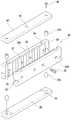
도 2는 본 발명에 의한 화장용구용 심 성형장치를 나타내는 분해 사시도이고,
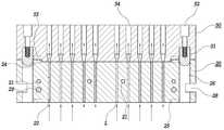
도 3은 본 발명에 의한 화장용구용 심 성형장치에서 심을 성형하는 상태를 나타내는 결합 단면도이며,
도 4는 본 발명에 의한 화장용구용 심 성형장치에서 성형된 심을 케이스에 결합하는 상태를 나타내는 단면도이다.FIG. 1 is an assembled cross-sectional view showing a conventional shoe sole molding apparatus according to the present invention,
Fig. 2 is an exploded perspective view showing a shoemaker for a cosmetic tool according to the present invention,
Fig. 3 is an engaging sectional view showing a state in which a shim is formed in a shim for molding apparatus according to the present invention,
Fig. 4 is a cross-sectional view showing a state in which a shim formed in the shim for molding apparatus according to the present invention is engaged with a case. Fig.
이하, 본 발명의 바람직한 실시예를 첨부된 도면에 의거 더욱 상세하게 설명한다.Hereinafter, preferred embodiments of the present invention will be described in more detail with reference to the accompanying drawings.
도 2 는 본 발명에 의한 화장용구용 심 성형장치를 나타내는 분해 사시도이고, 도 3은 본 발명에 의한 화장용구용 심 성형장치에서 심을 성형하는 상태를 나타내는 결합 단면도이다.FIG. 2 is an exploded perspective view showing a shoelace molding apparatus for a cosmetic implement according to the present invention, and FIG. 3 is an assembled cross-sectional view showing a state in which a shim is molded in a cosmetic molding apparatus for a cosmetic shoe according to the present invention.
본 발명은 심을 성형하는 성형 금형(20)과, 이 성형 금형(20)의 하측에 결합되는 폐쇄판(30) 및 상기 성형 금형(20)의 상측에 결합되는 커버판(40)을 포함한다.The present invention includes a
상기 성형 금형(20)은 서로 마주하며 대칭하여 형성된 한 쌍의 금형판(20a)(20b)으로 이루어지고, 상기 금형판(20a)(20b)은 볼트(21)에 의해 체결되도록 구성된다.The
상기 성형 금형(20)의 내측면에는 중앙에 심(L)을 성형하기 위하여 수직으로 복수 개의 심성형부(22)가 형성되어 결합에 의해 단면이 원형, 사각형, 삼각형 등 어떤 단면형상을 가지는 심(L)을 성형하도록 형성된다.A plurality of
상기 성형 금형(20)의 상부 중앙에는 내부로 유입된 원료를 상기 각 심성형부(12)로 공급하도록 유도하는 원료 유도부(23)가 일정 깊이로 형성됨과 아울러 상기 심성형부(22)의 상단과 연통되도록 구성되어 있다.A
그리고 상기 성형 금형(20)의 상부 및 하부면에는 복수 개의 자석(24)(25)이 삽입된 상태로 결합되어 있고, 양 가장자리에는 폐쇄판(30) 및 커버판(40)이 상기 자석(24)(25)과 함께 정 위치에 결합하도록 결합구멍(26)이 형성되어 있으며, 상기 결합구멍(26)에는 상기 성형 금형(20) 및 폐쇄판(30)과 성형 금형(20) 및 커버판(40)에 걸쳐서 결합되는 결합핀(27a)(27b)이 각각 삽입된다. A plurality of
상기 성형 금형(20)의 양측에는 성형 기계에 결합하기 위한 결합홈(28)이 각각 형성되어 있고, 상기 결합홈(28)의 일측에는 서로 한 쌍의 금형판(20a)(20b)을 정 위치에서 결합이 이루어지도록 센터핀(29)이 양측에 삽입되어 있다.A pair of
상기 폐쇄판(30)은 상기 자석(24)과 대응하는 위치에 자력에 의해 결합이 이루어지도록 역시 자석(31)이 결합되어 있고, 상기 결합구멍(26)과 대응하는 위치에는 결합핀(27a)의 하부가 삽입되도록 록 삽입홈(32)이 각각 형성되어 있다.The
그리고 상기 커버판(40)에는 외부에서 원료를 주입하여 상기 심성형부(22) 내로 공급할 수 있도록 원료 주입구(41)가 대략 중앙에 형성되어 있고, 상기 각 자석(25)과 대응하는 위치에는 자력에 의한 결합이 이루어지도록 자석(42)이 결합되어 있고, 상기 결합구멍(27b)과 대응하는 위치에는 결합핀(27b)의 상부가 삽입되도록 삽입홈(43)이 각각 형성되어 있다.The
상기 폐쇄판(30) 및 커버판(40)에 스크류(33)(44)로 체결된 상기 결합핀(27a)(27b)은 각각 상기 결합구멍(26)에 삽입되어 결합된 상태를 유지하게 된다.The
본 실시예에서는 상기 성형 금형(20)의 상측에 원료 유도부(23)가 형성됨으로써 원료 주입구(41)로 주사기 등에 의해 일정 압력으로 주입된 원료가 상기 원료 유도부(23)을 통하여 분배된 후 각각의 심성형부(22)로 주입되도록 하여 심(L)을 성형하게 되는 것이다.The raw
이와 같이 구성된 본 발명에 의한 화장용구용 심 성형장치는 도 3에 도시한 바와 같이 한 쌍의 금형판(20a)(20b)을 결합한 성형 금형(20), 상기 성형 금형(20)의 하부에 폐쇄판(30)을 결합하고 상부에는 커버판(40)을 결합한 결합체를 성형기계에 결합하고 원료를 주입하여 심(L)을 성형하게 된다.3, a
즉, 상기 커버판(40)에 형성된 원료 주입구(41)에 내부에 원료가 저장된 주사기 등을 이용하여 일정 압력을 가하면서 원료를 주입하면 원료 유도부(23)를 통하여 상부면에 균일하게 원료의 공급이 이루어짐과 아울러 각각의 심성형부(22)로도 원활한 원료의 공급이 이루어지게 되는 것이다.That is, when a raw material is injected while a certain pressure is applied to the raw
이때 상기 성형 금형(20)과 폐쇄판(30), 성형 금형(20)과 커버판(40)은 서로 밀폐된 상태는 아니므로 어느 정도의 미세한 공기 배출이 이루어짐으로써 원료의 주입이 가능하게 되는 것이다.At this time, since the molding die 20, the
그리고 원료의 공급이 완료되면 원료의 공급을 중단하고 일정 시간 응고시켜 상부 및 하부면이 평탄한 심(L)의 성형이 완료되면, 커버판(40)을 성형 금형(20)으로부터 분리하고, 도 4에 도시한 바와 같이 상기 성형 금형(20)의 상부에 케이스 결합부재(50)를 결합하게 되는데, 상기 케이스 결합부재(50)는 결합구멍(26) 내에 결합핀(51)을 삽입하고, 그 외측에서 볼트(52)를 상기 결합핀(51) 체결하면 결합이 완료된다.After the supply of the raw material is completed, the supply of the raw material is stopped, and the
이때에도 상기 케이스 결합부재(50)의 저면에는 자석(24)에 대응하는 위치에 자석(53)을 삽입하여 정위치에 결합 할수 있도록 하는 것이 바람직하다.At this time, it is preferable to insert a
이어서, 상기 케이스 결합부재(50)의 결합이 이루어지면 심성형부(22)와 대응하는 위치에 각각의 화장용 연필 케이스(54)를 삽입하고, 상기 성형 금형(20)의 하부에 결합된 폐쇄판(30)을 분리한 후 심성형부(22)의 하부에 화살표로 도시한 바와 같이 공기의 압력을 가하면 응고된 각각의 심(L)이 상기 각 화장용 연필 케이스(51)의 내측으로 삽입됨으로써 화장용구인 연필의 제조가 완료되는 것이다.When the
이때 상기 연필 케이스(54)는 심(L)이 삽입되는 연필의 선단부를 케이스 결합부재(50)에 결합하는 것이 바람직하며, 필요에 따라 연필 전체를 결합할 수도 있음은 물론이다.In this case, it is preferable that the
20: 성형 금형20a,20b: 금형판
22: 심성형부23: 원료 유도부
30: 폐쇄판40: 커버판
41: 원료 주입구50: 케이스 결합부재
54: 연필 케이스L: 심20: forming
22: heart shape part 23:
30: closing plate 40: cover plate
41: Material inlet 50: Case coupling member
54: pencil case L: core
Claims (1)
Translated fromKorean상기 성형 금형 내의 심성형부에 심이 성형된 후에는 상부의 커버판을 분리하고 내부에 연필 케이스가 내장된 케이스 결합부재를 상기 성형 금형의 상부에 결합하고, 상기 성형 금형의 하부에 결합된 폐쇄판을 분리한 후 하부에서 공기의 압력을 가하여 심성형부 내에 성형된 심을 연필 케이스 내로 배출 삽입하여 결합하는 것을 특징으로 하는 화장용구용 심 성형장치.A molding die in which a pair of mold plates are vertically formed to vertically form a plurality of core forming molds and a raw material guide portion is formed on an upper side thereof to supply a raw material to the core molding portion; And a cover plate on which a raw material injection port is formed so as to supply a raw material to the raw material guiding portion and the core forming portion,
After the core is formed on the core of the molding die, the upper cover plate is separated and a case coupling member having a pencil case built therein is coupled to the upper portion of the molding die, and a closing plate coupled to the lower portion of the molding die And then the air is pressurized from the lower part thereof, and the shim formed in the heart-shaped part is inserted into the pencil case for insertion and coupling.
Priority Applications (1)
| Application Number | Priority Date | Filing Date | Title |
|---|---|---|---|
| KR1020150134418AKR101752971B1 (en) | 2015-09-23 | 2015-09-23 | Lead moulding device for makeup utensils |
Applications Claiming Priority (1)
| Application Number | Priority Date | Filing Date | Title |
|---|---|---|---|
| KR1020150134418AKR101752971B1 (en) | 2015-09-23 | 2015-09-23 | Lead moulding device for makeup utensils |
Publications (2)
| Publication Number | Publication Date |
|---|---|
| KR20170035511A KR20170035511A (en) | 2017-03-31 |
| KR101752971B1true KR101752971B1 (en) | 2017-06-30 |
Family
ID=58501067
Family Applications (1)
| Application Number | Title | Priority Date | Filing Date |
|---|---|---|---|
| KR1020150134418AActiveKR101752971B1 (en) | 2015-09-23 | 2015-09-23 | Lead moulding device for makeup utensils |
Country Status (1)
| Country | Link |
|---|---|
| KR (1) | KR101752971B1 (en) |
Cited By (6)
| Publication number | Priority date | Publication date | Assignee | Title |
|---|---|---|---|---|
| KR102414651B1 (en) | 2021-02-17 | 2022-06-30 | (주)믹스앤매치 | Lead moulding device for makeup utensils |
| KR102414652B1 (en) | 2021-02-17 | 2022-06-30 | (주)믹스앤매치 | Lead moulding device for makeup utensils |
| KR20220144447A (en) | 2021-04-19 | 2022-10-27 | (주)믹스앤매치 | Lead moulding device for makeup utensils |
| KR20220144448A (en) | 2021-04-19 | 2022-10-27 | (주)믹스앤매치 | Lead moulding device for makeup utensils |
| KR102559346B1 (en) | 2022-01-24 | 2023-07-26 | (주)믹스앤매치 | Lead moulding and assembling device for makeup utensils having variable lead length |
| KR20230134004A (en) | 2022-03-10 | 2023-09-20 | (주)믹스앤매치 | A cosmetic pencil lead molding mold and a pencil lead insertion device molded by the molding mold |
Families Citing this family (1)
| Publication number | Priority date | Publication date | Assignee | Title |
|---|---|---|---|---|
| KR102525511B1 (en) | 2021-02-23 | 2023-05-30 | (주)믹스앤매치 | Apparatus for manufacturing cosmetic pencil |
Citations (2)
| Publication number | Priority date | Publication date | Assignee | Title |
|---|---|---|---|---|
| KR200161805Y1 (en) | 1997-04-02 | 1999-12-01 | 김영윤 | Cosmetic Tool Body Molding Assembly Device |
| KR101548887B1 (en)* | 2014-12-11 | 2015-09-01 | 김진길 | Lead moulding device for makeup utensils |
- 2015
- 2015-09-23KRKR1020150134418Apatent/KR101752971B1/enactiveActive
Patent Citations (2)
| Publication number | Priority date | Publication date | Assignee | Title |
|---|---|---|---|---|
| KR200161805Y1 (en) | 1997-04-02 | 1999-12-01 | 김영윤 | Cosmetic Tool Body Molding Assembly Device |
| KR101548887B1 (en)* | 2014-12-11 | 2015-09-01 | 김진길 | Lead moulding device for makeup utensils |
Cited By (7)
| Publication number | Priority date | Publication date | Assignee | Title |
|---|---|---|---|---|
| KR102414651B1 (en) | 2021-02-17 | 2022-06-30 | (주)믹스앤매치 | Lead moulding device for makeup utensils |
| KR102414652B1 (en) | 2021-02-17 | 2022-06-30 | (주)믹스앤매치 | Lead moulding device for makeup utensils |
| KR20220144447A (en) | 2021-04-19 | 2022-10-27 | (주)믹스앤매치 | Lead moulding device for makeup utensils |
| KR20220144448A (en) | 2021-04-19 | 2022-10-27 | (주)믹스앤매치 | Lead moulding device for makeup utensils |
| KR102525512B1 (en) | 2021-04-19 | 2023-05-30 | (주)믹스앤매치 | Lead moulding device for makeup utensils |
| KR102559346B1 (en) | 2022-01-24 | 2023-07-26 | (주)믹스앤매치 | Lead moulding and assembling device for makeup utensils having variable lead length |
| KR20230134004A (en) | 2022-03-10 | 2023-09-20 | (주)믹스앤매치 | A cosmetic pencil lead molding mold and a pencil lead insertion device molded by the molding mold |
Also Published As
| Publication number | Publication date |
|---|---|
| KR20170035511A (en) | 2017-03-31 |
Similar Documents
| Publication | Publication Date | Title |
|---|---|---|
| KR101752971B1 (en) | Lead moulding device for makeup utensils | |
| KR101548887B1 (en) | Lead moulding device for makeup utensils | |
| KR101768801B1 (en) | A moulding for a product with undercut | |
| CN202528399U (en) | A cover forming mold | |
| CN207758055U (en) | Row position structure of a mold | |
| CN209079078U (en) | Valve core housing injection mold | |
| CN205497956U (en) | Bucket injection mold's quick cooling body in washing machine | |
| KR101729852B1 (en) | Apparatus of manufacturing cosmetic pencil | |
| CN207808340U (en) | Plastics Healding box handle mould with buckle type covering plate structure | |
| CN210791865U (en) | Injection mold of plastic shell | |
| CN212352784U (en) | A kind of original injection mold for thin-walled threaded cup | |
| CN208277318U (en) | A kind of injection mold with accessory implantation auxiliary part | |
| KR200453535Y1 (en) | Lipstick cosmetic lower case gripper with improved detachable structure | |
| KR20120003977U (en) | Mold block apparatus for stick type cosmetics manufacture | |
| KR200457710Y1 (en) | Button mold | |
| CN217098638U (en) | Die set | |
| CN211334355U (en) | Mould of folding earphone shell of production neck massager | |
| CN219522894U (en) | Injection mold for storage basket | |
| CN213321399U (en) | Injection mold capable of producing two-piece light guide column | |
| CN216609841U (en) | Injection mold with improved glue inlet structure | |
| CN210791864U (en) | Injection mold of plastic cover body | |
| CN111037806A (en) | Combined mold and thermosetting material manufacturing equipment applying same | |
| GB606972A (en) | Improvements in the moulding of keys for typewriters or calculating machines from thermoplastic material, having inlays of different colour from the surface of the articles | |
| KR102414652B1 (en) | Lead moulding device for makeup utensils | |
| CN211492621U (en) | Hot runner mold |
Legal Events
| Date | Code | Title | Description |
|---|---|---|---|
| A201 | Request for examination | ||
| PA0109 | Patent application | Patent event code:PA01091R01D Comment text:Patent Application Patent event date:20150923 | |
| PA0201 | Request for examination | ||
| PG1501 | Laying open of application | ||
| E902 | Notification of reason for refusal | ||
| PE0902 | Notice of grounds for rejection | Comment text:Notification of reason for refusal Patent event date:20170405 Patent event code:PE09021S01D | |
| E701 | Decision to grant or registration of patent right | ||
| PE0701 | Decision of registration | Patent event code:PE07011S01D Comment text:Decision to Grant Registration Patent event date:20170614 | |
| GRNT | Written decision to grant | ||
| PR0701 | Registration of establishment | Comment text:Registration of Establishment Patent event date:20170626 Patent event code:PR07011E01D | |
| PR1002 | Payment of registration fee | Payment date:20170626 End annual number:3 Start annual number:1 | |
| PG1601 | Publication of registration | ||
| PR1001 | Payment of annual fee | Payment date:20200406 Start annual number:4 End annual number:4 | |
| PR1001 | Payment of annual fee | Payment date:20210407 Start annual number:5 End annual number:5 | |
| PR1001 | Payment of annual fee | Payment date:20220328 Start annual number:6 End annual number:6 | |
| PR1001 | Payment of annual fee | Payment date:20230329 Start annual number:7 End annual number:7 | |
| PR1001 | Payment of annual fee | Payment date:20240327 Start annual number:8 End annual number:8 | |
| PR1001 | Payment of annual fee | Payment date:20250401 Start annual number:9 End annual number:9 |