KR101752670B1 - Refrigerator - Google Patents
RefrigeratorDownload PDFInfo
- Publication number
- KR101752670B1 KR101752670B1KR1020100077596AKR20100077596AKR101752670B1KR 101752670 B1KR101752670 B1KR 101752670B1KR 1020100077596 AKR1020100077596 AKR 1020100077596AKR 20100077596 AKR20100077596 AKR 20100077596AKR 101752670 B1KR101752670 B1KR 101752670B1
- Authority
- KR
- South Korea
- Prior art keywords
- door
- pair
- main body
- refrigerator
- hinge
- Prior art date
- Legal status (The legal status is an assumption and is not a legal conclusion. Google has not performed a legal analysis and makes no representation as to the accuracy of the status listed.)
- Expired - Fee Related
Links
Images


Classifications
- F—MECHANICAL ENGINEERING; LIGHTING; HEATING; WEAPONS; BLASTING
- F25—REFRIGERATION OR COOLING; COMBINED HEATING AND REFRIGERATION SYSTEMS; HEAT PUMP SYSTEMS; MANUFACTURE OR STORAGE OF ICE; LIQUEFACTION SOLIDIFICATION OF GASES
- F25D—REFRIGERATORS; COLD ROOMS; ICE-BOXES; COOLING OR FREEZING APPARATUS NOT OTHERWISE PROVIDED FOR
- F25D23/00—General constructional features
- F25D23/02—Doors; Covers
- F25D23/028—Details
- E—FIXED CONSTRUCTIONS
- E05—LOCKS; KEYS; WINDOW OR DOOR FITTINGS; SAFES
- E05D—HINGES OR SUSPENSION DEVICES FOR DOORS, WINDOWS OR WINGS
- E05D7/00—Hinges or pivots of special construction
- E05D7/0009—Adjustable hinges
- E05D7/0018—Adjustable hinges at the hinge axis
- E05D7/0027—Adjustable hinges at the hinge axis in an axial direction
- E—FIXED CONSTRUCTIONS
- E05—LOCKS; KEYS; WINDOW OR DOOR FITTINGS; SAFES
- E05D—HINGES OR SUSPENSION DEVICES FOR DOORS, WINDOWS OR WINGS
- E05D7/00—Hinges or pivots of special construction
- E05D7/10—Hinges or pivots of special construction to allow easy separation or connection of the parts at the hinge axis
- E05D7/1044—Hinges or pivots of special construction to allow easy separation or connection of the parts at the hinge axis in an axial direction
- F—MECHANICAL ENGINEERING; LIGHTING; HEATING; WEAPONS; BLASTING
- F25—REFRIGERATION OR COOLING; COMBINED HEATING AND REFRIGERATION SYSTEMS; HEAT PUMP SYSTEMS; MANUFACTURE OR STORAGE OF ICE; LIQUEFACTION SOLIDIFICATION OF GASES
- F25D—REFRIGERATORS; COLD ROOMS; ICE-BOXES; COOLING OR FREEZING APPARATUS NOT OTHERWISE PROVIDED FOR
- F25D11/00—Self-contained movable devices, e.g. domestic refrigerators
- F—MECHANICAL ENGINEERING; LIGHTING; HEATING; WEAPONS; BLASTING
- F25—REFRIGERATION OR COOLING; COMBINED HEATING AND REFRIGERATION SYSTEMS; HEAT PUMP SYSTEMS; MANUFACTURE OR STORAGE OF ICE; LIQUEFACTION SOLIDIFICATION OF GASES
- F25D—REFRIGERATORS; COLD ROOMS; ICE-BOXES; COOLING OR FREEZING APPARATUS NOT OTHERWISE PROVIDED FOR
- F25D23/00—General constructional features
- F25D23/02—Doors; Covers
- F—MECHANICAL ENGINEERING; LIGHTING; HEATING; WEAPONS; BLASTING
- F25—REFRIGERATION OR COOLING; COMBINED HEATING AND REFRIGERATION SYSTEMS; HEAT PUMP SYSTEMS; MANUFACTURE OR STORAGE OF ICE; LIQUEFACTION SOLIDIFICATION OF GASES
- F25D—REFRIGERATORS; COLD ROOMS; ICE-BOXES; COOLING OR FREEZING APPARATUS NOT OTHERWISE PROVIDED FOR
- F25D23/00—General constructional features
- F25D23/06—Walls
- F—MECHANICAL ENGINEERING; LIGHTING; HEATING; WEAPONS; BLASTING
- F25—REFRIGERATION OR COOLING; COMBINED HEATING AND REFRIGERATION SYSTEMS; HEAT PUMP SYSTEMS; MANUFACTURE OR STORAGE OF ICE; LIQUEFACTION SOLIDIFICATION OF GASES
- F25D—REFRIGERATORS; COLD ROOMS; ICE-BOXES; COOLING OR FREEZING APPARATUS NOT OTHERWISE PROVIDED FOR
- F25D27/00—Lighting arrangements
- E—FIXED CONSTRUCTIONS
- E05—LOCKS; KEYS; WINDOW OR DOOR FITTINGS; SAFES
- E05Y—INDEXING SCHEME ASSOCIATED WITH SUBCLASSES E05D AND E05F, RELATING TO CONSTRUCTION ELEMENTS, ELECTRIC CONTROL, POWER SUPPLY, POWER SIGNAL OR TRANSMISSION, USER INTERFACES, MOUNTING OR COUPLING, DETAILS, ACCESSORIES, AUXILIARY OPERATIONS NOT OTHERWISE PROVIDED FOR, APPLICATION THEREOF
- E05Y2800/00—Details, accessories and auxiliary operations not otherwise provided for
- E05Y2800/71—Secondary wings, e.g. pass doors
- E—FIXED CONSTRUCTIONS
- E05—LOCKS; KEYS; WINDOW OR DOOR FITTINGS; SAFES
- E05Y—INDEXING SCHEME ASSOCIATED WITH SUBCLASSES E05D AND E05F, RELATING TO CONSTRUCTION ELEMENTS, ELECTRIC CONTROL, POWER SUPPLY, POWER SIGNAL OR TRANSMISSION, USER INTERFACES, MOUNTING OR COUPLING, DETAILS, ACCESSORIES, AUXILIARY OPERATIONS NOT OTHERWISE PROVIDED FOR, APPLICATION THEREOF
- E05Y2900/00—Application of doors, windows, wings or fittings thereof
- E05Y2900/30—Application of doors, windows, wings or fittings thereof for domestic appliances
- E05Y2900/31—Application of doors, windows, wings or fittings thereof for domestic appliances for refrigerators
- F—MECHANICAL ENGINEERING; LIGHTING; HEATING; WEAPONS; BLASTING
- F25—REFRIGERATION OR COOLING; COMBINED HEATING AND REFRIGERATION SYSTEMS; HEAT PUMP SYSTEMS; MANUFACTURE OR STORAGE OF ICE; LIQUEFACTION SOLIDIFICATION OF GASES
- F25D—REFRIGERATORS; COLD ROOMS; ICE-BOXES; COOLING OR FREEZING APPARATUS NOT OTHERWISE PROVIDED FOR
- F25D2323/00—General constructional features not provided for in other groups of this subclass
- F25D2323/02—Details of doors or covers not otherwise covered
- F25D2323/023—Door in door constructions
- F—MECHANICAL ENGINEERING; LIGHTING; HEATING; WEAPONS; BLASTING
- F25—REFRIGERATION OR COOLING; COMBINED HEATING AND REFRIGERATION SYSTEMS; HEAT PUMP SYSTEMS; MANUFACTURE OR STORAGE OF ICE; LIQUEFACTION SOLIDIFICATION OF GASES
- F25D—REFRIGERATORS; COLD ROOMS; ICE-BOXES; COOLING OR FREEZING APPARATUS NOT OTHERWISE PROVIDED FOR
- F25D2323/00—General constructional features not provided for in other groups of this subclass
- F25D2323/02—Details of doors or covers not otherwise covered
- F25D2323/024—Door hinges
Landscapes
- Engineering & Computer Science (AREA)
- Mechanical Engineering (AREA)
- Chemical & Material Sciences (AREA)
- Combustion & Propulsion (AREA)
- Physics & Mathematics (AREA)
- Thermal Sciences (AREA)
- General Engineering & Computer Science (AREA)
- Refrigerator Housings (AREA)
Abstract
Translated fromKoreanDescription
Translated fromKorean본 발명은 본체에 마련된 저장실을 개폐하는 도어를 갖춘 냉장고에 관한 것이다.The present invention relates to a refrigerator having a door that opens and closes a storage room provided in the main body.
일반적으로 냉장고는 내부에 냉동 사이클 구성요소들을 포함하여 냉동사이클의 증발기에서 발생한 냉기로 내부에 저장된 저장물을 냉동 또는 냉장 저장할 수 있도록 한 장치이다.Generally, a refrigerator includes refrigeration cycle components therein, and is a device capable of refrigerating or storing refrigerant stored in the refrigerant generated in an evaporator of a refrigeration cycle.
이러한 냉장고는 음식물 등의 저장물이 저장되는 저장실이 마련된 본체와, 저장실을 개폐하는 도어를 포함한다. 도어는 본체의 일측에 그 일측단이 회전가능하게 설치되어 좌우 방향으로 회전하며 저장실을 개폐한다.Such a refrigerator includes a main body provided with a storage room for storing stored food or the like, and a door for opening and closing the storage room. One side of the door is rotatably installed at one side of the main body, and rotates in the left and right direction to open and close the storage chamber.
또한 근래 이러한 냉장고 중에는 도어를 개방하지 않고도 저장실 내부의 저장물을 인출할 수 있도록 도어에 개구가 마련되고 개구에는 개구를 개폐하는 보조 도어가 설치되어 있는 냉장고가 있다.In recent years, there has been a refrigerator in which an opening is provided in the door so as to draw out stored contents in the storage room without opening the door, and an auxiliary door is provided in the opening to open and close the opening.
본 발명의 일 측면은 보다 간편하게 도어에 손잡이를 설치할 수 있는 냉장고를 제공하기 위한 것이다.One aspect of the present invention is to provide a refrigerator that can be easily attached to a door.
본 발명의 일 측면에 따른 냉장고는 저장실이 마련된 본체와, 저장실을 개폐하는 도어와, 도어의 전면을 형성하는 도어 전면패널과, 도어 전면패널의 측단을 지지하는 도어 트림과, 도어트림으로부터 측방으로 일체로 연장되는 손잡이를 포함한다.A refrigerator according to one aspect of the present invention includes a main body having a storage chamber, a door for opening and closing the storage chamber, a door front panel for forming a front surface of the door, a door trim for supporting a side end of the door front panel, And includes an integrally extending handle.
또한 도어의 일측면을 형성하는 제 1 도어 측면프레임과, 제 1 도어 측면프레임에 전방 및 측방을 향하여 개방되도록 단차지게 마련된 손잡이홈을 더 포함하며, 손잡이는 손잡이홈을 덮도록 연장된다.The door further includes a first door side frame forming one side surface of the door and a handle groove provided so as to be stepped to be opened forward and laterally to the first door side frame, and the handle extends to cover the handle groove.
또한 도어 트림은 오목 형성되어 도어 전면패널의 일측단을 지지하는 패널 지지부를 포함한다.Further, the door trim includes a panel supporting portion which is formed in a concave shape to support one end of the door front panel.
또한 도어 트림의 설치를 위해 제 1 도어 측면프레임에 오목하게 마련된 트림 설치홈과, 손잡이에 마련되어 트림 설치홈에 삽입 지지되는 트림 설치부를 더 포함한다.A trim mounting groove recessed in the first door side frame for mounting the door trim, and a trim mounting portion provided in the handle and inserted and supported in the trim mounting groove.
또한 도어는 동작 상태가 표현되는 디스플레이 유닛과, 제 1 도어 측면프레임에 인접하게 배치되어 디스플레이 유닛이 수용되는 디스플레이 수용부가 마련된 디스플레이 프레임을 더 포함한다.Further, the door further includes a display unit in which an operating state is expressed, and a display frame disposed adjacent to the first door side frame and provided with a display accommodating portion in which the display unit is accommodated.
또한 도어는 제 1 도어 측면프레임 및 제 2 도어 측면프레임의 상단 및 하단을 덮는 상부 도어캡 및 하부 도어캡을 더 포함하며, 상부 도어캡에는 디스플레이 유닛이 상부 도어캡을 관통하여 디스플레이 수용부로 삽입될 수 있도록 하는 디스플레이 삽입공이 마련된다.Further, the door further includes an upper door cap and a lower door cap covering the upper and lower ends of the first door side frame and the second door side frame, wherein the display unit is inserted into the display accommodation portion through the upper door cap A display inserting hole is provided.
또한 손잡이는 투명재질로 형성되며, 손잡이에는 정보 표시를 위한 디스플레이부가 패터닝을 통해 형성된다.Further, the handle is formed of a transparent material, and a display portion for information display is formed on the handle through patterning.
또한 손잡이는 손잡이홈의 전방측을 전체적으로 덮는 제 1 손잡이부와, 손잡이홈의 전방측 일부를 제한적으로 덮는 제 2 손잡이부를 포함한다.Further, the handle includes a first handle portion that covers the front side of the handle groove as a whole, and a second handle portion that restrictively covers a part of the front side of the handle groove.
또한 손잡이는 투명재질로 형성되며, 금속재질로 형성되어 손잡이의 선단을 덮도록 설치되는 손잡이 커버를 더 포함한다.Further, the handle is formed of a transparent material, and further includes a handle cover formed of a metal material and installed to cover the tip of the handle.
또한 손잡이는 도어의 전면과 평행하게 연장된다.The handle also extends parallel to the front of the door.
또한 장식을 위해 도어 전면패널의 후면에 배치되는 장식유닛을 더 포함하며, 장식유닛은 광을 반사 또는 방사하는 복수의 장식부재와, 복수의 장식부재가 일정 형태를 이룬 상태로 고정 설치되도록 하는 고정플레이트를 포함한다.The decorative unit further includes a decorative member arranged on the rear surface of the door front panel for decorating. The decorative unit includes a plurality of decorative members reflecting or radiating light, a plurality of decorative members fixed and fixed in a predetermined form, Plate.
또한 본 발명의 일 측면에 따른 냉장고는 격벽에 의해 냉동실과 냉장실이 좌우로 구획되게 마련된 본체와, 냉동실과 냉장실을 각각 개폐하는 냉동실 도어 및 냉장실 도어와, 냉동실 도어 및 냉장실 도어의 전면을 각각 형성하는 한 쌍의 도어 전면패널과, 냉동실 도어 및 냉장실 도어에 서로 대향되게 마련되어 한 쌍의 도어 전면패널의 측단을 각각 지지하는 한 쌍의 도어 트림과, 한 쌍의 도어 트림으로부터 측방으로 일체로 연장되어 서로 대항되는 한 쌍의 손잡이를 포함한다.According to an aspect of the present invention, there is provided a refrigerator comprising: a body having a freezing compartment and a refrigerating compartment separated from each other by partition walls; a freezing compartment door and a refrigerating compartment door for opening and closing the freezing compartment and the refrigerating compartment, respectively; A pair of door front panels, a pair of door trams opposed to each other in the freezing compartment door and the refrigerating compartment door to respectively support the side ends of the pair of door front panels, And includes a pair of opposing knobs.
상술한 바와 같이 도어에 마련된 손잡이는 도어 트림으로부터 일체로 연장형성되므로, 도어 트림을 도어에 설치함에 따라 도어에 손잡이가 간편하게 설치된다.As described above, since the handle provided on the door extends integrally from the door trim, the handle can be easily installed on the door as the door trim is installed on the door.
도 1은 본 발명의 일 실시예에 따른 냉장고의 사시도이다.
도 2는 본 발명의 일 실시예에 따른 냉장고의 분해 사시도이다.
도 3은 본 발명의 일 실시예에 따른 냉장고에 적용된 상부 힌지모듈의 설치 상태를 보인 사시도이다.
도 4는 본 발명의 일 실시예에 따른 냉장고에 적용된 하부 힌지모듈의 설치상태를 보인 사시도이다.
도 5 내지 도 7는 본 발명의 일 실시예에 따른 냉장고에 적용된 상부 힌지모듈의 설치 상태를 보인 도면이다.
도 8은 본 발명의 일 실시예에 따른 냉장고에 적용된 본체의 분해사시도이다.
도 9는 본 발명의 일 실시예에 따른 냉장고에 적용된 하부 힌지모듈의 분해사시도이다.
도 10과 도9는 본 발명의 일 실시예에 따른 냉장고에 적용된 하부 힌지모듈을 통한 도어 높이 조절방법을 보인 단면도이다.
도 12는 본 발명의 일 실시예에 따른 냉장고에 적용된 하부 힌지모듈의 단면도이다.
도 13은 본 발명의 다른 하나의 실시예에 따른 냉장고에 적용된 하부 힌지모듈의 단면도이다.
도 14는 본 발명의 일 실시예에 따른 냉장고에 적용된 도어의 분해사시도이다.
도 15는 본 발명의 일 실시예에 따른 냉장고에 적용된 손잡이 및 도어 커버의 설치 상태를 보인 분해사시도이다.
도 16은 본 발명의 또 다른 하나의 실시예에 따른 냉장고에 적용된 투명 디스플레이 유닛의 설치상태를 보인 부분 확대 사시도이다.
도 17은 본 발명의 일 실시예에 따른 냉장고에 적용된 보조 도어의 사시도이다.
도 18은 본 발명의 일 실시예에 따른 냉장고에 적용된 보조 도어 및 락킹장치의 설치 상태를 보인 측단면도이다.
도 19는 본 발명의 일 실시예에 따른 냉장고에 적용된 락킹장치의 분해사시도이다.
도 20과 도 21은 본 발명의 일 실시예에 따른 냉장고에 적용된 락킹장치의 동작 상태를 보인 사시도이다.
도 22는 본 발명의 일 실시예에 따른 냉장고에 적용된 도어 선반의 사시도이다.
도 23은 종래의 냉장고에 적용된 상부 힌지모듈의 설치 상태를 보인 사시도이다.
도 24는 종래의 냉장고에 적용된 하부 힌지모듈의 설치 상태를 보인 사시도이다.
도 25는 종래의 냉장고에 적용된 보조 도어 및 락킹장치의 설치 상태를 보인 측단면도이다.1 is a perspective view of a refrigerator according to an embodiment of the present invention.
2 is an exploded perspective view of a refrigerator according to an embodiment of the present invention.
3 is a perspective view showing an installation state of an upper hinge module applied to a refrigerator according to an embodiment of the present invention.
FIG. 4 is a perspective view illustrating the installation of a lower hinge module applied to a refrigerator according to an embodiment of the present invention.
5 to 7 are views showing an installation state of an upper hinge module applied to a refrigerator according to an embodiment of the present invention.
8 is an exploded perspective view of a main body applied to a refrigerator according to an embodiment of the present invention.
9 is an exploded perspective view of a lower hinge module applied to a refrigerator according to an embodiment of the present invention.
10 and 9 are cross-sectional views illustrating a door height adjusting method using a lower hinge module applied to a refrigerator according to an embodiment of the present invention.
12 is a sectional view of a lower hinge module applied to a refrigerator according to an embodiment of the present invention.
13 is a sectional view of a lower hinge module applied to a refrigerator according to another embodiment of the present invention.
14 is an exploded perspective view of a door applied to a refrigerator according to an embodiment of the present invention.
FIG. 15 is an exploded perspective view showing a state where a handle and a door cover are applied to a refrigerator according to an embodiment of the present invention.
16 is a partially enlarged perspective view showing the installation state of the transparent display unit applied to the refrigerator according to another embodiment of the present invention.
17 is a perspective view of an auxiliary door applied to a refrigerator according to an embodiment of the present invention.
18 is a side cross-sectional view showing the installed state of the auxiliary door and the locking device applied to the refrigerator according to the embodiment of the present invention.
19 is an exploded perspective view of a locking device applied to a refrigerator according to an embodiment of the present invention.
20 and 21 are perspective views showing an operating state of a locking device applied to a refrigerator according to an embodiment of the present invention.
22 is a perspective view of a door lathe applied to a refrigerator according to an embodiment of the present invention.
23 is a perspective view showing an installation state of an upper hinge module applied to a conventional refrigerator.
24 is a perspective view showing the installation state of a lower hinge module applied to a conventional refrigerator.
25 is a side cross-sectional view showing the installed state of the auxiliary door and the locking device applied to the conventional refrigerator.
이하에서는 본 발명에 따른 일 실시예에 따른 냉장고를 도면을 참조하여 상세히 설명한다.Hereinafter, a refrigerator according to an embodiment of the present invention will be described in detail with reference to the drawings.
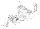
도 1, 2에 도시한 바와 같이 본 발명에 따른 냉장고는 그 외관을 형성하며 내부에 저장물이 저장되는 저장실(111F, 111R)이 마련된 본체(10)와, 일 측단이 본체(10)에 회전 가능하게 설치되어 회전하며 저장실(111F, 111R)을 개폐하는 도어(20)를 포함한다.1 and 2, the refrigerator according to the present invention includes a
본체(10) 내에는 도 8에 도시한 바와 같이 냉매를 압축하는 압축기(12)와, 냉매가 본체(10) 외부의 공기와 열교환하며 냉각되도록 하는 응축기(12)와, 냉매가 감압 팽창되도록 하는 팽창 밸브(미도시)와, 냉매가 증발하며 저장실(111F, 111R) 내부의 공기로부터 열을 흡수하여 냉기를 발생시키는 증발기(미도시) 등의 냉동사이클 구성 요소들이 설치되어, 증발기에서 발생한 냉기가 저장실(111F, 111R)로 공급되도록 함으로써 저장실(111F, 111R) 내에 저장된 저장물이 저온 상태로 유지된다.As shown in Fig. 8, the
본체(10)의 하부 후방측에는 압축기(11), 응축기(12) 및 팽창밸브 등의 구성이 설치되는 기계실이 마련되며, 저장실(111F, 111R)의 후방측에는 증발기가 배치되는 냉각실(미도시)이 마련된다.A machine room in which a structure of a
저장실(111F, 111R)은 좌우로 구획되어 일측이 저장물을 냉동 저장하는 냉동실(111F)을 형성하며 타측이 저장물을 냉장 저장하는 냉장실(111R)을 형성한다. 도어(20)는 냉동실(111F)을 개폐하는 냉동실 도어(20F)와 냉장실(111R)을 개폐하는 냉장실 도어(20R)를 포함한다.The
본체(10)는 그 외부 형태를 형성하는 외상(100)과, 외상(100) 내에 배치되며 상술한 저장실(111F, 111R)을 형성하는 내상(110)을 포함하며, 외상(100)과 내상(110) 사이의 공간에는 단열부재가 채워진다. 외상(100)은 내구성 등을 고려하여 대부분의 부분이 금속재질로 형성되며, 내상(110)은 단열성 및 제조 편이성을 고려하여 수지재질로 형성된다.The
본체(10)의 외부 형태를 형성하는 외상(100)은 금속재질의 판재를 U자 형태로 밴딩하여 형성되며 외상(100)의 하면 및 양 측면을 일체로 형성하는 메인프레임(101)과, 메인프레임(101)의 상단에 설치되어 외상의 상면을 형성하는 상면프레임(102, 103)과, 메인프레임(101)의 후방측을 덮도록 설치되어 외상(100)의 후면을 형성하는 후면프레임(105)과, 메인프레임(101)의 하부 후방측에 설치되어 상술한 기계실을 형성하는 기계실 프레임(106)과 기계실의 하면을 형성하는 하면프레임(107) 등을 포함한다.The
내상(110)은 수지재질로 형성되며 전방측으로 개방되어 저장실(111F, 111R)이 형성되고, 저장실(111F, 111R)에는 상하로 연장되어 저장실(111F, 111R)을 좌우로 구획하는 격벽(112)이 마련되어 격벽(112)에 의해 구획된 저장실(111F, 111R)의 일측이 냉동실(111F)을 형성하고 타측이 냉장실(111R)을 형성한다.The
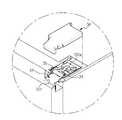
도 2에 도시한 바와 같이 냉동실 도어(20F) 및 냉장실 도어(20R)가 본체(10)에 회전 가능하게 설치될 수 있도록 하기 위해 본체(10)의 상부 양측에는 두 도어(20)의 일측 상단이 본체(10)의 상부에 각각 회전 가능하게 설치될 수 있도록 하는 상부 힌지모듈(30)가 설치되어 있으며, 본체(10)의 하부 양측에는 두 도어(20)의 일측 하단이 본체(10)의 하부에 각각 회전 가능하게 설치될 수 있도록 하는 하부 힌지모듈(40)이 설치되어 있다.As shown in FIG. 2, at one side of the upper portion of the
두 도어(20)의 일측 상단에는 상부 힌지홈(20a)이 오목하게 마련되고 두 도어(20)의 일측 하단에는 하부 힌지홈(20b)이 오목하게 마련되어, 도어(20)의 상단 일측이 상부 힌지(31a) 및 상부 힌지홈(20a)을 통해 본체(10)에 회전 가능하게 설치되고 도어(20)의 하단 일측이 하부 힌지(43) 및 하부 힌지홈(20b)을 통해 본체(10)에 회전 가능하게 설치되어 두 도어(20)가 본체(10)에 회전 가능하게 설치된다.An
따라서, 도 4에 도시한 바와 같이 두 하부 힌지모듈(40)은 그 후단이 본체(10)의 외상(100)의 외부 하면에 설치되고 그 전단이 두 도어(20)의 하측에 각각 배치되어 도어(20)의 하부 힌지홈(20b)에 설치된 하부 힌지(43)를 통해 두 도어(20)의 하중을 지지함과 동시에 두 도어(20)의 하단 일측을 회전 가능하게 지지하며, 도 3에 도시한 바와 같이 두 상부 힌지모듈(30)은 두 도어(20)의 상측에 배치되어 도어(20)의 상부 힌지홈(20a)에 설치된 상부 힌지(31a)를 통해 두 도어(20)가 직립한 상태로 회전하며 저장실(111F, 111R)을 개폐할 수 있도록 한다.4, the rear ends of the two
종래에는 본체 외상의 양측면과 하면은 별도의 부재로 형성되어 있어, 외상의 양측면과 하면을 연결하는 부위를 고정하기 위한 고정부재가 외상 양측면과 하면이 만나는 곳 외측에 전체적으로 설치되어야 하였는데 이에 의해 외관 품질의 저하가 발생한다.A fixing member for fixing a portion connecting both side surfaces of the external surface and the lower surface has to be installed entirely outside the area where both the external surface and the bottom surface meet, .
그러나, 본 실시예에서는 메인프레임(101)이 본체(10)의 외상(100) 하면 및 양측면을 일체로 형성하여 외상(100) 하면과 양측면 사이에는 연결부가 형성되지 않으므로 별도의 부재 설치에 의한 외관 품질의 저하는 발생하지 않는다.However, in the present embodiment, since the
본 실시예에서 하부 힌지모듈(40)이 설치되는 부위의 강도를 보강하여 하부 힌지모듈(40)이 본체(10)의 하면에 안정적으로 설치될 수 있도록 하기 위해 외상(100)의 내부 하면에는 하부 보강프레임(108, 도 8 참조)이 설치된다.In order to reinforce the strength of the portion where the
상부 힌지모듈(30)은 도 5와 도 6에 도시한 바와 같이 도어(20)의 상단이 회전 가능하게 설치되는 상부 힌지브래킷(31)과, 본체(10)의 상면에 고정되어 상부 힌지브래킷(31)의 후단이 본체(10)에 고정 설치되도록 하는 고정브래킷(32)과, 고정브래킷(32)에 탈착 및 회전 가능하게 설치되어 그 회전각도에 따라 선택적으로 상부 힌지브래킷(31)을 고정브래킷(32)으로 가압 지지하는 고정레버(33), 상부 힌지브래킷(31), 고정브래킷(32) 및 고정레버(33) 등의 상측을 덮어 가리는 힌지커버(34)를 포함한다.5 and 6, the
상부 힌지모듈(30)과 도어(20) 사이에는 냉장고의 운송 중 발생할 수 있는 진동에 의해 도어(20)가 유동하는 것을 방지하기 위해 도 3에 도시한 바와 같이 유동방지부재(70)가 설치된다. 유동방지부재(70)는 상부 힌지(31a)에 분리 가능하게 설치되어 도어(20) 상면과 상부 힌지브래킷(31)의 사이를 지지하도록 설치되어 유동을 방지한다.A flow
이러한 유동방지부재(70)는 각각 호 형상으로 형성되어 상부 힌지(31a)의 양측에 지지되는 한 쌍의 힌지 지지부(71)와, 두 힌지 지지부(71)의 일측을 서로 연결하며 호 형상으로 형성되어 두 힌지 지지부(71)가 상부 힌지에 탄성지지되도록 하는 탄성부(72)와, 두 힌지 지지부(71)의 타측에 각각 마련되어 두 힌지 지지부(71)의 내측으로 상부 힌지(31a)가 삽입될 수 있도록 안내하는 삽입 가이드(73)를 포함한다.Each of the
따라서 냉장고를 운송하는 중에는 유동방지부재(70)를 상부 힌지(31a)에 설치하여 유동방지부재(70)에 의해 상부 힌지브래킷(31)과 도어(20)가 서로 지지되도록 하여 도어(20)의 유동을 방지하다가 냉장고의 설치가 완료된 후에는 유동방지부재(70)를 상부 힌지(31a)로부터 분리하여 도어(20)가 원활하게 회전할 수 있게 한다.Therefore, while the refrigerator is being transported, the
고정브래킷(32)은 그 후단으로부터 상측으로 연장되어 상부 힌지브래킷(31)의 후단이 지지되는 제 1 지지대(321)와, 그 양측단으로부터 상측으로 연장되어 고정레버(33)가 회전 가능하게 설치되는 한 쌍의 제 2 지지대(322)를 포함한다. 제 1 지지대(321)에는 상부 힌지브래킷(31)의 후단이 삽입 지지되는 지지홀(321a)이 마련되며, 제 2 지지대(322)에는 고정레버(33)의 양단이 회전 가능하게 설치되는 레버 설치홈(322a)이 마련된다.The fixing
상부 힌지브래킷(31)은 그 후단이 고정브래킷(32)을 통해 본체(10)의 상면에 고정되고 그 전단이 본체(10)의 전방측으로 돌출되도록 설치된다. 또한 상부 힌지브래킷(31)은 그 전단으로부터 하측으로 돌출되어 도어(20)의 상단에 회전가능하게 설치되는 상부 힌지(31a)와, 상부 힌지브래킷(31)의 후단으로부터 돌출되어 지지홀(321a)에 삽입 지지되는 지지돌기(31b)를 포함한다.The rear end of the
또한 본 실시예에서 상부 힌지모듈(30)은 상부 힌지브래킷(31)을 좌우 방향으로 이동시켜 도어(20) 상단을 좌우 방향으로 일정 거리 이내에서 조절할 수 있도록 되어 있는데, 이를 위해 상부 힌지브래킷(31)의 일측에는 두 제 2 지지대(322) 중 하나와 나란하게 배치되는 조절 가이드(31c)가 마련되며, 제 2 지지대(322)에는 회전하며 상부 힌지브래킷(31)을 이동시키는 조절나사(35)가 설치된다. 따라서, 조절나사(35)를 회전시켜 제 2 지지대(322)와 조절 가이드(31c) 사이의 간격이 변경되도록 함으로써, 상부 힌지브래킷(31)을 좌우 방향으로 이동시킬 수 있으며, 상부 힌지브래킷(31)을 이동시키면 상부 힌지브래킷(31)을 통해 본체(10)에 회전 가능하게 설치되어 있는 도어(20)의 상단도 좌우 방향으로 이동하게 된다.In this embodiment, the
고정레버(33)는 도 7에 도시한 바와 같이 전단측에 마련되어 고정레버(33)의 회전 각도에 따라 상부 힌지브래킷(31)을 가압하여 고정브래킷(32)에 밀착시키는 가압부(33a)와, 그 후단측에 마련되어 작업자가 용이하게 고정레버(33)를 회전시킬 수 있도록 하는 레버부(33b)와, 그 양측에 각각 마련되어 고정레버(33)가 고정브래킷(32)에 회전 가능하게 설치될 수 있도록 하는 한 쌍의 힌지돌기(33c)를 포함한다.The fixing
이때, 상술한 바와 같이 상부 힌지모듈(30)은 상부 힌지브래킷(31), 고정브래킷(32), 고정레버(33), 힌지커버(34) 등의 구성을 포함하므로, 불가피하게 상하 방향으로 일정 두께를 갖도록 형성될 수 밖에 없는데, 이와 같이 일정 두께를 갖는 상부 힌지모듈(30)을 본체(10)의 상면에 그대로 설치할 경우, 상부 힌지모듈(30)은 도 23에 도시한 바와 같이 본체(10)의 상측으로 돌출되며, 도어(20')는 본체(10') 상측으로 돌출된 상부 힌지모듈(30')을 가리기 위해 그 상단이 상부 힌지모듈(30')의 상면과 대응하는 높이를 갖도록 형성되는데, 이와 같이 도어(20')를 형성할 경우, 냉장고의 높이는 상대적으로 높은 도어(20')에 의해 결정되고, 본체(10')의 높이는 도어(20')에 비해 낮게 형성되므로, 도어(20'), 즉, 냉장고의 높이에 비해 본체(10')의 높이가 낮아지며 그에 따라 본체(10') 내에 형성되는 저장실의 용적 또한 작게 형성될 수 밖에 없다.Since the
따라서, 본 실시예에서 본체(10)의 상면에는 도 5 및 도 6에 도시한 바와 같이 상술한 상부 힌지모듈(30)의 후단이 수용되는 본체 힌지수용부(102a)가 마련된다.되며, 도어(20)에는 상부 힌지모듈(30)의 전단이 수용 및 설치되는 도어 힌지수용부(20f)가 마련된다.Therefore, in the present embodiment, the
본체 힌지수용부(102a)는 상부 힌지모듈(30)의 두께와 대응하는 깊이로 오목형성되며, 그 전방측 단부는 상부 힌지모듈(30)의 전단이 본체(10)의 전방측으로 돌출될 수 있도록 하기 위해 개방되어 있다. 또한 본체 힌지수용부(102a) 내에는 본체 힌지수용부(102a)의 측면을 따라 이격 형성되는 지지리브(102c)가 마련되어 지지리브(102c)에 의해 힌지커버(34)의 측면 내측이 지지되도록 되어 있다.The main
도어 힌지수용부(20f)는 도어(20)의 후면 일측에 오목하게 마련되어 상부 힌지모듈(30)의 전단을 수용할 수 있도록 되어 있으며, 그 내측 하면에 상술한 상부 힌지홈(20a)이 마련된다.The door hinge
상술한 바와 같이 본체(10)의 상면에 본체 힌지수용부(102a)가 마련되어 있으므로 상부 힌지모듈(30)의 후단을 본체 힌지수용부(102a)에 설치하고 상부 힌지모듈)_의 전단을 도어 힌지수용부(20f)에 설치하면 상부 힌지모듈(30)의 후단이 본체(10)의 상면에 매립 설치되고 상부 힌지모듈(30)의 전단이 도어 힌지수용부(20f)에 수용되므로, 본체(10)의 상면 높이를 도어(20) 상면 높이와 대응하도록 높게 형성할 수 있다.Since the main
본 실시예에서 상부 힌지모듈(30)의 상면, 즉 힌지커버(34)의 상면이 도어(20)의 상단 및 본체(10) 상면과 실질적으로 동일한 높이에 위치하게 되어, 상부 힌지모듈(30)이 본체(10)의 상측으로 돌출될 경우에 발생할 수 있는 냉장고의 높이 상승이나 냉장고의 외관 품질 저하는 예방된다.The upper surface of the
또한, 본 실시예에서와 같이 상부 힌지모듈(30)을 본체(10)의 상면에 매립 설치하면 본체(10)의 상면 높이를 상부 힌지모듈(30) 상면의 높이 및 도어(20) 상단의 높이와 동일하게 형성할 수 있어, 일정 높이를 갖는 냉장고에 보다 높은 높이를 갖는 본체(10)를 적용할 수 있으며, 그에 따라 본체(10) 내에 보다 넓은 저장실(111F, 111R) 용적을 확보할 수 있다.When the
냉장고에는 냉장실(111R) 및 냉동실(111F)이 좌우측에 나란히 마련되어 냉장실 도어(20R) 및 냉동실 도어(20F)의 일측이 본체(10)의 양측에 각각 회전 가능하게 설치되므로, 상부 힌지모듈(30)은 한 쌍이 구비되며 본체 힌지수용부(102a)는 본체(10)의 상면 양측에 각각 마련되어 두 도어(20)의 일측 상단을 각각 회전 가능하게 지지할 수 있도록 되어 있다.The refrigerator includes a
상기의 도 8에서 외상(100)에 대해 언급한 바와 같이 외상(100)은 U자 형태의 메인프레임(101)과, 상면프레임(102, 103)을 포함하도록 되어 있는데, 이는 상술한 외상(100)의 상면에 본체 힌지수용부(102a)가 용이하게 형성될 수 있도록 하기 위한 것이다.8, the
즉, 종래의 냉장고에 적용되는 외상은 금속재질의 판재를 역 U자 형상으로 밴딩하여 외상의 상면과 양측면을 이루는 메인프레임을 포함하는데, 상부 힌지모듈을 본체의 상면에 매립 설치하기 위해서는 상대적으로 변형시키기 어려운 재질인 금속재질로 이루어진 메인프레임의 상면 일부를 변형시켜 본체 힌지수용부를 형성하여야만 한다. 따라서 종래의 냉장고의 경우 도 23에 도시한 바와 같이 변형시키기 어려운 냉장고 상면을 변형시켜 본체 힌지수용부를 형성하기 보다는 상부 힌지모듈(30')을 본체(10')의 상측으로 돌출되어 있는 형태로 설치하였다.That is, the trauma applied to the conventional refrigerator includes a main frame which is formed by bending a metal plate in an inverted U shape to form an upper surface and both side surfaces of the trauma. In order to embed the upper hinge module on the upper surface of the main body, The main hinge accommodating portion must be formed by deforming a part of the upper surface of the main frame made of a metal material which is difficult to make. Therefore, in the conventional refrigerator, as shown in FIG. 23, the upper hinge module 30 'is protruded to the upper side of the main body 10' rather than forming the main hinge accommodating portion by deforming the upper surface of the refrigerator, Respectively.
그러나 본 실시예에서와 같이, 외상(100)의 상면을 형성하는 상면프레임(102, 103)이 메인프레임(101)과 별도의 부재로 형성되도록 하면, 본체 힌지수용부(102a)가 마련된 상면프레임(102, 103)을 메인프레임(101)과는 별도로 제조한 후, 금속재질의 판재를 U자 형상으로 밴딩하여 형성된 메인프레임(101)에 설치함으로써 본체 힌지수용부(102a)가 마련된 외상(100)이 간단하게 제조된다.However, as in the present embodiment, when the upper surface frames 102 and 103 forming the upper surface of the
본 실시예에서 상면프레임(102, 103)은 양측에 본체 힌지수용부(102a)가 각각 마련되어 외상(100)의 상면 전방측을 형성하는 제 1 상면프레임(102)과, 제 1 상면프레임(102)의 후방측에 배치되어 외상(100)의 상면 후방측을 형성하여 제 1 상면프레임(102)과 함께 외상(100)의 상면, 즉 본체(10)의 상면을 형성하는 제 2 상면프레임(103)을 포함한다. 이때, 제 1 상면프레임(102)의 경우 본체 힌지수용부(102a)를 용이하게 성형할 수 있도록 수지재질로 형성되며, 제 2 상면프레임(103)의 경우 충분한 강도를 갖도록 금속재질로 형성된다.The
수지재질은 사출금형 등을 통해 일정 형태로 성형하기 용이한 재질일 뿐만 아니라 금속재질 등에 비해 상대적으로 단열성이 우수한 재질이므로, 상기와 같이 본체(10)의 상면에 본체 힌지수용부(102a)를 형성하는 과정에서 본체 힌지수용부(102a)가 마련된 본체(10) 상단의 일부 부위의 두께가 부분적으로 얇아지더라도 수지재질로 형성된 제 1 상면프레임(102)이 배치된 부위의 단열능력은 금속재질로 형성된 제 2 상면프레임(103)이 배치된 부위와 유사한 수준으로 유지될 수 있다.Since the resin material is a material that is easy to mold in a certain shape through an injection mold or the like and is relatively more heat-insulating than metal materials, the main
본 실시예에서 상면프레임(102, 103)은 서로 별개로 제조된 제 1 상면프레임(102)과 제 2 상면프레임(103)으로 이루어져 있으나 이에 한정되는 것은 아니며 상면프레임이 하나의 부재로 이루어지도록 하는 것도 가능하다.In this embodiment, the
상술한 바와 같이 수지재질로 형성된 제 1 상면프레임(102)에 본체 힌지수용부(102a)를 마련하여 상부 힌지모듈(30)을 설치하면 제 1 상면프레임(102)에는 상부 힌지모듈(30)을 통해 도어(20)의 하중이 걸리게 될 수 있다. 따라서, 제 1 상면프레임(102)의 하측에는 수지재질로 형성되어 있는 제 1 상면프레임(102)의 강도를 보강하기 위해 금속재질로 형성된 상부 보강프레임(104)이 배치된다. 상부 보강프레임(104)은 제 1 상면프레임(102)의 본체 힌지수용부(102a) 하면과 대응하도록 그 양측이 하측으로 절곡되어 있다. 본 실시예에서 본체 힌지수용부(102a)에는 관통공(102b)이 마련되어 고정브래킷(32)이 관통공(102b)을 통해 상부 보강프레임(104)에 직접 고정 설치되도록 되어 있다. 이와 같이 상부 보강프레임(104)에 고정브래킷(32)이 설치되도록 하면, 도어(20)의 하중은 수지재질의 제 1 상면프레임(102)이 아닌 금속재질의 상부 보강프레임(104)을 통해 지지되므로, 도어(20)가 본체(10)에 설치되어 있는 상태는 안정적으로 유지될 수 있다.When the main
또한, 상부 보강프레임(104)은 메인프레임(101)의 양측면이 서로 지지될 수 있도록 하는 역할도 수행하는데, 이를 위해 메인프레임(101)의 내부 양측면 상부에는 상부 보강프레임(104)의 양단이 각각 지지되는 프레임 지지부(101a)가 마련되며, 상부 보강프레임(104)의 양단에는 하측으로 연장되어 프레임 지지부(101a)에 삽입되어 걸리는 삽입부(104b)가 마련된다.The upper reinforcing
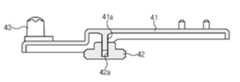
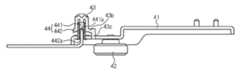
하부 힌지모듈(40)은 도 9와 도 10에 도시한 바와 같이 그 후단은 외상(100)의 하면에 설치되고 그 전단은 본체(10)의 전방측으로 돌출되어 본체(10) 전방측에 설치된 도어(20)의 하측으로 연장되는 하부 힌지브래킷(41)과, 하부 힌지브래킷에 설치되며 하부 힌지브래킷의 하측에 배치되어 하부 힌지브래킷 및 하부 힌지브래킷이 설치된 본체가 지면에 지지되도록 하는 레그(42)와, 하부 힌지브래킷(41)의 전단에 배치되어 도어(20)의 하단 일측을 회전 가능하게 지지하는 하부 힌지(43)와, 하부 힌지(43)가 상하로 이동하도록 함으로써 도어(20)가 일정 범위 내에서 상하로 이동하도록 하는 승강장치(44)를 포함한다.9 and 10, a rear end of the
레그(42)는 하부 힌지브래킷(41)에 스크류 결합되어 회전하며 하부 힌지브래킷(41)에 상하로 이동 가능하게 설치되어 있다. 따라서, 레그(42)를 회전시켜 레그(42)가 상하로 이동하게 함으로써 레그(42)와 하부 힌지브래킷(41)을 통해 본체(10)가 지면에 지지되도록 할 수 있으며, 레그(42)가 지면에 지지된 상태에서는 레그(42)를 회전시켜 하부 힌지브래킷(41) 및 본체(10)를 상측으로 일정 범위 내에서 이동시켜 본체(10)의 수평을 맞추는 작업을 수행할 수도 있다.The
레그(42)가 하부 힌지브래킷(41)에 스크류 결합될 수 있도록 하기 위해 하부 힌지브래킷(41)에는 외주면에 수나사가 형성된 수나사부(41a)가 형성되며 레그(42)에는 내주면에 암나사가 형성된 체결공(42a)이 마련되어 있다.The
본 실시예에서는 하부 힌지브래킷(41)에 수나사부(41a)가 형성되고 레그(42)에 체결공(42a)이 마련되어 있으나 이에 한정되는 것은 아니며, 이와 반대로 도 11에 도시한 바와 같이 레그(42)에 수나사부(41a')를 형성하고 레그(42)에 체결공(42a')을 형성하는 것도 가능하다.In this embodiment, the
승강장치(44)는 하부 힌지브래킷(41)에 상하로 승강 가능하게 설치되어 승강하며 하부 힌지(43)가 승강하도록 하는 승강부재(441)와, 하부 힌지브래킷(41)의 전단에 설치되어 승강부재(441)가 하부 힌지브래킷(41)에 승강 가능하게 설치되도록 하는 승강가이드(442)를 포함한다.The elevating
승강부재(441)는 그 외주면에 수나사가 형성되며, 승강가이드(442)에는 승강가이드(442)를 상하로 관통하도록 마련되며 승강부재(441)가 스크류 결합될 수 있도록 내주면에 암나사가 형성된 가이드홀(442a)이 마련된다.The elevating
하부 힌지(43)는 하부 힌지홈(20b)에 삽입되며 내측에 승강가이드(442)가 수용되는 가이드 수용홈(43a)이 마련된 힌지부(43b)와, 힌지부(43b)의 하단으로부터 연장되며 환 형상으로 형성되어 도어(20)의 하부 힌지홈(20b) 인접부에 지지되는 도어 지지부(43c)를 포함한다.The
또한, 하부 힌지(43)에는 사용자가 승강부재(441)가 회전시킬 때 하부 힌지(43)가 승강부재(441) 및 승강가이드(442)와 함께 회전하는 것을 방지할 수 있도록 도어 지지부(43c)로부터 하측으로 걸림부(43d)가 연장 형성되며, 하부 힌지브래킷(41)에는 걸림부(43d)가 삽입되어 걸리는 걸림홀(41b)이 마련된다.The
승강부재(441)가 외력을 전달받아 회전할 수 있도록 하기 위해 승강부재(441)의 하면에는 도 12와 도 13에 도시한 바와 같이 다각형 홈(441a)이 마련된다. 따라서 승강부재(441)는 육각렌치 등과 같은 공구에 의해 가해진 회전력을 다각형 홈(441a)을 통해 전달받아 회전하며, 그 회전방향에 따라 상측 또는 하측으로 이동한다. 승강부재(441)의 상하 이동에 따라 하부 힌지(43)가 상하 이동하며, 하부 힌지(43)의 도어 지지부(43c)에 지지되어 있는 도어(20)가 하부 힌지(43)와 함께 이동한다. 그러므로, 승강부재(441)를 회전시켜 도어(20)가 본체(10)의 전방측 일정 위치에 정확하게 위치하도록 도어(20)를 상하로 이동 이동시킬 수 있다.The lower surface of the elevating
두 도어(20)의 하단에는 하부 힌지브래킷(41)의 전단과 대향되게 배치되어 도어(20)의 회전 각도를 제한하기 위한 스토퍼(21: 도 2 참조)가 각각 배치된다. 본 실시예에서 스토퍼(21)는 하부 힌지브래킷(41)의 전방측에 도어(20)의 폭 방향으로 일정 폭을 갖도록 형성되어 도어(20)가 개방됨에 따라 하부 힌지브래킷(41)의 측면에 걸려 도어(20)의 회전 각도를 일정 이하로 제한한다. 또한 스토퍼(21)는 상술한 바와 같이 하부 힌지브래킷(41)의 전방측에 배치되므로, 도어(20)가 폐쇄되어 있는 상태에서 하부 힌지브래킷(41)을 덮어 냉장고의 전방측에서 하부 힌지브래킷(41)이 잘 보이지 않도록 하는 역할도 수행한다.A stopper 21 (see FIG. 2) for restricting the rotation angle of the
도 24에 도시한 바와 같이 종래의 냉장고에 적용되는 일반적인 하부 힌지모듈(40')은 본체(10')의 전면 하부에 고정 설치되도록 되어 있는데, 이와 같이 본체(10')의 전면 하부에 고정 설치되는 하부 힌지모듈(40')의 경우 도어(20')의 하중을 안정적으로 지지할 수 있도록 하기 위해 상하 방향으로 서로 이격된 적어도 두 곳이 스크류 등을 통해 본체(10)의 전면 하부에 고정되어야만 하며, 하부 힌지모듈이 도어(20)의 하중을 지지할 수 있도록 하기 위해서 본체(10)의 하단 내측에는 금속등으로 이루어진 보강부재(45)가 배치되어야만 하는데, 이와 같이 하부 힌지모듈(40)의 설치 및 보강부재(45)의 설치를 위한 공간을 확보하기 위해서 종래의 냉장고는 본체(10) 하단의 두께가 하부 힌지모듈(40') 설치 및 보강부재(45)의 설치를 위해 하부 힌지모듈(40') 및 보강부재(45)의 높이 이상으로 두껍게 형성될 수 밖에 없으며, 이에 의해 저장실(111F', 111R')의 용적은 감소한다.As shown in FIG. 24, a conventional lower hinge module 40 'applied to a conventional refrigerator is fixedly installed at the lower part of the front surface of the main body 10'. In this manner, In order to stably support the load of the door 20 'in the case of the lower hinge module 40', at least two spaced apart from each other in the vertical direction must be fixed to the lower part of the front surface of the
그러나, 상기와 같이 하부 힌지모듈(40)이 본체(10)의 하면에 설치되도록 하면, 본체(10) 하단의 두께를 적정 단열능력이 유지되는 한도 내에서 최대한 줄일 수 있게 되며, 이는 저장실(111F, 111R) 하단의 높이를 최대로 낮출 수 있게 된다는 의미이므로 이를 통해 동일한 높이의 본체(10) 내에 보다 넓은 저장실(111F, 111R) 용적을 확보할 수 있다.However, if the
상술한 바와 같이 상부 힌지모듈(30)을 본체(10)의 상면에 매립 설치하여 본체(10)의 상면 높이를 상부 힌지모듈(30)의 상면과 동일한 높이로 상승시키면서 하부 힌지모듈(40)을 본체(10)의 하면에 설치하여 본체(10) 하단의 두께를 줄이면 일정 높이의 냉장고에서 최대한 넓은 저장실 용적을 확보할 수 있다.The
도어(20)는 도 14와 도 15에 도시한 바와 같이 그 양측면을 형성하는 한 쌍의 도어 측면프레임(201, 202)과, 양단이 두 도어 측면프레임(201, 202)에 각각 설치되어 두 도어 측면프레임(201, 202)이 서로 지지되도록 하는 지지프레임(205)과, 두 도어 측면프레임(201, 202)의 상단 및 하단에 설치되어 두 도어(20)의 상면 및 하면을 형성하는 상부 도어캡(203) 및 하부 도어캡(204)과, 강화 유리 등으로 이루어져 도어(20)의 전면을 형성하는 도어 전면패널(206)과, 도어(20)의 후면을 형성하며 도어 선반(미도시) 등이 설치되는 도어 후면프레임(207) 등의 구성을 포함한다.As shown in Figs. 14 and 15, the
또한 도어 전면패널(206)의 후면에는 도어(20)를 장식하기 위한 한 장식유닛(80)이 배치된다. 장식유닛(80)은 광을 반사 또는 방사하는 지지하는 복수의 장식부재(81)와 복수의 장식부재(81)가 일정 형태를 이룬 상태로 고정설치될 수 있도록 하는 고정플레이트(82)를 포함한다. 장식부재(81)에는 광을 반사할 수 있도록 광택을 가지는 광물 등으로 이루어진 보석부재나, 광을 방사하는 LED 등과 같은 발광부재가 포함될 수 있다.A
따라서, 두 도어 측면프레임(201, 202), 도어 전면패널(206), 도어 후면프레임(207), 상부 도어캡(203) 및 하부 도어캡(204)을 결합하여 내부에 공간이 형성되도록 한 후, 내부 공간 내에 수지재질을 발포하여 채움으로써 도어(20) 내부에 단열을 위한 단열부재의 형성이 완료된다.Accordingly, the two door side frames 201 and 202, the door
또한 도어(20)는 도어 전면패널(206)의 측단을 지지하는 도어 트림(210)을 포함하며, 도어 트림(210)에는 사용자가 용이하게 도어(20)에 힘을 가할 수 있도록 하기 위한 손잡이(210a, 210b)가 일체로 연장형성된다. 도어(20)는 냉동실 도어(20F) 및 냉장실 도어(20R)를 포함하며, 냉동실 도어(20F)와 냉장실 도어(20R)는 본체(10)의 양측에 각각 회전 가능하게 설치되어 있으므로, 두 도어(20)에 각각 배치된 두 도어 트림(210)은 서로 대향되며 두 손잡이(210a, 210b)는 격벽(112)의 전방측에서 서로 대향되게 배치된다.The
상술한 바와 같이 손잡이(210a, 210b)가 도어 트림(210)에 일체로 형성되도록 하면, 도어 트림(210)을 도어(20)에 설치함에 따라 손잡이(210a, 210b)가 도어(20)에 설치되므로 손잡이(210a, 210b)의 설치가 간편하게 이루어진다.The
도어 트림(210)은 두 도어(20)에 각각 마련된 두 도어 측면프레임(201, 202) 중 어느 하나에 설치된다. 도어 측면프레임(201, 202)은 두 도어(20)의 서로 대향된 일측면을 형성하며 상술한 도어 트림(210)이 각각 설치되는 한 쌍의 제 1 도어 측면프레임(201)과, 두 도어(20)의 타측면을 각각 형성하는 한 쌍의 제 2 도어 측면프레임(202)을 포함한다. 상술한 바와 같이 손잡이(210a, 210b)는 이웃한 도어(20)에 마련된 손잡이(210a, 210b)와 대향되게 형성되므로, 두 도어(20)에 마련된 두 제 1 도어 측면프레임(201)이 격벽(112)의 전방측에서 서로 대향되게 배치된다.The door trim 210 is installed on one of the two door side frames 201 and 202 provided on the two
제 1 도어 측면프레임(201)에는 그 일측에 전방 및 측방측으로 개방되도록 단차지게 형성된 손잡이홈(201a)이 마련된다. 손잡이홈(201a)은 이웃한 제 1 도어 측면프레임(201)을 향하여 개방되며, 손잡이(210a, 210b)는 도어(20)의 전면과 실질적으로 평행하게 연장되어 손잡이홈(201a)의 전방측을 덮도록 설치된다. 도어 트림(210)이 제 1 도어 측면프레임(201)에 설치될 수 있도록 하기 위해 제 1 도어 측면프레임(201)에는 손잡이홈(201a) 인접부에 손잡이홈(201a)과 나란하게 트림 설치홈(201b)이 오목하게 마련되어 있으며, 도어 트림(210)에는 트림 설치홈(201b)에 설치되는 트림 설치부(210c)가 마련된다.The first
손잡이(210a, 210b)는 손잡이홈(201a)을 전체적으로 덮도록 형성되는 제 1 손잡이부(210a)와 제 1 손잡이부(210a)에 비해 짧은 길이를 갖도록 연장되어 손잡이홈(201a)의 일부를 덮도록 형성되는 제 2 손잡이부(210b)를 포함한다.The
본 실시예에서 냉동실 도어(20F)에는 상부에 제 1 손잡이부(210a)가 마련되고 하부에 제 2 손잡이부(210b)가 마련되며, 냉장실 도어(20R)에는 냉동실 도어(20F)와는 반대로 상부에 제 2 손잡이부(210b)가 마련되고 하부에 제 1 손잡이부(210a)가 마련되어 두 도어(20)에 마련된 손잡이(210a, 210b)가 서로 이격되어 있는데, 이는 사용자가 두 손잡이(210a, 210b) 사이의 공간으로 손을 집어넣어 손잡이부(210)를 용이하게 잡을 수 있도록 하기 위한 것이다.In the present embodiment, the freezing
또한 손잡이(210a, 210b)에는 제 1 손잡이부(210a) 및 제 2 손잡이부(210b)가 마련된 단부와 반대측에 위치한 단부에는 도어 전면패널(206)을 지지하는 패널 지지부(210e)가 오목하게 형성되어 있다. 따라서, 제 1 도어 측면프레임(201)의 전면, 손잡이(210a, 210b)의 패널 지지부(210e), 상부 도어캡(203) 및 하부 도어캡(204)의 전면에 양면 테입을 부착하고, 도어 전면패널(206)의 후면 테두리측이 양면 테입을 통해 부착되도록 한 후, 도어 전면패널(206), 도어 후면프레임(207), 제 1 도어 측면프레임(201), 제 2 도어 측면프레임(202), 상부 도어캡(203) 및 하부 도어캡(204)에 의해 형성되는 공간 내에 수지를 발포하여 도어(20) 내부에 단열부재가 형성되도록 하면, 단열부재가 형성되는 과정에서 단열부재를 형성하는 수지가 도어 전면패널(206)의 후면에 부착된 상태로 응고되므로 도어 전면패널(206)은 그 후면에 부착된 단열부재에 의해 지지된다.The panel supports 210e for supporting the door
본 실시예에서 손잡이(210a, 210b)는 투명재질로 형성되며, 손잡이(210a, 210b)의 선단에는 장식적인 효과를 부가함과 동시에 손잡이(210a, 210b)의 내구성을 증가시킬 수 있도록 하는 금속재질의 손잡이 커버(211)가 배치된다. 손잡이(210a, 210b)의 선단에는 손잡이 커버(211)가 안정적으로 설치될 수 있도록 함과 동시에 사용자가 용이하게 파지할 수 있도록 하기 위해 상대적으로 두꺼운 두께를 갖는 파지부(210d)가 마련되어 있으며, 손잡이 커버(211)는 파지부(210d)를 덮도록 형성된다.In this embodiment, the
또한, 도어(20)에는 냉장고의 동작상태가 표현되는 디스플레이 유닛(209)이 설치되는데, 디스플레이 유닛(209)의 설치를 위해 제 1 도어 측면프레임(201)의 내측에는 디스플레이 유닛(209)이 설치되는 디스플레이 수용부(208a)가 마련된 디스플레이 프레임(208)이 마련된다. 디스플레이 유닛(209)의 설치를 위해 상부 도어캡(203)에는 디스플레이 유닛(209)을 디스플레이 수용부(208a)로 삽입될 수 있도록 하는 디스플레이 삽입홀(203a)이 마련되어, 디스플레이 삽입홀(203a)을 통해 디스플레이 유닛(209)을 디스플레이 수용부(208a) 내에 설치할 수 있도록 되어 있다.A
본 실시예에서 디스플레이 유닛(209)은 제 1 도어 측면프레임(201) 내측에 형성되어 있으나 이에 한정되는 것은 아니며, 도 16에 도시한 바와 같이 투명재질로 형성된 손잡이(210a, 210b)에 패터닝 등의 방법을 통해 각종 정보 표시를 위한 디스플레이부(209')가 형성되도록 하는 것도 가능하다.In this embodiment, the
또한 본 실시예에서는 손잡이(210a, 210b)가 투명재질로 형성되어 있으나 이에 한정되는 것은 아니며 필요에 따라 불투명한 재질로 형성되도록 하는 것도 가능하다.Also, although the
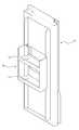
또한 두 도어(20) 중 냉장실 도어(20R)에는 도 17에 도시한 바와 같이 냉장실 도어(20R)를 개방하지 않고도 냉장실(111R) 내부의 저장물을 인출할 수 있도록 하기 위해 개구(20c)가 마련되어 있으며, 개구(20c)에는 개구(20c)를 개폐하기 위한 보조도어(20)가 설치되어 있다. 보조도어(20)는 그 하단이 본체(10)의 개구(20c) 인접부에 회전 가능하게 설치되어 회전하며 개구(20c)를 개폐하도록 되어 있다. 본 실시예에서 보조 도어(50)는 냉장실 도어(20R)에 마련되어 있으나 이에 한정되는 것은 아니며 필요에 따라 냉동실 도어(20F)에 보조 도어(50)가 형성되도록 하는 것도 가능하다.In addition, as shown in FIG. 17, an
또한 보조 도어(50)에 의해 개구(20c)가 폐쇄되어 있는 상태를 유지할 수 있도록 하기 위해 보조 도어(50)에는 락킹부재(51)가 마련되며, 도어(20)에는 락킹부재(51)를 선택적으로 락킹하는 락킹장치(60)가 마련되어, 락킹장치(60)가 보조 도어(50)에 마련된 락킹부재(51)를 락킹 또는 락킹 해제하도록 함으로써 보조 도어(50)를 락킹 또는 락킹 해제하여 보조 도어(50)에 의해 개구가 폐쇄되어 있는 상태를 그대로 유지할 수 있도록 하거나 보조 도어(50)가 개구(20c)로부터 이탈할 수 있는 상태가 되도록 한다.The
보조 도어(50)는 그 하단이 본체(10)에 힌지 결합되어 상하 방향으로 회전하며 개구(20c)를 개폐할 수 있도록 되어 있으며, 도어(20)에는 개구(20c) 내측으로 돌출되어 보조 도어(50)의 후면을 지지하는 보조 도어 지지부(20d)가 마련된다. 이때 개구(20c)는 보조 도어 지지부(20d)의 전방측에 형성되어 내측에 보조 도어(50)가 수용되는 제 1 개구부(20c-1)와, 보조 도어 지지부(20d)에 의해 형성되는 제 2 개구부(20c-2)를 포함하며, 보조 도어(50)의 후면은 제 2 개구부(20c-2)에 비하여 상대적으로 넓은 면적을 갖도록 형성되어 보조 도어(50) 후면의 테두리부가 보조 도어 지지부(20d)에 지지되도록 되어 있다.The lower end of the
또한 본 실시예에서 보조 도어(50)의 후면에는 금속재질로 이루어진 냉각판(52)이 배치된다. 냉각판은 보조 도어(50)가 폐쇄되어 있는 상태에서 냉장실(111R)의 냉기를 전달받아 냉각되었다가, 개구(20c)가 개방되고 보조 도어 후면(50)에 마련된 냉각판(52)에 저장물이 얹혀질 경우, 냉각판(52) 위에 얹혀진 저장물의 온도 상승을 지연시키는 역할을 수행한다.In the present embodiment, a cooling
락킹부재(51)는 보조 도어(50)의 후면 상측으로부터 상측으로 돌출되도록 형성되며, 락킹장치(60)는 락킹부재(51)와 대응하도록 도어(20)의 제 1 개구부(20c-1)의 상측 부위에 설치된다.The locking
도 25에 도시한 바와 같이 종래의 락킹장치(60')는 보조 도어 지지부(20d')에 설치되나, 보조 도어 지지부(20d')에 락킹장치(60')를 설치할 경우, 보조 도어 지지부(20d')에 락킹장치(60')를 설치하기 위한 공간을 확보하여야 하므로 보조 도어 지지부(20d')의 폭이 락킹장치(60')의 높이에 비해 상대적으로 넓게 형성되어야만 하여 불가피하게 넓어질 수 밖에 없으며, 보조 도어 지지부(20d')의 폭을 넓게 형성하면 그에 따라 개구(20c')의 면적은 작아질 수 밖에 없다. 또한 종래의 락킹장치는 상하 방향으로 회전하며 락킹부재에 걸리는 회전 후크(미도시)를 포함하는데, 회전 후크가 상하 방향으로 회전하기 위해서 락킹장치는 상하 방향으로 일정 이상의 두께를 갖도록 두껍게 형성되어야 하며, 이는 보조 도어 지지부의 폭을 증가시키는 요인으로 작용한다.25, the conventional locking device 60 'is provided on the auxiliary
따라서, 본 실시예에서 락킹장치(60)는 도 18에 도시한 바와 같이 도어(20)의 제 1 개구부(20c-1) 상측에 적어도 일부가 매립 설치되도록 되어 있으며, 보조 도어 지지부(20d)는 도어(20)의 락킹장치(60)의 후방측 부위로부터 개구(20c) 내측으로 돌출되어 있다.18, at least a part of the
락킹장치(60)의 일부가 개구(20c) 상측에 매립 설치될 수 있도록 하기 위해 도어의 제 1 개구부(20c-1)의 상측에는 락킹장치 설치홈(20e)이 상측으로 오목하게 마련된다. 락킹장치 설치홈(20e)은 락킹장치(60)의 상하 방향 두께에 비해 상대적으로 얕은 깊이를 갖도록 형성되어 락킹장치(60)의 일부 부위는 락킹장치 설치홈(20e) 내에 설치되고 나머지 부위는 제 1 개구부(20c-1) 내측으로 돌출되게 설치된다. 락킹 케이스(61)의 양측에는 스크류 등의 체결부재가 관통하여 설치되는 고정부(61c)가 마련되어, 고정부(61c)를 통해 락킹 케이스(61)가 락킹장치 설치홈(20e)에 고정 설치된다.A locking
이와 같이 락킹장치(60)의 적어도 일부가 도어(20)의 제 1 개구부(20c-1)의 상측으로 매립 설치되도록 하면, 매립된 락킹장치(60)의 깊이 만큼 보조 도어 지지부(20d)의 폭을 줄일 수 있게 되며, 이를 통해 제 2 개구부(20c-2)의 크기를 증가시킬 수 있다.When at least a part of the
또한 락킹부재(51)는 봉 형상으로 형성되어 보조 도어(50)의 내면 상부로부터 상방을 향하여 돌출되도록 설치된다. 이때, 락킹부재(51)의 선단은 보조 도어(50)의 상단과 대응하는 높이까지 돌출 형성시킬 수 있다.The locking
락킹장치(60)는 도 19에 도시한 바와 같이 락킹 케이스(61)와, 락킹 케이스(61)에 전후 방향으로 이동 가능하게 설치되는 슬라이딩부재(62)와, 슬라이딩부재(62)의 위치에 따라 좌우 방향으로 회전하며 선택적으로 락킹부재(51)에 걸리는 회전 후크(63)를 포함한다.19, the locking
상술한 바와 같이 락킹부재(51)를 봉 형상으로 형성하여 그 선단을 보조 도어(50)의 상단과 대응하는 높이로 돌출형성하고, 락킹장치(60)의 회전 후크(53)가 좌우 방향으로 회전하며 락킹부재(51)에 걸리도록 하면, 락킹장치(60)를 도어(20)의 제 1 개구부 상측에 매립 설치하더라고 락킹장치(60)에 의한 락킹부재(51)의 락킹은 안정적으로 이루어질 수 있다.The locking
락킹 케이스(61)에는 슬라이딩부재(62)가 이동 가능하게 설치되는 가이드부(61a)가 전후 방향으로 마련되며, 가이드부(61a)의 양측에는 슬라이딩부재(62)가 이동 가능하게 설치되는 제 1 레일부(61b)가 볼록 형성되며, 슬라이딩부재(62)의 양측에는 제 1 레일부(61b)와 대응하도록 오목 형성되는 제 2 레일부(62a)가 마련된다. 가이드부(61a) 내측에는 코일스프링으로 이루어져 슬라이딩부재(62)를 락킹 케이스(61)로부터 돌출되도록 탄성지지하는 한 쌍의 제 1 탄성부재(64)가 배치된다.The locking
회전 후크(63)는 힌지축(65)을 통해 슬라이딩부재(62)에 회전 가능하게 설치되며, 힌지축(65)에는 토션스프링으로 이루어져 회전 후크(63)가 일 방향으로 회전하도록 탄성지지하는 제 2 탄성부재(66)가 설치된다.The
또한 락킹장치(60)는 슬라이딩부재(62)가 가이드부(61a) 내측에 수용되어 있는 상태나 슬라이딩부재(62)의 일정 부위가 가이드부(61a)로부터 돌출된 상태를 유지할 수 있도록 하기 위한 가이드부재(68)를 포함한다.The locking
가이드부재(68)는 슬라이딩부재(62)와 상호작용하며 슬라이딩부재(62)의 이동을 제한하는데, 이를 위해 슬라이딩부재(62)의 상면에는 캠홀(62b)이 마련되어 있으며, 가이드부재(68)는 대략 역 U자 형상으로 형성되어 그 일단이 캠홀(62a)에 이동 가능하게 설치되고 타단이 락킹 케이스(61)에 회전 가능하게 설치된다. 락킹 케이스(61)에는 가이드부재(68)의 상측으로의 이동을 제한하기 위한 지지플레이트(69)가 설치된다.The
따라서, 도 20에 도시한 바와 같이 슬라이딩부재(62)가 락킹 케이스(61)의 가이드부(61a) 내에 수용되어 있는 상태에서 회전 후크(63)는 가이드부(61a)의 측면에 의해 지지되어 락킹부재(51)를 락킹한다. 또한 도 21에 도시한 바와 같이 슬라이딩부재(62)가 락킹 케이스(61)의 가이드부(61a)로부터 일정 이상 돌출되면 회전 후크(63)는 가이드부(61a)로부터 이탈하며, 가이드부(61a)로부터 이탈한 회전 후크(63)는 제 2 탄성부재(66)의 탄성복원력에 의해 일 방향으로 회전하게 되므로 락킹부재(51)가 락킹은 해제된다.20, the rotating
또한 도어(20)의 배면에는 도 22에 도시한 바와 같이 개구(20c)를 통해 인출될 저장물이 담기는 도어 선반(90)이 배치된다. 본 실시예에서는 상술한 바와 같이 보조 도어 지지부(20d)의 폭을 줄여 제 2 개구부(20c-2)의 크기를 증가시킬 수 있도록 되어 있으므로, 도어 선반(90)은 개구(20c)를 보다 효율적으로 활용할 수 있도록 하기 위해 도어 선반(90)에는 그 하부에 마련된 제 1 저장부(91)와, 제 1 저장부(91) 상측에 마련된 제 2 저장부(92)가 일체로 마련되어 2단 구조로 이루어진다. 본 실시예에서 제 1 저장부(91)는 제 2 저장부(92)에 비하여 높은 높이로 형성되어 페트병과 같이 높이가 높은 저장물을 저장할 수 있도록 되어 있으며, 제 2 저장부(92)는 제 1 저장부(91)에 비해 낮은 높이를 갖도록 형성되어 캔음료 등과 같이 높이가 낮은 저장물을 저장할 수 있도록 되어 있다.On the rear surface of the
본 발명은 상기에서 기재된 실시예에 한정되는 것은 아니며, 본 발명의 사상 에서 벗어나지 않는 범위에서 다양하게 수정 및 변형할 수 있다는 점은 이 기술의 분야에서 통상의 지식을 가진 자에게 자명하다. 따라서 수정예 또는 변형예들은 본 발명의 특허청구범위에 속한다 하여야 할 것이다.It will be apparent to those skilled in the art that various modifications and variations can be made in the present invention without departing from the spirit and scope of the invention. Accordingly, modifications or variations are intended to fall within the scope of the appended claims.
10: 본체 111F: 냉동실
111R: 냉장실 20F: 냉동실 도어
20R: 냉장실 도어 30: 상부 힌지모듈
40: 하부 힌지모듈 50: 보조 도어
51: 락킹부재 60: 락킹장치
70: 유동방지부재 80: 장식유닛
90: 도어 선반10:
111R:
20R: refrigerator door 30: upper hinge module
40: lower hinge module 50: auxiliary door
51: locking member 60: locking device
70: flow preventing member 80: decorative unit
90: Door Shelf
Claims (17)
Translated fromKorean상기 냉동실과 상기 냉장실을 각각 개폐하는 냉동실 도어 및 냉장실 도어와,
상기 냉동실 도어 및 상기 냉장실 도어의 전면을 각각 형성하는 한 쌍의 도어 전면패널과,
상기 냉동실 도어 및 상기 냉장실 도어에 서로 대향되게 마련되어 한 쌍의 상기 도어 전면패널의 측단을 각각 지지하며, 상기 도어 전면 패널과 동일면을 형성하는 한 쌍의 도어 트림과,
상기 한 쌍의 도어 트림으로부터 각각 측방으로 연장되는 한 쌍의 손잡이와,
상기 냉동실 도어와 상기 냉장실 도어의 서로 대향된 일 측면을 각각 형성하는 한 쌍의 제 1 도어 측면프레임과,
한 쌍의 상기 제 1 도어 측면프레임에 전방 및 측방을 향하여 개방되도록 단차지게 각각 마련된 한 쌍의 손잡이홈과,
상기 한 쌍의 손잡이는 상기 손잡이홈의 전방측을 전체적으로 덮도록 연장되는 제 1 손잡이부와, 상기 손잡이홈의 전방측 일부를 제한적으로 덮도록 연장되는 제 2 손잡이부를 각각 포함하며,
상기 한 쌍의 냉동실 도어 및 상기 냉장실 도어 중 어느 하나에는 상부에 상기 제 1 손잡이부가 마련되고 하부에 제 2 손잡이부가 마련되며, 다른 하나에는 상부에 제 2 손잡이부가 마련되고 하부에 제 1 손잡이부가 마련되는 냉장고.A main body provided with a freezing compartment and a refrigerating compartment separated from each other by a partition wall,
A freezing compartment door and a refrigerating compartment door for opening and closing the freezing compartment and the refrigerating compartment, respectively,
A pair of door front panels each forming a front surface of the freezer compartment door and the refrigerator compartment door,
A pair of door trim portions provided on the freezer compartment door and the refrigerating compartment door so as to face each other to respectively support the side ends of the pair of door front panels and form the same surface as the door front panel,
A pair of handles extending laterally from the pair of door trim,
A pair of first door side frames each forming a side surface opposite to the freezing chamber door and the refrigerating chamber door,
A pair of knob grooves provided on the pair of first door side frames so as to be stepped to be opened forward and laterally,
Wherein the pair of handles includes a first handle portion extending so as to cover the front side of the handle groove and a second handle portion extending to limitly cover a part of the front side of the handle groove,
One of the pair of freezer compartment doors and the refrigerator compartment door is provided with the first handle portion at the upper portion and the second handle portion at the lower portion and the second handle portion is provided at the upper portion and the first handle portion is provided at the lower portion. Become a refrigerator.
한 쌍의 상기 도어 트림은 오목 형성되어 상기 도어 전면패널의 일측단을 지지하는 패널 지지부를 각각 포함하는 냉장고.11. The method of claim 10,
And a pair of the door trim are recessed to support one side edge of the door front panel.
상기 냉동실 도어 및 상기 냉장실 도어에 각각 마련된 한 쌍의 상기 손잡이는 서로 이격배치되는 냉장고.11. The method of claim 10,
And the pair of handles provided on the freezer compartment door and the refrigerator compartment door are spaced apart from each other.
장식을 위해 상기 도어 전면패널의 후면에 배치되는 장식유닛을 더 포함하며,
상기 장식유닛은 광을 반사 또는 방사하는 복수의 장식부재와, 상기 복수의 장식부재가 일정 형태를 이룬 상태로 고정 설치되도록 하는 고정플레이트를 포함하는 냉장고.11. The method of claim 10,
And a decorative unit disposed on a rear surface of the door front panel for decoration,
The decorative unit includes a plurality of decorative members for reflecting or radiating light, and a fixing plate for fixing the decorative members in a fixed form.
Priority Applications (4)
| Application Number | Priority Date | Filing Date | Title |
|---|---|---|---|
| KR1020100077596AKR101752670B1 (en) | 2010-08-11 | 2010-08-11 | Refrigerator |
| US13/137,393US8567885B2 (en) | 2010-08-11 | 2011-08-10 | Refrigerator |
| CN201110234930.XACN102374733B (en) | 2010-08-11 | 2011-08-11 | Refrigerator |
| EP11177180.4AEP2418442A3 (en) | 2010-08-11 | 2011-08-11 | Refrigerator |
Applications Claiming Priority (1)
| Application Number | Priority Date | Filing Date | Title |
|---|---|---|---|
| KR1020100077596AKR101752670B1 (en) | 2010-08-11 | 2010-08-11 | Refrigerator |
Publications (2)
| Publication Number | Publication Date |
|---|---|
| KR20120015249A KR20120015249A (en) | 2012-02-21 |
| KR101752670B1true KR101752670B1 (en) | 2017-07-03 |
Family
ID=44763797
Family Applications (1)
| Application Number | Title | Priority Date | Filing Date |
|---|---|---|---|
| KR1020100077596AExpired - Fee RelatedKR101752670B1 (en) | 2010-08-11 | 2010-08-11 | Refrigerator |
Country Status (4)
| Country | Link |
|---|---|
| US (1) | US8567885B2 (en) |
| EP (1) | EP2418442A3 (en) |
| KR (1) | KR101752670B1 (en) |
| CN (1) | CN102374733B (en) |
Families Citing this family (39)
| Publication number | Priority date | Publication date | Assignee | Title |
|---|---|---|---|---|
| JP6121802B2 (en)* | 2012-10-12 | 2017-04-26 | 東芝ライフスタイル株式会社 | refrigerator |
| KR101860718B1 (en)* | 2013-02-21 | 2018-05-24 | 삼성전자주식회사 | Refrigerator having double doors |
| US8960934B2 (en)* | 2013-04-08 | 2015-02-24 | Samsung Electronics Co., Ltd. | Refrigerator and method of manufacturing the same |
| JP6073199B2 (en)* | 2013-08-02 | 2017-02-01 | 日立アプライアンス株式会社 | refrigerator |
| EP2868853B1 (en)* | 2013-10-31 | 2018-12-26 | Electrolux Appliances Aktiebolag | Household appliance comprising an actuation system |
| CN106104182B (en)* | 2014-01-07 | 2020-09-15 | 三星电子株式会社 | Refrigerator with a door |
| KR101662398B1 (en) | 2014-07-16 | 2016-10-04 | 엘지전자 주식회사 | Door for Refrigerator and Manufacturing Method for the same |
| EP2975345B1 (en) | 2014-07-16 | 2019-01-02 | LG Electronics Inc. | Refrigerator door and manufacturing method of the same |
| CN105258438B (en)* | 2014-07-18 | 2019-06-25 | 博西华电器(江苏)有限公司 | Refrigerator with handle slot |
| CN105333680B (en)* | 2014-07-18 | 2019-02-26 | 博西华电器(江苏)有限公司 | Refrigerator |
| KR101646378B1 (en)* | 2014-11-11 | 2016-08-05 | 동부대우전자 주식회사 | A refrigerator door frame and a method for manufacturing the same |
| KR101668707B1 (en)* | 2015-03-06 | 2016-10-24 | 엘지전자 주식회사 | Door for Refrigerator |
| WO2016200050A1 (en) | 2015-06-11 | 2016-12-15 | Lg Electronics Inc. | Refrigerator and control method for refrigerator |
| CN104880018B (en)* | 2015-06-17 | 2018-03-16 | 合肥美的电冰箱有限公司 | Display control board anti-dewfall structure and refrigerator |
| CN105089400A (en)* | 2015-08-05 | 2015-11-25 | 青岛海尔股份有限公司 | Hinge and refrigerator having hinge |
| DE102015221885A1 (en)* | 2015-11-06 | 2017-05-24 | BSH Hausgeräte GmbH | Door with a door frame and a handle recess element and household refrigeration appliance with such a door |
| KR102404358B1 (en)* | 2016-01-12 | 2022-06-02 | 엘지전자 주식회사 | transparent display device |
| CN106123457B (en)* | 2016-06-23 | 2018-09-04 | 青岛海尔股份有限公司 | Refrigerator |
| EP3287722B1 (en) | 2016-08-23 | 2020-07-15 | Dometic Sweden AB | Cabinet for a recreational vehicle |
| DE102016216126A1 (en) | 2016-08-26 | 2018-03-01 | Dometic Sweden Ab | Cooling device for a recreational vehicle |
| CN106766597B (en)* | 2016-12-30 | 2023-05-30 | 广东格兰仕集团有限公司 | Assembly structure of refrigerator door frame ornamental strip and handle |
| CN108534425A (en)* | 2017-03-03 | 2018-09-14 | 博西华电器(江苏)有限公司 | Refrigerator |
| KR102551391B1 (en)* | 2017-12-06 | 2023-07-05 | 엘지전자 주식회사 | Refrigerator and out plate for refrigerator |
| MX2020007622A (en)* | 2018-01-17 | 2020-09-14 | Anthony Inc | Door for mounting a removable electronic display. |
| DE102018204911A1 (en)* | 2018-03-07 | 2019-09-12 | BSH Hausgeräte GmbH | Domestic appliance with a sensor unit arranged on a closure element |
| US11193709B2 (en) | 2018-06-14 | 2021-12-07 | Cse, Inc. | Appliance door handles with integrated graphical displays |
| WO2020126024A1 (en)* | 2018-12-21 | 2020-06-25 | Electrolux Appliances Aktiebolag | Wine cooler with reversible door |
| US10514722B1 (en) | 2019-03-29 | 2019-12-24 | Anthony, Inc. | Door for mounting a removable electronic display |
| WO2020213861A1 (en) | 2019-04-15 | 2020-10-22 | Samsung Electronics Co., Ltd. | Refrigerator |
| KR102312667B1 (en) | 2019-04-15 | 2021-10-15 | 삼성전자주식회사 | Refrigerator |
| DE102019207919A1 (en) | 2019-05-29 | 2020-12-03 | Dometic Sweden Ab | Hinge mechanism, compartment door arrangement with such a hinge mechanism, cabinet or refrigerator with such a hinge mechanism and / or compartment door arrangement, and recreational vehicle |
| MX2021001927A (en)* | 2019-08-20 | 2021-04-28 | Samsung Electronics Co Ltd | Refrigerator and home appliance. |
| KR20210098622A (en)* | 2020-02-03 | 2021-08-11 | 삼성전자주식회사 | Refrigerator |
| KR20210125379A (en) | 2020-04-08 | 2021-10-18 | 삼성전자주식회사 | Refrigerator |
| CN113865235B (en)* | 2020-06-30 | 2023-02-17 | 青岛海尔电冰箱有限公司 | Refrigerator door with replaceable door face |
| CN114076479A (en)* | 2020-08-10 | 2022-02-22 | 青岛海尔特种电冰箱有限公司 | Refrigerator door with replaceable door face |
| CN114183956A (en)* | 2020-09-15 | 2022-03-15 | 博西华家用电器有限公司 | Refrigerator with a door |
| CN113294963B (en)* | 2021-05-20 | 2022-12-20 | 青岛海尔电冰箱有限公司 | Handle assembly of cold storage and freezing device door body and cold storage and freezing device door body |
| KR20240102523A (en)* | 2022-12-26 | 2024-07-03 | 엘지전자 주식회사 | Refrigerator and home appliance |
Citations (2)
| Publication number | Priority date | Publication date | Assignee | Title |
|---|---|---|---|---|
| JP2001153538A (en)* | 1999-11-24 | 2001-06-08 | Toshiba Corp | Refrigerator door |
| KR100904322B1 (en)* | 2008-01-23 | 2009-06-23 | 엘지전자 주식회사 | Refrigerator and Fridge Door |
Family Cites Families (35)
| Publication number | Priority date | Publication date | Assignee | Title |
|---|---|---|---|---|
| US2653851A (en)* | 1947-05-03 | 1953-09-29 | Avco Mfg Corp | Cabinet having improved means for facilitating opening doors singly or in multiple |
| US5048233A (en)* | 1987-05-01 | 1991-09-17 | Northland Corporation | Refrigerator door and method of manufacturing same |
| JPH05126461A (en)* | 1991-11-07 | 1993-05-21 | Matsushita Refrig Co Ltd | Thermal insulation door |
| US5358326A (en)* | 1993-01-14 | 1994-10-25 | General Electric Company | Refrigerator with improved door front and handle attachment |
| JPH06221747A (en)* | 1993-01-21 | 1994-08-12 | Matsushita Refrig Co Ltd | Door for refrigerator |
| DE10045236B4 (en)* | 2000-09-13 | 2013-08-22 | BSH Bosch und Siemens Hausgeräte GmbH | Dishwasher for installation behind a furniture front panel |
| JP4222733B2 (en)* | 2001-01-15 | 2009-02-12 | 三洋電機株式会社 | Cooling storage |
| BR0205140B1 (en) | 2002-11-25 | 2011-04-05 | cabinet front door handle arrangement. | |
| KR100488074B1 (en)* | 2003-03-22 | 2005-05-06 | 엘지전자 주식회사 | Door structure of refrigerator |
| JP3839801B2 (en)* | 2003-07-09 | 2006-11-01 | 吉岡電気工業株式会社 | Cover panel unit for refrigerator |
| JP4179244B2 (en)* | 2004-08-06 | 2008-11-12 | 三菱電機株式会社 | refrigerator |
| US8516659B2 (en)* | 2005-01-12 | 2013-08-27 | Whirlpool Corporation | Refrigerator handle mounting arrangement having pin and cavity interlock |
| EP4206590B1 (en)* | 2005-07-20 | 2024-09-04 | LG Electronics Inc. | Refrigerator door and method of manufacture thereof |
| CN200989708Y (en)* | 2006-11-17 | 2007-12-12 | 海尔集团公司 | Electric refrigerator door and electric refrigerator using the same door |
| US8104853B2 (en)* | 2006-12-19 | 2012-01-31 | Samsung Electronics Co., Ltd. | Refrigerator and method of manufacturing door thereof |
| US7618295B2 (en)* | 2007-01-04 | 2009-11-17 | Whirlpool Corporation | Adapter and consumer electronic device functional unit |
| KR100877989B1 (en)* | 2007-11-15 | 2009-01-12 | 엘지전자 주식회사 | Refrigerator Door |
| KR101484039B1 (en)* | 2008-01-11 | 2015-01-20 | 삼성전자 주식회사 | Door opening device of refrigerator |
| JP5178208B2 (en) | 2008-01-15 | 2013-04-10 | 三菱電機株式会社 | refrigerator |
| KR101576672B1 (en)* | 2008-02-21 | 2015-12-10 | 엘지전자 주식회사 | Refrigerator and refrigerator door |
| KR101346502B1 (en)* | 2008-02-21 | 2013-12-31 | 엘지전자 주식회사 | Refrigerator and method for manufacturing a door of refrigerator |
| KR101455861B1 (en)* | 2008-02-21 | 2014-11-03 | 엘지전자 주식회사 | Refrigerator and refrigerator door handle |
| CN101603763B (en)* | 2008-06-12 | 2012-10-17 | 海尔集团公司 | Refrigeration equipment and its door |
| EP2159521A1 (en)* | 2008-08-27 | 2010-03-03 | Panasonic Corporation | Refrigerator |
| DE202008011437U1 (en)* | 2008-08-27 | 2009-02-19 | Panasonic Corp., Kadoma | fridge |
| PL2331892T3 (en)* | 2008-09-09 | 2012-04-30 | Arcelik As | A household appliance |
| KR20110022849A (en)* | 2009-08-28 | 2011-03-08 | 삼성전자주식회사 | Refrigerator |
| KR20110037303A (en)* | 2009-10-06 | 2011-04-13 | 삼성전자주식회사 | Refrigerator |
| KR20110042786A (en)* | 2009-10-20 | 2011-04-27 | 삼성전자주식회사 | Method of manufacturing refrigerators and freezers |
| KR101720535B1 (en)* | 2010-05-07 | 2017-03-28 | 삼성전자주식회사 | Refrigerator and door thereof |
| KR101650307B1 (en)* | 2010-05-07 | 2016-09-05 | 삼성전자주식회사 | Door handle and refrigerator having the same |
| KR101785343B1 (en)* | 2010-08-11 | 2017-10-17 | 삼성전자주식회사 | Refrigerator |
| KR20120015248A (en)* | 2010-08-11 | 2012-02-21 | 삼성전자주식회사 | Refrigerator |
| KR20120015247A (en)* | 2010-08-11 | 2012-02-21 | 삼성전자주식회사 | Refrigerator |
| KR101740368B1 (en)* | 2010-08-26 | 2017-05-29 | 삼성전자주식회사 | Refrigerator |
- 2010
- 2010-08-11KRKR1020100077596Apatent/KR101752670B1/ennot_activeExpired - Fee Related
- 2011
- 2011-08-10USUS13/137,393patent/US8567885B2/enactiveActive
- 2011-08-11CNCN201110234930.XApatent/CN102374733B/ennot_activeExpired - Fee Related
- 2011-08-11EPEP11177180.4Apatent/EP2418442A3/ennot_activeWithdrawn
Patent Citations (2)
| Publication number | Priority date | Publication date | Assignee | Title |
|---|---|---|---|---|
| JP2001153538A (en)* | 1999-11-24 | 2001-06-08 | Toshiba Corp | Refrigerator door |
| KR100904322B1 (en)* | 2008-01-23 | 2009-06-23 | 엘지전자 주식회사 | Refrigerator and Fridge Door |
Also Published As
| Publication number | Publication date |
|---|---|
| CN102374733A (en) | 2012-03-14 |
| US20120037644A1 (en) | 2012-02-16 |
| CN102374733B (en) | 2015-11-25 |
| EP2418442A2 (en) | 2012-02-15 |
| EP2418442A3 (en) | 2014-01-29 |
| KR20120015249A (en) | 2012-02-21 |
| US8567885B2 (en) | 2013-10-29 |
Similar Documents
| Publication | Publication Date | Title |
|---|---|---|
| KR101752670B1 (en) | Refrigerator | |
| KR101785343B1 (en) | Refrigerator | |
| KR101506145B1 (en) | Refrigerator | |
| CN102374732B (en) | Refrigerator | |
| EP2450651B1 (en) | Refrigerator | |
| EP1903288B1 (en) | Drawer Type Door and Refrigerator having the Same | |
| EP2594874B1 (en) | Refrigerator | |
| KR20210125379A (en) | Refrigerator | |
| US11112167B2 (en) | Refrigerator | |
| EP2072937A2 (en) | Drawer for a refrigerating apparatus, and related refrigerating apparatus | |
| US12372294B2 (en) | Refrigerator | |
| US12055340B2 (en) | Endcap assembly for a door of a refrigeration appliance | |
| CN101963421B (en) | Refrigerator | |
| JP3886371B2 (en) | Storage door structure | |
| KR20090049220A (en) | Refrigerator with cabinet |
Legal Events
| Date | Code | Title | Description |
|---|---|---|---|
| PA0109 | Patent application | St.27 status event code:A-0-1-A10-A12-nap-PA0109 | |
| R17-X000 | Change to representative recorded | St.27 status event code:A-3-3-R10-R17-oth-X000 | |
| AMND | Amendment | ||
| E13-X000 | Pre-grant limitation requested | St.27 status event code:A-2-3-E10-E13-lim-X000 | |
| P11-X000 | Amendment of application requested | St.27 status event code:A-2-2-P10-P11-nap-X000 | |
| P13-X000 | Application amended | St.27 status event code:A-2-2-P10-P13-nap-X000 | |
| PG1501 | Laying open of application | St.27 status event code:A-1-1-Q10-Q12-nap-PG1501 | |
| R18-X000 | Changes to party contact information recorded | St.27 status event code:A-3-3-R10-R18-oth-X000 | |
| A201 | Request for examination | ||
| PA0201 | Request for examination | St.27 status event code:A-1-2-D10-D11-exm-PA0201 | |
| P22-X000 | Classification modified | St.27 status event code:A-2-2-P10-P22-nap-X000 | |
| D13-X000 | Search requested | St.27 status event code:A-1-2-D10-D13-srh-X000 | |
| D14-X000 | Search report completed | St.27 status event code:A-1-2-D10-D14-srh-X000 | |
| E902 | Notification of reason for refusal | ||
| PE0902 | Notice of grounds for rejection | St.27 status event code:A-1-2-D10-D21-exm-PE0902 | |
| AMND | Amendment | ||
| P11-X000 | Amendment of application requested | St.27 status event code:A-2-2-P10-P11-nap-X000 | |
| P13-X000 | Application amended | St.27 status event code:A-2-2-P10-P13-nap-X000 | |
| E601 | Decision to refuse application | ||
| PE0601 | Decision on rejection of patent | St.27 status event code:N-2-6-B10-B15-exm-PE0601 | |
| AMND | Amendment | ||
| E13-X000 | Pre-grant limitation requested | St.27 status event code:A-2-3-E10-E13-lim-X000 | |
| P11-X000 | Amendment of application requested | St.27 status event code:A-2-2-P10-P11-nap-X000 | |
| P13-X000 | Application amended | St.27 status event code:A-2-2-P10-P13-nap-X000 | |
| PX0901 | Re-examination | St.27 status event code:A-2-3-E10-E12-rex-PX0901 | |
| PX0701 | Decision of registration after re-examination | St.27 status event code:A-3-4-F10-F13-rex-PX0701 | |
| X701 | Decision to grant (after re-examination) | ||
| GRNT | Written decision to grant | ||
| PR0701 | Registration of establishment | St.27 status event code:A-2-4-F10-F11-exm-PR0701 | |
| PR1002 | Payment of registration fee | St.27 status event code:A-2-2-U10-U11-oth-PR1002 Fee payment year number:1 | |
| PG1601 | Publication of registration | St.27 status event code:A-4-4-Q10-Q13-nap-PG1601 | |
| PR1001 | Payment of annual fee | St.27 status event code:A-4-4-U10-U11-oth-PR1001 Fee payment year number:4 | |
| PR1001 | Payment of annual fee | St.27 status event code:A-4-4-U10-U11-oth-PR1001 Fee payment year number:5 | |
| PR1001 | Payment of annual fee | St.27 status event code:A-4-4-U10-U11-oth-PR1001 Fee payment year number:6 | |
| PC1903 | Unpaid annual fee | St.27 status event code:A-4-4-U10-U13-oth-PC1903 Not in force date:20230627 Payment event data comment text:Termination Category : DEFAULT_OF_REGISTRATION_FEE | |
| PC1903 | Unpaid annual fee | St.27 status event code:N-4-6-H10-H13-oth-PC1903 Ip right cessation event data comment text:Termination Category : DEFAULT_OF_REGISTRATION_FEE Not in force date:20230627 |