KR101751395B1 - Apparatus and method for ringer drop detection, recording medium for performing the method - Google Patents
Apparatus and method for ringer drop detection, recording medium for performing the methodDownload PDFInfo
- Publication number
- KR101751395B1 KR101751395B1KR1020150168249AKR20150168249AKR101751395B1KR 101751395 B1KR101751395 B1KR 101751395B1KR 1020150168249 AKR1020150168249 AKR 1020150168249AKR 20150168249 AKR20150168249 AKR 20150168249AKR 101751395 B1KR101751395 B1KR 101751395B1
- Authority
- KR
- South Korea
- Prior art keywords
- light receiving
- droplet
- drip chamber
- liquid
- optical signals
- Prior art date
- Legal status (The legal status is an assumption and is not a legal conclusion. Google has not performed a legal analysis and makes no representation as to the accuracy of the status listed.)
- Active
Links
Images


Classifications
- A—HUMAN NECESSITIES
- A61—MEDICAL OR VETERINARY SCIENCE; HYGIENE
- A61M—DEVICES FOR INTRODUCING MEDIA INTO, OR ONTO, THE BODY; DEVICES FOR TRANSDUCING BODY MEDIA OR FOR TAKING MEDIA FROM THE BODY; DEVICES FOR PRODUCING OR ENDING SLEEP OR STUPOR
- A61M5/00—Devices for bringing media into the body in a subcutaneous, intra-vascular or intramuscular way; Accessories therefor, e.g. filling or cleaning devices, arm-rests
- A61M5/14—Infusion devices, e.g. infusing by gravity; Blood infusion; Accessories therefor
- A61M5/168—Means for controlling media flow to the body or for metering media to the body, e.g. drip meters, counters ; Monitoring media flow to the body
- A61M5/16831—Monitoring, detecting, signalling or eliminating infusion flow anomalies
- A—HUMAN NECESSITIES
- A61—MEDICAL OR VETERINARY SCIENCE; HYGIENE
- A61M—DEVICES FOR INTRODUCING MEDIA INTO, OR ONTO, THE BODY; DEVICES FOR TRANSDUCING BODY MEDIA OR FOR TAKING MEDIA FROM THE BODY; DEVICES FOR PRODUCING OR ENDING SLEEP OR STUPOR
- A61M5/00—Devices for bringing media into the body in a subcutaneous, intra-vascular or intramuscular way; Accessories therefor, e.g. filling or cleaning devices, arm-rests
- A61M5/14—Infusion devices, e.g. infusing by gravity; Blood infusion; Accessories therefor
- A61M5/168—Means for controlling media flow to the body or for metering media to the body, e.g. drip meters, counters ; Monitoring media flow to the body
- A61M5/16877—Adjusting flow; Devices for setting a flow rate
Landscapes
- Health & Medical Sciences (AREA)
- Vascular Medicine (AREA)
- Engineering & Computer Science (AREA)
- Anesthesiology (AREA)
- Biomedical Technology (AREA)
- Heart & Thoracic Surgery (AREA)
- Hematology (AREA)
- Life Sciences & Earth Sciences (AREA)
- Animal Behavior & Ethology (AREA)
- General Health & Medical Sciences (AREA)
- Public Health (AREA)
- Veterinary Medicine (AREA)
- Physics & Mathematics (AREA)
- Fluid Mechanics (AREA)
- Infusion, Injection, And Reservoir Apparatuses (AREA)
Abstract
Translated fromKoreanDescription
Translated fromKorean본 발명은 수액 방울 검출 장치 및 방법, 이를 수행하기 위한 기록매체에 관한 것으로서, 더욱 상세하게는 수액팩으로부터 점적 챔버로 낙하하는 수액 방울 검출 장치 및 방법, 이를 수행하기 위한 기록매체에 관한 것이다.The present invention relates to an apparatus and method for detecting a droplet of droplets, and a recording medium for performing the method. More particularly, the present invention relates to an apparatus and method for detecting droplets falling from a droplet pack into a drop chamber, and a recording medium for performing the method.
일반적으로 병원에서는 수액, 약물 또는 혈액 공급을 위해 정맥 속에 직접 주사 바늘을 삽입하여 수액 등을 주입하는 정맥 주사 요법이 사용된다.Generally, in hospitals, intravenous infusion is used to inject sap into the vein by inserting an injection needle directly into the vein to supply fluid, drugs or blood.
도 1은 이러한 정맥 주사 주입 장치를 도시한 도면이다. 도 1을 참조하면, 정맥 주사 주입 장치는 일반적으로 수액 등이 저장되는 수액팩(20), 수액팩(20)이 거치되는 거치대(60), 수액팩(20)의 하부에 연결되어 수액팩(20)으로부터 수액 등이 흘러나와 방울을 맺게 하며, 해당 방울을 눈으로 확인할 수 있도록 투명한 소재로 형성되는 점적 챔버(10), 점적 챔버(10)의 하부에 연결되는 호스(40), 수액 등의 주입량을 조절하기 위한 수액 주입 조절기(30) 및 주사 바늘(50)로 구성된다.Fig. 1 is a view showing such an intravenous injection device. Referring to FIG. 1, the intravenous injection device generally includes a liquid-receiving
여기에서, 수액 주입 조절기(30)를 수동으로 돌리는 방식으로 조절하여 점적 챔버(10) 내부의 압력을 조절할 수 있으며, 구체적으로는, 수액 주입 조절기(30)를 열면 점적 챔버(10) 내부의 압력이 중력에 의하여 낮아지므로, 수액팩(20)으로부터 점적 챔버(10)로 수액 방울이 낙하할 수 있다. 반면, 수액 주입 조절기(30)를 닫으면, 점적 챔버(10) 내부의 압력이 높아지므로, 수액팩(20)으로부터 점적 챔버(10)로 수액이 흘러나오지 않는다.In this case, the
한편, 정맥 주사 요법에 있어서 정확한 속도로 정확한 용량의 수액이 주입되는 것이 중요하므로, 수액팩(20)으로부터 점적 챔버(10)로 낙하하는 수액 방울을 계수하여 누적 주입량을 산출하고 그 결과에 따라 수액 주입 조절기(30)를 조절하는 것이 바람직하다.Since it is important for the intravenous infusion treatment to inject the infusion fluid of the correct capacity at the correct rate, the infusion drops dropping from the
이를 위해, 수액팩(20)으로부터 점적 챔버(10)로 낙하하는 수액 방울을 검출하기 위한 다양한 방법이 제안되었다. 대표적으로는, 도 2와 같이, 광 송출부와 광 수신부를 포함하는 광학 센서를 이용하여 점적 챔버(10)의 수액 방울을 검출하는 방법이 있다. 도 2는 광학식 수액 방울 검출 장치의 일 예를 도시한 도면이다.To this end, various methods have been proposed for detecting droplets falling from the
먼저, 도 2의 (a)를 참조하면, 점적 챔버(10)의 외측 양측면에 각각 하나의 광 송출부와 광 수신부를 배치한 수액 방울 검출 장치는, 광 수신부는 광 송출부로부터 출력되어 점적 챔버(10)를 투과한 광 신호를 수신할 수 있으며, 광 수신부에서 수신한 광 신호에 기반하여 수액 방울을 검출할 수 있다.2 (a), in the liquid droplet detecting apparatus in which one light emitting unit and a light receiving unit are disposed on both outer sides of the
또는, 도 2의 (b)를 참조하면, 점적 챔버(10)의 외측 일면에 광 송출부와 광 수신부를 배치하고, 외측 타면에는 반사 수단, 일예로, 거울을 배치한 수액 방울 검출 장치는, 광 수신부는 광 송출부로부터 출력되어 점적 챔버(10)로 투과되며, 반사 수단에 의해 반사되는 광 신호를 수신할 수 있으며, 광 수신부에서 수신한 광 신호에 기반하여 수액 방울을 검출할 수 있다.2 (b), a droplet receiving unit and a light receiving unit are disposed on the outer surface of the
이처럼, 종래의 수액 방울 검출 장치는 점적 챔버(10)의 외측 양면 또는 일면에 하나의 광 송출부 및 광 수신부를 배치하는 단일 센서 구조를 가지므로, 수액팩(20)으로부터 점적 챔버(10)로 낙하하는 수액 방울의 유무만을 검출할 수 있다.Since the conventional liquid droplet detecting apparatus has a single sensor structure for disposing one light emitting portion and one light receiving portion on both sides or both sides of the
또한, 검출된 수액 방울을 계수하고 점적 챔버(10)의 기구적 특성에 따라 미리 저장된 수액 방울의 부피 정보를 곱하여 누적 주입 수액량을 산출할 수 있다.The accumulated infusion liquid amount can be calculated by counting the detected liquid droplets and multiplying the volume information of the previously stored liquid droplets by the mechanical characteristics of the
그러나, 수액 방울의 부피는 점적 챔버의 기구적 특성, 압력, 온도, 습도 등 주변 환경의 요인으로 인하여 일정하지 않으며, 이에 따라 누적 주입 수액량에 있어서 큰 오차가 발생할 수 있다.However, the volume of the droplet is not constant due to factors of the surrounding environment such as mechanical characteristics of the drip chamber, pressure, temperature, and humidity, and thus a large error may occur in the cumulative amount of infusion.
이와 같이, 종래의 수액 방울 검출 장치는 수액 방울의 낙하 여부만을 검출할 수 있을 뿐 수액 방울의 부피는 산출할 수 없으므로 결과적으로는 정확한 누적 주입 수액량을 산출하는 데 어려움이 있으며 이는 의료 사고로 이어질 수 있다.As described above, the conventional liquid droplet detecting apparatus can detect only the drop of the liquid droplet, and can not calculate the volume of the liquid droplet. As a result, it is difficult to calculate the accurate cumulative liquid infusion amount, have.
본 발명의 일측면은 수액 방울 검출 장치 및 방법, 이를 수행하기 위한 기록매체에 관한 것으로서, 복수의 광 센서를 포함하여 수액팩으로부터 점적 챔버로 낙하하는 수액 방울을 검출하고 해당 수액 방울의 부피를 산출하는 수액 방울 검출 장치 및 방법, 이를 수행하기 위한 기록매체를 제공한다.An aspect of the present invention relates to an apparatus and method for detecting droplets of droplets, a recording medium for performing the same, and a method for detecting droplets falling from a droplet pack into a droplet dispenser, And a recording medium for performing the method.
본 발명의 다른 측면은 복수의 광 센서로부터 수신하는 신호에 기반하여 점적 챔버의 자세 변화 여부를 판단하는 수액 방울 검출 장치 및 방법, 이를 수행하기 위한 기록매체를 제공한다.Another aspect of the present invention provides an apparatus and method for detecting a drop of a drop chamber based on a signal received from a plurality of optical sensors, and a recording medium for performing the method.
본 발명의 일 측면은 수액팩으로부터 점적 챔버로 낙하하는 수액 방울을 검출하는 수액 방울 검출 장치에 있어서, 상기 점적 챔버의 외측 일면을 향하여 배치되는 복수의 광 송출부를 포함하고, 상기 복수의 광 송출부를 통해 복수의 광 신호를 상기 점적 챔버로 투과시키는 발광 센서; 상기 점적 챔버의 외측 타면을 향하여 배치되는 복수의 광 수신부를 포함하고, 상기 복수의 광 수신부를 통해 상기 점적 챔버로 투과되는 상기 복수의 광 신호를 수신하는 수광 센서; 및According to an aspect of the present invention, there is provided a liquid droplet detecting apparatus for detecting liquid droplets falling from a liquid infusion pack into a drop chamber, the apparatus including a plurality of light emitting units arranged toward one outer surface of the drop chamber, A light emitting sensor for transmitting a plurality of optical signals through the drip chamber; A light receiving sensor for receiving the plurality of optical signals transmitted through the plurality of light receiving portions to the drip chamber, the plurality of light receiving portions being disposed toward the other outer side of the drip chamber; And
상기 수광 센서에서 수신하는 복수의 광 신호에 따라 상기 수액팩으로부터 상기 점적 챔버로 낙하하는 상기 수액 방울을 검출하고, 상기 수액 방울의 크기 정보 또는 상기 점적 챔버의 기울기 정보를 추출하는 제어부를 포함한다.And a control unit for detecting the droplet falling from the liquid infiltration pump into the drip chamber according to the plurality of optical signals received by the light receiving sensor and extracting the size information of the droplet or the tilt information of the drip chamber.
한편, 상기 제어부가 상기 수광 센서에서 수신하는 복수의 광 신호에 따라 상기 수액팩으로부터 상기 점적 챔버로 낙하하는 상기 수액 방울을 검출하는 것은, 상기 수광 센서에서 연속하여 수신하는 복수의 광 신호의 변화량을 산출하고, 산출한 변화량과 임계치를 비교하여 상기 수액 방울을 검출하는 것일 수 있다.On the other hand, the detection of the drop of the liquid drop from the liquid receiver pack into the drip chamber according to the plurality of optical signals received by the control unit by the control unit may be made by detecting the change amount of the plurality of optical signals continuously received by the light receiving sensor And comparing the calculated amount of change with a threshold value to detect the droplet.
또한, 상기 제어부가 상기 수광 센서에서 수신하는 복수의 광 신호에 따라 상기 수액 방울의 크기 정보 또는 상기 점적 챔버의 기울기 정보를 추출하는 것은, 상기 수광 센서에서 수신하는 복수의 광 신호를 미분하여 상기 복수의 광 신호 간의 변화가 급격한 부분을 상기 수액 방울의 에지로 검출하는 것을 포함할 수 있다.The extracting of the size information of the droplet or the tilt information of the drip chamber according to the plurality of optical signals received by the control unit by the control unit differentiates a plurality of optical signals received by the light receiving sensor, And detecting an abrupt change in the optical signal between the light signal and the optical signal as an edge of the droplet.
또한, 상기 제어부가 상기 수광 센서에서 수신하는 복수의 광 신호에 따라 상기 수액 방울의 크기 정보 또는 상기 점적 챔버의 기울기 정보를 추출하는 것은, 상기 수광 센서에 포함되는 상기 복수의 광 수신부 중 상기 에지로 검출된 부분에 대응하는 광 수신부의 위치와 상기 복수의 광 수신부 간의 간격 정보를 정합하여 상기 수액 방울의 지름을 산출하고, 상기 수액 방울의 지름에 따라 상기 수액 방울의 크기 정보를 추출하는 것을 포함할 수 있다.It is preferable that the control unit extracts the size information of the droplet or the tilt information of the drip chamber according to the plurality of optical signals received by the light receiving sensor by using the edge of the plurality of light receiving units included in the light receiving sensor Calculating the diameter of the droplet by matching the position of the light receiving portion corresponding to the detected portion with the gap information between the plurality of light receiving portions and extracting the size information of the droplet according to the diameter of the droplet .
또한, 상기 제어부가 상기 수광 센서에서 수신하는 복수의 광 신호에 따라 상기 수액 방울의 크기 정보 또는 상기 점적 챔버의 기울기 정보를 추출하는 것은, 상기 수광 센서에 포함되는 상기 복수의 광 수신부별로 연속하여 수신하는 광 신호의 변화량을 산출하고, 상기 복수의 광 수신부 중 상기 변화량이 가장 큰 광 수신부의 위치에 따라 상기 점적 챔버의 기울기 정보를 추출하는 것을 포함할 수 있다.The extracting of the size information of the liquid droplet or the tilt information of the drip chamber according to the plurality of optical signals received by the control unit by the control unit may be repeatedly performed for each of the plurality of light receiving units included in the light receiving sensor And extracting the tilt information of the drip chamber according to the position of the light receiving unit having the largest change amount among the plurality of light receiving units.
또한, 상기 제어부는, 상기 수액 방울의 크기 정보에 기반하여 누적 수액 주입량을 산출하는 것을 더 포함할 수 있다.The control unit may further include calculating a cumulative infusion amount based on the size information of the droplet.
또한, 상기 제어부는, 상기 수액 방울이 검출되는 시간 간격에 따라 수액 주입 속도를 산출하고, 이에 기반하여 수액 주입 이상상황을 판단하는 것을 더 포함할 수 있다.The control unit may further calculate the infusion rate according to the time interval at which the infusion droplet is detected, and determine the infusion infusion condition based on the calculated infusion rate.
또한, 상기 발광 센서는, 상기 점적 챔버의 외측 일면과 맞닿을 수 있도록 상기 점적 챔버에 장착되는 센서 거치 기구에 장착될 수 있다.Further, the light emission sensor may be mounted on a sensor mounting mechanism mounted on the drip chamber so as to come into contact with the outer side of the drip chamber.
또한, 상기 수광 센서는, 상기 점적 챔버의 외측 타면과 맞닿을 수 있도록 상기 점적 챔버에 장착되는 센서 거치 기구에 장착될 수 있다.The light receiving sensor may be mounted on a sensor mounting mechanism mounted on the drip chamber so as to come into contact with the other outside surface of the drip chamber.
한편, 본 발명의 다른 측면은 수액팩으로부터 점적 챔버로 낙하하는 수액 방울을 검출하는 수액 방울 검출 방법에 있어서, 상기 점적 챔버의 외측 일면을 향하여 배치되는 복수의 광 송출부를 통해 복수의 광 신호를 상기 점적 챔버로 투과시키고, 상기 점적 챔버의 외측 타면을 향하여 배치되는 복수의 광 수신부를 통해 상기 점적 챔버로 투과되는 상기 복수의 광 신호를 수신하고, 상기 복수의 광 수신부를 통해 수신하는 복수의 광 신호에 따라 상기 수액팩으로부터 상기 점적 챔버로 낙하하는 상기 수액 방울을 검출하고, 상기 수액 방울의 크기 정보 또는 상기 점적 챔버의 기울기 정보를 추출할 수 있다.According to another aspect of the present invention, there is provided a droplet detection method for detecting droplets of droplets falling from a droplet pack into a droplet chamber, wherein a plurality of optical signals are transmitted through a plurality of optical transmitters arranged toward the outer side of the droplet chamber, A plurality of optical signals transmitted through the plurality of optical receivers, a plurality of optical signals transmitted through the plurality of optical receivers, and a plurality of optical signals transmitted through the plurality of optical receivers, the plurality of optical signals being transmitted through the plurality of optical receivers, It is possible to detect the droplet falling from the droplet pack to the droplet chamber and extract the size information of the droplet or the slope information of the droplet chamber.
한편, 상기 복수의 광 수신부를 통해 수신하는 복수의 광 신호에 따라 상기 수액팩으로부터 상기 점적 챔버로 낙하하는 상기 수액 방울을 검출하는 것은, 상기 복수의 광 수신부를 통해 연속하여 수신하는 복수의 광 신호의 변화량을 산출하고, 산출한 변화량과 임계치를 비교하여 상기 수액 방울을 검출하는 것일 수 있다.On the other hand, the detection of the droplet dropping from the liquid infusion pack into the drip chamber according to the plurality of optical signals received through the plurality of optical reception units may include detecting a plurality of optical signals continuously received through the plurality of optical reception units And comparing the calculated amount of change with a threshold value to detect the droplet.
또한, 상기 복수의 광 수신부를 통해 수신하는 복수의 광 신호에 따라 상기 수액 방울의 크기 정보 또는 상기 점적 챔버의 기울기 정보를 추출하는 것은, 상기 복수의 광 수신부를 통해 수신하는 복수의 광 신호를 미분하여 상기 복수의 광 신호 간의 변화가 급격한 부분을 상기 수액 방울의 에지로 검출하는 것을 포함할 수 있다.The extraction of the size information of the droplet or the tilt information of the drip chamber according to the plurality of optical signals received through the plurality of optical receivers may include extracting a plurality of optical signals received through the plurality of optical receivers, And detecting an abrupt portion of the change between the plurality of optical signals as an edge of the droplet.
또한, 상기 복수의 광 수신부를 통해 수신하는 복수의 광 신호에 따라 상기 수액 방울의 크기 정보 또는 상기 점적 챔버의 기울기 정보를 추출하는 것은, 상기 복수의 광 수신부 중 상기 에지로 검출된 부분에 대응하는 광 수신부의 위치와 상기 복수의 광 수신부 간의 간격 정보를 정합하여 상기 수액 방울의 지름을 산출하고, 상기 수액 방울의 지름에 따라 상기 수액 방울의 크기 정보를 추출하는 것을 포함할 수 있다.The extracting of the droplet size information or the tilt information of the drip chamber according to the plurality of optical signals received through the plurality of light receiving units may be performed by extracting the droplet size information corresponding to the portion detected by the edge among the plurality of light receiving units Calculating the diameter of the droplet by matching the position of the light receiving unit with the distance information between the plurality of light receiving units, and extracting the size information of the droplet according to the diameter of the droplet.
또한, 상기 복수의 광 수신부를 통해 수신하는 복수의 광 신호에 따라 상기 수액 방울의 크기 정보 또는 상기 점적 챔버의 기울기 정보를 추출하는 것은, 상기 복수의 광 수신부별로 연속하여 수신하는 광 신호의 변화량을 산출하고, 상기 복수의 광 수신부 중 상기 변화량이 가장 큰 광 수신부의 위치에 따라 상기 점적 챔버의 기울기 정보를 추출하는 것을 포함할 수 있다.The extracting of the droplet size information or the tilt information of the drip chamber according to a plurality of optical signals received through the plurality of optical receivers may include extracting a variation amount of the optical signal continuously received for each of the plurality of optical receivers And extracting the tilt information of the drip chamber according to the position of the light receiving unit having the largest change amount among the plurality of light receiving units.
또한, 상기 수액 방울의 크기 정보에 기반하여 누적 수액 주입량을 산출하는 것을 더 포함할 수 있다.The method may further include calculating a cumulative infusion amount based on the size information of the droplet.
또한, 상기 수액 방울이 검출되는 시간 간격에 따라 수액 주입 속도를 산출하고, 이에 기반하여 수액 주입 이상상황을 판단하는 것을 더 포함할 수 있다The method may further include calculating the infusion rate according to the time interval at which the infusion droplet is detected, and determining the infusion infusion condition based on the calculated infusion rate
또한, 상기 점적 챔버의 외측 일면을 향하여 배치되는 복수의 광 송출부를 통해 복수의 광 신호를 상기 점적 챔버로 투과시키는 것은, 상기 점적 챔버의 외측 일면과 맞닿을 수 있도록 상기 점적 챔버에 장착되는 복수의 광 송출부를 포함하는 발광 센서를 통해 복수의 광 신호를 상기 점적 챔버로 투과시키는 것일 수 있다.The plurality of optical signals transmitted through the plurality of light emitting units arranged toward the outer side of the drip chamber may be transmitted to the drip chamber by using a plurality of optical signals transmitted to the drip chamber, And transmitting a plurality of optical signals to the drip chamber through a light emitting sensor including a light emitting portion.
또한, 상기 점적 챔버의 외측 타면을 향하여 배치되는 복수의 광 수신부를 통해 상기 점적 챔버로 투과되는 상기 복수의 광 신호를 수신하는 것은, 상기 점적 챔버의 외측 타면과 맞닿을 수 있도록 상기 점적 챔버에 장착되는 복수의 광 수신부를 포함하는 수광 센서를 통해 상기 복수의 광 신호를 수신하는 것일 수 있다.The receiving of the plurality of optical signals transmitted through the plurality of light receiving portions disposed toward the other outer surface of the drip chamber may be performed by attaching the drip chamber to the drip chamber so as to come into contact with the other outer surface of the drip chamber And receiving the plurality of optical signals through a light receiving sensor including a plurality of optical receiving units.
또한, 상기 수액 방울 검출 방법을 수행하기 위한, 컴퓨터 프로그램이 기록된 컴퓨터로 판독 가능한 기록 매체일 수 있다.Further, it may be a computer-readable recording medium on which a computer program is recorded, for carrying out the method for detecting droplets.
상술한 본 발명의 일측면에 따르면, 복수의 광 센서를 포함하여 수액팩으로부터 점적 챔버로 낙하하는 수액 방울을 검출하고 해당 수액 방울의 부피를 산출하는 수액 방울 검출 장치 및 방법, 이를 수행하기 위한 기록매체를 제공함으로써, 점적 챔버의 기구적 특성 또는 외부 환경적 요인에 관계 없이 누적 주입 수액량을 산출하는 데 있어서 정확도를 높일 수 있다.According to an aspect of the present invention, there is provided a droplet detecting apparatus and method for detecting droplets falling from a droplet pack into a droplet dispensing chamber, including a plurality of optical sensors, and calculating a volume of the droplet, By providing the medium, it is possible to increase the accuracy in calculating the cumulative amount of infusion irrespective of the mechanical characteristics of the drip chamber or external environmental factors.
본 발명의 다른 측면은 복수의 광 센서로부터 수신하는 신호에 기반하여 점적 챔버의 자세 변화 여부를 판단하는 수액 방울 검출 장치 및 방법, 이를 수행하기 위한 기록매체를 제공함으로써, 보다 안전하고 정확하게 수액을 주입할 수 있다.Another aspect of the present invention provides an apparatus and method for detecting a droplet of a droplet on a basis of a signal received from a plurality of optical sensors and a recording medium for performing the method, can do.
도 1은 일반적인 정맥 주사 주입 장치를 도시한 도면이다.
도 2는 종래의 광학식 수액 방울 검출 장치의 일 예를 도시한 도면이다.
도 3은 본 발명의 일 실시예에 따른 수액 방울 검출 장치가 실제로 적용된 일 예를 도시한 도면이다.
도 4는 본 발명의 일 실시예에 따른 수액 방울 검출 장치가 실제로 적용된 다른 예를 도시한 도면이다.
도 5는 본 발명의 일 실시예에 따른 수액 방울 검출 장치의 제어 블록도이다.
도 6은 본 발명의 일 실시예에 따른 수액 방울 검출 장치에 포함되는 발광 센서 및 수광 센서의 배치 상태를 설명하기 위한 도면이다.
도 7은 도 6의 단면도이다.
도 8은 본 발명의 일 실시예에 따른 수액 방울 검출 장치에서 수액 방울의 지름을 검출하는 방법을 설명하기 위한 그래프이다.
도 9는 본 발명의 일 실시예에 따른 수액 방울 검출 장치에서 점적 챔버의 자세 변화 여부를 판단하는 방법을 설명하기 위한 도면이다.
도 10은 본 발명의 일 실시예에 따른 수액 방울 검출 방법을 설명하기 위한 순서도이다.
도 11은 본 발명의 다른 실시예에 따른 수액 방울 검출 방법을 설명하기 위한 순서도이다.BRIEF DESCRIPTION OF THE DRAWINGS Figure 1 is a diagram illustrating a typical intravenous injection device.
2 is a diagram showing an example of a conventional optical liquid droplet detecting apparatus.
3 is a diagram illustrating an example in which a droplet detecting apparatus according to an embodiment of the present invention is actually applied.
4 is a view showing another example in which a droplet detecting apparatus according to an embodiment of the present invention is actually applied.
5 is a control block diagram of a droplet sensing apparatus according to an embodiment of the present invention.
6 is a view for explaining an arrangement state of a light emitting sensor and a light receiving sensor included in the droplet detecting apparatus according to an embodiment of the present invention.
Fig. 7 is a sectional view of Fig. 6. Fig.
8 is a graph for explaining a method of detecting the diameter of a droplet of a droplet in the droplet detecting apparatus according to an embodiment of the present invention.
FIG. 9 is a view for explaining a method for determining whether or not a posture chamber is changed in a droplet detecting apparatus according to an embodiment of the present invention.
10 is a flowchart illustrating a method for detecting a droplet according to an embodiment of the present invention.
11 is a flowchart illustrating a method for detecting a droplet according to another embodiment of the present invention.
후술하는 본 발명에 대한 상세한 설명은, 본 발명이 실시될 수 있는 특정 실시예를 예시로서 도시하는 첨부 도면을 참조한다. 이들 실시예는 당업자가 본 발명을 실시할 수 있기에 충분하도록 상세히 설명된다. 본 발명의 다양한 실시예는 서로 다르지만 상호 배타적일 필요는 없음이 이해되어야 한다. 예를 들어, 여기에 기재되어 있는 특정 형상, 구조 및 특성은 일 실시예와 관련하여 본 발명의 정신 및 범위를 벗어나지 않으면서 다른 실시예로 구현될 수 있다. 또한, 각각의 개시된 실시예 내의 개별 구성요소의 위치 또는 배치는 본 발명의 정신 및 범위를 벗어나지 않으면서 변경될 수 있음이 이해되어야 한다. 따라서, 후술하는 상세한 설명은 한정적인 의미로서 취하려는 것이 아니며, 본 발명의 범위는, 적절하게 설명된다면, 그 청구항들이 주장하는 것과 균등한 모든 범위와 더불어 첨부된 청구항에 의해서만 한정된다. 도면에서 유사한 참조부호는 여러 측면에 걸쳐서 동일하거나 유사한 기능을 지칭한다.The following detailed description of the invention refers to the accompanying drawings, which illustrate, by way of illustration, specific embodiments in which the invention may be practiced. These embodiments are described in sufficient detail to enable those skilled in the art to practice the invention. It should be understood that the various embodiments of the present invention are different, but need not be mutually exclusive. For example, certain features, structures, and characteristics described herein may be implemented in other embodiments without departing from the spirit and scope of the invention in connection with an embodiment. It is also to be understood that the position or arrangement of the individual components within each disclosed embodiment may be varied without departing from the spirit and scope of the invention. The following detailed description is, therefore, not to be taken in a limiting sense, and the scope of the present invention is to be limited only by the appended claims, along with the full scope of equivalents to which such claims are entitled, if properly explained. In the drawings, like reference numerals refer to the same or similar functions throughout the several views.
이하, 도면들을 참조하여 본 발명의 바람직한 실시예들을 보다 상세하게 설명하기로 한다.Hereinafter, preferred embodiments of the present invention will be described in more detail with reference to the drawings.
도 3은 본 발명의 일 실시예에 따른 수액 방울 검출 장치가 실제로 적용된 일 예를 도시한 도면이고, 도 4는 본 발명의 일 실시예에 따른 수액 방울 검출 장치가 실제로 적용된 다른 예를 도시한 도면이다.FIG. 3 is a diagram illustrating an example in which the apparatus for detecting a droplet of a droplet according to an embodiment of the present invention is actually applied, FIG. 4 is a view illustrating another example in which the apparatus for detecting a droplet of a droplet according to an embodiment of the present invention is actually applied to be.
본 발명의 일 실시예에 따른 수액 방울 검출 장치(100)는 점적 챔버(10)를 투과하는 광 신호에 기반하여 수액팩(10)으로부터 점적 챔버(10)로 낙하하는 수액 방울(21)을 검출할 수 있다. 특히, 본 발명의 일 실시예에 따른 수액 방울 검출 장치(100)는 복수의 광 송출부 및 광 수신부를 포함하여 점적 챔버(10)를 투과하는 복수의 광 신호에 기반하여 수액 방울(21)의 크기 정보 또는 점적 챔버(10)의 기울기 정보를 산출할 수 있다.The
이러한, 본 발명의 일 실시예에 따른 수액 방울 검출 장치(100)는 도 3과 같이 발광 센서(110) 및 수광 센서(120)가 장착되는 센서 거치 기구(100a)와 점적 챔버(10)를 투과한 복수의 광 신호에 기반하여 소정의 연산을 수행하는 제어 기구(100b)가 분리형으로 마련되거나, 도 4와 같이 일체형으로 마련될 수 있다.3, a
여기서, 센서 거치 기구(100a)는 도 3 및 도 4와 같이 점적 챔버(10)에 장착될 수 있도록 홀더 형태로 마련될 수 있다. 또한, 발광 센서(110) 및 수광 센서(120)는 센서 거치 기구(100a)가 점적 챔버(10)에 장착되는 경우, 점적 챔버(10)의 외측에서 서로 대응되는 위치에 배치될 수 있도록 센서 거치 기구(100a)에 장착될 수 있다.Here, the
이하, 본 발명의 일 실시예에 따른 수액 방울 검출 장치(100)에 대하여 구체적으로 설명한다.Hereinafter, a
도 5는 본 발명의 일 실시예에 따른 수액 방울 검출 장치의 제어 블록도이고, 도 6은 본 발명의 일 실시예에 따른 수액 방울 검출 장치에 포함되는 발광 센서 및 수광 센서의 배치 상태를 설명하기 위한 도면이고, 도 7은 도 6의 단면도이다.FIG. 5 is a control block diagram of a droplet sensing apparatus according to an embodiment of the present invention. FIG. 6 is a view illustrating an arrangement of a light emitting sensor and a light receiving sensor included in the droplet sensing apparatus according to an embodiment of the present invention And Fig. 7 is a sectional view of Fig. 6. As shown in Fig.
도 5를 참조하면, 본 발명의 일 실시예에 따른 수액 방울 검출 장치(100)는 발광 센서(110), 수광 센서(120), 신호 처리부(130), 제어부(140), 표시부(150) 및 메모리부(160)를 포함할 수 있다. 본 발명의 일 실시예에 따른 수액 방울 검출 장치(100)는 도 5에 도시된 구성요소보다 많은 구성요소에 의해 구현될 수 있고, 그보다 적은 구성요소에 의해 구현될 수 있다. 이하, 상술한 구성요소들에 대해 구체적으로 설명한다.5, the
발광 센서(110)는 점적 챔버(10)의 외측 일면을 향하여 배치되는 복수의 광 송출부를 포함하여 점적 챔버(10)로 복수의 광 신호를 출력할 수 있다.The
구체적으로는, 발광 센서(110)는 횡방향으로 배열된 복수의 광 송출부를 포함할 수 있다. 여기서, 광 송출부는 전기 신호를 광 신호로 변환하여 출력할 수 있는 공지된 다양한 센서로 마련될 수 있으며, 일예로, 발광 다이오드일 수 있다.Specifically, the
또한, 발광 센서(110)는 센서 거치 기구(100a)에 의해 점적 챔버(10)에 장착될 수 있다. 이때, 발광 센서(110)는 도 6과 같이 제1 슬릿 기구(101)에 수용된 상태에서 센서 거치 기구(100a)에 장착될 수 있다. 제1 슬릿 기구(101)는 발광 센서(110)의 형상과 대응하는 형상의 홈이 형성될 수 있으며, 발광 센서(110)는 해당 홈에 수용될 수 있다. 이때, 발광 센서(110)는 복수의 광 송출부가 점적 챔버(10)의 외측 일면을 향하도록 제1 슬릿 기구(101)에 수용될 수 있다.Further, the
이처럼, 발광 센서(110)에 포함되는 복수의 광 송출부는 제1 슬릿 기구(101)에 수용된 상태에서 센서 거치 기구(100a)에 장착되어 점적 챔버(10)의 외측 일면을 향하여 배열될 수 있으며, 이에 따라 발광 센서(110)로부터 출력되는 복수의 광 신호는 점적 챔버(10)의 외측 일면으로부터 외측 타면으로 투과될 수 있다.As described above, the plurality of light emitting units included in the
수광 센서(120)는 점적 챔버(10)의 외측 타면을 향하여 배치되는 복수의 광 수신부를 포함하여 점적 챔버(10)를 투과한 복수의 광 신호를 수신할 수 있다.The
구체적으로는, 수광 센서(120)는 횡방향으로 배열된 복수의 광 수신부를 포함할 수 있다. 횡방향으로 배열된 복수의 광 수신부는 광 신호를 수신하여 전기 신호로 변환할 수 있는 공지된 다양한 광 센서로 마련될 수 있으며, 일예로, 포토다이오드일 수 있다.Specifically, the
또한, 수광 센서(120)는 센서 거치 기구(100a)에 의해 점적 챔버(10)에 장착될 수 있다. 이때, 수광 센서(120)는 도 6과 같이 제2 슬릿 기구(102)에 수용된 상태에서 센서 거치 기구(100a)에 장착될 수 있다. 제2 슬릿 기구(102)는 수광 센서(120)의 형상과 대응하는 형상의 홈이 형성될 수 있으며, 수광 센서(120)는 해당 홈에 수용될 수 있다. 이때, 수광 센서(120)는 복수의 광 수신부가 점적 챔버(10)의 외측 타면을 향하도록 제2 슬릿 기구(102)에 수용될 수 있다.Further, the
이처럼, 수광 센서(120)에 포함되는 복수의 광 수신부는 제2 슬릿 기구(102)에 수용된 상태에서 센서 거치 기구(100a)에 장착되어 점적 챔버(10)의 외측 타면을 향하여 배열될 수 있으며, 이에 따라, 수광 센서(120)는 발광 센서(110)로부터 출력되어 점적 챔버(10)의 외측 일면으로부터 외측 타면으로 투과하는 복수의 광 신호를 수신하고, 전기 신호로 변환하여 출력할 수 있다.The plurality of light receiving portions included in the
이를 위해, 발광 센서(110) 및 수광 센서(120)는 도 7과 같이, 제1 슬릿 기구(101) 및 제2 슬릿 기구(102)에 의해 점적 챔버(10)를 사이에 두고 양 측면에서 서로 마주보며 대칭되게 배치될 수 있다.7, the light-emitting
이때, 발광 센서(110)는 점적 챔버(10)에 고르게 광 신호를 투과시킬 수 있도록, 복수의 광 송출부가 점적 챔버(10)의 지름보다 길게 배열되는 것이 바람직하며, 형광등 조명과 같은 외란광의 영향을 최소화하기 위해 변조기(modulator)를 더 포함할 수 있다.It is preferable that the
또한, 수광 센서(120)는 발광 센서(110)로부터 출력되어 점적 챔버(10)를 투과하는 광 신호를 모두 수신하고, 아울러 형광등 조명과 같은 가시광선 외란광의 수신을 방지할 수 있도록, 복수의 광 수신부가 점적 챔버(10)의 지름보다 길게 배열되는 것이 바람직하며, 복조기(demodulator)를 더 포함할 수 있다.The
한편, 도 6에서는 도 3과 같이 본 발명의 일 실시예에 따른 수액 방울 검출 장치(100)의 센서 거치 기구(100a)와 제어 기구(100b)가 분리형으로 마련된 경우 발광 센서(110) 및 수광 센서(120)가 점적 챔버(10)에 장착된 상태를 예로 들어 도시하였으나, 도 4 와 같이 수액 방울 검출 장치(100)가 일체형으로 마련된 경우에도 동일한 방식으로 발광 센서(110) 및 수광 센서(120)가 점적 챔버(10)에 장착될 수 있다.3, when the
이와 같이, 발광 센서(110)로부터 출력되는 복수의 광 신호는 점적 챔버(10)를 투과하여 수광 센서(120)로 입력될 수 있다. 이때, 수액팩(20)으로부터 점적 챔버(10)로 낙하하는 수액 방울(21)이 존재하는 경우, 수액 방울(21)에 의해 수광 센서(120)에 포함되는 일부 광 수신부는 광 신호를 수신할 수 없다. 이러한 특징을 이용하여 본 발명의 일 실시예에 따른 수액 방울 검출 장치(100)는 수액팩(20)으로부터 점적 챔버(10)로 낙하하는 수액 방울(21)을 검출할 수 있다. 이와 관련하여 구체적인 설명은 후술하도록 한다.As described above, a plurality of optical signals output from the
한편, 신호 처리부(130)는 발광 센서(110) 또는 수광 센서(120)에 입출력되는 소정의 전기 신호를 변환시킬 수 있으며, 이러한 신호 처리부(130)는 멀티플렉서(131), 증폭부(132) 및 아날로그 디지털 변환부(133)를 포함할 수 있다.The
구체적으로는, 제어부(140)로부터 출력되는 전기 신호는 멀티플렉서(131)에 의해 발광 센서(110)에 포함되는 복수의 광 송출부로 입력될 수 있다.Specifically, the electric signal output from the
또한, 수광 센서(120)로부터 출력되는 복수의 전기 신호는 멀티플렉서(131)에 의해 증폭부(132)로 전달될 수 있다. 증폭부(132)는 멀티플렉서(131)를 통해 수신한 복수의 전기 신호를 증폭시킬 수 있으며, 이때, 증폭된 신호의 잡음을 필터링할 수 있다. 증폭부(132)에 의해 증폭된 복수의 전기 신호는 아날로그 디지털 변환부(133)에 의해 디지털 형태로 변환되어 제어부(140)로 인가될 수 있다.The plurality of electric signals output from the
제어부(140)는 수액 방울 검출 장치(100)의 전반적인 동작을 제어하고, 신호 처리부(130)로부터 인가되는 신호에 기반하여 점적 챔버(10) 내부의 수액 방울(21), 수액 주입 속도, 수액 방울(21)의 부피 및 점적 챔버(10)의 자세 변화를 검출할 수 있으며, 이를 위해, 수액 방울 검출부(141), 수액 주입 속도 산출부(142), 수액 방울 크기 추출부(143) 및 점적 챔버 기울기 추출부(144)를 포함할 수 있다.The
먼저, 수액 방울 검출부(141)는 점적 챔버(10)를 투과한 복수의 광 신호의 변화량에 기반하여 수액팩(20)으로부터 점적 챔버(10)로 낙하하는 수액 방울(21)을 검출할 수 있다. 이를 위해, 수액 방울 검출부(141)는 미리 정해진 주기에 따라 수광 센서(120)로부터 출력되는 복수의 전기 신호를 신호 처리부(130)를 통해 인가받을 수 있다. 이때, 수광 센서(120)로부터 출력되는 복수의 전기 신호는, 상술한 바와 같이 발광 센서(110)로부터 출력되어 점적 챔버(10)를 투과한 복수의 광 신호가 전기 신호로 변환된 신호이며, 수액 방울 검출부(141)는 신호 처리부(130)에 의해 디지털 형태로 변환된 복수의 전기 신호를 인가받을 수 있다.First, the liquid-liquid droplet detecting unit 141 can detect the
구체적으로는, 수액 방울 검출부(141)는 센서 거치 기구(100a)와 전기적으로 연결되어, 센서 거치 기구(100a)가 점적 챔버(10)에 장착되는 시점을 인식할 수 있다. 수액 방울 검출부(141)는 센서 거치 기구(100a)가 점적 챔버(10)에 장착되는 시점에 수광 센서(120)로부터 출력되는 복수의 전기 신호를 인가받고, 수액 방울(21)을 검출하기 위한 임계치를 설정할 수 있다. 일반적으로, 센서 거치 기구(100a)는 수액의 주입이 시작되는 경우 점적 챔버(10)에 장착되므로, 센서 거치 기구(100a)가 점적 챔버(10)에 장착되는 시점에서는 수액 방울(21)이 낙하하기 전 또는 낙하하지 않은 상태이며, 따라서, 수액 방울 검출부(141)는 센서 거치 기구(100a)가 점적 챔버(10)에 장착되는 시점에 수광 센서(120)로부터 출력되는 복수의 전기 신호의 크기를 산출하여 임계치로 설정할 수 있다.Specifically, the liquid droplet detecting unit 141 is electrically connected to the
그리고, 수액 방울 검출부(141)는 신호 처리부(130)를 통해 미리 정해진 주기에 따라 연속해서 인가받는 복수의 전기 신호의 변화량을 산출하고, 산출한 변화량이 임계치에 도달하면 수액 방울(21)로 검출할 수 있다. 여기서, 수액 방울 검출부(141)는 복수의 전기 신호의 크기의 변화량을 각각 산출하거나, 통합적으로 산출할 수 있다. 즉, 수액 방울 검출부(141)는 수광 센서(120)에 포함되는 각 광 수신부별로 연속해서 수신하는 광 신호의 변화량을 산출하거나, 수광 센서(120)에서 수신하는 전체 광 신호의 변화량을 산출할 수 있다.The liquid droplet detecting unit 141 calculates the amount of change of a plurality of electrical signals continuously applied in accordance with a predetermined period through the
한편, 발광 센서(110)로부터 점적 챔버(10)로 출력되는 복수의 광 신호는 점적 챔버(10)를 투과하여 수광 센서(120)로 입력될 수 있다. 이때, 수액팩(20)으로부터 점적 챔버(10)로 낙하하는 수액 방울(21)이 존재하는 경우, 점적 챔버(10)를 투과하는 복수의 광 신호 중 일부는 수액 방울(21)에 의해 반사되므로, 수광 센서(120)에 포함되는 복수의 광 수신부 중 일부는 점적 챔버(10)를 투과한 광 신호를 수신할 수 없다. 따라서, 수액 방울 검출부(141)는 신호 처리부(130)를 통해 수광 센서(120)로부터 연속 해서 수신하는 전기 신호의 변화량이 임계치보다 크거나 같은 경우, 현재 시점에서 수액팩(20)으로부터 점적 챔버(10)로 낙하하는 수액 방울(21)이 존재하는 것으로 판단할 수 있다.A plurality of optical signals output from the
한편, 수액 주입 속도 산출부(142)는 수액 방울 검출부(141)에 의해 수액 방울(21)이 검출되는 시간 간격에 따라 수액 주입 속도를 산출하고, 이에 기반하여 수액 주입 이상상황을 판단할 수 있다.On the other hand, the fluid infusion rate calculation unit 142 may calculate the infusion rate according to the time interval at which the
수액 주입 속도 산출부(142)는 수액 방울 검출부(141)에 의해 연속하여 검출되는 수액 방울(21)의 검출 시간 차이를 이용하여 수액 주입 속도를 산출할 수 있다. 여기서, 수액 주입 속도는 수액 방울(21)의 낙하 속도일 수 있다. 즉, 수액 주입 속도 산출부(142)는 수액 방울 검출부(141)에 의해 수액 방울(21)이 검출되는 시간 차이를 이용하여, 분당 수액팩(20)으로부터 점적 챔버(10)로 낙하하는 수액 방울(21)의 수(단위: gtt(drop/min))을 산출할 수 있다.The liquid infusion rate calculating section 142 can calculate the liquid infusion rate using the detection time difference of the
또한, 수액 주입 속도 산출부(142)는 수액 주입 속도의 변화량에 기반하여 수액 주입 이상상황을 판단할 수 있다. 예를 들어, 수액 주입 속도 산출부(142)는 수액 방울 검출부(141)에 의해 연속하여 검출되는 n개의 수액 방울(21)의 평균 수액 주입 속도를 산출하고, n+1번째 검출되는 수액 방울(21)이 평균 수액 주입 속도보다 빠르거나 느리게 산출되는 경우 수액 주입에 있어서 이상 상황이 발생하였다고 판단할 수 있다. 또는, 수액 주입 속도 산출부(142)는 미리 정해진 시간동안 평균 수액 주입 속도를 산출하고, 평균 수액 주입 속도를 기준으로 미리 정해진 시간 이내에 수액 방울 검출부(141)에 의해 수액 방울(21)이 검출되지 않는 경우 수액 주입에 이상상황이 발생한 것으로 판단할 수 있다.In addition, the fluid infusion rate calculation unit 142 can determine a fluid infusion condition based on the amount of change in the infusion rate. For example, the liquid infusion rate calculating section 142 calculates the average liquid infusion rate of n
또한, 수액 주입 속도 산출부(142)는 수액 주입에 이상상황이 발생한 것으로 판단하면, 후술하는 표시부(150)를 통해 알람 경고를 출력할 수 있다.In addition, when the liquid infusion rate calculating unit 142 determines that an abnormal situation has occurred in infusion of liquid, an alarm warning can be output through the
한편, 수액 방울 크기 추출부(143)는 수광 센서(120)에서 수신하는 복수의 광 신호 에 기반하여 수액팩(20)으로부터 점적 챔버(10)로 낙하하는 수액 방울(21)의 지름을 산출하고, 이를 이용하여 수액 방울(21)의 부피를 산출할 수 있다.On the other hand, the droplet size extractor 143 calculates the diameter of the
먼저, 수액 방울 크기 추출부(143)는 수액 방울(21)의 지름을 산출할 수 있도록 수액 방울(21)의 에지(Edge)를 검출할 수 있다. 이를 위해, 수액 방울 검출부(141)는 수액 방울(21)이 검출된 시점에 수광 센서(120)로부터 신호 처리부(130)를 통해 수신하는 전기 신호를 미분할 수 있다. 이와 관련하여, 도 8을 참조하여 설명한다.First, the droplet size extracting unit 143 can detect the edge of the
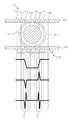
도 8은 본 발명의 일 실시예에 따른 수액 방울 검출 장치에서 수액 방울의 지름을 검출하는 방법을 설명하기 위한 그래프이다.8 is a graph for explaining a method of detecting the diameter of a droplet of a droplet in the droplet detecting apparatus according to an embodiment of the present invention.
도 8을 참조하면, 발광 센서(110)는 제1 광 송출부(111) 내지 제8 광 송출부(118)를 포함하여 점적 챔버(10)로 광 신호를 투과시킬 수 있으며, 수광 센서(120) 또한 제1 광 수신부(121) 내지 제8 광 수신부(128)를 포함하여 점적 챔버(10)를 투과하는 광 신호를 수신할 수 있다. 이때, 수액 방울 검출부(141)에 의해 수액 방울(21)이 검출될 수 있으며, 이러한 수액 방울(21)에 의해 제3 광 수신부(123) 내지 제6 광 수신부(126)는 광 신호를 수신할 수 없다.8, the
도 8의 첫 번째 그래프는 수액 방울(21)이 검출되는 시점에 수광 센서(120)로부터 출력되는 전기 신호를 나타낸 그래프이다. 구체적으로는, 수액 방울(21)이 검출되는 시점에 수광 센서(120)에 포함되는 복수의 광 수신부로부터 출력되는 전기 신호를 복수의 광 수신부가 배열된 순서대로 나열하고, 신호 처리부(130)에 의해 디지털 형태로 변환된 전기 신호를 나타낸 그래프이다. 수액 방울 크기 추출부(143)는 이러한 전기 신호를 도 8의 두 번째 및 세 번째 그래프와 같이 미분하여 변화가 급격한 부분을 수액 방울(21)의 에지(Edge)로 검출할 수 있다. 즉, 수액 방울 크기 추출부(143)는 수액 방울(21)로 검출된 전기 신호를 미분하여 신호 변화가 급격한 부분(a,b)을 검출하고, 해당 부분(a,b)를 수액 방울(21)의 에지(Edge)로 검출할 수 있다. 도 8에서는 전기 신호를 두 번 미분한 것을 예로 들어 도시하였으나 이에 한정하는 것은 아니다. 이때, 수액 방울 크기 추출부(143)는 두 개의 에지(Edge)를 검출하는 것이 바람직하다.The first graph in FIG. 8 is a graph showing an electrical signal output from the
또한, 수액 방울 크기 추출부(143)는 수광 센서(120)에 포함되는 복수의 광 수신부 중 수액 방울(21)의 에지(Edge)로 검출된 부분에 대응하는 광 수신부의 위치를 이용하여 수액 방울(21)의 지름을 산출할 수 있다. 수광 센서(120)에 포함되는 복수의 광 수신부는 동일한 간격으로 배열될 수 있으며, 복수의 광 수신부의 간격은 메모리부(160)에 저장될 수 있다. 따라서, 수액 방울 크기 추출부(143)는 수액 방울(21)의 에지(Edge)로 검출된 부분에 대응하는 광 수신부의 위치를 파악하고, 메모리부(160)에 저장된 수광 센서(120)의 간격 정보와 정합하여 두 개의 에지(Edge) 사이의 거리를 산출할 수 있다. 즉, 도 8에서는 수액 방울 크기 추출부(143)는 제3 광 수신부(123)와 제6 광 수신부(126) 사이의 거리를 수액 방울(21)의 지름으로 산출할 수 있다.The droplet size extracting unit 143 extracts droplets of droplets using the position of the light receiving unit corresponding to the portion of the plurality of light receiving units included in the
또한, 수액 방울 크기 추출부(143)는 산출한 수액 방울(21)의 지름을 이용하여 해당 수액 방울(21)의 부피를 산출할 수 있다. 이때, 수액 방울 크기 추출부(143)는 일반적인 구의 부피를 구하는 공식(
또는, 수액 방울 크기 추출부(143)는 수액 방울(21)이 검출되는 시점으로부터 미리 정해진 시간 동안 수액 방울(21)의 에지(Edge)를 검출하여 지름을 산출하고, 이를 이용하여 원의 단면적을 산출하는 과정을 반복 수행하고 미리 정해진 시간동안 산출한 원의 단면적을 적산하는 방식으로 수액 방울(21)의 부피를 산출할 수 있다.Alternatively, the droplet size extractor 143 may calculate the diameter of the
이에 더하여, 수액 방울 크기 추출부(143)는 수액 방울 검출부(141)에 의해 검출되는 수액 방울(21)을 계수하고, 산출한 수액 방울(21)의 부피를 곱하여 누적 수액 주입량을 산출할 수 있다. 이때, 수액 방울 크기 추출부(143)는 수액 방울 검출부(141)에 의해 수액 방울(21)이 검출될 때마다 수액 방울(21)의 부피를 산출하거나, 최초에 산출한 수액 방울(21)의 부피를 이용하여 누적 수액 주입량을 산출할 수 있다.In addition to this, the liquid droplet size extracting section 143 may count the
또한, 수액 방울 크기 추출부(143)는 미리 정해진 수액 주입량과 누적 수액 주입량을 비교하여 수액 주입이 완료되었는지 판단할 수 있다. 수액 방울 크기 추출부(143)는 간호사 또는 보호자로부터 입력부(미도시)를 통해 환자에게 주입하여야 하는 수액 주입량을 입력받을 수 있으며, 입력받은 수액 주입량과 산출한 누적 수액 주입량을 비교하여 수액 주입이 완료되었는지 판단할 수 있다.In addition, the droplet size extractor 143 may determine whether the infusion is completed by comparing the predetermined infusion volume and the infusion volume. The droplet size extracting unit 143 may receive the amount of the infusion fluid to be infused to the patient through an input unit (not shown) from the nurse or a caregiver. When the infusion amount of infusion fluid is compared with the infused infusion amount, .
또한, 수액 방울 크기 추출부(143)는 산출한 누적 수액 주입량을 미리 정해진 시간에 따라 또는 실시간으로 표시부(150)를 통해 출력할 수 있으며, 수액 주입이 완료되었다고 판단한 경우, 수액 주입 종료 알림을 표시부(150)를 통해 출력할 수 있다.In addition, the droplet size extracting unit 143 may output the calculated cumulative infusion volume through the
한편, 점적 챔버 기울기 추출부(144)는 수광 센서(120)에서 수신하는 복수의 광 신호의 변화량에 기반하여 점적 챔버(10)의 자세 변화 여부를 판단할 수 있다.On the other hand, the drip chamber slope extracting unit 144 can determine whether the
구체적으로는, 수광 센서(120)는 상술한 바와 같이 횡방향으로 배열된 복수의 광 수신부를 포함할 수 있으며, 제2 슬릿 기구(102)에 의해 점적 챔버(10)의 외측 타면을 향해 수직하게 배열되어, 점적 챔버(10)의 외측 일면에 존재하는 발광 센서(110)로부터 출력되는 광 신호를 수신할 수 있다. 즉, 점적 챔버(10)의 외측 양면에서 수광 센서(120)에 포함되는 복수의 광 수신부와 발광 센서(110)에 포함되는 복수의 광 송출부와 서로 대응되는 위치에 존재하므로, 수광 센서(120)로부터 출력되는 전기 신호는 양측이 대칭적인 형태로 출력될 수 있다. 이때, 점적 챔버(10)의 자세가 정상인 상태에서 수액팩(20)으로부터 점적 챔버(10)로 낙하하는 수액 방울(21)이 존재하는 경우, 수광 센서(120)에 포함되는 복수의 광 수신부 중 중심에 배열된 광 수신부로부터 출력되는 전기 신호의 변화량이 가장 큰 것이 바람직하다. 반면, 점적 챔버(10)가 기울어진 상태에서 수액팩(20)으로부터 점적 챔버(10)로 낙하하는 수액 방울(21)이 존재하는 경우, 수광 센서(120)에 포함되는 복수의 광 수신부 중 양 측 끝부분에 배열된 광 수신부로부터 출력되는 전기 신호의 변화량이 가장 크게 산출될 수 있다. 따라서, 점적 챔버 기울기 추출부(144)는 수광 센서(120)에 포함되는 각 광 수신부별로 연속해서 수신하는 신호의 변화량을 산출하거나, 수액 방울 검출부(141)에 의해 산출된 신호의 변화량을 이용하여 점적 챔버(10)의 자세 이상 여부를 판단할 수 있다. 이와 관련하여, 도 9를 참조하여 설명한다.Specifically, the
도 9는 본 발명의 일 실시예에 따른 수액 방울 검출 장치에서 점적 챔버의 자세 변화 여부를 판단하는 방법을 설명하기 위한 도면이다.FIG. 9 is a view for explaining a method for determining whether or not a posture chamber is changed in a droplet detecting apparatus according to an embodiment of the present invention.
먼저, 도 9의 (a)를 참조하면, 점적 챔버(10)의 자세가 정상인 상태에서는, 수액팩(20)으로부터 점적 챔버(10)로 낙하하는 수액 방울(21)의 낙하 궤적은 점적 챔버(10)의 중심축과 동일할 수 있다. 즉, 점적 챔버(10)의 자세가 정상인 경우, 점적 챔버(10)의 중심축은 중력 방향과 동일하므로, 수액팩(20)으로부터 중력 방향으로 낙하하는 수액 방울(21)은 점적 챔버(10)의 중심축을 따라 낙하할 수 있다. 이와 같은 경우, 수광 센서(120)에 포함되는 복수의 광 수신부 중 중심에 배열된 광 수신부(점적 챔버(10)의 중심축에 대응하는 위치에 배열된 광 수신부)로부터 출력되는 전기 신호의 변화량이 가장 크게 산출될 수 있으며, 따라서, 점적 챔버 기울기 추출부(144)는 점적 챔버(10)의 자세가 정상인 것으로 판단할 수 있다.9 (a), when the posture of the
반면, 도 9의 (b)를 참조하면, 점적 챔버(10)가 기울어진 상태에서는 수액팩(20)으로부터 점적 챔버(10)로 낙하하는 수액 방울(21)의 낙하 궤적은 점적 챔버(10)의 중심축과 소정의 각도(θ)를 가질 수 있다. 즉, 수액팩(20)으로부터 점적 챔버(10)로 낙하하는 수액 방울(21)은 점적 챔버(10)의 자세 변화와 무관하게 중력 방향으로 낙하하므로, 수액 방울(21)의 낙하 궤적과 점적 챔버(10)의 중심축이 이루는 각도(θ)는 중력 방향을 기준으로 점적 챔버(10)가 기울어진 각도를 의미할 수 있다. 이와 같은 경우, 수광 센서(120)에 포함되는 복수의 광 수신부 중, 중심에 배열된 광 수신부(점적 챔버(10)의 중심축에 대응하는 위치에 배열된 광 수신부)로부터 수액 방울(21)의 낙하 궤적과 점적 챔버(10)의 중심축이 이루는 각도(θ)와 대응하는 변위(d)만큼 이격된 위치에 배열되는 광 수신부에서 출력되는 전기 신호의 변화량이 가장 크게 산출될 수 있으며, 따라서, 점적 챔버 기울기 추출부(144)는 점적 챔버(10)의 수광 센서(120)에 포함되는 복수의 광 수신부 중 출력하는 전기 신호의 변화량이 가장 큰 광 수신부가 배열된 위치에 따라 중력 방향을 기준으로 점적 챔버(10)가 기울어진 방향을 추출하고, 점적 챔버(10)의 자세가 비정상인 것으로 판단할 수 있다. 이때, 수광 센서(120)에 포함되는 복수의 광 수신부가 배열된 위치 정보는 복수의 광 수신부별로 식별번호가 부여되어 메모리부(160)에 저장될 수 있다.9 (b), the droplet trajectory of the
또한, 점적 챔버 기울기 추출부(144)는 점적 챔버(10)의 자세가 비정상인 것으로 판단하면 표시부(150)를 통해 해당 정보를 출력할 수 있다.The drip chamber slope extractor 144 may output the information through the
한편, 표시부(150)는 상술한 바와 같이 제어부(140)에 의해 수액 주입 속도, 수액 주입 이상상황, 누적 수액 주입량, 수액 주입 종료 여부, 점적 챔버(10)의 자세 이상 여부 등을 출력할 수 있으며, 이를 위해, 표시부(150)는 디스플레이 또는 음향 출력 모듈을 포함할 수 있다.On the other hand, as described above, the
또한, 메모리부(160)는 수액 방울 검출 장치(100)의 처리 및 제어를 위한 프로그램이 저장될 수 있으며, 입/출력되는 데이터들의 임시 저장을 위한 기능을 수행할 수 있다. 특히, 메모리부(160)는 수광 센서(120)에 포함되는 복수의 광 수신부의 배열 간격이 저장될 수 있으며, 복수의 광 수신부별로 식별번호가 부여되고 식별번호와 배열된 위치 정보가 매칭되어 저장될 수 있다.In addition, the
이와 같이, 본 발명의 일 실시예에 따른 수액 방울 검출 장치(100)는 횡방향으로 배열된 복수의 광 송출부를 포함하는 발광 센서(110) 및 횡방향으로 배열된 복수의 광 수신부를 포함하는 수광 센서(120)로 구성됨으로써, 수광 센서(120)로부터 출력되는 복수의 전기 신호에 기반하여 수액팩(20)으로부터 점적 챔버(10)로 낙하하는 수액 방울(21)을 검출할 뿐만 아니라. 수액 방울(21)의 지름을 산출하여 점적 챔버(10)의 기구적 특성 또는 외부 환경적 요인에 관계 없이 수액 방울(21)의 부피를 산출할 수 있으며, 이는 누적 수액량을 산출하는 데 있어서 정확도를 높일 수 있다. 이에 더하여, 본 발명의 일 실시예에 따른 수액 방울 검출 장치(100)는 수광 센서(120)로부터 출력되는 복수의 전기 신호에 기반하여 점적 챔버(10)의 자세 이상 여부를 검출할 수 있으므로, 보다 안전하고 정확하게 수액을 주입할 수 있다.As described above, the
이하에서는, 도 10을 참조하여 본 발명의 일 실시예에 따른 수액 방울 검출 방법을 설명한다.Hereinafter, a method of detecting a droplet of a droplet according to an embodiment of the present invention will be described with reference to FIG.
도 10은 본 발명의 일 실시예에 따른 수액 방울 검출 방법을 설명하기 위한 도면이다.FIG. 10 is a view for explaining a method for detecting a droplet according to an embodiment of the present invention.
본 발명의 일 실시예에 따른 수액 방울 검출 방법은 도 5에 도시된 수액 방울 검출 장치(100)와 실질적으로 동일한 구성에서 진행될 수 있다. 따라서, 도 5의 수액 방울 검출 장치(100)와 동일한 구성요소는 동일한 도면부호를 부여하고, 반복되는 설명은 생략한다.The droplet detection method according to an embodiment of the present invention can be performed in substantially the same configuration as the
본 발명의 일 실시예에 따른 수액 방울 검출 방법은, 먼저, 센서 거치 기구(100a)가 점적 챔버(10)에 장착되었는지 판단할 수 있다(200). 제어부(140)는 센서 거치 기구(100a)와 전기적으로 연결되어 센서 거치 기구(100a)가 점적 챔버(10)에 장착되는지 여부를 판단할 수 있다.The droplet detecting method according to an embodiment of the present invention may first determine whether the
센서 거치 기구(100a)가 점적 챔버(10)에 장착된 경우, 발광 센서(110)로부터 점적 챔버(10)로 복수의 광 신호를 출력하고, 수광 센서(120)에서는 점적 챔버(10)를 투과한 복수의 광 신호를 수신할 수 있다(210).The
발광 센서(110) 및 수광 센서(120)는 제1 슬릿 기구(101) 및 제2 슬릿 기구(102)에 의해 점적 챔버(10)를 사이에 두고 양 측면에서 서로 마주보며 대칭되게 배치될 수 있으며, 발광 센서(110)는 횡방향으로 배열된 복수의 광 송출부로 구성되고, 수광 센서(120)는 횡방향으로 배열된 복수의 광 수신부로 구성될 수 있다. 이에 따라, 발광 센서(110)로부터 출력되는 복수의 광 신호는 점적 챔버(10)를 투과하여 수광 센서(120)로 입력될 수 있다. 또한, 수광 센서(120)로 입력된 복수의 광 신호는 소정의 신호 처리를 거쳐 제어부(140)로 전달될 수 있다.The
제어부(140)는 점적 챔버(10)로 낙하하는 수액 방울(21) 검출을 위한 임계치를 설정할 수 있다(220). 일반적으로, 센서 거치 기구(100a)는 수액의 주입이 시작되는 경우 점적 챔버(10)에 장착되므로, 센서 거치 기구(100a)가 점적 챔버(10)에 장착되는 시점에서는 수액 방울(21)이 낙하하기 전 또는 낙하하지 않은 상태이며, 따라서, 수액 방울 검출부(141)는 센서 거치 기구(100a)가 점적 챔버(10)에 장착되는 시점에 수광 센서(120)로부터 출력되는 복수의 전기 신호의 크기를 산출하여 임계치로 설정할 수 있다.The
이후, 제어부(140)는 수광 센서(120)에서 연속하여 수신하는 복수의 광 신호의 변화량이 임계치보다 크거나 같은지 판단할 수 있다(230). 즉, 제어부(140)는 수광 센서(120)에서 연속하여 수신하는 복수의 광 신호의 변화량과 임계치를 비교하여 수액팩(20)으로부터 점적 챔버(10)로 낙하하는 수액 방울(21)이 존재하는지 여부를 판단할 수 있다.Thereafter, the
여기에서, 제어부(140)는 수광 센서(120)에서 연속하여 수신하는 복수의 광 신호의 변화량이 임계치보다 크거나 같은 경우, 수액팩(20)으로부터 점적 챔버(10)로 낙하하는 수액 방울(21)이 존재하는 것으로 판단할 수 있다.Here, when the amount of change of the plurality of optical signals continuously received by the
또한, 제어부(140)는 해당 수액 방울(21)의 낙하 속도를 산출하여 평균 낙하 속도와 비교하고(240), 수액 방울(21)의 낙하 속도가 정상이 아닌 것으로 판단되면(250) 알람 경고를 출력할 수 있다(255). 제어부(140)는 연속하여 낙하하는 수액 방울(21)의 검출 시간 간격에 따라 수액 방울(21)의 낙하 속도를 산출할 수 있으며, 평균 낙하 속도는 미리 설정되거나, 연속하여 검출되는 n개의 수액 방울(21)의 평균 낙하 속도이거나, 미리 정해진 시간동안 검출되는 수액 방울(21)의 평균 낙하 속도일 수 있다.The
또한, 제어부(140)는 해당 수액 방울(21)의 크기 정보를 추출할 수 있으며(260), 수액 방울(21)의 크기 정보를 적산하여 누적 수액 주입량을 산출할 수 있다(270).The
구체적으로는, 제어부(140)는 수광 센서(120)에서 수신하는 복수의 광 신호를 미분하여 복수의 광 신호 간의 변화가 급격한 부분을 수액 방울(21)의 에지로 검출할 수 있다. 그리고, 제어부(140)는 수광 센서(120)에 포함되는 복수의 광 수신부 중 에지로 검출된 부분에 대응하는 광 수신부의 위치와 복수의 광 수신부 간의 간격 정보를 정합하여 수액 방울(21)의 지름을 산출하고, 수액 방울(21)의 지름에 따라 수액 방울(21)의 부피를 산출할 수 있다. 그리고, 수액 방울 검출 장치(100)가 구동되는 동안 산출한 수액 방울(21)의 부피를 적산하여 누적 수액 주입량을 산출할 수 있다.More specifically, the
또한, 제어부(140)는 누적 수액 주입량과 미리 정해진 수액 주입량을 비교할 수 있다(280). 여기서, 미리 정해진 수액 주입량은 간호사 또는 보호자로부터 수액 주입 전 입력받은 수치일 수 있다.In addition, the
제어부(140)는 누적 수액 주입량이 미리 정해진 수액 주입량보다 적은 것으로 판단한 경우, 제어부(140)는 수광 센서(120)에서 연속하여 수신하는 복수의 광 신호의 변화량이 임계치보다 크거나 같은지 판단(230)하는 과정을 다시 수행할 수 있다.If the
반면, 제어부(140)는 누적 수액 주입량이 미리 정해진 수액 주입량보다 많거나 같은 것으로 판단한 경우, 수액 주입 종료 알림을 출력할 수 있다(290).On the other hand, if the
한편, 도 11은 본 발명의 다른 실시예에 따른 수액 방울 검출 방법을 설명하기 위한 도면이다.11 is a view for explaining a method of detecting a droplet according to another embodiment of the present invention.
본 발명의 다른 실시예에 따른 수액 방울 검출 방법은 도 10에 도시된 본 발명의 일 실시예에 따른 수액 방울 검출 방법과 동일하며, 점적 챔버(10)의 자세 변화 여부를 검출하는 단계를 더 포함할 수 있다.The method for detecting a droplet according to another embodiment of the present invention is the same as the method for detecting a droplet according to an embodiment of the present invention shown in FIG. 10, and further includes a step of detecting whether the posture of the
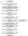
본 발명의 다른 실시예에 따른 수액 방울 검출 방법은, 먼저, 센서 거치 기구(100a)가 점적 챔버(10)에 장착되었는지 판단할 수 있다(300). 제어부(140)는 센서 거치 기구(100a)와 전기적으로 연결되어 센서 거치 기구(100a)가 점적 챔버(10)에 장착되는지 여부를 판단할 수 있다.The droplet sensing method according to another embodiment of the present invention may first determine whether the
센서 거치 기구(100a)가 점적 챔버(10)에 장착된 경우, 발광 센서(110)로부터 점적 챔버(10)로 복수의 광 신호를 출력하고, 수광 센서(120)에서는 점적 챔버(10)를 투과한 복수의 광 신호를 수신할 수 있다(310).The
발광 센서(110) 및 수광 센서(120)는 제1 슬릿 기구(101) 및 제2 슬릿 기구(102)에 의해 점적 챔버(10)를 사이에 두고 양 측면에서 서로 마주보며 대칭되게 배치될 수 있으며, 발광 센서(110)는 횡방향으로 배열된 복수의 광 송출부로 구성되고, 수광 센서(120)는 횡방향으로 배열된 복수의 광 수신부로 구성될 수 있다. 이에 따라, 발광 센서(110)로부터 출력되는 복수의 광 신호는 점적 챔버(10)를 투과하여 수광 센서(120)로 입력될 수 있다. 또한, 수광 센서(120)로 입력된 복수의 광 신호는 소정의 신호 처리를 거쳐 제어부(140)로 전달될 수 있다.The
제어부(140)는 점적 챔버(10)로 낙하하는 수액 방울(21) 검출을 위한 임계치를 설정할 수 있다(320). 일반적으로, 센서 거치 기구(100a)는 수액의 주입이 시작되는 경우 점적 챔버(10)에 장착되므로, 센서 거치 기구(100a)가 점적 챔버(10)에 장착되는 시점에서는 수액 방울(21)이 낙하하기 전 또는 낙하하지 않은 상태이며, 따라서, 수액 방울 검출부(141)는 센서 거치 기구(100a)가 점적 챔버(10)에 장착되는 시점에 수광 센서(120)로부터 출력되는 복수의 전기 신호의 크기를 산출하여 임계치로 설정할 수 있다.The
이후, 제어부(140)는 수광 센서(120)에서 연속하여 수신하는 복수의 광 신호의 변화량이 임계치보다 크거나 같은지 판단할 수 있다(330). 즉, 제어부(140)는 수광 센서(120)에서 연속하여 수신하는 복수의 광 신호의 변화량과 임계치를 비교하여 수액팩(20)으로부터 점적 챔버(10)로 낙하하는 수액 방울(21)이 존재하는지 여부를 판단할 수 있다.Thereafter, the
여기에서, 제어부(140)는 수광 센서(120)에서 연속하여 수신하는 복수의 광 신호의 변화량이 임계치보다 크거나 같은 경우, 수액팩(20)으로부터 점적 챔버(10)로 낙하하는 수액 방울(21)이 존재하는 것으로 판단할 수 있다.Here, when the amount of change of the plurality of optical signals continuously received by the
또한, 제어부(140)는 해당 수액 방울(21)의 낙하 속도를 산출하여 평균 낙하 속도와 비교하고(340), 수액 방울(21)의 낙하 속도가 정상이 아닌 것으로 판단되면(350) 알람 경고를 출력할 수 있다(355). 제어부(140)는 연속하여 낙하하는 수액 방울(21)의 검출 시간 간격에 따라 수액 방울(21)의 낙하 속도를 산출할 수 있으며, 평균 낙하 속도는 미리 설정되거나, 연속하여 검출되는 n개의 수액 방울(21)의 평균 낙하 속도이거나, 미리 정해진 시간동안 검출되는 수액 방울(21)의 평균 낙하 속도일 수 있다.The
또한, 제어부(140)는 점적 챔버(10)의 기울기 정보를 추출하여 점적 챔버(10)의 자세 이상 여부를 판단할 수 있다(360). 제어부(140)는 수광 센서(120)에 포함되는 복수의 광 수신부별로 연속하여 수신하는 광 신호의 변화량을 산출하고, 복수의 광 수신부 중 변화량이 가장 큰 광 수신부의 위치에 따라 점적 챔버(10)의 기울기 정보를 추출하여, 점적 챔버(10)의 자세가 변화하였는지 판단할 수 있다.In addition, the
이때, 제어부(140)는 점적 챔버(10)의 자세가 변한 것으로 판단하면(370), 알람 경고를 출력할 수 있다(375).At this time, if the
또한, 제어부(140)는 해당 수액 방울(21)의 크기 정보를 추출할 수 있으며(380), 수액 방울(21)의 크기 정보를 적산하여 누적 수액 주입량을 산출할 수 있다(385).The
구체적으로는, 제어부(140)는 수광 센서(120)에서 수신하는 복수의 광 신호를 미분하여 복수의 광 신호 간의 변화가 급격한 부분을 수액 방울(21)의 에지로 검출할 수 있다. 그리고, 제어부(140)는 수광 센서(120)에 포함되는 복수의 광 수신부 중 에지로 검출된 부분에 대응하는 광 수신부의 위치와 복수의 광 수신부 간의 간격 정보를 정합하여 수액 방울(21)의 지름을 산출하고, 수액 방울(21)의 지름에 따라 수액 방울(21)의 부피를 산출할 수 있다. 그리고, 수액 방울 검출 장치(100)가 구동되는 동안 산출한 수액 방울(21)의 부피를 적산하여 누적 수액 주입량을 산출할 수 있다.More specifically, the
또한, 제어부(140)는 누적 수액 주입량과 미리 정해진 수액 주입량을 비교할 수 있다(390). 여기서, 미리 정해진 수액 주입량은 간호사 또는 보호자로부터 수액 주입 전 입력받은 수치일 수 있다.In addition, the
제어부(140)는 누적 수액 주입량이 미리 정해진 수액 주입량보다 적은 것으로 판단한 경우, 제어부(140)는 수광 센서(120)에서 연속하여 수신하는 복수의 광 신호의 변화량이 임계치보다 크거나 같은지 판단(330)하는 과정을 다시 수행할 수 있다.If the
반면, 제어부(140)는 누적 수액 주입량이 미리 정해진 수액 주입량보다 많거나 같은 것으로 판단한 경우, 수액 주입 종료 알림을 출력할 수 있다(395).On the other hand, if the
이와 같은, 수액 방울 검출 방법은 애플리케이션으로 구현되거나 다양한 컴퓨터 구성요소를 통하여 수행될 수 있는 프로그램 명령어의 형태로 구현되어 컴퓨터 판독 가능한 기록 매체에 기록될 수 있다. 상기 컴퓨터 판독 가능한 기록 매체는 프로그램 명령어, 데이터 파일, 데이터 구조 등을 단독으로 또는 조합하여 포함할 수 있다.Such a droplet detection method can be implemented in an application or can be implemented in the form of program instructions that can be executed through various computer components and recorded on a computer-readable recording medium. The computer-readable recording medium may include program commands, data files, data structures, and the like, alone or in combination.
상기 컴퓨터 판독 가능한 기록 매체에 기록되는 프로그램 명령어는 본 발명을 위하여 특별히 설계되고 구성된 것들이거니와 컴퓨터 소프트웨어 분야의 당업자에게 공지되어 사용 가능한 것일 수도 있다.The program instructions recorded on the computer-readable recording medium may be ones that are specially designed and configured for the present invention and are known and available to those skilled in the art of computer software.
컴퓨터 판독 가능한 기록 매체의 예에는, 하드 디스크, 플로피 디스크 및 자기 테이프와 같은 자기 매체, CD-ROM, DVD 와 같은 광기록 매체, 플롭티컬 디스크(floptical disk)와 같은 자기-광 매체(magneto-optical media), 및 ROM, RAM, 플래시 메모리 등과 같은 프로그램 명령어를 저장하고 수행하도록 특별히 구성된 하드웨어 장치가 포함된다.Examples of computer-readable recording media include magnetic media such as hard disks, floppy disks and magnetic tape, optical recording media such as CD-ROMs and DVDs, magneto-optical media such as floptical disks, media, and hardware devices specifically configured to store and execute program instructions such as ROM, RAM, flash memory, and the like.
프로그램 명령어의 예에는, 컴파일러에 의해 만들어지는 것과 같은 기계어 코드 뿐만 아니라 인터프리터 등을 사용해서 컴퓨터에 의해서 실행될 수 있는 고급 언어 코드도 포함된다. 상기 하드웨어 장치는 본 발명에 따른 처리를 수행하기 위해 하나 이상의 소프트웨어 모듈로서 작동하도록 구성될 수 있으며, 그 역도 마찬가지이다.Examples of program instructions include machine language code such as those generated by a compiler, as well as high-level language code that can be executed by a computer using an interpreter or the like. The hardware device may be configured to operate as one or more software modules for performing the processing according to the present invention, and vice versa.
이상에서는 실시예들을 참조하여 설명하였지만, 해당 기술 분야의 숙련된 당업자는 하기의 특허 청구범위에 기재된 본 발명의 사상 및 영역으로부터 벗어나지 않는 범위 내에서 본 발명을 다양하게 수정 및 변경시킬 수 있음을 이해할 수 있을 것이다.While the present invention has been particularly shown and described with reference to exemplary embodiments thereof, it will be understood by those skilled in the art that various changes and modifications may be made therein without departing from the spirit and scope of the invention as defined in the appended claims. It will be possible.
10: 점적 챔버100: 수액 방울 검출 장치
20: 수액팩100a: 센서 거치 기구
21: 수액 방울100b: 제어 기구
30: 조절기101: 제1 슬릿 기구
40: 호스102: 제2 슬릿 기구
50: 주사 바늘110: 발광 센서
60: 거치대120: 수광 센서10: drip chamber 100: liquid drop detection device
20:
21:
30: regulator 101: first slit mechanism
40: Hose 102: Second slit mechanism
50: injection needle 110: light emission sensor
60: Cradle 120: Light receiving sensor
Claims (19)
Translated fromKorean상기 점적 챔버의 외측 일면을 향하여 배치되는 복수의 광 송출부를 포함하고, 상기 복수의 광 송출부를 통해 복수의 광 신호를 상기 점적 챔버로 투과시키는 발광 센서;
상기 점적 챔버의 외측 타면을 향하여 배치되는 복수의 광 수신부를 포함하고, 상기 복수의 광 수신부를 통해 상기 점적 챔버로 투과되는 상기 복수의 광 신호를 수신하는 수광 센서; 및
상기 수광 센서에서 수신하는 복수의 광 신호에 따라 상기 수액팩으로부터 상기 점적 챔버로 낙하하는 상기 수액 방울을 검출하고, 상기 수액 방울의 크기 정보와 상기 점적 챔버의 기울기 정보를 추출하는 제어부를 포함하되,
상기 제어부가 상기 수광 센서에서 수신하는 복수의 광 신호에 따라 상기 수액 방울의 크기 정보와 점적 챔버의 기울기 정보를 추출하는 것은,
상기 수광 센서에서 포함되는 상기 복수의 광 수신부별로 연속하여 수신하는 광 신호의 변화량을 산출하고, 상기 복수의 광 수신부 중 상기 변화량이 가장 큰 광 수신부의 위치에 따라 상기 점적 챔버의 기울기 정보를 추출하는 것인 수액 방울 검출 장치.A liquid droplet detecting apparatus for detecting liquid droplets falling from a liquid solution pack into a drop chamber,
A light emitting sensor including a plurality of light emitting units disposed toward an outer side of the drip chamber and transmitting a plurality of optical signals to the drip chamber through the plurality of light emitting units;
A light receiving sensor for receiving the plurality of optical signals transmitted through the plurality of light receiving portions to the drip chamber, the plurality of light receiving portions being disposed toward the other outer side of the drip chamber; And
And a controller for detecting the droplet dropping from the liquid infiltration pack into the drip chamber according to a plurality of optical signals received by the light receiving sensor and extracting the size information of the droplet and the tilt information of the drip chamber,
Extracting the size information of the liquid droplet and the slope information of the drop chamber according to a plurality of optical signals received by the light receiving sensor,
Calculating a change amount of an optical signal continuously received for each of the plurality of light receiving units included in the light receiving sensor and extracting tilt information of the drop chamber according to a position of the light receiving unit having the largest change amount among the plurality of light receiving units Wherein the liquid droplet detecting device is a liquid droplet detecting device.
상기 제어부가 상기 수광 센서에서 수신하는 복수의 광 신호에 따라 상기 수액팩으로부터 상기 점적 챔버로 낙하하는 상기 수액 방울을 검출하는 것은,
상기 수광 센서에서 연속하여 수신하는 복수의 광 신호의 변화량을 산출하고, 산출한 변화량과 임계치를 비교하여 상기 수액 방울을 검출하는 것인 수액 방울 검출 장치.The method according to claim 1,
The control unit detects the liquid drop falling from the liquid receiver pack to the drip chamber according to a plurality of optical signals received by the light receiving sensor,
Wherein the amount of change of the plurality of optical signals continuously received by the light receiving sensor is calculated, and the calculated amount of change is compared with a threshold value to detect the liquid drop.
상기 제어부가 상기 수광 센서에서 수신하는 복수의 광 신호에 따라 상기 수액 방울의 크기 정보 또는 상기 점적 챔버의 기울기 정보를 추출하는 것은,
상기 수광 센서에서 수신하는 복수의 광 신호를 미분하여 상기 복수의 광 신호 간의 변화가 급격한 부분을 상기 수액 방울의 에지로 검출하는 것을 포함하는 수액 방울 검출 장치.The method according to claim 1,
Extracting the size information of the liquid droplet or the tilt information of the drip chamber according to a plurality of optical signals received by the control unit from the light receiving sensor,
And a plurality of optical signals received by the light receiving sensor are differentiated to detect an abrupt change in the optical signal among the plurality of optical signals as an edge of the liquid droplet.
상기 제어부가 상기 수광 센서에서 수신하는 복수의 광 신호에 따라 상기 수액 방울의 크기 정보 또는 상기 점적 챔버의 기울기 정보를 추출하는 것은,
상기 수광 센서에 포함되는 상기 복수의 광 수신부 중 상기 에지로 검출된 부분에 대응하는 광 수신부의 위치와 상기 복수의 광 수신부 간의 간격 정보를 정합하여 상기 수액 방울의 지름을 산출하고, 상기 수액 방울의 지름에 따라 상기 수액 방울의 크기 정보를 추출하는 것을 포함하는 수액 방울 검출 장치.The method of claim 3,
Extracting the size information of the liquid droplet or the tilt information of the drip chamber according to a plurality of optical signals received by the control unit from the light receiving sensor,
Calculating a diameter of the liquid droplet by matching the position of the light receiving portion corresponding to the portion detected by the edge among the plurality of light receiving portions included in the light receiving sensor and the interval information between the plurality of light receiving portions, And extracting the size information of the droplet according to the diameter of the droplet.
상기 제어부는,
상기 수액 방울의 크기 정보에 기반하여 누적 수액 주입량을 산출하는 것을 더 포함하는 수액 방울 검출 장치.The method according to claim 1,
Wherein,
Further comprising calculating a cumulative amount of injected liquid based on the size information of the liquid droplet.
상기 제어부는,
상기 수액 방울이 검출되는 시간 간격에 따라 수액 주입 속도를 산출하고, 이에 기반하여 수액 주입 이상상황을 판단하는 것을 더 포함하는 수액 방울 검출 장치.The method according to claim 1,
Wherein,
Further comprising: calculating a liquid infusion rate according to a time interval at which the liquid droplet is detected, and determining a liquid infusion abnormal condition based on the calculated liquid infusion rate.
상기 발광 센서는,
상기 점적 챔버의 외측 일면과 맞닿을 수 있도록 상기 점적 챔버에 장착되는 센서 거치 기구에 장착되는 수액 방울 검출 장치.The method according to claim 1,
The light-
And is attached to a sensor mounting mechanism mounted on the drip chamber so as to abut on the outer side of the drip chamber.
상기 수광 센서는,
상기 점적 챔버의 외측 타면과 맞닿을 수 있도록 상기 점적 챔버에 장착되는 센서 거치 기구에 장착되는 수액 방울 검출 장치.The method according to claim 1,
The light-
And is attached to a sensor mounting mechanism mounted on the drip chamber so as to be able to come into contact with the other outside surface of the drip chamber.
상기 점적 챔버의 외측 일면을 향하여 배치되는 복수의 광 송출부를 통해 복수의 광 신호를 상기 점적 챔버로 투과시키고,
상기 점적 챔버의 외측 타면을 향하여 배치되는 복수의 광 수신부를 통해 상기 점적 챔버로 투과되는 상기 복수의 광 신호를 수신하고,
상기 복수의 광 수신부를 통해 수신하는 복수의 광 신호에 따라 상기 수액팩으로부터 상기 점적 챔버로 낙하하는 상기 수액 방울을 검출하고, 상기 수액 방울의 크기 정보와 상기 점적 챔버의 기울기 정보를 추출하되, 상기 복수의 광 수신부를 통해 수신하는 복수의 광 신호에 따라 상기 수액 방울의 크기 정보와 상기 점적 챔버의 기울기 정보를 추출하는 것은,
상기 복수의 광 수신부별로 연속하여 수신하는 광 신호의 변화량을 산출하고, 상기 복수의 광 수신부 중 상기 변화량이 가장 큰 광 수신부의 위치에 따라 상기 점적 챔버의 기울기 정보를 추출하는 것인 수액 방울 검출 방법.A liquid droplet detecting method for detecting a liquid droplet falling from a liquid infusion chamber into a drip chamber,
Transmitting a plurality of optical signals to the drip chamber through a plurality of light emitting units disposed toward the outer side of the drip chamber,
Receiving the plurality of optical signals transmitted to the drip chamber through a plurality of light receiving portions disposed toward the other outer side of the drip chamber,
Detecting the droplet falling from the liquid infiltration pump into the drip chamber according to a plurality of optical signals received through the plurality of light receiving units, extracting size information of the liquid droplet and tilt information of the drip chamber, Extracting the size information of the liquid droplet and the slope information of the drip chamber according to a plurality of optical signals received through the plurality of light receiving units,
Wherein the change amount of the optical signal continuously received for each of the plurality of light receiving units is calculated and the inclination information of the drop chamber is extracted according to the position of the light receiving unit having the largest change amount among the plurality of light receiving units .
상기 복수의 광 수신부를 통해 수신하는 복수의 광 신호에 따라 상기 수액팩으로부터 상기 점적 챔버로 낙하하는 상기 수액 방울을 검출하는 것은,
상기 복수의 광 수신부를 통해 연속하여 수신하는 복수의 광 신호의 변화량을 산출하고, 산출한 변화량과 임계치를 비교하여 상기 수액 방울을 검출하는 것인 수액 방울 검출 방법.11. The method of claim 10,
Detecting the drop of the liquid drop from the liquid receiver pack into the drip chamber according to a plurality of optical signals received through the plurality of light receiving sections,
Wherein a change amount of a plurality of optical signals continuously received through the plurality of light receiving sections is calculated and the calculated change amount is compared with a threshold value to detect the liquid drop.
상기 복수의 광 수신부를 통해 수신하는 복수의 광 신호에 따라 상기 수액 방울의 크기 정보 또는 상기 점적 챔버의 기울기 정보를 추출하는 것은,
상기 복수의 광 수신부를 통해 수신하는 복수의 광 신호를 미분하여 상기 복수의 광 신호 간의 변화가 급격한 부분을 상기 수액 방울의 에지로 검출하는 것을 포함하는 수액 방울 검출 방법.11. The method of claim 10,
Extracting the size information of the liquid droplet or the slope information of the drip chamber according to a plurality of optical signals received through the plurality of light receiving units,
And detecting an abrupt change in the optical signal among the plurality of optical signals as an edge of the droplet by differentiating a plurality of optical signals received through the plurality of optical receivers.
상기 복수의 광 수신부를 통해 수신하는 복수의 광 신호에 따라 상기 수액 방울의 크기 정보 또는 상기 점적 챔버의 기울기 정보를 추출하는 것은,
상기 복수의 광 수신부 중 상기 에지로 검출된 부분에 대응하는 광 수신부의 위치와 상기 복수의 광 수신부 간의 간격 정보를 정합하여 상기 수액 방울의 지름을 산출하고, 상기 수액 방울의 지름에 따라 상기 수액 방울의 크기 정보를 추출하는 것을 포함하는 수액 방울 검출 방법.13. The method of claim 12,
Extracting the size information of the liquid droplet or the slope information of the drip chamber according to a plurality of optical signals received through the plurality of light receiving units,
Calculating a diameter of the droplet by matching the position of the light receiving portion corresponding to the portion detected by the edge among the plurality of light receiving portions and the gap information between the plurality of light receiving portions, And extracting size information of the liquid droplet.
상기 수액 방울의 크기 정보에 기반하여 누적 수액 주입량을 산출하는 것을 더 포함하는 수액 방울 검출 방법.11. The method of claim 10,
Further comprising calculating a cumulative amount of injected liquid based on the size information of the liquid droplet.
상기 수액 방울이 검출되는 시간 간격에 따라 수액 주입 속도를 산출하고, 이에 기반하여 수액 주입 이상상황을 판단하는 것을 더 포함하는 수액 방울 검출 방법.11. The method of claim 10,
Further comprising: calculating a liquid infusion rate according to a time interval at which the liquid droplet is detected; and determining a liquid infusion abnormal condition based on the calculated liquid infusion rate.
상기 점적 챔버의 외측 일면을 향하여 배치되는 복수의 광 송출부를 통해 복수의 광 신호를 상기 점적 챔버로 투과시키는 것은,
상기 점적 챔버의 외측 일면과 맞닿을 수 있도록 상기 점적 챔버에 장착되는 복수의 광 송출부를 포함하는 발광 센서를 통해 복수의 광 신호를 상기 점적 챔버로 투과시키는 것인 수액 방울 검출 방법.11. The method of claim 10,
Transmitting a plurality of optical signals to the drip chamber through a plurality of light emitting units disposed toward the outer side of the drip chamber,
Wherein a plurality of optical signals are transmitted to the drip chamber through a light emitting sensor including a plurality of light emitting units mounted in the drip chamber so as to be able to come into contact with an outer side of the drip chamber.
상기 점적 챔버의 외측 타면을 향하여 배치되는 복수의 광 수신부를 통해 상기 점적 챔버로 투과되는 상기 복수의 광 신호를 수신하는 것은,
상기 점적 챔버의 외측 타면과 맞닿을 수 있도록 상기 점적 챔버에 장착되는 복수의 광 수신부를 포함하는 수광 센서를 통해 상기 복수의 광 신호를 수신하는 것인 수액 방울 검출 방법.11. The method of claim 10,
Receiving the plurality of optical signals transmitted through the plurality of light receiving portions disposed toward the other outer side of the drip chamber into the drip chamber,
Wherein the plurality of optical signals are received through a light receiving sensor including a plurality of light receiving portions mounted in the drip chamber so as to be able to come into contact with the other outside face of the drip chamber.
Priority Applications (1)
| Application Number | Priority Date | Filing Date | Title |
|---|---|---|---|
| KR1020150168249AKR101751395B1 (en) | 2015-11-30 | 2015-11-30 | Apparatus and method for ringer drop detection, recording medium for performing the method |
Applications Claiming Priority (1)
| Application Number | Priority Date | Filing Date | Title |
|---|---|---|---|
| KR1020150168249AKR101751395B1 (en) | 2015-11-30 | 2015-11-30 | Apparatus and method for ringer drop detection, recording medium for performing the method |
Publications (2)
| Publication Number | Publication Date |
|---|---|
| KR20170062718A KR20170062718A (en) | 2017-06-08 |
| KR101751395B1true KR101751395B1 (en) | 2017-06-27 |
Family
ID=59220986
Family Applications (1)
| Application Number | Title | Priority Date | Filing Date |
|---|---|---|---|
| KR1020150168249AActiveKR101751395B1 (en) | 2015-11-30 | 2015-11-30 | Apparatus and method for ringer drop detection, recording medium for performing the method |
Country Status (1)
| Country | Link |
|---|---|
| KR (1) | KR101751395B1 (en) |
Cited By (1)
| Publication number | Priority date | Publication date | Assignee | Title |
|---|---|---|---|---|
| WO2021080065A1 (en)* | 2019-10-25 | 2021-04-29 | 주식회사 메디유케어 | Device for automatically controlling infusion solution |
Families Citing this family (5)
| Publication number | Priority date | Publication date | Assignee | Title |
|---|---|---|---|---|
| KR102128058B1 (en)* | 2018-08-16 | 2020-06-30 | 주식회사 라이튼테크놀로지 | Fluid drops detecting apparatus and method |
| WO2020122118A1 (en) | 2018-12-14 | 2020-06-18 | 出光興産株式会社 | Organic electroluminescent element, compound, material for organic electroluminescent element, and electronic device |
| WO2021209653A1 (en)* | 2020-04-17 | 2021-10-21 | Adventia Pharma, S.L. | Device and method for monitoring the flow rate of a fluid in a drip chamber |
| KR102359375B1 (en)* | 2021-06-21 | 2022-02-08 | (주)신성테크 | Fluid monitoring device, method and system |
| KR102613023B1 (en)* | 2022-10-25 | 2023-12-12 | 에이스헬스케어(주) | Auto clamp for precise detection of flow |
Citations (2)
| Publication number | Priority date | Publication date | Assignee | Title |
|---|---|---|---|---|
| JP2011062371A (en)* | 2009-09-17 | 2011-03-31 | Terumo Corp | Drip-feed detector, infusion pump and method for controlling the same |
| US20130085443A1 (en)* | 2011-09-30 | 2013-04-04 | Michael G. Lowery | Intravenous Flow Rate Controller |
- 2015
- 2015-11-30KRKR1020150168249Apatent/KR101751395B1/enactiveActive
Patent Citations (2)
| Publication number | Priority date | Publication date | Assignee | Title |
|---|---|---|---|---|
| JP2011062371A (en)* | 2009-09-17 | 2011-03-31 | Terumo Corp | Drip-feed detector, infusion pump and method for controlling the same |
| US20130085443A1 (en)* | 2011-09-30 | 2013-04-04 | Michael G. Lowery | Intravenous Flow Rate Controller |
Cited By (1)
| Publication number | Priority date | Publication date | Assignee | Title |
|---|---|---|---|---|
| WO2021080065A1 (en)* | 2019-10-25 | 2021-04-29 | 주식회사 메디유케어 | Device for automatically controlling infusion solution |
Also Published As
| Publication number | Publication date |
|---|---|
| KR20170062718A (en) | 2017-06-08 |
Similar Documents
| Publication | Publication Date | Title |
|---|---|---|
| KR101751395B1 (en) | Apparatus and method for ringer drop detection, recording medium for performing the method | |
| US9134735B2 (en) | Intravenous flow rate controller | |
| US9962488B2 (en) | Device, method, and system for monitoring the delivery of fluids through a drip chamber | |
| EP0768092B1 (en) | Drop detection method and apparatus | |
| US5415641A (en) | Drop detection method and apparatus | |
| ES2418630T3 (en) | Empty container detection using a container side pressure sensor | |
| EP2399626B1 (en) | Sensor for use in liquid medicament delivery systems | |
| US9283332B2 (en) | Intelligent air bubble detector and counters for automated infusion systems | |
| US20200289751A1 (en) | Electronic modules for a syringe | |
| JPS62253075A (en) | Liquid level detector | |
| JP6089169B2 (en) | Infusion pump | |
| CN108939209A (en) | A kind of intelligent peristaltic pump | |
| JP6232846B2 (en) | Droplet detector | |
| JP6183062B2 (en) | Droplet detector | |
| WO2017180924A1 (en) | Device for monitoring an infusion set | |
| US10456522B2 (en) | Monitoring device | |
| JPWO2018173830A1 (en) | Droplet flow measurement device | |
| CN109939297A (en) | A drip detection device and method |
Legal Events
| Date | Code | Title | Description |
|---|---|---|---|
| PA0109 | Patent application | Patent event code:PA01091R01D Comment text:Patent Application Patent event date:20151130 | |
| PA0201 | Request for examination | ||
| PE0902 | Notice of grounds for rejection | Comment text:Notification of reason for refusal Patent event date:20170406 Patent event code:PE09021S01D | |
| PG1501 | Laying open of application | ||
| E701 | Decision to grant or registration of patent right | ||
| PE0701 | Decision of registration | Patent event code:PE07011S01D Comment text:Decision to Grant Registration Patent event date:20170615 | |
| GRNT | Written decision to grant | ||
| PR0701 | Registration of establishment | Comment text:Registration of Establishment Patent event date:20170621 Patent event code:PR07011E01D | |
| PR1002 | Payment of registration fee | Payment date:20170621 End annual number:3 Start annual number:1 | |
| PG1601 | Publication of registration | ||
| PR1001 | Payment of annual fee | Payment date:20200601 Start annual number:4 End annual number:4 | |
| PR1001 | Payment of annual fee | Payment date:20210524 Start annual number:5 End annual number:5 | |
| PR1001 | Payment of annual fee | Payment date:20220526 Start annual number:6 End annual number:6 | |
| PR1001 | Payment of annual fee | Payment date:20250528 Start annual number:9 End annual number:9 |