KR101751123B1 - Reflect Type Cell Array Antenna with Small Size - Google Patents
Reflect Type Cell Array Antenna with Small SizeDownload PDFInfo
- Publication number
- KR101751123B1 KR101751123B1KR1020150129199AKR20150129199AKR101751123B1KR 101751123 B1KR101751123 B1KR 101751123B1KR 1020150129199 AKR1020150129199 AKR 1020150129199AKR 20150129199 AKR20150129199 AKR 20150129199AKR 101751123 B1KR101751123 B1KR 101751123B1
- Authority
- KR
- South Korea
- Prior art keywords
- distance
- cell array
- unit cells
- phase
- unit
- Prior art date
- Legal status (The legal status is an assumption and is not a legal conclusion. Google has not performed a legal analysis and makes no representation as to the accuracy of the status listed.)
- Expired - Fee Related
Links
Images


Classifications
- H—ELECTRICITY
- H01—ELECTRIC ELEMENTS
- H01Q—ANTENNAS, i.e. RADIO AERIALS
- H01Q15/00—Devices for reflection, refraction, diffraction or polarisation of waves radiated from an antenna, e.g. quasi-optical devices
- H01Q15/0006—Devices acting selectively as reflecting surface, as diffracting or as refracting device, e.g. frequency filtering or angular spatial filtering devices
- H01Q15/0013—Devices acting selectively as reflecting surface, as diffracting or as refracting device, e.g. frequency filtering or angular spatial filtering devices said selective devices working as frequency-selective reflecting surfaces, e.g. FSS, dichroic plates, surfaces being partly transmissive and reflective
- H01Q15/002—Devices acting selectively as reflecting surface, as diffracting or as refracting device, e.g. frequency filtering or angular spatial filtering devices said selective devices working as frequency-selective reflecting surfaces, e.g. FSS, dichroic plates, surfaces being partly transmissive and reflective said selective devices being reconfigurable or tunable, e.g. using switches or diodes
- H—ELECTRICITY
- H01—ELECTRIC ELEMENTS
- H01Q—ANTENNAS, i.e. RADIO AERIALS
- H01Q9/00—Electrically-short antennas having dimensions not more than twice the operating wavelength and consisting of conductive active radiating elements
- H01Q9/04—Resonant antennas
- H—ELECTRICITY
- H01—ELECTRIC ELEMENTS
- H01Q—ANTENNAS, i.e. RADIO AERIALS
- H01Q15/00—Devices for reflection, refraction, diffraction or polarisation of waves radiated from an antenna, e.g. quasi-optical devices
- H—ELECTRICITY
- H01—ELECTRIC ELEMENTS
- H01Q—ANTENNAS, i.e. RADIO AERIALS
- H01Q21/00—Antenna arrays or systems
- H01Q21/06—Arrays of individually energised antenna units similarly polarised and spaced apart
- H—ELECTRICITY
- H01—ELECTRIC ELEMENTS
- H01Q—ANTENNAS, i.e. RADIO AERIALS
- H01Q21/00—Antenna arrays or systems
- H01Q21/06—Arrays of individually energised antenna units similarly polarised and spaced apart
- H01Q21/061—Two dimensional planar arrays
- H01Q21/065—Patch antenna array
- H—ELECTRICITY
- H01—ELECTRIC ELEMENTS
- H01Q—ANTENNAS, i.e. RADIO AERIALS
- H01Q9/00—Electrically-short antennas having dimensions not more than twice the operating wavelength and consisting of conductive active radiating elements
- H01Q9/04—Resonant antennas
- H01Q9/0407—Substantially flat resonant element parallel to ground plane, e.g. patch antenna
- H01Q9/045—Substantially flat resonant element parallel to ground plane, e.g. patch antenna with particular feeding means
- H—ELECTRICITY
- H01—ELECTRIC ELEMENTS
- H01Q—ANTENNAS, i.e. RADIO AERIALS
- H01Q9/00—Electrically-short antennas having dimensions not more than twice the operating wavelength and consisting of conductive active radiating elements
- H01Q9/04—Resonant antennas
- H01Q9/30—Resonant antennas with feed to end of elongated active element, e.g. unipole
- H01Q9/42—Resonant antennas with feed to end of elongated active element, e.g. unipole with folded element, the folded parts being spaced apart a small fraction of the operating wavelength
Landscapes
- Aerials With Secondary Devices (AREA)
- Variable-Direction Aerials And Aerial Arrays (AREA)
Abstract
Translated fromKoreanDescription
Translated fromKorean본 발명은 반사형 셀 어레이 안테나에 관한 것으로서, 그 구조를 소형화하여 저주파 대역에서 사용 가능한 반사형 셀 어레이 안테나에 관한 것이다.
BACKGROUND OF THE INVENTION 1. Field of the Invention The present invention relates to a reflection-type cell array antenna, and more particularly, to a reflection-type cell array antenna that can be used in a low-frequency band.
반사형 셀 어레이 안테나는 RF 신호를 방사하는 급전 방사체와 셀 어레이로 이루어지는 안테나로서 높은 이득과 단순한 구조적 특징으로 인해 많은 분야에서 사용되고 있다.Reflective cell array antennas have been used in many fields due to their high gain and simple structural characteristics.
한편, 차세대 이동통신 서비스에서는 더욱 빠른 속도로 다양한 종류의 데이터 서비스 제공이 요구되고 있으며, 이를 수용하긴 위한 방법 중 하나로 6GHz 이하의 대역을 더욱 적극적으로 사용하여 서비스를 제공하는 방법이 요구되고 있다.Meanwhile, in the next generation mobile communication service, it is required to provide various types of data services at a higher speed. As one of the methods for accommodating the data services, there is a demand for a method of providing services using the bandwidth of 6 GHz or less more actively.
반사형 셀 어레이 안테나는 다양한 장점이 있는 안테나이지만, 급전 방사체와 셀 어레이가 동작 주파수의 파장 길이의 10배 정도로 이격되어야 하며, 셀 어레이와 급전 방사체와의 이격 거리는 동작 주파수가 낮을수록 증가하기에 낮은 주파수 대역에서는 소형화된 구조로 반사형 셀 어레이 안테나가 구현될 수 없는 문제점이 있었다.Reflective cell array antennas have various advantages. However, the distance between the feed array and the feed array must be about 10 times the wavelength of the operating frequency, and the distance between cell array and feed array is lower There is a problem that a reflection type cell array antenna can not be realized with a miniaturized structure in the frequency band.
반사형 셀 어레이 안테나의 구조를 소형화하기 위해 접힌 구조의 어레이 안테나 등이 제시되기는 하였으나, 이러한 구조로 저주파 대역의 안테나 크기를 소형화하는 데에는 한계가 있었다.In order to miniaturize the structure of the reflection type cell array antenna, a folded array antenna has been proposed. However, there is a limit to miniaturize the antenna size in the low frequency band by this structure.
이러한 이유로 기존의 반사형 셀 어레이 안테나는 주로 10 ~ 20 GHz 이상의 높은 주파수에서만 사용되었으며, 낮은 주파수 대역에서는 사이즈 문제로 인해 사용되지 못하는 문제점이 있었다.
For this reason, the conventional reflection type cell array antenna is mainly used only at a high frequency of 10 to 20 GHz or more, and has a problem in that it can not be used due to a size problem in a low frequency band.
본 발명은 전술한 종래 기술의 문제점을 해결하기 위한 것으로, 6GHz 이하의 주파수 대역에서 사용 가능한 소형화된 구조의 반사형 셀 어레이 안테나를 제안한다.
Disclosure of Invention Technical Problem [8] The present invention has been made to solve the problems of the prior art described above, and proposes a reflection type cell array antenna of a miniaturized structure which can be used in a frequency band of 6 GHz or less.
상기와 같은 목적을 달성하기 위해, 본 발명의 일 실시예에 따르면, RF 신호를 급전 받아 방사하는 급전 방사체; 상기 급전 방사체와 임의의 거리로 이격되며 다수의 단위셀이 배열되는 셀 어레이를 포함하되, 상기 단위셀 중 적어도 일부에는 가변 리액티브 소자가 결합되며 상기 가변 리액티브 소자의 캐패시턴스 또는 인덕턴스를 조절하는 제어부를 더 포함하는 반사형 셀 어레이 안테나가 제공된다In order to achieve the above object, according to one embodiment of the present invention, there is provided a feeding radiator for feeding and radiating an RF signal; And a cell array in which a plurality of unit cells are arranged at a certain distance from the feeder, wherein a variable reactive element is coupled to at least a part of the unit cells and a capacitance or an inductance of the variable element is adjusted, A reflection type cell array antenna is further provided
상기 급전 방사체와 상기 셀 어레이 사이의 거리는 1.5λ 이하로 설정된다.The distance between the feed radiator and the cell array is set to be equal to or less than 1.5?.
상기 가변 리액티브 소자는 버랙터 다이오드를 포함하며, 상기 제어부는 상기 버랙터 다이오드롤 인가되는 전압을 조절한다.The variable reactive element includes a varactor diode, and the control unit adjusts a voltage applied to the varactor diode roll.
상기 가변 리액티브 소자는 칩 캐패시터를 포함한다.The variable reactive element includes a chip capacitor.
상기 제어부는 상기 급전 방사체로부터 직접 방사되는 직접파와 상기 다수의 단위셀을 통해 반사되는 반사파들이 미리 정의된 특정 파면에서 보강 간섭이 이루어지도록 상기 다수의 단위셀의 반사 위상을 조절한다.The control unit adjusts reflection phases of the plurality of unit cells such that direct waves radiated directly from the feeder and reflection waves reflected through the plurality of unit cells are subjected to constructive interference at a predefined specific wavefront.
상기 셀 어레이의 (m,n)에 위치한 단위셀들의의 반사 위상은 다음의 수학식과 같이 설정된다.The reflection phases of the unit cells located at (m, n) in the cell array are set as shown in the following equation.

위 수학식에서, f는 주파수, c는 전자파의 속도, lmn은 급전 방사체로부터 (m,n)에 위치한 단위셀까지의 거리, rmn은 (m,n)에 위치한 단위셀에서 상기 미리 정의된 특정 파면까지의 거리, d는 급전 방사체로부터 상기 미리 정의된 특정 파면까지의 거리, q는 임의의 정수를 의미함.Wherem is the distance from the feed emitter to the unit cell located at (m, n), and rmn is the distance from the predefined unit cell at (m, n) D is the distance from the feed emitter to the predefined specific wavefront, and q is an arbitrary integer.
본 발명의 다른 측면에 따르면, RF 신호를 급전 받아 방사하는 급전 방사체; 상기 급전 방사체와 임의의 거리로 이격되며 다수의 단위셀이 배열되는 셀 어레이를 포함하되, 상기 급전 방사체와 상기 셀 어레이 사이의 거리는 1.5λ 이하로 설정되며, 상기 다수의 단위셀 중 적어도 하나의 반사 위상을 조절하는 수단을 더 포함하는 반사형 셀 어레이 안테나가 제공된다.
According to another aspect of the present invention, there is provided an antenna device including: a feed radiator for feeding and radiating an RF signal; And a cell array having a plurality of unit cells arranged at a certain distance from the feeder emitter, wherein a distance between the feeder emitter and the cell array is set to be equal to or less than 1.5 ?, and at least one of the plurality of unit cells There is provided a reflection type cell array antenna further comprising means for adjusting the phase.
본 발명의 실시예들에 따르면, 6GHz 이하의 주파수 대역에서 사용 가능하도록 소형화된 구조의 반사형 셀 어레이 안테나가 설계될 수 있다.
According to the embodiments of the present invention, a reflection type cell array antenna having a miniaturized structure can be designed to be usable in a frequency band of 6 GHz or less.
도 1은 본 발명의 일 실시예에 따른 반사형 셀 어레이 안테나의 구조를 도시한 개념도.
도 2 및 도 3은 본 발명의 일 실시예에 따른 반사형 셀 어레이 안테나의 급전 방사체의 구조를 도시한 도면.
도 4는 본 발명의 일 실시예에 따른 반사형 셀 어레이 안테나의 동작 구조를 도시한 도면.
도 5는 기존의 반사형 셀 어레이 안테나에서의 해석 방법을 설명하기 위한 도면.
도 6은 본 발명의 일 실시예에 따른 반사형 셀 어레이 안테나에서 셀 어레이의 구조를 도시한 도면.
도 7은 본 발명의 일 실시예에 따른 반사형 셀 어레이 안테나에서 가변 용량성 소자의 결합 구조를 도시한 일례.
도 8은 본 발명의 다른 실시예에 따른 반사형 셀 어레이 안테나에서 가변 용량성 소자의 결합 구조를 도시한 일례.
도 9는 본 발명의 일 실시예에 따른 반사 위상 조절 방법을 설명하기 위한 개념도.1 is a conceptual diagram illustrating a structure of a reflection-type cell array antenna according to an embodiment of the present invention;
2 and 3 are views showing the structure of a feed emitter of a reflection type cell array antenna according to an embodiment of the present invention.
4 is a view showing an operation structure of a reflection type cell array antenna according to an embodiment of the present invention.
5 is a view for explaining an analysis method in a conventional reflection type cell array antenna.
6 is a view showing a structure of a cell array in a reflection type cell array antenna according to an embodiment of the present invention.
7 is an example of a coupling structure of a variable capacitive element in a reflection type cell array antenna according to an embodiment of the present invention.
8 is an example of a coupling structure of a variable capacitive element in a reflection type cell array antenna according to another embodiment of the present invention.
9 is a conceptual diagram for explaining a reflection phase adjustment method according to an embodiment of the present invention;
이하에서는 첨부한 도면을 참조하여 본 발명을 설명하기로 한다. 그러나 본 발명은 여러 가지 상이한 형태로 구현될 수 있으며, 따라서 여기에서 설명하는 실시예로 한정되는 것은 아니다.DETAILED DESCRIPTION OF THE PREFERRED EMBODIMENTS Hereinafter, the present invention will be described with reference to the accompanying drawings. The present invention may, however, be embodied in many different forms and should not be construed as limited to the embodiments set forth herein.
그리고 도면에서 본 발명을 명확하게 설명하기 위해서 설명과 관계없는 부분은 생략하였으며, 명세서 전체를 통하여 유사한 부분에 대해서는 유사한 도면 부호를 붙였다.In order to clearly illustrate the present invention, parts not related to the description are omitted, and similar parts are denoted by like reference characters throughout the specification.
명세서 전체에서, 어떤 부분이 다른 부분과 "연결"되어 있다고 할 때, 이는 "직접적으로 연결"되어 있는 경우뿐 아니라, 그 중간에 다른 부재를 사이에 두고 "간접적으로 연결"되어 있는 경우도 포함한다.Throughout the specification, when a part is referred to as being "connected" to another part, it includes not only "directly connected" but also "indirectly connected" .
또한 어떤 부분이 어떤 구성 요소를 "포함"한다고 할 때, 이는 특별히 반대되는 기재가 없는 한 다른 구성 요소를 제외하는 것이 아니라 다른 구성 요소를 더 구비할 수 있다는 것을 의미한다.Also, when an element is referred to as "comprising ", it means that it can include other elements, not excluding other elements unless specifically stated otherwise.
이하 첨부된 도면을 참고하여 본 발명의 실시예를 상세히 설명하기로 한다.Hereinafter, embodiments of the present invention will be described in detail with reference to the accompanying drawings.
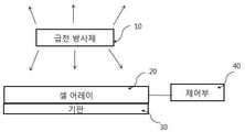
도 1은 본 발명의 일 실시예에 따른 반사형 셀 어레이 안테나의 구조를 도시한 개념도이다.1 is a conceptual diagram illustrating a structure of a reflection type cell array antenna according to an embodiment of the present invention.
도 1을 참조하면, 본 발명의 일 실시예에 따른 반사형 셀 어레이 안테나는 급전 방사체(10), 셀 어레이(20), 기판(30) 및 제어부(40)를 포함한다.Referring to FIG. 1, a reflection type cell array antenna according to an embodiment of the present invention includes a
급전 방사체(10)는 급전 신호를 제공받아 RF 신호를 외부에 방사하거나 외부로부터 RF 신호를 수신하는 기능을 한다. 본 발명의 일 실시예에 따르면, 급전 방사체(10)는 전 방향성의 방사 패턴을 가지는 방사체가 사용될 수 있으나 이에 한정되는 것은 아니다.The
일례로, 다이폴 방사체, 모노폴 방사체와 같은 방사체가 급전 방사체(10)로 사용될 수 있을 것이다.For example, a radiator such as a dipole radiator or a monopole radiator may be used as the
급전 방사체(10)가 방사하는 신호의 일부는 셀 어레이(20)로 향하게 되고, 셀 어레이(20)로 향한 신호는 셀 어레이(20)에서 반사된다. 따라서, 급전 방사체(10)에서 방사되는 신호는 직접 방사되는 직접파와 셀 어레이(20)로부터 반사되는 파로 구분될 수 있다.A part of the signal radiated by the
급전 방사체(10)의 하부에는 셀 어레이(20)가 구비되며, 셀 어레이(20)는 기판(30)상에 형성된다. 셀 어레이(20)는 금속 재질의 다수의 단위 셀이 배열된 구조를 의미한다. 셀 어레이(20)를 구성하는 단위 셀들의 배열 구조는 다양하게 설정될 수 있으며, 배열 구조는 요구되는 방사 특성에 기초하여 정해질 수 있을 것이다. 단위 셀은 접지 및 급전과 연결되지 않는 무급전 상태일 수 있다.A
일례로, 배열 구조는 다수의 단위 셀이 주기적으로 배열된 구조일 수도 있으며, 다수의 단위 셀이 비주기적으로 배열된 구조일 수도 있을 것이다. 단위 셀의 배열 구조뿐만 아니라 단위 셀의 형태 역시 전체적인 방사 패턴에 영향을 미칠 수 있는데, 단위 셀의 형태는 별도의 도면을 참조하여 상세히 설명한다.For example, the array structure may be a structure in which a plurality of unit cells are periodically arranged, or a structure in which a plurality of unit cells are arranged in an aperiodic manner. Not only the arrangement structure of the unit cells but also the shape of the unit cells may affect the overall radiation pattern. The shape of the unit cells will be described in detail with reference to a separate drawing.
셀 어레이(20)는 기판(30)상에 형성되며, 기판(30)은 유전체 재질로 이루어진다.The
한편, 도시되어 있지는 않으나, 기판(30)의 하부에는 접지와 전기적으로 연결되는 접지면이 결합될 수 있다.Although not shown, a ground plane electrically connected to the ground may be coupled to a lower portion of the
급전 방사체(10)와 셀 어레이(20)는 임의의 거리만큼 이격되며, 종래 기술에서 설명한 바와 같이 일반적인 반사형 셀 어레이 안테나는 동작 주파수의 파장 길이의 약 10배 정도의 거리만큼 이격된다.The
이와 같이 파장 길이의 10배 정도로 급전 방사체(10)를 이격시키는 것은 셀 어레이(20)에서의 반사되는 파에 대해 원거리장(Far Field)에 기초하여 해석하기 때문이다.This is because separating the
근거리장(Near Field)에 기초하여 반사되는 파를 해석하게 될 경우 그 해석이 매우 복잡해지며 이로 인해 근거리장에 기초한 셀 어레이의 구조를 설계하기 매우 어려운 문제점이 있었다.
When the reflected wave is analyzed based on the near field, the analysis becomes very complicated, and it is very difficult to design the structure of the cell array based on the near field.
따라서, 종래의 반사형 셀 어레이 안테나는 급전 방사체(10)와 셀 어레이(20) 사이의 이격 거리로 인해 큰 사이즈를 가질 수 밖에 없었으며, 파장 길이가 큰 저주파 대역에서는 사실상 사용되기 어려운 문제점이 있었다.Therefore, the conventional reflection type cell array antenna has a large size due to the separation distance between the
본 발명에서는 근거리장에 의해 셀 어레이 구조를 해석하지 않으면서 급전 방사체(10)와 셀 어레이(20)의 거리를 줄일 수 있는 구조의 반사형 셀 어레이를 제안한다.The present invention proposes a reflection type cell array having a structure capable of reducing the distance between the
본 발명의 일 실시예에 따르면, 급전 방사체(10)와 셀 어레이(20) 사이의 이격 거리는 1.5λ 이하의 거리로 설정된다. 여기서, λ는 안테나의 동작 주파수에 상응하는 파장 길이를 의미한다. 본 발명에서는 이와 같이 셀 어레이(20)와 급전 방사체(10) 사이의 거리를 현저히 줄인 상태에서 적절한 이득이 나올 수 있는 셀 어레이(20) 및 제어부(40)를 제안한다.According to an embodiment of the present invention, the distance between the
본 발명의 바람직한 실시예에 따르면, 제어부(40)는 셀 어레이에서 반사되는 반사파의 반사 위상을 조절하기 위한 제어 동작을 수행한다. 제어부(40)에서 이루어지는 상세한 제어 동작은 별도의 도면을 참조하여 상세히 설명한다.According to a preferred embodiment of the present invention, the
도 2 및 도 3은 본 발명의 일 실시예에 따른 반사형 셀 어레이 안테나의 급전 방사체의 구조를 도시한 도면으로서, 도 2는 기판을 중심으로 급전 방사체의 상부면을 도시한 도면이고, 도 3은 기판을 중심으로 급전 방사체의 하부면을 도시한 도면이다.2 and 3 are views showing a structure of a feeder of a reflection type cell array antenna according to an embodiment of the present invention. Fig. 2 is a view showing an upper surface of a feeder with a substrate as a center, Is a view showing a lower surface of a feed radiator about a substrate.
도 2 및 도 3을 참조하면, 기판(200)의 상부에는 RF 신호의 방사를 수행하는 방사체(210)가 형성되며, 기판(200)의 하부에는 방사체(210)에 급전 신호를 제공하기 위한 급전 구조체(220)가 형성된다.2 and 3, a
도 2를 참조하면, 방사체(210)는 제1 엘리먼트(211) 및 제2 엘리먼트(212)를 포함하는 다이폴 방사체이다. 물론, 다이폴 방사체는 본 발명의 급전 방사체의 일례에 불과하며 다양한 종류의 방사체가 사용될 수 있을 것이다. 다이폴 방사체는 전방향성의 방사 패턴을 가진다.Referring to FIG. 2, the
다이폴 방사체의 제1 엘리먼트(211)는 급전 신호를 제공받으며, 제2 엘리먼트(212)는 접지와 전기적으로 연결된다. 제1 엘리먼트(211)는 급전 구조체(220)와 연결되어 급전 신호를 제공받는다.The
일례로, 제1 엘리먼트(211)는 급전 구조체(220)와 비아홀을 통해 연결되어 급전 신호를 제공받을 수 있다.For example, the
도 4는 본 발명의 일 실시예에 따른 반사형 셀 어레이 안테나의 동작 구조를 도시한 도면이다.4 is a diagram illustrating an operation structure of a reflection type cell array antenna according to an embodiment of the present invention.
도 4를 참조하면, 급전 방사체(10)로부터 방사되는 방사 신호는 외부로 직접 방사되는 직접파(131)를 포함한다. 또한, 방사 신호는 셀 어레이(20)로부터 반사되는 반사파(130)를 포함한다.Referring to FIG. 4, the radiation signal emitted from the
결국, 반사형 셀 어레이 안테나는 직접파(131)와 반사파(130)가 함께 방사 신호를 구성하게 되며, 직접파(131)와 반사파(130)가 어떻게 중첩되는지에 따라 전체적인 방사 패턴이 결정되는 것이다.As a result, in the reflection type cell array antenna, the
반사파(130)의 빔 방향 및 위상은 셀 어레이(20)의 구조에 따라 달라지며, 본 발명에서는 제어부(40)를 통해 반사파(130)이 반사 위상을 조절하여 급전 방사체(10)와 셀 어레이(20)이 간격이 근접할 경우에도 적절한 이득이 확보될 수 있는 반사형 셀 어레이 안테나를 제공한다.The direction and phase of the beam of the reflected
도 5는 기존의 반사형 셀 어레이 안테나에서의 해석 방법을 설명하기 위한 도면이다.5 is a view for explaining an analysis method in a conventional reflection type cell array antenna.
도 5를 참조하면, 급전 방사체(10)와 셀 어레이를 구성하는 단위 셀간의 관계는 원거리장에 기초하여 해석되며 안테나의 가역적 특성을 이용하여 TE 모드 또는 TM 모드의 원거리 영역에서 입사파를 해석하게 된다.Referring to FIG. 5, the relationship between the
이와 같은 해석 방식에 의해 셀 어레이가 설계되기 때문에 기존의 반사형 셀 어레이 안테나에서의 셀 어레이는 대부분 주기적 구조를 가지고 셀 어레이의 형태 역시 균일한 구조를 가지는 것이 일반적이었다.Since the cell array is designed by such an analysis method, the cell array in the conventional reflective cell array antenna generally has a periodic structure and the cell array has a uniform structure.
그러나, 주기적이고 균일한 구조의 셀 어레이로는 급전 방사체(10)가 한 파장 이내로 인접하여 위치할 경우 적절한 이득의 방사 패턴을 확보할 수 없는 문제점이 있었다.However, there is a problem in that a radiation pattern of an appropriate gain can not be secured in a cell array having a periodic and uniform structure when the
도 6은 본 발명의 일 실시예에 따른 반사형 셀 어레이 안테나에서 셀 어레이의 구조를 도시한 도면이다.6 is a view illustrating a structure of a cell array in a reflection type cell array antenna according to an embodiment of the present invention.
도 6을 참조하면, 다수의 단위 셀이 기판(30)상에 배열되며, 단위 셀(600, 601, 602)은 다양한 형태를 가지고 있다. 단위 셀(600, 601, 602)이 다양한 형태를 가지므로 단위 셀의 배열 구조는 비주기적이다.Referring to FIG. 6, a plurality of unit cells are arranged on the
급전 방사체(10)는 기판(30)상에 배열된 다양한 형태의 단위 셀(600, 601, 602)에 RF 신호를 방사한다. 이때, 급전 방사체(10)는 원하는 빔 방향에 상응하는 각도로 신호를 방사하며, 앞서 설명한 바와 같이 직접 방사되는 직접파와 단위 셀들로부터 반사되는 반사파가 함께 방사 신호를 형성하게 된다.The
급전 방사체(10)가 소정 각도로 신호를 방사하기 때문에 방사 신호는 소정 각도를 가진 파면을 형성하게 된다.Since the
도 6에서, 단위 셀들이 다양한 형태를 가지는 것은 원하는 반사 위상 특성을 확보하기 위해서이다. 그러나, 단위 셀의 형태 변화만으로 원하는 반사 위상 특성을 확보할 수 없는 경우가 있으며 또한 가공 오차에 의해 의도한 반사 위상 특성이 확보되지 않을 수도 있다.In FIG. 6, the unit cells have various shapes in order to secure desired reflection phase characteristics. However, the desired reflection phase characteristic can not be secured only by the change in the shape of the unit cell, and the intended reflection phase characteristic may not be secured due to the processing error.
본 발명의 바람직한 실시예에 따르면, 단위 셀에 가변 리액티브 소자를 결합하고, 제어부(40)에서 가변 리액티브 소자의 캐패시턴스를 변화시켜 각 단위 셀에서의 반사 위상 특성을 제어한다. 여기서, 가변 리액티브 소자는 소자의 캐패시턴스 또는 인덕턴스를 가변시킬 수 있는 소자를 의미한다.According to a preferred embodiment of the present invention, a variable reactive element is coupled to a unit cell, and the
도 7은 본 발명의 일 실시예에 따른 반사형 셀 어레이 안테나에서 가변 리액티브 소자의 결합 구조를 도시한 일례이다.7 is an example showing a coupling structure of a variable active element in a reflection type cell array antenna according to an embodiment of the present invention.
도 7을 참조하면, 가변 리액티브 소자(700)가 두개의 특정 단위셀들을 서로 연결하도록 결합된다. 즉, 단위셀들과 가변 리액티브 소자(700)가 직렬로 결합되는 구조이다.Referring to FIG. 7, a variable
여기서, 가변 리액티브 소자(700)는 버랙터 다이오드, 가변 칩 캐패시터, 가변 칩 인덕터를 포함할 수 있다.Here, the variable
일례로, 버택터 다이오드가 가변 리액티브 소자로 사용될 경우, 제어부(40)는 버랙터 다이오드로 인가되는 전압을 조절하여 버랙터 다이오드의 캐패시턴스를 조절할 수 있을 것이다.For example, when the bucker diode is used as a variable reactive element, the
도 7과 같이 제어가 이루어질 때 단위셀들 중 적어도 일부는 기판(30) 하부에 형성되는 접지면과 전기적으로 연결될 수 있다.7, at least a part of the unit cells may be electrically connected to the ground plane formed under the
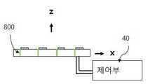
도 8은 본 발명의 다른 실시예에 따른 반사형 셀 어레이 안테나에서 가변 리액티브 소자의 결합 구조를 도시한 일례이다.8 is an example showing a coupling structure of a variable active element in a reflection type cell array antenna according to another embodiment of the present invention.
도 8을 참조하면, 가변 리액티브 소자(800)가 각 단위 셀마다 연결되는 구조를 가진다. 가변 리액티브 소자(800)의 일단은 단위 셀과 연결되고 타단은 접지면과 연결되는 구조를 가질 수 있다. 즉, 도 8에 도시된 예에서 가변 리액티브 소자(800)는 병렬로 연결되는 구조를 가진다. 이 경우 단위셀의 적어도 일부가 접지면과 연결될 수도 있을 것이다.Referring to FIG. 8, a variable
도 7 및 도 8에 도시된 바와 같이, 가변 리액티브 소자는 단위셀에 직렬 또는 병렬로 연결될 수 있으며, 제어부(40)는 가변 리액티브 소자의 캐패시턴스 또는 인덕턴스를 조절하여 궁극적으로 반사 위상을 조절한다.7 and 8, the variable active elements may be connected in series or in parallel to the unit cells, and the
이하에서는 급전 방사체가 한 파장의 거리 이내로 셀 어레이에 근접하더라도 적절한 이득을 확보할 수 있는 셀 어레이에서의 반사 위상 조절 방법에 대해 설명한다.Hereinafter, a method of adjusting the reflection phase in a cell array capable of ensuring an appropriate gain even if the feed emitter is close to the cell array within a distance of one wavelength will be described.
도 9는 본 발명의 일 실시예에 따른 반사 위상 조절 방법을 설명하기 위한 개념도이다.9 is a conceptual diagram for explaining a reflection phase adjustment method according to an embodiment of the present invention.
도 9를 참조하면, 급전 방사체(10)는 소정의 방향을 가진 직접파(d)를 방사한다. 또한, 급전 방사체(10)는 셀 어레이를 향해서도 RF 신호를 방사하며 셀 어레이를 통해 반사되는 반사파(rm1, rm2, rmn, rmN)가 형성된다.Referring to Fig. 9, the
본 발명은 급전 방사체(10)로부터 방사되는 직접파(d)와 셀 어레이의 단위셀로부터 반사되는 반사파(rm1, rm2, rmn, rmN)가 동일 위상을 가져 직접파와 반사파간 서로 보강 간섭이 이루어지도록 각 단위셀의 반사 위상을 조절한다.The invention feed the reflected wave reflected from the direct wave (d) the unit cells of the cell array to be emitted from the emitter(10) (r m1, r m2, r mn, r mN) the reinforcing each other brought between a direct wave and reflected wave of the same phase The reflection phase of each unit cell is adjusted so that the interference is generated.
직접파(d) 및 반사파(rm1, rm2, rmn, rmN)로 인해 특정 파면(900)이 정의될 수 있으며, 바람직하게는 파면(900)에서 직접파(d)와 반사파(rm1, rm2, rmn, rmN)가 동일 위상을 가져 보강 간섭이 이루어지도록 반사 위상이 조절된다.Direct wave (d) and the reflected wave (rm1, rm2, rmn, rmN) due to which a
급전 방사체로부터 방사되어 셀 어레이에서 (m,n)에 위치한 단위셀에 도달할 때까지의 위상 지연

위 수학식 2에서 rmn은 (m,n)에 위치한 단위셀에서 파면까지의 거리를 의미한다.In Equation (2), rmn means the distance from the unit cell located at (m, n) to the wavefront.
도 9를 참조하면, y 방향으로 서로 인접한 단위 셀(예를 들어, n, n-1 번째 단위 셀)간의 거리 차이는

셀 어레이에서 (m,n)에 위치한 단위셀의 반사계수의 위상을

위 수학식 4에서,
정의된 특정 파면에서 직접파와 단위셀들로부터의 반사파가 보강 간섭이 이루어지도록 하는 관계는 다음의 수학식 5와 같다.The relationship that the direct wave and the reflected wave from the unit cells in the defined specific wavefront cause the constructive interference to occur is expressed by Equation (5).

정의된 특정 파면에서 반사파들과 직접파가 보강 간섭이 이루어지기 위한 각 단위셀에서의 반사 위상은 다음의 수학식 5와 같이 정의될 수 있다.The reflection phase in each unit cell for the constructive interference of the direct waves with the reflected waves in the defined specific wavefront can be defined as Equation (5).

본 발명의 바람직한 실시예에 따르면, 각 단위셀의 반사 위상을 다음의 수학식 5와 같이 조절하여 급전 방사체와 셀 어레이간의 거리가 한파장 거리 이내로 줄어들더라도 양호한 이득을 제공할 수 있게 된다.According to a preferred embodiment of the present invention, the reflection phase of each unit cell can be adjusted as shown in Equation (5) to provide a good gain even if the distance between the feed emitter and the cell array is reduced to within a one-wave distance.
앞서 설명한 바와 같이 반사 위상의 조절은 단위셀의 사이즈 및 형태를 조절하거나 단위셀과 연결된 가변 리액티브 소자의 캐패시턴스 또는 인덕턴스를 조절함으로써 수행될 수 있다.As described above, the adjustment of the reflection phase can be performed by adjusting the size and shape of the unit cell or adjusting the capacitance or inductance of the variable reactive element connected to the unit cell.
위에서 설명한 반사 위상 조절은 셀 어레이를 이루는 단위셀들의 형태 및 사이즈를 변경함으로써 이루어질 수도 있을 것이다. 예를 들어 도 6에 도시된 셀 어레이 구조에서 셀 어레이를 구성하는 각 단위셀의 형태 및 사이즈를 변경하여 수학식 5와 같이 반사 위상이 조절되도록 안테나가 설계될 수도 있을 것이다.The reflection phase adjustment described above may be performed by changing the shape and size of the unit cells constituting the cell array. For example, in the cell array structure shown in FIG. 6, an antenna may be designed so that the reflection phase is adjusted as shown in Equation (5) by changing the shape and size of each unit cell constituting the cell array.
전술한 본 발명의 설명은 예시를 위한 것이며, 본 발명이 속하는 기술분야의 통상의 지식을 가진 자는 본 발명의 기술적 사상이나 필수적인 특징을 변경하지 않고서 다른 구체적인 형태로 쉽게 변형이 가능하다는 것을 이해할 수 있을 것이다.It will be understood by those skilled in the art that the foregoing description of the present invention is for illustrative purposes only and that those of ordinary skill in the art can readily understand that various changes and modifications may be made without departing from the spirit or essential characteristics of the present invention. will be.
그러므로 이상에서 기술한 실시예들은 모든 면에서 예시적인 것이며 한정적이 아닌 것으로 이해해야만 한다.It is therefore to be understood that the above-described embodiments are illustrative in all aspects and not restrictive.
예를 들어, 단일형으로 설명되어 있는 각 구성 요소는 분산되어 실시될 수도 있으며, 마찬가지로 분산된 것으로 설명되어 있는 구성 요소들도 결합된 형태로 실시될 수 있다.For example, each component described as a single entity may be distributed and implemented, and components described as being distributed may also be implemented in a combined form.
본 발명의 범위는 후술하는 특허청구범위에 의하여 나타내어지며, 특허청구범위의 의미 및 범위 그리고 그 균등 개념으로부터 도출되는 모든 변경 또는 변형된 형태가 본 발명의 범위에 포함되는 것으로 해석되어야 한다.
The scope of the present invention is defined by the appended claims, and all changes or modifications derived from the meaning and scope of the claims and their equivalents should be construed as being included within the scope of the present invention.
Claims (13)
Translated fromKorean상기 급전 방사체와 임의의 거리로 이격되며 다수의 단위셀이 배열되는 셀 어레이를 포함하되,
상기 단위셀 중 적어도 일부에는 가변 리액티브 소자가 결합되며 상기 가변 리액티브 소자의 캐패시턴스 또는 인덕턴스를 조절하는 제어부를 더 포함하되,
상기 제어부는 상기 급전 방사체로부터 직접 방사되는 직접파와 상기 다수의 단위셀을 통해 반사되는 반사파들이 미리 정의된 특정 파면에서 보강 간섭이 이루어지도록 상기 다수의 단위셀의 반사 위상을 조절하며,
상기 셀 어레이의 (m,n)에 위치한 단위셀들의 반사 위상은 다음의 수학식과 같이 설정되는 것을 특징으로 하는 반사형 셀 어레이 안테나.

위 수학식에서, f는 주파수, c는 전자파의 속도, lmn은 급전 방사체로부터 (m,n)에 위치한 단위셀까지의 거리, rmn은 (m,n)에 위치한 단위셀에서 상기 미리 정의된 특정 파면까지의 거리, d는 급전 방사체로부터 상기 미리 정의된 특정 파면까지의 거리, q는 임의의 정수를 의미하고, m,n은 셀 어레이에서 단위 셀들의 위치에 대한 인덱스를 의미하고,


A feed emitter feeding and radiating an RF signal;
And a cell array spaced apart from the feeder by a predetermined distance and having a plurality of unit cells arranged therein,
And a control unit coupled to at least a part of the unit cells to adjust a capacitance or an inductance of the variable reactive device,
Wherein the control unit adjusts the reflection phases of the plurality of unit cells so that the direct wave radiated directly from the feeder and the reflected waves reflected through the plurality of unit cells are subjected to constructive interference at a predefined specific wavefront,
Wherein the reflection phase of the unit cells located at (m, n) of the cell array is set according to the following equation.
Wherem is the distance from the feed emitter to the unit cell located at (m, n), and rmn is the distance from the predefined unit cell at (m, n) D is the distance from the feed emitter to the predetermined wave front, q is an arbitrary integer, m and n are the indices of the positions of the unit cells in the cell array,
상기 급전 방사체와 상기 셀 어레이 사이의 거리는 1.5λ 이하로 설정되는 것을 특징으로 하는 반사형 셀 어레이 안테나.
The method according to claim 1,
And a distance between the feed radiator and the cell array is set to be equal to or smaller than 1.5?.
상기 가변 리액티브 소자는 버랙터 다이오드를 포함하며, 상기 제어부는 상기 버랙터 다이오드로 인가되는 전압을 조절하는 것을 특징으로 하는 반사형 셀 어레이 안테나.
The method according to claim 1,
Wherein the variable active element includes a varactor diode, and the control unit adjusts a voltage applied to the varactor diode.
상기 가변 리액티브 소자는 칩 캐패시터를 포함하는 것을 특징으로 하는 반사형 셀 어레이 안테나.
The method according to claim 1,
Wherein the variable active element comprises a chip capacitor.
상기 급전 방사체와 임의의 거리로 이격되며 다수의 단위셀이 배열되는 셀 어레이를 포함하되,
상기 급전 방사체와 상기 셀 어레이 사이의 거리는 1.5λ 이하로 설정되며, 상기 다수의 단위셀 중 적어도 하나의 반사 위상을 조절하는 수단을 더 포함하며,
상기 반사 위상을 조절하는 수단은,
상기 다수의 단위셀 중 적어도 일부에 결합되는 가변 리액티브 소자 및 상기 가변 리액티브 소자의 캐패시턴스 또는 인덕턴스를 조절하는 제어부를 포함하며,
상기 제어부는 상기 급전 방사체로부터 직접 방사되는 직접파와 상기 다수의 단위셀을 통해 반사되는 반사파들이 미리 정의된 특정 파면에서 보강 간섭이 이루어지도록 상기 다수의 단위셀의 반사 위상을 조절하고,
상기 셀 어레이의 (m,n)에 위치한 단위셀들의 반사 위상은 다음의 수학식과 같이 설정되는 것을 특징으로 하는 반사형 셀 어레이 안테나.

위 수학식에서, f는 주파수, c는 전자파의 속도, lmn은 급전 방사체 로부터 (m,n)에 위치한 단위셀까지의 거리, rmn은 (m,n)에 위치한 단위셀에서 상기 미리 정의 된 특정 파면까지의 거리, d는 급전 방사체로부터 상기 미리 정의된 특정 파면까지의 거리, q는 임의의 정수를 의미하고, m,n은 셀 어레이에서 단위 셀들의 위치에 대한 인덱스를 의미하고,


A feed emitter feeding and radiating an RF signal;
And a cell array spaced apart from the feeder by a predetermined distance and having a plurality of unit cells arranged therein,
A distance between the feeder and the cell array is set to be equal to or less than 1.5 ?, and means for adjusting the reflection phase of at least one of the plurality of unit cells,
Wherein the means for adjusting the reflection phase comprises:
A variable reactive element coupled to at least a portion of the plurality of unit cells, and a controller for adjusting a capacitance or an inductance of the variable reactive element,
Wherein the control unit adjusts the reflection phases of the plurality of unit cells so that the direct wave radiated directly from the feeder and the reflected waves reflected through the plurality of unit cells are subjected to constructive interference at a predefined specific wavefront,
Wherein the reflection phase of the unit cells located at (m, n) of the cell array is set according to the following equation.
Wherem is the distance from the feed emitter to the unit cell located at (m, n), and rmn is the distance from the predefined unit cell at (m, n) D is the distance from the feed emitter to the predetermined wave front, q is an arbitrary integer, m and n are the indices of the positions of the unit cells in the cell array,
상기 가변 리액티브 소자는 버랙터 다이오드를 포함하며, 상기 제어부는 상기 버랙터 다이오드로 인가되는 전압을 조절하는 것을 특징으로 하는 반사형 셀 어레이 안테나.
8. The method of claim 7,
Wherein the variable active element includes a varactor diode, and the control unit adjusts a voltage applied to the varactor diode.
상기 급전 방사체와 임의의 거리로 이격되며 다수의 단위셀이 배열되는 셀 어레이를 포함하되,
상기 셀 어레이의 단위셀들 각각의 사이즈 및 형태는 상기 급전 방사체로부터 직접 방사되는 직접파와 상기 다수의 단위셀을 통해 반사되는 반사파들이 미리 정의된 특정 파면에서 보강 간섭이 이루어지는 반사 위상을 가지도록 설정되며,
상기 셀 어레이의 (m,n)에 위치한 단위셀들의 반사 위상은 다음의 수학식과 같이 설정되는 것을 특징으로 하는 반사형 셀 어레이 안테나.

위 수학식에서, f는 주파수, c는 전자파의 속도, lmn은 급전 방사체로부터 (m,n)에 위치한 단위셀까지의 거리, rmn은 (m,n)에 위치한 단위셀에서 상기 미리 정의된 특정 파면까지의 거리, d는 급전 방사체로부터 상기 미리 정의된 특정 파면까지의 거리, q는 임의의 정수를 의미하고, m,n은 셀 어레이에서 단위 셀들의 위치에 대한 인덱스를 의미하고,


A feed emitter feeding and radiating an RF signal;
And a cell array spaced apart from the feeder by a predetermined distance and having a plurality of unit cells arranged therein,
The sizes and shapes of the unit cells of the cell array are set so that direct waves directly radiated from the feeder emitters and reflected waves reflected through the plurality of unit cells have a reflection phase in which constructive interference occurs at a predefined specific wavefront ,
Wherein the reflection phase of the unit cells located at (m, n) of the cell array is set according to the following equation.
Wherem is the distance from the feed emitter to the unit cell located at (m, n), and rmn is the distance from the predefined unit cell at (m, n) D is the distance from the feed emitter to the predetermined wave front, q is an arbitrary integer, m and n are the indices of the positions of the unit cells in the cell array,
Priority Applications (2)
| Application Number | Priority Date | Filing Date | Title |
|---|---|---|---|
| KR1020150129199AKR101751123B1 (en) | 2015-09-11 | 2015-09-11 | Reflect Type Cell Array Antenna with Small Size |
| PCT/KR2016/010267WO2017043946A1 (en) | 2015-09-11 | 2016-09-12 | Reflective cell-array antenna having miniaturised structure |
Applications Claiming Priority (1)
| Application Number | Priority Date | Filing Date | Title |
|---|---|---|---|
| KR1020150129199AKR101751123B1 (en) | 2015-09-11 | 2015-09-11 | Reflect Type Cell Array Antenna with Small Size |
Publications (2)
| Publication Number | Publication Date |
|---|---|
| KR20170031527A KR20170031527A (en) | 2017-03-21 |
| KR101751123B1true KR101751123B1 (en) | 2017-07-11 |
Family
ID=58240294
Family Applications (1)
| Application Number | Title | Priority Date | Filing Date |
|---|---|---|---|
| KR1020150129199AExpired - Fee RelatedKR101751123B1 (en) | 2015-09-11 | 2015-09-11 | Reflect Type Cell Array Antenna with Small Size |
Country Status (2)
| Country | Link |
|---|---|
| KR (1) | KR101751123B1 (en) |
| WO (1) | WO2017043946A1 (en) |
Families Citing this family (3)
| Publication number | Priority date | Publication date | Assignee | Title |
|---|---|---|---|---|
| KR102207836B1 (en)* | 2019-10-28 | 2021-01-25 | 세종대학교산학협력단 | Reflect cell, beam steering antenna and wireless communication device with the same |
| KR102405863B1 (en)* | 2021-04-26 | 2022-06-03 | 세종대학교산학협력단 | Multiple reflection antenn, communication device including same, and radio wave analysis method thereof |
| KR102678612B1 (en) | 2022-10-27 | 2024-06-26 | 국방과학연구소 | Method and device for modeling of transmit-array antenna |
Family Cites Families (5)
| Publication number | Priority date | Publication date | Assignee | Title |
|---|---|---|---|---|
| US6081235A (en)* | 1998-04-30 | 2000-06-27 | The United States Of America As Represented By The Administrator Of The National Aeronautics And Space Administration | High resolution scanning reflectarray antenna |
| US7710326B2 (en)* | 2006-10-20 | 2010-05-04 | Agilent Technologies, Inc. | Antenna clusters for active device reduction in phased arrays with restricted scan |
| US7791552B1 (en)* | 2007-10-12 | 2010-09-07 | The United States Of America As Represented By The Administrator Of The National Aeronautics And Space Administration | Cellular reflectarray antenna and method of making same |
| US7868829B1 (en)* | 2008-03-21 | 2011-01-11 | Hrl Laboratories, Llc | Reflectarray |
| KR20130098098A (en)* | 2012-02-27 | 2013-09-04 | 한국전자통신연구원 | High-gain wideband antenna apparatus |
- 2015
- 2015-09-11KRKR1020150129199Apatent/KR101751123B1/ennot_activeExpired - Fee Related
- 2016
- 2016-09-12WOPCT/KR2016/010267patent/WO2017043946A1/ennot_activeCeased
Also Published As
| Publication number | Publication date |
|---|---|
| KR20170031527A (en) | 2017-03-21 |
| WO2017043946A1 (en) | 2017-03-16 |
Similar Documents
| Publication | Publication Date | Title |
|---|---|---|
| Bouslama et al. | Beam-switching antenna with a new reconfigurable frequency selective surface | |
| EP3381084B1 (en) | Phased array antennas having decoupling units | |
| KR101307113B1 (en) | Circularly polarized loop reflector antenna and associated methods | |
| Chen et al. | Low-profile wideband reflectarray by novel elements with linear phase response | |
| US9413073B2 (en) | Augmented E-plane taper techniques in variable inclination continuous transverse (VICTS) antennas | |
| KR20130098098A (en) | High-gain wideband antenna apparatus | |
| US8970441B2 (en) | Antenna apparatus | |
| CN107210522A (en) | There is the antenna for base station of dummy elements between subarray | |
| JP6397563B2 (en) | Leaky wave antenna | |
| KR101751123B1 (en) | Reflect Type Cell Array Antenna with Small Size | |
| US20190027831A1 (en) | Parasitic antenna arrays incorporating fractal metamaterials | |
| JP5054174B2 (en) | antenna | |
| US9337533B2 (en) | Ground plane meandering in Z direction for spiral antenna | |
| US8462064B2 (en) | Multiband dismount antenna | |
| KR200404222Y1 (en) | A side-fed patch antenna with reduced size | |
| KR102299534B1 (en) | A Small RFID Antenna System with Plenar Reflectarray for High Antenna Gain | |
| Wongsin et al. | High gain multiband circular loop antenna with ring resonators reflectors by using FSS technique | |
| Singh et al. | Performance comparison of phase shifting surface lens antenna with other lens antennas | |
| JP2001185944A (en) | Antenna device | |
| JP2001189620A (en) | Array antenna | |
| RU115569U1 (en) | ULTRA-BAND RADIATING ELEMENT WITH COAXIAL INPUT AND ANTENNA ARRAY CONTAINING SUCH RADIATING ELEMENT | |
| US20170179604A1 (en) | Wide band antenna | |
| Degiorgi et al. | A sectorial Fabry-Perot antenna for radar application | |
| Afzal et al. | Integration of sparse array feed and phase correction to design high gain resonant cavity antennas | |
| Zuo et al. | A Compact High-Gain Multi-Beam Lens Antenna Utilizing Quasi-Conformal Transformation Optics |
Legal Events
| Date | Code | Title | Description |
|---|---|---|---|
| A201 | Request for examination | ||
| PA0109 | Patent application | St.27 status event code:A-0-1-A10-A12-nap-PA0109 | |
| PA0201 | Request for examination | St.27 status event code:A-1-2-D10-D11-exm-PA0201 | |
| P11-X000 | Amendment of application requested | St.27 status event code:A-2-2-P10-P11-nap-X000 | |
| P13-X000 | Application amended | St.27 status event code:A-2-2-P10-P13-nap-X000 | |
| E902 | Notification of reason for refusal | ||
| PE0902 | Notice of grounds for rejection | St.27 status event code:A-1-2-D10-D21-exm-PE0902 | |
| AMND | Amendment | ||
| E13-X000 | Pre-grant limitation requested | St.27 status event code:A-2-3-E10-E13-lim-X000 | |
| P11-X000 | Amendment of application requested | St.27 status event code:A-2-2-P10-P11-nap-X000 | |
| P13-X000 | Application amended | St.27 status event code:A-2-2-P10-P13-nap-X000 | |
| PG1501 | Laying open of application | St.27 status event code:A-1-1-Q10-Q12-nap-PG1501 | |
| E601 | Decision to refuse application | ||
| PE0601 | Decision on rejection of patent | St.27 status event code:N-2-6-B10-B15-exm-PE0601 | |
| AMND | Amendment | ||
| E13-X000 | Pre-grant limitation requested | St.27 status event code:A-2-3-E10-E13-lim-X000 | |
| P11-X000 | Amendment of application requested | St.27 status event code:A-2-2-P10-P11-nap-X000 | |
| P13-X000 | Application amended | St.27 status event code:A-2-2-P10-P13-nap-X000 | |
| PX0901 | Re-examination | St.27 status event code:A-2-3-E10-E12-rex-PX0901 | |
| GRNT | Written decision to grant | ||
| PR0701 | Registration of establishment | St.27 status event code:A-2-4-F10-F11-exm-PR0701 | |
| PR1002 | Payment of registration fee | St.27 status event code:A-2-2-U10-U11-oth-PR1002 Fee payment year number:1 | |
| PX0701 | Decision of registration after re-examination | St.27 status event code:A-3-4-F10-F13-rex-PX0701 | |
| X701 | Decision to grant (after re-examination) | ||
| PG1601 | Publication of registration | St.27 status event code:A-4-4-Q10-Q13-nap-PG1601 | |
| P22-X000 | Classification modified | St.27 status event code:A-4-4-P10-P22-nap-X000 | |
| PR1001 | Payment of annual fee | St.27 status event code:A-4-4-U10-U11-oth-PR1001 Fee payment year number:4 | |
| PN2301 | Change of applicant | St.27 status event code:A-5-5-R10-R13-asn-PN2301 St.27 status event code:A-5-5-R10-R11-asn-PN2301 | |
| PN2301 | Change of applicant | St.27 status event code:A-5-5-R10-R13-asn-PN2301 St.27 status event code:A-5-5-R10-R11-asn-PN2301 | |
| PR1001 | Payment of annual fee | St.27 status event code:A-4-4-U10-U11-oth-PR1001 Fee payment year number:5 | |
| PR1001 | Payment of annual fee | St.27 status event code:A-4-4-U10-U11-oth-PR1001 Fee payment year number:6 | |
| PC1903 | Unpaid annual fee | St.27 status event code:A-4-4-U10-U13-oth-PC1903 Not in force date:20230621 Payment event data comment text:Termination Category : DEFAULT_OF_REGISTRATION_FEE | |
| PC1903 | Unpaid annual fee | St.27 status event code:N-4-6-H10-H13-oth-PC1903 Ip right cessation event data comment text:Termination Category : DEFAULT_OF_REGISTRATION_FEE Not in force date:20230621 |