KR101749970B1 - End-effector of Surgical linear stapler - Google Patents
End-effector of Surgical linear staplerDownload PDFInfo
- Publication number
- KR101749970B1 KR101749970B1KR1020160087182AKR20160087182AKR101749970B1KR 101749970 B1KR101749970 B1KR 101749970B1KR 1020160087182 AKR1020160087182 AKR 1020160087182AKR 20160087182 AKR20160087182 AKR 20160087182AKR 101749970 B1KR101749970 B1KR 101749970B1
- Authority
- KR
- South Korea
- Prior art keywords
- unit
- staple
- stabilizer
- anvil
- guide slit
- Prior art date
- Legal status (The legal status is an assumption and is not a legal conclusion. Google has not performed a legal analysis and makes no representation as to the accuracy of the status listed.)
- Active
Links
- 239000012636effectorSubstances0.000title1
- 239000003381stabilizerSubstances0.000claimsabstractdescription166
- 238000000034methodMethods0.000claimsabstractdescription24
- 230000001575pathological effectEffects0.000claimsabstractdescription7
- 238000007599dischargingMethods0.000claimsdescription47
- 238000003825pressingMethods0.000claimsdescription24
- 230000007423decreaseEffects0.000claimsdescription2
- 230000000087stabilizing effectEffects0.000claimsdescription2
- 210000000056organAnatomy0.000description9
- 238000001356surgical procedureMethods0.000description4
- 238000001574biopsyMethods0.000description3
- 206010028980NeoplasmDiseases0.000description2
- 201000011510cancerDiseases0.000description2
- 239000000463materialSubstances0.000description2
- 230000007170pathologyEffects0.000description2
- 230000003187abdominal effectEffects0.000description1
- 230000003872anastomosisEffects0.000description1
- 230000000694effectsEffects0.000description1
- 238000010562histological examinationMethods0.000description1
- 238000005286illuminationMethods0.000description1
- 238000002357laparoscopic surgeryMethods0.000description1
- 238000012986modificationMethods0.000description1
- 230000004048modificationEffects0.000description1
- 238000011084recoveryMethods0.000description1
- 230000037390scarringEffects0.000description1
- 238000004904shorteningMethods0.000description1
- 210000000115thoracic cavityAnatomy0.000description1
Images


Classifications
- A—HUMAN NECESSITIES
- A61—MEDICAL OR VETERINARY SCIENCE; HYGIENE
- A61B—DIAGNOSIS; SURGERY; IDENTIFICATION
- A61B17/00—Surgical instruments, devices or methods
- A61B17/068—Surgical staplers, e.g. containing multiple staples or clamps
- A61B17/072—Surgical staplers, e.g. containing multiple staples or clamps for applying a row of staples in a single action, e.g. the staples being applied simultaneously
- A61B17/07207—Surgical staplers, e.g. containing multiple staples or clamps for applying a row of staples in a single action, e.g. the staples being applied simultaneously the staples being applied sequentially
- A—HUMAN NECESSITIES
- A61—MEDICAL OR VETERINARY SCIENCE; HYGIENE
- A61B—DIAGNOSIS; SURGERY; IDENTIFICATION
- A61B17/00—Surgical instruments, devices or methods
- A61B17/068—Surgical staplers, e.g. containing multiple staples or clamps
- A—HUMAN NECESSITIES
- A61—MEDICAL OR VETERINARY SCIENCE; HYGIENE
- A61B—DIAGNOSIS; SURGERY; IDENTIFICATION
- A61B10/00—Instruments for taking body samples for diagnostic purposes; Other methods or instruments for diagnosis, e.g. for vaccination diagnosis, sex determination or ovulation-period determination; Throat striking implements
- A61B10/0096—Casings for storing test samples
- A—HUMAN NECESSITIES
- A61—MEDICAL OR VETERINARY SCIENCE; HYGIENE
- A61B—DIAGNOSIS; SURGERY; IDENTIFICATION
- A61B10/00—Instruments for taking body samples for diagnostic purposes; Other methods or instruments for diagnosis, e.g. for vaccination diagnosis, sex determination or ovulation-period determination; Throat striking implements
- A61B10/02—Instruments for taking cell samples or for biopsy
- A—HUMAN NECESSITIES
- A61—MEDICAL OR VETERINARY SCIENCE; HYGIENE
- A61B—DIAGNOSIS; SURGERY; IDENTIFICATION
- A61B17/00—Surgical instruments, devices or methods
- A61B17/11—Surgical instruments, devices or methods for performing anastomosis; Buttons for anastomosis
- A61B17/115—Staplers for performing anastomosis, e.g. in a single operation
- A—HUMAN NECESSITIES
- A61—MEDICAL OR VETERINARY SCIENCE; HYGIENE
- A61B—DIAGNOSIS; SURGERY; IDENTIFICATION
- A61B17/00—Surgical instruments, devices or methods
- A61B17/32—Surgical cutting instruments
- A61B17/3205—Excision instruments
- A61B17/32053—Punch like cutting instruments, e.g. using a cylindrical or oval knife
- A—HUMAN NECESSITIES
- A61—MEDICAL OR VETERINARY SCIENCE; HYGIENE
- A61B—DIAGNOSIS; SURGERY; IDENTIFICATION
- A61B17/00—Surgical instruments, devices or methods
- A61B17/068—Surgical staplers, e.g. containing multiple staples or clamps
- A61B17/072—Surgical staplers, e.g. containing multiple staples or clamps for applying a row of staples in a single action, e.g. the staples being applied simultaneously
- A61B2017/07214—Stapler heads
- A61B2017/07228—Arrangement of the staples
- A—HUMAN NECESSITIES
- A61—MEDICAL OR VETERINARY SCIENCE; HYGIENE
- A61B—DIAGNOSIS; SURGERY; IDENTIFICATION
- A61B17/00—Surgical instruments, devices or methods
- A61B17/068—Surgical staplers, e.g. containing multiple staples or clamps
- A61B17/072—Surgical staplers, e.g. containing multiple staples or clamps for applying a row of staples in a single action, e.g. the staples being applied simultaneously
- A61B2017/07214—Stapler heads
- A61B2017/07257—Stapler heads characterised by its anvil
- A—HUMAN NECESSITIES
- A61—MEDICAL OR VETERINARY SCIENCE; HYGIENE
- A61B—DIAGNOSIS; SURGERY; IDENTIFICATION
- A61B17/00—Surgical instruments, devices or methods
- A61B17/068—Surgical staplers, e.g. containing multiple staples or clamps
- A61B17/072—Surgical staplers, e.g. containing multiple staples or clamps for applying a row of staples in a single action, e.g. the staples being applied simultaneously
- A61B2017/07214—Stapler heads
- A61B2017/07271—Stapler heads characterised by its cartridge
- A—HUMAN NECESSITIES
- A61—MEDICAL OR VETERINARY SCIENCE; HYGIENE
- A61B—DIAGNOSIS; SURGERY; IDENTIFICATION
- A61B17/00—Surgical instruments, devices or methods
- A61B17/068—Surgical staplers, e.g. containing multiple staples or clamps
- A61B17/072—Surgical staplers, e.g. containing multiple staples or clamps for applying a row of staples in a single action, e.g. the staples being applied simultaneously
- A61B2017/07214—Stapler heads
- A61B2017/07278—Stapler heads characterised by its sled or its staple holder
- A—HUMAN NECESSITIES
- A61—MEDICAL OR VETERINARY SCIENCE; HYGIENE
- A61B—DIAGNOSIS; SURGERY; IDENTIFICATION
- A61B17/00—Surgical instruments, devices or methods
- A61B17/068—Surgical staplers, e.g. containing multiple staples or clamps
- A61B17/072—Surgical staplers, e.g. containing multiple staples or clamps for applying a row of staples in a single action, e.g. the staples being applied simultaneously
- A61B2017/07214—Stapler heads
- A61B2017/07285—Stapler heads characterised by its cutter
- A—HUMAN NECESSITIES
- A61—MEDICAL OR VETERINARY SCIENCE; HYGIENE
- A61B—DIAGNOSIS; SURGERY; IDENTIFICATION
- A61B90/00—Instruments, implements or accessories specially adapted for surgery or diagnosis and not covered by any of the groups A61B1/00 - A61B50/00, e.g. for luxation treatment or for protecting wound edges
- A61B90/08—Accessories or related features not otherwise provided for
- A61B2090/0807—Indication means
Landscapes
- Health & Medical Sciences (AREA)
- Life Sciences & Earth Sciences (AREA)
- Surgery (AREA)
- Medical Informatics (AREA)
- Biomedical Technology (AREA)
- Heart & Thoracic Surgery (AREA)
- Engineering & Computer Science (AREA)
- Molecular Biology (AREA)
- Animal Behavior & Ethology (AREA)
- General Health & Medical Sciences (AREA)
- Public Health (AREA)
- Veterinary Medicine (AREA)
- Nuclear Medicine, Radiotherapy & Molecular Imaging (AREA)
- Pathology (AREA)
- Surgical Instruments (AREA)
Abstract
Translated fromKoreanDescription
Translated fromKorean본 발명은 스테이플러용 말단장치에 관한 것으로서, 보다 상세하게는 수술부위를 스테이플링하고 절단하는 과정에서 안정적이면서도 간편하게 스테이플에 의하여 손상되지 않은 병리검사용 조직을 획득할 수 있는 외과용 선형 스테이플러에 사용되는 스테이플러용 말단장치에 관한 것이다.BACKGROUND OF THE
일반적으로, 외과용 스테이플러는 복부 및 흉부 장기 수술에서 장기의 절단 및 문합에 많이 사용되는 의료용 기구이다. 이러한 외과용 스테이플러로는 개흉 또는 개복한 상태에서 사용되는 오픈(open)용 스테이플러와, 흉강경, 복강경에 사용되는 엔도(endo)용 스테이플러가 있다.Generally, a surgical stapler is a medical instrument widely used for cutting and anastomosing organs in abdominal and thoracic organ surgery. Such surgical staplers include an open stapler used in an open or open state, and an endo stapler used in a thoracoscopic or laparoscopic surgery.
외과용 스테이플러는 수술부위의 절단과 동시에 장기의 문합을 수행할 수 있기 때문에 수술시간의 단축뿐 아니라, 수술부위의 정확한 스테이플링을 이룰 수 있는 장점을 가진다. 뿐만 아니라, 외과용 스테이플러는 조직 절단 및 스테이플링을 위하여 외과용 스테이플링사를 사용할 때보다 회복이 빠르고 흉터가 적은 장점으로 인해 현대 외과 수술에서 광범위하게 쓰이고 있다. 특히, 외과용 스테이플러는 암 수술에 있어 암 조직을 절단하고, 절단 부위를 스테이플링하기 위해 널리 사용되고 있다.Since the surgical stapler can perform the anastomosis of the organs at the same time as the surgery site, it has the advantage of not only shortening the operation time, but also stapling the surgical site accurately. In addition, surgical staplers are widely used in modern surgery due to their faster recovery and less scarring than using surgical stapling for tissue cutting and stapling. In particular, surgical staplers are widely used in cancer surgery to cut cancer tissue and staple cuts.
그러나, 종래의 스테이플러에 의하여 스테이플링되고 절단된 후 제거되는 수술부위 중 동결절편 조직검사를 위하여 획득되는 절단면으로부터 인접하게 위치하는 생체조직은 스테이플에 의하여 조직이 손상되기 때문에 절단마진에 암세포가 남아 있는지에 대하여 정확하게 검사하기가 어려운 문제가 있다.However, among the surgical sites that are stapled and cut by the conventional stapler and then removed, the living tissues positioned adjacent to the cut surface obtained for the frozen section histology are damaged due to staples, There is a problem in that it is difficult to accurately inspect it.
본 발명의 해결하고자 하는 과제는 수술부위를 스테이플링하고 절단하는 과정에서 안정적이면서도 간편하게 스테이플에 의하여 손상되지 않은 병리검사용 조직을 획득할 수 있는 스테이플러용 말단장치를 제공하는 것이다.SUMMARY OF THE INVENTION It is an object of the present invention to provide a stapler end device capable of stably and easily obtaining a tissue for pathological examination that is not damaged by staples in a process of stapling and cutting a surgical site.
상술한 과제를 해결하기 위하여, 본 발명은 조직을 스테이플링하기 위한 스테이플이 내장되어 있는 스테이플 카트리지; 상기 스테이플 카트리지와 대응되며, 상기 스테이플 카트리지에서 토출되는 상기 스테이플을 성형하기 위한 앤빌; 상기 스테이플 카트리지상에서 상기 스테이플과 대응되게 배치되되, 외력에 의하여 이동되면서 상기 스테이플 카트리지의 높이방향인 제1 방향으로 상기 스테이플을 밀어내어 상기 스테이플 카트리지로부터 토출시키는 푸셔유닛; 상기 스테이플 카트리지상에 배치되어 외력에 의하여 상기 스테이플 카트리지의 길이방향인 제2 방향을 따라 이동하면서 상기 푸셔유닛을 상기 제1 방향으로 가압하는 드라이빙 웨지; 상기 스테이플 카트리지상에 상기 푸셔유닛과 이웃하여 배치되되, 상기 드라이빙 웨지에 의하여 상기 스테이플 카트리지로부터 적어도 일부분이 토출되어 상기 스테이플 카트리지와 상기 앤빌 사이에 배치되는 조직을 잡아주는 스테빌라이저유닛; 그리고, 상기 스테이플에 의하여 스테이플링된 조직을 절단하는 블레이드를 가지며, 상기 제2 방향을 따라 상기 드라이빙 웨지를 이동시키는 블레이드유닛을 포함하는 스테이플러용 말단장치를 제공한다.In order to solve the above problems, the present invention provides a staple cartridge including a staple cartridge having a staple for stapling tissue; An anvil corresponding to the staple cartridge, for forming the staple discharged from the staple cartridge; A pusher unit that is disposed on the staple cartridge so as to correspond to the staple and pushes the staple in a first direction that is the height direction of the staple cartridge while being moved by an external force and discharges the staple from the staple cartridge; A driving wedge disposed on the staple cartridge and pressing the pusher unit in the first direction while moving along a second direction that is a longitudinal direction of the staple cartridge by an external force; A stabilizer unit disposed adjacent to the pusher unit on the staple cartridge, the stabilizer unit deploying at least a portion of the staple cartridge by the driving wedge to hold tissue disposed between the staple cartridge and the anvil; And a blade unit having a blade cutting the stapled tissue by the staple and moving the driving wedge along the second direction.
상기 스테빌라이저유닛은 상기 조직과 접촉하게 되는 접촉부재와, 상기 접촉부재의 일측에서 연장형성되며 상기 드라이빙 웨지에 의하여 가압되는 피가압부재를 포함하며, 상기 접촉부재 중 상기 조직과 직접적으로 접촉되는 하부몸체는 상기 조직의 손상을 방지하기 위하여 상기 하부몸체의 하단부 중심영역을 향하여 완만하게 형성되는 굴곡면을 가질 수 있다.Wherein the stabilizer unit comprises a contact member to be brought into contact with the tissue and a pressure member extending from one side of the contact member and being pressed by the driving wedge, The body may have a curved surface gently formed toward the central region of the lower end of the lower body to prevent damage to the tissue.
상기 하부몸체의 단면 중 상기 제2 방향과 평행하는 제2 단면은 라운드진 직사각형의 형태를 가지며, 상기 하부몸체의 하단부 중심영역으로 갈수록 단면폭이 작아질 수 있다.A second cross section of the cross section of the lower body parallel to the second direction may have a rounded rectangle shape and the cross sectional width may be smaller toward the central region of the lower end of the lower body.
상기 접촉부재의 높이는 상기 제2 방향을 따라 일정하되, 상기 피가압부재의 높이는 상기 제2 방향을 따라 점차적으로 높아지도록 형성될 수 있다.The height of the contact member may be constant along the second direction, and the height of the pressure member may be gradually increased along the second direction.
상기 피가압부재는 상기 접촉부재의 일단에서 절곡되어 연장형성되고, 상기 스테빌라이저유닛의 전체높이는 상기 제2 방향을 따라 점차적으로 높아지도록 형성될 수 있다.The urging member may be bent and extended from one end of the contact member, and the overall height of the stabilizer unit may be gradually increased along the second direction.
다른 실시 형태로, 상기 피가압부재는 상기 접촉부재의 측면에서 돌출형성되고, 상기 스테빌라이저유닛의 전체높이는 상기 제2 방향을 따라 일정하게 형성될 수 있다.In another embodiment, the pressure member is protruded from the side surface of the contact member, and the overall height of the stabilizer unit may be uniformly formed along the second direction.
상기 푸셔유닛과 상기 스테빌라이저유닛은 일체로 형성되어 상기 드라이빙 웨지에 의하여 동시에 상기 제1 방향으로 이동될 수 있다.The pusher unit and the stabilizer unit are integrally formed and can be simultaneously moved in the first direction by the driving wedge.
상기 스테이플 카트리지는 카트리지 본체를 포함하며, 상기 카트리지 본체에는 상기 블레이드의 이동을 안내하는 제1 가이드슬릿과, 상기 제1 가이드슬릿을 기준으로 양측에 형성되는 제1 스테이플 토출공 집합체 및 제2 스테이플 토출공 집합체와, 상기 제1 스테이플 토출공 집합체와 상기 제1 가이드슬릿 사이에 형성되어 상기 스테빌라이저유닛의 적어도 일부분이 토출되는 스테빌라이저 토출슬릿이 형성될 수 있다.Wherein the staple cartridge includes a cartridge body, the cartridge body includes a first guide slit for guiding the movement of the blade, a first staple discharge hole assembly formed on both sides of the first guide slit, And a stabilizer discharging slit formed between the first staple discharging co-collector and the first guide slit to discharge at least a part of the stabilizer unit may be formed.
상기 블레이드에 의하여 절단되어 제거되는 조직 중 상기 스테이플에 손상되지 않는 병리검사용 조직을 확보하기 위하여 상기 제1 스테이플 토출공 집합체 중 상기 제1 가이드슬릿으로부터 가장 인접하게 배치되는 제1-1 스테이플 토출공라인과 상기 제1 가이드슬릿 사이의 제1 거리는 상기 제2 스테이플 토출공 집합체 중 상기 제1 가이드슬릿으로부터 가장 인접하게 배치되는 제2-1 스테이플 토출공라인과 상기 제1 가이드슬릿 사이의 제2 거리보다 크게 형성될 수 있다.A first staple discharge hole assembly disposed in the vicinity of the first guide slit in the first staple discharge hole assembly to secure a tissue for pathological examination that is not damaged by the staple among tissues cut by the blade, Wherein the first distance between the line and the first guide slit is a distance between the second-1 staple discharge hole line disposed closest to the first guide slit of the second staple discharging co- Can be formed larger.
상기 스테이플 카트리지는 카트리지 본체를 포함하며, 상기 카트리지 본체에는 상기 블레이드의 이동을 안내하는 제1 가이드슬릿이 형성될 수 있다.The staple cartridge includes a cartridge body, and a first guide slit for guiding movement of the blade may be formed in the cartridge body.
상기 스테빌라이저유닛은 상기 스테이플 카트리지상에 배치되되, 상기 제1 가이드슬릿을 기준으로 양측에 배치되는 제1 스테빌라이저 및 제2 스테빌라이저를 포함할 수 있다.The stabilizer unit may include a first stabilizer and a second stabilizer disposed on the staple cartridge, the first stabilizer and the second stabilizer being disposed on both sides of the first guide slit.
또 다른 실시 형태로, 상기 카트리지 본체에는 상기 제1 가이드슬릿을 기준으로 양측에 형성되는 제1 스테이플 토출공 집합체 및 제2 스테이플 토출공 집합체와, 상기 제1 스테이플 토출공 집합체와 상기 제1 가이드슬릿 사이에 형성되어 상기 제1 스테빌라이저의 적어도 일부분이 토출되는 제1 스테빌라이저 토출슬릿과, 상기 제2 스테이플 토출공 집합체와 상기 제1 가이드슬릿 사이에 형성되어 상기 제2 스테빌라이저의 적어도 일부분이 토출되는 제2 스테빌라이저 토출슬릿이 형성될 수 있다.In another embodiment, the cartridge body includes a first staple discharging assembly and a second staple discharging assembly, which are formed on both sides of the first guide slit with reference to the first staple discharging assembly and the first guide slit, A first stabilizer discharge slit formed between the first stabilizer discharge assembly and the first guide slit so that at least a part of the first stabilizer is discharged, and a second stabilizer discharge slit formed between the second staple discharge assembly and the first guide slit, The second stabilizer discharge slit can be formed.
상기 스테빌라이저유닛은 상기 제2 방향을 따라 일정 간격으로 배치되는 복수 개의 단위 스테빌라이저들을 포함하고, 상기 푸셔유닛은 상기 제2 방향을 따라 일정 간격으로 배치되는 복수 개의 단위 푸셔들을 포함하고, 상기 제2 방향에 따른 상기 단위 스테빌라이저의 길이는 상기 제2 방향에 따른 상기 단위 푸셔의 길이보다 길게 형성될 수 있다.Wherein the stabilizer unit includes a plurality of unit stabilizers arranged at regular intervals along the second direction, the pusher unit includes a plurality of unit pushers arranged at regular intervals along the second direction, The length of the unit stabilizer in the two directions may be longer than the length of the unit pusher in the second direction.
상기 제1 스테이플 토출공 집합체는 상기 스테이플 카트리지의 폭방향인 제3 방향을 따라 일정간격으로 배치되는 복수 개의 제1 스테이플 토출공라인들을 포함하고, 상기 제1 스테이플 토출공라인 각각은 상기 제2 방향을 따라 일정 간격으로 배치되는 복수 개의 제1 단위 스테이플 토출공들을 포함하며, 상기 스테빌라이저 토출슬릿은 상기 제2 방향을 따라 일정 간격으로 형성되는 복수 개의 단위 토출슬릿들을 포함하고, 상기 제2 방향에 따른 상기 단위 토출슬릿의 길이는 상기 제2 방향에 따른 제1 단위 스테이플 토출공의 길이보다 길게 형성될 수 있다.Wherein the first staple discharge hole assembly includes a plurality of first staple discharge hole lines arranged at regular intervals along a third direction which is a width direction of the staple cartridge, Wherein the stabilizer discharge slit includes a plurality of unit discharge slits formed at regular intervals along the second direction, and the plurality of first unit staple discharge holes arranged in the second direction The length of the unit discharge slit may be longer than the length of the first unit staple discharge hole in the second direction.
또 다른 실시 형태로, 상기 스테빌라이저유닛은 상기 제2 방향을 따라 일정 간격으로 배치되는 복수 개의 단위 스테빌라이저들을 포함하고, 상기 푸셔유닛은 상기 제2 방향을 따라 일정 간격으로 배치되는 복수 개의 단위 푸셔들을 포함하며, 상기 제1 스테이플 토출공 집합체는 복수 개의 제1 단위 스테이플 토출공들을 포함하고, 상기 스테빌라이저 토출슬릿은 제2 방향을 따른 복수 개의 단위 토출슬릿을 포함하며, 상기 제2 방향에 따른 상기 단위 스테빌라이저의 길이는 상기 제2 방향에 따른 상기 단위 푸셔의 길이와 실질적으로 동일하고, 상기 제2 방향에 따른 상기 제1 단위 스테이플 토출공의 길이는 상기 제2 방향에 따른 상기 단위 토출슬릿의 길이와 실질적으로 동일하게 형성될 수 있다.In still another embodiment, the stabilizer unit includes a plurality of unit stabilizers arranged at regular intervals along the second direction, and the pusher unit includes a plurality of unit pushers arranged at regular intervals along the second direction, Wherein the first staple discharging co-collector includes a plurality of first unit staple discharging holes, the stabilizing discharging slit includes a plurality of unit discharging slits along a second direction, The length of the unit stabilizer is substantially equal to the length of the unit pusher along the second direction, and the length of the first unit staple discharge hole along the second direction is equal to the length of the unit discharge slit May be formed to be substantially the same as the length of the protrusion.
상기 드라이빙 웨지는 상기 푸셔유닛을 가압하는 제1 웨지와, 상기 제1 웨지와 이웃하게 배치되어 상기 스테빌라이저유닛을 가압하는 제2 웨지를 포함하며, 상기 제1 방향에 따른 상기 제2 웨지의 돌출높이는 상기 제1 웨지의 돌출높이보다 크게 형성되어 상기 스테빌라이저유닛이 상기 스테이플 카트리지로부터 토출되는 제1 토출높이가 상기 푸셔유닛이 상기 스테이플 카트리지로부터 토출되는 제2 토출높이보다 크게 형성될 수 있다.Wherein the driving wedge includes a first wedge for pressing the pusher unit and a second wedge disposed adjacent to the first wedge and pressing the stabilizer unit, the projection of the second wedge in the first direction The height of the pusher unit may be larger than the protrusion height of the first wedge so that the first discharge height of the stabilizer unit discharged from the staple cartridge is larger than the second discharge height of the pusher unit discharged from the staple cartridge.
또 다른 실시 형태로, 상기 제1 방향에 따른 상기 스테빌라이저유닛의 높이는 상기 푸셔유닛의 높이보다 높게 형성되어 상기 스테빌라이저유닛이 상기 스테이플 카트리지로부터 토출되는 제1 토출높이가 상기 푸셔유닛이 상기 스테이플 카트리지로부터 토출되는 제2 토출높이보다 크게 형성될 수 있다.The height of the stabilizer unit according to the first direction is set to be higher than the height of the pusher unit so that the first discharge height at which the stabilizer unit is discharged from the staple cartridge is smaller than the height of the pusher unit, May be formed larger than the second discharge height.
상기 앤빌은 앤빌본체를 포함하며, 상기 앤빌 본체에는 상기 블레이드의 이동을 안내하는 제2 가이드슬릿과, 상기 제2 가이드슬릿을 기준으로 양측에 형성되는 제1 앤빌홈 집합체 및 제2 앤빌홈 집합체가 형성되어 있으며, 상기 제1 앤빌홈 집합체 중 상기 제2 가이드슬릿으로부터 가장 인접하게 배치되는 제1-1 앤빌홈 라인과 상기 제2 가이드슬릿 사이의 제3 거리는 상기 제2 앤빌홈 집합체 중 상기 제2 가이드슬릿으로부터 가장 인접하게 배치되는 제2-1 앤빌홈 라인과 상기 제2 가이드슬릿 사이의 제4 거리보다 크게 형성될 수 있다.The anvil includes an anvil body, a second guide slit guiding movement of the blade, a first anvil groove aggregate and a second anvil groove aggregate formed on both sides of the second guide slit, And a third distance between the first anvil groove line disposed closest to the second guide slit and the second guide slit of the first anvil groove aggregate is greater than a third distance between the second anvil groove aggregate and the second anvil groove, And a fourth distance between the second-1 anvil groove line disposed closest to the guide slit and the second guide slit.
상기 앤빌본체는 상기 제1 앤빌홈 라인과 상기 제2 가이드슬릿 사이에서 정의되는 스테빌라이저 대응표면을 포함하며, 상기 스테빌라이저 대응표면은 상기 스테빌라이저유닛의 하단부와 대응되면서 상기 조직을 잡아주며, 상기 스테빌라이저 대응표면은 평면으로 형성될 수 있다.Wherein said anvil body includes a stabilizer corresponding surface defined between said first anvil groove line and said second guide slit, said stabilizer corresponding surface being associated with a lower end of said stabilizer unit to hold said tissue, The stabilizer corresponding surface may be formed in a flat surface.
또 다른 실시 형태로, 상기 앤빌본체에는 상기 제1 앤빌홈 라인과 상기 제2 가이드슬릿 사이의 표면에 함몰형성되어 상기 스테빌라이저의 하단부와 대응되는 스테빌라이저 대응홈 또는 상기 표면에서 돌출형성되어 상기 스테빌라이저의 하단부와 대응되는 스테빌라이저 대응돌기가 형성될 수 있다.According to another aspect of the present invention, the anvil main body may be provided with a stabilizer corresponding groove formed on a surface between the first anvil groove line and the second guide slit and corresponding to a lower end of the stabilizer, A stabilizer-corresponding projection corresponding to the lower end of the riser may be formed.
또 다른 실시 형태로, 상기 앤빌은 앤빌본체를 포함하며, 상기 앤빌 본체에는 상기 블레이드의 이동을 안내하는 제2 가이드슬릿과, 상기 제2 가이드슬릿을 기준으로 양측에 형성되는 제1 앤빌홈 집합체 및 제2 앤빌홈 집합체가 형성되어 있으며, 상기 앤빌본체는 상기 제1 앤빌홈 집합체와 상기 제2 가이드슬릿 사이에 형성되어 상기 제1 스테빌라이저의 하단부와 대응되면서 상기 조직을 잡아주는 제1 표면과, 상기 제2 앤빌홈 집합체와 상기 제2 가이드슬릿 사이에 형성되어 상기 제2 스테빌라이저의 하단부와 대응되면서 상기 조직을 잡아주는 제2 표면을 포함할 수 있다.In another embodiment, the anvil includes an anvil body, the anvil body includes a second guide slit for guiding movement of the blade, a first anvil groove aggregate formed on both sides of the second guide slit, Wherein the anvil body includes a first surface formed between the first anvil groove aggregate and the second guide slit and corresponding to a lower end of the first stabilizer to hold the tissue, And a second surface formed between the second anvil groove aggregate and the second guide slit and corresponding to the lower end of the second stabilizer to hold the tissue.
본 발명에 따른 스테이플러용 말단장치의 효과를 설명하면 다음과 같다.The effect of the end device for a stapler according to the present invention is as follows.
첫째, 스테이플 카트리지와 앤빌이 상대이동하면서 조직을 스테이플링 할 때 스테빌라이저유닛이 상기 스테이플 카트리지로부터 토출되면서 상기 조직의 절단면과 스테이플링선 사이의 조직을 안정적으로 잡아줌으로 인하여 상기 조직이 찢어지지 않은 상태에서 블레이드가 상기 조직을 안정적으로 절단할 수 있는 이점이 있다.First, since the stabilizer unit is discharged from the staple cartridge when the staple cartridge and the anvil are stapled while relatively moving, the staple cartridge stably holds the tissue between the cut surface of the tissue and the staple line, There is an advantage that the blade can stably cut the tissue.
둘째, 하나의 장기를 두 영역으로 절단 및 스테이플링하는 과정에서 절단면을 기준으로 제거되는 장기부위의 스테이플링선까지의 거리가 인체에 남는 수술부위의 스테이플링선까지의 거리보다 큰 값을 가지도록 함으로써 제거되는 수술부위에서 조직검사를 위한 생체조직의 절단마진이 손상되지 않는 이점이 있다. 이로써, 제거되는 장기의 수술부위에서 스테이플에 의하여 손상되지 않는 병리검사용 조직영역을 안정적이면서도 간편하게 확보할 수 있게 된다.Second, in the process of cutting and stapling one organ into two regions, the distance to the staple line of the organ to be removed based on the cutting plane is made larger than the distance to the staple line of the surgical site remaining in the human body There is an advantage that the cutting margin of the biopsy for biopsy is not damaged at the surgical site. Thereby, it is possible to stably and easily secure a tissue area for pathological examination that is not damaged by the staple at the surgical site of the organs to be removed.
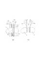
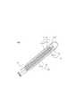
도 1은 본 발명에 따른 외과용 선형 스테이플러의 제1 실시 예를 나타낸 도면이다.
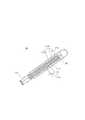
도 2는 도 1의 스테이플러에 구비된 스테이플러용 말단장치의 요부를 나타낸 도면이다.
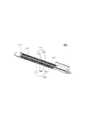
도 3은 도 2의 스테이플러용 말단장치에 구비된 카트리지 본체를 나타낸 도면이다.
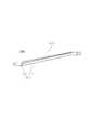
도 4는 도 2의 스테이플러용 말단장치에 구비된 단위 스테빌라이저를 나타낸 도면이다.
도 5는 도 2의 스테이플용 말단장치에 구비된 제1 푸셔와 제2 푸셔를 나타낸 도면이다.
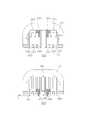
도 6은 도 2의 스테이플 말단장치에서 푸셔유닛 및 스테빌라이저유닛이 드라이빙 웨지에 의하여 가압되기 전과 가압된 후의 상태를 나타낸 단면이다.
도 7은 도 1의 스테이플러에 의하여 조직이 스테리플링되기 전과 절단된 후의 상태를 나타낸 도면이다.
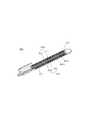
도 8은 본 발명에 따른 스테이플러용 말단장치의 제2 실시 예의 요부를 나타낸 도면이다.
도 9는 도 8의 스테이플 말단장치에 구비된 카트리지 본체를 나타낸 도면이다.
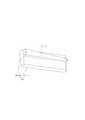
도 10은 도 8의 스테이플 말단장치에 구비된 스테빌라이저유닛을 나타낸 도면이다.
도 11은 본 발명에 따른 스테이플러용 말단장치의 제3 실시 예의 요부를 나타낸 도면이다.
도 12는 도 11의 스테이플 말단장치에 구비된 카트리지 본체를 나타낸 도면이다.
도 13은 도 11의 스테이플 말단장치에 구비된 단위 스테빌라이저를 나타낸 도면이다.
도 14는 도 11의 스테이플 말단장치에서 푸셔유닛 및 스테빌라이저유닛이 드라이빙 웨지에 의하여 가압되기 전과 가압된 후의 상태를 나타낸 단면이다.
도 15는 도 11의 스테이플 말단장치에 의하여 조직이 스테리플링되기 전과 절단된 후의 상태를 나타낸 도면이다.
도 16은 본 발명에 따른 스테이플러용 말단장치의 제4 실시 예의 요부를 나타낸 도면이다.
도 17은 도 16의 스테이플 말단장치에 구비된 카트리지 본체를 나타낸 도면이다.
도 18은 도 16의 스테이플 말단장치에 구비된 스테빌라이저유닛을 나타낸 도면이다.
도 19는 본 발명에 따른 스테이플러용 말단장치의 제5 실시 예의 요부를 나타낸 도면이다.
도 20은 도 19의 스테이플 말단장치에 구비된 카트리지 본체를 나타낸 도면이다.
도 21은 도 19의 스테이플 말단장치에 구비된 단위 스테빌라이저를 나타낸 도면이다.
도 22는 본 발명에 따른 스테이플러용 말단장치의 제6 실시 예에 구비된 엔빌을 나타낸 도면이다.
도 23은 본 발명에 따른 스테이플러용 말단장치의 제7 실시 예에 구비된 엔빌을 나타낸 도면이다.
도 24는 본 발명에 따른 스테이플러용 말단장치의 제8 실시 예의 요부를 나타낸 도면이다.
도 25는 본 발명에 따른 스테이플러용 말단장치의 제9 실시 예에 구비된 엔빌을 나타낸 도면이다.
도 26은 본 발명에 따른 스테이플러용 말단장치의 제10 실시 예에 구비된 엔빌을 나타낸 도면이다.
도 27은 도 24의 스테이플러용 말단장치의 8 실시 예에 사용되는 스테빌라이저유닛 및 푸셔유닛을 대체할 수 있는 푸셔 겸용 스테빌라이저유닛을 나타낸 도면이다.1 is a view showing a first embodiment of a surgical linear stapler according to the present invention.
FIG. 2 is a view showing a main part of a stapler end device provided in the stapler of FIG. 1. FIG.
FIG. 3 is a view showing a cartridge body provided in the end device for stapler of FIG. 2. FIG.
FIG. 4 is a view showing a unit stabilizer provided in the stapler end device of FIG. 2. FIG.
FIG. 5 is a view showing a first pusher and a second pusher provided in the staple end device of FIG. 2;
Fig. 6 is a cross-sectional view of the staple end device of Fig. 2 showing the state before and after the pusher unit and stabilizer unit are pressed by the driving wedge;
Fig. 7 is a view showing the state before and after the stapling of the tissue by the stapler of Fig. 1 and after the stapling. Fig.
8 is a view showing a main part of a second embodiment of a stapler end device according to the present invention.
FIG. 9 is a view showing a cartridge body provided in the staple end device of FIG. 8. FIG.
10 is a view showing a stabilizer unit provided in the staple end device of FIG.
11 is a view showing a main part of a third embodiment of a stapler end device according to the present invention.
FIG. 12 is a view showing a cartridge body included in the staple end device of FIG. 11. FIG.
FIG. 13 is a view showing a unit stabilizer provided in the staple end device of FIG. 11. FIG.
Fig. 14 is a cross-sectional view showing a state before and after the pusher unit and the stabilizer unit are pressed by the driving wedge in the staple end device of Fig. 11; Fig.
Fig. 15 is a view showing a state before and after tissue is stapled by the staple end device of Fig. 11; Fig.
16 is a view showing a main part of a fourth embodiment of a stapler end device according to the present invention.
FIG. 17 is a view showing a cartridge body provided in the staple end device of FIG. 16;
FIG. 18 is a view showing a stabilizer unit provided in the staple end device of FIG. 16;
Fig. 19 is a view showing a main portion of a fifth embodiment of a stapler end device according to the present invention. Fig.
Fig. 20 is a view showing a cartridge main body provided in the staple end device of Fig. 19;
FIG. 21 is a view showing a unit stabilizer provided in the staple end device of FIG. 19;
22 is a view showing an envelope provided in the sixth embodiment of the end device for a stapler according to the present invention.
23 is a view showing an envelope provided in the seventh embodiment of the end device for a stapler according to the present invention.
24 is a view showing a main part of an eighth embodiment of a stapler end device according to the present invention.
25 is a view showing an envelope provided in the ninth embodiment of the end device for a stapler according to the present invention.
26 is a view showing an envelope provided in the tenth embodiment of the end device for a stapler according to the present invention.
Fig. 27 is a view showing a stabilizer unit used in the eighth embodiment of the stapler end device of Fig. 24 and a pusher-combining stabilizer unit that can replace the pusher unit. Fig.
이하, 상술한 해결하고자 하는 과제가 구체적으로 실현될 수 있는 본 발명의 바람직한 실시 예들이 첨부된 도면을 참조하여 설명된다. 본 실시 예들을 설명함에 있어서, 동일 구성에 대해서는 동일 명칭 및 동일 부호가 사용되며 이에 따른 부가적인 설명은 하기에서 생략된다.Hereinafter, preferred embodiments of the present invention in which the above-mentioned problems to be solved can be specifically realized will be described with reference to the accompanying drawings. In describing the embodiments, the same names and the same symbols are used for the same configurations, and additional description therefor will be omitted below.
도 1 내지 도 7을 참조하여, 본 발명에 따른 병리검사용 조직을 획득할 수 있는 외과용 선형 스테이플러 및 스테이플러용 말단장치의 제1 실시 예를 설명하면 다음과 같다.1 to 7, a first embodiment of a surgical linear stapler and a stapler end device capable of obtaining a tissue for pathological examination according to the present invention will be described.
도 1을 참조하면, 상기 외과용 선형 스테이플러는 핸들어셈블리, 연장샤프트(5) 및 스테이플러용 말단장치를 포함한다.Referring to Fig. 1, the surgical linear stapler includes a handle assembly, an
상기 핸들어셈블리는 지지손잡이(1), 조작손잡이(2), 당김손잡이(3), 회전헤드(4) 및 컨트롤바(미도시)를 포함한다.The handle assembly includes a
상기 컨트롤바는 상기 연장샤프트(5) 및 상기 회전헤드(4)를 관통하면서 상기 조작손잡이(2)와 연동되도록 연결됨과 동시에 당김손잡이(3)와 연결된다. The control bar is connected to the pulling
상기 컨트롤바는 상기 조작손잡이(2)의 조작에 의해 전방으로 이동되고, 상기 당김손잡이(3)를 사용자가 후방으로 잡아당김에 따라 후방으로 이동한다.The control bar is moved forward by the operation of the
상기 회전헤드(4)는 상기 핸들어셈블리의 전방영역에 배치되며, 상기 컨트롤바를 내장한 상태로 상기 핸들어셈블리의 전방영역에서 상기 연장샤프트(5) 및 스테이플러용 말단장치를 360°회전시키게 된다.The
상기 연장샤프트(5)는 상기 스테이플러용 말단장치와 상기 회전헤드(4) 사이에 배치되며, 상기 연장샤프트(5)의 내부에는 상기 컨트롤바의 일부분이 배치된다.The
도 1 내지 도 7을 참조하면, 상기 스테이플러용 말단장치는 스테이플링 샤프트(10), 스테이플 카트리지 어셈블리(20), 앤빌(600), 푸셔유닛(200), 드라이빙 웨지(300), 스테빌라이저유닛(400) 및 블레이드(510) 갖는 블레이드유닛을 포함한다.1 to 7, the stapler end device includes a stapling
상기 스테이플 카트리지 어셈블리(20)는 스테이플 카트리지(100), 상기 스테이플 카트리지(100)의 상부에 배치되는 상부커버(21), 상기 상부커버(21)상에 구비되는 식별수단(23)을 포함하며, 상기 스테이플 카트리지(100)에는 조직(A)을 스테이플링하기 위한 스테이플이 내장되어 있다.The
상기 앤빌(600)은 상기 스테이플 카트리지(100)와 대응되며, 상기 스테이플 카트리지(100)에서 토출되는 상기 스테이플을 성형하게 된다.The
상기 푸셔유닛(200)은 상기 스테이플 카트리지(100)상에서 상기 스테이플과 대응되게 배치되되, 외력에 의하여 이동되면서 상기 스테이플 카트리지(100)의 높이방향인 제1 방향(Z)으로 상기 스테이플을 밀어내어 상기 스테이플 카트리지(100)로부터 토출시키게 된다.The
상기 드라이빙 웨지(300)는 상기 스테이플 카트리지(100)상에 배치되어 외력에 의하여 상기 스테이플 카트리지(100)의 길이방향인 제2 방향(X)을 따라 이동하면서 상기 푸셔유닛(200)을 상기 제1 방향(Z)으로 가압하게 된다.The driving
상기 스테빌라이저유닛(400)은 상기 스테이플 카트리지(100)상에 상기 푸셔유닛(200)과 이웃하여 배치되되, 상기 드라이빙 웨지(300)에 의하여 상기 스테이플 카트리지(100)로부터 적어도 일부분이 토출되어 상기 스테이플 카트리지(100)와 상기 앤빌(600) 사이에 배치되는 조직을 잡아주게 된다.The
상기 블레이드유닛은 상기 스테이플에 의하여 스테이플링된 조직을 절단하는 블레이드(510)를 가지며, 상기 제2 방향(X)을 따라 상기 드라이빙 웨지(300)를 이동시키게 된다.The blade unit has a
구체적으로, 도 3 및 도 7을 참조하면, 상기 스테이플 카트리지(100)는 카트리지 본체(110)를 포함하며, 상기 카트리지 본체(110)에는 제1 가이드슬릿(120), 제1 스테이플 토출공 집합체(130), 제2 스테이플 토출공 집합체(140) 및 스테빌라이저 토출슬릿(150)이 형성된다.3 and 7, the
상기 제1 가이드슬릿(120)은 상기 스테이플 카트리지(100)의 길이방향인 제2 방향(X)을 따라 상기 카트리지 본체(110)의 중심영역에 형성되어 상기 블레이드(510)의 이동을 안내하게 된다.The first guide slit 120 is formed in a central region of the
상기 스테빌라이저 토출슬릿(150)은 상기 제1 스테이플 토출공 집합체(130)와 상기 제1 가이드슬릿(120) 사이에 형성되어 상기 스테빌라이저유닛(400)의 적어도 일부분이 토출되는 통로역할을 하게 된다.The stabilizer discharge slit 150 is formed between the first
상기 스테빌라이저 토출슬릿(150)은 상기 제2 방향(X)을 따라 일정 간격으로 형성되는 복수 개의 단위 토출슬릿들을 포함하고, 상기 제2 방향(X)에 따른 상기 단위 토출슬릿의 길이는 상기 제2 방향(X)에 따른 제1 단위 스테이플 토출공의 길이보다 길게 형성된다. The
물론, 본 발명은 이에 한정되지 않고, 상기 스테빌라이저 토출슬릿(150)의 폭은 상기 제1 단위 스테이플 토출공의 폭과 다른 값을 가질 수 있다.Of course, the present invention is not limited to this, and the width of the
상기 제1 스테이플 토출공 집합체(130) 및 제2 스테이플 토출공 집합체(140)는 상기 제1 가이드슬릿(120)을 기준으로 양측에 배치되되, 상기 제1 스테이플 토출공 집합체(130)는 상기 스테빌라이저 토출슬릿(150)과 이웃하게 배치된다.The first
상기 제1 스테이플 토출공 집합체(130)는 상기 제1 가이드슬릿(120)을 기준으로 상기 스테이플 카트리지(100)의 폭방향인 제3 방향(Y)을 따라 일정간격으로 배치되는 복수 개의 제1 스테이플 토출공라인들을 포함한다. The first
구체적으로, 상기 제1 스테이플 토출공 집합체(130)는 상기 제1 가이드슬릿(120)으로부터 가장 인접하게 배치되는 제1-1 스테이플 토출공라인(131)과, 상기 제3 방향(Y)을 따라 상기 제1-1 스테이플 토출공라인(131)과 일정간격 떨어진 위치에 배치되는 제1-2 스테이플 토출공라인(132)을 포함한다.Specifically, the first
상기 제1-1 스테이플 토출공라인(131)은 하나의 열을 형성하면서 상기 제2 방향(X)을 따라 상기 카트리지 본체(110)에 일정간격으로 형성되는 복수 개의 제1 단위 스테이플 토출공들을 포함한다.The first staple
또한, 상기 제2 스테이플 토출공 집합체(140)는 상기 제1 가이드슬릿(120)으로부터 가장 인접하게 배치되는 제2-1 스테이플 토출공라인(141)과, 상기 제3 방향(Y)과 반대방향인 제4방향(Y')을 따라 상기 제2-1 스테이플 토출공라인(141)과 일정간격 떨어진 위치에 배치되는 제2-2 스테이플 토출공라인(142)과, 상기 제4 방향을 따라 상기 제2-2 스테이플 토출공라인(142)과 일정간격 떨어진 위치에 배치되는 제2-3 스테이플 토출공라인(143)을 포함한다.The second
상기 제1-1 스테이플 토출공라인(131)과 상기 제1 가이드슬릿(120) 사이의 제1 거리는 상기 제2-1 스테이플 토출공라인(141)과 상기 제1 가이드슬릿(120) 사이의 제2 거리보다 크게 형성된다.The first distance between the first staple
상기 제1-1 스테이플 토출공라인(131)에 내장되어 있는 스테이플들은 상기 푸셔유닛(200)에 의하여 토출되고, 상기 앤빌(600)에 의하여 성형되면서 상기 조직상에서 제1 스테이플링선(1aa)을 형성하게 되고, 상기 제2-1 스테이플 토출공라인(141)에 내장되어 있는 스테이플들은 제2 스테이플링선(3aa)을 형성하게 된다.The staples contained in the first staple
따라서, 상기 조직(A)이 절단되는 절단면(A1)에서 상기 제1 스테이플링선(1aa)까지의 거리(D1)가 상기 절단면(A1)에서 상기 제2 스테이플링선(3aa)까지의 거리(D2)보다 크게 형성된다.The distance D1 from the cut surface A1 at which the tissue A is cut to the first staple line 1aa is smaller than the distance D2 from the cut surface A1 to the second staple line 3aa, .
결과적으로, 상기 절단면(A1)과 상기 제1 스테이플링선(1aa) 사이의 조직은 스테이플에 의하여 손상되지 않게 됨으로써 상기 블레이드(510)에 의하여 제거되는 조직 중에서 상기 스테이플에 의하여 손상되지 않은 병리검사용 조직영역이 얻어지게 된다.As a result, the tissue between the cut surface A1 and the first staple line 1aa is not damaged by the staple, so that the tissues removed by the
구체적으로, 도 7의 (a)에 도시된 바와 같이, 상기 카트리지 본체(110)상에 배치되는 조직의 수술부위(A)는 상기 블레이드(510)에 의하여 가상 절단선(A0)을 기준으로 두 개의 수술부위로 절단된다. 상기 두 개의 수술부위 중 하나는 제거되는 제1 수술부위(C)이고, 나머지 하나는 인체에 잔존하는 제2 수술부위(B)이다.7A, the surgical site A of the tissue placed on the cartridge
본 실시 예에 따른 스테이플러용 말단장치가 작동되면, 도 7의 (b)에서와 같이, 상기 제1 수술부위(C)는 절단면(A1)과 평행한 2열의 스테이플링선을 가지게 되고, 상기 제2 수술부위(B)는 상기 절단면(A1)과 평행한 3열의 스테이플링선을 가지게 된다.When the end device for stapler according to the present embodiment is operated, as shown in FIG. 7 (b), the first surgical region C has two rows of staple lines parallel to the cut surface A1, The surgical site B has three rows of staple lines parallel to the cut surface A1.
상기 제1 수술부위(C)의 스테이플링선들 중 상기 절단면(A1)에 가장 가까운 상기 제1 스테이플링선(1aa)과 상기 절단면(A1) 사이의 거리(D1)는 상기 제2 수술부위(B)의 스테이플링선들 중 상기 절단면(A1)에 가장 가까운 제2 스테이플링선(3aa)과 상기 절단면(A1) 사이의 거리(D2)보다 큰 값을 가진다.A distance D1 between the first stapling line 1aa closest to the cut surface A1 and the cut surface A1 among the staple lines of the first surgical site C is smaller than a distance D1 between the second staple line B and the cut surface A1, And a distance D2 between the second staple line 3aa closest to the cut surface A1 and the cut surface A1.
따라서, 상기 제1 수술부위(C) 중 상기 절단면(A1)에서 상기 제1 스테이플링선(1aa) 사이에 있는 생체조직은 상기 스테이플에 의하여 전혀 손상되지 않기 때문에 상기 병리검사용 조직으로 적합하게 된다.Therefore, the biotissue between the first staple line 1aa and the cut surface A1 of the first surgical site C is not damaged at all by the staples, which is suitable for the pathology examination.
결과적으로, 하나의 장기를 두 영역으로 절단 및 스테이플링하는 과정에서 절단면을 기준으로 제거되는 장기부위의 스테이플링선까지의 거리가 인체에 남는 수술부위의 스테이플링선까지의 거리보다 큰 값을 가지도록 함으로써 제거되는 수술부위에서 조직검사를 위한 생체조직의 절단마진이 손상되지 않게 된다. 이로써, 제거되는 장기의 수술부위에서 스테이플에 의하여 손상되지 않는 병리검사용 조직영역을 안정적이면서도 간편하게 확보할 수 있게 된다.As a result, in the process of cutting and stapling one organ to two regions, the distance to the staple line of the organ to be removed based on the cutting plane is larger than the distance to the staple line of the surgical site remaining in the human body The cutting margin of the biopsy for histological examination at the removed surgical site is not damaged. Thereby, it is possible to stably and easily secure a tissue area for pathological examination that is not damaged by the staple at the surgical site of the organs to be removed.
특히, 상기 스테이플 카트리지(100)와 상기 앤빌(600)이 상대이동하면서 상기 조직을 스테이플링 할 때 상기 스테빌라이저유닛(400)이 상기 스테이플 카트리지(100)로부터 토출되면서 상기 조직의 절단면(A1)과 상기 제1 스테이플링선(1aa) 사이의 조직을 잡아줌으로 인하여 상기 조직이 찢어지지 않은 상태에서 상기 블레이드(510)가 상기 조직을 안정적으로 절단할 수 있게 된다.Particularly, when the
도 1 내지 도 3을 참조하면, 상기 식별수단(23)은 상기 스테이플 카트리지(100)상에서 상기 제1 가이드슬릿(120)을 기준으로 상기 스테빌라이저유닛(400)이 배치된 영역의 위치를 표시하게 된다. 여기서, 상기 스테빌라이저유닛(400)과 상기 앤빌(600) 사이에 배치되는 조직은 스테이플에 의하여 스테이플링되지 않기 때문에 조직이 손상되지 않게 된다.1 to 3, the identification means 23 displays the position of the area where the
결과적으로, 상기 식별수단(23)은 상기 조직이 상기 블레이드(510)에 의하여 절단되는 과정에서 손상되지 않은 병리검사용 조직영역이 포함되는 조직, 즉 인체에서 제거되는 조직이 어느 위치에 있는지를 알려주게 되고, 이로 인하여 수술 중의 착오를 방지할 수 있게 된다.As a result, in the process of cutting the tissue by the
상기 식별수단(23)은 상기 상부커버(21)의 외측면에 특정색깔로 페인팅되거나, 외부에서 식별가능한 색깔을 갖는 테이프, 모양을 갖는 돌기 등의 형태로 상기 상부커버(21)에 구비될 수 있다. 물론, 상기 식별수단(23)은 형광물질이 포함된 재료로 제작되거나, 엘이디(LED)와 같은 조명의 형태로 제공될 수도 있을 것이다.The identification means 23 may be painted with a specific color on the outer surface of the
도 2, 도 4 및 도 6을 참조하면, 상기 스테빌라이저유닛(400)은 상기 제2 방향(X)을 따라 일정 간격으로 배치되는 복수 개의 단위 스테빌라이저들을 포함한다.Referring to FIGS. 2, 4 and 6, the
구체적으로, 상기 스테빌라이저유닛(400), 즉 단위 스테빌라이저는 상기 조직과 접촉하게 되는 접촉부재(410)와, 상기 접촉부재(410)의 일측에서 연장형성되며 상기 드라이빙 웨지(300)에 의하여 가압되는 피가압부재(420)를 포함한다.Specifically, the
상기 접촉부재(410)는 상기 피가압부재(420)에서 연장형성되는 상부몸체(413)와, 상기 상부몸체에서 연장되면서 상기 스테이플 카트리지(100)로부터 토출되어 상기 조직과 직접적으로 접촉하는 하부몸체(411)를 포함한다.The
상기 하부몸체(411)는 상기 조직의 손상을 방지하기 위하여 상기 하부몸체의 하단부 중심영역(411a)을 향하여 완만하게 형성되는 굴곡면(411b)을 가진다.The
상세하게는, 상기 하부몸체(411)의 단면 중 상기 제2 방향(X)과 평행하는 단면은 라운드진 직사각형의 형태를 가지며, 상기 하부몸체의 하단부 중심영역(411a)으로 갈수록 단면폭이 작아지게 형성된다.A cross section of the cross section of the
여기서, 상기 하부몸체의 하단부 중심영역(411a)은 상기 제2 방향(X)을 따라 좁은 폭을 가지면서 평면이 될 수도 있고, 하나의 중심선의 형태가 될 수도 있다.Here, the lower end
도 2 및 도 4에 도시된 것과 같이, 상기 피가압부재(420)는 상기 접촉부재(410)의 일단에서 절곡되어 연장형성되고, 상기 피가압부재(420)의 높이는 상기 제2 방향(X)을 따라 점차적으로 높아지도록 형성된다.2 and 4, the pressured
상기 피가압부재(420) 중 일단부의 높이는 상기 일단부와 반대편에 배치되는 타단부의 높이보다 작은 값을 가진다. 여기서, 상기 피가압부재(420)의 일단부는 상기 피가압부재 중 상기 스테이플링 샤프트(10)와 가까운 거리에 배치되는 단부를 의미한다. The height of one end of the
따라서, 본 실시 예에 따른 상기 스테빌라이저유닛(400)의 전체높이는 상기 제2 방향(X)을 따라 점차적으로 높아지도록 형성된다. 도 4를 기준으로, S1이 S2 보다 작은 값을 가진다.Therefore, the overall height of the
상기 접촉부재(410)의 높이는 상기 제2 방향(X)을 따라 일정하게 형성되어, 상기 접촉부재(410) 중 상기 스테이플 카트리지(100)부터 토출되는 영역이 일정한 토출높이를 가지게 된다.The height of the
도 2, 도3, 도 5 및 도 6을 참조하면, 상기 푸셔유닛(200)은 상기 제1 스테이플 토출공 집합체(130)에 내장되어 있는 스테이플들을 상기 제1 방향(Z)으로 가압시키기 위한 제1 푸셔(210)와, 상기 제2 스테이플 토출공 집합체(140)에 내장되어 있는 스테이플들을 상기 제1 방향(Z)으로 가압시키기 위한 제2 푸셔(220)를 포함한다.Referring to FIGS. 2, 3, 5 and 6, the
상기 제1 푸셔(210)는 상기 제2 방향(X)을 따라 일정간격으로 배치되는 복수 개의 제1 단위푸셔들을 포함하고, 상기 제2 푸셔(220)는 상기 제2 방향을 따라 일정간격으로 배치되는 복수 개의 제2 단위푸셔들을 포함한다.The
도 5의 (a)를 참조하면, 상기 제1 푸셔(210)는 상기 제1-1 스테이플 토출공라인(131)에 내장되어 있는 제1-1 스테이플을 가압하기 위한 제1-1 푸셔부(211)와, 상기 제1-2 스테이플 토출공라인(132)에 내장되어 있는 제1-2 스테이플을 가압하기 위한 제1-2 푸셔부(213)와, 상기 제1-1 푸셔부(211)와 상기 제1-2 푸셔부(213)를 연결하는 제1 푸셔연결부(214)와, 상기 드라이빙 웨지(300)에 의하여 가압되는 제1 푸셔가압부(212)를 포함한다.Referring to FIG. 5A, the
상기 제1-1 푸셔부(211)는 제1-1 스테이플의 본체를 가압하기 위한 제1-1 본체가압부(211b)와, 제1-1 스테이플의 다리를 가압하기 위하여 상기 제1-1 본체가압부(211b)의 양측면으로 돌출된 제1-1 다리가압부(211a)를 포함한다.The
상기 제1-2 푸셔부(213)는 제1-2 스테이플의 본체를 가압하기 위한 제1-2 본체가압부(213b)와, 제1-2 스테이플의 다리를 가압하기 위하여 상기 제1-2 본체가압부(213b)의 양측면으로 돌출된 제1-2 다리가압부(213a)를 포함한다.The second 1-2 pusher portion 213 includes a pressing portion 213b for pressing the main body of the first staple and a second pressing portion 213b for pressing the main portion of the first staple, The main body includes a
상기 제1-1 본체가압부(211b)의 하단면과 상기 제1-2 본체가압부(213b)의 하단면은 각각 제1-1 스테이플의 본체 및 제1-1 스테이플의 본체를 가압하여야 하기 때문에 평면 형상을 가져야 한다.The lower end surface of the
또한, 상기 제1-1 다리가압부(211a) 및 상기 제1-2 다리가압부(213a)는 카트리지 본체(110)에 형성된 스테이플 설치홈(미도시)에 끼워진 상태에서 상기 제1-1 스테이플과 제1-2 스테이플을 가압하게 된다.The first 1-1
상기 제1-1 푸셔부(211)와 상기 제1-2 푸셔부(213)는 상기 제1 푸셔연결부(214)을 통하여 일체로 형성되되, 상기 제2 방향(X)과 평행한 상기 제1 푸셔(210)의 중심라인을 기준으로 비대칭적으로 형성된다.The
도 5의 (b)를 참조하면, 상기 제2 푸셔(220)는 상기 제2 방향(X)과 평행한 상기 제2 푸셔(220)의 중심라인을 기준으로 대칭적으로 배치되는 제2-1 푸셔부(221) 및 제2-3 푸셔부(223)와, 상기 제2-1 푸셔부(221) 및 상기 제2-3 푸셔부(223)의 전단방향, 즉 상기 제2 방향으로 연장형성되되 상기 제2 푸셔(220)의 폭방향을 기준으로 중심영역에 형성되는 제2-2 푸셔부(222)를 포함한다.Referring to FIG. 5B, the
상기 제2-1 푸셔부(221), 제2-2 푸셔부(222) 및 상기 제2-3 푸셔부(223)는 외력에 의하여 이동하면서 상기 제2-1 스테이플 토출공라인(141), 상기 제2-2 스테이플 토출공라인(142) 및 상기 제2-3 스테이플 토출공라인(143)에 각각 내장되어 있는 제2-1 스테이플, 제2-2 스테이플 및 제2-3 스테이플을 각각 가압하게 된다.The second-1
상기 제2-1 푸셔부(221), 제2-2 푸셔부(222) 및 상기 제2-3 푸셔부(223)의 세부적인 형상은 상기 제1-2 푸셔부(213)와 실질적으로 동일하므로 이에 대한 상세한 설명은 생략한다.The detailed shapes of the second-
여기서, 상기 제2 방향(X)에 따른 상기 단위푸셔의 길이는 상기 단위 스테빌라이저의 길이보다 작게 형성된다. 즉, 상기 제2 방향(X)에 따른 상기 스테빌라이저유닛의 단위 스테빌라이저의 길이는 단위 스테이플 토출공과 대응되는 단위 푸셔의 길이보다 길게 형성된다.Here, the length of the unit pusher along the second direction X is smaller than the length of the unit stabilizer. That is, the length of the unit stabilizer of the stabilizer unit along the second direction X is longer than the length of the unit pusher corresponding to the unit staple discharge hole.
또한, 상기 제1 방향에 따른 상기 스테빌라이저유닛(400)의 높이(H2)는 상기 푸셔유닛(200)의 높이(H1)보다 높게 형성되어 상기 스테빌라이저유닛(400)이 상기 스테이플 카트리지로부터 토출되는 제1 토출높이(H4)가 상기 푸셔유닛(200)이 상기 스테이플 카트리지(100)로부터 토출되는 제2 토출높이(H3)보다 크게 형성된다.The height H2 of the
상기 제2 토출높이(H3)는 0.1 ~ 1mm 정도 이고, 상기 제1 토출높이(H4)는 0.12~1.25mm 정도로 형성된다. 물론, 상기 제1 토출높이와 상기 제2 토출높이는 동일하게 형성될 수도 있을 것이다.The second discharge height H3 is about 0.1 to 1 mm, and the first discharge height H4 is about 0.12 to 1.25 mm. Of course, the first ejection height and the second ejection height may be the same.
상기 스테빌라이저유닛(400)과 상기 앤빌(600)의 사이에는 조직이 직접적으로 배치되지만, 상기 푸셔유닛(200)과 상기 앤빌(600)사이에는 스테이플이 배치되어 있기 때문에 상기 제1 토출높이(H4)가 상기 스테이플의 두께만큼 상기 제2 토출높이보다 높아야만 상기 앤빌(600)과 상기 스테이플 카트리지(100) 사이의 조직이 안정적으로 잡혀지게 되고, 이러한 상태에서 상기 조직은 찢어짐이 없이 상기 블레이드에 의하여 안전하게 절단될 수 있다.Since the staple is disposed between the
도 2 및 도 6을 참조하면, 상기 드라이빙 웨지(300)는 웨지본체(310), 제1 웨지(320), 제2 웨지(330), 제3 웨지(340), 제4 웨지(350) 및 가이드웨지(360)를 포함한다.2 and 6, the driving
상기1 웨지(320)는 상기 웨지본체(310)에서 하부방향으로 돌출되어 연장형성되며, 외력에 의하여 이동되면서 상기 제1 푸셔(210)를 가압하게 된다.The
상기 제2 웨지(330)는 상기 제1 웨지(320)와 이웃하게 배치되어 상기 웨지본체(310)에서 하부방향으로 돌출되어 연장형성되며, 상기 스테빌라이저유닛(400)을 가압하게 된다.The
상기 가이드웨지(360)는 상기 웨지본체의 중심영역에서 하부로 연장형성되며, 상기 카트리지 본체(110)의 내부에 형성된 슬릿을 따라 상기 제2 방향(X)으로 이동하게 된다.The
상기 제3 웨지(340) 및 상기 제4 웨지(350)는 상기 웨지본체(310)로부터 하부방향으로 돌출되어 연장형성되되, 상기 가이드웨지(360)를 기준으로 상기 제1 웨지(320) 및 제2 웨지(330)의 반대방향에 형성된다. 여기서, 상기 제3 웨지(340) 및 상기 제4 웨지(350)는 상기 제2 푸셔(220)를 가압하게 된다.The
본 실시 예에서 상기 제1 방향(Z)에 따른 상기 제1 웨지(320)의 돌출높이와 상기 제2 웨지(330)의 돌출높이는 동일하지만, 본 발명은 이에 한정되지 않고, 상기 제2 웨지(330)의 돌출높이는 상기 제1 웨지(320)의 돌출높이보다 크게 형성될 수 있다. 또한, 상기 웨지들은 서로 분리되어 개별적으로 형성될 수도 있을 것이다.The protrusion height of the
상기 스테빌라이저유닛(400)과 상기 푸셔유닛(200)이 동일한 높이를 가지는 경우에 상기 제2 웨지(330)의 돌출높이가 상기 제1 웨지(320)의 돌출높이보다 크게 형성됨으로써 상기 스테빌라이저유닛(400)이 상기 스테이플 카트리지(100)로부터 토출되는 제1 토출높이(H4)가 상기 푸셔유닛(200)이 상기 스테이플 카트리지(100)로부터 토출되는 제2 토출높이(H3)보다 크게 형성될 수 있다.When the
본 실시 예에 따른 스테이플러용 말단장치는 상기 스테이플 카트리지 어셈블리가 상부에 위치하고, 상기 앤빌이 상기 스테이플 카트리지 어셈블리의 하부에 위치되는 형태를 가진다. 그러나, 본 발명에 따른 스테이플러용 말단장치는 상기 앤빌이 상부에 배치되고 상기 스테이플 카트리지 어셈블리가 하부에 배치되는 경우를 포함한다.The end device for a stapler according to the present embodiment has a configuration in which the staple cartridge assembly is located at an upper portion and the anvil is located at a lower portion of the staple cartridge assembly. However, the end device for a stapler according to the present invention includes a case where the anvil is disposed on the upper side and the staple cartridge assembly is disposed on the lower side.
도 8 내지 도 10을 참조하여, 본 발명에 따른 스테이플러용 말단장치의 제2 실시 예를 설명한다. 본 실시 예에 따른 스테이플러용 말단장치는 상술한 스테이플러용 말단장치의 제1 실시 예와 실질적으로 유사한 구성을 가진다.A second embodiment of a stapler end device according to the present invention will be described with reference to Figs. 8 to 10. Fig. The end device for stapler according to the present embodiment has a configuration substantially similar to that of the first embodiment of the end device for stapler described above.
다만, 본 실시 예에 따른 스테이플러용 말단장치는 상술한 제1 실시 예와 달리, 스테빌라이저유닛(1400)이 복수 개의 단위 스테빌라이저들로 구성되는 것이 아니라 상기 제2 방향을 따라 길게 하나로 형성되어 카트리지 본체(110)에 구비된다.However, unlike the first embodiment, the
따라서, 상기 카트리지 본체(110)에도 제1 가이드슬릿(120)과 제1 스테이플 토출공 집합체(130)의 사이에 상기 제2 방향을 따라 하나의 스테빌라이저 토출슬릿(1150)이 길게 형성된다.Accordingly, the
상기 스테빌라이저유닛(1400)의 단면 형상은 상술한 제1 실시예에 따른 스테빌라이저유닛의 단면형상과 실질적으로 동일하다. 구체적으로, 상기 스테빌라이저유닛(1400)은 접촉부재(1410), 피가압부재(1420)를 포함하며, 상기 접촉부재(1410)는 상부몸체(1413) 및 하부몸체(1411)를 포함하고, 상기 하부몸체(1411)는 상기 조직의 손상을 방지하기 위하여 상기 하부몸체의 하단부 중심영역을 향하여 완만하게 형성되는 굴곡면을 가진다.The sectional shape of the
본 실시 예에 따른 상기 스테빌라이저유닛(1400)의 전체높이는 상기 제2 방향(X)을 따라 점차적으로 높아지도록 형성된다. 도 10을 기준으로, S3이 S4 보다 작은 값을 가진다.The overall height of the
상기 스테빌라이저유닛(1400)이 하나의 부재로 상기 제2 방향(X)을 따라 길게 형성됨으로써 상기 스테이플 카트리지(100)와 상기 앤빌(600) 사이에 배치되는 조직을 한꺼번에 잡아주게 된다.The
도 11 내지 도 15를 참조하여, 본 발명에 따른 스테이플러용 말단장치의 제3 실시 예를 설명한다. 본 실시 예에 따른 스테이플러용 말단장치는 상술한 스테이플러용 말단장치의 제1 실시 예와 실질적으로 유사한 구성을 가진다.A third embodiment of the stapler end device according to the present invention will be described with reference to Figs. 11 to 15. Fig. The end device for stapler according to the present embodiment has a configuration substantially similar to that of the first embodiment of the end device for stapler described above.
다만, 본 실시 예에 따른 스테이플러용 말단장치에 구비되는 스테빌라이저유닛(2400)은 스테이플 카트리지(100)상에 배치되되, 제1 가이드슬릿(120)을 기준으로 양측에 배치되는 제1 스테빌라이저(2410) 및 제2 스테빌라이저(2420)를 포함한다.However, the
상기 제1 스테빌라이저(2410)는 복수 개의 제1 단위 스테빌라이저들을 포함하고, 상기 제2 스테빌라이저(2420)도 복수 개의 제1 단위 스테빌라이저들을 포함하며, 상기 제1 단위 스테빌라이저의 형상은 상기 제2 스테빌라이저의 형상과 동일하다.The
상기 제1 단위 스테빌라이저는 조직과 접촉하게 되는 접촉부재(2411)와, 상기 접촉부재(2411)의 일측에서 연장형성되며 드라이빙 웨지(300)에 의하여 가압되는 피가압부재(2413)를 포함한다.The first unit stabilizer includes a
상기 접촉부재(2411)는 상기 피가압부재(2413)에서 연장형성되는 상부몸체(2411b)와, 상기 상부몸체에서 연장되면서 상기 스테이플 카트리지(100)로부터 토출되어 상기 조직과 직접적으로 접촉하는 하부몸체(2411a)를 포함한다.The
상기 하부몸체(2411a)는 상기 조직의 손상을 방지하기 위하여 상기 하부몸체의 하단부 중심영역을 향하여 완만하게 형성되는 굴곡면을 가진다.The
상기 피가압부재(2413)는 상기 접촉부재(2411)의 측면에서 돌출형성되고, 상기 피가압부재(2413)의 높이는 상기 제2 방향(X)을 따라 점차적으로 증가한다.The
상기 피가압부재(2413)가 상기 제2 방향(X)을 따라 점차적으로 증가하지만, 상기 접촉부재(2411)의 측면에서 돌출형성되어 있고, 상기 접촉부재(2411)의 높이는 상기 제2 방향(X)을 따라 일정한 높이를 가지므로 상기 제1 단위 스테빌라이저의 전체높이는 상기 제2 방향을 따라 일정하게 형성된다.The urging
한편, 상기 카트리지 본체(110)에는 상기 제1 가이드슬릿(120)을 기준으로 양측에 형성되는 제1 스테이플 토출공 집합체(1130) 및 제2 스테이플 토출공 집합체(1140)와, 상기 제1 스테이플 토출공 집합체(1130)와 상기 제1 가이드슬릿(120) 사이에 형성되어 상기 제1 스테빌라이저(2410)의 적어도 일부분이 토출되는 제1 스테빌라이저 토출슬릿(1161)과, 상기 제2 스테이플 토출공 집합체(1140)와 상기 제1 가이드슬릿(120) 사이에 형성되어 상기 제2 스테빌라이저(2420)의 적어도 일부분이 토출되는 제2 스테빌라이저 토출슬릿(1163)이 형성된다.The
한편, 푸셔유닛(1200) 상기 제1 스테이플 토출공 집합체(1130)에 내장되어 있는 스테이플들을 상기 제1 방향(Z)으로 가압시키기 위한 제1 푸셔(1210)와, 상기 제2 스테이플 토출공 집합체(1140)에 내장되어 있는 스테이플들을 상기 제1 방향(Z)으로 가압시키기 위한 제2 푸셔(1220)를 포함한다. 여기서, 상기 제1 푸셔(1210)와 상기 제2 푸셔(1220)는 동일한 형상을 가지며, 상술한 도 5의 (a)에 도시된 제1 푸셔(210)와 동일하므로 이에 대한 상세한 설명은 생략한다.The
도 14의 (a)는 상기 스테빌라이저유닛 및 상기 푸셔유닛이 드라이빙 웨지(300)에 의하여 가압되기 전의 상태를 나타내고, 도 14의 (b)는 상기 스테빌라이저유닛 및 상기 푸셔유닛이 상기 드라이빙 웨지(300)에 의하여 가압된 상태를 나타낸 도면이다.14 (a) shows a state before the stabilizer unit and the pusher unit are pressed by the driving
도 15의 (a)는 스테이플에 의하여 조직이 스테이플링되기 전의 상태를 나타낸 도면이고, 도 15의 (b)는 스테이플링 후 블레이드(510)에 의하여 조직이 절단된 상태를 나타내 도면이다.FIG. 15A is a view showing a state before a tissue is stapled by staples, and FIG. 15B is a view showing a state where a structure is cut by a
상기 제1 스테빌라이저(2410) 및 상기 제2 스테빌라이저(2420)가 상기 카트리지 본체(110)에 내장되어 있고, 상기 제1 스테이플 토출공 집합체(1130) 및 상기 제2 스테이플 토출공 집합체(1140)에 스테이플이 각각 내장된 상태에서 상기 드라이빙 웨지(300)에 의하여 상기 제1 푸셔(1210), 상기 제2 푸셔(1220), 상기 제1 스테빌라이저(2410) 및 상기 제2 스테빌라이저(2420)가 가압되면 도 15의 (b)에서와 같이 조직의 절단면(A1)을 기준으로 양측 조직에 각각 2 열의 스테이플링선들이 일정간격으로 생성된다.The
구체적으로, 도 15의 (a)에 도시된 바와 같이, 상기 카트리지 본체(110)상에 배치되는 조직의 수술부위(A)는 상기 블레이드(510)에 의하여 가상 절단선(A0)을 기준으로 두 개의 수술부위로 절단된다. 상기 두 개의 수술부위 중 하나는 제거되는 제1 수술부위(C)이고, 나머지 하나는 인체에 잔존하는 제2 수술부위(B)이다.Specifically, as shown in FIG. 15A, the surgical site A of the tissue disposed on the cartridge
본 실시 예에 따른 스테이플러용 말단장치가 작동되면, 도 15의 (b)에서와 같이, 상기 제1 수술부위(C)는 절단면(A1)과 평행한 2열의 스테이플링선을 가지게 되고, 상기 제2 수술부위(B)는 상기 절단면(A1)과 평행한 2열의 스테이플링선을 가지게 된다.When the end device for stapler according to the present embodiment is operated, as shown in FIG. 15 (b), the first surgical region C has two rows of staple lines parallel to the cut surface A1, The surgical site B has two rows of staple lines parallel to the cut surface A1.
상기 제1 수술부위(C)의 스테이플링선들 중 상기 절단면(A1)에 가장 가까운 상기 제1 스테이플링선(1aa)과 상기 절단면(A1) 사이의 거리(D1)는 상기 제2 수술부위(B)의 스테이플링선들 중 상기 절단면(A1)에 가장 가까운 제2 스테이플링선(3aa)과 상기 절단면(A1) 사이의 거리(D1)는 서로 동일한 값을 가진다.A distance D1 between the first stapling line 1aa closest to the cut surface A1 and the cut surface A1 among the staple lines of the first surgical site C is smaller than a distance D1 between the second staple line B and the cut surface A1, The distance D1 between the second staple line 3aa closest to the cut surface A1 and the cut surface A1 has the same value.
여기서, 상기 제1 스테이플링선(1aa)과 상기 제2 스테이플링선(3aa)은 모두 상기 절단면을 기준으로 일정거리 이상 떨어진 위치에 있게 됨으로써 제거되는 조직, 즉 상기 제1 수술부위(C) 중 상기 절단면(A1)에서 상기 제1 스테이플링선(1aa) 사이에 있는 생체조직은 상기 스테이플에 의하여 전혀 손상되지 않기 때문에 상기 병리검사용 조직으로 적합하게 된다.Here, the first staple line 1aa and the second staple line 3aa are both located at a predetermined distance or more away from the cut surface to remove tissue, that is, The living tissue between the first staple line 1aa and the first staple line 1aa is not damaged at all by the staple.
도 16 내지 도 18를 참조하여, 본 발명에 따른 스테이플러용 말단장치의 제4 실시 예를 설명한다. 본 실시 예에 따른 스테이플러용 말단장치는 상술한 스테이플러용 말단장치의 제3 실시 예와 실질적으로 유사한 구성을 가진다.A fourth embodiment of a stapler end device according to the present invention will be described with reference to Figs. 16 to 18. Fig. The end device for stapler according to the present embodiment has a configuration substantially similar to that of the third embodiment of the above-described end device for stapler.
다만, 다만, 본 실시 예에 따른 스테이플러용 말단장치는 상술한 제3 실시 예와 달리, 제1 스테빌라이저(3410) 및 제2 스테빌라이저(3420)가 복수 개의 단위 스테빌라이저들로 구성되는 것이 아니라 상기 제2 방향을 따라 길게 하나로 각각 형성되어 카트리지 본체(110)에 구비된다.However, unlike the third embodiment, the end device for a stapler according to the present embodiment is different from the third embodiment in that the
따라서, 상기 카트리지 본체(110)에도 제1 가이드슬릿(120)과 제1 스테이플 토출공 집합체(1130)의 사이에 상기 제2 방향(X)을 따라 하나의 제1 스테빌라이저 토출슬릿(1171)이 길게 형성되고, 상기 제1 가이드슬릿(120)과 제2 스테이플 토출공 집합체(1140) 사이에 상기 제2 방향(X)을 다라 하나의 제2 스테빌라이저 토출슬릿(1173)이 길게 형성된다.The
상기 제1 스테빌라이저(3410) 및 상기 제2 스테빌라이저(3420)의 단면 형상은 상술한 제3 실시예에 따른 스테빌라이저유닛에 구비된 제1 단위 스테빌라이저의 단면형상과 실질적으로 동일하므로 이에 대한 상세한 설명은 생략한다.Sectional shape of the
도 19 내지 도 21을 참조하여, 본 발명에 따른 스테이플러용 말단장치의 제5 실시 예를 설명한다. 본 실시 예에 따른 스테이플러용 말단장치는 상술한 스테이플러용 말단장치의 제1 실시 예와 실질적으로 유사한 구성을 가진다.19 to 21, a fifth embodiment of a stapler end device according to the present invention will be described. The end device for stapler according to the present embodiment has a configuration substantially similar to that of the first embodiment of the end device for stapler described above.
다만, 본 실시 예에 따른 스테이플러용 말단장치는 상술한 제1 실시 예와 달리, 카트리지 본체(110)의 길이방향인 제2 방향에 따른 스테빌라이저유닛의 단위 스테빌라이저의 길이, 푸셔유닛의 단위 푸셔의 길이, 제1 스테이플 토출공 집합체(2130) 및 제2 스테이플 토출공 집합체(2140)의 각각의 단위 스테이플 토출공의 길이가 실질적으로 동일하다.However, unlike the first embodiment described above, the end device for a stapler according to the present embodiment has a length of the unit stabilizer of the stabilizer unit according to the second direction which is the longitudinal direction of the main
구체적으로, 상기 스테빌라이저유닛(4400)은 상기 제2 방향(X)을 따라 일정 간격으로 배치되는 복수 개의 단위 스테빌라이저들을 포함하고, 상기 푸셔유닛(200)은 상기 제2 방향(X)을 따라 일정 간격으로 배치되는 복수 개의 단위 푸셔들을 포함한다.More specifically, the
상기 제1 스테이플 토출공 집합체(2130)는 복수 개의 제1 단위 스테이플 토출공들을 포함하고, 상기 스테빌라이저 토출슬릿(1180)은 제2 방향을 따른 복수 개의 단위 토출슬릿을 포함하며, 상기 제2 방향(X)에 따른 상기 단위 스테빌라이저의 길이는 상기 제2 방향(X)에 따른 상기 단위 푸셔의 길이와 실질적으로 동일하고, 상기 제2 방향(X)에 따른 상기 제1 단위 스테이플 토출공의 길이는 상기 제2 방향(X)에 따른 상기 단위 토출슬릿의 길이와 실질적으로 동일하게 형성된다.The first
여기서, 상기 푸셔유닛(200)은 상술한 제1 실시 예에서의 푸셔유닛과 실질적으로 동일하므로 이에 대한 상세한 설명은 생략한다. 상기 단위 스테빌라이저는 접촉부재(4410), 피가압부재(4420)를 포함하고, 상기 접촉부재(4410)는 상부몸체(4413) 및 하부몸체(4411)를 포함하며, 상기 하부몸체(4411)는 상기 조직의 손상을 방지하기 위하여 상기 하부몸체의 하단부 중심영역(4411a)을 향하여 완만하게 형성되는 굴곡면(4411b)을 가진다.Here, since the
한편, 본 실시 예에 따른 앤빌(600)은 앤빌본체(610)를 포함하며, 상기 앤빌본체(610)에는 블레이드(510)의 이동을 안내하는 제2 가이드슬릿(620)과, 상기 제2 가이드슬릿(620)을 기준으로 양측에 형성되는 제1 앤빌홈 집합체(630) 및 제2 엔빌홈 집합체(640)가 형성되어 있다.The
구체적으로, 상기 제1 앤빌홈 집합체(630)는 상기 제2 가이드슬릿(620)으로부터 가장 인접하게 배치되는 제1-1 앤빌홈 라인(631)과, 상기 제1-1 앤빌홈 라인(631)과 일정간격 떨어진 위치에 배치되는 제1-2 앤빌홈 라인(633)을 포함한다.Specifically, the first
상기 제1-1 앤빌홈 라인(631)은 하나의 열을 형성하면서 상기 제2 방향(X)을 따라 상기 카트리지 본체(110)에 일정간격으로 형성되는 복수 개의 제1 단위 앤빌홈들을 포함한다.The first
또한, 상기 제2 엔빌홈 집합체(640)는 상기 제2 가이드슬릿(620)으로부터 가장 인접하게 배치되는 제2-1 앤빌홈 라인(641)과, 상기 제2-1 앤빌홈 라인(641)과 일정간격 떨어진 위치에 배치되는 제2-2 앤빌홈 라인(642)과, 상기 제2-2 앤빌홈 라인(642)과 일정간격 떨어진 위치에 배치되는 제2-3 앤빌홈 라인(643)을 포함한다.The second
여기서, 상기 제1-1 앤빌홈 라인(631)과 상기 제2 가이드슬릿(620) 사이의 제3 거리는 상기 제2-1 앤빌홈 라인(641)과 상기 제2 가이드슬릿(620) 사이의 제4 거리보다 크게 형성된다.The third distance between the first
상기 제1-1 앤빌홈 라인(631)은 제1-1 스테이플 토출공라인(2131)과 대응되고, 상기 제2-1 앤빌홈 라인(641)은 제2-1 스테이플 토출공라인(2141)과 대응된다.The 1-1 second
따라서, 도 7의 (b)에서와 같이 상기 조직(A)이 절단되는 절단면(A1)에서 제1 스테이플링선(1aa)까지의 거리(D1)가 상기 절단면(A1)에서 제2 스테이플링선(3aa)까지의 거리(D2)보다 크게 형성된다.7 (b), the distance D1 from the cut surface A1 at which the tissue A is cut to the first staple line 1aa is greater than the distance D1 from the cut surface A1 to the second staple line 3aa The distance D2 is larger than the distance D2.
결과적으로, 상기 절단면(A1)과 상기 제1 스테이플링선(1aa) 사이의 조직은 스테리플에 의하여 손상되지 않게 됨으로써 상기 블레이드(510)에 의하여 제거되는 조직 중에서 상기 스테이플에 의하여 손상되지 않은 병리검사용 조직영역이 얻어지게 된다.As a result, the structure between the cut surface A1 and the first staple line 1aa is not damaged by the staple, so that the tissue removed by the
또한, 상기 앤빌본체(610)는 상기 제1-1 앤빌홈 라인(631)과 상기 제2 가이드슬릿(620) 사이에서 정의되는 스테빌라이저 대응표면(650)을 포함한다.In addition, the
상기 스테빌라이저 대응표면(650)은 상기 스테빌라이저유닛(400)의 하단부와 대응되면서 상기 조직을 잡아주게 되는데, 상기 스테빌라이저 대응표면(650)이 평면으로 형성됨으로써 상기 조직의 손상을 줄일 수 있게 된다.The
도 22를 참조하여, 본 발명에 따른 스테이플러용 말단장치의 제6 실시 예를 설명한다. 본 실시 예에 따른 스테이플러용 말단장치는 상술한 스테이플러용 말단장치의 제5 실시 예와 실질적으로 유사한 구성을 가진다.22, a sixth embodiment of a stapler end device according to the present invention will be described. The end device for stapler according to this embodiment has a configuration substantially similar to that of the fifth embodiment of the above-described end device for stapler.
다만, 본 실시 예에서는 상기 제5 실시 예와 달리, 앤빌본체(610)에는 제1-1 앤빌홈 라인(631)과 제2 가이드슬릿(620) 사이의 표면에서 돌출형성되어 상기 스테빌라이저유닛(도 19의 4400)의 하단부와 대응되는 스테빌라이저 대응돌기(1650)가 형성될 수 있다.In this embodiment, unlike the fifth embodiment, the
도 23을 참조하여, 본 발명에 따른 스테이플러용 말단장치의 제7 실시 예를 설명한다. 본 실시 예에 따른 스테이플러용 말단장치는 상술한 스테이플러용 말단장치의 제5 실시 예와 실질적으로 유사한 구성을 가진다.A seventh embodiment of a stapler end device according to the present invention will be described with reference to Fig. The end device for stapler according to this embodiment has a configuration substantially similar to that of the fifth embodiment of the above-described end device for stapler.
다만, 본 실시 예에서는 상기 제5 실시 예와 달리, 앤빌본체(610)에는 제1-1 앤빌홈 라인(631)과 제2 가이드슬릿(620) 사이의 표면에 함몰형성되어 상기 스테빌라이저유닛(도 19의 4400)의 하단부와 대응되는 스테빌라이저 대응홈(2650)이 형성될 수 있다.However, in this embodiment, unlike the fifth embodiment, the
도 24를 참조하여, 본 발명에 따른 스테이플러용 말단장치의 제8 실시 예를 설명한다. 본 실시 예에 따른 스테이플러용 말단장치는 상술한 스테이플러용 말단장치의 제5 실시 예와 실질적으로 유사한 구성을 가진다.Referring to Fig. 24, an eighth embodiment of a stapler end device according to the present invention will be described. The end device for stapler according to this embodiment has a configuration substantially similar to that of the fifth embodiment of the above-described end device for stapler.
다만, 본 실시 예에 따른 스테이플러용 말단장치에 구비된 앤빌(600)은 앤빌본체(610)를 포함하며, 상기 앤빌본체(610)에는 블레이드(510)의 이동을 안내하는 제2 가이드슬릿(620)과, 상기 제2 가이드슬릿(620)을 기준으로 양측에 형성되는 제1 앤빌홈 집합체 (1630)및 제2 엔빌홈 집합체(1640)가 형성된다.The
또한, 상기 앤빌본체(610)는 상기 제1 앤빌홈 집합체(1630)와 상기 제2 가이드슬릿(620) 사이에 형성되어 제1 스테빌라이저(5410)의 하단부와 대응되면서 상기 조직을 잡아주는 제1 표면(3651)과, 상기 제2 엔빌홈 집합체(1640)와 상기 제2 가이드슬릿(620) 사이에 형성되어 제2 스테빌라이저(5420)의 하단부와 대응되면서 상기 조직을 잡아주는 제2 표면(3652)을 포함한다. 여기서, 상기 제1 표면(3651)과 제2 표면(3652)은 평면형태를 가진다.The
본 실시 예에 따른 스테이플러용 말단장치가 작동되면, 도 15의 (b)에서와 같이, 상기 제1 수술부위(C)는 절단면(A1)과 평행한 2열의 스테이플링선을 가지게 되고, 상기 제2 수술부위(B)는 상기 절단면(A1)과 평행한 2열의 스테이플링선을 가지게 된다.When the end device for stapler according to the present embodiment is operated, as shown in FIG. 15 (b), the first surgical region C has two rows of staple lines parallel to the cut surface A1, The surgical site B has two rows of staple lines parallel to the cut surface A1.
상기 제1 수술부위(C)의 스테이플링선들 중 상기 절단면(A1)에 가장 가까운 상기 제1 스테이플링선(1aa)과 상기 절단면(A1) 사이의 거리(D1)는 상기 제2 수술부위(B)의 스테이플링선들 중 상기 절단면(A1)에 가장 가까운 제2 스테이플링선(3aa)과 상기 절단면(A1) 사이의 거리(D1)는 서로 동일한 값을 가진다.A distance D1 between the first stapling line 1aa closest to the cut surface A1 and the cut surface A1 among the staple lines of the first surgical site C is smaller than a distance D1 between the second staple line B and the cut surface A1, The distance D1 between the second staple line 3aa closest to the cut surface A1 and the cut surface A1 has the same value.
여기서, 상기 제1 스테이플링선(1aa)과 상기 제2 스테이플링선(3aa)은 모두 상기 절단면을 기준으로 일정거리 이상 떨어진 위치에 있게 됨으로써 제거되는 조직, 즉 상기 제1 수술부위(C) 중 상기 절단면(A1)에서 상기 제1 스테이플링선(1aa) 사이에 있는 생체조직은 상기 스테이플에 의하여 전혀 손상되지 않기 때문에 상기 병리검사용 조직으로 적합하게 된다.Here, the first staple line 1aa and the second staple line 3aa are both located at a predetermined distance or more away from the cut surface to remove tissue, that is, The living tissue between the first staple line 1aa and the first staple line 1aa is not damaged at all by the staple.
도 25를 참조하여, 본 발명에 따른 스테이플러용 말단장치의 제9 실시 예를 설명한다. 본 실시 예에 따른 스테이플러용 말단장치는 상술한 스테이플러용 말단장치의 제8 실시 예와 실질적으로 유사한 구성을 가진다.A ninth embodiment of the stapler end device according to the present invention will be described with reference to Fig. The end device for stapler according to the present embodiment has a configuration substantially similar to that of the eighth embodiment of the above-described end device for stapler.
다만, 본 실시 예에서는 상기 제8 실시 예와 달리, 앤빌본체(610)에는 제1-1 앤빌홈 라인(1631)과 제2 가이드슬릿(620) 사이의 표면에서 돌출형성되어 제1 스테빌라이저(도 24의 5410)의 하단부와 대응되는 제1 스테빌라이저 대응돌기(4651)와, 제2-1 엔빌홈 라인(1641)과 상기 제2 가이드슬릿(620) 사이의 표면에서 돌출형성되어 제2 스테빌라이저(도 24의 5420)의 하단부와 대응되는 제2 스테빌라이저 대응돌기(4652)가 형성될 수 있다.However, in this embodiment, unlike the eighth embodiment, the
도 26을 참조하여, 본 발명에 따른 스테이플러용 말단장치의 제10 실시 예를 설명한다. 본 실시 예에 따른 스테이플러용 말단장치는 상술한 스테이플러용 말단장치의 제8 실시 예와 실질적으로 유사한 구성을 가진다.Referring to Fig. 26, a tenth embodiment of the end device for a stapler according to the present invention will be described. The end device for stapler according to the present embodiment has a configuration substantially similar to that of the eighth embodiment of the above-described end device for stapler.
다만, 본 실시 예에서는 상기 제8 실시 예와 달리, 앤빌본체(610)에는 제1-1 앤빌홈 라인(1631)과 제2 가이드슬릿(620) 사이의 표면에 함몰형성되어 제1 스테빌라이저(도 24의 5410)의 하단부와 대응되는 제1 스테빌라이저 대응홈(5651)과, 제2-1 엔빌홈 라인(1641)과 상기 제2 가이드슬릿(620) 사이의 표면에 함몰형성되어 제2 스테빌라이저(도 24의 5420)의 하단부와 대응되는 제2 스테빌라이저 대응홈(5652)이 형성될 수 있다.However, in this embodiment, unlike the eighth embodiment, the
도 27을 참조하여, 상술한 제8 실시 예에 사용되는 스테빌라이저유닛 및 푸셔유닛을 대체할 수 있는 푸셔 겸용 스테빌라이저유닛에 대하여 설명한다.Referring to Fig. 27, a stabilizer unit and a pusher-combining stabilizer unit that can replace the pusher unit used in the eighth embodiment will be described.
본 실시 예에 따른 푸셔 겸용 스테빌라이저유닛은 상술한 제8 실시 예에 구비된 푸셔유닛과 스테빌라이저유닛을 일체로 형성한 것이다.The pusher-combining stabilizer unit according to the present embodiment is formed integrally with the pusher unit and stabilizer unit included in the eighth embodiment.
구체적으로, 상기 푸셔 겸용 스테빌라이저유닛(400)은 푸셔부(710)와, 스테빌라이저부(720)를 포함한다. 상기 푸셔부는 도 5의 (a)의 제1 푸셔와 실질적으로 동일하며, 상기 스테빌라이저부(720)는 도 21의 스테빌라이저유닛과 동일하다. 다만, 상기 푸셔부와 상기 스테빌라이저부(720)가 일체로 형성되어 드라이빙 웨지(300)에 의하여 동시에 카트리지 본체의 높이방향인 제1 방향(Z)으로 이동될 수 있다.Specifically, the pusher-combining
이상 설명한 바와 같이, 본 발명은 상술한 특정한 바람직한 실시 예에 한정되지 아니하며, 청구범위에서 청구하는 본 발명의 요지를 벗어남 없이 당해 발명이 속하는 기술분야에서 통상의 지식을 가진 자에 의해 다양한 변형의 실시가 가능하고 이러한 변형은 본 발명의 범위에 속한다.As described above, the present invention is not limited to the above-described specific preferred embodiments, and various changes and modifications may be made by those skilled in the art without departing from the scope of the present invention as claimed in the claims. And such variations are within the scope of the present invention.
1: 지지손잡이2: 조작손잡이
3: 당김손잡이4: 회전헤드
5: 연장샤프트10: 스테이플인 샤프트
21: 상부커버23: 식별수단
100: 스테이플 카트리지110: 카트리지 본체
120: 제1 가이드슬릿130: 제1 스테이플 토출공 집합체
140: 제2 스테이플 토출공 집합체 150: 스테빌라이저 토출슬릿
200: 푸셔유닛210: 제1 푸셔
220: 제2 푸셔300: 드라이빙 웨지
310: 제2 웨지320: 제1 웨지
400: 스테빌라이저유닛410: 접촉부재
41l: 하부몸체413: 상부몸체
420: 피가압부재1: Support handle 2: Operation handle
3: pull handle 4: rotating head
5: Extension shaft 10: Staple shaft
21: upper cover 23: identification means
100: staple cartridge 110: cartridge body
120: first guide slit 130: first staple discharging co-collector
140: second staple discharging assembly 150: stabilizer discharging slit
200: pusher unit 210: first pusher
220: second pusher 300: driving wedge
310: second wedge 320: first wedge
400: stabilizer unit 410: contact member
41l: lower body 413: upper body
420: pressure member
Claims (20)
Translated fromKorean상기 스테이플 카트리지와 대응되며, 상기 스테이플 카트리지에서 토출되는 상기 스테이플을 성형하기 위한 앤빌;
상기 스테이플 카트리지상에서 상기 스테이플과 대응되게 배치되되, 외력에 의하여 이동되면서 상기 스테이플 카트리지의 높이방향인 제1 방향으로 상기 스테이플을 밀어내어 상기 스테이플 카트리지로부터 토출시키는 푸셔유닛;
상기 스테이플 카트리지상에 배치되어 외력에 의하여 상기 스테이플 카트리지의 길이방향인 제2 방향을 따라 이동하면서 상기 푸셔유닛을 상기 제1 방향으로 가압하는 드라이빙 웨지;
상기 스테이플 카트리지상에 상기 푸셔유닛과 이웃하여 배치되되, 상기 드라이빙 웨지에 의하여 상기 스테이플 카트리지로부터 적어도 일부분이 토출되어 상기 스테이플 카트리지와 상기 앤빌 사이에 배치되는 조직을 잡아주는 스테빌라이저유닛; 그리고,
상기 스테이플에 의하여 스테이플링된 조직을 절단하는 블레이드를 가지며, 상기 제2 방향을 따라 상기 드라이빙 웨지를 이동시키는 블레이드유닛을 포함하는 스테이플러용 말단장치.A staple cartridge having built-in staples for stapling tissue;
An anvil corresponding to the staple cartridge, for forming the staple discharged from the staple cartridge;
A pusher unit that is disposed on the staple cartridge so as to correspond to the staple and pushes the staple in a first direction that is the height direction of the staple cartridge while being moved by an external force and discharges the staple from the staple cartridge;
A driving wedge disposed on the staple cartridge and pressing the pusher unit in the first direction while moving along a second direction that is a longitudinal direction of the staple cartridge by an external force;
A stabilizer unit disposed adjacent to the pusher unit on the staple cartridge, the stabilizer unit deploying at least a portion of the staple cartridge by the driving wedge to hold tissue disposed between the staple cartridge and the anvil; And,
And a blade unit having a blade cutting the stapled tissue by the staple and moving the driving wedge along the second direction.
상기 스테빌라이저유닛은 상기 조직과 접촉하게 되는 접촉부재와, 상기 접촉부재의 일측에서 연장형성되며 상기 드라이빙 웨지에 의하여 가압되는 피가압부재를 포함하며,
상기 접촉부재 중 상기 조직과 직접적으로 접촉되는 하부몸체는 상기 조직의 손상을 방지하기 위하여 상기 하부몸체의 하단부 중심영역을 향하여 완만하게 형성되는 굴곡면을 갖는 것을 특징으로 하는 스테이플러용 말단장치.The method according to claim 1,
Wherein the stabilizer unit includes a contact member to be brought into contact with the tissue, and a pressure member which is extended from one side of the contact member and is pressed by the driving wedge,
Wherein the lower body directly contacting the tissue of the contact member has a curved surface gently formed toward a central region of the lower end of the lower body to prevent damage to the tissue.
상기 하부몸체의 단면 중 상기 제2 방향과 평행하는 제2 단면은 라운드진 직사각형의 형태를 가지며, 상기 하부몸체의 하단부 중심영역으로 갈수록 단면폭이 작아지는 것을 특징으로 하는 스테이플러용 말단장치.3. The method of claim 2,
Wherein a second cross section of the cross section of the lower body parallel to the second direction has a rounded rectangle shape and a cross section of the lower body gradually decreases toward a central region of a lower end portion of the lower body.
상기 접촉부재의 높이는 상기 제2 방향을 따라 일정하되, 상기 피가압부재의 높이는 상기 제2 방향을 따라 점차적으로 높아지도록 형성되는 것을 특징으로 스테이플러용 말단장치.3. The method of claim 2,
Wherein the height of the contact member is constant along the second direction, and the height of the member to be pressed is gradually increased along the second direction.
상기 피가압부재는 상기 접촉부재의 일단에서 절곡되어 연장형성되고, 상기 스테빌라이저유닛의 전체높이는 상기 제2 방향을 따라 점차적으로 높아지도록 형성되는 것을 특징으로 하는 스테이플러용 말단장치.3. The method of claim 2,
Wherein the urging member is bent and extended from one end of the contact member, and the overall height of the stabilizer unit is gradually increased along the second direction.
상기 피가압부재는 상기 접촉부재의 측면에서 돌출형성되고, 상기 스테빌라이저유닛의 전체높이는 상기 제2 방향을 따라 일정한 것을 특징으로 하는 스테이플러용 말단장치.3. The method of claim 2,
Wherein the urging member is protruded from the side surface of the contact member, and the overall height of the stabilizer unit is constant along the second direction.
상기 푸셔유닛과 상기 스테빌라이저유닛은 일체로 형성되어 상기 드라이빙 웨지에 의하여 동시에 상기 제1 방향으로 이동되는 것을 특징으로 하는 스테이플러용 말단장치.7. The method according to any one of claims 1 to 6,
Wherein the pusher unit and the stabilizer unit are integrally formed and are simultaneously moved in the first direction by the driving wedge.
상기 스테이플 카트리지는 카트리지 본체를 포함하며, 상기 카트리지 본체에는 상기 블레이드의 이동을 안내하는 제1 가이드슬릿과, 상기 제1 가이드슬릿을 기준으로 양측에 형성되는 제1 스테이플 토출공 집합체 및 제2 스테이플 토출공 집합체와, 상기 제1 스테이플 토출공 집합체와 상기 제1 가이드슬릿 사이에 형성되어 상기 스테빌라이저유닛의 적어도 일부분이 토출되는 스테빌라이저 토출슬릿이 형성되어 있는 것을 특징으로 하는 스테이플러용 말단장치.7. The method according to any one of claims 1 to 6,
Wherein the staple cartridge includes a cartridge body, the cartridge body includes a first guide slit for guiding the movement of the blade, a first staple discharge hole assembly formed on both sides of the first guide slit, And a stabilizer discharging slit formed between the first staple discharging co-collector and the first guide slit and through which at least a part of the stabilizer unit is discharged is formed in the stapler discharging slit.
상기 블레이드에 의하여 절단되어 제거되는 조직 중 상기 스테이플에 손상되지 않는 병리검사용 조직을 확보하기 위하여 상기 제1 스테이플 토출공 집합체 중 상기 제1 가이드슬릿으로부터 가장 인접하게 배치되는 제1-1 스테이플 토출공라인과 상기 제1 가이드슬릿 사이의 제1 거리는 상기 제2 스테이플 토출공 집합체 중 상기 제1 가이드슬릿으로부터 가장 인접하게 배치되는 제2-1 스테이플 토출공라인과 상기 제1 가이드슬릿 사이의 제2 거리보다 큰 것을 특징으로 하는 스테이를 말단장치.9. The method of claim 8,
A first staple discharge hole assembly disposed in the vicinity of the first guide slit in the first staple discharge hole assembly to secure a tissue for pathological examination that is not damaged by the staple among tissues cut by the blade, Wherein the first distance between the line and the first guide slit is a distance between the second-1 staple discharge hole line disposed closest to the first guide slit of the second staple discharging co- Of the stay.
상기 스테이플 카트리지는 카트리지 본체를 포함하며, 상기 카트리지 본체에는 상기 블레이드의 이동을 안내하는 제1 가이드슬릿이 형성되어 있으며,
상기 스테빌라이저유닛은 상기 스테이플 카트리지상에 배치되되, 상기 제1 가이드슬릿을 기준으로 양측에 배치되는 제1 스테빌라이저 및 제2 스테빌라이저를 포함하는 것을 특징으로 하는 스테이플러용 말단장치.7. The method according to any one of claims 1 to 6,
Wherein the staple cartridge includes a cartridge body, a first guide slit is formed in the cartridge body to guide movement of the blade,
Wherein the stabilizer unit comprises a first stabilizer and a second stabilizer disposed on the staple cartridge and disposed on both sides with respect to the first guide slit.
상기 카트리지 본체에는 상기 제1 가이드슬릿을 기준으로 양측에 형성되는 제1 스테이플 토출공 집합체 및 제2 스테이플 토출공 집합체와, 상기 제1 스테이플 토출공 집합체와 상기 제1 가이드슬릿 사이에 형성되어 상기 제1 스테빌라이저의 적어도 일부분이 토출되는 제1 스테빌라이저 토출슬릿과, 상기 제2 스테이플 토출공 집합체와 상기 제1 가이드슬릿 사이에 형성되어 상기 제2 스테빌라이저의 적어도 일부분이 토출되는 제2 스테빌라이저 토출슬릿이 형성되어 있는 것을 특징으로 하는 스테이플러용 말단장치.11. The method of claim 10,
Wherein the cartridge body includes a first staple discharge hole assembly and a second staple discharge hole assembly formed on both sides with respect to the first guide slit, and a second staple discharge hole assembly formed between the first staple discharge hole assembly and the first guide slit, A first stabilizer discharge slit in which at least a portion of the first stabilizer is discharged, and a second stabilizer discharge slit formed between the second staple discharge carrier assembly and the first guide slit to discharge at least a portion of the second stabilizer, And a slit is formed in the end portion of the stapler.
상기 스테빌라이저유닛은 상기 제2 방향을 따라 일정 간격으로 배치되는 복수 개의 단위 스테빌라이저들을 포함하고, 상기 푸셔유닛은 상기 제2 방향을 따라 일정 간격으로 배치되는 복수 개의 단위 푸셔들을 포함하며,
상기 제2 방향에 따른 상기 단위 스테빌라이저의 길이는 상기 제2 방향에 따른 상기 단위 푸셔의 길이보다 긴 것을 특징으로 하는 스테이플러용 말단장치.9. The method of claim 8,
Wherein the stabilizer unit comprises a plurality of unit stabilizers arranged at regular intervals along the second direction and the pusher unit includes a plurality of unit pushers arranged at regular intervals along the second direction,
And the length of the unit stabilizer in the second direction is longer than the length of the unit pusher in the second direction.
상기 제1 스테이플 토출공 집합체는 상기 스테이플 카트리지의 폭방향인 제3 방향을 따라 일정간격으로 배치되는 복수 개의 제1 스테이플 토출공라인들을 포함하고, 상기 제1 스테이플 토출공라인 각각은 상기 제2 방향을 따라 일정 간격으로 배치되는 복수 개의 제1 단위 스테이플 토출공들을 포함하며,
상기 스테빌라이저 토출슬릿은 상기 제2 방향을 따라 일정 간격으로 형성되는 복수 개의 단위 토출슬릿들을 포함하고,
상기 제2 방향에 따른 상기 단위 토출슬릿의 길이는 상기 제2 방향에 따른 제1 단위 스테이플 토출공의 길이보다 긴 것을 특징으로 하는 스테이플러용 말단장치.13. The method of claim 12,
Wherein the first staple discharge hole assembly includes a plurality of first staple discharge hole lines arranged at regular intervals along a third direction which is a width direction of the staple cartridge, And a plurality of first unit staple discharging holes arranged at predetermined intervals along the first unit staple discharging holes,
Wherein the stabilizer discharge slit includes a plurality of unit discharge slits formed at regular intervals along the second direction,
Wherein the length of the unit discharge slit along the second direction is longer than the length of the first unit staple discharge hole along the second direction.
상기 스테빌라이저유닛은 상기 제2 방향을 따라 일정 간격으로 배치되는 복수 개의 단위 스테빌라이저들을 포함하고, 상기 푸셔유닛은 상기 제2 방향을 따라 일정 간격으로 배치되는 복수 개의 단위 푸셔들을 포함하며,
상기 제1 스테이플 토출공 집합체는 복수 개의 제1 단위 스테이플 토출공들을 포함하고, 상기 스테빌라이저 토출슬릿은 제2 방향을 따른 복수 개의 단위 토출슬릿을 포함하며,
상기 제2 방향에 따른 상기 단위 스테빌라이저의 길이는 상기 제2 방향에 따른 상기 단위 푸셔의 길이와 실질적으로 동일하고, 상기 제2 방향에 따른 상기 제1 단위 스테이플 토출공의 길이는 상기 제2 방향에 따른 상기 단위 토출슬릿의 길이와 실질적으로 동일한 것을 특징으로 하는 스테이플러용 말단장치.9. The method of claim 8,
Wherein the stabilizer unit comprises a plurality of unit stabilizers arranged at regular intervals along the second direction and the pusher unit includes a plurality of unit pushers arranged at regular intervals along the second direction,
Wherein the first staple discharging assembly includes a plurality of first unit staple discharging holes, the stabilizing discharging slit includes a plurality of unit discharging slits along a second direction,
The length of the unit stabler along the second direction is substantially equal to the length of the unit pusher along the second direction, and the length of the first unit staple discharge hole along the second direction is substantially equal to the length of the unit stamper in the second direction Is substantially the same as the length of the unit discharge slit according to the length of the unit discharge slit.
상기 드라이빙 웨지는 상기 푸셔유닛을 가압하는 제1 웨지와, 상기 제1 웨지와 이웃하게 배치되어 상기 스테빌라이저유닛을 가압하는 제2 웨지를 포함하며,
상기 제1 방향에 따른 상기 제2 웨지의 돌출높이는 상기 제1 웨지의 돌출높이보다 크게 형성되어 상기 스테빌라이저유닛이 상기 스테이플 카트리지로부터 토출되는 제1 토출높이가 상기 푸셔유닛이 상기 스테이플 카트리지로부터 토출되는 제2 토출높이보다 큰 것을 특징으로 하는 스테이플러용 말단장치.7. The method according to any one of claims 1 to 6,
Wherein the driving wedge includes a first wedge for pressing the pusher unit and a second wedge disposed adjacent to the first wedge for urging the stabilizer unit,
Wherein a protrusion height of the second wedge along the first direction is larger than a protrusion height of the first wedge such that a first discharge height of the stabilizer unit discharged from the staple cartridge is larger than a protrusion height of the pusher unit discharged from the staple cartridge And the second discharge height is larger than the second discharge height.
상기 제1 방향에 따른 상기 스테빌라이저유닛의 높이는 상기 푸셔유닛의 높이보다 높게 형성되어 상기 스테빌라이저유닛이 상기 스테이플 카트리지로부터 토출되는 제1 토출높이가 상기 푸셔유닛이 상기 스테이플 카트리지로부터 토출되는 제2 토출높이보다 큰 것을 특징으로 하는 스테이플러용 말단장치.7. The method according to any one of claims 1 to 6,
Wherein the height of the stabilizer unit along the first direction is set to be higher than the height of the pusher unit so that a first discharge height of the stabilizer unit discharged from the staple cartridge is larger than a height of the second discharge unit Is greater than a height of the stapler.
상기 앤빌은 앤빌본체를 포함하며, 상기 앤빌 본체에는 상기 블레이드의 이동을 안내하는 제2 가이드슬릿과, 상기 제2 가이드슬릿을 기준으로 양측에 형성되는 제1 앤빌홈 집합체 및 제2 앤빌홈 집합체가 형성되어 있으며,
상기 제1 앤빌홈 집합체 중 상기 제2 가이드슬릿으로부터 가장 인접하게 배치되는 제1-1 앤빌홈 라인과 상기 제2 가이드슬릿 사이의 제3 거리는 상기 제2 앤빌홈 집합체 중 상기 제2 가이드슬릿으로부터 가장 인접하게 배치되는 제2-1 앤빌홈 라인과 상기 제2 가이드슬릿 사이의 제4 거리보다 큰 것을 특징으로 하는 스테이플러용 말단장치.7. The method according to any one of claims 1 to 6,
The anvil includes an anvil body, a second guide slit guiding movement of the blade, a first anvil groove aggregate and a second anvil groove aggregate formed on both sides of the second guide slit, Lt; / RTI >
The third distance between the first anvil groove line disposed closest to the second guide slit and the second guide slit of the first anvil groove aggregate is a distance from the second guide slit of the second anvil groove aggregate Is greater than a fourth distance between the second-first anvil groove line and the second guide slit disposed adjacent to each other.
상기 앤빌본체는 상기 제1 앤빌홈 라인과 상기 제2 가이드슬릿 사이에서 정의되는 스테빌라이저 대응표면을 포함하며, 상기 스테빌라이저 대응표면은 상기 스테빌라이저유닛의 하단부와 대응되면서 상기 조직을 잡아주며, 상기 스테빌라이저 대응표면은 평면인 것을 특징으로 하는 스테이플러용 말단장치.18. The method of claim 17,
Wherein said anvil body includes a stabilizer corresponding surface defined between said first anvil groove line and said second guide slit, said stabilizer corresponding surface being associated with a lower end of said stabilizer unit to hold said tissue, Wherein the stabilizer-compliant surface is planar.
상기 앤빌본체에는 상기 제1 앤빌홈 라인과 상기 제2 가이드슬릿 사이의 표면에 함몰형성되어 상기 스테빌라이저의 하단부와 대응되는 스테빌라이저 대응홈 또는 상기 표면에서 돌출형성되어 상기 스테빌라이저의 하단부와 대응되는 스테빌라이저 대응돌기가 형성되어 있는 것을 특징으로 하는 스테이플러용 말단장치.18. The method of claim 17,
The stabilizer according to any one of claims 1 to 3, wherein the anvil body is provided with a stabilizer corresponding groove formed on a surface between the first anvil groove line and the second guide slit and corresponding to a lower end portion of the stabilizer or a groove corresponding to the lower end of the stabilizer And a stabilizer-corresponding projection is formed on the stapler-side end portion of the stapler.
상기 앤빌은 앤빌본체를 포함하며, 상기 앤빌 본체에는 상기 블레이드의 이동을 안내하는 제2 가이드슬릿과, 상기 제2 가이드슬릿을 기준으로 양측에 형성되는 제1 앤빌홈 집합체 및 제2 앤빌홈 집합체가 형성되어 있으며,
상기 앤빌본체는 상기 제1 앤빌홈 집합체와 상기 제2 가이드슬릿 사이에 형성되어 상기 제1 스테빌라이저의 하단부와 대응되면서 상기 조직을 잡아주는 제1 표면과, 상기 제2 앤빌홈 집합체와 상기 제2 가이드슬릿 사이에 형성되어 상기 제2 스테빌라이저의 하단부와 대응되면서 상기 조직을 잡아주는 제2 표면을 포함하는 것을 특징으로 하는 스테이플러용 말단장치.11. The method of claim 10,
The anvil includes an anvil body, a second guide slit guiding movement of the blade, a first anvil groove aggregate and a second anvil groove aggregate formed on both sides of the second guide slit, Lt; / RTI >
Wherein the anvil body has a first surface formed between the first anvil groove aggregate and the second guide slit and corresponding to a lower end of the first stabilizer to hold the tissue, And a second surface formed between the guide slits and corresponding to the lower end of the second stabilizer to hold the tissue.
Priority Applications (8)
| Application Number | Priority Date | Filing Date | Title |
|---|---|---|---|
| KR1020160087182AKR101749970B1 (en) | 2016-07-08 | 2016-07-08 | End-effector of Surgical linear stapler |
| PCT/KR2016/007549WO2018008789A1 (en) | 2016-07-08 | 2016-07-12 | Stapler tip device |
| US15/210,890US9855042B1 (en) | 2016-07-08 | 2016-07-15 | End effector of surgical linear stapler |
| CN201710020571.5ACN107582122B (en) | 2016-07-08 | 2017-01-12 | End effector for surgical linear stapler |
| ES17152104TES2854704T3 (en) | 2016-07-08 | 2017-01-19 | Surgical linear stapler end effector |
| EP20200601.1AEP3782559A1 (en) | 2016-07-08 | 2017-01-19 | End effector of surgical linear stapler |
| EP17152104.0AEP3266386B1 (en) | 2016-07-08 | 2017-01-19 | End effector of surgical linear stapler |
| JP2017016546AJP6390930B2 (en) | 2016-07-08 | 2017-02-01 | End device for stapler |
Applications Claiming Priority (1)
| Application Number | Priority Date | Filing Date | Title |
|---|---|---|---|
| KR1020160087182AKR101749970B1 (en) | 2016-07-08 | 2016-07-08 | End-effector of Surgical linear stapler |
Publications (1)
| Publication Number | Publication Date |
|---|---|
| KR101749970B1true KR101749970B1 (en) | 2017-07-03 |
Family
ID=57850960
Family Applications (1)
| Application Number | Title | Priority Date | Filing Date |
|---|---|---|---|
| KR1020160087182AActiveKR101749970B1 (en) | 2016-07-08 | 2016-07-08 | End-effector of Surgical linear stapler |
Country Status (7)
| Country | Link |
|---|---|
| US (1) | US9855042B1 (en) |
| EP (2) | EP3266386B1 (en) |
| JP (1) | JP6390930B2 (en) |
| KR (1) | KR101749970B1 (en) |
| CN (1) | CN107582122B (en) |
| ES (1) | ES2854704T3 (en) |
| WO (1) | WO2018008789A1 (en) |
Cited By (2)
| Publication number | Priority date | Publication date | Assignee | Title |
|---|---|---|---|---|
| CN112617930A (en)* | 2020-12-07 | 2021-04-09 | 苏州贝诺医疗器械有限公司 | Nail box of linear cutting anastomat |
| KR102829845B1 (en)* | 2024-08-05 | 2025-07-09 | 주식회사 메디튤립 | An end effector for surgical stapler |
Families Citing this family (17)
| Publication number | Priority date | Publication date | Assignee | Title |
|---|---|---|---|---|
| US11090048B2 (en)* | 2016-12-21 | 2021-08-17 | Cilag Gmbh International | Method for resetting a fuse of a surgical instrument shaft |
| US11298128B2 (en) | 2017-06-28 | 2022-04-12 | Cilag Gmbh International | Surgical system couplable with staple cartridge and radio frequency cartridge, and method of using same |
| US10433843B2 (en)* | 2017-06-30 | 2019-10-08 | Aesculap Ag | Wedge assembly for surgical staple cartridge |
| USD827005S1 (en)* | 2017-09-06 | 2018-08-28 | Hwin Technologies Corp. | Robotic arm |
| USD827006S1 (en)* | 2017-09-06 | 2018-08-28 | Hiwin Technologies Corp. | Robotic arm |
| CN111466981B (en)* | 2019-01-24 | 2021-05-28 | 苏州英途康医疗科技有限公司 | Nail bin assembly and surgical operation instrument |
| CN110664448A (en)* | 2019-11-05 | 2020-01-10 | 江苏省肿瘤医院 | Stitching instrument suitable for endoscopic surgery |
| US11497494B2 (en)* | 2020-06-30 | 2022-11-15 | Cilag Gmbh International | Surgical stapler cartridge retainer with ejector feature |
| US11896218B2 (en)* | 2021-03-24 | 2024-02-13 | Cilag Gmbh International | Method of using a powered stapling device |
| US12232796B2 (en) | 2021-04-30 | 2025-02-25 | Cilag Gmbh International | Electrosurgical techniques for sealing, short circuit detection, and system determination of power level |
| US11857184B2 (en) | 2021-04-30 | 2024-01-02 | Cilag Gmbh International | Surgical instrument comprising a rotation-driven and translation-driven tissue cutting knife |
| US11826043B2 (en) | 2021-04-30 | 2023-11-28 | Cilag Gmbh International | Staple cartridge comprising formation support features |
| US11918275B2 (en) | 2021-04-30 | 2024-03-05 | Cilag Gmbh International | Electrosurgical adaptation techniques of energy modality for combination electrosurgical instruments based on shorting or tissue impedance irregularity |
| US11944295B2 (en) | 2021-04-30 | 2024-04-02 | Cilag Gmbh International | Surgical instrument comprising end effector with longitudinal sealing step |
| US20220346781A1 (en)* | 2021-04-30 | 2022-11-03 | Cilag Gmbh International | Staple cartridge comprising staple drivers and stability supports |
| WO2023138124A1 (en)* | 2022-01-20 | 2023-07-27 | 薛建新 | Actuating mechanism for everting stapling device, stapling device, and stapling device quality inspection method |
| JPWO2024034611A1 (en)* | 2022-08-10 | 2024-02-15 |
Citations (3)
| Publication number | Priority date | Publication date | Assignee | Title |
|---|---|---|---|---|
| US20130256383A1 (en) | 2010-09-30 | 2013-10-03 | Ethicon Endo-Surgery, Inc. | Anvil layer attached to a proximal end of an end effector |
| WO2016044216A1 (en) | 2014-09-15 | 2016-03-24 | Applied Medical Resources Corporation | Surgical stapler with self-adjusting staple height |
| JP2016509525A (en) | 2013-02-08 | 2016-03-31 | エシコン・エンド−サージェリィ・インコーポレイテッドEthicon Endo−Surgery,Inc. | Multiple thick implantable layers for surgical stapling devices |
Family Cites Families (16)
| Publication number | Priority date | Publication date | Assignee | Title |
|---|---|---|---|---|
| US5865361A (en)* | 1997-09-23 | 1999-02-02 | United States Surgical Corporation | Surgical stapling apparatus |
| CA2322061A1 (en)* | 1999-10-05 | 2001-04-05 | Anil K. Nalagatla | Stapling instrument having two staple forming surfaces |
| US7641091B2 (en)* | 2005-10-04 | 2010-01-05 | Tyco Healthcare Group Lp | Staple drive assembly |
| US8523042B2 (en)* | 2009-10-21 | 2013-09-03 | The General Hospital Corporation | Apparatus and method for preserving a tissue margin |
| US9277919B2 (en) | 2010-09-30 | 2016-03-08 | Ethicon Endo-Surgery, Llc | Tissue thickness compensator comprising fibers to produce a resilient load |
| US9016542B2 (en)* | 2010-09-30 | 2015-04-28 | Ethicon Endo-Surgery, Inc. | Staple cartridge comprising compressible distortion resistant components |
| CN103169517B (en)* | 2011-12-22 | 2015-07-15 | 苏州天臣国际医疗科技有限公司 | Nail container of surgery suturing and cutting instrument |
| MX358135B (en)* | 2012-03-28 | 2018-08-06 | Ethicon Endo Surgery Inc | Tissue thickness compensator comprising a plurality of layers. |
| MX365407B (en)* | 2013-02-08 | 2019-05-31 | Ethicon Endo Surgery Inc | Anvil layer attached to a proximal end of an end effector. |
| EP2967564B1 (en)* | 2013-03-14 | 2018-09-12 | Applied Medical Resources Corporation | Surgical stapler with partial pockets |
| JP2015107222A (en) | 2013-12-04 | 2015-06-11 | オリンパス株式会社 | Medical stapler |
| US20140166724A1 (en)* | 2014-02-24 | 2014-06-19 | Ethicon Endo-Surgery, Inc. | Staple cartridge including a barbed staple |
| MX373539B (en)* | 2014-02-24 | 2020-04-02 | Ethicon Endo Surgery Llc | STAPLE CARTRIDGE INCLUDING A BARBED STAPLE. |
| US20150297225A1 (en) | 2014-04-16 | 2015-10-22 | Ethicon Endo-Surgery, Inc. | Fastener cartridges including extensions having different configurations |
| US10470768B2 (en)* | 2014-04-16 | 2019-11-12 | Ethicon Llc | Fastener cartridge including a layer attached thereto |
| CN104382626A (en)* | 2014-11-19 | 2015-03-04 | 北京中法派尔特医疗设备有限公司 | Nail box assembly for anastomat |
- 2016
- 2016-07-08KRKR1020160087182Apatent/KR101749970B1/enactiveActive
- 2016-07-12WOPCT/KR2016/007549patent/WO2018008789A1/ennot_activeCeased
- 2016-07-15USUS15/210,890patent/US9855042B1/enactiveActive
- 2017
- 2017-01-12CNCN201710020571.5Apatent/CN107582122B/enactiveActive
- 2017-01-19EPEP17152104.0Apatent/EP3266386B1/enactiveActive
- 2017-01-19ESES17152104Tpatent/ES2854704T3/enactiveActive
- 2017-01-19EPEP20200601.1Apatent/EP3782559A1/enactivePending
- 2017-02-01JPJP2017016546Apatent/JP6390930B2/enactiveActive
Patent Citations (3)
| Publication number | Priority date | Publication date | Assignee | Title |
|---|---|---|---|---|
| US20130256383A1 (en) | 2010-09-30 | 2013-10-03 | Ethicon Endo-Surgery, Inc. | Anvil layer attached to a proximal end of an end effector |
| JP2016509525A (en) | 2013-02-08 | 2016-03-31 | エシコン・エンド−サージェリィ・インコーポレイテッドEthicon Endo−Surgery,Inc. | Multiple thick implantable layers for surgical stapling devices |
| WO2016044216A1 (en) | 2014-09-15 | 2016-03-24 | Applied Medical Resources Corporation | Surgical stapler with self-adjusting staple height |
Cited By (3)
| Publication number | Priority date | Publication date | Assignee | Title |
|---|---|---|---|---|
| CN112617930A (en)* | 2020-12-07 | 2021-04-09 | 苏州贝诺医疗器械有限公司 | Nail box of linear cutting anastomat |
| CN112617930B (en)* | 2020-12-07 | 2022-02-08 | 苏州贝诺医疗器械有限公司 | Nail box of linear cutting anastomat |
| KR102829845B1 (en)* | 2024-08-05 | 2025-07-09 | 주식회사 메디튤립 | An end effector for surgical stapler |
Also Published As
| Publication number | Publication date |
|---|---|
| EP3266386B1 (en) | 2020-12-02 |
| EP3782559A1 (en) | 2021-02-24 |
| EP3266386A1 (en) | 2018-01-10 |
| ES2854704T3 (en) | 2021-09-22 |
| CN107582122B (en) | 2020-05-22 |
| WO2018008789A1 (en) | 2018-01-11 |
| CN107582122A (en) | 2018-01-16 |
| US9855042B1 (en) | 2018-01-02 |
| US20180008264A1 (en) | 2018-01-11 |
| JP6390930B2 (en) | 2018-09-19 |
| JP2018000929A (en) | 2018-01-11 |
Similar Documents
| Publication | Publication Date | Title |
|---|---|---|
| KR101749970B1 (en) | End-effector of Surgical linear stapler | |
| US10383628B2 (en) | Surgical linear stapler | |
| US10912562B2 (en) | End effectors, surgical stapling devices, and methods of using same | |
| WO2018176414A1 (en) | Staple cartridge assembly and surgical instrument with the same | |
| CN101883528B (en) | Internal cutter capable of feeding staples | |
| US9480474B2 (en) | Linear cutting element with E-shaped guiding element | |
| US6978922B2 (en) | Surgical stapling instrument | |
| JPH1189848A (en) | Surgical operating appliance cartridge and its production | |
| JP2020530803A5 (en) | ||
| KR101605051B1 (en) | Staple and Anastomosis Stapling Instrument Using The Same | |
| AU782570B2 (en) | Surgical stapling instrument | |
| KR101788243B1 (en) | Surgical linear stapler | |
| CN111345860B (en) | Nail anvil with tissue anti-slip structure and anastomat comprising same | |
| KR101577625B1 (en) | Surgical linear stapler capable of acquiring tissue for pathological examination | |
| CN117062572A (en) | Surgical stapling device including loading unit alignment indicator | |
| CN110575212B (en) | Staple forming part and surgical stapler using the same | |
| CN115426958A (en) | Anvil assembly with cutting board | |
| CN101779975A (en) | Wedge-shaped cutting and binding apparatus | |
| CN114403964B (en) | Suture nail belt and surgical suture device | |
| KR102829845B1 (en) | An end effector for surgical stapler | |
| CN111297424A (en) | Staple formers and surgical staplers | |
| CN117062573A (en) | Anvil assembly with reduced deflection |
Legal Events
| Date | Code | Title | Description |
|---|---|---|---|
| PA0109 | Patent application | Patent event code:PA01091R01D Comment text:Patent Application Patent event date:20160708 | |
| PA0201 | Request for examination | ||
| PA0302 | Request for accelerated examination | Patent event date:20160714 Patent event code:PA03022R01D Comment text:Request for Accelerated Examination Patent event date:20160708 Patent event code:PA03021R01I Comment text:Patent Application | |
| PE0701 | Decision of registration | Patent event code:PE07011S01D Comment text:Decision to Grant Registration Patent event date:20160919 | |
| GRNT | Written decision to grant | ||
| PR0701 | Registration of establishment | Comment text:Registration of Establishment Patent event date:20170616 Patent event code:PR07011E01D | |
| PR1002 | Payment of registration fee | Payment date:20170616 End annual number:3 Start annual number:1 | |
| PG1601 | Publication of registration | ||
| PR1001 | Payment of annual fee | Payment date:20200423 Start annual number:4 End annual number:4 | |
| PR1001 | Payment of annual fee | Payment date:20220615 Start annual number:6 End annual number:6 | |
| PR1001 | Payment of annual fee | Payment date:20230612 Start annual number:7 End annual number:7 |