KR101746032B1 - The Fuse Type Lamp - Google Patents
The Fuse Type LampDownload PDFInfo
- Publication number
- KR101746032B1 KR101746032B1KR1020160092544AKR20160092544AKR101746032B1KR 101746032 B1KR101746032 B1KR 101746032B1KR 1020160092544 AKR1020160092544 AKR 1020160092544AKR 20160092544 AKR20160092544 AKR 20160092544AKR 101746032 B1KR101746032 B1KR 101746032B1
- Authority
- KR
- South Korea
- Prior art keywords
- substrate
- base
- protrusions
- lens
- led element
- Prior art date
- Legal status (The legal status is an assumption and is not a legal conclusion. Google has not performed a legal analysis and makes no representation as to the accuracy of the status listed.)
- Active
Links
Images


Classifications
- F21S48/00—
- F—MECHANICAL ENGINEERING; LIGHTING; HEATING; WEAPONS; BLASTING
- F21—LIGHTING
- F21S—NON-PORTABLE LIGHTING DEVICES; SYSTEMS THEREOF; VEHICLE LIGHTING DEVICES SPECIALLY ADAPTED FOR VEHICLE EXTERIORS
- F21S41/00—Illuminating devices specially adapted for vehicle exteriors, e.g. headlamps
- F—MECHANICAL ENGINEERING; LIGHTING; HEATING; WEAPONS; BLASTING
- F21—LIGHTING
- F21K—NON-ELECTRIC LIGHT SOURCES USING LUMINESCENCE; LIGHT SOURCES USING ELECTROCHEMILUMINESCENCE; LIGHT SOURCES USING CHARGES OF COMBUSTIBLE MATERIAL; LIGHT SOURCES USING SEMICONDUCTOR DEVICES AS LIGHT-GENERATING ELEMENTS; LIGHT SOURCES NOT OTHERWISE PROVIDED FOR
- F21K9/00—Light sources using semiconductor devices as light-generating elements, e.g. using light-emitting diodes [LED] or lasers
- F21K9/60—Optical arrangements integrated in the light source, e.g. for improving the colour rendering index or the light extraction
- F21K9/65—Optical arrangements integrated in the light source, e.g. for improving the colour rendering index or the light extraction specially adapted for changing the characteristics or the distribution of the light, e.g. by adjustment of parts
- F—MECHANICAL ENGINEERING; LIGHTING; HEATING; WEAPONS; BLASTING
- F21—LIGHTING
- F21V—FUNCTIONAL FEATURES OR DETAILS OF LIGHTING DEVICES OR SYSTEMS THEREOF; STRUCTURAL COMBINATIONS OF LIGHTING DEVICES WITH OTHER ARTICLES, NOT OTHERWISE PROVIDED FOR
- F21V23/00—Arrangement of electric circuit elements in or on lighting devices
- F21W2101/08—
- F—MECHANICAL ENGINEERING; LIGHTING; HEATING; WEAPONS; BLASTING
- F21—LIGHTING
- F21W—INDEXING SCHEME ASSOCIATED WITH SUBCLASSES F21K, F21L, F21S and F21V, RELATING TO USES OR APPLICATIONS OF LIGHTING DEVICES OR SYSTEMS
- F21W2106/00—Interior vehicle lighting devices
- F—MECHANICAL ENGINEERING; LIGHTING; HEATING; WEAPONS; BLASTING
- F21—LIGHTING
- F21W—INDEXING SCHEME ASSOCIATED WITH SUBCLASSES F21K, F21L, F21S and F21V, RELATING TO USES OR APPLICATIONS OF LIGHTING DEVICES OR SYSTEMS
- F21W2131/00—Use or application of lighting devices or systems not provided for in codes F21W2102/00-F21W2121/00
- F21W2131/30—Lighting for domestic or personal use
- F21W2131/301—Lighting for domestic or personal use for furniture
- F—MECHANICAL ENGINEERING; LIGHTING; HEATING; WEAPONS; BLASTING
- F21—LIGHTING
- F21Y—INDEXING SCHEME ASSOCIATED WITH SUBCLASSES F21K, F21L, F21S and F21V, RELATING TO THE FORM OR THE KIND OF THE LIGHT SOURCES OR OF THE COLOUR OF THE LIGHT EMITTED
- F21Y2101/00—Point-like light sources
- F—MECHANICAL ENGINEERING; LIGHTING; HEATING; WEAPONS; BLASTING
- F21—LIGHTING
- F21Y—INDEXING SCHEME ASSOCIATED WITH SUBCLASSES F21K, F21L, F21S and F21V, RELATING TO THE FORM OR THE KIND OF THE LIGHT SOURCES OR OF THE COLOUR OF THE LIGHT EMITTED
- F21Y2115/00—Light-generating elements of semiconductor light sources
- F21Y2115/10—Light-emitting diodes [LED]
Landscapes
- Engineering & Computer Science (AREA)
- General Engineering & Computer Science (AREA)
- Physics & Mathematics (AREA)
- Microelectronics & Electronic Packaging (AREA)
- Optics & Photonics (AREA)
- Non-Portable Lighting Devices Or Systems Thereof (AREA)
Abstract
Translated fromKoreanDescription
Translated fromKorean본 발명은 자동차의 실내외 조명 또는 가구의 조명과 같은 조명등에 설치되어 빛을 밝히는 광원이 되는 것이며, LED 소자를 갖는 기판의 양측에 단자가 노출되게 형성되는 단순한 구조에 의해 소형으로 제작할 수 있어 작은 크기의 조명등에 설치가 적합한 퓨즈 타입의 조명등용 전구에 관한 것이다.The present invention can be manufactured in a small size by a simple structure in which terminals are exposed on both sides of a substrate having an LED element, and can be manufactured in a small size The present invention relates to a fuse-type light bulb suitable for installation in an illumination lamp of a fuse type.
일반적으로, 조명등용 전구는 자동차의 실내등, 번호판등, 계기판등, 공조기등 또는 가구의 조명등에 설치되어 빛을 밝히는 광원이 되는 것이다.Generally, a light bulb for an illumination lamp is a light source that is installed in an automobile interior lamp, a license plate, an instrument panel, an air conditioner, etc., or an illumination lamp of furniture to illuminate the light.
이러한 조명등용 전구는 기존에는 필라멘트 방식, 네온 방식, 수은 방식의 전구를 사용하였지만, 이들은 수명, 광도가 좋지 못하며 고가인 단점을 갖음에 따라 현재에는 수명, 광도가 월등하며 저렴한 LED 소자가 기판에 마련된 LED 전구를 널리 사용하고 있는 실정이다.These lamps used filament type, neon type, mercury type bulb, but they have a short lifetime, low luminous intensity and high price. Therefore, the life time and luminous intensity are superior now, LED bulbs are widely used.
상기 LED 전구는 반도체에 전압을 가할 때 생기는 발광현상(전기장 발광)을 이용해 빛을 발산하는 것이며, 소형화가 가능하여 작은 크기의 조명등에 주로 사용하는 통칭 퓨즈 타입 전구로 제작할 수 있는데, 퓨즈 타입 전구는 LED 소자를 갖는 기판 양측에 전기접속을 위한 단자가 외부로 노출되게 형성되는데 그 단자 둘레로 소켓에 간편하게 탈착되면서 통전되도록 원통형의 터미널을 갖는 구조이다.The LED bulb emits light by using a light emitting phenomenon (electroluminescence) generated when a voltage is applied to a semiconductor. The LED bulb can be manufactured as a so-called fuse type bulb which is mainly used for a small-sized lighting lamp, A terminal for electrical connection is formed on both sides of the substrate having the LED device so as to be exposed to the outside. The terminal has a cylindrical terminal to be electrically connected to the socket while being easily attached to and detached from the socket.
이와 같은 기술과 관련하여 공개실용신안공보 제20-2010-0001313호를 살펴보면, 전원단자를 포함한 자동차 실내등에 설치되는 자동차 실내등용 전원접속장치에 있어서, 일정간격으로 LED가 배치되어 상기 전원단자와 전기적으로 연결되도록 결합하는 기판; 상기 전원단자에 착탈가능하도록 형성된 접속몸체와, 상기 접속몸체로부터 연장되어 상기 기판의 양단에 결합하는 통전부로 이루어진 전원접속부재를 포함하여 구성되어 있다.In connection with such a technique, in a power connecting device for an automobile interior light installed in an automobile interior lamp including a power terminal, LEDs are arranged at regular intervals to electrically connect the power terminal To be coupled to the substrate; And a power connection member comprising a connection body formed to be detachable from the power terminal, and a conductive part extending from the connection body and coupled to both ends of the substrate.
또한, 종래 등록특허공보 제10-0833318호를 살펴보면, 복수의 LED 소자가 실장된 인쇄회로기판과; 상기 인쇄회로기판의 상부면에 결합되어 LED의 빛을 집중시키는 반사부재와; 상기 인쇄회로기판의 실장된 LED 면의 반대면에 결합되어 인쇄회로기판의 내부 발열을 확산시키는 열확산부재; 및 단면이 타원형이며 결합된 상기 인쇄회로기판, 반사부재 및 열확산부재의 양측에 결합되는 전도성 터미널을 구비하는 구조이다.In addition, according to a conventional method disclosed in Japanese Patent Application No. 10-0833318, a printed circuit board on which a plurality of LED elements are mounted; A reflective member coupled to an upper surface of the printed circuit board to concentrate light of the LED; A thermal diffusing member coupled to an opposite surface of the printed LED substrate to diffuse internal heat of the printed circuit board; And a conductive terminal connected to both sides of the printed circuit board, the reflecting member, and the heat dissipating member which are elliptical in cross section and are combined with each other.
그러나 종래 선행기술문헌을 배경으로 다양한 조명등용 전구가 개발되고 있지만, 이들은 개선해야할 기술적 문제점들이 노출되고 있는 상황이다.However, while a variety of light bulbs have been developed in the background of prior art documents, they are exposed to technical problems to be improved.
이를 살펴보면, 종래의 경우 LED의 빛이 외부에 그대로 조사되어 빛이 발산되거나, 또는 LED의 빛을 집중시키는 구조를 갖기 때문에 자동차의 실내 및 화장대와 같은 가구에서 은은한 분위기의 빛이 필요한 장소에 사용하게 되면 LED 소자의 자체 광량이 많은 것을 사용하면 눈이 부시거나, 그 광량을 낮추기 위한 전기 부품들을 추가로 설치해야 하는 번거로움이 발생하는 문제점이 있었다.In the conventional case, since the light of the LED is directly irradiated to the outside and the light is emitted or the light of the LED is concentrated, it is used in the place where the light such as the interior of the automobile and the dresser is required There is a problem in that it is troublesome to install additional electric parts for lowering the light amount when the LED element has a large light amount.
본 발명은 종래 문제점들을 해결하기 위한 것으로서, 조명등용 전구에 렌즈를 마련하는데, 그 렌즈를 빛이 은은하게 산란하면서 발산되도록 구조를 개선함에 따라 LED 소자의 광량이 많은 것을 사용하여도 렌즈를 이용해 빛을 산란할 수 있어 자동차의 실내 및 화장대와 같은 가구에서 은은한 분위기의 빛이 필요한 대상에 적합하도록 하고, LED 소자의 광량을 낮추는 전기 부품들이 필요 없도록 하는데 그 목적이 있다.SUMMARY OF THE INVENTION The present invention has been made to solve the conventional problems and it is an object of the present invention to provide a lens for a light bulb which improves the structure so that light is scattered while gently scattering light, And it is an object of the present invention to make it possible to make a living room such as an automobile interior and a vanity room suitable for an object requiring light of a mild atmosphere and to eliminate the necessity of electric parts for lowering the light amount of the LED device.
이와 같은 목적을 해결하기 위해 본 발명은;According to an aspect of the present invention,
조명등용 전구로서,As a light bulb,
내부로 일면이 개방된 공간을 갖고, 양측에 제1끼움부가 각각 돌출 형성된 베이스와;A base having a space open at one side thereof and formed with protruding first protrusions on both sides;
상기 베이스의 개방된 면을 덮으며, 노출된 일면에 LED소자가 구비된 기판과;A substrate covering the open side of the base and having an exposed LED element on one side;
상기 기판의 노출된 면을 덮어서 상기 LED소자의 빛을 외부로 발산시키며, 양측에 제2끼움부가 각각 돌출 형성된 렌즈와;A lens that covers the exposed surface of the substrate and emits the light of the LED element to the outside and has second fitting portions protruding from both sides;
상기 제1,2끼움부의 외주에 각각 끼워져 고정되되, 상기 기판에 전기접속되면서 외부 전원을 기판에 공급하는 한 쌍의 터미널 및,A pair of terminals fixed to the outer periphery of the first and second fitting portions and connected to the substrate and supplying external power to the substrate while electrically connected to the substrate,
상기 렌즈의 안쪽에서 복수의 원형 돌기가 동일 중심으로 확장되게 형성되어, 상기 원형 돌기를 이용해 상기 LED소자의 빛을 다방향으로 굴절시켜 산란하는 굴절부를 포함하여 구성되고,
상기 원형 돌기는, 안쪽으로 완만한 경사각을 갖으면서 마련되는 전방 굴절면 및, 상기 전방 굴절면의 둘레에 급한 경사각을 갖으면서 마련되는 측방 굴절면을 더 포함하며,
상기 베이스 및 렌즈는, 일면에 돌출형성되되, 그 돌출된 부분에 상기 기판이 끼워지면서 고정되게 하는 체결 돌기를 더 포함하고,
상기 베이스는, 후면에 하나 또는 그 이상으로 관통 형성되어 상기 기판의 LED소자에서 발생하는 열기를 외기와 통풍하여 냉각되게 하는 냉각홀을 더 포함하며,
상기 제1,2끼움부의 둘레에 등간격으로 가압돌기가 길이방향으로 돌출형성되는데, 상기 가압돌기는 삼각 돌기 형태로 그 외측 모서리 부분이 터미널의 내부 측면에 압박되면서 억지 끼움이 유지됨으로, 상기 제1,2끼움부에 터미널이 결합되는 과정에서 상기 가압돌기에 터미널의 내부 측면이 여유 없이 밀착되면서 억지 끼워져 터미널이 고정되는 것을 더 포함하고,
상기 베이스는, 기판을 사이에 두고 렌즈에 조립가능하게 하는 베이스 몸체의 일면 중앙에 일체로 막대 형태로 돌출되어 전구가 조명등의 소켓에 설치되면 전구를 지지하여 제자리 회전하지 않게 고정하는 지지부를 더 포함하는 퓨즈 타입의 조명등용 전구를 제공한다.And a plurality of circular protrusions extending from the inside of the lens so as to extend to the same center, and refracting the light of the LED element in multiple directions using the circular protrusion,
Wherein the circular protrusion further comprises a front refracting surface provided with a gentle inclination angle inward and a lateral refracting surface provided with a sharp inclination angle around the front refracting surface,
Wherein the base and the lens further include protrusions formed on one surface of the base and the protrusions,
The base may further include a cooling hole formed in the rear surface thereof to penetrate through one or more surfaces thereof to cool the heat generated in the LED element of the substrate by ventilating the ambient air,
The pressing protrusions are protruded in the longitudinal direction at equal intervals around the first and second fitting portions. The pressing protrusions are in the form of triangular protrusions, and their outer edge portions are pressed against the inner side surfaces of the terminals to maintain the interference fit, [12] The method as claimed in
The base may further include a support portion protruding in the form of a rod integrally at the center of one side of a base body that can be assembled to a lens with a substrate interposed therebetween so as to support the bulb when the bulb is installed in a socket A fuse type light bulb is provided.
이러한 본 발명에 따르면, 전구의 LED소자 전방으로 렌즈가 조립되면, 그 렌즈의 안쪽으로 빛을 다방향으로 굴절시켜 산란되게 하는 굴절부를 구비함으로써 LED소자의 광량이 많은 것을 사용하여도 빛을 산란할 수 있어 자동차의 실내 및 화장대와 같은 가구에서 은은한 분위기의 빛이 필요한 대상에 적합하고, LED소자의 광량을 낮추는 전기 부품들이 필요 없어 제조 비용이 절감되는 효과를 갖는다.According to the present invention, when the lens is assembled in front of the LED element of the bulb, there is provided a refracting portion for refracting and scattering light in various directions toward the inside of the lens so that light is scattered even when the light amount of the LED element is large It is suitable for an object requiring light of a mild atmosphere in furniture such as an automobile interior and a dressing table, and there is no need for electric parts for lowering the light amount of the LED element, thereby reducing manufacturing cost.
도 1 내지 도 3은 본 발명의 제1 실시 예에 따른 퓨즈 타입의 조명등용 전구에 대한 각부 구성도.
도 4는 본 발명의 제2 실시 예에 따른 퓨즈 타입의 조명등용 전구에 대한 각부 구성도.
도 5는 본 발명의 제3 실시 예에 따른 퓨즈 타입의 조명등용 전구에 대한 각부 구성도.
도 6은 본 발명의 제4 실시 예에 따른 퓨즈 타입의 조명등용 전구에 대한 각부 구성도.
도 7은 본 발명의 제 5 실시 예에 따른 퓨즈 타입의 조명등용 전구에 대한 각부 구성도.BRIEF DESCRIPTION OF THE DRAWINGS FIG. 1 is a perspective view of a fuse type light bulb according to a first embodiment of the present invention; FIG.
FIG. 4 is a block diagram of a fuse type light bulb according to a second embodiment of the present invention; FIG.
FIG. 5 is a block diagram of a fuse type light bulb according to a third embodiment of the present invention; FIG.
FIG. 6 is a block diagram of a fuse type light bulb according to a fourth embodiment of the present invention; FIG.
FIG. 7 is a block diagram of a fuse type light bulb according to a fifth embodiment of the present invention; FIG.
본 발명에 따른 퓨즈 타입의 조명등용 전구를 첨부된 도면을 참고로 하여 이하 상세히 기술되는 실시 예들에 의해 그 특징들을 이해할 수 있을 것이다.The fuse-type light bulb according to the present invention can be understood by referring to the attached drawings by the embodiments described in detail below.
한편, 실시 예를 설명함에 있어서 본 발명이 속하거나 속하지 아니한 기술분야에서 광범위하게 널리 알려져 사용되고 있는 구성요소에 대해서는 이에 대한 상세한 설명은 생략하도록 하며, 이는 불필요한 설명을 생략함과 더불어 이에 따른 본 발명의 요지를 더욱 명확하게 전달하기 위함이다.
In the following description of the exemplary embodiments of the present invention, a detailed description of components that are widely known and used in the art to which the present invention belongs is omitted, and unnecessary explanations thereof are omitted. It is to communicate the point more clearly.
도 1 내지 도 7은 본 발명의 각 실시 예에 따른 퓨즈 타입의 조명등용 전구를 설명하기 위해 도시한 도면들이다.1 to 7 are views illustrating a fuse type light bulb according to each embodiment of the present invention.
이에 따른 전구(1)를 개략적으로 살펴보면, 제1끼움부(120)가 돌출 형성된 베이스(100)와, LED소자(210)가 구비된 기판(200)과, 제2끼움부(320)가 돌출 형성된 렌즈(300)와, 상기 제1,2끼움부(120,320)에 끼워지면서 상기 기판(200)에 전기접속되는 한 쌍의 터미널(400) 및, LED소자(210)의 빛을 다방향으로 굴절시켜 산란하는 굴절부(500)를 포함하여 구성된다.
The
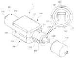
이하, 본 발명의 기본 구성의 실시 예로서, 제1 실시 예에 따른 퓨즈 타입의 조명등용 전구의 각부 구성을 도 1 내지 도 3을 참고로 구체적으로 설명한다. 도 1은 제1 실시 예에 따른 전구의 사시도, 도 2는 제1 실시 예에 따른 분해 사시도, 도 3은 제1 실시 예에 따른 전구의 측단면도이다.Hereinafter, as a preferred embodiment of the basic configuration of the present invention, the configuration of each part of the fuse-type light bulb according to the first embodiment will be described in detail with reference to FIG. 1 to FIG. FIG. 1 is a perspective view of a bulb according to the first embodiment, FIG. 2 is an exploded perspective view according to the first embodiment, and FIG. 3 is a side sectional view of the bulb according to the first embodiment.
먼저, 상기 베이스(100)는;First, the
내부로 일면이 개방된 공간을 갖고, 양측에 제1끼움부(120)가 각각 돌출 형성되며, 완성된 전구(1)의 케이스가 되는 것이다.And a first fitting
이와 같은 베이스(100)는 기판(200) 및 렌즈(300)를 흔들림 없이 견고하게 고정하면서, 외부 충격에 의해 파손되지 않도록 내구성이 우수하면서, 기판(200)의 LED소자(210)에서 발생하는 열기에 변형되지 않는 성질의 합성수지 재질로 제작되며, 표면으로 부식 방지를 위한 표면처리를 수행할 수 있다.The
본 발명의 기본 실시 예에 따른 베이스(100)는; 베이스 몸체(110), 제1끼움부(120), 냉각홀(112)을 더 포함하여 구성할 수 있다.The
예를 들면, 상기 베이스(100)는; 내부로 일면이 개방된 공간을 갖는 베이스 몸체(110)를 더 포함한다.For example, the
상기 베이스 몸체(110)는 일면이 개방되면서 내부에 공간을 갖는 사각 함체 형태로 형성되는 구조이다. 상기 베이스 몸체(110)는 개방 측이 기판(200)을 사이에 두고 렌즈 몸체(310)의 개방 측과 서로 조립됨으로, 베이스(100)가 렌즈(300)에 조립가능하게 한다.The
또한, 상기 베이스(100)는; 베이스 몸체(110)의 양측단에 각각 돌출되는 제1끼움부(120)를 더 포함한다.Also, the
상기 제1끼움부(120)는 베이스 몸체(110)의 성형 과정에서 상기 베이스 몸체(110)의 양측단에 일체로 돌출되어 형성되는 것이며, 상기 베이스 몸체(110)의 양측단에 반원형으로 각각 돌출되는데, 그 반원의 크기는 후술하는 터미널(400)의 크기에 대응되는 구조이다.The first fitting
또한, 상기 베이스(100)는; 후면에 하나 또는 그 이상으로 관통 형성되어 상기 기판(200)의 LED소자(210)에서 발생하는 열기를 외기와 통풍하여 냉각되게 하는 냉각홀(112)을 더 포함한다.Also, the
상기 냉각홀(112)은 베이스 몸체(110)의 후면 판에 하나 또는 그 이상으로 관통되는 구멍이며, 완성된 전구(1)는 베이스(100)의 내부 공간이 밀폐되는데, 상기 냉각홀(112)을 베이스 몸체(110)에 형성함으로 외기와 통하게 하여 기판(200)의 LED소자(210)에서 발생하는 열기가 통풍작용에 의해 냉각될 수 있게 한다.
The cooling hole 112 is one or more holes penetrating through the rear plate of the
그리고, 상기 기판(200)은;The
상기 베이스(100)의 개방된 면을 덮으며, 노출된 일면에 LED소자(210)가 구비되며, 완성된 전구(1)에서 광원 기능을 하는 것이다.An
이와 같은 기판(200)은 인쇄회로기판에 LED소자(210)와 더불어, LED소자(210)의 제어, 전기공급 등을 위한 각종 전자부품들이 마련된 것이며, 상기 기판(200)의 양단에는 후술하는 터미널(400)에 끼워지면서 납땜으로 전기접속되는 단자(220)가 각각 형성되고, 상기 기판(200)은 상기 베이스(100)의 개방된 면과 동일한 외형으로 제작되는데, 상기 기판(200)의 내측으로 후술하는 체결 돌기(111,311)가 삽입되는 다수의 고정 구멍(230)이 형성되는 구조이다.Such a
이때, 상기 LED소자(210)는 발광다이오드(LED:light emitting diode)이며, 전구(1)의 설치 장소 및 사용자의 선택에 따라 하나 또는 복수로 기판(200)에 구비하고, 그 발광 색 역시 다양하게 적용가능한 것이다.
At this time, the
그리고, 상기 렌즈(300)는;The
상기 기판(200)의 노출된 면을 덮어서 상기 LED소자(210)의 빛을 외부로 발산시키며, 양측에 제2끼움부(320)가 각각 돌출 형성되고, 상기 기판(200)을 베이스(100)에 밀착시켜 결합하면서 LED소자(210)를 외부 환경으로부터 보호하기 위한 것이다.A second fitting
이와 같은 렌즈(300)는 외부 충격에 의해 파손되지 않으며 기판(200)의 LED소자(210)를 보호할 수 있도록 내구성이 우수하면서, 기판(200)의 LED소자(210)에서 발생하는 열기에 변형되지 않는 성질의 합성수지 재질로 제작되며, 표면으로 부식 방지를 위한 표면처리를 수행할 수 있다.Such a
본 발명의 기본 실시 예에 따른 렌즈(300)는; 렌즈 몸체(310), 제2끼움부(320)를 더 포함하여 구성할 수 있다.The
예를 들면, 상기 렌즈(300)는; 내부로 일면이 개방된 공간에 상기 기판(200)의 LED소자(210)가 수용되면서 차폐하는 렌즈 몸체(310)를 더 포함한다.For example, the
상기 렌즈 몸체(310)는 일면이 개방되면서 내부에 공간을 갖는 사각 함체 형태로 형성되되, 상기 베이스 몸체(110)의 크기와 동일하게 제작되는 구조이다. 상기 렌즈 몸체(310)는 개방 측이 기판(200)을 사이에 두고 베이스 몸체(110)의 개방 측과 서로 조립된다.The
또한, 상기 렌즈(300)는; 렌즈 몸체(310)의 양측단에 각각 돌출되는 제2끼움부(320)를 더 포함한다.Also, the
상기 제2끼움부(320)는 렌즈 몸체(310)의 성형 과정에서 상기 렌즈 몸체(310)의 양측단에 일체로 돌출되어 형성되는 것이며, 상기 렌즈 몸체(310)의 양측단에 반원형으로 각각 돌출되는데, 그 반원의 크기는 후술하는 터미널(400)의 크기에 대응되는 구조이다.The second
여기서 상기 렌즈(300)와 베이스(100)가 기판(200)을 사이에 두고 서로 결합되면, 상기 제1,2끼움부(120,320)는 서로 대향되면서 터미널(400)이 끼워질 수 있도록 원기둥 형상을 갖게 된다.
When the
이와 더불어, 본 발명의 기본 실시 예에 따른 베이스(100) 및 렌즈(300)는; 체결 돌기(111,311)를 더 포함하여 구성할 수 있다.In addition, the
예컨대, 상기 베이스(100) 및 렌즈(300)는, 일면에 돌출형성되되, 그 돌출된 부분에 상기 기판(200)이 끼워지면서 고정되게 하는 체결 돌기(111,311)를 더 포함한다.For example, the
상기 체결 돌기(111,311)는 상기 베이스 몸체(110) 및 렌즈 몸체(310)의 개방된 일면의 각 모서리에 원기둥 형태로 각각 돌출형성되는 구조이다.The fastening protrusions 111 and 311 are protruded from the
이때, 상기 체결 돌기(111,311)는 상기 기판(200)에 형성된 고정 구멍(230)에 끼워짐으로 상기 기판(200)이 베이스(100)와 렌즈(300) 사이에서 정확한 위치로 고정결합될 수 있게 되어, 기판(200)을 접착제 등으로 고정하지 않고 단순 끼움 결합으로 간편하게 조립할 수 있다.
The fastening protrusions 111 and 311 are fitted in the fixing holes 230 formed in the
그리고, 상기 한 쌍의 터미널(400)은;The pair of
상기 제1,2끼움부(120,320)의 외주에 각각 끼워져 고정되되, 상기 기판(200)에 전기접속되면서 외부 전원을 기판(200)에 공급하기 위한 것이다.The first and second
이와 같은 터미널(400)은 조명등의 전원이 공급될 수 있도록 전기 전도성이 우수하고 외부 충격에 쉽게 변형되지 않는 내구성이 좋은 금속 재질로 제작되며, 표면으로 부식 방지를 위한 표면처리를 수행할 수 있다.Such a terminal 400 is made of a metal material having good electrical conductivity and durable against external impact so as to be able to be supplied with power of a lamp or the like, and can be subjected to a surface treatment for preventing corrosion on the surface thereof.
이때, 상기 터미널(400)은 일면으로 상기 제1,2끼움부(120,320)가 끼워질 수 있도록 개방된 원통체 구조를 갖으며, 상기 터미널(400)의 막힌 측면으로 단자 구멍(410)이 관통 형성됨으로 상기 기판(200)의 단자(220)가 상기 단자 구멍(410)으로 끼워질 수 있게 한다.At this time, the terminal 400 has a cylindrical structure that is opened to allow the first and second
상기 단자 구멍(410)으로 기판(200)의 단자(220)가 끼워지면 납땜으로 단자(220)를 터미널(400)에 고정하여 터미널(400)을 통해 공급되는 전기가 상기 단자(220)를 통해 기판(200)으로 흐를 수 있게 한다.
When the
그리고, 상기 굴절부(500)는;The refracting
상기 렌즈(300)의 안쪽에서 복수의 원형 돌기(510)가 동일 중심으로 확장되게 형성되어, 상기 원형 돌기(510)를 이용해 상기 LED소자(210)의 빛을 다방향으로 굴절시켜 산란하기 위한 것이다.A plurality of
이와 같은 굴절부(500)는 기판(200)의 LED소자(210)에서 발생하는 열기에 변형되지 않는 합성수지 재질로 형성되며, 상기 렌즈(300)의 안쪽에 일체로 형성하거나, 또는 굴절부(500)를 별도 제작한 후 렌즈(300)에 부착하여 사용할 수 있다.The refracting
이때, 상기 원형 돌기(510)는 원형 링 형태로 렌즈(300)의 안쪽 중심부에서부터 복수의 원형 돌기(510)가 동일 중심으로 확장되어 형성되면서 굴절부(500)로 이루어지게 된다.At this time, the
이와 더불어, 본 발명의 기본 실시 예에 따른 원형 돌기(510)는; 전방 굴절면(511), 측방 굴절면(512)을 더 포함하여 구성할 수 있다.In addition, the
예컨대, 상기 원형 돌기(510)는; 안쪽으로 완만한 경사각을 갖으면서 마련되는 전방 굴절면(511) 및, 상기 전방 굴절면(511)의 둘레에 급한 경사각을 갖으면서 마련되는 측방 굴절면(512)을 더 포함한다.For example, the
상기 전방 굴절면(511)은, 원형 링 형상의 원형 돌기(510) 안쪽으로 완만한 경사각을 갖도록 라운드 면으로 형성되는데, 그 전방 굴절면(511)의 경사각은 30°로 형성됨이 바람직한 것이다.The front refracting
상기 측방 굴절면(512)은, 원형 링 형상의 원형 돌기(510) 측방 둘레로 급한 경사각을 갖도록 라운드 면으로 형성되는데, 그 측방 굴절면(512)의 경사각은 80°로 형성됨이 바람직한 것이다.The lateral refracting
이때, 상기 전방 굴절면(511)은 기판(200)의 LED소자(210)로부터 조사되는 빛을 전방향으로 굴절시키고, 상기 측방 굴절면(512)은 기판(200)의 LED소자(210)로부터 조사되는 빛을 측방향으로 굴절시킴에 따라 복수의 원형 돌기(510)를 갖는 굴절부(500)가 LED소자(210)의 빛을 산란시키도록 한다.At this time, the front refracting
따라서 본 발명은 굴절부(500)의 구조가 부가됨에 따라 LED소자(210)의 광량이 많은 것을 사용하여도 빛을 산란할 수 있어 자동차의 실내 및 화장대와 같은 가구에서 은은한 분위기의 빛이 필요한 대상에 적합하고, LED소자(210)의 광량을 낮추는 전기 부품들이 필요 없어 제조 비용이 절감되게 된다.
Therefore, according to the present invention, since the structure of the refracting
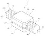
한편, 본 발명의 다른 구성의 실시 예로서, 제2 실시 예에 따른 퓨즈 타입의 조명등용 전구에 대한 각부 구성을 도 4를 참고로 구체적으로 설명한다.As another embodiment of the present invention, the configuration of each part of a fuse-type light bulb according to the second embodiment will be described in detail with reference to FIG.
이에 따르면, 전술한 구조로 이루어진 전구(1)는, 상기 제1,2끼움부(120,320)의 둘레에 등간격으로 가압돌기(121,321)가 길이방향으로 돌출형성되는 것을 더 포함하며,According to the structure, the
상기 제1,2끼움부(120,320)에 터미널(300)이 결합되는 과정에서, 상기 가압돌기(121,321)에 터미널(400)의 내부 측면이 여유 없이 밀착되면서 억지 끼움으로 터미널(400)이 고정되는 것을 더 포함한다.The inner surface of the terminal 400 is closely contacted to the
이때, 상기 가압돌기(121,321)는 제1,2끼움부(120,320)의 둘레에 등간격으로 형성되는데, 바람직하게는 3개 ~ 4개가 형성되어 터미널(300)의 내부 측면을 균등하게 지지할 수 있게 한다.At this time, the
상기 가압돌기(121,321)는 삼각 돌기 형태로 그 외측 모서리 부분이 터미널(300)의 내부 측면에 압박되면서 억지 끼움이 유발되게 한다.The
따라서 본 발명은 가압돌기(121,321)가 적용됨에 따라 터미널(300)의 조립과정이 단순하고, 별도로 터미널(300)의 결합 부분을 접착하는 공정이 필요하지 않아 제조시간 및 제조 단가를 낮출 수 있게 된다.
Therefore, according to the present invention, since the
한편, 본 발명의 또 다른 구성의 실시 예로서, 제3 실시 예에 따른 퓨즈 타입의 조명등용 전구에 대한 각부 구성을 도 5를 참고로 구체적으로 설명한다.As another embodiment of the present invention, the configuration of each part of a fuse-type light bulb according to the third embodiment will be described in detail with reference to FIG.
이에 따르면, 전술한 구조로 이루어진 전구(1) 중 상기 굴절부(500)는; 측방 굴절면(512)에 형성되며, 상기 LED소자(210)의 빛을 반사시키는 반사층(513)을 더 포함한다.According to this, among the
상기 반사층(513)은 반사 재질의 양면을 갖는 띠 형상의 필름으로 제작되며, 상기 측방 굴절면(512)의 폭에 대응되어 상기 측방 굴절면()에 반사층(513)이 접착 테이프 형태로 부착되는 구조이다.The
이때, 상기 반사층(513)은 전구(1)를 적용하는 대상에 따라 빛의 밝기를 조절하기 위해 상기 굴절부(500)에 전체적으로 형성시켜 빛의 밝기를 높게 하거나, 또는 그 수를 조절하여 빛의 밝기를 낮추게 된다.At this time, the
따라서 본 발명은 반사층(513)이 적용됨에 따라 LED소자(210)의 빛을 반사층(513)을 이용해 반사시켜 증폭할 수 있으며, 빛의 밝기가 약한 경우 반사층(513)의 수를 증가시켜 빛의 밝기를 간편하게 임의 조절할 수 있게 된다.
Therefore, according to the present invention, when the
한편, 본 발명의 또 다른 구성의 실시 예로서, 제4 실시 예에 따른 퓨즈 타입의 조명등용 전구에 대한 각부 구성을 도 6을 참고로 구체적으로 설명한다.As another embodiment of the present invention, the structure of each part of a fuse-type light bulb according to the fourth embodiment will be described in detail with reference to FIG.
이에 따르면, 전술한 구조로 이루어진 전구(1) 중 상기 터미널(400)은; 외주에 등간격으로 돌출형성되어 터미널(400)이 결합되는 면에 마찰력을 상승시키는 다수의 고정 요철(420)을 더 포함한다.According to this, among the
상기 고정 요철(420)은 터미널(400)의 외주에 다수의 요철(凹凸)이 등간격으로 형성되어 이루어진 것이며, 상기 고정 요철(420)이 조명등의 설치 장소에 직접 접촉되면서 마찰력이 상승하게 하여 외부 진동 및 충격에 의해 조명등에 설치된 전구(1)가 쉽게 움직이지 않도록 한다.The fixed concavity and
따라서 본 발명은 고정 요철(420)의 구조가 부가됨에 따라 외부 진동 및 충격에 의한 움직임에도 터미널()이 조명등의 설치 장소에 움직임 없이 고정되어 조명등용 전구()가 쉽게 회전되지 않아 빛의 조사 방향이 제멋대로 바뀌는 것을 방지하게 된다.
Accordingly, since the structure of the fixed
한편, 본 발명의 또 다른 구성의 실시 예로서, 제5 실시 예에 따른 퓨즈 타입의 조명등용 전구에 대한 각부 구성을 도 7을 참고로 구체적으로 설명한다.As another embodiment of the present invention, the configuration of each part of a fuse-type light bulb according to the fifth embodiment will be described in detail with reference to FIG.
이에 따르면, 전술한 구조로 이루어진 전구(1) 중 상기 베이스(100)는, 베이스몸체(110)의 일면 중앙에 일체로 막대 형태로 돌출되어 전구(1)가 조명등의 소켓에 설치되면 전구(1)를 지지하여 제자리 회전하지 않게 고정하는 지지부(115)를 더 포함한다.The
상기 지지부(115)는 베이스몸체(110)의 일면 중앙에서 일체로 막대 형태로 전구(1)의 길이방향으로 돌출되어 형성되는 것이며, 본 발명의 전구(1)가 터미널(400)을 이용해 조명등의 소켓에 끼워지면, 상기 터미널(400)의 외형적(원통) 특성에 의해 전구(1)가 소켓에서 의도치 않게 회전할 수 있음에 따라 상기 지지부(115)가 조명등의 소켓이 마련된 안쪽에 직접 지지되는 작용으로 전구(1)가 제자리 회전하지 않게 고정하는 구조이다.
The
이상 설명한 바와 같이. 본 발명은 특정의 바람직한 실시 예를 예시한 설명과 도면으로 표현하였으나, 여기서 사용하는 용어들은 본 발명을 용이하게 설명하기 위함이며, 이 용어들에 대한 의미 한정이나, 특허청구범위에 기재된 범위를 제한하기 위함이 아니며,As described above. While the present invention has been particularly shown and described with reference to certain preferred embodiments thereof, it is to be understood that the terminology used herein is for the purpose of describing the present invention only and is not intended to limit the scope of the claims. But is not intended to,
본 발명은 상기한 실시 예에 따른 특허청구범위에 의해 나타난 발명의 사상 및 영역을 벗어나지 않는 범위 내에서 당해 발명이 속하는 기술 분야에서 통상의 지식을 가진 자에 의해 다양한 변경 및 개조, 수정 등이 가능할 수 있음을 누구나 쉽게 알 수 있을 것이다.It will be understood by those skilled in the art that various changes in form and details may be made therein without departing from the spirit and scope of the invention as defined by the appended claims. It will be easy for anyone to know.
1; 전구 100; 베이스
110; 베이스 몸체 120; 제1끼움부
200; 기판 210; LED소자
220; 단자 230; 고정 구멍
300; 렌즈 310; 렌즈 몸체
320; 제2끼움부 400; 터미널
500; 굴절부 510; 원형 돌기One;
110; A
200; A
220; Terminal 230; Fixing hole
300; A
320; Second
500;
Claims (4)
Translated fromKorean내부로 일면이 개방된 공간을 갖고, 양측에 제1끼움부(120)가 각각 돌출 형성된 베이스(100)와;
상기 베이스(100)의 개방된 면을 덮으며, 노출된 일면에 LED소자(210)가 구비된 기판(200)과;
상기 기판(200)의 노출된 면을 덮어서 상기 LED소자(210)의 빛을 외부로 발산시키며, 양측에 제2끼움부(320)가 각각 돌출 형성된 렌즈(300)와;
상기 제1,2끼움부(120,320)의 외주에 각각 끼워져 고정되되, 상기 기판(200)에 전기접속되면서 외부 전원을 기판(200)에 공급하는 한 쌍의 터미널(400) 및,
상기 렌즈(300)의 안쪽에서 복수의 원형 돌기(510)가 동일 중심으로 확장되게 형성되어, 상기 원형 돌기(510)를 이용해 상기 LED소자(210)의 빛을 다방향으로 굴절시켜 산란하는 굴절부(500)를 포함하여 구성되고,
상기 원형 돌기(510)는, 안쪽으로 완만한 경사각을 갖으면서 마련되는 전방 굴절면(511) 및, 상기 전방 굴절면(511)의 둘레에 급한 경사각을 갖으면서 마련되는 측방 굴절면(512)을 더 포함하며,
상기 베이스(100) 및 렌즈(300)는, 일면에 돌출형성되되, 그 돌출된 부분에 상기 기판(200)이 끼워지면서 고정되게 하는 체결 돌기(111,311)를 더 포함하고,
상기 베이스(100)는, 후면에 하나 또는 그 이상으로 관통 형성되어 상기 기판(200)의 LED소자(210)에서 발생하는 열기를 외기와 통풍하여 냉각되게 하는 냉각홀(112)을 더 포함하며,
상기 제1,2끼움부(120,320)의 둘레에 등간격으로 가압돌기(121,321)가 길이방향으로 돌출형성되는데, 상기 가압돌기(121,321)는 삼각 돌기 형태로 그 외측 모서리 부분이 터미널(300)의 내부 측면에 압박되면서 억지 끼움이 유지됨으로, 상기 제1,2끼움부(120,320)에 터미널(300)이 결합되는 과정에서 상기 가압돌기(121,321)에 터미널(400)의 내부 측면이 여유 없이 밀착되면서 억지 끼워져 터미널(400)이 고정되는 것을 더 포함하고,
상기 베이스(100)는, 기판(200)을 사이에 두고 렌즈(300)에 조립가능하게 하는 베이스 몸체(110)의 일면 중앙에 일체로 막대 형태로 돌출되어 전구(1)가 조명등의 소켓에 설치되면 전구(1)를 지지하여 제자리 회전하지 않게 고정하는 지지부(115)를 더 포함하는 퓨즈 타입의 조명등용 전구.As a light bulb,
A base 100 having a space open at one side thereof and having first fitting portions 120 protruding from both sides thereof;
A substrate 200 covering the open side of the base 100 and having an exposed LED element 210;
A lens 300 that covers the exposed surface of the substrate 200 and emits light of the LED device 210 to the outside and has second fitting parts 320 protruded on both sides thereof;
A pair of terminals 400 fixedly fitted on the outer periphery of the first and second fitting parts 120 and 320 and supplying external power to the substrate 200 while being electrically connected to the substrate 200,
A plurality of circular protrusions 510 are formed to extend from the inside of the lens 300 to the same center so that the circular protrusions 510 are used to refract the light of the LED element 210 in various directions, (500)
The circular protrusion 510 further includes a front refracting surface 511 provided with a gentle inclination angle inward and a lateral refracting surface 512 provided with a sharp inclination angle around the front refracting surface 511 ,
The base 100 and the lens 300 may further include protrusions formed on one surface thereof and fastening protrusions 111 and 311 for fixing the substrate 200 while being sandwiched between the protrusions 111 and 311,
The base 100 may further include a cooling hole 112 formed at one or more surfaces thereof to penetrate the base 100 to cool the LED element 210 of the substrate 200 by ventilating the ambient air,
The pressing protrusions 121 and 321 are protruded in the longitudinal direction at equal intervals around the first and second fitting parts 120 and 320. The pressing protrusions 121 and 321 are formed in the shape of triangular protrusions, The inner side surface of the terminal 400 is closely contacted with the pressing protrusions 121 and 321 while the terminal 300 is coupled to the first and second fitting portions 120 and 320, Further comprising that the terminal (400) is securely clamped,
The base 100 integrally protrudes in the form of a rod at the center of one side of a base body 110 which can be assembled to the lens 300 with the substrate 200 interposed therebetween so that the bulb 1 is installed in the socket of the illumination lamp Further comprising a support part (115) for supporting the bulb (1) so as not to rotate in place.
Priority Applications (1)
| Application Number | Priority Date | Filing Date | Title |
|---|---|---|---|
| KR1020160092544AKR101746032B1 (en) | 2016-07-21 | 2016-07-21 | The Fuse Type Lamp |
Applications Claiming Priority (1)
| Application Number | Priority Date | Filing Date | Title |
|---|---|---|---|
| KR1020160092544AKR101746032B1 (en) | 2016-07-21 | 2016-07-21 | The Fuse Type Lamp |
Publications (1)
| Publication Number | Publication Date |
|---|---|
| KR101746032B1true KR101746032B1 (en) | 2017-06-12 |
Family
ID=59219620
Family Applications (1)
| Application Number | Title | Priority Date | Filing Date |
|---|---|---|---|
| KR1020160092544AActiveKR101746032B1 (en) | 2016-07-21 | 2016-07-21 | The Fuse Type Lamp |
Country Status (1)
| Country | Link |
|---|---|
| KR (1) | KR101746032B1 (en) |
Cited By (2)
| Publication number | Priority date | Publication date | Assignee | Title |
|---|---|---|---|---|
| KR101865209B1 (en)* | 2017-11-21 | 2018-06-07 | 주식회사 삼원파워텍 | The Fuse Type Lamp |
| KR102484379B1 (en)* | 2022-08-16 | 2023-01-03 | 주식회사 하스인더스트리 | Led lamp for automobile courtesy light |
Citations (2)
| Publication number | Priority date | Publication date | Assignee | Title |
|---|---|---|---|---|
| JP2012004095A (en)* | 2010-05-18 | 2012-01-05 | Enplas Corp | Luminous flux control member, light emitting device, and lighting device |
| JP2016508283A (en)* | 2012-12-27 | 2016-03-17 | チャン,ヨガン | Fuse type automotive lighting |
- 2016
- 2016-07-21KRKR1020160092544Apatent/KR101746032B1/enactiveActive
Patent Citations (2)
| Publication number | Priority date | Publication date | Assignee | Title |
|---|---|---|---|---|
| JP2012004095A (en)* | 2010-05-18 | 2012-01-05 | Enplas Corp | Luminous flux control member, light emitting device, and lighting device |
| JP2016508283A (en)* | 2012-12-27 | 2016-03-17 | チャン,ヨガン | Fuse type automotive lighting |
Cited By (2)
| Publication number | Priority date | Publication date | Assignee | Title |
|---|---|---|---|---|
| KR101865209B1 (en)* | 2017-11-21 | 2018-06-07 | 주식회사 삼원파워텍 | The Fuse Type Lamp |
| KR102484379B1 (en)* | 2022-08-16 | 2023-01-03 | 주식회사 하스인더스트리 | Led lamp for automobile courtesy light |
Similar Documents
| Publication | Publication Date | Title |
|---|---|---|
| CN101687472B (en) | Lighting assembly with cooling shroud | |
| US8882295B2 (en) | Lamp device and luminaire | |
| EP2503234A2 (en) | Lamp device and luminaire | |
| US20130027928A1 (en) | Lighting apparatus | |
| JP4135485B2 (en) | Light emitting diode light source and light emitting diode lighting fixture | |
| US8803409B1 (en) | Lamp device, light-emitting device and luminaire | |
| JP2010055993A (en) | Lighting system and luminaire | |
| JP6173476B2 (en) | Lighting device including an improved heat transfer device | |
| TWI509193B (en) | Luminaire | |
| JP2010192337A (en) | Lamp system and lighting apparatus | |
| CN102022699A (en) | Light emitting module and vehicle lamp | |
| KR101746032B1 (en) | The Fuse Type Lamp | |
| JP3163443U (en) | LED lighting device | |
| JP2013069441A (en) | Bulb type lighting device | |
| KR20100100450A (en) | Led fluorescent lamp | |
| CN204227103U (en) | Lamp device and lighting device | |
| JP2013008582A (en) | Lamp device | |
| KR20170025132A (en) | Light diffusion sheet for interior of optically transmissive pipe and led illumination device of fluorescent type including the same | |
| JP2010262780A (en) | Lamp apparatus and lighting apparatus | |
| KR101865209B1 (en) | The Fuse Type Lamp | |
| JP2021106078A (en) | Vehicular illuminating device, vehicular illuminating device set, and vehicular lighting fixture | |
| JP6696366B2 (en) | lamp | |
| JP6566347B2 (en) | Lighting device | |
| CN219550355U (en) | Lighting lamp and vehicle | |
| KR102511805B1 (en) | LED lamp for vehicle |
Legal Events
| Date | Code | Title | Description |
|---|---|---|---|
| PA0109 | Patent application | Patent event code:PA01091R01D Comment text:Patent Application Patent event date:20160721 | |
| PA0201 | Request for examination | ||
| PA0302 | Request for accelerated examination | Patent event date:20160728 Patent event code:PA03022R01D Comment text:Request for Accelerated Examination Patent event date:20160721 Patent event code:PA03021R01I Comment text:Patent Application | |
| PE0902 | Notice of grounds for rejection | Comment text:Notification of reason for refusal Patent event date:20160928 Patent event code:PE09021S01D | |
| PE0902 | Notice of grounds for rejection | Comment text:Final Notice of Reason for Refusal Patent event date:20170124 Patent event code:PE09021S02D | |
| E701 | Decision to grant or registration of patent right | ||
| PE0701 | Decision of registration | Patent event code:PE07011S01D Comment text:Decision to Grant Registration Patent event date:20170518 | |
| GRNT | Written decision to grant | ||
| PR0701 | Registration of establishment | Comment text:Registration of Establishment Patent event date:20170605 Patent event code:PR07011E01D | |
| PR1002 | Payment of registration fee | Payment date:20170605 End annual number:3 Start annual number:1 | |
| PG1601 | Publication of registration | ||
| PR1001 | Payment of annual fee | Payment date:20200427 Start annual number:4 End annual number:4 | |
| PR1001 | Payment of annual fee | Payment date:20210426 Start annual number:5 End annual number:5 | |
| PR1001 | Payment of annual fee | Payment date:20220510 Start annual number:6 End annual number:6 | |
| PR1001 | Payment of annual fee | Payment date:20230509 Start annual number:7 End annual number:7 | |
| PR1001 | Payment of annual fee | Payment date:20240527 Start annual number:8 End annual number:8 | |
| PR1001 | Payment of annual fee | Payment date:20250512 Start annual number:9 End annual number:9 |