KR101744571B1 - A smart door-lock - Google Patents
A smart door-lockDownload PDFInfo
- Publication number
- KR101744571B1 KR101744571B1KR1020150082818AKR20150082818AKR101744571B1KR 101744571 B1KR101744571 B1KR 101744571B1KR 1020150082818 AKR1020150082818 AKR 1020150082818AKR 20150082818 AKR20150082818 AKR 20150082818AKR 101744571 B1KR101744571 B1KR 101744571B1
- Authority
- KR
- South Korea
- Prior art keywords
- terminal
- door lock
- unit
- relay server
- door
- Prior art date
- Legal status (The legal status is an assumption and is not a legal conclusion. Google has not performed a legal analysis and makes no representation as to the accuracy of the status listed.)
- Active
Links
Images


Classifications
- E—FIXED CONSTRUCTIONS
- E05—LOCKS; KEYS; WINDOW OR DOOR FITTINGS; SAFES
- E05B—LOCKS; ACCESSORIES THEREFOR; HANDCUFFS
- E05B47/00—Operating or controlling locks or other fastening devices by electric or magnetic means
- H—ELECTRICITY
- H04—ELECTRIC COMMUNICATION TECHNIQUE
- H04B—TRANSMISSION
- H04B1/00—Details of transmission systems, not covered by a single one of groups H04B3/00 - H04B13/00; Details of transmission systems not characterised by the medium used for transmission
- H04B1/38—Transceivers, i.e. devices in which transmitter and receiver form a structural unit and in which at least one part is used for functions of transmitting and receiving
- H—ELECTRICITY
- H04—ELECTRIC COMMUNICATION TECHNIQUE
- H04Q—SELECTING
- H04Q9/00—Arrangements in telecontrol or telemetry systems for selectively calling a substation from a main station, in which substation desired apparatus is selected for applying a control signal thereto or for obtaining measured values therefrom
- H—ELECTRICITY
- H04—ELECTRIC COMMUNICATION TECHNIQUE
- H04W—WIRELESS COMMUNICATION NETWORKS
- H04W12/00—Security arrangements; Authentication; Protecting privacy or anonymity
- H04W12/06—Authentication
- E—FIXED CONSTRUCTIONS
- E05—LOCKS; KEYS; WINDOW OR DOOR FITTINGS; SAFES
- E05B—LOCKS; ACCESSORIES THEREFOR; HANDCUFFS
- E05B47/00—Operating or controlling locks or other fastening devices by electric or magnetic means
- E05B2047/0048—Circuits, feeding, monitoring
- E05B2047/0071—Connecting lockparts by electronic communication means only, e.g. bus systems, time multiplexing
- E—FIXED CONSTRUCTIONS
- E05—LOCKS; KEYS; WINDOW OR DOOR FITTINGS; SAFES
- E05B—LOCKS; ACCESSORIES THEREFOR; HANDCUFFS
- E05B47/00—Operating or controlling locks or other fastening devices by electric or magnetic means
- E05B2047/0094—Mechanical aspects of remotely controlled locks
- E05B2047/0095—Mechanical aspects of locks controlled by telephone signals, e.g. by mobile phones
Landscapes
- Engineering & Computer Science (AREA)
- Computer Networks & Wireless Communication (AREA)
- Signal Processing (AREA)
- Computer Security & Cryptography (AREA)
- Lock And Its Accessories (AREA)
Abstract
Translated fromKoreanDescription
Translated fromKorean본 발명은 휴대용 단말기 및 중계 서버를 이용하고, 사용자가 원거리에서 도어록을 잠금 또는 해제하는 스마트 도어록에 관한 것이다.
The present invention relates to a smart door lock which uses a portable terminal and a relay server and which allows a user to lock or unlock a door lock at a remote location.
도어의 잠금 또는 해제를 위해 사용되는 도어록 장치는 자물쇠와 열쇠를 기본적 구성으로 한다. 종래에는 자물쇠 및 열쇠의 기계적 구동을 통해서 도어가 잠금 또는 해제되는 기계식 도어록 장치들이 사용되어 왔지만, 최근에는 사용자가 입력한 전자 신호에 의해 잠기거나 열리는 디지털 도어록 장치가 보편적으로 사용되고 있다.The door lock device used for locking or unlocking the door has a basic structure of a lock and a key. 2. Description of the Related Art [0002] In the past, mechanical door lock devices have been used in which doors are locked or unlocked through mechanical operation of locks and keys. Recently, however, digital door lock devices that are locked or opened by electronic signals input by a user are commonly used.
한국 공개특허 특2001-0056007호에는 휴대용 무선 단말기 고유 정보를 이용한 도어록 장치 및 제어 방법이 개시되고 있다.Korean Patent Laid-Open No. 2001-0056007 discloses a door lock device and a control method using portable wireless terminal specific information.
하지만, 한국 공개특허 특2001-0056007호에 개시된 도어록 장치에 따르면, 도어록과 휴대용 무선 단말기가 근접거리에 있어야 하며, 원거리에서의 도어 잠금 및 해제는 어렵다.
However, according to the door lock device disclosed in Korean Patent Laid-Open Publication No. 2001-0056007, the door lock and the portable wireless terminal must be close to each other, and it is difficult to lock and unlock the door at a long distance.
본 발명은 휴대용 단말기 및 중계 서버를 이용하고, 사용자가 원거리에서 도어록을 잠금 또는 해제하는 스마트 도어록에 관한 것이다.The present invention relates to a smart door lock which uses a portable terminal and a relay server and which allows a user to lock or unlock a door lock at a remote location.
본 발명의 이루고자 하는 기술적 과제들은 이상에서 언급한 기술적 과제들로 제한되지 않으며, 언급하지 않은 또 다른 기술적 과제들은 아래의 기재로부터 본 발명이 속하는 기술분야에서 통상의 지식을 가진 자에게 명확하게 이해될 수 있을 것이다.
It is to be understood that both the foregoing general description and the following detailed description are exemplary and explanatory and are not to be construed as limiting the invention as defined by the appended claims and their equivalents. It will be possible.
본 발명의 스마트 도어록은 도어를 잠금 또는 해제하는 도어록 유니트와, 도어록 유니트의 잠금 또는 해제를 요청하는 단말기와, 도어록 유니트 및 단말기에 통신 연결되는 중계 서버 유니트를 포함할 수 있다.The smart door lock of the present invention may include a door lock unit for locking or unlocking a door, a terminal requesting locking or unlocking of the door lock unit, a door lock unit and a relay server unit communicatively connected to the terminal.
본 발명의 스마트 도어록은 적어도 하나 이상의 단말기의 단말기 식별 코드 및 적어도 하나 이상의 도어록 유니트의 도어록 식별 코드가 매칭되어 등록되는 중계 서버 유니트를 포함하고, 중계 서버 유니트는 단말기와 도어록 유니트를 통신 연결할 수 있다.
The smart door lock of the present invention includes a relay server unit in which a terminal identification code of at least one terminal and a door lock identification code of at least one door lock unit are matched and registered, and the relay server unit can communicate with the door lock unit.
본 발명의 스마트 도어록은 단말기와 도어록 유니트가 중계 서버 유니트를 통해서 통신 연결됨으로써, 사용자는 단말기를 통해 원거리에서 도어록 유니트의 잠금 또는 해제를 제어할 수 있다.In the smart door lock of the present invention, the terminal and the door lock unit are communicatively connected through the relay server unit, so that the user can control locking or unlocking of the door lock unit from a remote place through the terminal.
본 발명의 스마트 도어록은 중계 서버 유니트가 통신 노드가 됨으로써, 한 단말기가 복수의 도어록 유니트를 제어하거나 복수의 단말기가 하나의 도어록을 제어할 수 있다.In the smart door lock of the present invention, a relay server unit becomes a communication node, so that one terminal can control a plurality of door lock units or a plurality of terminals can control one door lock.
본 발명의 스마트 도어록은 중계 통신망을 이용함으로써, 원거리에서 도어락이 제어될 수 있다. 따라서 본 발명의 스마트 도어록은 1인이 다세대를 관리하는 경우나 다수가 공공 시설 등을 관리하는 경우 등과 같이 다양한 환경에 적용될 수 있다.
The smart door lock of the present invention can be controlled at a long distance by using the relay communication network. Therefore, the smart door lock of the present invention can be applied to various environments such as a case where one person manages multiple generations or a case where a majority manages public facilities.
도 1은 본 발명의 스마트 도어록을 나타내는 개념도이다.
도 2는 본 발명의 스마트 도어록을 구성하는 단말기와 도어록 유니트를 나타낸 블럭도이다.
도 3은 본 발명의 스마트 도어록을 구체적으로 나타낸 개략도이다.
도 4는 본 발명의 스마트 도어록의 동작을 나타낸 개략도이다.
도 5는 본 발명의 스마트 도어록의 다른 동작을 나타낸 개략도이다.
도 6은 도어록 유니트를 나타내는 정면도이다.
도 7은 다른 도어록 유니트를 나타내는 정면도이다.1 is a conceptual diagram showing a smart door lock of the present invention.
2 is a block diagram illustrating a terminal and a door lock unit constituting a smart door lock of the present invention.
FIG. 3 is a schematic view showing the smart door lock of the present invention in detail.
4 is a schematic diagram illustrating the operation of the smart door lock of the present invention.
5 is a schematic diagram illustrating another operation of the smart door lock of the present invention.
6 is a front view showing the door lock unit.
7 is a front view showing another door lock unit;
이하, 첨부된 도면들을 참조하여 본 발명에 따른 실시예를 상세히 설명한다. 이 과정에서 도면에 도시된 구성요소의 크기나 형상 등은 설명의 명료성과 편의상 과장되게 도시될 수 있다. 또한, 본 발명의 구성 및 작용을 고려하여 특별히 정의된 용어들은 사용자, 운용자의 의도 또는 관례에 따라 달라질 수 있다. 이러한 용어들에 대한 정의는 본 명세서 전반에 걸친 내용을 토대로 내려져야 한다.Hereinafter, embodiments of the present invention will be described in detail with reference to the accompanying drawings. The sizes and shapes of the components shown in the drawings may be exaggerated for clarity and convenience. In addition, terms defined in consideration of the configuration and operation of the present invention may be changed according to the intention or custom of the user, the operator. Definitions of these terms should be based on the content of this specification.
도 1은 본 발명의 스마트 도어록을 나타내는 개념도이다. 도 2는 본 발명의 스마트 도어록을 구성하는 단말기와 도어록 유니트를 나타낸 블럭도이다. 도 3은 본 발명의 스마트 도어록을 구체적으로 나타낸 개략도이다. 도 4는 본 발명의 스마트 도어록의 동작을 나타낸 개략도이다. 도 5는 본 발명의 스마트 도어록의 다른 동작을 나타낸 개략도이다. 도 6은 도어록 유니트를 나타내는 정면도이다. 도 7은 다른 도어록 유니트를 나타내는 정면도이다.1 is a conceptual diagram showing a smart door lock of the present invention. 2 is a block diagram illustrating a terminal and a door lock unit constituting a smart door lock of the present invention. FIG. 3 is a schematic view showing the smart door lock of the present invention in detail. 4 is a schematic diagram illustrating the operation of the smart door lock of the present invention. 5 is a schematic diagram illustrating another operation of the smart door lock of the present invention. 6 is a front view showing the door lock unit. 7 is a front view showing another door lock unit;
이하, 도 1 내지 도 7을 참조하여 본 발명의 스마트 도어록을 상세히 설명한다.Hereinafter, the smart door lock of the present invention will be described in detail with reference to FIGS. 1 to 7. FIG.
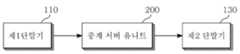
본 발명의 스마트 도어록은 도어를 잠금 또는 해제하는 도어록 유니트(300), 도어록 유니트(300)의 잠금 또는 해제를 요청하는 단말기(100), 도어록 유니트(300) 및 단말기(100)에 통신 연결되는 중계 서버 유니트(200)를 포함할 수 있다.The smart door lock of the present invention includes a
단말기(100)는 제1 단말기(110) 및 제2 단말기(130)를 포함할 수 있으며, 제1 단말기(110)는 도어록 유니트(300)의 소유주가 사용하는 단말기(100)가 될 수 있으며, 제2 단말기(130)는 제1 단말기(110)에 도어록 유니트(300)의 잠금 또는 해제의 요청이 필요한 사람의 단말기(100)가 될 수 있다. 제1 단말기(110)는 도어록 유니트(300)의 잠금 또는 해제 작동의 승인 권한, 전자키 부여 및 삭제 권한을 가질 수 있다.The
도어록 유니트(300)는 도어에 부착되어 도어를 직접적으로 잠금 또는 해제 가능한 기계적 장치일 수 있다.The
도어록 유니트(300)는 직접적으로 문자열 입력 또는 단말기(100)와 접촉인식 입력이 가능한 입력 패널부(310), 신호 처리 및 기계적 제어를 하는 제어부(330), 기계적 구동원인 액츄에이터부(350)를 포함할 수 있다.The
제어부(330)는 도어의 암호인 전자키를 확인하는 전자키 매칭부(331) 및 액츄에이터부(350)를 제어하는 액츄에이터 제어부(333)를 포함할 수 있다.The
단말기(100)는 사용자가 휴대하는 통신장치로, 스마트폰, 일반 휴대 전화기, 노트북, 테블릿 PC 등이 될 수 있다.The
중계 서버 유니트(200)는 통신망의 중심이 되고, 데이터의 저장 및 처리가 가능한 기기이다.The
본 발명의 스마트 도어록은 사용자가 원거리에서도 도어에 장착된 도어록 유니트(300)를 잠금 또는 해제하기 위한 기술이다. 단말기(100)와 도어록 유니트(300)가 중계 서버 유니트(200)를 통해서 통신 연결됨으로써, 사용자는 단말기(100)를 통해 원거리에서 도어록 유니트(300)의 잠금 또는 해제를 제어할 수 있다. 예를 들어, 예기치 않은 손님이나, 택배 배달 등으로 원거리에서 현관문의 개방이 필요할 시에 사용자가 집에 있지 않더라도 도어를 열어줄 수 있다. 다른 예로는 사용자가 깜박하고 집 현관문을 잠그지 않고 외출하였을 시에도 본 발명의 스마트 도어록을 사용하면 원거리에서 도어를 잠글 수 있다.The smart door lock of the present invention is a technique for locking or unlocking the
본 발명에서 단말기(100), 도어록 유니트(300), 중계 서버 유니트(200)에서 사용하는 통신은 인터넷 또는 전화망 등을 포함할 수 있다.In the present invention, the communication used in the
중계 서버 유니트(200)는 단말기(100)의 단말기 식별 코드 및 도어록 유니트(300)의 도어록 식별 코드가 등록될 수 있다. 단말기(100)와 도어록 유니트(300)가 전화망에서 중계 서버 유니트(200)에 등록될 경우, 단말기 식별 코드 및 도어록 식별 코드는 전화 번호 형식의 코드일 수 있다. 단말기(100)와 도어록 유니트(300)가 인터넷 망에서 중계 서버 유니트(200)에 등록될 경우, 단말기 식별 코드 및 도어록 식별 코드는 IP 주소 또는 임의로 사용자가 지정한 문자열일 수 있다.The
중계 서버 유니트(200)에 복수의 단말기(100) 또는 복수의 도어록 유니트(300)가 개별적으로 고유의 식별 코드로 등록됨으로써, 단말기(100) 또는 도어록 유니트(300) 간의 상호 인식 또는 통신연결에 혼선이 생기는 것을 방지할 수 있다.A plurality of
중계 서버에는 단말기 식별 코드와 도어록 식별 코드가 매칭되어 등록될 수 있다. 단말기 식별 코드와 도어록 식별 코드를 사전에 매칭시켜 둠으로써, 단말기(100)가 도어에 대한 잠금 또는 해제 명령을 중계 서버 유니트(200)에 전송할 시에 별도의 정보 입력 없이 해당 도어록 유니트(300)에 명령을 전달할 수 있다.The terminal identification code and the door lock identification code may be registered and registered in the relay server. When the
예를 들어, 사전 매칭이 없다면 사용자는 도어에 잠금 또는 해제를 요청할 때마다 해당 도어에 설치된 도어록 유니트(300)의 도어록 식별 코드를 추가로 입력해야한다. 하지만 본 발명의 스마트 도어록은 사전 매칭 기능을 통해서, 사용자가 단말기(100)를 통해 도어의 잠금 또는 해제 명령을 중계 서버 유니트(200)에 전송하면, 중계 서버 유니트(200)는 즉각적으로 사전에 매칭된 도어록 유니트(300)에 잠금 또는 해제 명령을 전달할 수 있다.For example, when there is no dictionary matching, the user must additionally input the door lock identification code of the
하나의 도어록 식별 코드에는 복수의 단말기 식별 코드가 매칭될 수 있다. 이에 따르면 복수의 사용자가 동일한 도어록 유니트(300)를 잠금거나 해제할 수 있다. 예들 들어, 한 세대 가족 구성원은 1인 이상일 수가 있고, 따라서 하나의 도어록 유니트(300)에 복수의 단말기(100)가 매칭될 필요가 있다.A plurality of terminal identification codes may be matched to one door lock identification code. Accordingly, a plurality of users can lock or unlock the same
단말기(100)가 도어에 대한 잠금 또는 해제 명령을 중계 서버 유니트(200)에 전송할 시, 중계 서버 유니트(200)는 단말기 식별 코드에 매칭된 상기 도어록 유니트(300)에 도어록 유니트(300)의 작동 코드가 되는 전자키를 송신할 수 있다.When the terminal 100 transmits a lock or unlock command for the door to the
전자키는 도어록 유니트(300)에 입력되는 문자열로, 도어록 유니트(300)가 잠금 또는 해제 작동을 하기 위한 최종 승인 암호이다. 구체적으로 전자키는 도어록 유니트(300)에 구비된 전자키 매칭부(331)에 입력되고, 전자키 매칭부(331)는 전자키가 도어의 잠금 또는 해제 권한이 있는 문자열인지를 확인할 수 있다. 확인결과가 권한이 있는 전자키로 판정되면 잠금 또는 해제 명령은 도어록 유니트(300)의 액츄에이터 제어부(333)로 전달되고, 액츄에이터 제어부(333)는 액츄에이터부(350)를 제어하여 도어를 잠금 또는 해제할 수 있다. 전자키는 중계 서버 유니트(200)로부터 전자키 매칭부(331)로 입력될 수도 있고, 중계 서버 유니트(200)를 거치지 않고 근거리 통신을 통해 단말기(100)로부터 입력될 수도 있다.The electronic key is a string input to the
근거리 통신을 통해 단말기(100)의 전자키를 도어록 유니트(300)에 입력할 경우, 단말기(100)는 보안 강화를 위해서 별도의 단말기 암호가 입력된 후에 전자키를 근거리 통신으로 도어록 유니트(300)에 전송할 수 있다. 단말기(100)를 분실할 경우에 단말기(100) 주인이 아닌 제3자가 단말기(100)를 습득하여 도어록 유니트(300)를 조작할 수 있다. 이를 방지하기 위해서 단말기(100)에 단말기 암호를 입력해야 단말기(100)는 근거리 통신을 통해 전자키를 도어록 유니트(300)에 전송할 수 있다.When the electronic key of the terminal 100 is input to the
중계 서버 유니트(200)에는 복수의 단말기(100)의 단말기 식별 코드가 등록될 수 있다. 복수로 등록된 단말기(100)는 제1 단말기(110) 및 제2 단말기(130)를 포함하며, 중계 서버 유니트를 통해서 제1 단말기(110)는 제2 단말기(130)에 도어록 유니트(300)의 작동 코드가 되는 전자키를 전송할 수 있다. 전자키를 보유한 단말기(100)를 제1 단말기(110)라고 하고, 전자키를 보유하지 않은 단말기(100)를 제2 단말기(130)라고 할 때, 제1 단말기(110)의 중계 서버 유니트(200)를 통해서 전자키를 제2 단말기(130)에 전달할 수 있다.Terminal identification codes of a plurality of
예를 들어, 제1 단말기(110)의 사용자가 제2 단말기(130)의 사용자와 떨어진 곳에 있을 때, 도어의 오픈 권한이 될 수 있는 전자키를 중계 서버 유니트(200)를 통해 원거리에서 전달할 수 있다.For example, when the user of the
중계 서버 유니트(200)에는 복수의 단말기(100)의 단말기 식별 코드가 계층화되어 등록될 수 있다. 단말기(100)는 상위 계층의 제1 단말기(110) 및 하위 계층의 제2 단말기(130)를 포함하며, 제2 단말기(130)는 중계 서버 유니트(200)에 도어의 잠금 또는 해제 요청이 가능하고, 중계 서버 유니트(200)는 제1 단말기(110)에 제2 단말기(130)의 요청에 대한 알림 메시지를 발송할 수 있다. 상위 계층인 제1 단말기(110)가 하위 계층인 제2 단말기(130)의 요청에 대해서 승인을 하면 중계 서버 유니트(200)는 도어록 유니트(300)에 전자키를 송신하고, 도어록 유니트(300)는 잠금 또는 해제 작동을 하게 된다.The terminal identification codes of the plurality of
제1 단말기(110)는 중계 서버 유니트(200)에 일부 제2 단말기(130)의 요청 알림 메시지를 차단 등록할 수 있다. 제1 단말기(110)가 차단 대상이 되는 제2 단말기(130)의 단말기(100) 식별코드를 중계 서버 유니트(200)에 차단 등록하면 중계 서버 유니트(200)는 차단 대상이 되는 제2 단말기(130)의 도어 잠금 또는 해제 요청을 제1 단말기(110)로 전달하지 않을 수 있다.The
제2 단말기(130)는 중계 서버 유니트(200)에 도어록 유니트(300)의 작동 코드가 되는 전자키의 수신 요청이 가능하고, 중계 서버 유니트는 전자키 발송의 허용 여부에 대한 알림 메시지를 제1 단말기(110)로 발송할 수 있다. 제1 단말기(110)는 알림 메시지에 대한 승인 여부를 중계 서버 유니트(200)에 피드백할 수 있고, 피드백 결과에 따라 중계 서버 유니트(200)는 제2 단말기(130)에 전자키를 발송할 수 있다. 전자키 발송 승인 권한은 상위 계층의 제1 단말기(110)만이 가질 수 있다.The
예를 들어, 한 가족 구성원이 휴대 전화를 바꿀 경우에 전자키를 새로운 단말기(100)에 다시 저장할 필요가 있고, 다른 가족 구성원의 휴대 전화에 저장된 전자키를 중계 서버 유니트(200)를 통해서 전달받을 수 있다. 중계 서버 유니트(200)를 통해서 전자키를 전달하기 때문에 원거리에서도 전자키를 주고 받을 수 있다.For example, when a family member changes a mobile phone, the electronic key needs to be stored again in the
복수의 단말기 식별 코드는 계층화되어 도어록 식별 코드와 매칭될 수 있다. 상위 계층의 제1 단말기(110)는 하위 계층의 제2 단말기(130)의 도어록 유니트(300)의 도어 오픈 권한을 부여하거나 해지할 수 있다. 예를 들어, 가구주가 가사 도우미를 고용하고 도어를 잠금 또는 해지할 수 있게 전자키를 부여했다가 가사 도우미가 바뀌게 되면 이전의 가사 도우미의 단말기(100)에 저장된 전자키를 삭제할 필요가 있다. 이때 가사 도우미의 단말기(100)보다 상위 계층의 가구주의 단말기(100)는 가사 도우미의 단말기(100)에 저장된 전자키를 삭제할 수 있는 권한을 가진다. 즉, 도어 오픈 권한의 부여는 전자키를 제공하는 것이고, 도어 오픈 권한의 해지는 전자키를 삭제하는 것일 수 있다.The plurality of terminal identification codes can be layered and matched with the door lock identification code. The
중계 서버 유니트(200)는 도어록 유니트(300)의 작동, 요청, 승인, 명령 등이 기록될 수 있다. 중계 서버 유니트(200)에는 도어의 잠금 또는 해제를 요청했던 단말기(100)의 단말기 식별 코드, 전자키를 송수신한 단말기(100)들의 단말기 식별 코드, 잠금 또는 해제를 승인한 단말기(100)의 단말기 식별 코드 등과 관련된 모든 이벤트와 이벤트 발생시간이 기록될 수 있다. 모든 이벤트를 기록함으로써, 도어 내부 공간에서 도난 등의 범죄가 발생할 시 범죄 대상을 쉽게 추적할 수 있다.The
도어록 유니트(300)는 도어의 잠금 또는 해제 요청이 가능한 입력 패널부(310)를 포함할 수 있다.The
입력 패널부(310)는 직접적으로 문자열 입력 또는 단말기(100)와 접촉인식 입력이 가능할 수 있다.The
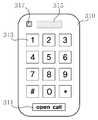
도 6에 도시된 바와 같이, 입력 패널부(310)는 문자열 입력이 가능한 숫자 버튼(313), 단말기(100)와 근거리 통신 또는 접촉 인식을 위한 통신 패널(315), 도어록 유니트(300)의 잠금 및 해제를 요청하는 오픈 콜 버튼(311), 도어에 접근하는 사람을 확인하는 센서(317)를 포함할 수 있다.6, the
숫자 버튼(313)은 전자키의 문자열을 사용자가 직접 도어록에 입력하기 위한 버튼일 수 있다.The
통신 패널(315)은 근거리 통신 또는 RFID(Radio Frequency IDentification)로 단말기(100)의 전자키를 인식하기 위한 것일 수 있다. 통신 패널(315)을 통해서 사용자는 버튼 입력없이 단말기(100)를 도어록 유니트(300)에 접근 또는 접촉시키는 동작으로 도어록 유니트(300)에 전자키를 입력할 수 있다.The
오픈 콜 버튼(311)은 제3의 사용자가 단말기(100) 없이 도어록 유니트(300)와 중계 서버 유니트(200)를 통해서 도어록 유니트(300)의 소유주의 단말기(100)인 제1 단말기(110)에 도어의 잠금 또는 해제 요청을 하기 위한 버튼일 수 있다.The
입력 패널부(310)의 오픈 콜 버튼(311)을 통해서 도어의 잠금 또는 해제 요청이 입력될 시, 중계 유니트는 제1 단말기(110)에 도어의 잠금 또는 해제 요청에 대한 허용 여부의 알림 메시지를 발송할 수 있다. 제1 단말기(110)의 사용자가 메시지 확인 후 허용에 대한 답을 입력하면, 입력 결과는 중계 서버 유니트(200)를 통해 다시 도어록 유니트(300)에 전달되고 제어부(330)는 입력 결과에 따라 액츄에이터부(350)를 작동시킬 수 있다.When a request for locking or unlocking the door is input through the
센서(317)는 영상을 촬영할 수 있는 카메라, 지문 인식 모듈, 홍채 인식 모듈일 수 있다.The
입력 패널부(310) 또는 제2 단말기(130)를 통해서 도어의 잠금 또는 해제 요청이 입력될 시, 센서(317)는 도어의 잠금 또는 해제 요청자를 촬영 또는 스캔할 수 있다. 센서(317)가 촬영 또는 스캔한 데이터는 제1 단말기(110)로 전달되어 제1 단말기(110) 사용자가 영상으로 확인할 수 있다.The
다른 실시예로, 중계 서버 유니트(200) 또는 제1 단말기(110) 또는 제어부(330)에는 측정값 판별 기준 데이터가 입력될 수 있다. 측정값 판별 기준 데이터는 사전에 센서(317) 또는 제1 단말기(110)를 통해서 입력된 도어의 잠금 또는 해제 요청자의 얼굴, 지문, 홍채 등의 영상일 수 있다. 측정값 판별 기준 데이터는 센서(317)로 측정된 영상과 일치율을 판별하는 기준일 수 있다. 제1 단말기(110)는 일치율을 판별하는 위치를 설정할 수 있다. 예를 들어 제1 단말기(110)는 일치율을 판별하는 장치를 중계 서버 유니트(200), 제1 단말기(110), 제어부(330) 중 적어도 하나 이상으로 설정할 수 있다. 판별 위치로 설정된 모든 장치에서 센서(317)가 촬영 또는 스캔한 영상과 측정값 판별 기준 데이터와 일치율이 일정 값 이상으로 판별될 때 도어의 잠금 또는 해제를 허용될 수 있다.In another embodiment, measured value discrimination reference data may be input to the
다른 실시예로 본 발명의 입력 패널부(310)는 보안을 위해서 도 7에 도시한 바와 같이, 숫자 버튼(313)을 생략하고 오픈 콜 버튼(311)과 통신 패널(315), 센서(317)만을 구비할 수도 있다.7, the
이하, 본 발명의 스마트 도어록의 기능 및 작동을 다시 한번 상세히 설명한다.Hereinafter, the function and operation of the smart door lock of the present invention will be described in detail.
도시된 도 1은 본 발명의 스마트 도어록의 통신 연결 상태를 나타낸다. 본 발명의 스마트 도어록은 단말기(100)와 도어록 유니트(300)가 직접 통신할 수도 있지만, 중계 서버 유니트(200)를 통해서 통신 연결된다. 중계 서버 유니트(200)가 통신 노드가 됨으로써, 한 단말기(100)가 복수의 도어록 유니트(300)를 제어하거나 복수의 단말기(100)가 하나의 도어록 제어하는 것이 용이해진다. 또한 중계 통신망을 이용함으로써, 원거리 통신이 용이 해진다. 따라서 1인이 다세대를 관리하는 경우나 다수가 공공 시설 등을 관리하는 경우 용이할 수 있다.1 shows a communication connection state of a smart door lock according to the present invention. The smart door lock of the present invention may be directly communicated with the terminal 100 and the
도시된 도 2는 근거리 통신 또는 RFID 등으로 단말기(100)와 도어록 유니트(300)가 직접 통신하여 전자키를 입력하는 경우다. 이 경우에 도어록 유니트(300)는 전자키를 사용하여 도어를 잠금 또는 해제한 단말기(100)의 단말기 식별 코드를 중계 서버 유니트(200)에 전송하여 작동 기록을 저장할 수 있다.2 shows a case where the terminal 100 and the
도시된 도 3은 입력 패널부(310)의 오픈 콜 버튼(311)을 통해서 도어록 유니트(300)를 잠금 또는 해제하는 동작을 나타낸다. 오픈 콜 버튼(311)으로 도어의 잠금 또는 해제 요청이 도어록 유니트(300)에 입력되면, 요청 신호는 중계 서버 유니트(200)에 전달 되고, 중계 서버 유니트(200)는 요청의 승인에 대한 메시지를 가구주의 단말기(100)인 제1 단말기(110)에 발송한다. 제1 단말기(110)에서 승인이 되면 중계 서버 유니트(200)는 전자키를 도어록 유니트(300)의 전자키 매칭부(331)에 전송한다. 전송된 전자키가 올바르다면 전자키 매칭부(331)는 제어 허용 신호를 액츄에이터 제어부(333)에 전달하고 액츄에이터 제어부(333)는 액츄에이터부(350)를 제어하여 도어를 잠금 또는 해제한다.3 shows an operation of locking or unlocking the
도시된 도 4 내지 5는 전자키의 전달과정을 나타낸다. 도 4에 도시된 바와 같이, 제1 단말기(110)에서 중계 서버 유니트(200)를 통해서 제2 단말기(130)로 전자키를 전달하는 것이 가능하다. 또한 제2 단말기(130)의 요청에 의해 중계 서버 유니트(200)를 통해서 제1 단말기(110)의 승인 후 전자키를 제2 단말기(130)에 전달하는 것이 가능하다.Figs. 4 to 5 show the process of transferring an electronic key. It is possible to transfer the electronic key from the
이상에서 본 발명에 따른 실시예들이 설명되었으나, 이는 예시적인 것에 불과하며, 당해 분야에서 통상적 지식을 가진 자라면 이로부터 다양한 변형 및 균등한 범위의 실시예가 가능하다는 점을 이해할 것이다. 따라서, 본 발명의 진정한 기술적 보호 범위는 다음의 특허청구범위에 의해서 정해져야 할 것이다.
While the invention has been shown and described with reference to certain preferred embodiments thereof, it will be understood by those skilled in the art that various changes and modifications may be made without departing from the spirit and scope of the invention as defined by the appended claims. Accordingly, the true scope of the present invention should be determined by the following claims.
100...단말기110...제1 단말기
130...제2 단말기200...중계 서버 유니트
300...도어록 유니트310...입력 패널부
311...오픈 콜 버튼313...숫자 버튼
315...통신 패널317...센서
330...제어부331...전자키 매칭부
333...액츄에이터 제어부350...액츄에이터부100 ... terminal 110 ... first terminal
130 ...
300 ...
311 ...
315 ...
330 ...
333 ...
Claims (11)
Translated fromKorean상기 도어록 유니트의 잠금 또는 해제를 요청하는 단말기; 및
상기 도어록 유니트 및 상기 단말기에 통신 연결되는 중계 서버 유니트;를 포함하고,
상기 단말기는 제1 단말기 및 제2 단말기를 포함하며,
상기 제1 단말기는 상기 도어록 유니트의 소유주가 사용하는 단말기이고,
상기 제2 단말기는 상기 제1 단말기에 상기 도어록 유니트의 잠금 또는 해제를 요청하는 사람의 단말기이며,
상기 제2 단말기는 상기 중계 서버 유니트에 상기 도어의 잠금 또는 해제 요청이 가능하고,
상기 중계 서버 유니트는 상기 제2 단말기의 요청에 대한 알림 메시지를 상기 제1 단말기로 발송하며,
상기 중계 서버 유니트는 상기 제1 단말기에서 상기 제2 단말기의 요청이 승인되면, 상기 도어록 유니트를 잠그거나 상기 도어록 유니트의 잠금을 해제시키고,
상기 제1 단말기는 상기 중계 서버 유니트에 일부 제2 단말기의 요청 알림 메시지를 차단 등록하며,
상기 중계 서버 유니트는 상기 제1 단말기에 의해 차단 등록된 상기 일부 제2 단말기의 도어 잠금 또는 해제 요청에 대한 알림 메시지를 상기 제1 단말기로 미전달하는 스마트 도어록.
A door lock unit for locking or unlocking the door;
A terminal for requesting locking or unlocking of the door lock unit; And
And a relay server unit communicably connected to the door lock unit and the terminal,
Wherein the terminal comprises a first terminal and a second terminal,
The first terminal is a terminal used by the owner of the door lock unit,
The second terminal is a terminal of a person requesting the first terminal to lock or unlock the door lock unit,
Wherein the second terminal is capable of requesting the relay server unit to lock or unlock the door,
The relay server unit sends a notification message of the request of the second terminal to the first terminal,
The relay server unit may lock the door lock unit or unlock the door lock unit when the request of the second terminal is approved by the first terminal,
The first terminal blocks the request notification message of some second terminals to the relay server unit,
Wherein the relay server unit forwards the notification message of the door lock or unlock request of the part of the second terminal, which is blocked and registered by the first terminal, to the first terminal.
상기 중계 서버 유니트에는,
적어도 하나 이상의 상기 단말기의 단말기 식별 코드 및 적어도 하나 이상의 상기 도어록 유니트의 도어록 식별 코드가 등록되는 스마트 도어록.
The method according to claim 1,
In the relay server unit,
Wherein at least one terminal identification code of the terminal and at least one door lock identification code of the door lock unit are registered.
상기 중계 서버 유니트에는 상기 단말기의 단말기 식별 코드와 상기 도어록 유니트의 도어록 식별 코드가 매칭되어 등록되고,
상기 단말기가 상기 도어에 대한 잠금 또는 해제 명령을 상기 중계 서버 유니트에 전송할 시,
상기 중계 서버 유니트는 상기 단말기 식별 코드에 매칭된 상기 도어록 유니트에 상기 도어록 유니트의 작동 코드가 되는 전자키를 전송하는 스마트 도어록.The method according to claim 1,
The terminal identification code of the terminal and the door lock identification code of the door lock unit are registered in the relay server unit,
When the terminal transmits a lock or unlock command for the door to the relay server unit,
Wherein the relay server unit transmits an electronic key serving as an operation code of the door lock unit to the door lock unit matched with the terminal identification code.
Priority Applications (1)
| Application Number | Priority Date | Filing Date | Title |
|---|---|---|---|
| KR1020150082818AKR101744571B1 (en) | 2015-06-11 | 2015-06-11 | A smart door-lock |
Applications Claiming Priority (1)
| Application Number | Priority Date | Filing Date | Title |
|---|---|---|---|
| KR1020150082818AKR101744571B1 (en) | 2015-06-11 | 2015-06-11 | A smart door-lock |
Publications (2)
| Publication Number | Publication Date |
|---|---|
| KR20160146128A KR20160146128A (en) | 2016-12-21 |
| KR101744571B1true KR101744571B1 (en) | 2017-06-09 |
Family
ID=57735095
Family Applications (1)
| Application Number | Title | Priority Date | Filing Date |
|---|---|---|---|
| KR1020150082818AActiveKR101744571B1 (en) | 2015-06-11 | 2015-06-11 | A smart door-lock |
Country Status (1)
| Country | Link |
|---|---|
| KR (1) | KR101744571B1 (en) |
Cited By (1)
| Publication number | Priority date | Publication date | Assignee | Title |
|---|---|---|---|---|
| KR20200042281A (en) | 2018-10-15 | 2020-04-23 | 주식회사 빈자리 | Smart door lock |
Families Citing this family (3)
| Publication number | Priority date | Publication date | Assignee | Title |
|---|---|---|---|---|
| KR102458479B1 (en)* | 2017-09-28 | 2022-10-25 | 삼성전자 주식회사 | Electronic device and method for controlling using the electronic device |
| CN113668950B (en)* | 2021-09-15 | 2025-04-25 | 中山市基信锁芯有限公司 | A nanny lock capable of switching use states |
| CN119339468A (en)* | 2024-12-20 | 2025-01-21 | 杭州涂鸦信息技术有限公司 | Smart door lock and unlocking method and system thereof |
Citations (4)
| Publication number | Priority date | Publication date | Assignee | Title |
|---|---|---|---|---|
| KR100795587B1 (en)* | 2006-10-26 | 2008-01-21 | 주식회사 케이티프리텔 | Electronic key providing system and method, terminal for same and recording medium therefor |
| KR100811245B1 (en)* | 2006-09-20 | 2008-03-07 | 주식회사 아이리스 | Digital door lock device with video transmission |
| KR100969594B1 (en)* | 2009-10-29 | 2010-07-14 | (주)라우즈미 | Doorlock control system and method thereof |
| JP2015007309A (en)* | 2013-06-24 | 2015-01-15 | 美和ロック株式会社 | Key distribution system and key distribution method |
Family Cites Families (1)
| Publication number | Priority date | Publication date | Assignee | Title |
|---|---|---|---|---|
| KR100318915B1 (en) | 1999-12-14 | 2001-12-29 | 윤종용 | Door rock apparatus using identity information of portable radio telephone and method thereof |
- 2015
- 2015-06-11KRKR1020150082818Apatent/KR101744571B1/enactiveActive
Patent Citations (4)
| Publication number | Priority date | Publication date | Assignee | Title |
|---|---|---|---|---|
| KR100811245B1 (en)* | 2006-09-20 | 2008-03-07 | 주식회사 아이리스 | Digital door lock device with video transmission |
| KR100795587B1 (en)* | 2006-10-26 | 2008-01-21 | 주식회사 케이티프리텔 | Electronic key providing system and method, terminal for same and recording medium therefor |
| KR100969594B1 (en)* | 2009-10-29 | 2010-07-14 | (주)라우즈미 | Doorlock control system and method thereof |
| JP2015007309A (en)* | 2013-06-24 | 2015-01-15 | 美和ロック株式会社 | Key distribution system and key distribution method |
Cited By (1)
| Publication number | Priority date | Publication date | Assignee | Title |
|---|---|---|---|---|
| KR20200042281A (en) | 2018-10-15 | 2020-04-23 | 주식회사 빈자리 | Smart door lock |
Also Published As
| Publication number | Publication date |
|---|---|
| KR20160146128A (en) | 2016-12-21 |
Similar Documents
| Publication | Publication Date | Title |
|---|---|---|
| US11893850B2 (en) | Wireless tag-based lock actuation systems and methods | |
| US7741969B2 (en) | Door entry security device with electronic lock | |
| US10529160B2 (en) | Method for controlling door lock of home network system | |
| KR101595413B1 (en) | Access control system and method with structure type approved by hierarchical manager based on ICT convergence technology | |
| US20170263067A1 (en) | Smart lock systems and methods | |
| WO2001052561A2 (en) | Method and apparatus for providing access to a secure region | |
| KR101744571B1 (en) | A smart door-lock | |
| US11380153B2 (en) | System for receiving delivery items and method therefor | |
| US20180114384A1 (en) | Cloud-based keyless access control system for housing facilities | |
| KR100795587B1 (en) | Electronic key providing system and method, terminal for same and recording medium therefor | |
| KR101954449B1 (en) | Smart door lock and its operating method | |
| US20220327881A1 (en) | System for receiving delivery items and method therefor | |
| KR20140117264A (en) | Entry management aparatus and method for controlling access using digital door lock and wireless telecommunication terminal | |
| JP2017214702A5 (en) | ||
| JP2004120257A (en) | Lock management system and lock management method | |
| KR101025830B1 (en) | Fingerprint Security System | |
| Raju et al. | Smart lock controlled using voice call | |
| JP7181710B2 (en) | Entry/exit gate control system | |
| JP4344303B2 (en) | Entrance / exit management system | |
| KR20160109899A (en) | Mobile, doorlock management method using the mobile and recording media storing program performing the said method | |
| KR20150114618A (en) | The Method to be controlled the Door Camera and Doorlock by SmartPhone with NFC Function Based on M2M in Mobile Network and the Equipment for it | |
| JP4541835B2 (en) | Entrance management system | |
| TW201800652A (en) | Door access control system with automatic unlocking function and unlocking method thereof that comprises a door lock controller and an electronic device carried by a user such that when the electronic device is approaching the door lock controller, the door lock controller, upon identifying the user, automatically unlock the door lock | |
| KR100718196B1 (en) | Multilevel Security Devices, Systems and Methods | |
| JP6796804B2 (en) | Electric lock system and electric lock device |
Legal Events
| Date | Code | Title | Description |
|---|---|---|---|
| A201 | Request for examination | ||
| PA0109 | Patent application | Patent event code:PA01091R01D Comment text:Patent Application Patent event date:20150611 | |
| PA0201 | Request for examination | ||
| E902 | Notification of reason for refusal | ||
| PE0902 | Notice of grounds for rejection | Comment text:Notification of reason for refusal Patent event date:20160823 Patent event code:PE09021S01D | |
| PG1501 | Laying open of application | ||
| E90F | Notification of reason for final refusal | ||
| PE0902 | Notice of grounds for rejection | Comment text:Final Notice of Reason for Refusal Patent event date:20170220 Patent event code:PE09021S02D | |
| E701 | Decision to grant or registration of patent right | ||
| PE0701 | Decision of registration | Patent event code:PE07011S01D Comment text:Decision to Grant Registration Patent event date:20170518 | |
| GRNT | Written decision to grant | ||
| PR0701 | Registration of establishment | Comment text:Registration of Establishment Patent event date:20170601 Patent event code:PR07011E01D | |
| PR1002 | Payment of registration fee | Payment date:20170602 End annual number:3 Start annual number:1 | |
| PG1601 | Publication of registration | ||
| PR1001 | Payment of annual fee | Payment date:20200511 Start annual number:4 End annual number:4 | |
| PR1001 | Payment of annual fee | Payment date:20210531 Start annual number:5 End annual number:5 | |
| PR1001 | Payment of annual fee | Payment date:20220531 Start annual number:6 End annual number:6 | |
| PR1001 | Payment of annual fee | Payment date:20230531 Start annual number:7 End annual number:7 | |
| PR1001 | Payment of annual fee | Payment date:20250512 Start annual number:9 End annual number:9 |