KR101738043B1 - electrical vehicle charging system and method - Google Patents
electrical vehicle charging system and methodDownload PDFInfo
- Publication number
- KR101738043B1 KR101738043B1KR1020150043483AKR20150043483AKR101738043B1KR 101738043 B1KR101738043 B1KR 101738043B1KR 1020150043483 AKR1020150043483 AKR 1020150043483AKR 20150043483 AKR20150043483 AKR 20150043483AKR 101738043 B1KR101738043 B1KR 101738043B1
- Authority
- KR
- South Korea
- Prior art keywords
- electric vehicle
- microcontroller
- charger
- connector
- charging
- Prior art date
- Legal status (The legal status is an assumption and is not a legal conclusion. Google has not performed a legal analysis and makes no representation as to the accuracy of the status listed.)
- Expired - Fee Related
Links
Images


Classifications
- B60L11/1861—
- B60L2230/16—
- Y—GENERAL TAGGING OF NEW TECHNOLOGICAL DEVELOPMENTS; GENERAL TAGGING OF CROSS-SECTIONAL TECHNOLOGIES SPANNING OVER SEVERAL SECTIONS OF THE IPC; TECHNICAL SUBJECTS COVERED BY FORMER USPC CROSS-REFERENCE ART COLLECTIONS [XRACs] AND DIGESTS
- Y02—TECHNOLOGIES OR APPLICATIONS FOR MITIGATION OR ADAPTATION AGAINST CLIMATE CHANGE
- Y02T—CLIMATE CHANGE MITIGATION TECHNOLOGIES RELATED TO TRANSPORTATION
- Y02T10/00—Road transport of goods or passengers
- Y02T10/60—Other road transportation technologies with climate change mitigation effect
- Y02T10/70—Energy storage systems for electromobility, e.g. batteries
- Y—GENERAL TAGGING OF NEW TECHNOLOGICAL DEVELOPMENTS; GENERAL TAGGING OF CROSS-SECTIONAL TECHNOLOGIES SPANNING OVER SEVERAL SECTIONS OF THE IPC; TECHNICAL SUBJECTS COVERED BY FORMER USPC CROSS-REFERENCE ART COLLECTIONS [XRACs] AND DIGESTS
- Y02—TECHNOLOGIES OR APPLICATIONS FOR MITIGATION OR ADAPTATION AGAINST CLIMATE CHANGE
- Y02T—CLIMATE CHANGE MITIGATION TECHNOLOGIES RELATED TO TRANSPORTATION
- Y02T90/00—Enabling technologies or technologies with a potential or indirect contribution to GHG emissions mitigation
- Y02T90/10—Technologies relating to charging of electric vehicles
- Y02T90/16—Information or communication technologies improving the operation of electric vehicles
Landscapes
- Electric Propulsion And Braking For Vehicles (AREA)
- Charge And Discharge Circuits For Batteries Or The Like (AREA)
Abstract
Translated fromKoreanDescription
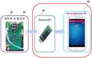
Translated fromKorean본 발명은 전기자동차 충전 시스템 및 방법에 관한 것으로, 더욱 상세하게는 기존의 완속 충전기에서 스크린을 없애고 스마트폰으로 충전상태를 보여줌으로써 충전기를 구매할 때 좀 더 저렴하게 소비자들에게 제공할 수 있고, 장소에 구애받지 않고 스마트폰을 통하여 차량의 충전상태를 알 수 있는 전기자동차 충전 시스템 및 방법에 관한 것이다.The present invention relates to an electric vehicle charging system and method, and more particularly, to an electric vehicle charging system which eliminates a screen in a conventional slow charger and shows a state of charge by a smart phone, And more particularly, to an electric vehicle charging system and method capable of knowing a state of charge of a vehicle through a smart phone without regard to the state of the vehicle.
자동차는 인류의 문명에 매우 큰 기여를 한 발명품이다. 그러나, 자동차를 사용하려면 한정된 자원인 석유를 사용해야만 한다. 또한 자동차를 이용하기 위해 석유를 소비하는 과정에서 환경오염의 문제가 발생한다. 지구상에 매장된 석유자원의 고갈과 친환경 규제 강화로 전기로 갈 수 있는 전기자동차가 개발되었다.The automobile is an invention that made a great contribution to human civilization. However, to use a car, you have to use a limited amount of oil. In addition, environmental pollution problems arise in the process of consuming petroleum to use automobiles. The depletion of petroleum resources buried on the earth and the reinforcement of environmentally friendly regulations have led to the development of electric vehicles that can go to electricity.
개발되고 있는 전기자동차에는 순수 전기자동차(Batttery Powered Electric Vehicle)와 전동기와 엔진을 함께 이용하는 하이브리드 전기 자동차(Hybrid Electric Vehicle) 및 연료전지 전기 자동차(Fuel Cell Electric Vehicle) 등이 있다. 특히, 플러그인(Plug-in) 하이브리드 전기자동차와 순수 전기 자동차는 차량 내부에 구비된 고압 배터리로부터 구동에 필요한 전력을 공급받는 전기자동차이다.Hybrid Electric Vehicle and Fuel Cell Electric Vehicle, which use a Batttery Powered Electric Vehicle, an electric motor and an engine together, are examples of developed electric vehicles. In particular, a plug-in hybrid electric vehicle and a pure electric vehicle are electric vehicles supplied with power required for driving from a high-voltage battery provided inside the vehicle.
도 1은 일반적인 제어 파일럿(PILOT) 등가회로를 나타내는 도면으로서, 종래에는 전기자동차(EV)(20)를 충전할 때 충전순서는 전기자동차(20)가 연결되기 전까지 충전기(10)는 대기상태로 있다가 전기자동차(20)의 인렛과 충전기(10)의 커넥터가 연결되면 충전기(10)에서 AC 전압이 온보드 충전기(On-board Charger)에 인가되고, 온보드 충전기(On-board Charger)에 저장된 전압이 전기자동차(20)의 배터리에 공급되어 충전이 이루어졌다. 즉, 종래에는 전기자동차를 충전할 때 충전기는 단지 전기자동차에 AC 전원을 공급하는 역할을 한다.FIG. 1 is a diagram showing a general control pilot (PILOT) equivalent circuit. In the past, when the electric vehicle (EV) 20 is charged, the charging sequence is such that the
도 2는 통상적인 동작 상태에서 충전기의 전형적인 충전 사이클을 나타내는 도면으로서, 이에 대한 연결 시퀀스를 하기의 표 1에서 설명한다.Fig. 2 is a diagram showing a typical charging cycle of the charger in a normal operating state, and the connection sequence for this is shown in Table 1 below.
C, DB →
C, D
→ BC, D
→ B
도 2는 기존 충전기의 일반적인 충전 사이클을 나타내고, 표 1은 충전 사이클에 대한 동작 순서를 나타낸다. 도 3은 충전기 제어부의 제어 흐름을 나타내는 도면으로서, 도 2와 표 1을 비교하여 살펴보면 충전기는 12V를 유지하고 있다가 전기자동차의 인렛에 충전기 커넥터가 연결되면 9V로 전압이 떨어진다. 이 때 파일럿 회로(PILOT Circuit)의 S2 스위치가 닫히면서 전압이 6V로 떨어진다. 전기자동차에서 전류를 도출하여 차량충전상태를 확인하고 충전완료명령이 전기자동차에서 전달되면 충전기 커넥터를 차량 인렛에서 분리한다. 이 때 파일럿 회로(PILOT Circuit)에 있는 S2 스위치는 오프(OFF)되고 연결이 완전이 해체된다. 그리고 충전기는 다시 12V를 유지한다.Figure 2 shows a typical charge cycle of an existing charger, and Table 1 shows the sequence of operations for a charge cycle. FIG. 3 is a view showing a control flow of the charger control unit. Referring to FIG. 2 and Table 1, when the charger maintains 12V, when the charger connector is connected to the inlet of the electric vehicle, the voltage drops to 9V. At this time, the S2 switch of the pilot circuit (PILOT Circuit) is closed and the voltage drops to 6V. When electric current is drawn from the electric vehicle to check the state of charge of the vehicle and the charge completion command is transmitted from the electric vehicle, disconnect the charger connector from the vehicle inlet. At this time, the S2 switch in the pilot circuit (PILOT Circuit) is turned off and the connection is completely disassembled. And the charger maintains 12V again.
도 4는 종래의 충전기에서 유저 인터페이스(UI)로의 신호 흐름을 나타내는 도면으로서, 충전기(10)의 내부에 있는 제어부(11)에서 RS232 통신부(12)를 통하여 충전기(10)의 내부에 부착되어 있는 디스플레이 유저 인터페이스(UI)(13)로 신호가 전송된다.4 is a diagram showing a signal flow from a conventional charger to a user interface (UI), in which a
전술한 바와 같이 종래에는 전기자동차를 충전하기 위한 완속 충전기에 충전 상태를 보여주기 위한 스크린이 구비되어 충전기의 가격이 상승되는 요인이 되었으며, 충전기의 제어부를 제어하기 어려운 문제점이 있었다.As described above, conventionally, there is a disadvantage that a slow charging device for charging an electric vehicle is equipped with a screen for showing the charged state, which increases the price of the charging device, and it is difficult to control the control device of the charging device.
또한 종래의 충전기는 전력사용 비용이 비교적 저렴한 심야전력을 이용하여 전기자동차를 충전할 수 있는 시스템이 구비되지 않아 전기자동차의 충전 비용을 줄일 수 없다는 문제점이 있었다.Also, the conventional charger is not equipped with a system that can charge the electric vehicle by using the nighttime power, which is relatively inexpensive to use the electric power, so that the charging cost of the electric vehicle can not be reduced.
본 발명은 이와 같은 문제점을 해결하기 위해 창안된 것으로서, 기존의 완속 충전기에서 스크린을 없애고 스마트폰으로 충전상태를 보여줌으로써 충전기를 구매할 때 좀 더 저렴하게 소비자들에게 제공할 수 있고, 장소에 구애받지 않고 스마트폰을 통하여 차량의 충전상태를 알 수 있기 때문에 편리함까지 제공할 수 있도록 한 전기자동차 충전 시스템 및 방법을 제공함을 목적으로 한다.Disclosure of Invention Technical Problem [8] Accordingly, the present invention has been made to solve the above-mentioned problems, and it is an object of the present invention to provide a charger that eliminates a screen in a conventional slow charger and displays a charged state with a smart phone, The present invention also provides an electric vehicle charging system and method that can provide convenience even when a vehicle is charged through a smart phone.
또한, 유저 인터페이스 장치인 스마트폰에 전기자동차를 심야전력을 사용하여 충전할 수 있는 충전 예약기능 프로그램이 탑재됨으로써 정해진 심야시간에 전기자동차의 충전이 이루어져 전기자동차 충전비용을 줄일 수 있고 부하 평준화에 기여할 수 있도록 한 전기자동차 충전 시스템 및 방법을 제공함을 목적으로 한다.In addition, a charging reservation function program that can charge an electric vehicle using a night-time electric power to a smart phone as a user interface device is charged, thereby charging the electric vehicle in a predetermined midnight time, thereby reducing electric vehicle charging cost and contributing to load leveling. And to provide a charging system and method for an electric vehicle.
상기한 목적을 달성하기 위한 본 발명에 따른 전기자동차 충전 시스템의 일 측면에 따르면, 전기자동차의 충전상태를 파악하여 충전기를 제어하고 심야전력을 사용하여 전기자동차의 충전이 가능한 프로그램이 탑재되어 사용자를 인식하고 충전기의 상태를 실시간으로 모니터링하는 유저 인터페이스 장치; 및
상기 유저 인터페이스 장치의 제어에 따라 충전기의 상태를 확인하여 상기 유저 인터페이스 장치로 데이터를 선택하여 송신하고 심야전력을 예약된 시간에 사용하여 전기자동차를 충전하는 기능 및, 배터리 충전량 상태에 따라 파악된 충전시간에 충전을 실시하는 기능을 구비하는 충전기를 포함한다.According to an aspect of the present invention, there is provided a charging system for an electric vehicle, comprising: a charging device for charging an electric vehicle; A user interface device for recognizing and monitoring the state of the charger in real time; And
A function of checking the state of the charger according to the control of the user interface device and selecting and transmitting data to the user interface device and charging the electric vehicle using the midnight power at a reserved time, And a charger having a function of performing charging in a predetermined time.
또한, 상기한 목적을 달성하기 위한 본 발명에 따른 전기자동차 충전 방법의 일 측면에 따르면, (a) 충전기의 커넥터에서 마이크로 컨트롤러로 정상상태 메시지를 송신하는 단계; (b) 상기 마이크로 컨트롤러에서 송신할 데이터를 선택하여 블루투스 모듈로 송신하는 단계; (c) 상기 블루투스 모듈에서 수신한 데이터를 유저 인터페이스 장치로 송신하는 단계; (d) 상기 블루투스 모듈에서 상기 유저 인터페이스 장치로부터 정상상태 메시지를 수신하여 상기 마이크로 컨트롤러로 데이터를 송신하는 단계; (e) 상기 커넥터에서 상기 마이크로 컨트롤러로 전기자동차가 연결 알림 신호를 송신하는 단계; (f) 상기 마이크로 컨트롤러에서 상기 유저 인터페이스 장치로부터의 충전 요청에 따라 상기 커넥터로 충전 제어 온(ON)을 명령하는 단계; 및 (g) 상기 커넥터에서 상기 마이크로 컨트롤러의 명령에 따라 전기자동차로 전원을 공급하는 단계;를 포함하고, 상기 단계(g) 이후에, (h) 상기 유저 인터페이스 장치에서 상기 마이크로 컨트롤러로 전기자동차의 심야시간 충전을 위한 예약을 명령하는 단계; (i) 상기 마이크로 컨트롤러에서 상기 커넥터로 출력 제어 오프(OFF)를 명령하는 단계; (j) 상기 커넥터에서 상기 마이크로 컨트롤러로 전기자동차의 심야시간 충전을 위한 예약된 시간임을 알리는 단계; (k) 상기 마이크로 컨트롤러에서 상기 커넥터로 충전 제어 온(ON)을 명령하는 단계; 및 (l) 상기 커넥터에서 상기 마이크로 컨트롤러의 명령에 따라 전기자동차로 전원을 공급하는 단계; (m) 전기자동차에서 상기 마이크로 컨트롤러로 배터리 충전량 상태를 송신하는 단계; (n) 상기 마이크로 컨트롤러에서 상기 커넥터로, 상기 수신한 배터리 충전량 상태에 따라 파악된 충전시간을 명령하는 단계; (o) 상기 커넥터에서 상기 마이크로 컨트롤러로부터 명령된 충전시간이 되면 전기자동차로 전원을 공급하는 단계; (p) 전기자동차에서 상기 마이크로 컨트롤러로 배터리 충전완료 및 상기 커넥터 해제를 명령하는 단계; 및 (q) 상기 마이크로 컨트롤러의 제어에 의해 상기 커넥터가 전기자동차에서 해제되는 단계를 포함한다.According to another aspect of the present invention, there is provided an electric vehicle charging method comprising the steps of: (a) transmitting a steady state message from a connector of a charger to a microcontroller; (b) selecting data to be transmitted from the microcontroller and transmitting the selected data to the Bluetooth module; (c) transmitting data received from the Bluetooth module to a user interface device; (d) receiving a steady state message from the user interface device in the Bluetooth module and transmitting data to the microcontroller; (e) transmitting an announcement signal from the connector to the microcontroller by the electric vehicle; (f) instructing the microcontroller to turn on charge control ON with the connector according to a charging request from the user interface device; And (g) powering the electric vehicle from the connector at the command of the microcontroller, wherein after step (g): (h) Commanding a reservation for a late night time charge; (i) commanding output control off (OFF) from the microcontroller to the connector; (j) informing the microcontroller at the connector that it is a reserved time for charging the electric vehicle at night time; (k) instructing the microcontroller to turn on charge control ON with the connector; And (l) powering the electric vehicle according to an instruction from the microcontroller in the connector; (m) transmitting a battery charge state from the electric vehicle to the microcontroller; (n) instructing, from the microcontroller to the connector, a charge time determined based on the received battery charge amount status; (o) supplying electric power to the electric vehicle when charging time is reached from the microcontroller in the connector; (p) instructing the microcontroller to charge the battery and to release the connector in the electric vehicle; And (q) releasing the connector from the electric vehicle under the control of the microcontroller.
본 발명에 의하면, 기존의 완속 충전기에서 스크린을 없애고 스마트폰으로 충전상태를 보여줌으로써 충전기를 구매할 때 좀 더 저렴하게 소비자들에게 제공할 수 있고, 장소에 구애받지 않고 스마트폰을 통하여 차량의 충전상태를 알 수 있기 때문에 편리함까지 제공하는 효과가 있다.According to the present invention, it is possible to provide the consumers with a lower cost when purchasing the charger by removing the screen from the conventional slow charger and showing the charging state with the smart phone, and it is possible to provide the charging state It is advantageous to provide convenience.
또한, 유저 인터페이스 장치인 스마트폰에 전기자동차를 심야전력을 사용하여 충전할 수 있는 충전 예약기능 프로그램이 탑재됨으로써 정해진 심야시간에 전기자동차의 충전이 이루어져 전기자동차 충전비용을 줄일 수 있고 부하 평준화에 기여할 수 있는 효과가 있다.In addition, a charging reservation function program that can charge an electric vehicle using a night-time electric power to a smart phone as a user interface device is charged, thereby charging the electric vehicle in a predetermined midnight time, thereby reducing electric vehicle charging cost and contributing to load leveling. There is an effect that can be.
도 1은 일반적인 제어 파일럿(PILOT) 등가회로를 나타내는 도면.
도 2는 통상적인 동작 상태에서 충전기의 전형적인 충전 사이클을 나타내는 도면.
도 3은 충전기 제어부의 제어 흐름을 나타내는 도면.
도 4는 종래의 충전기에서 유저 인터페이스(UI)로의 신호 흐름을 나타내는 도면.
도 5는 본 발명의 일실시예에 따른 충전기에서 유저 인터페이스로 장치로의 신호 흐름을 나타내는 도면.
도 6은 도 5의 실제 하드웨어 구성을 나타내는 도면.
도 7은 도 5에서 마이크로 컨트롤러가 내장된 충전기 제어부에서 유저 인터페이스 장치로의 신호 흐름을 나타내는 도면.
도 8은 도 7의 실제 하드웨어 구성을 나타내는 도면.
도 9는 본 발명의 전기자동차 충전기의 블럭 다이어그램(EV Charger block diagram)을 나타내는 도면.
도 10은 도 5에서 충전기의 마이크로 컨트롤러에서 블루투스 모듈을 통해 유저 인터페이스 장치로 신호가 전송되는 과정을 나타내는 도면.
도 11은 본 발명의 심야 전력을 이용하여 충전을 하기 위한 예약 방법을 나타내는 도면.
도 12는 본 발명의 전기자동차 충전을 위한 제어 방법을 나타내는 도면.
도 13은 본 발명의 심야 전력을 이용하여 충전을 하기 위한 예약 방법을 나타내는 도면.1 shows a general control pilot (PILOT) equivalent circuit;
2 shows a typical charging cycle of a charger in a normal operating state;
3 is a view showing a control flow of the charger control section;
4 shows a signal flow from a conventional charger to a user interface (UI);
5 illustrates signal flow from a charger to a user interface device in accordance with one embodiment of the present invention.
6 is a diagram showing the actual hardware configuration of Fig. 5; Fig.
FIG. 7 is a diagram illustrating a signal flow from a charger control unit with a built-in microcontroller to a user interface device in FIG. 5;
8 is a diagram showing the actual hardware configuration of Fig. 7; Fig.
9 is a view showing an EV Charger block diagram of an electric vehicle charger of the present invention.
10 is a diagram illustrating a process in which a signal is transmitted from a microcontroller of a charger to a user interface device through a Bluetooth module in FIG.
11 is a diagram showing a reservation method for charging using night-time power of the present invention.
12 is a view showing a control method for electric vehicle charging according to the present invention.
13 is a diagram showing a reservation method for charging using the nighttime power of the present invention.
이하 첨부된 도면을 참조로 본 발명의 바람직한 실시예를 상세히 설명하기로 한다. 이에 앞서, 본 명세서 및 청구범위에 사용된 용어나 단어는 통상적이거나 사전적인 의미로 한정해서 해석되어서는 아니되며, 발명자는 그 자신의 발명을 가장 최선의 방법으로 설명하기 위해 용어의 개념을 적절하게 정의할 수 있다는 원칙에 입각하여 본 발명의 기술적 사상에 부합하는 의미와 개념으로 해석되어야만 한다. 따라서, 본 명세서에 기재된 실시예와 도면에 도시된 구성은 본 발명의 가장 바람직한 일 실시예에 불과할 뿐이고 본 발명의 기술적 사상을 모두 대변하는 것은 아니므로, 본 출원시점에 있어서 이들을 대체할 수 있는 다양한 균등물과 변형예들이 있을 수 있음을 이해하여야 한다.
Hereinafter, preferred embodiments of the present invention will be described in detail with reference to the accompanying drawings. Prior to this, terms and words used in the present specification and claims should not be construed as limited to ordinary or dictionary terms, and the inventor should appropriately interpret the concepts of the terms appropriately It should be interpreted in accordance with the meaning and concept consistent with the technical idea of the present invention based on the principle that it can be defined. Therefore, the embodiments described in this specification and the configurations shown in the drawings are merely the most preferred embodiments of the present invention and do not represent all the technical ideas of the present invention. Therefore, It is to be understood that equivalents and modifications are possible.
도 5는 본 발명의 일실시예에 따른 충전기에서 유저 인터페이스로 장치로의 신호 흐름을 나타내는 도면이고, 도 6은 도 5의 실제 하드웨어 구성을 나타내는 도면이다.FIG. 5 is a diagram showing a signal flow from a charger to a user interface device according to an embodiment of the present invention, and FIG. 6 is a diagram showing the actual hardware configuration of FIG.
도시된 바와 같이, 본 발명에 따른 충전기(30)는 제어부(31)에서 RS232 통신부(32)를 거쳐 바로 유저 인터페이스 장치(40)로 신호가 전송되지 않고, 모든 신호를 마이크로 컨트롤러(33)에서 받아서 그 중에 필요한 신호를 블루투스 모듈(34)로 보내줄 뿐만 아니라 예약기능을 함께 수행한다. 특히 유저 인터페이스 장치(40)는 기존과 같이 충전기의 내부에 있는 디스플레이 유저 인터페이스(UI)가 아니라 블루투스 모듈(34)을 통해 통신이 가능한 스마트폰을 이용한 유저 인터페이스(UI)로 구성된다.
The
도 7은 도 5에서 마이크로 컨트롤러가 내장된 충전기 제어부에서 유저 인터페이스 장치로의 신호 흐름을 나타내는 도면이고, 도 8은 도 7의 실제 하드웨어 구성을 나타내는 도면이다.FIG. 7 is a diagram illustrating a signal flow from a charger control unit with a built-in microcontroller to a user interface unit in FIG. 5, and FIG. 8 is a diagram showing the actual hardware configuration of FIG.
도시된 바와 같이, 본 발명의 충전기(30)는 제어부(35)와, 통신부(32)와, 블루투스 모듈(34)을 포함하고, 이러한 구성을 갖는 충전기(30)는 유저 인터페이스 장치(40)와 통신한다.The
제어부(35)는 전술한 도 5에서의 마이크로 컨트롤러가 내장되어 필요한 신호를 블루투스 모듈(34)로 보내줄 뿐만 아니라 예약기능을 함께 수행한다. 이러한 예약기능에 대해서는 하기에서 구체적으로 설명하기로 한다. 이러한 제어부(35)는 유저 인터페이스 장치(40)와의 통신에 의해 RS232 신호를 송수신하고, 유저 인터페이스 장치(40)에 의해 제어된다.The
통신부(32)는 RS232 통신방식으로 제어부(35)에서 블루투스 모듈(34)로 신호를 전달한다.The
블루투스 모듈(34)은 제어부(35)에서 전달되되는 신호를 통신부(32)를 통해 수신하여 유저 인터페이스 장치(40)로 전송한다.The
유저 인터페이스 장치(40)는 전술한 바와 같이 블루투스 모듈(34)을 통해 통신이 가능한 유저 인터페이스 장치로서 스마트폰을 유저 인터페이스 장치로 사용 가능하며 그 외에 블루투스 모듈(34)과 통신이 가능한 스마트 기기 등이 사용될 수 있다. 이러한 유저 인터페이스 장치(40)는 기존 충전기에 설치되어 기존 앱을 통해 신호의 값만을 디스플레이하는 것이 아니라, 충전기(30)의 제어부(35)를 제어할 수 있는 앱이 탑재된다.
The
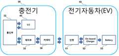
도 9는 본 발명의 전기자동차 충전기의 블럭 다이어그램(EV Charger block diagram)을 나타내는 도면이다.9 is a diagram showing an EV Charger block diagram of an electric vehicle charger according to the present invention.
도시된 바와 같이, 본 발명의 충전기(30)는 통신부(32)와, 유저 인터페이스 장치(40)와, 제어부(35)와, 커넥터(36)를 포함하고, 전기자동차(EV)(50)는 인렛(51)과, 온보드 충전기(On-board Charger)(52)와, 배터리(Battery)(53)를 포함한다.As shown, the
통신부(32)는 스마트폰을 포함하는 스마트 기기 등의 유저 인터페이스 장치(40)와 통신하고 전기자동차(EV)(50)와 신호를 주고 받는다. 전기자동차(EV)(50)의 배터리(Battery)(53) 충전을 위해 충전기(30)의 커넥터(36)가 전기자동차(EV)(50)의 인렛(51)에 연결되면 전기자동차(EV)(50)의 배터리(Battery)(53)의 충전 상태에 관해 전송되는 신호를 유저 인터페이스 장치(40)로 전송하고, 유저 인터페이스 장치(40)에서 전달되는 제어신호를 전기자동차(EV)(50)로 전송한다.The
유저 인터페이스 장치(40)는 전술한 바와 같이 블루투스 모듈을 통해 통신이 가능한 유저 인터페이스 장치로서 스마트폰을 유저 인터페이스 장치로 사용 가능하며 그 외에 블루투스 모듈과 통신이 가능한 스마트 기기 등이 사용될 수 있다. 이러한 유저 인터페이스 장치(40)는 충전기(30)의 제어부(35)를 제어할 수 있는 앱이 탑재된다.The
제어부(35)는 전기자동차(EV)(50)에서 송신되는 배터리의 충전상태에 관한 신호를 수신하여 통신부(32)를 통해 유저 인터페이스 장치(40)로 전달하고, 통신부(32)를 통해 전달되는 유저 인터페이스 장치(40)로부터의 제어신호를 커넥터(36)에 의해 연결된 전기자동차(EV)(50)로 전송한다. 또한 심야전력충전을 위한 예약기능을 함께 수행한다. 이러한 예약기능에 대해서는 하기에서 구체적으로 설명하기로 한다.The
커넥터(36)는 전기자동차(EV)(50)의 충전을 위해 전기자동차(EV)(50)의 인렛(51)에 연결된다.The
전기자동차(EV)(50)의 온보드 충전기(On-board Charger)(52)는 배터리(Battery)(53)의 충전 상태를 측정하여 충전기(30)로 전송하고, 배터리(Battery)(53)의 충전을 위한 전원을 충전기(30)에서 공급받아 저장한다.The on-
이와 같은 구성을 갖는 전기자동차 충전기의 충전 순서는, 전기자동차(50)(EV)가 연결되기 전까지 충전기(30)는 대기상태로 있다가 충전기(30)의 커넥터(36)가 전기자동차(50)(EV)의 인렛(51)에 연결되면 AC 전압이 온보드 충전기(On-board Charger)(52)에 인가되고, 온보드 충전기(On-board Charger)(52)에 저장된 전압이 배터리(Battery)(53)에 공급되어 충전이 이루어진다.The charging sequence of the electric car charger having such a configuration is such that the
전술한 바와 같이, 기존의 충전기와 전기자동차(EV) 간의 통신은 전기자동차에서 충전기에 신호를 보내주는 단방향 통신이었지만, 본 발멸의 충전기와 전기자동차(EV) 간의 통신은 도 9에서와 같이 양방향 통신이 가능하게 하여 온보드 충전기(On-board Charger)에서 배터리(Battery)의 상태를 측정하여 충전기에 보내주면 충전기가 배터리(Battery)의 상태에 따라 충전 시간이나 충전량을 파악하여 충전를 할 수 있는 시스템이다.As described above, the communication between the existing charger and the electric vehicle (EV) is one-way communication in which the electric car transmits a signal to the charger, but the communication between the charger and the electric vehicle (EV) The on-board charger measures the state of the battery and sends it to the charger. In this case, the charger can determine the charging time or the charging amount according to the state of the battery and charge the battery.
전술한 본 발명의 충전기는 기존의 완속 충전기에서 스크린을 없애고 스마트폰으로 충전상태를 보여줌으로써 저가형으로 제조하여 소비자들에게 제공 가능하고, 장소에 구애받지 않고 스마트폰을 통하여 차량의 충전상태를 알 수 있기 때문에 편리함까지 제공한다. 또한 하기에서 설명될 심야전력충전(예약기능) 알고리즘이 탑재되어 전기자동차 충전비용을 줄일 수 있고 부하 평준화에 기여할 수 있다.
The above-described charger of the present invention can be manufactured in a low price and can be provided to consumers by eliminating the screen from the conventional slow charger and showing the charging state with the smart phone, and can know the charging state of the vehicle through the smart phone regardless of the place It is convenient because it is there. In addition, the nighttime power charging (reservation function) algorithm described below can be installed to reduce the charging cost of the electric vehicle and contribute to the load leveling.
도 10은 도 5에서 충전기의 마이크로 컨트롤러에서 블루투스 모듈을 통해 유저 인터페이스 장치로 신호가 전송되는 과정을 나타내는 도면이다.FIG. 10 is a diagram illustrating a process of transmitting a signal from a microcontroller of a charger to a user interface device through a Bluetooth module in FIG.
도시된 바와 같이, 충전기의 상태가 조회(S10)되어 조회된 신호가 출력되면, 충전기의 마이크로 컨트롤러는 RS232 통신부에서 출력되는 신호를 수신하여 확인(S20)한다. 이때 마이크로 컨트롤러는 RS232 통신부에서 출력되는 신호들이 프로토콜 포맷(protocol format)을 나타내는 하기의 표 2에서와 같은 프로토콜 신호들과 같이 동일한 신호들로 송신되는지를 확인한다.As shown in the figure, when the status of the charger is inquired (S10) and the inquired signal is outputted, the microcontroller of the charger receives and confirms the signal outputted from the RS232 communication unit (S20). At this time, the microcontroller confirms whether the signals output from the RS232 communication unit are transmitted with the same signals as the protocol signals shown in Table 2 below, which indicate the protocol format.

이어서, 마이크로 컨트롤러는 충전기의 상태가 정상상태인지를 확인(S30)한다. 이때 충전기의 상태를 확인하는 방법은 하기의 표 3의 항목 중에서 충전기의 상태를 조회하는 명령어인 CMD 값이 영문 소문자 's' 이면 충전기의 상태를 정상상태로 판단한다.Subsequently, the microcontroller checks whether the charger is in a normal state (S30). At this time, the method of checking the state of the charger is determined as the normal state of the charger when the CMD value, which is a command for inquiring the state of the charger among the items of Table 3 below, is in lower case 's'.

이어서, 마이크로 컨트롤러는 블루투스 모듈을 통해 유저 인터페이스 장치로 전송할 신호를 선택(S40)한다. 마이크로 컨트롤러에 의해 선택된 신호는 블루투스 모듈로 전달(S50)되고, 블루투스 모듈에서 스마트폰 등의 유저 인터페이스 장치로 전송(S60)된다. 이때 전송되는 신호는 충전기 유저 인터페이스 프로토콜을 나타내는 하기의 표 4에서와 같이 6. 비상 정지 상태, 11. 파일럿(PILOT) 상태, 16. 스위치 상태, 24. 충전량, 33.누적전력량 등의 신호가 전송된다.Subsequently, the microcontroller selects a signal to be transmitted to the user interface device through the Bluetooth module (S40). The signal selected by the microcontroller is transmitted to the Bluetooth module (S50), and transmitted from the Bluetooth module to the user interface device such as a smart phone (S60). At this time, signals transmitted are signals as shown in Table 4 below, which indicates the charger user interface protocol. 6. Emergency stop state, 11. Pilot state, 16. Switch state, 24. Charge amount, 33. Cumulative power amount, do.
본 발명의 충전기 프로토콜에 대해 살펴보면, 기존의 충전기는 유저 인터페이스(UI)를 통하여 사용자 인식 및 충전기 상태에 대한 실시간 모니터링을 하였다. 그러나 본 발명의 충전기는 기존의 충전기에 사용되는 유저 인터페이스(UI)를 사용하지 않고, 블루투스(Bluetooth)와 충전기의 제어부를 제어할 수 있는 앱이 탑재된 유저 인터페이스 장치인 스마트폰을 이용하여 사용자 인식 및 충전기 상태에 대한 실시간 모니터링을 한다. 이에 의해 본 발명에서는 충전기에 대한 기존의 프로토콜을 분석하여 충전기와 연결된 유저 인터페이스 장치 간에 연동되는 통신 메시지를 확인하고, 분석한 프로토콜 중에 중요 메시지를 유저 인터페이스 장치인 스마트폰을 통해 실시간 모니터링 할 수 있게 된다. 하기의 표 4는 본 발명의 충전기의 유저 인터페이스(UI) 프로토콜을 나타낸다.In the charger protocol of the present invention, a conventional charger real-time monitors user recognition and charger status through a user interface (UI). However, the charger of the present invention does not use a user interface (UI) used in a conventional charger but uses a smart phone, which is a user interface device equipped with an app capable of controlling a control unit of Bluetooth and a charger, And real time monitoring of the charger status. Accordingly, in the present invention, the existing protocol for the charger is analyzed to check the communication message interlocked with the user interface device connected to the charger, and the important message among the analyzed protocols can be monitored in real time through the smart phone as the user interface device . Table 4 below shows the user interface (UI) protocol of the charger of the present invention.
3V:0×04, 0V:0×0512V: 0 占 01, 9V: 0 占 02, 6V: 0 占 03,
3V: 0 × 04, 0V: 0 × 05
9:절상(저전류),10:PWM -12V Fail,
11:MC 융착,12:과전압1: CP, 2: Emergency stop 3: UI card 4: Switch 5: Keypad 6: Cable harness 7: Low current 8:
9: Rising (low current), 10: PWM -12V Fail,
11: MC fusion, 12:
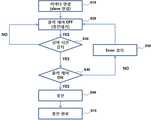
도 11은 본 발명의 심야 전력을 이용하여 충전을 하기 위한 예약 방법을 나타내는 도면이다.11 is a diagram showing a reservation method for charging using night-time power of the present invention.
도시된 바와 같이, 심야 전력을 사용하여 전기자동차를 충전하기 위한 과정을 살펴보면, 먼저 충전기의 커넥터가 전기자동차에 연결(S10)된다.As shown in the figure, a process for charging an electric vehicle using night-time electric power will be described. First, the connector of the charger is connected to the electric vehicle (S10).
충전기는 커넥터가 전기자동차에 연결된 상태에서 전기자동차를 충전하기 위한 출력 제어를 오프(OFF)시켜 충전대기 상태를 유지(S20)한다.The charger turns off the output control for charging the electric vehicle in a state where the connector is connected to the electric vehicle, and maintains the charging standby state (S20).
이어서 충전기는 현재 시간이 심야 시간인지의 여부를 판단(S30)한다. 여기서 심야 시간은 기 설정되어 충전기에서 기 설정된 심야 시간을 기준으로 현재 시간이 심야 시간인지의 여부를 판단할 수 있게 된다.Subsequently, the charger determines whether the current time is the night time (S30). Here, the night time is predefined so that it is possible to determine whether the current time is the night time based on the predetermined night time in the charger.
이어서 충전기는 S30 단계에서 현재 시간이 기 설정된 심야 시간이 아닌 경우에는 계속해서 전기자동차를 충전하기 위한 출력 제어를 오프(OFF)시켜 충전대기 상태를 유지하고, 만약 현재 시간이 기 설정된 심야 시간인 것으로 판단되면 전기자동차를 충전하기 위한 출력 제어를 온(ON)(S40)시킨다.If the current time is not the predetermined midnight time in step S30, the charger continuously turns off the output control for charging the electric vehicle to maintain the charging standby state. If the current time is the predetermined midnight If it is determined that the electric vehicle is in operation, an output control for charging the electric vehicle is turned on (S40).
그러나 전기자동차를 충전하기 위한 출력 제어를 온(ON) 상태로 제어시 에러가 감지(S50)된 경우에는 출력 제어를 오프(OFF)시켜 충전대기 상태를 유지하게 된다.However, when an error is detected (S50) when the output control for charging the electric vehicle is controlled to the ON state, the output control is turned off to maintain the charging standby state.
이어서, 충전기는 전기자동차를 충전하기 위한 출력 제어가 온(ON) 상태로 정상적으로 제어된 경우에는 전기자동차의 배터리 충전을 시작(S60)하고, 전기자동차의 배터리가 충전이 되면 충전이 완료(S70)된다.When the output control for charging the electric vehicle is normally controlled to be ON, the charger starts charging the battery of the electric vehicle (S60). When the battery of the electric vehicle is charged, the charging is completed (S70) do.
전술한 충전 방식에서 살펴본 바와 같이, 본 발명의 충전기는 커넥터가 전기자동차에 연결되더라도 바로 전기자동차의 충전을 위한 출력 제어를 온(ON)시켜 바로 충전을 시작하지 않고, 심야 시간인지의 여부를 판단하여 심야 시간인 경우에만 출력 제어를 온(ON)시켜 충전을 시작하게 된다. 즉, 본 발명에서는 충전기와 전기자동차의 연결 상태와 심야 시간인지의 여부를 판단하여 충전기와 전기자동차가 연결되고 심야 시간인 경우에 충전을 시작하게 된다.
As described above, the charger of the present invention determines whether or not it is the midnight time without directly starting charging by turning on the output control for charging the electric vehicle even if the connector is connected to the electric vehicle. And the charging is started by turning ON the output control only in the case of the midnight time. That is, in the present invention, it is determined whether the charger is connected to the electric vehicle and whether it is the night time, and the charger is connected to the electric vehicle.
도 12는 본 발명의 전기자동차 충전을 위한 제어 방법을 나타내는 도면이다.12 is a diagram showing a control method for charging an electric vehicle according to the present invention.
도시된 바와 같이, 충전기의 커넥터(36)에서 마이크로 컨트롤러(33)로 12V 신호를 전송(S10)한다.As shown, a 12V signal is transmitted from the
이에 따라, 충전기의 마이크로 컨트롤러(33)는 커넥터(36)로 정상상태 요청(request) 메시지를 전송(S20)하고, 커넥터(36)는 마이크로 컨트롤러(33)로 정상상태 OK 메시지를 전송(S30)한다.The
이어서, 충전기의 마이크로 컨트롤러(33)는 송신할 데이터를 선택하여 블루투스 모듈(34)로 송신(S40)하고, 블루투스 모듈(34)은 마이크로 컨트롤러(33)에서 송신된 데이터를 스마트폰(40)으로 송신(S50)한다.Then, the
스마트폰(40)은 블루투스 모듈(34)에서 데이터가 송신되면 정상상태 OK 메시지를 블루투스 모듈(34)로 송신(S60)하고, 블루투스 모듈(34)은 마이크로 컨트롤러(33)로 데이터를 송신(S70)한다.The
이어서, 충전기의 커넥터(36)는 마이크로 컨트롤러(33)로 9V의 전기자동차 연결상태 신호를 송신(S80)한다. 마이크로 컨트롤러(33)는 커넥터(36)에서 9V의 전기자동차 연결상태 신호가 송신되면 충전기에 전기자동차(EV)(50)가 연결되었음을 인식한다.Then, the
이어서, 스마트폰(40)은 충전기의 마이크로 컨트롤러(33)로 충전을 요청(S90)한다. 이에 따라, 충전기의 마이크로 컨트롤러(33)는 커넥터(36)로 전기자동차(50)를 충전하기 위한 출력제어 온(ON)을 명령(S100)함으로써 커넥터(36)는 전기자동차(50)로 AC 전원(6V)을 공급(S110)한다.
Then, the
도 13은 본 발명의 심야 전력을 이용하여 충전을 하기 위한 예약 방법을 나타내는 도면이다.13 is a diagram showing a reservation method for charging using the night-time power of the present invention.
도시된 바와 같이, 유저 인터페이스 장치인 스마트폰(40)에서 충전기의 마이크로 컨트롤러(33)로 예약기능을 명령(S10)한다. 이에 따라, 마이크로 컨트롤러(33)는 심야전력을 사용하여 전기자동차를 충전하기 위한 시간을 설정하여 설정된 시간이 되면 충전을 시작하게 된다.As shown in the figure, the
충전기의 커넥터(36)는 마이크로 컨트롤러(33)로 출력제어 오프(OFF)를 명령(S20)한다.The
이어서, 충전기의 커넥터(36)는 현재 시간이 기 설정된 심야 시간임을 마이크로 컨트롤러(33)로 알린다(S30).Subsequently, the
이에 따라, 마이크로 컨트롤러(33)는 커넥터(36)로 전기자동차(50)를 충전하기 위한 출력제어 온(ON)을 명령(S40)하고, 커넥터(36)는 마이크로 컨트롤러(33)의 명령에 따라 전기자동차(50)의 배터리 충전을 위한 AC 전원(6V)을 공급(S50)한다.The
이어서, 전기자동차(50)는 배터리의 충전량 상태에 관한 정보를 충전기의 마이크로 컨트롤러(33)로 송신(S60)한다.Then, the
충전기의 마이크로 컨트롤러(33)는 커넥터(36)로 전기자동차(50)의 배터리 충전을 위한 충전시간을 명령(S70)한다.The
이에 따라, 커넥터(36)는 마이크로 컨트롤러(33)에서 전달받은 충전시간이 되면 전기자동차(50)의 배터리 충전을 위한 AC 전원(6V)을 공급(S80)한다.Accordingly, the
이어서, 전기자동차(50)는 충전기의 마이크로 컨트롤러(33)로 배터리 충전완료 및 커넥터 해제를 명령(S90)하고, 마이크로 컨트롤러(33)의 제어에 따라 전기자동차(50)에 연결되어 있는 커넥터(36)가 해제(S100)된다.
Subsequently, the
이상과 같이, 본 발명은 비록 한정된 실시예와 도면에 의해 설명되었으나, 본 발명은 이것에 의해 한정되지 않으며 본 발명이 속하는 기술분야에서 통상의 지식을 가진 자에 의해 본 발명의 기술사상과 아래에 기재될 특허청구범위의 균등범위 내에서 다양한 수정 및 변형이 가능함은 물론이다.While the present invention has been particularly shown and described with reference to exemplary embodiments thereof, it is to be understood that the invention is not limited to the disclosed exemplary embodiments. It will be understood that various modifications and changes may be made without departing from the scope of the appended claims.
30 : 충전기
31 : 제어부
32 : RS232 통신부
33 : 마이크로 컨트롤러
34 : 블루투스 모듈
40 : 유저 인터페이스 장치
50 : 전기자동차30: Charger
31:
32: RS232 communication section
33: Microcontroller
34: Bluetooth module
40: User interface device
50: Electric vehicles
Claims (6)
Translated fromKorean전기자동차의 충전상태를 파악하여 충전기를 제어하고 심야전력을 사용하여 전기자동차의 충전이 가능한 프로그램이 탑재되어 사용자를 인식하고 충전기의 상태를 실시간으로 모니터링하는 유저 인터페이스 장치; 및
상기 유저 인터페이스 장치의 제어에 따라 충전기의 상태를 확인하여 상기 유저 인터페이스 장치로 데이터를 선택하여 송신하고 심야전력을 예약된 시간에 사용하여 전기자동차를 충전하는 기능 및, 배터리 충전량 상태에 따라 파악된 충전시간에 충전을 실시하는 기능을 구비하는 충전기;
를 포함하는 전기자동차 충전 시스템.
An electric vehicle charging system,
A user interface device for recognizing a user and monitoring the state of the charger in real time by controlling a charger by checking a state of charge of the electric vehicle and a program capable of charging the electric vehicle using nighttime power; And
A function of checking the state of the charger according to the control of the user interface device and selecting and transmitting data to the user interface device and charging the electric vehicle using the midnight power at a reserved time, A charger having a function of charging in time;
And an electric vehicle.
상기 충전기는,
상기 유저 인터페이스 장치의 제어에 따라 충전기의 상태를 확인하여 상기 유저 인터페이스 장치로 송신할 데이터를 선택하고 심야전력을 사용하여 전기자동차를 충전하기 위한 예약기능을 수행하는 제어부;
상기 유저 인터페이스 장치와 직렬 통신 방식으로 통신하는 통신부;
상기 제어부에서 선택된 데이터를 상기 통신부를 통해 전달받아 상기 유저 인터페이스 장치로 송신하고 상기 유저 인터페이스 장치에서 송신되는 제어신호를 상기 통신부를 통해 상기 제어부로 전송하는 블루투스 모듈; 및
상기 제어부의 제어에 따라 전기자동차와 연결되어 전원을 공급하거나 연결이 해제되어 전원공급을 차단하는 커넥터;
를 포함하는 것을 특징으로 하는 전기자동차 충전 시스템.
The method according to claim 1,
The charger includes:
A controller for checking the state of the charger according to the control of the user interface device, selecting data to be transmitted to the user interface device, and performing a reservation function for charging the electric vehicle using nighttime power;
A communication unit for communicating with the user interface device by a serial communication method;
A Bluetooth module that receives the data selected by the controller through the communication unit and transmits the control signal to the user interface device and transmits the control signal transmitted from the user interface device to the control unit through the communication unit; And
A connector connected to the electric vehicle under the control of the control unit to supply power to the electric vehicle or disconnect the electric power to cut off the power supply;
Wherein the electric vehicle charging system comprises:
(a) 충전기의 커넥터에서 마이크로 컨트롤러로 정상상태 메시지를 송신하는 단계;
(b) 상기 마이크로 컨트롤러에서 송신할 데이터를 선택하여 블루투스 모듈로 송신하는 단계;
(c) 상기 블루투스 모듈에서 수신한 데이터를 유저 인터페이스 장치로 송신하는 단계;
(d) 상기 블루투스 모듈에서 상기 유저 인터페이스 장치로부터 정상상태 메시지를 수신하여 상기 마이크로 컨트롤러로 데이터를 송신하는 단계;
(e) 상기 커넥터에서 상기 마이크로 컨트롤러로 전기자동차가 연결 알림 신호를 송신하는 단계;
(f) 상기 마이크로 컨트롤러에서 상기 유저 인터페이스 장치로부터의 충전 요청에 따라 상기 커넥터로 충전 제어 온(ON)을 명령하는 단계; 및
(g) 상기 커넥터에서 상기 마이크로 컨트롤러의 명령에 따라 전기자동차로 전원을 공급하는 단계;
를 포함하고,
상기 단계(g) 이후에,
(h) 상기 유저 인터페이스 장치에서 상기 마이크로 컨트롤러로 전기자동차의 심야시간 충전을 위한 예약을 명령하는 단계;
(i) 상기 마이크로 컨트롤러에서 상기 커넥터로 출력 제어 오프(OFF)를 명령하는 단계;
(j) 상기 커넥터에서 상기 마이크로 컨트롤러로 전기자동차의 심야시간 충전을 위한 예약된 시간임을 알리는 단계;
(k) 상기 마이크로 컨트롤러에서 상기 커넥터로 충전 제어 온(ON)을 명령하는 단계; 및
(l) 상기 커넥터에서 상기 마이크로 컨트롤러의 명령에 따라 전기자동차로 전원을 공급하는 단계;
(m) 전기자동차에서 상기 마이크로 컨트롤러로 배터리 충전량 상태를 송신하는 단계;
(n) 상기 마이크로 컨트롤러에서 상기 커넥터로, 상기 수신한 배터리 충전량 상태에 따라 파악된 충전시간을 명령하는 단계;
(o) 상기 커넥터에서 상기 마이크로 컨트롤러로부터 명령된 충전시간이 되면 전기자동차로 전원을 공급하는 단계;
(p) 전기자동차에서 상기 마이크로 컨트롤러로 배터리 충전완료 및 상기 커넥터 해제를 명령하는 단계; 및
(q) 상기 마이크로 컨트롤러의 제어에 의해 상기 커넥터가 전기자동차에서 해제되는 단계
를 더 포함하는, 전기자동차 충전 방법.
As an electric vehicle charging method,
(a) transmitting a steady state message from the connector of the charger to the microcontroller;
(b) selecting data to be transmitted from the microcontroller and transmitting the selected data to the Bluetooth module;
(c) transmitting data received from the Bluetooth module to a user interface device;
(d) receiving a steady state message from the user interface device in the Bluetooth module and transmitting data to the microcontroller;
(e) transmitting an announcement signal from the connector to the microcontroller by the electric vehicle;
(f) instructing the microcontroller to turn on charge control ON with the connector in response to a charging request from the user interface device; And
(g) powering the electric vehicle according to an instruction from the microcontroller in the connector;
Lt; / RTI >
After step (g)
(h) instructing the microcontroller in the user interface device to make a reservation for charging the electric vehicle at night time;
(i) commanding output control off (OFF) from the microcontroller to the connector;
(j) informing the microcontroller at the connector that it is a reserved time for charging the electric vehicle at night time;
(k) instructing the microcontroller to turn on charge control ON with the connector; And
(1) supplying electric power to the electric vehicle according to a command from the microcontroller in the connector;
(m) transmitting a battery charge state from the electric vehicle to the microcontroller;
(n) instructing, from the microcontroller to the connector, a charge time determined based on the received battery charge amount status;
(o) supplying electric power to the electric vehicle when charging time is reached from the microcontroller in the connector;
(p) instructing the microcontroller to charge the battery and to release the connector in the electric vehicle; And
(q) the connector is released from the electric vehicle under the control of the microcontroller
Further comprising the steps of:
상기 단계(a)는,
(a1) 상기 커넥터에서 상기 마이크로 컨트롤러로 신호를 전송하는 단계;
(a2) 상기 마이크로 컨트롤러에서 상기 커넥터로 정상상태 요청 메시지를 전송하는 단계; 및
(a3) 상기 커넥터에서 상기 마이크로 컨트롤러로 정상상태 메시지를 송신하는 단계;
를 포함하는 것을 특징으로 하는 전기자동차 충전 방법.
The method of claim 3,
The step (a)
(a1) transmitting a signal from the connector to the microcontroller;
(a2) transmitting a steady state request message from the microcontroller to the connector; And
(a3) transmitting a steady state message from the connector to the microcontroller;
Wherein the electric motor is electrically connected to the electric motor.
Priority Applications (1)
| Application Number | Priority Date | Filing Date | Title |
|---|---|---|---|
| KR1020150043483AKR101738043B1 (en) | 2015-03-27 | 2015-03-27 | electrical vehicle charging system and method |
Applications Claiming Priority (1)
| Application Number | Priority Date | Filing Date | Title |
|---|---|---|---|
| KR1020150043483AKR101738043B1 (en) | 2015-03-27 | 2015-03-27 | electrical vehicle charging system and method |
Publications (2)
| Publication Number | Publication Date |
|---|---|
| KR20160115558A KR20160115558A (en) | 2016-10-06 |
| KR101738043B1true KR101738043B1 (en) | 2017-05-29 |
Family
ID=57164515
Family Applications (1)
| Application Number | Title | Priority Date | Filing Date |
|---|---|---|---|
| KR1020150043483AExpired - Fee RelatedKR101738043B1 (en) | 2015-03-27 | 2015-03-27 | electrical vehicle charging system and method |
Country Status (1)
| Country | Link |
|---|---|
| KR (1) | KR101738043B1 (en) |
Cited By (1)
| Publication number | Priority date | Publication date | Assignee | Title |
|---|---|---|---|---|
| KR20190023393A (en) | 2017-08-29 | 2019-03-08 | 쌍용자동차 주식회사 | Method of simplified signal strength measurement for electric vehicle charging |
Families Citing this family (1)
| Publication number | Priority date | Publication date | Assignee | Title |
|---|---|---|---|---|
| CN116424134A (en)* | 2023-02-27 | 2023-07-14 | 奇瑞商用车(安徽)有限公司 | A charging method and device controlled by an APP for a vehicle-mounted charger |
Citations (1)
| Publication number | Priority date | Publication date | Assignee | Title |
|---|---|---|---|---|
| KR101262459B1 (en)* | 2010-10-12 | 2013-05-08 | 기아자동차주식회사 | Telematics unit for remote charging control and service providing method of the same |
Family Cites Families (1)
| Publication number | Priority date | Publication date | Assignee | Title |
|---|---|---|---|---|
| KR100949260B1 (en) | 2009-08-13 | 2010-03-25 | 정연종 | Battery Charging System for Electric Vehicles |
- 2015
- 2015-03-27KRKR1020150043483Apatent/KR101738043B1/ennot_activeExpired - Fee Related
Patent Citations (1)
| Publication number | Priority date | Publication date | Assignee | Title |
|---|---|---|---|---|
| KR101262459B1 (en)* | 2010-10-12 | 2013-05-08 | 기아자동차주식회사 | Telematics unit for remote charging control and service providing method of the same |
Cited By (1)
| Publication number | Priority date | Publication date | Assignee | Title |
|---|---|---|---|---|
| KR20190023393A (en) | 2017-08-29 | 2019-03-08 | 쌍용자동차 주식회사 | Method of simplified signal strength measurement for electric vehicle charging |
Also Published As
| Publication number | Publication date |
|---|---|
| KR20160115558A (en) | 2016-10-06 |
Similar Documents
| Publication | Publication Date | Title |
|---|---|---|
| CN110614930B (en) | Charging and discharging method, system, controller and electric automobile | |
| CN105247754B (en) | vehicle | |
| CN104037833B (en) | For the power supply system and method for vehicle battery charging | |
| EP2783899B1 (en) | Charging system and charging reservation method | |
| CN104283239B (en) | Onboard wireless charging system for mobile terminal | |
| CN106364429B (en) | Charging control method, device and system | |
| CN111319466B (en) | Battery charging method, device and system | |
| CN104283238B (en) | Onboard wireless charging system for mobile terminal | |
| CN107554302A (en) | Electric automobile intelligence supplying power for outside system and its control method | |
| KR20210018695A (en) | Apparatus and method for movable charging-recharging in the v2l-v2v environment | |
| EP2997641A1 (en) | Magnetic field detection apparatus for a wireless power transfer system | |
| CN105313718A (en) | Vehicle-mounted storage battery charging equipment, system and method | |
| KR101821007B1 (en) | Recharging device and recharging method for vehicle | |
| CN110014889B (en) | Power supply for a low-voltage on-board network of a vehicle having an electric drive | |
| CN205113046U (en) | Vehicle-mounted storage battery charging equipment and system | |
| CN109327053A (en) | A kind of non-on-board charger and its control method | |
| CN103259331B (en) | Automobile power supply system and corresponding automobile power supply control method | |
| CN112937304A (en) | Electric motor car low-voltage storage battery insufficient voltage's starting system | |
| KR101738043B1 (en) | electrical vehicle charging system and method | |
| CN111976532A (en) | Automatic charging control method and system for mobile charger | |
| CN106911173B (en) | Intelligent low-voltage auxiliary power supply device and method and off-vehicle charger | |
| CN113922461B (en) | Power management system and method for preventing vehicle from feeding | |
| CN207241443U (en) | Electric automobile intelligence supplying power for outside system | |
| CN105071529A (en) | Remote charging system based on Internet-of-vehicles | |
| CN205429836U (en) | Intelligence low pressure auxiliary power unit and on -vehicle machine that charges of non - |
Legal Events
| Date | Code | Title | Description |
|---|---|---|---|
| A201 | Request for examination | ||
| PA0109 | Patent application | St.27 status event code:A-0-1-A10-A12-nap-PA0109 | |
| PA0201 | Request for examination | St.27 status event code:A-1-2-D10-D11-exm-PA0201 | |
| E902 | Notification of reason for refusal | ||
| PE0902 | Notice of grounds for rejection | St.27 status event code:A-1-2-D10-D21-exm-PE0902 | |
| E13-X000 | Pre-grant limitation requested | St.27 status event code:A-2-3-E10-E13-lim-X000 | |
| P11-X000 | Amendment of application requested | St.27 status event code:A-2-2-P10-P11-nap-X000 | |
| P13-X000 | Application amended | St.27 status event code:A-2-2-P10-P13-nap-X000 | |
| PG1501 | Laying open of application | St.27 status event code:A-1-1-Q10-Q12-nap-PG1501 | |
| E90F | Notification of reason for final refusal | ||
| PE0902 | Notice of grounds for rejection | St.27 status event code:A-1-2-D10-D21-exm-PE0902 | |
| P11-X000 | Amendment of application requested | St.27 status event code:A-2-2-P10-P11-nap-X000 | |
| P13-X000 | Application amended | St.27 status event code:A-2-2-P10-P13-nap-X000 | |
| E701 | Decision to grant or registration of patent right | ||
| PE0701 | Decision of registration | St.27 status event code:A-1-2-D10-D22-exm-PE0701 | |
| PR0701 | Registration of establishment | St.27 status event code:A-2-4-F10-F11-exm-PR0701 | |
| PR1002 | Payment of registration fee | St.27 status event code:A-2-2-U10-U11-oth-PR1002 Fee payment year number:1 | |
| PG1601 | Publication of registration | St.27 status event code:A-4-4-Q10-Q13-nap-PG1601 | |
| R18-X000 | Changes to party contact information recorded | St.27 status event code:A-5-5-R10-R18-oth-X000 | |
| PN2301 | Change of applicant | St.27 status event code:A-5-5-R10-R11-asn-PN2301 | |
| PN2301 | Change of applicant | St.27 status event code:A-5-5-R10-R14-asn-PN2301 | |
| P14-X000 | Amendment of ip right document requested | St.27 status event code:A-5-5-P10-P14-nap-X000 | |
| P16-X000 | Ip right document amended | St.27 status event code:A-5-5-P10-P16-nap-X000 | |
| Q16-X000 | A copy of ip right certificate issued | St.27 status event code:A-4-4-Q10-Q16-nap-X000 | |
| P22-X000 | Classification modified | St.27 status event code:A-4-4-P10-P22-nap-X000 | |
| P22-X000 | Classification modified | St.27 status event code:A-4-4-P10-P22-nap-X000 | |
| P22-X000 | Classification modified | St.27 status event code:A-4-4-P10-P22-nap-X000 | |
| P22-X000 | Classification modified | St.27 status event code:A-4-4-P10-P22-nap-X000 | |
| PR1001 | Payment of annual fee | St.27 status event code:A-4-4-U10-U11-oth-PR1001 Fee payment year number:4 | |
| PR1001 | Payment of annual fee | St.27 status event code:A-4-4-U10-U11-oth-PR1001 Fee payment year number:5 | |
| PC1903 | Unpaid annual fee | St.27 status event code:A-4-4-U10-U13-oth-PC1903 Not in force date:20220516 Payment event data comment text:Termination Category : DEFAULT_OF_REGISTRATION_FEE | |
| PN2301 | Change of applicant | St.27 status event code:A-5-5-R10-R13-asn-PN2301 St.27 status event code:A-5-5-R10-R11-asn-PN2301 | |
| R18-X000 | Changes to party contact information recorded | St.27 status event code:A-5-5-R10-R18-oth-X000 | |
| PC1903 | Unpaid annual fee | St.27 status event code:N-4-6-H10-H13-oth-PC1903 Ip right cessation event data comment text:Termination Category : DEFAULT_OF_REGISTRATION_FEE Not in force date:20220516 | |
| R18-X000 | Changes to party contact information recorded | St.27 status event code:A-5-5-R10-R18-oth-X000 | |
| R18-X000 | Changes to party contact information recorded | St.27 status event code:A-5-5-R10-R18-oth-X000 | |
| R18-X000 | Changes to party contact information recorded | St.27 status event code:A-5-5-R10-R18-oth-X000 |