KR101736284B1 - System for Transferring Wireless Power Using Ultrasound - Google Patents
System for Transferring Wireless Power Using UltrasoundDownload PDFInfo
- Publication number
- KR101736284B1 KR101736284B1KR1020100129920AKR20100129920AKR101736284B1KR 101736284 B1KR101736284 B1KR 101736284B1KR 1020100129920 AKR1020100129920 AKR 1020100129920AKR 20100129920 AKR20100129920 AKR 20100129920AKR 101736284 B1KR101736284 B1KR 101736284B1
- Authority
- KR
- South Korea
- Prior art keywords
- ultrasonic
- ultrasonic wave
- generator
- receiving apparatus
- distance
- Prior art date
- Legal status (The legal status is an assumption and is not a legal conclusion. Google has not performed a legal analysis and makes no representation as to the accuracy of the status listed.)
- Expired - Fee Related
Links
Images


Classifications
- H—ELECTRICITY
- H02—GENERATION; CONVERSION OR DISTRIBUTION OF ELECTRIC POWER
- H02J—CIRCUIT ARRANGEMENTS OR SYSTEMS FOR SUPPLYING OR DISTRIBUTING ELECTRIC POWER; SYSTEMS FOR STORING ELECTRIC ENERGY
- H02J50/00—Circuit arrangements or systems for wireless supply or distribution of electric power
- H02J50/15—Circuit arrangements or systems for wireless supply or distribution of electric power using ultrasonic waves
- G—PHYSICS
- G01—MEASURING; TESTING
- G01S—RADIO DIRECTION-FINDING; RADIO NAVIGATION; DETERMINING DISTANCE OR VELOCITY BY USE OF RADIO WAVES; LOCATING OR PRESENCE-DETECTING BY USE OF THE REFLECTION OR RERADIATION OF RADIO WAVES; ANALOGOUS ARRANGEMENTS USING OTHER WAVES
- G01S11/00—Systems for determining distance or velocity not using reflection or reradiation
- G01S11/14—Systems for determining distance or velocity not using reflection or reradiation using ultrasonic, sonic, or infrasonic waves
- H—ELECTRICITY
- H02—GENERATION; CONVERSION OR DISTRIBUTION OF ELECTRIC POWER
- H02J—CIRCUIT ARRANGEMENTS OR SYSTEMS FOR SUPPLYING OR DISTRIBUTING ELECTRIC POWER; SYSTEMS FOR STORING ELECTRIC ENERGY
- H02J13/00—Circuit arrangements for providing remote indication of network conditions, e.g. an instantaneous record of the open or closed condition of each circuitbreaker in the network; Circuit arrangements for providing remote control of switching means in a power distribution network, e.g. switching in and out of current consumers by using a pulse code signal carried by the network
- H02J13/00006—Circuit arrangements for providing remote indication of network conditions, e.g. an instantaneous record of the open or closed condition of each circuitbreaker in the network; Circuit arrangements for providing remote control of switching means in a power distribution network, e.g. switching in and out of current consumers by using a pulse code signal carried by the network characterised by information or instructions transport means between the monitoring, controlling or managing units and monitored, controlled or operated power network element or electrical equipment
- H02J13/0002—Circuit arrangements for providing remote indication of network conditions, e.g. an instantaneous record of the open or closed condition of each circuitbreaker in the network; Circuit arrangements for providing remote control of switching means in a power distribution network, e.g. switching in and out of current consumers by using a pulse code signal carried by the network characterised by information or instructions transport means between the monitoring, controlling or managing units and monitored, controlled or operated power network element or electrical equipment using ultrasonic means
- H—ELECTRICITY
- H02—GENERATION; CONVERSION OR DISTRIBUTION OF ELECTRIC POWER
- H02J—CIRCUIT ARRANGEMENTS OR SYSTEMS FOR SUPPLYING OR DISTRIBUTING ELECTRIC POWER; SYSTEMS FOR STORING ELECTRIC ENERGY
- H02J50/00—Circuit arrangements or systems for wireless supply or distribution of electric power
- H02J50/50—Circuit arrangements or systems for wireless supply or distribution of electric power using additional energy repeaters between transmitting devices and receiving devices
- H—ELECTRICITY
- H04—ELECTRIC COMMUNICATION TECHNIQUE
- H04B—TRANSMISSION
- H04B11/00—Transmission systems employing sonic, ultrasonic or infrasonic waves
Landscapes
- Engineering & Computer Science (AREA)
- Physics & Mathematics (AREA)
- General Physics & Mathematics (AREA)
- Radar, Positioning & Navigation (AREA)
- Remote Sensing (AREA)
- Computer Networks & Wireless Communication (AREA)
- Power Engineering (AREA)
- Signal Processing (AREA)
- Charge And Discharge Circuits For Batteries Or The Like (AREA)
- Measurement Of Velocity Or Position Using Acoustic Or Ultrasonic Waves (AREA)
Abstract
Translated fromKoreanDescription
Translated fromKorean본 발명은 무선 전력 전송 시스템에 관한 것으로, 더욱 상세하게는 인체에 유해성이 적으면서도 에너지 전달 효율이 높은 초음파를 이용하여 무선으로 에너지를 전달하는 데 있어서, 초음파 발생장치와 초음파 수신장치가 일정한 거리를 두고 배치되어 있을 때, 초음파 발생장치가 두 장치 사이의 거리를 고려하여 자신의 방사판의 유효면적을 변화시켜 레일리 거리(Rayleigh Distance)를 조절하고, 이를 통해 에너지 전달 효율을 극대화하는 초음파를 이용한 무선 전력 전송 시스템에 관한 것이다.The present invention relates to a wireless power transmission system, and more particularly, to a wireless power transmission system, in which energy is transmitted wirelessly using ultrasound with low energy consumption and low harmfulness to the human body, The ultrasonic wave generating device adjusts the Rayleigh distance by changing the effective area of the radiation plate in consideration of the distance between the two devices so as to maximize the energy transfer efficiency by using the ultrasonic wave To a power transmission system.
무선으로 에너지를 전달하는 방식에는 크게 세 가지가 있다. 첫째, 전자기(Electromagnetic) 유도를 이용하여 전력을 전달하는 방식, 둘째, 무선 주파수(Radio Frequency)를 이용하여 전력을 전송하는 방식, 셋째, 초음파를 이용하여 전력을 전달하는 방식이 있다.There are three main ways to transmit energy wirelessly. First, there is a method of transmitting electric power using electromagnetic induction, a method of transmitting electric power by using a radio frequency, and a method of transmitting electric power by using ultrasonic waves.
첫째, 전자기 유도를 이용하여 전력을 전달하는 방식은 미국공개특허 제28/0265835호(Wireless Power Transfer System, Daniel P Reed)와 국내출원특허 제2007-0092435호(무접점 충전 시스템, LG전자 김성일)에 개시되어 있다. 이러한 방식은 외부 전원을 이용하여 충전 전력을 발생시키는 충전 모체와, 충전 모체로부터 전자기 유도 현상을 통해 충전 전력을 공급받는 전력 수신 모듈로 구성된다. 전자기 유도 방식은 그 효율성에 있어서 장점이 커 상용화에 근접해 있는 기술 수준이다.First, a method of transmitting electric power using electromagnetic induction is disclosed in U.S. Patent No. 28/0265835 (Daniel P Reed) and Korean Patent Application No. 2007-0092435 (Solid State Charging System, LG Electronics Kim Seongil) . This system consists of a charging matrix that generates charging power using an external power source and a power receiving module that receives charging power through electromagnetic induction from the charging matrix. The electromagnetic induction method has a merit in its efficiency and is close to commercialization.
그러나, 전자기파는 공기 중에서 거리에 따라 전달 에너지가 거리제곱에 반비례하는 정도로 급격히 줄어들어 충전 모체로부터 거리가 수 cm 이내의 가까운 거리에서 사용하는 것으로 제한된다. 작동 거리를 크게 하기 위해서는 소자의 크기를 키워야 하는데, 한 가지 예로, 1 m의 전송거리에서 고효율로 전송하기 위해서는 소자가 1 m 수준의 크기가 돼야 한다. 또한, 충전 전력을 발생시키는 장치는 큰 전력을 요구하므로 전력 발생장치 근처에서의 인체 유해성에 대한 논란이 있다.However, the electromagnetic wave is sharply reduced in the air by a distance such that the transmission energy is inversely proportional to the square of the distance, so that the distance from the charged matrix is limited to a distance of several centimeters or less. In order to increase the working distance, it is necessary to increase the size of the device. For example, in order to transmit at a high efficiency at a transmission distance of 1 m, the device must have a size of 1 m. Further, since the apparatus for generating the charging power requires a large amount of power, there is a controversy about human hazards near the power generation apparatus.
둘째, 무선 주파수를 이용하여 전력을 전송하는 방식은 미국공개특허 제 2007-0109121호(Harvesting ambient radio frequency electromagnetic energy for powering wireless electronic device, sensors and sensor networks and applications thereof, Marc H. Cohen)에 개시되어 있다. 위 발명은 전파거리가 매우 긴 RF에서의 에너지를 모아서 전자장치나 센서, 센서 네트워크 등에 활용하는 것에 관한 특허이다. RF는 공기 중에도 많이 존재하며, 그 전파거리가 매우 넓어 유리한 점이 있으나, 그 에너지 밀도 자체나 너무 낮아 에너지 변환 후에도 에너지량이 너무 적어 실재적인 효용성이 떨어지게 된다.Second, a method of transmitting power using radio frequency is disclosed in U.S. Patent Publication No. 2007-0109121 (Marc H. Cohen), which is a wireless electronic device have. The above invention is a patent relating to collecting energy in an RF having a very long propagation distance and utilizing it for an electronic device, a sensor, a sensor network, and the like. There are a lot of RFs in the air, and it has advantages because it has a very wide propagation distance, but its energy density itself is too low, so the amount of energy after energy conversion is too low to have practical utility.
셋째, 초음파를 이용하여 전력을 전달하는 방식은 미국등록특허 제6,798,716 B1호(System and Method for wireless electrical power transmission, Arthur Charych, BC system Inc.)에 개시되어 있다. 위 발명은 초음파 발생장치 부분을 배열화하고, 이들의 위상을 제어하여 중앙으로 빔이 모이도록 하는 방법과 위상 제어를 통해 빔의 방향을 조정할 수 있는 방법을 개시하고 있다.Third, a method of transmitting electric power using ultrasonic waves is disclosed in U.S. Patent No. 6,798,716 B1 (Arthur Charych, BC system Inc.). The present invention discloses a method of arranging ultrasonic wave generating device parts, controlling the phase of the ultrasonic wave generating device parts so as to center the beam, and a method of adjusting the direction of the beam through phase control.
또한, 미국공개특허 제2010/0164433A1호(wireless battery charging systems, battery systems and charging apparatus, Anand Janefalkar, Motorola Inc.)는 초음파 발생장치를 이용하여 배터리 충전이 가능한 시스템을 장착한 휴대단말기를 충전하는 것을 개시하고 있다.In addition, U.S. Patent Application Publication No. 2010 / 0164433A1 discloses a method for charging a portable terminal equipped with a system capable of charging a battery using an ultrasonic generator Lt; / RTI >
그러나, 종래의 초음파를 이용하여 전력을 전달하는 방식은 초음파의 위상 제어 또는 방향을 제어하여 초음파를 집중시키는 반면, 본 발명에서와 같이 초음파 발생장치의 방사판의 유효면적을 조절하여 에너지 전달 효율을 극대화하는 것은 전혀 개시하고 있지 않다.However, in the conventional method of transmitting electric power by using ultrasonic waves, the ultrasonic waves are concentrated by controlling the phase control or the direction of the ultrasonic waves, while the effective area of the radiation plate of the ultrasonic wave generator is controlled as in the present invention, It does not disclose maximizing at all.
본 발명은 상기한 바와 같은 문제점을 해결하기 위하여 안출된 것으로서, 초음파 수신장치가 매질에서 구형 방사로 인한 퍼짐 효과가 가장 적은 위치에 위치하도록 초음파 발생장치의 방사판의 유효면적을 조절하여 에너지 전달 효율을 최적화할 수 있는 초음파를 이용한 무선 전력 전송 시스템을 제공하는 데 그 목적이 있다.SUMMARY OF THE INVENTION The present invention has been made in order to solve the above problems and it is an object of the present invention to provide an ultrasonic wave receiving apparatus, And an object of the present invention is to provide a wireless power transmission system using an ultrasonic wave that can optimize the power consumption of the wireless power transmission system.
이와 같은 목적을 달성하기 위한, 본 발명의 일실시예에 따르면, 본 발명에 따른 초음파를 이용한 무선 전력 전송 시스템은, 전기 에너지를 초음파로 변환하여 전송하는 초음파 발생장치; 및 상기 초음파를 수신하여 전기 에너지로 변환하는 초음파 수신장치를 포함하되, 상기 초음파 발생장치는 복수의 초음파 소자가 배치된 방사판을 구비하고, 상기 초음파 수신장치가 초음파의 구형 방사로 인한 퍼짐 효과가 가장 적은 위치에 위치하도록 상기 복수의 초음파 소자를 온오프하여 상기 방사판의 유효면적을 조절하는 것을 특징으로 한다.In order to achieve the above object, according to one embodiment of the present invention, there is provided a wireless power transmission system using ultrasonic waves, comprising: an ultrasonic generator for converting electric energy into ultrasonic waves for transmission; And an ultrasonic receiver for receiving the ultrasonic wave and converting the ultrasonic wave into electric energy, wherein the ultrasonic wave generator includes a radiation plate having a plurality of ultrasonic wave elements arranged therein, and the ultrasonic wave receiving apparatus has a spreading effect And the effective area of the radiation plate is adjusted by turning on / off the plurality of ultrasonic devices so as to be positioned at the smallest position.
이상에서 설명한 바와 같이 본 발명에 의하면, 초음파 수신장치가 매질에서 구형 방사로 인한 퍼짐 효과가 가장 적은 위치에 위치하도록 초음파 발생장치의 방사판의 유효면적을 조절하는 초음파를 이용한 무선 전력 전송 시스템을 제공함으로써, 초음파 수신장치가 근접장에 위치하게 되어 초음파 에너지를 초음파 수신장치에 집중시킬 수 있고, 이에 따라 초음파 에너지의 효율성을 높일 수 있으며, 초음파 에너지의 효율을 최대화할 수 있는 효과가 있다.As described above, according to the present invention, there is provided a wireless power transmission system using an ultrasonic wave to adjust an effective area of a radiation plate of an ultrasonic wave generator so that an ultrasonic wave receiving apparatus is located at a position where spreading effect due to spherical radiation is minimized in a medium Thus, the ultrasonic receiving apparatus can be located in the near field, and the ultrasonic energy can be concentrated on the ultrasonic receiving apparatus, thereby increasing the efficiency of the ultrasonic energy and maximizing the efficiency of the ultrasonic energy.
도 1은 본 발명의 일실시예에 따른 초음파를 이용한 무선 전력 전송 시스템에서 초음파의 주파수 및 유효면적에 따른 레일리 거리(Rayleigh Distance) 및 방사 현상을 보여주기 위한 도면,
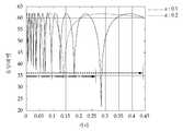
도 2는 레일리 거리 이후 구형 방사로 인한 음압 감소를 보여주기 위해 방사 중심축에서의 SPL(Sound Pressure Level) 값을 나타낸 그래프
도 3은 본 발명의 일실시예에 따른 초음파를 이용한 무선 전력 전송 시스템에서 방사판의 유효면적에 따른 레일리 거리 및 집중 빔 방사 형상의 변화를 나타낸 도면,
도 4는 본 발명에 따른 초음파 발생장치의 정렬을 위한 X, Y 및 팬/틸트 방향 제어를 보여주는 도면,
도 5는 본 발명에 따른 초음파 발생장치 내의 개별 초음파 소자의 작동에 의한 위치 및 방사 빔 형상 제어를 보여주는 도면,
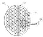
도 6은 본 발명에 따른 패드 형태의 초음파 발생장치에서 무선 에너지를 전송하는 예를 보여주는 도면,
도 7은 본 발명에 따른 초음파 발생장치가 이동성이 있는 전자장치에 무선 에너지를 전송하는 예를 보여주는 도면이다.FIG. 1 is a diagram for illustrating a Rayleigh distance and a radiation phenomenon according to frequency and effective area of an ultrasonic wave in a wireless power transmission system using an ultrasonic wave according to an embodiment of the present invention; FIG.
FIG. 2 is a graph showing the SPL (Sound Pressure Level) value at the radial center axis to show a reduction in sound pressure due to spherical radiation after the Rayleigh distance
FIG. 3 is a view showing a variation of a Rayleigh distance and a focused beam radial shape according to an effective area of a radiation plate in a wireless power transmission system using ultrasonic waves according to an embodiment of the present invention;
4 shows X, Y and pan / tilt direction controls for alignment of an ultrasonic generator according to the present invention,
5 is a view showing a position and a radiation beam shape control by operation of an individual ultrasonic element in the ultrasonic generator according to the present invention,
6 is a view showing an example of transmission of wireless energy in a pad type ultrasonic generator according to the present invention,
7 is a diagram illustrating an example in which the ultrasonic generator according to the present invention transmits radio energy to a mobile electronic device.
이하, 본 발명의 일실시예를 첨부된 도면들을 참조하여 상세히 설명한다. 또한, 본 발명을 설명함에 있어, 관련된 공지 구성 또는 기능에 대한 구체적인 설명이 본 발명의 요지를 흐릴 수 있다고 판단되는 경우에는 그 상세한 설명은 생략한다.Hereinafter, embodiments of the present invention will be described in detail with reference to the accompanying drawings. In the following description of the present invention, a detailed description of known functions and configurations incorporated herein will be omitted when it may make the subject matter of the present invention rather unclear.
도 1은 본 발명의 일실시예에 따른 초음파를 이용한 무선 전력 전송 시스템에서 초음파의 주파수 및 유효면적에 따른 레일리 거리(Rayleigh Distance) 및 방사 현상을 보여주기 위한 도면이고, 도 2는 레일리 거리 이후 구형 방사로 인한 음압 감소를 보여주기 위해 방사 중심축에서의 SPL(Sound Pressure Level) 값을 나타낸 그래프이다.FIG. 1 is a view showing a Rayleigh distance and a radial phenomenon depending on a frequency and an effective area of an ultrasonic wave in a wireless power transmission system using an ultrasonic wave according to an embodiment of the present invention. FIG. A graph showing SPL (Sound Pressure Level) values at the radial center axis to show a reduction in sound pressure due to radiation.
도 1을 참조하면, 초음파 발생장치(110)에서 발생되는 초음파의 방사 형상은 수학식 1에서와 같이 사용하는 주파수와 방사판의 면적, 매질에서의 음속에 의해 결정된다.Referring to FIG. 1, the radiation pattern of the ultrasonic wave generated by the

여기서, a는 방사판의 지름, c는 음압, P0는 기준점, z는 기준점에서의 거리, la는 음압의 감쇠 거리, ω, f는 동작 주파수를 나타낸다.Where a is the diameter of the radiating plate, c is the sound pressure, P0 is the reference point, z is the distance from the reference point, la is the attenuation distance of sound pressure, and ω and f are operating frequencies.
레일리 거리로 정의되는 구간은 근접장 구간이라고 하며, 이 구간에서 음압은 도 2에 도시된 바와 같이, 상쇄 보강 현상을 반복적으로 하게 되어, 초음파의 방사 형태는 점점 초점이 맞춰지듯이 집중적인 빔 형태를 가지게 된다. 그러나 레일리 거리를 벗어나면 도 1에 도시된 바와 같이, 음파는 구형 방사로 바뀌면서 퍼지는 빔 형상을 갖게 된다.The section defined by the Rayleigh distance is referred to as a near-field section. In this section, as shown in FIG. 2, the negative pressure repetitively performs the offset reinforcement phenomenon, so that the radiation pattern of the ultrasonic wave has a focused beam shape do. However, as shown in FIG. 1, when the Rayleigh distance is exceeded, the sound wave has a spreading beam shape while being converted into spherical radiation.
따라서, 빔이 퍼지기 전에 빔이 가장 집중되는 거리에 초음파 수신장치(120)를 위치시킨다면, 초음파 수신장치(120)는 가장 큰 초음파 에너지를 받을 수 있게 된다. 본 발명에서는 이러한 빔의 방사 특성을 이용하기 위해 초음파 발생장치(110)가 방사판의 유효면적을 변화시킴으로써 레일리 거리를 조절하고, 이를 통해 에너지 전달 효율이 극대화되는 방법을 제공한다. 여기서, 레일리 거리(D)는 수학식 2에 의해 정의된다.Therefore, if the ultrasonic

여기서, k = 2πf/c, f는 주파수, c는 음속, a는 방사판의 지름을 나타낸다.Here, k = 2πf / c, f is the frequency, c is the sound velocity, and a is the diameter of the radiation plate.
도 3은 본 발명의 일실시예에 따른 초음파를 이용한 무선 전력 전송 시스템에서 방사판의 유효면적에 따른 레일리 거리 및 집중 빔 방사 형상의 변화를 나타낸 도면이다.FIG. 3 is a diagram illustrating changes in the Rayleigh distance and the focused beam radial shape according to the effective area of the radiation plate in the wireless power transmission system using ultrasonic waves according to an embodiment of the present invention.
도 3을 참조하면, 본 발명에 따른 초음파를 이용한 무선 전력 전송 시스템은 초음파 발생장치(110) 및 초음파 수신장치(120) 등을 포함한다.Referring to FIG. 3, the wireless power transmission system using ultrasonic waves according to the present invention includes an
초음파 발생장치(110)는 전기 에너지를 초음파로 변환하여 초음파 수신장치(120)로 전송한다.The
본 발명에 따른 초음파 발생장치(110)는 복수의 초음파 소자(112a)가 배치된 방사판(112)을 구비하고, 초음파 수신장치(120)가 초음파의 구형 방사로 인한 퍼짐 효과가 가장 적은 위치에 위치하도록 초음파 발생장치(110)와 초음파 수신장치(120) 사이의 거리에 따라 복수의 초음파 소자(112a)를 온오프하여 방사판(112)의 유효면적을 조절한다. 여기서, 초음파 발생장치(110)는 초음파를 이용한 시간차나 위상차를 이용하여 초음파 발생장치(110)와 초음파 수신장치(120) 사이의 거리를 측정하거나 별도의 거리 센서를 이용하여 초음파 발생장치(110)와 초음파 수신장치(120) 사이의 거리를 측정할 수 있다. 또한, 복수의 초음파 소자(112a)는 대칭 구조를 갖는 원형 또는 다각형 형태로 배치될 수 있다.The ultrasonic
도 3에 도시된 바와 같이, 초음파 발생장치(110)와 초음파 수신장치(120) 사이의 거리에 따라 방사판(112)의 유효면적이 달라지는 것을 알 수 있다.As shown in FIG. 3, the effective area of the
도 4는 본 발명에 따른 초음파 발생장치의 정렬을 위한 X, Y 및 팬/틸트 방향 제어를 보여주는 도면이다.4 is a view showing X, Y and pan / tilt direction control for alignment of the ultrasonic generator according to the present invention.
도 4를 참조하면, 초음파 수신장치(120)를 포함하는 TV, 휴대단말 및 로봇 등의 전자기기가 초음파 발생장치(110)와 방향이 일치하지 않아 정렬이 필요할 때, 초음파 발생장치(110)는 수동 또는 모터를 이용하여, X, Y 및 팬/틸트 방향으로 조절될 수 있다. 예를 들면, 초음파 수신장치(120)를 내장한 TV를 벽에 걸어 사용할 경우, 초음파 수신장치(120)를 포함하는 TV의 위치에 따라 초음파 발생장치(110)를 X, Y 및 팬/틸트 방향으로 정렬한다.4, when an electronic device such as a TV, a portable terminal, or a robot including the
또한, 초음파 발생장치(110)는 초음파 수신장치(120)와 초음파 발생장치(110)가 정렬이 잘 되었을 때, LED나 소리 등을 통해 정렬 정도를 표시하는 표시 장치와 연동될 수도 있다.The ultrasonic
도 5는 본 발명에 따른 초음파 발생장치 내의 개별 초음파 소자의 작동에 의한 위치 및 방사 빔 형상 제어를 보여주는 도면이다.5 is a view showing a position and a radiation beam shape control by operation of an individual ultrasonic element in the ultrasonic generator according to the present invention.
도 5를 참조하면, 초음파 수신장치(120)를 포함하는 전자기기가 초음파 발생장치(110)와 옵셋을 두고 위치할 경우, 초음파 발생장치(110)는 초음파 수신장치(120)를 기준으로 중심점을 선택하고, 이 중심점에서 초음파 수신장치(120)와의 거리를 계산하여 초음파 발생장치(110)의 개별 초음파 소자(112a) 중 일부를 작동시켜 유효면적을 최적화한다.5, when the electronic apparatus including the
따라서, 초음파 수신장치(120)를 포함하는 로봇이나 단말기 등의 전자기기가 초음파 발생장치(110) 가까이에 오더라도 완벽히 중앙부에 정렬되지 않을 때, 상기 방법을 적용하면, 초음파 발생장치(110)와 초음파 수신장치(120) 사이에 최적화된 에너지 전달을 이룰 수 있다.Therefore, when the electronic device such as a robot or a terminal including the
도 6은 본 발명에 따른 패드 형태의 초음파 발생장치에서 무선 에너지를 전송하는 예를 보여주는 도면이다.6 is a diagram illustrating an example of transmission of wireless energy in a pad type ultrasonic generator according to the present invention.
도 6에 도시된 바와 같이, 본 발명에 따른 초음파 발생장치(110)는 패드 형태로 구성될 수 있고, 이 패드(610) 위에 초음파 수신장치(120)를 포함하는 전자장치(600)가 접촉되거나 일정 거리의 간격을 두고 위치하여 충전될 수 있다.6, the
따라서, 사용자가 패드(112) 위의 임의의 위치나 임의의 거리에 단말기나 전자장치(600)를 두더라도 개별 초음파 소자(612)의 작동에 의해 에너지 전달 효율을 최적화할 수 있다.Therefore, even if the user places the terminal or the
도 7은 본 발명에 따른 초음파 발생장치가 이동성이 있는 전자장치에 무선 에너지를 전송하는 예를 보여주는 도면이다.7 is a diagram illustrating an example in which the ultrasonic generator according to the present invention transmits radio energy to a mobile electronic device.
도 7을 참조하면, 초음파는 전달 매질이 공기뿐만 아니라 물이 될 수도 있다.Referring to FIG. 7, the ultrasonic wave may be a transfer medium as well as air.
본 발명에 따른 초음파 발생장치(110)는 물속에서 초음파 수신장치(120)를 포함하는 물고기 로봇 등과 같은 이동성이 있는 전자장치(700)에 에너지를 공급할 수 있다. 이동성이 있는 전자장치(700)는 에너지 전달 효율이 최대가 되는 초음파 발생장치(110) 근처로 이동하여 초음파 발생장치(110)로부터 에너지를 효과적으로 전달받을 수 있다. 이를 위해, 이동성이 있는 전자장치(700)는 초음파를 이용하여 초음파 발생장치(110)의 위치를 인식한다.The
본 발명의 명세서에 개시된 실시예들은 본 발명을 한정하는 것이 아니다. 본 발명의 범위는 아래의 특허청구범위에 의해 해석되어야 하며, 그와 균등한 범위 내에 있는 모든 기술도 본 발명의 범위에 포함되는 것으로 해석해야 할 것이다.The embodiments disclosed in the specification of the present invention do not limit the present invention. The scope of the present invention should be construed according to the following claims, and all the techniques within the scope of equivalents should be construed as being included in the scope of the present invention.
110: 초음파 발생장치 112: 방사판
112a: 초음파 소자 120: 초음파 수신장치110: ultrasonic wave generator 112: radiation plate
112a: Ultrasonic device 120: Ultrasonic receiving device
Claims (9)
Translated fromKorean상기 초음파를 수신하여 전기 에너지로 변환하는 초음파 수신장치;
를 포함하되,
상기 초음파 발생장치는 복수의 초음파 소자가 배치된 방사판을 구비하고, 상기 초음파 수신장치가 초음파의 구형 방사로 인한 퍼짐 효과가 가장 적은 위치에 위치하도록 상기 복수의 초음파 소자를 온오프하여 상기 방사판의 유효면적을 조절하고,
상기 복수의 초음파 소자 중 온(on) 상태를 갖는 초음파 소자는 상기 초음파를 방사하고, 오프(off) 상태를 갖는 초음파 소자는 초음파를 방사하지 않는 것을 특징으로 하는 초음파를 이용한 무선 전력 전송 시스템.An ultrasonic generator for converting electric energy into ultrasonic waves and transmitting the ultrasonic waves; And
An ultrasonic receiver for receiving the ultrasonic waves and converting the ultrasonic waves into electrical energy;
, ≪ / RTI &
Wherein the ultrasonic wave generator includes a radiation plate having a plurality of ultrasonic elements arranged therein, and the ultrasonic wave receiving apparatus turns on / off the plurality of ultrasonic wave elements so that the ultrasonic wave receiving apparatus is located at a position where the spreading effect of spherical radiation of the ultrasonic waves is minimized, To adjust the effective area of < RTI ID =
Wherein the ultrasonic device having an on state emits the ultrasonic wave and the ultrasonic device having an off state does not emit ultrasonic waves.
상기 초음파 발생장치는 자신과 상기 초음파 수신장치 사이의 거리에 따라 상기 방사판의 유효면적을 조절하는 것을 특징으로 하는 초음파를 이용한 무선 전력 전송 시스템.The method according to claim 1,
Wherein the ultrasonic generator adjusts an effective area of the radiation plate according to a distance between the ultrasonic generator and the ultrasonic receiver.
상기 초음파 발생장치는 초음파를 이용한 시간차나 위상차를 이용하여 상기 거리를 측정하는 것을 특징으로 하는 초음파를 이용한 무선 전력 전송 시스템.3. The method of claim 2,
Wherein the ultrasonic generator measures the distance using a time difference or a phase difference using ultrasonic waves.
상기 초음파 발생장치는 거리 센서를 이용하여 상기 거리를 측정하는 것을 특징으로 하는 초음파를 이용한 무선 전력 전송 시스템.3. The method of claim 2,
Wherein the ultrasonic generator measures the distance using a distance sensor.
상기 복수의 초음파 소자는 대칭 구조를 갖는 원형 또는 다각형 형태로 배치되는 것을 특징으로 하는 초음파를 이용한 무선 전력 전송 시스템.The method according to claim 1,
Wherein the plurality of ultrasonic devices are arranged in a circular or polygonal shape having a symmetrical structure.
상기 초음파 발생장치는 상기 초음파 수신장치를 기준으로 초음파가 방사되는 수직면에서 X, Y 또는 팬/틸트 방향으로 조절되는 것을 특징으로 하는 초음파를 이용한 무선 전력 전송 시스템.The method according to claim 1,
Wherein the ultrasonic generator is adjusted in X, Y, or pan / tilt directions on a vertical plane where ultrasonic waves are radiated with respect to the ultrasonic receiver.
상기 초음파 수신장치가 상기 초음파 발생장치와 옵셋을 두고 위치할 경우, 상기 초음파 발생장치는 상기 초음파 수신장치를 기준으로 중심점을 선택하고, 선택된 중심점에서 상기 초음파 수신장치와의 거리를 계산하며, 상기 복수의 초음파 소자들 중 일부를 온(on) 하여 상기 초음파 수신장치로의 상기 초음파가 전송되는 것을 특징으로 하는 무선 전력 전송 시스템.The method according to claim 1,
When the ultrasonic wave receiving apparatus is positioned offset from the ultrasonic wave generating apparatus, the ultrasonic wave generating apparatus selects a center point on the basis of the ultrasonic wave receiving apparatus, calculates a distance from the selected center point to the ultrasonic wave receiving apparatus, And the ultrasonic wave is transmitted to the ultrasonic wave receiving apparatus by turning on some of the ultrasonic wave elements of the ultrasonic wave receiving apparatus.
상기 초음파 발생장치는 패드 형태로 구성되고, 상기 초음파 수신장치는 패드와 접촉하거나 소정의 거리를 두고 위치하여 상기 패드로부터 초음파를 수신하는 것을 특징으로 하는 초음파를 이용한 무선 전력 전송 시스템.The method according to claim 1,
Wherein the ultrasonic wave generator is configured in the form of a pad, and the ultrasonic wave receiver is located at a predetermined distance in contact with the pad, and receives the ultrasonic wave from the pad.
상기 초음파 수신장치는 초음파를 이용하여 상기 초음파 발생장치의 위치를 인식하고, 상기 초음파 발생장치 근처의 초음파의 구형 방사로 인한 퍼짐 효과가 가장 적은 위치로 계속해서 이동하는 것을 특징으로 하는 초음파를 이용한 무선 전력 전송 시스템.The method according to claim 1,
Wherein the ultrasonic receiver recognizes the position of the ultrasonic generator using ultrasonic waves and continuously moves to a position where the spreading effect due to the spherical radiation of the ultrasonic waves in the vicinity of the ultrasonic generator is minimized. Power transmission system.
Priority Applications (2)
| Application Number | Priority Date | Filing Date | Title |
|---|---|---|---|
| KR1020100129920AKR101736284B1 (en) | 2010-12-17 | 2010-12-17 | System for Transferring Wireless Power Using Ultrasound |
| US13/310,550US9030917B2 (en) | 2010-12-17 | 2011-12-02 | System for transferring wireless power using ultrasonic wave |
Applications Claiming Priority (1)
| Application Number | Priority Date | Filing Date | Title |
|---|---|---|---|
| KR1020100129920AKR101736284B1 (en) | 2010-12-17 | 2010-12-17 | System for Transferring Wireless Power Using Ultrasound |
Publications (2)
| Publication Number | Publication Date |
|---|---|
| KR20120068334A KR20120068334A (en) | 2012-06-27 |
| KR101736284B1true KR101736284B1 (en) | 2017-05-16 |
Family
ID=46234248
Family Applications (1)
| Application Number | Title | Priority Date | Filing Date |
|---|---|---|---|
| KR1020100129920AExpired - Fee RelatedKR101736284B1 (en) | 2010-12-17 | 2010-12-17 | System for Transferring Wireless Power Using Ultrasound |
Country Status (2)
| Country | Link |
|---|---|
| US (1) | US9030917B2 (en) |
| KR (1) | KR101736284B1 (en) |
Families Citing this family (14)
| Publication number | Priority date | Publication date | Assignee | Title |
|---|---|---|---|---|
| US9094111B2 (en) | 2011-05-27 | 2015-07-28 | uBeam Inc. | Receiver transducer for wireless power transfer |
| US9722671B2 (en)* | 2011-05-27 | 2017-08-01 | uBeam Inc. | Oscillator circuits for wireless power transfer |
| US9831920B2 (en) | 2011-05-27 | 2017-11-28 | uBeam Inc. | Motion prediction for wireless power transfer |
| US9537322B2 (en) | 2011-05-27 | 2017-01-03 | uBeam Inc. | Sub-apertures with interleaved transmit elements for wireless power transfer |
| US10148131B2 (en) | 2011-05-27 | 2018-12-04 | uBeam Inc. | Power density control for wireless power transfer |
| US9819399B2 (en) | 2011-05-27 | 2017-11-14 | uBeam Inc. | Beam interaction control for wireless power transfer |
| WO2014066038A1 (en)* | 2012-10-26 | 2014-05-01 | Rensselaer Polytechinc Institute | Acoustic-electric channel construction and operation using adaptive transducer arrays |
| KR102005781B1 (en) | 2013-06-27 | 2019-07-31 | 한국전자통신연구원 | Device for transferring wireless power using ultrasound |
| US9620983B2 (en) | 2013-10-01 | 2017-04-11 | Intel Corporation | Ultrasonic universal wireless charging |
| FR3012923B1 (en)* | 2013-11-04 | 2017-09-01 | European Aeronautic Defence & Space Co Eads France | DEVICE FOR REMOTELY TRANSFERRING ENERGY BY ACOUSTIC WAVES TO A MOVING OBJECT |
| KR101810737B1 (en) | 2015-07-31 | 2017-12-19 | 울산과학기술원 | System for wireless power transmission and communication |
| KR102492190B1 (en) | 2016-01-11 | 2023-01-27 | 삼성전자주식회사 | Wireless power transmission device, a wireless charging system and method of controlling thereof |
| KR102328712B1 (en) | 2017-03-03 | 2021-11-22 | 삼성전자주식회사 | Transmitter for Transferring Wireless Power and Controlling Method Thereof |
| KR102433881B1 (en) | 2018-02-14 | 2022-08-19 | 삼성전자주식회사 | Electronic apparatus and method for controlling thereof |
Citations (1)
| Publication number | Priority date | Publication date | Assignee | Title |
|---|---|---|---|---|
| US20090028002A1 (en)* | 2007-07-25 | 2009-01-29 | Denso Corporation | Ultrasonic sensor |
Family Cites Families (11)
| Publication number | Priority date | Publication date | Assignee | Title |
|---|---|---|---|---|
| US4180791A (en)* | 1978-03-09 | 1979-12-25 | General Electric Company | Simplified sector scan ultrasonic imaging system |
| US6798716B1 (en) | 2003-06-19 | 2004-09-28 | Bc Systems, Inc. | System and method for wireless electrical power transmission |
| US7400253B2 (en) | 2005-08-04 | 2008-07-15 | Mhcmos, Llc | Harvesting ambient radio frequency electromagnetic energy for powering wireless electronic devices, sensors and sensor networks and applications thereof |
| US7728551B2 (en) | 2007-04-26 | 2010-06-01 | Visteon Global Technologies, Inc. | Wireless power transfer system |
| KR100911240B1 (en) | 2007-05-14 | 2009-08-06 | 가천의과학대학교 산학협력단 | Wireless Power Transmission Deep Brain Stimulation Device |
| US8446248B2 (en) | 2007-06-14 | 2013-05-21 | Omnilectric, Inc. | Wireless power transmission system |
| KR101425678B1 (en) | 2007-09-12 | 2014-07-31 | 엘지전자 주식회사 | Solid-state charging system |
| JP2009072652A (en) | 2007-09-19 | 2009-04-09 | Panasonic Corp | Ultrasonic power transmission device |
| KR20090098239A (en) | 2008-03-13 | 2009-09-17 | 주식회사 이엠에프 세이프티 | Wireless power transmission device and wireless charging system using same |
| US8552592B2 (en)* | 2008-09-27 | 2013-10-08 | Witricity Corporation | Wireless energy transfer with feedback control for lighting applications |
| US20100164433A1 (en) | 2008-12-30 | 2010-07-01 | Motorola, Inc. | Wireless Battery Charging Systems, Battery Systems and Charging Apparatus |
- 2010
- 2010-12-17KRKR1020100129920Apatent/KR101736284B1/ennot_activeExpired - Fee Related
- 2011
- 2011-12-02USUS13/310,550patent/US9030917B2/ennot_activeExpired - Fee Related
Patent Citations (1)
| Publication number | Priority date | Publication date | Assignee | Title |
|---|---|---|---|---|
| US20090028002A1 (en)* | 2007-07-25 | 2009-01-29 | Denso Corporation | Ultrasonic sensor |
Also Published As
| Publication number | Publication date |
|---|---|
| US20120155220A1 (en) | 2012-06-21 |
| KR20120068334A (en) | 2012-06-27 |
| US9030917B2 (en) | 2015-05-12 |
Similar Documents
| Publication | Publication Date | Title |
|---|---|---|
| KR101736284B1 (en) | System for Transferring Wireless Power Using Ultrasound | |
| US9419443B2 (en) | Transducer sound arrangement for pocket-forming | |
| US10468916B2 (en) | Charge level communications for wireless power transfer | |
| KR101145969B1 (en) | Wireless power transmission system | |
| US10742267B2 (en) | Beam interaction control for wireless power transfer | |
| KR102029919B1 (en) | Intelligent wireless power transmission device, charging system using intelligent wireless power and intelligent wireless power providing method | |
| WO2015038618A1 (en) | Wireless power supply for rescue devices | |
| US9722671B2 (en) | Oscillator circuits for wireless power transfer | |
| US20160268813A1 (en) | Sub-apertures with interleaved transmit elements for wireless power transfer | |
| KR20180034489A (en) | Motion estimation for wireless power transmission | |
| KR20180033221A (en) | Power density control for wireless power transmission | |
| CN211183544U (en) | Wireless remote directional power supply system |
Legal Events
| Date | Code | Title | Description |
|---|---|---|---|
| PA0109 | Patent application | St.27 status event code:A-0-1-A10-A12-nap-PA0109 | |
| PG1501 | Laying open of application | St.27 status event code:A-1-1-Q10-Q12-nap-PG1501 | |
| R17-X000 | Change to representative recorded | St.27 status event code:A-3-3-R10-R17-oth-X000 | |
| R17-X000 | Change to representative recorded | St.27 status event code:A-3-3-R10-R17-oth-X000 | |
| R17-X000 | Change to representative recorded | St.27 status event code:A-3-3-R10-R17-oth-X000 | |
| PN2301 | Change of applicant | St.27 status event code:A-3-3-R10-R13-asn-PN2301 St.27 status event code:A-3-3-R10-R11-asn-PN2301 | |
| A201 | Request for examination | ||
| PA0201 | Request for examination | St.27 status event code:A-1-2-D10-D11-exm-PA0201 | |
| P22-X000 | Classification modified | St.27 status event code:A-2-2-P10-P22-nap-X000 | |
| P22-X000 | Classification modified | St.27 status event code:A-2-2-P10-P22-nap-X000 | |
| E902 | Notification of reason for refusal | ||
| PE0902 | Notice of grounds for rejection | St.27 status event code:A-1-2-D10-D21-exm-PE0902 | |
| R17-X000 | Change to representative recorded | St.27 status event code:A-3-3-R10-R17-oth-X000 | |
| P11-X000 | Amendment of application requested | St.27 status event code:A-2-2-P10-P11-nap-X000 | |
| P13-X000 | Application amended | St.27 status event code:A-2-2-P10-P13-nap-X000 | |
| E701 | Decision to grant or registration of patent right | ||
| PE0701 | Decision of registration | St.27 status event code:A-1-2-D10-D22-exm-PE0701 | |
| GRNT | Written decision to grant | ||
| PR0701 | Registration of establishment | St.27 status event code:A-2-4-F10-F11-exm-PR0701 | |
| PR1002 | Payment of registration fee | St.27 status event code:A-2-2-U10-U11-oth-PR1002 Fee payment year number:1 | |
| PG1601 | Publication of registration | St.27 status event code:A-4-4-Q10-Q13-nap-PG1601 | |
| P22-X000 | Classification modified | St.27 status event code:A-4-4-P10-P22-nap-X000 | |
| P22-X000 | Classification modified | St.27 status event code:A-4-4-P10-P22-nap-X000 | |
| PC1903 | Unpaid annual fee | St.27 status event code:A-4-4-U10-U13-oth-PC1903 Not in force date:20200511 Payment event data comment text:Termination Category : DEFAULT_OF_REGISTRATION_FEE | |
| PC1903 | Unpaid annual fee | St.27 status event code:N-4-6-H10-H13-oth-PC1903 Ip right cessation event data comment text:Termination Category : DEFAULT_OF_REGISTRATION_FEE Not in force date:20200511 | |
| P22-X000 | Classification modified | St.27 status event code:A-4-4-P10-P22-nap-X000 |