KR101732648B1 - A Nozzle Assembly for Atomizing Liquid - Google Patents
A Nozzle Assembly for Atomizing LiquidDownload PDFInfo
- Publication number
- KR101732648B1 KR101732648B1KR1020140190767AKR20140190767AKR101732648B1KR 101732648 B1KR101732648 B1KR 101732648B1KR 1020140190767 AKR1020140190767 AKR 1020140190767AKR 20140190767 AKR20140190767 AKR 20140190767AKR 101732648 B1KR101732648 B1KR 101732648B1
- Authority
- KR
- South Korea
- Prior art keywords
- fluid
- vortex
- induction
- nozzle assembly
- unit
- Prior art date
- Legal status (The legal status is an assumption and is not a legal conclusion. Google has not performed a legal analysis and makes no representation as to the accuracy of the status listed.)
- Active
Links
- 239000007788liquidSubstances0.000titleabstractdescription41
- 239000012530fluidSubstances0.000claimsabstractdescription192
- 230000006698inductionEffects0.000claimsabstractdescription74
- 239000007921spraySubstances0.000claimsabstractdescription63
- 238000012546transferMethods0.000claimsabstractdescription26
- 238000005507sprayingMethods0.000claimsabstractdescription16
- 239000011859microparticleSubstances0.000claimsdescription2
- 239000007789gasSubstances0.000description24
- 239000010419fine particleSubstances0.000description19
- 238000002347injectionMethods0.000description10
- 239000007924injectionSubstances0.000description10
- 239000013256coordination polymerSubstances0.000description7
- 238000000576coating methodMethods0.000description6
- 238000004891communicationMethods0.000description5
- 238000003780insertionMethods0.000description5
- 230000037431insertionEffects0.000description5
- 230000001954sterilising effectEffects0.000description5
- 230000015572biosynthetic processEffects0.000description4
- 239000011248coating agentSubstances0.000description4
- 238000000926separation methodMethods0.000description4
- 238000004659sterilization and disinfectionMethods0.000description4
- 238000004887air purificationMethods0.000description3
- 238000004332deodorizationMethods0.000description3
- 238000002156mixingMethods0.000description3
- 239000002245particleSubstances0.000description3
- XLYOFNOQVPJJNP-UHFFFAOYSA-NwaterSubstancesOXLYOFNOQVPJJNP-UHFFFAOYSA-N0.000description3
- VYZAMTAEIAYCRO-UHFFFAOYSA-NChromiumChemical compound[Cr]VYZAMTAEIAYCRO-UHFFFAOYSA-N0.000description2
- -1NO xInorganic materials0.000description2
- CBENFWSGALASAD-UHFFFAOYSA-NOzoneChemical compound[O-][O+]=OCBENFWSGALASAD-UHFFFAOYSA-N0.000description2
- 229910005965SO 2Inorganic materials0.000description2
- 229910052785arsenicInorganic materials0.000description2
- RQNWIZPPADIBDY-UHFFFAOYSA-Narsenic atomChemical compound[As]RQNWIZPPADIBDY-UHFFFAOYSA-N0.000description2
- 239000003795chemical substances by applicationSubstances0.000description2
- 229910052804chromiumInorganic materials0.000description2
- 239000011651chromiumSubstances0.000description2
- 238000002485combustion reactionMethods0.000description2
- 239000000356contaminantSubstances0.000description2
- 238000001816coolingMethods0.000description2
- 230000008878couplingEffects0.000description2
- 238000010168coupling processMethods0.000description2
- 238000005859coupling reactionMethods0.000description2
- 239000000428dustSubstances0.000description2
- 229910001385heavy metalInorganic materials0.000description2
- QSHDDOUJBYECFT-UHFFFAOYSA-NmercuryChemical compound[Hg]QSHDDOUJBYECFT-UHFFFAOYSA-N0.000description2
- 229910052753mercuryInorganic materials0.000description2
- 230000001473noxious effectEffects0.000description2
- 230000002093peripheral effectEffects0.000description2
- 230000000704physical effectEffects0.000description2
- 239000011163secondary particleSubstances0.000description2
- 239000004065semiconductorSubstances0.000description2
- 125000006850spacer groupChemical group0.000description2
- 230000004308accommodationEffects0.000description1
- 230000006835compressionEffects0.000description1
- 238000007906compressionMethods0.000description1
- 230000003247decreasing effectEffects0.000description1
- 238000013461designMethods0.000description1
- 238000005516engineering processMethods0.000description1
- 238000004519manufacturing processMethods0.000description1
- 239000000463materialSubstances0.000description1
- 238000012986modificationMethods0.000description1
- 230000004048modificationEffects0.000description1
- 230000000149penetrating effectEffects0.000description1
- 238000011160researchMethods0.000description1
- 238000007789sealingMethods0.000description1
- 238000010008shearingMethods0.000description1
- 239000007787solidSubstances0.000description1
Images


Classifications
- B—PERFORMING OPERATIONS; TRANSPORTING
- B05—SPRAYING OR ATOMISING IN GENERAL; APPLYING FLUENT MATERIALS TO SURFACES, IN GENERAL
- B05B—SPRAYING APPARATUS; ATOMISING APPARATUS; NOZZLES
- B05B7/00—Spraying apparatus for discharge of liquids or other fluent materials from two or more sources, e.g. of liquid and air, of powder and gas
- B05B7/02—Spray pistols; Apparatus for discharge
- B05B7/04—Spray pistols; Apparatus for discharge with arrangements for mixing liquids or other fluent materials before discharge
- B05B7/0416—Spray pistols; Apparatus for discharge with arrangements for mixing liquids or other fluent materials before discharge with arrangements for mixing one gas and one liquid
- B—PERFORMING OPERATIONS; TRANSPORTING
- B01—PHYSICAL OR CHEMICAL PROCESSES OR APPARATUS IN GENERAL
- B01D—SEPARATION
- B01D47/00—Separating dispersed particles from gases, air or vapours by liquid as separating agent
- B01D47/06—Spray cleaning
- B—PERFORMING OPERATIONS; TRANSPORTING
- B05—SPRAYING OR ATOMISING IN GENERAL; APPLYING FLUENT MATERIALS TO SURFACES, IN GENERAL
- B05B—SPRAYING APPARATUS; ATOMISING APPARATUS; NOZZLES
- B05B1/00—Nozzles, spray heads or other outlets, with or without auxiliary devices such as valves, heating means
- B05B1/02—Nozzles, spray heads or other outlets, with or without auxiliary devices such as valves, heating means designed to produce a jet, spray, or other discharge of particular shape or nature, e.g. in single drops, or having an outlet of particular shape
- B05B1/10—Nozzles, spray heads or other outlets, with or without auxiliary devices such as valves, heating means designed to produce a jet, spray, or other discharge of particular shape or nature, e.g. in single drops, or having an outlet of particular shape in the form of a fine jet, e.g. for use in wind-screen washers
- B—PERFORMING OPERATIONS; TRANSPORTING
- B05—SPRAYING OR ATOMISING IN GENERAL; APPLYING FLUENT MATERIALS TO SURFACES, IN GENERAL
- B05B—SPRAYING APPARATUS; ATOMISING APPARATUS; NOZZLES
- B05B1/00—Nozzles, spray heads or other outlets, with or without auxiliary devices such as valves, heating means
- B05B1/34—Nozzles, spray heads or other outlets, with or without auxiliary devices such as valves, heating means designed to influence the nature of flow of the liquid or other fluent material, e.g. to produce swirl
- B05B1/3405—Nozzles, spray heads or other outlets, with or without auxiliary devices such as valves, heating means designed to influence the nature of flow of the liquid or other fluent material, e.g. to produce swirl to produce swirl
Landscapes
- Chemical & Material Sciences (AREA)
- Chemical Kinetics & Catalysis (AREA)
- Nozzles (AREA)
Abstract
Translated fromKoreanDescription
Translated fromKorean본 발명은 다수 유체 미립자 분무용 노즐 어셈블리에 관한 것이고, 구체적으로 적어도 하나의 기체 및 적어도 하나의 액체를 미립자 형태로 동시에 분무하는 것이 가능한 다수 유체 미립자 분무용 노즐 어셈블리에 관한 것이다.The present invention relates to a multiple fluid particulate spray nozzle assembly, and more particularly to a multiple fluid particulate spray nozzle assembly capable of simultaneously atomizing at least one gas and at least one liquid in particulate form.
액체 또는 기체를 고속으로 자유 공간에 분출되도록 유로의 끝에 형성되는 관을 노즐이라고 한다. 노즐은 고체, 액체 및 기체를 정해진 양으로 특정 부위에 도달되도록 설계가 되고 다양한 구조를 가지는 노즐이 이 분야에서 공지되어 있다. 예를 들어 반도체, 디스플레이 또는 모바일 제품의 생산 공정에서 표면 코팅을 위하여 노즐이 적용될 수 있다. 반도체, 디스플레이 또는 모바일 제품은 진화하는 소재 분야의 기술과 융합되어 비-평면, 비구면 또는 3차원 형상으로 점차적으로 변화하고 있다. 이와 같은 제품의 표면 코팅 과정에서 요구되는 수준의 코팅 면을 얻기 위하여 분출 압력 또는 분출 액량이 정확하게 제어될 필요가 있다. 또한 코팅 과정에서 미립자의 크기가 코팅 품질에 영향을 미치는 주요한 인자가 될 수 있다. 예를 들어 20 이하의 미립자의 형성을 위하여 노즐 직경이 이에 대응되도록 조절될 필요가 있다. 그러나 노즐 직경이 작아지면 토출 압력이 작아질 수 있고 그리고 노즐 길이가 제한될 수 있다. 이와 같은 문제의 해결을 위하여 요구되는 품질을 가지면서 구조적 안정성을 가진 노즐이 요구된다.The tube formed at the end of the flow path is referred to as a nozzle so that liquid or gas is ejected at high speed into the free space. Nozzles are known in the art to be designed to reach specific areas of solids, liquids, and gases in defined amounts and have various structures. For example, nozzles can be applied for surface coating in production processes of semiconductors, displays or mobile products. Semiconductors, displays, or mobile products are gradually changing to non-planar, aspherical, or three-dimensional shapes, fused with evolving technology in the field of materials. It is necessary that the ejection pressure or the amount of ejected liquid be accurately controlled in order to obtain a level of the coating surface required in the surface coating process of such a product. Also, the size of the particles in the coating process can be a major factor affecting the coating quality. For example, in order to form fine particles of 20 or less, it is necessary to adjust the nozzle diameter so as to correspond thereto. However, the smaller the nozzle diameter, the smaller the discharge pressure and the nozzle length may be limited. In order to solve such a problem, there is a demand for a nozzle having a required quality and a structural stability.
노즐과 관련된 선행기술로 노즐과 관련된 선행기술로 공개특허번호 제2005-0117416호 2유체 분사 노즐이 있다. 상기 선행기술은 미세하고 균일한 크기의 분무를 위하여 액체가 고정 벽면과 마찰에 의한 속도 구배를 이루지 않도록 액체와 고정 벽과 접촉을 회피할 수 있도록 하는 구조를 가진 2유체 분사 노즐에 관하여 개시한다. 상기 선행기술은 2유체 분사 노즐에 있어서, 하단부에 다수의 혼합구가 형성된 몸체를 이루는 하우징; 및 상기 하우징의 중심부에 내삽되어 하우징과 사이에 스페이서를 형성하고, 상기 스페이서에 압축 기체를 공급하는 기체 주입구와 상기 혼합구와 동일 축에 있고, 상기 혼합구로 액체를 공급하는 액체 주입구를 가지는 내부 구조체를 포함하는 2유체 분사 노즐에 대하여 개시한다. 제시된 선행기술은 분사 노즐에 이격 공간(spacer)이 형성되는 것에 의하여 분무 입자의 불균일성이 해소될 수 있지만 분사 범위가 작아질 수 있고 분사 노즐의 막힘 현상이 발생될 수 있다는 단점을 가진다.Prior Art No. 2005-0117416 discloses a two-fluid spray nozzle as a prior art related to a nozzle with respect to a nozzle. The prior art discloses a two fluid injection nozzle having a structure that allows the liquid to avoid contact with liquid and fixed walls so that the liquid does not have a velocity gradient due to friction with the fixed wall surface for fine and uniform sized spray. The prior art is a two fluid injection nozzle comprising: a housing constituting a body having a plurality of mixing holes formed at a lower end thereof; And an inner structure having a gas injection port which is inserted into a central portion of the housing to form a spacer between the housing and the compressor, and a liquid injection port which is coaxial with the mixing port and supplies the liquid to the mixing port, The present invention relates to a two-fluid injection nozzle including a plurality of fluid injection nozzles. The proposed prior art has a disadvantage in that the spacing of the spraying nozzles can be reduced by forming spacers in the spraying nozzles, but the spraying range can be reduced and clogging of the spraying nozzles can occur.
노즐과 관련된 다른 선행기술로 등록특허번호 제1363021호 분사 노즐이 있다. 상기 선행기술은 낮은 압력에서 미립자를 생성하고 저비산 에어커튼 분사 기능을 가지는 분사 노즐을 제공하기 위한 것으로 제1 유체를 공급하는 제1 통로와 제2 유체를 공급하는 제2 통로 및 제3 유체를 공급하는 제3 통로를 가지는 매니폴드, 상기 매니폴드에 결합되어 내측으로 상기 제1 통로에 연결되어 제1 토출구를 형성하고, 상기 제1 토출구 외측으로 제1 와류 홈으로 제2 통로에 연결되는 제1 와류자, 상기 제1 와류자를 수용하여 상기 매니폴드에 결합되어 내측으로 상기 제2 통로에 연결되어 제2 토출구를 형성하고, 상기 제2 토출구 외측으로 제2 와류 홈으로 상기 제3 통로에 연결되는 제2 와류자 및 상기 제2 와류 홈에 접촉되어 상기 제2 와류자를 수용하여 상기 매니폴드에 결합되어 내측으로 상기 제3 통로에 연결되어 제3 토출구를 형성하는 토출 캡을 포함하는 분사 노즐에 대하여 개시한다.Another prior art related to nozzles is the No. 1363021 spray nozzle. The prior art is to provide a spray nozzle for generating particulates at low pressure and having a low scattering air curtain jetting function, comprising a first passage for supplying a first fluid, a second passage for supplying a second fluid, A first passage connected to the manifold and connected to the first passage to form a first discharge port and a second passage connected to the second passage with a first vortex groove outside the first discharge port; A first vortex, which is coupled to the manifold to receive the first vortex and connected to the second passage inward to form a second discharge port, and connected to the third passage with a second vortex groove outside the second discharge port And a discharge port which is in contact with the second vortex groove to receive the second vortex element and is connected to the manifold and connected to the third passage to form a third discharge port, Disclosed is an injection nozzle including a cap.
제시된 선행기술은 분사 노즐의 막힘 현상 해소, 분사 미립자의 균일성 및 낮은 압력의 분사 구조를 가지지만 노즐의 직경 또는 노즐 길이가 제한될 수 있다는 단점을 가진다. 또한 상기 선행기술 또는 공지된 노즐은 높은 압력에서 작동되고, 균일한 미립자의 형성이 어렵고 이와 동시에 않은 유량의 액체의 미립화가 어렵다는 단점을 가진다. 다른 한편으로 노즐 어셈블리를 통하여 다수의 유체가 분무될 필요가 있다. 예를 들어 공기 정화를 위하여 살균수가 다른 유체와 함께 노즐 어셈블리에 의하여 분무될 필요가 있다. 선행기술은 이와 같이 다수의 유체 분무가 어렵다는 단점을 가진다.The proposed prior art has the disadvantage that the clogging phenomenon of the injection nozzle is solved, the uniformity of the sprayed fine particles and the injection structure of low pressure, but the diameter of the nozzle or the nozzle length can be limited. Further, the prior art or known nozzles are operated at a high pressure, and it is difficult to form uniform fine particles, and at the same time, it is difficult to atomize the liquid at a non-flow rate. On the other hand, a large number of fluids need to be sprayed through the nozzle assembly. For example, sterilization water needs to be sprayed by the nozzle assembly with other fluids for air purification. The prior art has the disadvantage that it is difficult to spray a large number of fluids.
본 발명은 공지된 노즐이 가진 문제점을 해결하기 위한 것으로 아래와 같은 목적을 가진다.The present invention is intended to solve the problems of known nozzles and has the following purpose.
본 발명의 목적은 낮은 압력에서 작동이 가능하면서 균일한 미립자가 형성되도록 하고 이와 동시에 다수의 유체의 분무가 가능하도록 하는 다수 유체 미립자 분무용 노즐 어셈블리를 제공하는 것이다.It is an object of the present invention to provide a nozzle assembly for multi-fluid particulate spray which is capable of operating at low pressures while allowing uniform microparticles to be formed and at the same time enabling the spraying of multiple fluids.
본 발명의 적절한 실시 형태에 따르면, 적어도 2개의 유입 통로가 형성된 유체 공급 몸체; 유체 공급 몸체에 결합되고, 유체 이송이 가능한 공급 경로가 형성된 유체 유도 유닛; 유체 유도 유닛에 결합되고 상기 적어도 2개의 유입 통로로부터 유입된 유체를 유도하기 위한 통로가 형성된 유체 이송 유닛; 유체 이송 유닛으로부터 유도되는 유체로부터 와류를 형성하는 와류 발생기; 및 유체 유도 유닛으로부터 이송된 유체 및 와류 발생기에서 발생된 와류를 분무시키는 분무 캡을 포함한다.According to a preferred embodiment of the present invention, there is provided a fluid supply device comprising: a fluid supply body formed with at least two inflow passages; A fluid induction unit coupled to the fluid supply body and having a supply path through which fluid can be transferred; A fluid delivery unit coupled to the fluid induction unit and having a passage for guiding the fluid introduced from the at least two inflow passages; A vortex generator that forms a vortex from a fluid derived from the fluid transfer unit; And a spray cap for spraying a fluid transferred from the fluid induction unit and a vortex generated in the vortex generator.
본 발명의 다른 적절한 실시 형태에 따르면, 유체 공급 몸체로부터 공급되는 유체를 유체 이송 유닛으로 유도하기 위한 연결 패드를 더 포함한다.According to another preferred embodiment of the present invention, further comprising a connection pad for leading the fluid supplied from the fluid supply body to the fluid transfer unit.
본 발명의 또 다른 적절한 실시 형태에 따르면, 상기 적어도 하나의 유입 통로 중 하나의 유입 통로를 유체 이송 유닛과 연결하는 제1 연결 통로와 다른 하나의 유입 통로와 연결되도록 유체 이송 유닛의 둘레에 형성된 제2 연결 통로를 더 포함한다.According to another preferred embodiment of the present invention, there is provided a fluid communication system comprising: a fluid communication unit for fluid communication between a fluid communication unit and a fluid communication unit, 2 connecting passages.
본 발명의 또 다른 적절한 실시 형태에 따르면, 상기 제2 연결 통로에 와류 발생기로 연결되도록 와류 홀이 형성된다.According to another preferred embodiment of the present invention, a vortex hole is formed so as to be connected to the vortex generator in the second connection passage.
본 발명의 또 다른 적절한 실시 형태에 따르면, 상기 분무 캡의 중앙에 형성된 분무 홀을 더 포함하고, 상기 분무 홀은 둘레 면을 따라 환형으로 상기 2개의 유입 통로로부터 공급된 유체가 함께 분무되도록 형성된다.According to another preferred embodiment of the present invention, there is further provided a spray hole formed in the center of the spray cap, wherein the spray hole is formed such that the fluid supplied from the two inlet passages is sprayed together in an annular shape along the circumferential surface .
본 발명의 또 다른 적절한 실시 형태에 따르면, 상기 와류 발생기에서 유체는 경사면을 따라 유도된다.According to another preferred embodiment of the present invention, the fluid in the vortex generator is directed along a slope.
본 발명에 따른 노즐 어셈블리는 일차로 와류 발생기에서 액체와 기체의 충돌에 의하여 미립자를 형성하고, 다시 환형 통로로 분사되면서 이차적으로 미립자를 형성시킨다. 이로 인하여 많은 공급량의 액체에 대한 균일한 미립자 형성이 가능하도록 하면서 이와 동시에 낮은 압력으로 미립자가 형성될 수 있도록 한다. 또한 본 발명에 따른 노즐 어셈블리는 고온 연소로의 가스 냉각용 및 공기 조화기용 노즐로 적용되어 질소산화물(NOX), SO2, 수은, 비소 또는 크롬과 같은 중금속의 제거가 가능하도록 한다. 추가로 본 발명에 따른 노즐 어셈블리는 작업장 또는 공장 설비 내에 설치되어 유해 가스의 제거에 적용될 수 있도록 하면서 오존 발생을 위한 액체 또는 탈취 제거를 위한 제제가 혼합된 액체의 분무를 위한 시스템에 적용될 수 있도록 한다. 추가로 본 발명에 따른 노즐 어셈블리는 예를 들어 살균을 위한 유체 또는 오존수와 같은 것이 다른 유체와 함께 동시에 분무되는 것이 가능하도록 하는 것에 의하여 공기 정화 또는 오염 물질의 제거 효과가 상승되도록 한다.The nozzle assembly according to the present invention primarily forms fine particles by collision of liquid and gas in a vortex generator, and forms secondary particles while being injected into an annular passage again. This allows fine particles to be formed at low pressure while simultaneously allowing the formation of fine particles for a large volume of liquid. Also, the nozzle assembly according to the present invention is applied as a nozzle for a gas cooling furnace and an air conditioner in a high-temperature combustion furnace to remove heavy metals such as NOx , SO2 , mercury, arsenic or chromium. In addition, the nozzle assembly according to the present invention can be applied to a system for spraying a liquid mixed with an agent for ozone generation or deodorization, while being installed in a workplace or a plant facility so as to be applicable to the removal of noxious gases . In addition, the nozzle assembly according to the present invention allows air purification or removal of contaminants to be enhanced, for example by allowing fluid such as sterilization or ozonated water to be sprayed simultaneously with other fluids.
도 1a 및 도 1b는 본 발명에 따른 다수 유체 미립자 분무용 노즐 어셈블리의 실시 예를 도시한 것이다.
도 2a 및 도 2b는 본 발명에 따른 노즐 어셈블리에 적용되는 각각의 장치의 실시 예를 도시한 것이다.
도 3a 및 도 3b는 본 발명에 따른 노즐 어셈블리의 작동 과정의 실시 예를 도시한 것이다.FIGS. 1A and 1B illustrate an embodiment of a multiple fluid particulate spray nozzle assembly according to the present invention.
2A and 2B illustrate an embodiment of each device applied to a nozzle assembly according to the present invention.
FIGS. 3A and 3B illustrate an operation of the nozzle assembly according to the present invention.
아래에서 본 발명은 첨부된 도면에 제시된 실시 예를 참조하여 상세하게 설명이 되지만 실시 예는 본 발명의 명확한 이해를 위한 것으로 본 발명은 이에 제한되지 않는다. 아래의 설명에서 서로 다른 도면에서 동일한 도면 부호를 가지는 구성요소는 유사한 기능을 가지므로 발명의 이해를 위하여 필요하지 않는다면 반복하여 설명이 되지 않으며 공지의 구성요소는 간략하게 설명이 되거나 생략이 되지만 본 발명의 실시 예에서 제외되는 것으로 이해되지 않아야 한다.DETAILED DESCRIPTION OF THE PREFERRED EMBODIMENTS Hereinafter, the present invention will be described in detail with reference to the embodiments shown in the accompanying drawings, but the present invention is not limited thereto. In the following description, components having the same reference numerals in different drawings have similar functions, so that they will not be described repeatedly unless necessary for an understanding of the invention, and the known components will be briefly described or omitted. However, It should not be understood as being excluded from the embodiment of Fig.
도 1a 및 도 1b는 본 발명에 따른 다수 유체 미립자 분무용 노즐 어셈블리의 실시 예를 도시한 것이다.FIGS. 1A and 1B illustrate an embodiment of a multiple fluid particulate spray nozzle assembly according to the present invention.
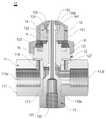
도 1a 및 도 1b를 참조하면, 본 발명에 따른 다수 유체 미립자 분무용 노즐 어셈블리(10)는 적어도 2개의 유입 통로(112a, 112b)가 형성된 유체 공급 몸체 (11); 유체 공급 몸체 (11)에 결합되고, 유체 이송이 가능한 공급 경로가 형성된 유체 유도 유닛(12); 유체 유도 유닛(12)에 결합되고 상기 적어도 2개의 유입 통로(112a, 112b)로부터 유입된 유체를 유도하기 위한 통로가 형성된 유체 이송 유닛(13); 유체 이송 유닛(13)으로부터 유도되는 유체로부터 와류를 형성하는 와류 발생기(14); 및 유체 유도 유닛(12)으로부터 이송된 유체 및 와류 발생기(14)에서 발생된 와류를 분무시키는 분무 캡(15)을 포함한다.Referring to FIGS. 1A and 1B, a multiple fluid particle
본 발명에 따른 노즐 어셈블리(10)은 액체를 미립자 형태로 분무시켜 공기를 정화하는 임의의 공기 조화기, 집진 장치, 집진 필터 또는 공기 순환 장치와 같은 장치에 적용되거나 이와 같은 장치와 함께 사용될 수 있다. 또한 본 발명에 따른 노즐 어셈블리(10)는 적절한 설계 변경에 의하여 코팅 또는 접착을 위한 분배기(dispenser)와 같은 장치에 적용될 수 있다. 그러므로 본 발명에 따른 노즐 어셈블리(10)는 적용 분야에 의하여 제한되지 않는다.The
본 발명에 따른 노즐 어셈블리(10)를 통하여 분무되는 액체는 다양한 종류의 살균 또는 탈취를 위한 성분을 포함할 수 있다. 또한 노즐 어셈블리(10)를 통하여 공급되는 기체는 별도의 공급 장치를 통하여 공급되거나 순환이 되는 실내 또는 실외 공기의 일부가 될 수 있다. 이와 같은 본 발명에 따른 노즐 어셈블리(10)는 별도로 설치되거나 다른 장치에 함께 사용될 수 있고, 다양한 종류의 액체 분무에 적용될 수 있고 분무되는 유체의 종류에 의하여 제한되지 않는다.The liquid sprayed through the
유체 공급 몸체(11)는 전체적으로 원통 형상이 되는 공급 몸체(111), 공급 몸체(111)의 양쪽에 형성된 제1, 2 유입 통로(112a, 112b) 및 공급 몸체(111)의 중앙 부분에 형성된 체결 공(113)으로 이루어질 수 있다. 이와 같이 유체 공급 몸체(11)는 T형 연결 밸브 또는 커넥터 구조를 가질 수 있지만 유입 통로(112a, 112b) 및 체결 공(113)은 다양한 구조로 형성될 수 있고 본 발명은 제시된 실시 예에 제한되지 않는다. 제1, 2 유입 통로(112a, 112b)를 통하여 기체와 같은 제1 유체와 액체와 같은 서로 다른 물리적 성질을 가진 제2 유체가 유입될 수 있다. 그리고 체결 공(113)에 유체 이송 유닛(13)이 연결될 수 있다. 체결 공(113)을 통하여 예를 들어 유입 통로(112a, 112b)를 통하여 공급되는 유체와 다른 특성을 가진 제3 유체가 공급될 수 있다. 제3 유체는 분무되는 또는 코팅이 되는 주요 성분이 될 수 있고 유체 이송 유닛(13)으로 공급되는 제3 유체는 독립적인 경로를 경유하여 분무 캡(15)에 형성된 분무 홀(152)로 유도될 수 있다. 도 1a 및 도 1b에 제시된 실시 예에서 제1 유체는 기체, 제2 유체는 액체 그리고 제3 유체는 액체가 될 수 있고, 제2 유체는 예를 들어 살균 성분을 포함하는 액체 또는 제3 유체의 물리적 특성을 향상시키기 위한 액체가 될 수 있다. 다만 다양한 형태의 유체가 제1, 2 유입 통로(112a, 112b) 또는 유체 이송 유닛(13)을 통하여 공급될 수 있고, 본 발명은 제시된 실시 예는 제한되지 않는다.The
제1 유입 통로(112a)에 제1 연결 통로(114)가 형성되어 제1 유입 통로(112a)를 통하여 유입되는 유체를 유체 유도 유닛(12)으로 유도할 수 있다. 또한 제2 유입 통로(112b)는 유체 유도 유닛(12)의 내부에 형성된 제2 연결 통로(123)와 연결될 수 있다.The
제1 연결 통로(114)는 제1 유입 통로(112a)로부터 둘레 면에 수직으로 연장되어 공급 몸체(111)의 외부를 경유하여 유체 유도 유닛(12)으로 연결되도록 형성될 수 있다. 그리고 제2 유입 통로(112b)의 끝 부분은 유체 유도 유닛(12)의 아래쪽 부분에 형성된 유도 부분(127)과 연결되고, 제2 연결 통로(123)는 유체 유도 유닛(12)의 중앙 부분 또는 유체 이송 유닛(13)의 둘레 면을 따라 형성될 수 있다. 이와 같은 경로 형성에 의하여 제1 유체는 유체 유도 유닛(12)의 둘레 면을 따라 형성된 경로를 통하여, 그리고 제2 유체는 유체 유도 유닛(12)을 관통하는 유체 이송 유닛(13)의 둘레 또는 유체 유도 유닛(12)의 중앙 부분을 따라 형성된 경로를 따라 분무 캡(15)으로 유도될 수 있다. 그리고 제1, 2 유체와 유체 이송 유닛(13)을 따라 이송되는 제3 유체는 각각 독립된 이송 경로를 따라 분무 홀(152)로 유도될 수 있다.The
유체 유도 유닛(12)은 중앙 부분에 관통 경로(CP)가 형성된 유도 몸체(121), 유도 몸체(121)에 형성된 유도 경로(122), 관통 경로(CP)를 따라 형성된 제2 연결 통로(123), 제2 연결 통로(123)로부터 유도되는 제2 유체를 와류 발생기(14)로 유도하는 와류 홀(124) 및 와류 홀(124)의 위쪽에 형성되는 유도 팁(125)으로 이루어질 수 있다. 그리고 공급 몸체(111)와 유체 유도 유닛(12) 사이에 연결 패드(16)가 배치되어 제1 연결 통로(114)로 이송되는 제1 유체를 유체 유도 유닛(12)으로 유도할 수 있다.The
유도 몸체(121)는 공급 몸체(111)와 결합될 수 있는 다양한 형상을 가질 수 있고, 중앙 부분에 유체 이송 유닛(13)의 위쪽 부분이 결합되는 관통 경로(CP)가 형성될 수 있다. 관통 경로(CP)는 유도 몸체(121)의 아래쪽 부분으로부터 위쪽 부분을 관통하여 구조로 형성되어 분무 홀(152)과 연결될 수 있다. 관통 경로(CP)를 따라 제2 연결 통로(123)가 형성될 수 있다. 제2 연결 통로(123)는 유도 몸체(121)에 형성되거나 또는 관통 경로(CP)와 유체 이송 유닛(13) 사이의 결합 간격을 이용하여 형성될 수 있다. 제2 연결 통로(123)의 위쪽 부분에 제2 유체를 와류 발생기(14)로 유도하기 위한 와류 홀(124)이 형성될 수 있다. 와류 홀(124)은 제2 연결 통로(123)의 길이 방향에 대하여 수직이 되는 방향으로 형성될 수 있다. 와류 홀(124)의 위쪽 부분에 형성되는 유도 팁(125)은 외부 둘레 면이 경사면을 형성하도록 만들어질 수 있지만 이에 제한되지 않고 와류 발생기(14) 내부의 기체를 유도할 수 있는 다양한 구조를 가질 수 있다. 유도 팁(125)을 끝 부분을 관통하여 유체 이송 유닛(13)의 끝 부분이 배치될 수 있다.The
제3 유체의 이송을 위한 유체 이송 유닛(13)은 공급 몸체(111)에 결합되는 이송 몸체(131), 이송 몸체(131)의 내부에 형성된 공급 커넥터(132), 공급 커넥터(132)와 연결되어 제3 유체의 공급 유로를 형성하는 제1, 2 공급 경로(133a, 133b)로 이루어질 수 있다. 공급 커넥터(132)는 제3 유체의 공급을 위한 다양한 공급 유닛에 연결될 수 있는 임의의 구조를 가질 수 있다. 그리고 제1, 2 공급 경로(133a, 133b)는 서로 다른 단면적을 가지면서 연장되는 튜브 형상이 될 수 있다. 예를 들어 제1 공급 경로(133a)는 공급 커넥터(132)에 대응되는 단면적을 가지고, 제2 공급 경로(133b)는 분무 홀(152)의 직경. 분무되어야 할 유체의 공급 양 또는 기체와 같은 제1 유체의 공급 압력에 기초하여 결정될 수 있다. 구체적으로 제2 공급 경로(133b)는 제1 공급 경로(133a)에 비하여 충분히 작은 직경을 가지면서 일정 길이로 분무 홀(152)에 이르도록 연장될 수 있다. 제2 공급 경로(133b)는 위에서 설명된 관통 경로(CP)에 배치될 수 있고 분무 팁을 관통하여 분무 홀(152)에 이를 수 있다.The
와류 발생기(14)는 속이 빈 원통 형상이 되면서 아래쪽 면의 중앙 부분에 삽입 홀(141)이 형성되고 그리고 위쪽 면이 개방된 원통 형상이 될 수 있다. 와류 발생기(14)의 둘레 면을 따라 유체 유도 경로(143)가 형성될 수 있고 유체 유도 경로(143)는 유도 경로(122)와 연결될 수 있다. 제1 유체는 제1 연결 통로(114)를 통하여 유도되어 연결 패드(16) 및 유도 경로(122)로 유입될 수 있다. 이후 제1 유체는 유체 유도 경로(143)를 통하여 와류 발생기(14)의 내부로 유입되어 제2 연결 통로(123)을 통하여 유입되는 유체와 함께 와류를 형성하면서 분무 홀(152)로 유도될 수 있다.The
삽입 홀(141)을 통하여 유도 캡의 유도 팁(125)이 와류 발생기(14)의 내부를 관통하여 분무 홀(152)의 앞쪽에 위치되도록 배치될 수 있다. 유도 팁(125)의 아래쪽에 형성된 와류 홀(124)이 와류 발생기(14)의 내부에 위치하여 액체가 와류 발생기(14)의 내부로 유도될 수 있다. 와류 발생기(14)와 유도 캡의 경계 면에 밀폐 링(R)이 배치되어 제1 유체가 와류 발생기(14)의 내부로 유입되는 것이 방지될 수 있다.The
제2 연결 경로(123)를 통하여 유도된 액체가 와류 홀(124)을 통하여 와류 발생기(14)의 내부로 유도되면서 일차적으로 와류가 형성될 수 있다. 와류 발생기(14)의 내부로 유도된 유체는 유도 팁(125)의 둘레 면을 따라 와류를 형성하면서 흐르게 된다. 또한 유도 캡의 둘레 면을 따라 유도된 제1 유체는 와류 발생기(14)와 분무 캡(15)의 내부 면에 의하여 형성되는 분리 갭을 통하여 흐르게 된다. 이후 제1 유체 및 제2 유체는 유도 팁(125)의 끝 부분에서 만나게 된다.A vortex can be formed primarily as the liquid guided through the
분무 캡(15)은 와류 발생기(14)가 내부에 수용되도록 하는 속이 빈 실린더 형상의 유도 하우징(151) 및 유도 하우징(151)의 한쪽 면에 형성된 분무 홀(152)로 이루어질 수 있다. 유도 하우징(151)의 한쪽 면은 분무 홀(152)을 중심으로 뿔 형상이 될 수 있고, 개방된 다른 쪽 면은 결합 너트와 같은 적절한 고정 수단(B)에 의하여 유체 유도 유닛(12) 또는 유체 공급 몸체(11)에 결합될 수 있다. 분무 홀(152)의 내부 직경은 유도 팁(125)의 외부 둘레 면에 비하여 큰 직경을 가질 수 있고 이로 인하여 분무 홀(152)와 유도 팁(125) 사이에 링 형상의 간극이 형성될 수 있다. 그리고 와류 발생기(14)의 외부 둘레 면은 유도 하우징(151)의 내부 둘레 면에 비하여 작은 직경을 가지고 이로 인하여 제1 유체가 유도될 수 있는 분리 간극이 형성될 수 있다.The
와류 발생기(14)의 내부로부터 와류를 형성하면서 유도 팁의 둘레 면을 따라 분무 홀(152)을 통하여 분무되는 액체는 상기 분리 간극을 통하여 유도되어 경사진 유도 하우징(151)의 한쪽 면을 따라 유도되면서 이차적으로 와류가 형성되도록 하는 유체에 의하여 제2 공급 경로(133b)를 통하여 공급되는 액체가 미립자 형태로 분무 홀(152) 또는 제2 공급 경로(133b)의 끝 부분을 통하여 분무될 수 있다. 이와 같이 본 발명에 따른 노즐 어셈블리(10)는 와류 발생기(14)의 내부에서 일차적으로 와류가 형성되고 다시 와류 발생기(14)의 둘레 면을 따라 유도되는 기체에 의하여 이차적으로 와류가 형성되도록 하는 것에 의하여 제2 공급 경로(133b)를 통하여 분무되는 액체가 균일한 직경을 가지는 미립자로 되도록 하면서 이와 동시에 액체의 양에 관계없이 미립자의 형성이 가능하도록 한다.The liquid sprayed through the
공급 경로(133a, 133b)가 길이 방향을 따라 서로 다른 직경을 가지면서 연장되도록 하고 그리고 분무 캡(15)이 제2 공급 경로(133b) 또는 유체 유도 유닛(12)의 길이 방향을 따라 위치 조절이 가능하도로 하는 것에 의하여 유도 팁(125), 분무 홀(152) 및 제2 공급 경로(133b) 사이의 간격이 조절될 수 있다. 예를 들어 고정 수단(B)의 조임을 조절하거나 또는 유체 이송 유닛(13)의 결합 수준을 조절하는 것에 의하여 상기 위치 조절이 가능하도록 만들어질 수 있다. 그리고 이와 같은 간격 조절에 의하여 분무 홀(152)을 통하여 분무되는 액체의 양 또는 미립자의 평균 직경이 적절하게 조절될 수 있다. 다양한 방법으로 분무 홀(152)이 형성되는 유체 경로의 간격 조절이 가능하고 본 발명은 제시된 실시 예에 제한되지 않는다.The
위에서 설명된 것처럼, 본 발명에 따른 노즐 어셈블리(10)는 3개의 서로 다른 경로를 통하여 유체가 공급되면서 가압 기체를 작용시켜 미립자가 생성되도록 하는 것에 의하여 균일한 미립자가 형성되도록 하면서 이와 동시에 낮은 압력으로 액체의 미립화가 가능하도록 한다.As described above, the
액체는 연장 길이를 따라 단면적이 감소되는 경로를 따라 유도될 수 있고, 가압 기체에 해당되는 제1 유체는 연결 패드(16)를 통하여 와류 발생기(14)의 둘레 면으로 유도되어 회전이 되면서 가속이 될 수 있다. 액체에 해당되는 제2 유체는 와류 발생기(14)의 내부에서 일차적으로 와류가 형성되면서 미립자 형태로 만들어지고 그리고 와류 발생기(14)의 둘레 면을 따라 유도되는 기체와 함께 분무 홀(152)을 통하여 링 형상 또는 환형으로 분무가 되면서 이차적으로 미립자로 만들어질 수 있다. 이와 동시에 유체 이송 유닛(13)을 통하여 공급되는 액체에 해당되는 제3 유체에 강한 전단력을 작용시켜 미립자 형태로 분무가 되도록 한다. 이로 인하여 낮은 기체 압력에 의하여 균일한 직경을 가지는 미립자의 형성이 가능하도록 하여 압축기의 전력 소비량이 감소되도록 하면서 동일한 압축 성능으로 더 많은 노즐 어셈블리(10)의 작동이 가능하도록 한다.The first fluid corresponding to the pressurized gas is guided to the circumferential surface of the
아래에서 이와 같은 구조를 가지는 노즐 어셈블리(10)에 적용되는 각각의 장치에 대하여 설명된다.Each device applied to the
도 2a 및 도 2b는 본 발명에 따른 노즐 어셈블리에 적용되는 각각의 장치의 실시 예를 도시한 것이다.2A and 2B illustrate an embodiment of each device applied to a nozzle assembly according to the present invention.
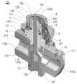
도 2a를 참조하면, 유체 유도 유닛(12)은 고정 플레이트(211)와 밀폐 둘레 벽(212)으로 이루어진 결합 플랜지; 고정 플레이트(211)의 중앙 부분에 대략적으로 원통 형상이 되도록 배치되고 유도 홈이 형성된 유도 블록(231); 유도 블록(231)으로부터 속이 빈 원통 형상으로 연장되는 관통 경로를 형성하는 유도 튜브(25); 및 유도 튜브(25)의 끝 부분을 형성하는 유도 팁(125)으로 이루어질 수 있다. 그리고 유도 팁(125)의 아래쪽에 유도 튜브(25)의 내부에 형성된 제2 연결 통로와 연결되는 와류 홀(124)이 형성될 수 있다.Referring to FIG. 2A, the
고정 플레이트(211)는 이 분야에서 공지된 임의의 형상을 가질 수 있고 밀폐 둘레 벽(212)은 일정한 높이 및 두께를 가지는 환형의 벽 구조를 가질 수 있다. 그리고 유도 블록(231)은 전체적으로 밀폐 둘레 벽(212)에 비하여 큰 높이를 가지도록 형성될 수 있다. 밀폐 둘레 벽(212)과 유도 블록(231) 사이에 원형으로 적어도 하나의 유도 경로(122)가 형성될 수 있다. 유도 홈은 유도 블록(231)의 외부 면으로부터 폭 및 깊이가 작아지도록 유도 블록(231)의 반지름 방향에 대하여 경사지도록 형성될 수 있고 원주 방향으로 따라 다수 개가 형성될 수 있다. 유도 홈은 와류 발생기(14)의 둘레 면에 형성된 유체 유도 경로와 연결될 수 있고 유도 경로(122)를 유입된 가압 기체는 빠른 속도로 소용돌이를 형성하면서 상기 유체 유도 경로를 따라 이동될 수 있다. 상기 유체 유도 경로를 따라 이동된 가압 기체는 와류 발생기(14)의 경사진 위쪽 면을 따라 분무 홀로 유도될 수 있다.The
와류 홀(124)은 유도 튜브(25)의 둘레 면을 따라 다수 개가 형성될 수 있고 유도 튜브(25)의 내부에 형성된 제2 연결 통로와 연결될 수 있다. 유도 팁(125)은 원뿔대의 형상을 가질 수 있다. 이와 같은 원뿔대의 형상은 경사면을 따라 유체가 유도되도록 하는 것에 의하여 전단력이 향상되도록 하면서 유체의 분무가 균일하게 이루어지도록 한다. 유도 튜브(25)와 유도 팁(125)을 관통하는 관통 홀(222)을 통하여 제2 공급 경로(133b)가 관통되도록 배치될 수 있다. 관통 홀(222)은 위에서 설명된 관통 경로에 해당된다.A plurality of vortex holes 124 may be formed along the circumferential surface of the
도 2b의 (가)를 참조하면, 연결 패드(16)는 전체적으로 판형이 되는 환형 스트립 형상이 될 수 있고, 스트립을 따라 다수 개의 유도 홀(161)이 형성될 수 있다. 유도 홀(161)은 위에서 설명된 제1 연결 통로와 연결될 수 있고 유체 유도 유닛(12)에 형성된 유도 경로(122)와 연결될 수 있다.Referring to FIG. 2 (b), the connecting
도 2b의 (나)를 참조하면, 와류 발생기(14)는 유도 튜브(25)가 관통하는 삽입 홀(141) 및 삽입 홀(141)의 중심으로 원형의 벽을 형성하는 와류 형성 몸체(142) 및 와류 형성 몸체(142)에 형성된 유체 유도 경로(143)로 이루어질 수 있다. 와류 형성 몸체(142)는 전체적으로 일정한 두께 및 높이를 가지는 원형 벽 구조를 형성할 수 있다. 유체 유도 경로(143)는 원형의 벽을 다수 개의 조각으로 분리시키는 분리 갭의 형상으로 만들어질 수 있다. 유체 유도 경로(143)는 와류 형성 몸체(142)의 외부로부터 안쪽으로 갈수록 깊이가 작아지면서 경사진 방향으로 연장되도록 형성될 수 있다. 이와 같은 구조로 인하여 기체는 빠르게 가속이 되면서 와류를 형성하면서 액체와 충돌하게 된다.2b, the
도 2의 (다)를 참조하면, 분무 캡(15)은 수용 공간(153)을 형성하는 유도 하우징(151), 유도 하우징(151) 및 유도 하우징의 끝 부분에 형성된 분무 홀(152)로 이루어질 수 있다. 분무 홀(152)이 형성되는 면은 경사면이 될 수 있고 서로 다른 경사 수준을 가진 다수 개의 경사면으로 이루어질 수 있다. 예를 들어 분무 홀(152)에 인접하는 둘레 면은 액체의 분무 범위에 따라 큰 경사를 가지도록 환형으로 만들어질 수 있고 그리고 중간 부분은 액체와 기체가 함께 혼합되어 빠르게 유도되도록 작은 경사를 가지도록 만들어질 수 있다. 상기 큰 경사는 유도 하우징(151)의 길이 방향을 기준으로 하는 각을 의미한다.2, the
다양한 형상을 가진 분무 캡(15)이 본 발명에 따른 노즐 어셈블리(10)에 적용될 수 있고 본 발명은 제시된 실시 예에 제한되지 않는다.A
아래에서 본 발명에 따른 노즐 어셈블리(10)의 작동 과정에 대하여 설명된다.The operation of the
도 3a 및 도 3b는 본 발명에 따른 노즐 어셈블리(10)의 작동 과정의 실시 예를 도시한 것이다.3A and 3B illustrate an embodiment of the operation of the
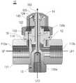
도 3a 및 도 3b를 참조하면, 기체와 같은 제1 유체(GF)가 제1 유입 통로(112a)를 통하여 유입되고, 제1 액체와 같은 제2 유체(LF1)이 제2 유입 통로(112b)를 통하여 유입될 수 있다. 그리고 미립자로 만들어져야 할 제2 액체와 같은 제3 유체(LF2)가 제1 공급 경로(133a)를 통하여 공급될 수 있다.3A and 3B, a first fluid GF, such as a gas, flows through the
제1 유체(GF)는 공급 몸체(111)에 형성된 제1 연결 통로(114) 및 연결 패드(16)를 경유하여 유체 유도 유닛(12)에 형성된 유도 경로(122)로 유도될 수 있다. 이후 제1 유체(GF)는 와류 발생기(14)에 형성된 유체 유도 경로(143)를 통하여 분무 홀(152)로 유도될 수 있다. 또한 제2 유체(LF1)은 유체 유도 유닛(12)에 형성된 제2 연결 통로(123)을 경유하여 와류 홀(124)로 유도되어 와류 발생기(14)로 이송될 수 있다. 이후 와류 발생기(14)에서 제1 유체(GF)와 함께 분무 홀(152)로 유도될 수 있다.The first fluid GF may be introduced into the
제3 유체(LF2)는 제1 공급 경로(133a) 및 제2 공급 경로(133b)를 경유하여 분무 홀(152)로 유도될 수 있다. 제3 유체(LF2)는 분무 홀(152)을 통하여 분무되면서 와류 형태로 되어 분무 팁의 위쪽 경사면을 따라 분무 홀(152)을 통하여 환형으로 분무되는 제1 유체(LF1) 및 제2 유체(LF2)에 의하여 강한 전단력을 받는다. 이로 인하여 제3 유체(LF2)는 균일한 미립자로 분무될 수 있다.The third fluid LF2 may be led to the
본 발명에 따른 노즐 어셈블리(10)는 다양한 유체가 미립자 형태로 균일하게 분무되도록 할 수 있고 본 발명은 제시된 실시 예에 제한되지 않는다.The
본 발명에 따른 액체 미립화 노즐 어셈블리(10)는 일차로 와류 발생기(14)에서 액체와 기체의 충돌에 의하여 미립자를 형성하고, 다시 환형 통로로 분사되면서 이차적으로 미립자를 형성시킨다. 이로 인하여 많은 공급량의 액체에 대한 균일한 미립자 형성이 가능하도록 하면서 이와 동시에 낮은 압력으로 미립자가 형성될 수 있도록 한다. 또한 본 발명에 따른 액체 미립화 노즐 어셈블리는 고온 연소로의 가스 냉각용 및 공기 조화기용 노즐로 적용되어 질소산화물(NOX), SO2, 수은, 비소 또는 크롬과 같은 중금속의 제거가 가능하도록 한다. 추가로 본 발명에 따른 노즐 어셈블리는 작업장 또는 공장 설비 내에 설치되어 유해 가스의 제거에 적용될 수 있도록 하면서 오존 발생을 위한 액체 또는 탈취 제거를 위한 제제가 혼합된 액체의 분무를 위한 시스템에 적용될 수 있도록 한다. 추가로 본 발명에 따른 노즐 어셈블리는 예를 들어 살균을 위한 유체 또는 오존수와 같은 것이 다른 유체와 함께 동시에 분무되는 것이 가능하도록 하는 것에 의하여 공기 정화 또는 오염 물질의 제거 효과가 상승되도록 한다.The liquid
위에서 본 발명은 제시된 실시 예를 참조하여 상세하게 설명이 되었지만 이 분야에서 통상의 지식을 가진 자는 제시된 실시 예를 참조하여 본 발명의 기술적 사상을 벗어나지 않는 범위에서 다양한 변형 및 수정 발명을 만들 수 있을 것이다. 본 발명은 이와 같은 변형 및 수정 발명에 의하여 제한되지 않으며 다만 아래에 첨부된 청구범위에 의하여 제한된다.While the present invention has been particularly shown and described with reference to exemplary embodiments thereof, it will be understood by those of ordinary skill in the art that various changes in form and details may be made therein without departing from the spirit and scope of the invention . The invention is not limited by these variations and modifications, but is limited only by the claims appended hereto.
10: 노즐 어셈블리 11: 유체 공급 몸체
111: 공급 몸체 112a, 112b: 제1, 2 유입 통로
113: 체결 공 114: 제1 연결 통로
12: 유체 유도 유닛 121: 유도 몸체
122: 유도 경로 123: 제2 연결 통로
124: 와류 홀 125: 유도 팁
127: 유도 부분
13: 유체 이송 유닛 131: 이송 몸체
132: 공급 커넥터 133a, 133b: 제1, 2 공급 경로
14: 와류 발생기 141: 삽입 홀
142: 와류 형성 몸체 143: 유체 유도 경로
15: 분무 캡 151: 유도 하우징
152: 분무 홀 153: 수용 공간
16: 연결 패드 161: 유도 홀
221: 고정 플레이트 212: 밀폐 둘레 벽
222: 관통 홀 231: 유도 블록
25: 유도 튜브10: nozzle assembly 11: fluid supply body
111:
113: fastening hole 114: first connection passage
12: fluid induction unit 121: induction body
122: guide path 123: second connection passage
124: vortex hole 125: induction tip
127:
13: Fluid feed unit 131: Feed body
132:
14: vortex generator 141: insertion hole
142: vortex forming body 143: fluid induction path
15: Spray cap 151: Induction housing
152: spray hole 153: accommodation space
16: connection pad 161: guide hole
221: Fixing plate 212: Closed perimeter wall
222: through hole 231: guide block
25: induction tube
Claims (6)
Translated fromKorean유체 공급 몸체(11)에 결합되고, 유체 이송이 가능한 공급 경로가 형성된 유체 유도 유닛(12);
유체 유도 유닛(12)에 결합되고 상기 적어도 2개의 유입 통로(112a, 112b)로부터 유입된 유체를 유도하기 위한 통로가 형성된 유체 이송 유닛(13);
유체 이송 유닛(13)으로부터 유도되는 유체로부터 와류를 형성하는 와류 발생기(14); 및
유체 유도 유닛(12)으로부터 이송된 유체 및 와류 발생기(14)에서 발생된 와류를 분무시키는 분무 캡(15)을 포함하고,
상기 적어도 2개의 유입 통로 중 하나의 유입 통로(112a)를 유체 이송 유닛(13)과 연결하는 제1 연결 통로(114)와 다른 하나의 유입 통로(112b)와 연결되도록 유체 이송 유닛(13)의 둘레에 형성된 제2 연결 통로(123)을 더 포함하며,
상기 제2 연결 통로(123)에 와류 발생기(14)로 연결되도록 와류 홀(124)이 형성되고,
상기 분무 캡(15)의 중앙에 형성된 분무 홀(152)을 더 포함하고, 상기 분무 홀(152)은 둘레 면을 따라 환형으로 상기 2개의 유입 통로(112a, 112b)로부터 공급된 유체가 함께 분무되도록 형성되는 다수 유체 미립자 분무용 노즐 어셈블리.A fluid supply body (11) formed with at least two inlet passages (112a, 112b);
A fluid induction unit (12) coupled to the fluid supply body (11), the fluid induction unit (12) having a supply path through which fluid can be transferred;
A fluid transfer unit (13) coupled to the fluid induction unit (12) and provided with a passage for guiding the fluid introduced from the at least two inflow passages (112a, 112b);
A vortex generator 14 that forms a vortex from the fluid derived from the fluid transfer unit 13; And
And a spray cap (15) for spraying the fluid transferred from the fluid guiding unit (12) and the vortex generated in the vortex generator (14)
The fluid transfer unit 13 is connected to the first connection passage 114 connecting one of the at least two inflow passages with the fluid transfer unit 13 and the other inflow passage 112b. And a second connection passage (123) formed around the first connection passage,
A vortex hole 124 is formed in the second connection passage 123 so as to be connected to the vortex generator 14,
The apparatus of claim 1, further comprising a spray hole (152) formed in the center of the spray cap (15), wherein the spray hole (152) is annular along the circumferential surface and the fluid supplied from the two inflow passages (112a, 112b) Wherein the plurality of fluid microparticles are formed in the nozzle assembly.
The nozzle assembly of claim 1, wherein the fluid in the vortex generator (14) is directed along an inclined plane.
Priority Applications (1)
| Application Number | Priority Date | Filing Date | Title |
|---|---|---|---|
| KR1020140190767AKR101732648B1 (en) | 2014-12-26 | 2014-12-26 | A Nozzle Assembly for Atomizing Liquid |
Applications Claiming Priority (1)
| Application Number | Priority Date | Filing Date | Title |
|---|---|---|---|
| KR1020140190767AKR101732648B1 (en) | 2014-12-26 | 2014-12-26 | A Nozzle Assembly for Atomizing Liquid |
Publications (2)
| Publication Number | Publication Date |
|---|---|
| KR20160079428A KR20160079428A (en) | 2016-07-06 |
| KR101732648B1true KR101732648B1 (en) | 2017-05-04 |
Family
ID=56502389
Family Applications (1)
| Application Number | Title | Priority Date | Filing Date |
|---|---|---|---|
| KR1020140190767AActiveKR101732648B1 (en) | 2014-12-26 | 2014-12-26 | A Nozzle Assembly for Atomizing Liquid |
Country Status (1)
| Country | Link |
|---|---|
| KR (1) | KR101732648B1 (en) |
Cited By (2)
| Publication number | Priority date | Publication date | Assignee | Title |
|---|---|---|---|---|
| KR20200022941A (en)* | 2018-08-24 | 2020-03-04 | 주식회사 휴온스메디케어 | mathod and apparatus for vaporizing sterilant to disinfecting air |
| KR20220087317A (en) | 2020-12-17 | 2022-06-24 | 뉴프 주식회사 | Atomizing nozzle for fogponics |
Families Citing this family (2)
| Publication number | Priority date | Publication date | Assignee | Title |
|---|---|---|---|---|
| CN106621637A (en)* | 2017-02-13 | 2017-05-10 | 昆明奥图环保设备股份有限公司 | Dry fog box |
| CN113230788B (en)* | 2021-04-15 | 2023-04-25 | 西安石油大学 | A fine dust spray dust suppression system and its intelligent atomization dust suppression method |
Citations (3)
| Publication number | Priority date | Publication date | Assignee | Title |
|---|---|---|---|---|
| JP2005288390A (en) | 2004-04-02 | 2005-10-20 | Kyoritsu Gokin Co Ltd | Two-fluid nozzle and spraying method |
| KR100855309B1 (en)* | 2007-03-27 | 2008-09-04 | 한상철 | Pipe cleaning system and nozzles used in the system |
| JP2010247133A (en)* | 2009-04-14 | 2010-11-04 | Sunny Kogyo:Kk | Two-fluid nozzle |
Family Cites Families (2)
| Publication number | Priority date | Publication date | Assignee | Title |
|---|---|---|---|---|
| KR100622987B1 (en) | 2004-06-10 | 2006-09-19 | 한국에너지기술연구원 | 2 Fluid Injection Nozzles |
| KR101363021B1 (en) | 2013-03-06 | 2014-02-14 | 이노비스 주식회사 | Spray nozzle |
- 2014
- 2014-12-26KRKR1020140190767Apatent/KR101732648B1/enactiveActive
Patent Citations (3)
| Publication number | Priority date | Publication date | Assignee | Title |
|---|---|---|---|---|
| JP2005288390A (en) | 2004-04-02 | 2005-10-20 | Kyoritsu Gokin Co Ltd | Two-fluid nozzle and spraying method |
| KR100855309B1 (en)* | 2007-03-27 | 2008-09-04 | 한상철 | Pipe cleaning system and nozzles used in the system |
| JP2010247133A (en)* | 2009-04-14 | 2010-11-04 | Sunny Kogyo:Kk | Two-fluid nozzle |
Cited By (3)
| Publication number | Priority date | Publication date | Assignee | Title |
|---|---|---|---|---|
| KR20200022941A (en)* | 2018-08-24 | 2020-03-04 | 주식회사 휴온스메디케어 | mathod and apparatus for vaporizing sterilant to disinfecting air |
| KR102142952B1 (en) | 2018-08-24 | 2020-08-10 | 주식회사 휴온스메디케어 | mathod and apparatus for vaporizing sterilant to disinfecting air |
| KR20220087317A (en) | 2020-12-17 | 2022-06-24 | 뉴프 주식회사 | Atomizing nozzle for fogponics |
Also Published As
| Publication number | Publication date |
|---|---|
| KR20160079428A (en) | 2016-07-06 |
Similar Documents
| Publication | Publication Date | Title |
|---|---|---|
| EP2739400B1 (en) | Pressurized air assisted spray nozzle assembly | |
| KR101732643B1 (en) | A Nozzle Assembly for Atomizing Liquid | |
| JP6487041B2 (en) | Atomizer nozzle | |
| KR101119211B1 (en) | Apparatus Generating Minute Particles And Micro/Nano Bubbles And System Using The Same | |
| KR101732648B1 (en) | A Nozzle Assembly for Atomizing Liquid | |
| US10201794B2 (en) | High efficiency/low pressure catalytic cracking spray nozzle assembly | |
| WO2008024032A1 (en) | Liquid sprayer | |
| KR101965427B1 (en) | Two-fluid fog forming device | |
| JP2009226402A (en) | Device for producing and spraying aerosol | |
| SI22923B (en) | Processing device for coating particles | |
| CN102947007A (en) | External mix air assisted spray nozzle assembly | |
| RU2324582C2 (en) | Method of cutting zone cooling and device for its implementation | |
| KR20160000771A (en) | A Evaporation Cooling Type of Spraying Apparatus Having Nozzle Assembly Forming Hyperfine Atomized Droplet | |
| KR101695433B1 (en) | A Nozzle Assembly with an Air Curtain Forming Unit | |
| CN110997155B (en) | Atomizer nozzle | |
| RU119264U1 (en) | PNEUMATIC SPRAY | |
| TWI581864B (en) | Powder distributing apparatus | |
| RU2180711C1 (en) | Multi-stage jet apparatus | |
| CN206951014U (en) | A kind of high efficient gas and liquid blender | |
| RU2311964C1 (en) | Liquid sprayer | |
| EP3015173B1 (en) | Internal mix air atomizing spray nozzle | |
| KR20160093961A (en) | A Nozzle Assembly Having Low Scattering Property | |
| EP3813967A1 (en) | Gas disperser for guiding gas into a chamber, spray drying apparatus comprising such a gas disperser, and method of aligning a stream of gas in a gas disperser | |
| KR20170041441A (en) | Injection Nozzle Having Control Unit of Flow | |
| KR20170043485A (en) | A Nozzle Assembly Forming a Structure of an Air Curtain |
Legal Events
| Date | Code | Title | Description |
|---|---|---|---|
| A201 | Request for examination | ||
| PA0109 | Patent application | Patent event code:PA01091R01D Comment text:Patent Application Patent event date:20141226 | |
| PA0201 | Request for examination | ||
| E902 | Notification of reason for refusal | ||
| PE0902 | Notice of grounds for rejection | Comment text:Notification of reason for refusal Patent event date:20160525 Patent event code:PE09021S01D | |
| PG1501 | Laying open of application | ||
| E701 | Decision to grant or registration of patent right | ||
| PE0701 | Decision of registration | Patent event code:PE07011S01D Comment text:Decision to Grant Registration Patent event date:20170126 | |
| GRNT | Written decision to grant | ||
| PR0701 | Registration of establishment | Comment text:Registration of Establishment Patent event date:20170426 Patent event code:PR07011E01D | |
| PR1002 | Payment of registration fee | Payment date:20170426 End annual number:3 Start annual number:1 | |
| PG1601 | Publication of registration | ||
| PR1001 | Payment of annual fee | Payment date:20200427 Start annual number:4 End annual number:4 | |
| PR1001 | Payment of annual fee | Payment date:20210426 Start annual number:5 End annual number:5 | |
| PR1001 | Payment of annual fee | Payment date:20220425 Start annual number:6 End annual number:6 | |
| PR1001 | Payment of annual fee | Payment date:20230425 Start annual number:7 End annual number:7 | |
| PR1001 | Payment of annual fee | Payment date:20240425 Start annual number:8 End annual number:8 |