KR101732466B1 - A method of manufacturing the digital model for implant - Google Patents
A method of manufacturing the digital model for implantDownload PDFInfo
- Publication number
- KR101732466B1 KR101732466B1KR1020160032212AKR20160032212AKR101732466B1KR 101732466 B1KR101732466 B1KR 101732466B1KR 1020160032212 AKR1020160032212 AKR 1020160032212AKR 20160032212 AKR20160032212 AKR 20160032212AKR 101732466 B1KR101732466 B1KR 101732466B1
- Authority
- KR
- South Korea
- Prior art keywords
- hole
- fixture
- analog
- cylindrical portion
- implant
- Prior art date
- Legal status (The legal status is an assumption and is not a legal conclusion. Google has not performed a legal analysis and makes no representation as to the accuracy of the status listed.)
- Active
Links
- 239000007943implantSubstances0.000titleclaimsabstractdescription51
- 238000004519manufacturing processMethods0.000titleclaimsabstractdescription12
- 238000000034methodMethods0.000claimsabstractdescription28
- 210000000214mouthAnatomy0.000claimsabstractdescription22
- 238000003754machiningMethods0.000claimsdescription29
- 210000000988bone and boneAnatomy0.000claimsdescription22
- 238000003801millingMethods0.000claimsdescription12
- 238000013461designMethods0.000claimsdescription11
- 238000003780insertionMethods0.000claimsdescription7
- 230000037431insertionEffects0.000claimsdescription7
- 230000003239periodontal effectEffects0.000claimsdescription5
- 229910000831SteelInorganic materials0.000claimsdescription4
- 239000010959steelSubstances0.000claimsdescription4
- 238000012545processingMethods0.000claimsdescription3
- 230000010485copingEffects0.000description8
- 238000005553drillingMethods0.000description8
- 229910052602gypsumInorganic materials0.000description7
- 239000010440gypsumSubstances0.000description7
- 238000012360testing methodMethods0.000description3
- 230000008878couplingEffects0.000description2
- 238000010168coupling processMethods0.000description2
- 238000005859coupling reactionMethods0.000description2
- 238000005520cutting processMethods0.000description2
- 238000002513implantationMethods0.000description2
- 238000009434installationMethods0.000description2
- 239000000463materialSubstances0.000description2
- 239000011505plasterSubstances0.000description2
- 229910001069Ti alloyInorganic materials0.000description1
- RTAQQCXQSZGOHL-UHFFFAOYSA-NTitaniumChemical compound[Ti]RTAQQCXQSZGOHL-UHFFFAOYSA-N0.000description1
- 210000003484anatomyAnatomy0.000description1
- 230000000694effectsEffects0.000description1
- 230000004927fusionEffects0.000description1
- 238000007689inspectionMethods0.000description1
- 238000005259measurementMethods0.000description1
- 230000003278mimic effectEffects0.000description1
- 210000005036nerveAnatomy0.000description1
- 238000002360preparation methodMethods0.000description1
- 229910052719titaniumInorganic materials0.000description1
- 239000010936titaniumSubstances0.000description1
Images


Classifications
- A—HUMAN NECESSITIES
- A61—MEDICAL OR VETERINARY SCIENCE; HYGIENE
- A61C—DENTISTRY; APPARATUS OR METHODS FOR ORAL OR DENTAL HYGIENE
- A61C13/00—Dental prostheses; Making same
- A61C13/0003—Making bridge-work, inlays, implants or the like
- A61C13/0004—Computer-assisted sizing or machining of dental prostheses
- A—HUMAN NECESSITIES
- A61—MEDICAL OR VETERINARY SCIENCE; HYGIENE
- A61C—DENTISTRY; APPARATUS OR METHODS FOR ORAL OR DENTAL HYGIENE
- A61C13/00—Dental prostheses; Making same
- A61C13/0003—Making bridge-work, inlays, implants or the like
- A61C13/0006—Production methods
- A61C13/0019—Production methods using three dimensional printing
- A—HUMAN NECESSITIES
- A61—MEDICAL OR VETERINARY SCIENCE; HYGIENE
- A61C—DENTISTRY; APPARATUS OR METHODS FOR ORAL OR DENTAL HYGIENE
- A61C13/00—Dental prostheses; Making same
- A61C13/34—Making or working of models, e.g. preliminary castings, trial dentures; Dowel pins [4]
- A—HUMAN NECESSITIES
- A61—MEDICAL OR VETERINARY SCIENCE; HYGIENE
- A61C—DENTISTRY; APPARATUS OR METHODS FOR ORAL OR DENTAL HYGIENE
- A61C8/00—Means to be fixed to the jaw-bone for consolidating natural teeth or for fixing dental prostheses thereon; Dental implants; Implanting tools
- A61C8/0001—Impression means for implants, e.g. impression coping
- A—HUMAN NECESSITIES
- A61—MEDICAL OR VETERINARY SCIENCE; HYGIENE
- A61C—DENTISTRY; APPARATUS OR METHODS FOR ORAL OR DENTAL HYGIENE
- A61C8/00—Means to be fixed to the jaw-bone for consolidating natural teeth or for fixing dental prostheses thereon; Dental implants; Implanting tools
- A61C8/0048—Connecting the upper structure to the implant, e.g. bridging bars
- A61C8/005—Connecting devices for joining an upper structure with an implant member, e.g. spacers
- A—HUMAN NECESSITIES
- A61—MEDICAL OR VETERINARY SCIENCE; HYGIENE
- A61C—DENTISTRY; APPARATUS OR METHODS FOR ORAL OR DENTAL HYGIENE
- A61C8/00—Means to be fixed to the jaw-bone for consolidating natural teeth or for fixing dental prostheses thereon; Dental implants; Implanting tools
- A61C8/0089—Implanting tools or instruments
- A—HUMAN NECESSITIES
- A61—MEDICAL OR VETERINARY SCIENCE; HYGIENE
- A61C—DENTISTRY; APPARATUS OR METHODS FOR ORAL OR DENTAL HYGIENE
- A61C9/00—Impression cups, i.e. impression trays; Impression methods
- A61C9/004—Means or methods for taking digitized impressions
- A61C9/0046—Data acquisition means or methods
Landscapes
- Health & Medical Sciences (AREA)
- Animal Behavior & Ethology (AREA)
- Dentistry (AREA)
- Epidemiology (AREA)
- Life Sciences & Earth Sciences (AREA)
- Oral & Maxillofacial Surgery (AREA)
- General Health & Medical Sciences (AREA)
- Public Health (AREA)
- Veterinary Medicine (AREA)
- Orthopedic Medicine & Surgery (AREA)
- Engineering & Computer Science (AREA)
- Manufacturing & Machinery (AREA)
- Dental Prosthetics (AREA)
Abstract
Translated fromKoreanDescription
Translated fromKorean본 발명은 임플란트용 디지털 모델 및 그 제조 방법에 관한 것으로서, 더 상세하게는 치아 디지털 모델에 부품인 랩 아날로그를 설치하여 임플란트 시술에 따른 픽스츄어의 위치와 방향을 구강 외부에서 동일하게 시뮬레이션할 수 있도록 하는 임플란트용 디지털 모델 및 그 제조 방법에 관한 것이다.[0001] The present invention relates to a digital model for an implant and a method of manufacturing the same, and more particularly, to providing a lab analog that is a component of a tooth digital model so that the position and direction of a fixture according to an implant procedure can be simulated equally outside the mouth The present invention relates to a digital model for an implant and a method of manufacturing the same.
일반적으로, 임플란트(implant)란 심하게 손상된 치아를 대신하기 위해 사용되는 보철물로서, 치아가 빠진 부분에 티타늄이나 티타늄합금으로 만들어진 인공치근을 턱뼈에 이식하여 인공 치아를 형성함으로써 본래 자신의 치아와 유사한 형태로 일상 생활을 영위할 수 있는 치과적인 시술방법을 통칭하는 것이다.In general, an implant is a prosthesis used to replace a severely damaged tooth. By implanting an artificial tooth made of titanium or a titanium alloy into the jawbone to form an artificial tooth at a portion where teeth are missing, Is a dental procedure that can lead to daily life.
따라서 임플란트는 틀니, 브릿지 등을 이용한 시술 방법과 비교할 때, 시술이 필요한 치아를 제외한 주변의 치아에 손상을 주지 않고, 자연 치아와 매우 유사한 장점이 있어서 최근 크게 각광받고 있는 시술방법이다.Therefore, compared with the dentures and bridges, the implant has a remarkable similarity to the natural teeth without damaging the surrounding teeth except the teeth requiring the operation.
이러한 임플란트는 먼저 시술할 환자의 잇몸을 절개하여 치조골을 노출한 후에 임플란트를 식립할 위치를 결정하고, 상기 위치에 드릴과 같은 천공 도구를 사용하여 치조골의 소정 위치를 천공하여 픽스츄어(fixture)가 식립될 천공을 형성한다. 그리고 식립된 픽스츄어가 치조골과 융착되면, 상기 픽스츄어에 지대주{abutment) 및 인공치관(crown)을 결합시킨 후에 잇몸을 덮음으로써 임플란트의 설치가 완료된다.The implant is first prepared by cutting the gum of a patient to be treated, exposing the alveolar bone, determining a position at which the implant is to be placed, puncturing a predetermined position of the alveolar bone using a perforating tool such as a drill, To form the perforations to be placed. When the inserted fixture is fused with the alveolar bone, the abutment and the crown are combined with the fixture, and then the gums are covered to complete the installation of the implant.
그러므로 임플란트의 시술에 있어서 성공적인 식립을 좌우하는 작업은 치조골에 픽스츄어가 매식될 홈을 드릴링하는 작업이라고 할 수 있다. 이는 치아의 전체적인 상태나 임플란트 시술이 필요한 치아의 위치, 치조골의 상태 등 다양한 요인을 고려하여 임플란트의 식립 위치 및 깊이와 방향을 결정해야 성공적인 임플란트 시술을 기대할 수 있는데, 임플란트 시술의 첫 단계라 할 수 있는 치조골 천공이 불안정하게 이루어질 경우에 임플란트의 식립 위치와 방향 및 깊이가 충족될 수 없기 때문이다.Therefore, the task of determining successful implantation in the implant procedure is to drill the groove into the alveolar bone to which the fixture is to be inserted. This implies that the implant placement, depth and direction should be determined in consideration of various factors such as the overall condition of the teeth, the position of the teeth requiring the implant treatment, the condition of the alveolar bone, etc., and successful implantation can be expected. This is because when the perforation of the alveolar bone is unstable, the position, direction and depth of the implant can not be met.
이와 같은 치조골 천공을 위한 드릴링 작업은 초심자뿐만 아니라 숙련자에게도 작업 과정에서 깊이 및 방향을 정확하게 가늠하기가 상당히 어렵다는 난점이 있다. 특히 시술 경험이 풍부하지 않은 초보자의 경우, 시술 도중 별도의 특별한 측정 단계 없이 드릴링 된 깊이를 가늠한다는 것은 매우 어려울 수 있다.This drilling operation for alveolar bone drilling has a difficulty in not only a beginner but also an expert, it is very difficult to precisely measure the depth and direction in the course of work. Especially for beginners who are not experienced with the procedure, it can be very difficult to measure the drilled depth without any special measurement steps during the procedure.
또한, 픽스츄어를 식립하기 위한 홈을 치조골에 드릴링 할 때, 시술자가 드릴에 힘을 가하여 드릴링 작업을 수행하면서 현재 어느 정도까지 깊이로 드릴링 작업이 이루어졌는지 판단하기가 용이하지 않은 관계로 소정의 깊이를 넘어서 드릴링 하게 되면 드릴이 치조골에 분포되어 있는 신경을 손상시킬 우려가 있다. 그 반대로 소정의 드릴링 깊이에 도달하기 전에 드릴링 작업을 종료한 경우에는 드릴링된 홈의 깊이가 얕아서 픽스츄어 고정에 과도한 힘이 소요될 뿐만 아니라, 이로 인해 홈 주위의 나사산이 손상되거나 홈에 고정될 픽스츄어(fixture)가 완벽하게 고정되지 못하게 되어 추후 재 시술을 하게 되는 문제점 등이 발생한다.Further, when drilling a groove for placing a fixture, it is not easy to determine to what extent the drilling operation has been performed to a certain degree while the operator performs a drilling operation by applying a force to the drill. The drill may damage the nerves distributed in the alveolar bone. On the contrary, when the drilling operation is completed before reaching the predetermined drilling depth, the depth of the drilled groove is shallow, so that an excessive force is required to fix the fixture, thereby causing a screw around the groove to be damaged or fixed to the groove. (fixture) can not be fixed perfectly, which causes re-operation.
본 발명은 상기 종래 기술에 관련된 문제점을 개선하기 위하여 안출된 것으로서, 본 발명의 목적은 치아 디지털 모델에 부품인 랩 아날로그를 설치하여 임플란트 시술에 따른 픽스츄어의 위치와 방향을 구강 외부에서 동일하게 시뮬레이션할 수 있도록 하는 임플란트용 디지털 모델을 제공하기 위함이다.It is an object of the present invention to provide a lab analog which is a component of a tooth digital model and to simulate the position and direction of a fixture according to an implant procedure equally outside the oral cavity. The present invention provides a digital model for an implant.
본 발명의 다른 목적은 랩 아날로그를 제공함에 있어 구강 내의 픽스츄어의 방향과 위치를 잘 모사 할 수 있도록 하는 랩 아날로그 부품을 제공하는 데 있다.It is another object of the present invention to provide a lab analog component that is capable of simulating the orientation and position of a fixture in the mouth in providing a lab analog.
본 발명의 또 다른 목적은 랩 아날로그가 삽입되는 디지털 모델의 홀 가공시에 간단한 밀링 가공으로 홀 가공이 간단하고 신속하게 이루어지도록 하는 임플란트용 디지털 모델을 제공하는 데 있다.It is still another object of the present invention to provide a digital model for an implant that allows simple and fast hole machining by simple milling during hole machining of a digital model into which a lab analog is inserted.
본 발명의 또 다른 목적은 모델 가공시 사용한 공구만으로 디지털 모델의 홀 가공할 수 있는 임플란트용 디지털 모델을 제공하는 데 있다.Another object of the present invention is to provide a digital model for an implant that can be used for hole machining of a digital model using only a tool used for model machining.
본 발명의 또 다른 목적은 디지털 모델에서 랩 아날로그가 삽입될 홀 부분을 볼앤드밀(ball end mill), 플랫앤드밀(flat end mill)이 조합된 도구로 가공 가능한 형태의 랩 아날로그 형상 부품을 대량 생산하도록 제공하는 데 있다.It is another object of the present invention to provide a method for mass production of a lab analog shape part in a form that can be machined by a tool combined with a ball end mill, a flat end mill, .
본 발명의 또 다른 목적은 치아 디지털 모델에 부품인 랩 아날로그를 설치하여 임플란트 시술에 따른 픽스츄어의 위치와 방향을 구강 외부에서 동일하게 시뮬레이션할 수 있도록 하는 임플란트용 디지털 모델 제작 방법을 제공하는 데 있다.It is another object of the present invention to provide a method of manufacturing a digital model for an implant, in which a lap analog, which is a component of a tooth digital model, is installed so that the position and direction of a fixture according to an implant procedure can be simulated equally outside the oral cavity .
본 발명은 상술한 목적을 달성하기 위하여, CAD/CAM에 의해 임플란트 시술을 위한 픽스츄어가 삽입될 홀 구멍이 가공된 모델 본체와; 상기 모델 본체의 홀 구멍에 맞춤 끼움 결합되는 랩 아날로그를 포함하는 임플란트용 디지털모델로서, 상기 홀 구멍에 삽입되는 랩 아날로그에 의해 임플란트 시술에 따른 픽스츄어의 위치와 방향을 구강 외부에서 동일하게 시뮬레이션할 수 있도록 이루어짐을 특징으로 하는 임플란트용 디지털 모델을 개시한다.In order to achieve the above object, according to the present invention, there is provided a prosthetic handpiece comprising: a model body formed with a hole for inserting a fixture for implant treatment by CAD / CAM; Wherein the position and direction of the fixture according to the implant procedure are simulated in the oral cavity in the same manner by a lab analog inserted into the hole, The implantable implantable implantable implantable implantable implantable implantable medical device.
또한, 상기 홀 구멍은 상기 랩 아날로그의 형상에 맞대응하는 형태의 천공 홀 구조임을 특징으로 할 수 있다.In addition, the hole may have a perforation hole structure corresponding to the shape of the lab analog.
또한, 상기 홀 구멍은 CAD/CAM에 의해 가공되는 상단 가공부와; 상기 상단 가공부 보다 그 내경이 좁게 가공되는 하단 가공부를 포함하여 구성되는 것을 특징으로 할 수 있다.Further, the hole may have a top processing part that is processed by CAD / CAM; And a lower machining portion whose inner diameter is narrower than the upper machining portion.
또한, 상기 랩 아날로그는 밀링 방식에 의해 가공되는 부품 형태로서, 상측으로 큰 외경을 갖도록 형성되는 상부 원통부와; 상기 상부 원통부에서 하측으로 연장 형성되어 작은 외경을 갖도록 형성되는 하부 원통부를 포함하여 구성됨을 특징으로 할 수 있다.In addition, the lab analog is a part type processed by a milling method, and has an upper cylindrical portion formed to have a larger outer diameter toward the upper side; And a lower cylindrical portion extending downward from the upper cylindrical portion and having a smaller outer diameter.
또한, 상기 상부 원통부와 연결되는 하부 원통부는 상기 상부 원통부의 중심보다 그 중심이 어느 한쪽으로 편심되도록 형성됨을 특징으로 할 수 있다.The lower cylindrical portion connected to the upper cylindrical portion may be eccentrically centered with respect to the center of the upper cylindrical portion.
또한, 상기 상부 원통부의 수직 길이가 상기 하부 원통부 보다 짧게 형성되고, 상기 하부 원통부의 수직 길이가 상부 원통부 보다 더 길게 형성되는 것을 특징으로 할 수 있다.The vertical length of the upper cylindrical portion may be shorter than the lower cylindrical portion, and the vertical length of the lower cylindrical portion may be longer than that of the upper cylindrical portion.
본 발명은 상술한 목적을 달성하기 위하여, 피시술자의 구강 내의 시술하고자 하는 치주골에 픽스츄어를 식립하고, 상기 픽스츄어의 상부에 제공된 수용홈에 스캔 어벗트먼트를 삽입 고정하는 단계; 구강 스캐너로 3차원 스캔하여 3차원 모델링 파일을 얻어 식립된 픽스츄어에 대한 정확한 위치 및 방향 정보를 추출하는 단계; CAD의 모델 빌더를 사용하여 픽스츄어의 위치에 랩 아날로그가 삽입될 수 있도록 홀 구멍을 형성한 스틸 파일을 만들어 주고 홀 구멍에 대한 정보를 CAM에 제공하여 모델 본체를 디자인 가공하는 단계; 밀링 방식에 의해 가공되는 부품 형태로서 상기 홀 구멍에 삽입되는 랩 아날로그를 가공하는 단계; 정확한 임플란트 고정구멍 정보를 바탕으로 성형한 모델 본체의 홀 구멍에 지대주와 결합될 랩 아날로그를 장착하는 단계; 상기 홀 구멍에 정확하게 삽입된 랩 아날로그의 상부 홈에 성형한 지대주(abutment) 및 인공치아(crown)를 장착 후 형합 검사를 완료하는 단계를 포함하고, 상기 홀 구멍에 삽입된 랩 아날로그에 의해 임플란트 시술에 따른 픽스츄어의 위치와 방향을 구강 외부에서 동일하게 시뮬레이션할 수 있도록 이루어짐을 특징으로 하는 임플란트용 디지털 모델 제작 방법을 제공할 수 있다.In order to achieve the above-mentioned object, the present invention provides a method of inserting a fixture into a periodontal bone to be treated in an oral cavity of a physician, inserting and fixing a scan fitting in a receiving groove provided in an upper portion of the fixture; Dimensional scanning with an oral scanner to obtain a three-dimensional modeling file and extracting accurate position and orientation information for the placed fixture; A step of designing a model body by providing a CAM with a steel file in which a hole analog is inserted so that a lab analog can be inserted at a position of a fixture using a CAD model builder, Machining a lab analog to be inserted into the hole as a part type processed by a milling method; Mounting a lab analog to be combined with an abutment on a hole of a model body formed based on accurate implant fixture hole information; And a step of completing a fusion test after mounting an abutment and an artificial tooth formed in an upper groove of a lab analog accurately inserted into the hole, And the position and direction of the fixture according to the position of the fixture can be simulated equally in the oral cavity.
또한, 스캔 된 상기 홀 구멍을 통하여 3D printer용 디지털 모델 디자인에 따른 랩 아날로그의 스펙(상품명과 형상)을 지정하면 위에서 추론된 픽스츄어의 위치와 방향 정보를 이용하여 랩 아날로그가 픽스츄어를 잘 모사 할 수 있도록 3D printer용 디지털 모델을 디자인할 수 있도록 이루어짐을 특징으로 할 수 있다.Also, if the specification (product name and shape) of the lab analog according to the digital model design for the 3D printer is specified through the hole that has been scanned, the lab analog can well simulate the fixture using the position and direction information of the inferred fixture So that a digital model for a 3D printer can be designed.
본 발명은 치아 디지털 모델에 부품인 랩 아날로그를 설치하여 임플란트 시술에 따른 픽스츄어의 위치와 방향을 구강 외부에서 동일하게 시뮬레이션할 수 있도록 한다.In the present invention, a lap analog, which is a component of a tooth digital model, is installed so that the position and direction of a fixture according to an implant procedure can be simulated equally outside the oral cavity.
또한, 본 발명은 랩 아날로그를 제공함에 있어 구강 내에 식립된 픽스츄어의 방향과 위치를 잘 모사 할 수 있도록 하는 랩 아날로그 부품을 제공할 수 있다.In addition, the present invention can provide a lab analog component that can better mimic the orientation and position of the fixture implanted in the oral cavity in providing lab analog.
또한, 본 발명은 랩 아날로그가 삽입되는 디지털 모델의 홀 가공시에 간단한 밀링 가공으로 홀 가공이 간단하고 신속하게 이루어질 수 있도록 한다.Further, the present invention enables simple and rapid hole machining by a simple milling process in the hole machining of the digital model in which the lab analog is inserted.
또한, 본 발명은 모델 가공시 사용한 공구만으로 디지털 모델의 홀 가공이 가능하게 한다.Further, the present invention enables the hole machining of the digital model with only the tool used in model machining.
또한, 본 발명은 디지털 모델에서 랩 아날로그가 삽입될 홀 부분을 볼앤드밀, 플랫앤드밀이 조합된 도구로 가공 가능한 형태의 랩 아날로그 형상 부품을 대량 생산할 수 있는 효과가 있다.In addition, the present invention has the effect of mass-producing lab analog part in a form that can process a hole part into which a lab analog is inserted in a digital model with a tool combined with a ball end mill and a flat end mill.
또한, 본 발명은 치아 디지털 모델에 부품인 랩 아날로그를 설치하여 임플란트 시술에 따른 식립된 픽스츄어의 위치와 방향을 구강 외부에서 동일하게 시뮬레이션할 수 있도록 하는 임플란트용 디지털 모델 제작 방법을 제공할 수 있다.In addition, the present invention can provide a method of manufacturing a digital model for an implant, in which a lap analog, which is a component of a tooth digital model, is installed so that the position and orientation of a fixture implanted according to an implant procedure can be simulated equally outside the oral cavity .
도 1 내지 도 8은 본 발명에 의한 디지털 모델을 보인 실시 예로서,
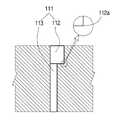
도 1은 임플란트 시술을 보인 예시도,
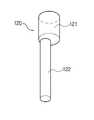
도 2는 본 발명에 따른 모델 본체에 랩 아날로그가 삽입되는 것을 보인 예시도,
도 3은 본 발명에 따른 모델 본체에 랩 아날로그의 삽입되는 것을 보인 부분 절개 단면 예시도,
도 4는 본 발명에 따른 모델 본체에 가공된 홀 구멍을 보인 예시 단면도,
도 5는 도 4의 밀링 작업에 따른 천공 드릴 공구로 가공되는 홀 구멍의 내부 가공 형태를 보인 가공 예시도,
도 6은 본 발명에 따른 랩 아날로그를 보인 저면 사시도,
도 7은 본 발명에 따른 랩 아날로그의 정면도,
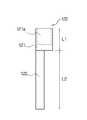
도 8은 본 발명에 따른 랩 아날로그의 평면 및 평단면도,
도 9는 본 발명에 따른 임플란트용 디지털 모델 제작 방법을 보인 예시도.1 to 8 show an embodiment of a digital model according to the present invention,
1 is an example showing an implant procedure,
FIG. 2 is an illustration showing a lab analog inserted into a model body according to the present invention,
3 is a partial cutaway cross-sectional view showing insertion of a lab analog into a model body according to the present invention,
FIG. 4 is an exemplary sectional view showing a hole formed in a model body according to the present invention,
Fig. 5 is a view showing a machining example showing the inner working form of the hole drilled by the drilling drill tool according to the milling operation of Fig. 4,
6 is a bottom perspective view showing a lab analog according to the present invention,
Figure 7 is a front view of a lab analog according to the present invention,
Figure 8 is a plan and top section view of a lab analogue according to the present invention,
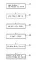
FIG. 9 is a view showing an example of a method for producing a digital model for an implant according to the present invention; FIG.
이하, 본 발명의 바람직한 실시 예를 첨부한 도면을 참조로 하여 상세히 설명한다.Hereinafter, preferred embodiments of the present invention will be described in detail with reference to the accompanying drawings.
본 발명은 이하에서 개시되는 실시 예에 한정되는 것이 아니라 서로 다른 다양한 형태로 구현될 수 있으며, 단지 본 실시 예는 본 발명의 개시가 완전하도록 하며 통상의 지식을 가진 자에게 발명의 범주를 완전하게 알려주기 위하여 제공되는 것이다.It is to be understood that the present invention is not limited to the disclosed embodiments, but may be embodied in many different forms and should not be construed as limited to the embodiments set forth herein. Rather, these embodiments are provided so that this disclosure will be thorough and complete, It is provided to inform.
이하, 본 발명의 바람직한 실시 예를 첨부된 도면들을 참조하여 상세히 설명한다. 우선 각 도면의 구성 요소들에 참조부호를 부가함에 있어서, 동일한 구성 요소들에 대해서는 비록 다른 도면상에 표시되더라도 가능한 한 동일한 부호를 가지도록 하고 있음에 유의해야 한다. 또한, 본 발명을 설명함에 있어, 관련된 공지구성 또는 기능에 대한 구체적인 설명이 본 고안의 요지를 흐릴 수 있다고 판단되는 경우에는 그 상세한 설명은 생략한다.Hereinafter, preferred embodiments of the present invention will be described in detail with reference to the accompanying drawings. In the drawings, the same reference numerals are used to designate the same or similar components throughout the drawings. In the following description of the present invention, a detailed description of known functions and configurations incorporated herein will be omitted when it may make the subject matter of the present invention rather unclear.
도 1 내지 도 8은 본 발명에 의한 임플란트용 디지털 모델을 보인 실시 예이다.1 to 8 show an embodiment of a digital model for an implant according to the present invention.
먼저, 도 1을 참조하면, 시술할 환자의 잇몸을 절개하여 치조골을 노출시킨 후에 임플란트가 식립될 위치를 결정하고, 상기 위치에 드릴과 같은 천공 도구를 사용하여 치조골(1)의 소정 위치를 천공하여 픽스츄어(2)가 식립될 구멍을 형성한다. 그리고 식립된 픽스츄어(2)가 치조골(1)과 융착되면, 상기 픽스츄어(2)에 지대주(3) 및 인공치관(4)을 결합시킨 후에 잇몸을 덮음으로써 임플란트의 설치가 완료된다.First, referring to FIG. 1, a position of an implant is determined after cutting a gum of a patient to be treated to expose an alveolar bone, and a predetermined position of the alveolar bone 1 is punctured using a perforating tool such as a drill Thereby forming holes through which the
본 발명에 따른 임플란트용 디지털 모델은 CAD/CAM에 의해 임플란트 시술을 위한 픽스츄어(2)가 삽입될 홀 구멍(111)이 가공된 모델 본체(110)와; 상기 모델 본체(110)의 홀 구멍(111)에 삽입되어 픽스츄어(2)와 동일하게 위치와 방향을 알려주도록 시뮬레이션하기 위한 랩 아날로그(120)를 포함하여 구성된다.The digital model for an implant according to the present invention includes: a
여기서 상기 랩 아날로그는 석고 모델에 사용되는 것과 3D 프린터에 사용되는 것이 있다.Here, the lab analog is used for a plaster model and for a 3D printer.
먼저, 랩 아날로그를 석고 모형에서 사용시에는 환자의 구강 내에 이미 식립된 픽스츄어위에 임플란트 인상 채득을 위한 임프레션 코핑을 삽입한 후 인상체를 부어 인상체를 채득하고, 임프레션 코핑에 랩 아날로그를 삽입하여 석고 모형을 제작하여 사용이 가능하다. 이때 석고 모형에 식립된 랩 아날로그는 구강내의 식립된 픽스츄어의 역할을 하게 된다.First, when the lab analog is used in the plaster model, the impression copings for implant impression preparation are inserted on the fixture already placed in the oral cavity of the patient, the impression body is poured to obtain the impression body, and the lap analog is inserted into the impression coping, It can be used by making a model. At this time, the lab analog embedded in the gypsum model serves as a fixture placed in the oral cavity.
또한 3D 프린터용으로 디지털 모델을 제작하기 위해서는 구강 내의 픽스츄어에 스캔바디를 삽입하고, 스캐너를 이용하여 구강을 스캔한 후, 스캔 데이터로부터 스캔 시 사용한 스캔바디의 스펙(방향, 형상)을 알면 픽스츄어의 위치와 방향을 추론할 수 있다. 3D printer용 디지털 모델 디자인은 랩 아날로그의 스펙(상품명과 형상)을 지정하면 위에서 추론된 픽스츄어의 위치와 방향 정보를 이용하여 랩 아날로그가 픽스츄어를 잘 모사 할 수 있도록 3D printer용 디지털 모델을 디자인할 수 있다.In order to produce a digital model for a 3D printer, a scan body is inserted into a fixture in the mouth, a mouth is scanned using a scanner, and a specification (direction, shape) The position and orientation of the tip can be deduced. The digital model design for the 3D printer is designed to design a digital printer model for the 3D printer so that the lab analog can accurately simulate the fixture by using the position and orientation information of the picked-up rectifier specified above (specification of product name and shape) can do.
도 3 내지 도 4를 참조하면, 상기 홀 구멍(111)은 상기 랩 아날로그(120)의 형상에 맞대응하는 형태의 천공된 홀 구조로서, 상기 홀 구멍(111)은 CAD/CAM에 의해 가공되는 상단 가공부(112)와; 상기 상단 가공부(112) 보다 그 내경이 좁게 가공되는 하단 가공부(113)를 포함하여 구성할 수 있다.3 to 4, the
여기서 상단 가공부(112)를 형성함에 있어서 도 8을 참조하여 설명하면, 상단 가공부(112)의 상부측 공간(S)은 볼앤드밀(130)로 가공하고, 상단 가공부(112)의 하부측 가공 밑단부(112a)는 플랫앤드밀(130A)로 직각 가공하는 형태로서, 디지털 모델에서 랩 아날로그가 삽입될 홀 부분을 볼앤드밀, 플랫앤드밀이 조합된 도구로 가공 처리할 수 있다.8, the upper side space S of the
또한, 상기 랩 아날로그(120)는 밀링 방식에 의해 가공되는 부품 형태로서, 상측으로 큰 외경을 갖도록 형성되는 상부 원통부(121)와; 상기 상부 원통부(121)에서 하측으로 연장 형성되어 작은 외경을 갖도록 형성되는 하부 원통부(122)를 포함하여 구성하게 된다.In addition, the
또한 상기 상부 원통부(121)는 그 상부면 내측에 지대주(3)의 종류나 체결 형상에 따른 돌기에 대응 형상으로 가공된 중공(121a)을 갖도록 형성할 수 있다.In addition, the upper
더불어 상기 중공(121a)의 내부는 지대주의 하부 돌기 형태에 따른 사각이나 육각 형태 등의 형상을 갖도록 형성되어 지대주의 돌기와 맞대응하는 구조로 체결이 가능하며, 상기 지대주의 돌기 길이와 중공의 깊이는 같도록 형성되어 체결을 견고하게 하는 것이 바람직하다.In addition, the inside of the hollow 121a is shaped to have a square or hexagonal shape corresponding to the shape of the lower projection of the abutment, and can be fastened with a structure corresponding to the projection of the abutment. The length of the abutment and the depth of the hollow are the same So that the fastening is firmly established.
여기서 스캔 된 상기 홀 구멍을 통하여 디지털 모델 디자인에 따른 랩 아날로그의 스펙(상품명과 형상)을 지정하여 랩 아날로그가 삽입될 수 있도록 하는 디지털 모델을 디자인할 수 있다.Here, a digital model can be designed to allow the lab analog to be inserted by designating the specifications (product name and shape) of the lab analog according to the digital model design through the hole that has been scanned.
한편, 도 6에 도시된 바와 같이 상기 랩 아날로그는 상기 상부 원통부(121)와 연결되는 하부 원통부(122)는 상기 상부 원통부(121)의 중심보다 그 중심이 어느 한쪽으로 편심되도록 형성할 수 있다. 이로써, 편심량은 인공치아(크라운)의 방향을 결정하는데 사용하게 된다.6, the lower analog
더불어, 상기 상부 원통부(121)의 수직 길이(L1)가 상기 하부 원통부 보다 짧게 형성되고, 상기 하부 원통부(122)의 수직 길이(L2)가 상부 원통부 보다 더 길게 형성할 수 있다.In addition, the vertical length L1 of the upper
여기서 상기 홀 구멍(111)에 삽입되는 랩 아날로그(120)는 편심된 상부 원통부(121)와 하부 원통부(122)의 위치에 따라 픽스츄어의 삽입 방향을 판단할 수 있다.Here, the
또한, 상기 랩 아날로그(120)의 하부 원통부(122)의 삽입 위치에 따라 픽스츄어의 삽입 깊이나 기울임 정도를 판단할 수 있다.Further, the insertion depth of the fixture and the degree of inclination of the fixture can be determined according to the insertion position of the lower
한편, 본 발명은 임플란트용 디지털 모델 제작 방법을 개시할 수 있다.On the other hand, the present invention can disclose a digital model production method for an implant.
도 9는 본 발명에 의한 임플란트용 디지털 모델 제작 방법을 보인 실시 예이다.9 is an embodiment showing a method of manufacturing a digital model for an implant according to the present invention.
치아 디지털 모델은 구강 스캐너, 임프레션 스캐너, 석고 모델 스캐너로부터 얻은 데이터를 이용하여 치아 디지털 모델을 제작할 수 있으며, 구강 스캐너로부터 얻은 데이터로부터 디지털 모델을 제작하는 방식이 가장 간단하다.Tooth digital models can produce tooth digital models using data from oral scanners, impression scanners, and gypsum model scanners, and the simplest way to create digital models from data from oral scanners.
< 실시예 1: 석고 모델 스캐너로부터 디지털 모델을 얻는 과정 >≪ Example 1: Procedure for obtaining a digital model from a gypsum model scanner >
1) 피시술자의 구강 내의 시술하고자 하는 치주골에 픽스츄어를 식립한다.1) Place a fixture on the periodontal bone to be treated in the mouth of the client.
2) 상기 픽스츄어의 상부에 제공된 수용홈에 임프레션 코핑을 삽입 고정한다.2) The impression copings are inserted and fixed in the receiving grooves provided on the top of the fixture.
3) 상기 임프레션 코핑은 물론 자연 치아의 위에 인상재를 씌워 치아 형태의 본을 뜬 인상체(미도시)를 채득한다.3) Impression material is coated on the natural tooth as well as the above-mentioned impression coping to obtain a tooth-shaped bone impressed body (not shown).
4) 인상체에는 치아 형태의 치아홈이 형성됨과 동시에 임프레션 코핑이 매립되어 있으며 임프레션 코핑의 하단부에는 랩 아날로그를 수용할 돌기부가 형성되어 있다.4) In the impression body, teeth-shaped tooth grooves are formed and impression copings are embedded. At the lower end of the impression copings, protrusions for accommodating lab analog are formed.
5) 랩 아날로그를 인상체의 임프레션 코핑의 돌기부에 장착한다.5) Attach rap analog to the protrusion of the impression coping of the impression body.
특히, 랩 아날로그의 상부에 중공형태의 체결부가 중앙에 형성되어 있으므로, 지대주에 형성된 돌기는 랩 아날로그의 중공에 수용된다.Particularly, since the hollow type fastening portion is formed at the center of the lab analog, the protrusion formed on the abutment is housed in the hollow of the lab analog.
6) 랩 아날로그가 인상체의 임프레션 코핑에 결합된 상태에서 인상체에 치과용 경석고를 부어 치아 모형의 석고 모델을 제작한다.6) With the lab analog attached to the impression coping of the impression, pour the dental gypsum on the impression body to make a tooth model of the tooth model.
7) 이때, 임프레션을 석고 모델로부터 탈착하면 랩 아날로그의 인공치아를 착탈할 수 있는 부분이 석고 치아 모형의 잇몸영역으로부터 돌출하게 된다.7) At this time, when the impression is detached from the gypsum model, a portion capable of attaching and detaching the artificial tooth of the lap analogue protrudes from the gingival region of the gypsum model.
8) 디지털 치아 모델 데이터를 얻기 위하여 스캔 바디를 석고 모델의 랩 아날로그에 고정한다.8) To obtain the digital tooth model data, the scan body is fixed to the lab analog of the gypsum model.
9) 모델 스캐너를 이용하여 스캔하여 3차원 모델링 파일을 얻는다.9) Scan with a model scanner to obtain a three-dimensional modeling file.
10) 이렇게 얻은 스캔 데이터 상에서 스캔 바디의 스캔 정보와 사전에 보유하고 있는 스캔 바디에 대한 기하학적인 데이터를 바탕으로 식립된 픽스츄어에 대한 정확한 위치 및 방향 정보를 추출할 수 있다.10) Based on the scan data of the scan body and the geometric data of the scan body stored in the scan data, accurate position and orientation information of the fixture can be extracted.
11) 이렇게 추출된 픽스츄어의 정확한 기하학적 정보를 바탕으로 CAD의 모델 빌더를 사용하여 치아 디지털 모델을 설계하고 디지털 모델에서 픽스츄어의 위치에 랩 아날로그가 삽입될 있도록 홀 구멍을 형성하는 스틸 파일을 만들어 주고 홀 구멍에 대한 정보를 CAM 제공하여 랩 아날로그가 삽입될 수 있는 홀 구멍(111)이 가공된 모델 본체(110)를 디자인 및 가공한다.11) Based on the exact geometric information of the extracted fixture, we design a digital tooth model using the CAD model builder and a steel file that forms the hole so that the lab analog is inserted at the fixture position in the digital model And the information about the hole is CAM to design and process the
12) 밀링 방식에 의해 가공되는 부품 형태로서 상기 홀 구멍에 삽입되는 랩 아날로그를 가공한다.12) A lap analog inserted into the hole is processed as a part type processed by a milling method.
13) 정확한 임플란트 고정구멍 정보를 바탕으로 성형한 모델 본체(110)의 홀 구멍(111)에 지대주와 결합할 랩 아날로그(120)를 장착한다.13) The
14) 상기 홀 구멍에 정확하게 삽입된 랩 아날로그의 상부 홈에 성형한 지대주 및 인공치아를 장착 후 형합 검사를 완료한다.14) After the abutment and artificial tooth formed in the upper groove of the lab analog inserted correctly in the hole are mounted, the coupling test is completed.
< 실시예 2: 임프레션 스캐너로부터 디지털 모델을 얻는 과정 >≪ Embodiment 2: Process of Obtaining Digital Model from Impression Scanner >
1) 피시술자의 구강 내의 시술하고자 하는 치주골에 픽스츄어를 식립한다.1) Place a fixture on the periodontal bone to be treated in the mouth of the client.
2) 상기 픽스츄어의 상부에 제공된 수용홈에 스캔 어벗트먼트를 삽입 고정한다.2) Scanning patches are inserted and fixed in the receiving grooves provided on the top of the fixture.
3) 상기 스캔 어벗트먼트는 물론 자연 치아의 위에 인상재를 씌워 치아 형태 및 스캔 어벗트먼트의 본을 뜬 인상체(미도시)를 채득한다.3) Impression material is placed on the natural tooth as well as the scan anatomy to obtain a sculpture (not shown) on which a tooth pattern and a pattern of scan specimens are formed.
4) 인상체에는 치아 형태의 치아홈과 동시에 스캔 어벗트먼트의 형태의 홈이 형성되어 있다.4) In the impression body, a tooth groove in the form of a tooth and a groove in the shape of a scan partner are formed at the same time.
5) 임프레션 스캐너로 인상체(임프레션)를 3차원 스캔하여 3차원 모델링 파일을 얻는다.5) The impression scanner (impression) is scanned three-dimensionally by the impression scanner to obtain the three-dimensional modeling file.
6) 이렇게 얻은 스캔 데이터 상에서 스캔 어벗트먼트의 스캔 정보와 사전에 보유하고 있는 스캔 어벗트먼트에 대한 기하학적인 데이터를 바탕으로 식립된 픽스츄어에 대한 정확한 위치 및 방향 정보를 추출할 수 있다.6) Based on the scanned data of the scanned patches and the geometric data of the scanned patches held on the scanned data, accurate position and orientation information of the placed fixtures can be extracted.
7) 이렇게 추출된 픽스츄어의 정확한 기하학적 정보를 바탕으로 CAD의 모델 빌더를 사용하여 치아 디지털 모델을 설계하고 디지털 모델에서 픽스츄어의 위치에 랩 아날로그가 삽입될 있도록 홀 구멍을 형성하는 스틸 파일을 만들어 주고 홀 구멍에 대한 정보를 CAM 제공하여 랩 아날로그가 삽입될 수 있는 홀 구멍(111)이 가공된 모델 본체(110)를 디자인 및 가공한다.7) Based on the precise geometric information of the extracted fixture, we design a digital tooth model using the CAD model builder and a steel file that forms the hole so that the lab analog is inserted at the fixture position in the digital model And the information about the hole is CAM to design and process the
8) 밀링 방식에 의해 가공되는 부품 형태로서 상기 홀 구멍에 삽입되는 랩 아날로그를 가공한다.8) Lap analog inserted into the hole is processed as a part type processed by the milling method.
9) 정확한 임플란트 고정구멍 정보를 바탕으로 성형한 모델 본체(110)의 홀 구멍(111)에 지대주와 결합될 랩 아날로그(120)를 장착한다.9) The
10) 상기 홀 구멍에 정확하게 삽입된 랩 아날로그의 상부 홈에 성형한 지대주 및 인공치아를 장착 후 형합 검사를 완료한다.10) After the abutment and the artificial tooth formed in the upper groove of the lab analog inserted correctly in the hole are mounted, the coupling test is completed.
< 실시예 3: 구강 스캐너로부터 디지털 모델을 얻는 과정 >≪ Embodiment 3: Procedure for Obtaining Digital Model from Oral Scanner >
1) 피시술자의 구강 내의 시술하고자 하는 치주골에 픽스츄어를 식립한 후, 상기 픽스츄어의 상부에 제공된 수용홈에 스캔 어벗트먼트를 삽입 고정한다(S1).1) A fixture is placed on a periodontal bone to be treated in the mouth of a client, and then a scan mask is inserted and fixed in the receiving groove provided on the top of the fixture (S1).
2) 구강 스캐너로 3차원 스캔하여 3차원 모델링 파일을 얻는다(S2).2) Three-dimensional scanning is performed with an oral scanner to obtain a three-dimensional modeling file (S2).
이렇게 얻은 스캔 데이터 상에서 스캔 어벗트먼트의 스캔 정보와 사전에 보유하고 있는 스캔 어벗트먼트에 대한 기하학적인 데이터를 바탕으로 식립된 픽스츄어에 대한 정확한 위치 및 방향 정보를 추출할 수 있다.Based on the scan information of the scan specimen and the geometric data of the scan specimen held on the scanner, the accurate position and orientation information of the fixture can be extracted.
3) 이렇게 추출된 픽스츄어의 정확한 기하학적 정보를 바탕으로 CAD의 모델 빌더를 사용하여 치아 디지털 모델을 설계하고 디지털 모델에서 픽스츄어의 위치에 랩 아날로그가 삽입될 있도록 홀 구멍을 형성하는 스틸 파일을 만들어 주고 홀 구멍에 대한 정보를 CAM 제공하여 랩 아날로그가 삽입될 수 있는 홀 구멍(111)이 가공된 모델 본체(110)를 디자인 및 가공한다(S3).3) Based on the accurate geometric information of the extracted fixture, we design a digital tooth model using the CAD model builder, and make a still file to form the hole hole so that the lab analog is inserted at the fixture position in the digital model The
6) 밀링 방식에 의해 가공되는 부품 형태로서 상기 홀 구멍에 삽입되는 랩 아날로그를 가공한다(S4).6) A lap analog inserted into the hole is processed as a part type processed by the milling method (S4).
7) 정확한 임플란트 고정구멍 정보를 바탕으로 성형한 모델 본체(110)의 홀 구멍(111)에 지대주와 결합될 랩 아날로그(120)를 장착한다(S5).7) The
8) 상기 홀 구멍에 정확하게 삽입된 랩 아날로그의 상부 홈에 성형한 지대주 및 인공치아를 장착 후 형합 검사를 완료한다(S6).8) After the abutment and the artificial tooth formed in the upper groove of the lab analog inserted exactly in the hole are mounted, the joint inspection is completed (S6).
여기서, 상기 랩 아날로그의 상부 원통부의 스캔 데이터를 하부 원통부의 기둥 수직축의 끝으로 인식하여 랩 아날로그의 높이를 구하고 이를 방탕으로 삽입부 3차원 자료를 바탕으로 픽스츄어 고정 구멍의 깊이를 알 수 있으며, 원통부의 곡선면과 직선면 및 편심축을 통해 고정 구멍을 중심으로 하는 방향 데이터를 얻고, 원통면의 스캔 데이터를 바탕으로 그 중심점을 구해서 픽스츄어 고정 구멍의 위치와 방향에 관한 좌표를 알아낼 수 있다.Here, the scan data of the upper analog part of the lab analog is recognized as the end of the vertical axis of the column of the lower cylindrical part, the height of the lab analog is obtained, and the depth of the fixture fixing hole can be known based on the inserted three- It is possible to obtain the direction data about the fixing hole through the curved surface, the straight surface and the eccentric shaft of the cylindrical portion and obtain the center point based on the scan data of the cylindrical surface to find the coordinates of the position and the direction of the fixture fixing hole.
이후, 치아 모형의 지대주 아날로그의 인공치아 착탈부에 인공치아를 착탈하며, 인공치아와 랩 아날로그를 서로 맞추어 가면서, 인공치아를 치조골에 매식된 지대주에 결합할 인공치아로 기공한다.Thereafter, the artificial tooth is detached from the artificial tooth attaching portion of the abutment analog of the tooth model, and the artificial tooth is inserted into the alveolar bone, while the artificial tooth and the lab analog are aligned with each other.
이렇게 해서, 치조골에 매식된 픽스츄어에 결합할 인공치아가 완성되면, 구강 내의 치조골(1)에 매식된 픽스츄어(2)에 지대주(3)와 인공치아(4)가 결합된 보철물의 시술을 완료한다.When the artificial tooth to be bonded to the fixture immersed in the alveolar bone is thus completed, the procedure of the prosthesis in which the
본 발명은 이상에서 살펴본 바와 같이 바람직한 실시예를 들어 도시하고 설명하였으나, 상기한 실시 예에 한정되지 아니하며 본 발명의 정신을 벗어나지 않는 범위 내에서 당해 발명이 속하는 기술분야에서 통상의 지식을 가진 자에 의해 본 발명의 기술사상과 아래에 기재될 특허청구범위의 균등범위 내에서 다양한 수정 및 변형이 가능함은 물론이다.While the present invention has been particularly shown and described with reference to exemplary embodiments thereof, it is clearly understood that the same is by way of illustration and example only and is not to be taken by way of limitation, It will be understood by those skilled in the art that various changes in form and details may be made therein without departing from the spirit and scope of the present invention as defined by the appended claims and their equivalents.
1 : 치조골
2 : 픽스츄어
3 : 지대주
4 : 인공치아
110 : 모델 본체
111 : 홀 구멍
112 : 상단 가공부
113 : 하단 가공부
120 : 랩 아날로그
121 : 상부 원통부
122 : 하부 원통부1: alveolar bone
2: Fixture
3: abutment
4: Artificial teeth
110: Model body
111: hole
112: upper machining portion
113: Lower machining portion
120: Lab Analog
121: upper cylinder portion
122: lower cylinder portion
Claims (8)
Translated fromKorean상기 홀 구멍은 CAD/CAM에 의해 가공되는 상단 가공부와; 상기 상단 가공부 보다 그 내경이 좁게 가공되는 하단 가공부를 포함하며, 상기 랩 아날로그의 형상에 맞대응하는 형태의 천공 홀 구조로 이루어지며,
상기 랩 아날로그는, 밀링 방식에 의해 가공되는 부품 형태로서, 상측으로 큰 외경을 갖도록 형성되는 상부 원통부와; 상기 상부 원통부에서 하측으로 연장 형성되어 작은 외경을 갖도록 형성되는 하부 원통부를 포함하고, 상부 원통부와 연결되는 하부 원통부는 상기 상부 원통부의 중심보다 그 중심이 어느 한쪽으로 편심되도록 이루어지되,
상기 홀 구멍은, 상단 가공부의 상부측 공간은 볼앤드밀로 가공하고, 상단 가공부의 하부측 가공 밑단부는 플랫앤드밀로 직각 가공하는 형태로서, 디지털 모델에서 상기 랩 아날로그가 삽입될 홀 부분을 볼앤드밀, 플랫앤드밀이 조합된 도구로 가공 처리하여 이루어지고,
상기 홀 구멍에 삽입되는 랩 아날로그는 편심된 상부 원통부와 하부 원통부의 위치에 따라 픽스츄어의 삽입 방향을 판단할 수 있도록 되며, 상기 랩 아날로그의 하부 원통부의 삽입 위치에 따라 픽스츄어의 삽입 깊이나 기울임 정도를 판단할 수 있도록 하여 디지털 모델을 디자인할 수 있도록 이루어짐을 특징으로 하는
임플란트용 디지털 모델.
A model body in which a hole for inserting a fixture for implant treatment by CAD / CAM is machined; And a lip analog that is fit into the hole of the model body and simulates the position and direction of the fixture according to the implant procedure by the lab analog inserted in the hole, As a digital model,
Wherein the hole has an upper machining portion machined by CAD / CAM; And a lower machining portion whose inner diameter is narrower than that of the upper machining portion. The lower machining portion has a perforation hole structure corresponding to the shape of the lab analog,
The lab analog is a part type processed by a milling method and has an upper cylindrical portion formed to have a larger outer diameter toward the upper side; And a lower cylindrical portion formed to extend downward from the upper cylindrical portion and formed to have a small outer diameter, and a lower cylindrical portion connected to the upper cylindrical portion is eccentrically centered with respect to the center of the upper cylindrical portion,
In the digital model, the hole portion into which the lap analog is to be inserted may be formed in a ball-and-hole, And a flat-and-milled combination tool,
The rap analog to be inserted into the hole can determine the insertion direction of the fixture according to the position of the eccentric upper cylinder and the lower cylinder, and the insertion depth of the fixture can be determined according to the insertion position of the lower analog cylinder So that it is possible to design the digital model so that the degree of inclination can be determined
Digital model for implant.
상기 상부 원통부의 수직 길이(L1)가 상기 하부 원통부 보다 짧게 형성되고,
상기 하부 원통부의 수직 길이(L2)가 상부 원통부 보다 더 길게 형성되는 것을 특징으로 하는
임플란트용 디지털 모델.
The method according to claim 1,
The vertical length L1 of the upper cylindrical portion is formed to be shorter than the lower cylindrical portion,
And the vertical length (L2) of the lower cylindrical portion is longer than that of the upper cylindrical portion
Digital model for implant.
상기 랩 아날로그는, 밀링 방식에 의해 가공되는 상측으로 큰 외경을 갖도록 형성되는 상부 원통부와; 상기 상부 원통부에서 하측으로 연장 형성되어 작은 외경을 갖도록 형성되는 하부 원통부를 형성하고, 상부 원통부와 연결되는 하부 원통부는 상기 상부 원통부의 중심보다 그 중심이 어느 한쪽으로 편심되도록 이루어지며,
상기 홀 구멍은, 상단 가공부의 상부측 공간은 볼앤드밀로 가공하고, 상단 가공부의 하부측 가공 밑단부는 플랫앤드밀로 직각 가공하여 디지털 모델에서 상기 랩 아날로그가 삽입될 홀 부분을 볼앤드밀, 플랫앤드밀이 조합된 도구로 가공 처리하도록 이루어지고,
상기 랩 아날로그의 상부 원통부의 스캔 데이터를 하부 원통부의 기둥 수직축의 끝으로 인식하여 랩 아날로그의 높이를 구하고 이를 방탕으로 삽입부 3차원 자료를 바탕으로 픽스츄어 고정 구멍의 깊이를 알 수 있으며, 원통부의 곡선면과 직선면 및 편심축을 통해 고정 구멍을 중심으로 하는 방향 데이터를 얻고, 원통면의 스캔 데이터를 바탕으로 그 중심점을 구해서 픽스츄어 고정 구멍의 위치와 방향에 관한 좌표를 알아낼 수 있도록 하여, 상기 홀 구멍에 삽입된 랩 아날로그에 의해 임플란트 시술에 따른 픽스츄어의 위치와 방향을 구강 외부에서 동일하게 시뮬레이션할 수 있도록 이루어짐을 특징으로 하는
임플란트용 디지털 모델 제조방법.
(S1) placing a fixture on a periodontal bone to be treated in a mouth of a client and inserting and fixing a scan fitting in a receiving groove provided in an upper portion of the fixture; Dimensional scanning with an oral scanner to obtain a three-dimensional modeling file and extracting accurate position and orientation information for the placed fixture (S3); (S3) designing a model body by providing a CAM with a steel file in which a hole analog is inserted so that a lab analog can be inserted at a position of a fixture using a CAD model builder, and providing information on the hole to a CAM; (S4) machining a lab analog inserted into the hole as a part type processed by a milling method; (S5) mounting a lab analog to be combined with the abutment on the hole of the model body 110 formed on the basis of the accurate implant fixture hole information; And a step (S6) of inserting the abutment and the artificial tooth formed in the upper groove of the lab analog inserted into the hole precisely and completing the joint examination,
The lab analog includes an upper cylindrical portion formed to have a larger outer diameter toward the upper side, which is processed by a milling method; A lower cylindrical portion formed to extend downward from the upper cylindrical portion and formed to have a smaller outer diameter and a lower cylindrical portion connected to the upper cylindrical portion is eccentrically centered with respect to the center of the upper cylindrical portion,
The upper hole of the upper machining portion is machined by ball-and-hole machining, and the machining lower portion of the upper machining portion is machined at a right angle by a flat-end mill. In the digital model, hole portions into which the rap analog is inserted are ball- Processing is performed with a combined tool,
The scan data of the upper analog part of the lab analog is recognized as the end of the vertical axis of the column of the lower cylindrical part and the height of the lab analog is obtained and the depth of the fixture fixing hole can be known based on the inserted three- It is possible to obtain the direction data about the fixed hole through the curved surface, the straight surface, and the eccentric shaft, obtain the center point based on the scan data of the cylindrical surface, and find out the coordinates about the position and the direction of the fixture fixing hole, The position and direction of the fixture according to the implant procedure can be simulated equally in the oral cavity by the lab analog inserted into the hole.
A method for manufacturing a digital model for an implant.
스캔 된 상기 홀 구멍을 통하여 3D printer용 디지털 모델 디자인에 따른 랩 아날로그의 스펙을 지정하면 위에서 추론된 픽스츄어의 위치와 방향 정보를 이용하여 랩 아날로그가 픽스츄어를 잘 모사 할 수 있도록 3D printer용 디지털 모델을 디자인할 수 있도록 이루어짐을 특징으로 하는
임플란트용 디지털 모델 제조방법.8. The method of claim 7,
If the specification of the lab analog according to the digital model design for the 3D printer is designated through the hole that has been scanned, it is possible to use the position information and the direction information of the fixture derived from the above, so that the lab analog can accurately simulate the fixture. So that the model can be designed.
A method for manufacturing a digital model for an implant.
Priority Applications (1)
| Application Number | Priority Date | Filing Date | Title |
|---|---|---|---|
| KR1020160032212AKR101732466B1 (en) | 2016-03-17 | 2016-03-17 | A method of manufacturing the digital model for implant |
Applications Claiming Priority (1)
| Application Number | Priority Date | Filing Date | Title |
|---|---|---|---|
| KR1020160032212AKR101732466B1 (en) | 2016-03-17 | 2016-03-17 | A method of manufacturing the digital model for implant |
Publications (1)
| Publication Number | Publication Date |
|---|---|
| KR101732466B1true KR101732466B1 (en) | 2017-05-08 |
Family
ID=60164092
Family Applications (1)
| Application Number | Title | Priority Date | Filing Date |
|---|---|---|---|
| KR1020160032212AActiveKR101732466B1 (en) | 2016-03-17 | 2016-03-17 | A method of manufacturing the digital model for implant |
Country Status (1)
| Country | Link |
|---|---|
| KR (1) | KR101732466B1 (en) |
Citations (1)
| Publication number | Priority date | Publication date | Assignee | Title |
|---|---|---|---|---|
| JP2006043121A (en) | 2004-08-04 | 2006-02-16 | Isao Matsuno | Bracket mounting jig for orthodontic appliance and mounting jig with bracket. |
- 2016
- 2016-03-17KRKR1020160032212Apatent/KR101732466B1/enactiveActive
Patent Citations (1)
| Publication number | Priority date | Publication date | Assignee | Title |
|---|---|---|---|---|
| JP2006043121A (en) | 2004-08-04 | 2006-02-16 | Isao Matsuno | Bracket mounting jig for orthodontic appliance and mounting jig with bracket. |
Similar Documents
| Publication | Publication Date | Title |
|---|---|---|
| US12263050B2 (en) | Unitary dental model | |
| JP4399257B2 (en) | Method for manufacturing superstructure and corresponding drill jig | |
| JP6063516B2 (en) | Method for generating accurate bone and soft tissue digital dental models | |
| KR101473192B1 (en) | method of manufacturing guide stent for dental implant | |
| RU2566921C2 (en) | Removable elements carrier in dental model made by computer-aided production facilities | |
| KR101638558B1 (en) | digital onebody abutment for dental implant using digital library | |
| KR101546531B1 (en) | Digital healing abutment | |
| CN111970991B (en) | Scanning jig, method and system for determining spatial position of plant and the like | |
| US20120088208A1 (en) | Method for Defining a Dental Framework Design Volume | |
| US10874490B2 (en) | Method for producing a dental prosthesis with parallel roots of the prosthetic teeth | |
| KR20130137095A (en) | Methods for producing a laboratory analogue for dental implants | |
| KR101554158B1 (en) | method for manufacturing surgical guide of dental implant using cloud system | |
| EP3750506B1 (en) | Denture system and method for manufacturing a denture | |
| KR20120136858A (en) | Rapid prototype of oral model assembly for fabricating intraoral appliance used for implant operation and method for fabricating intraoral appliance used for implant operation using the same | |
| US20130065195A1 (en) | Method for manufacturing a template for providing dental implants in a jaw and scan prosthesis for applying this method | |
| JP2020526304A (en) | Digital prosthetic manufacturing method and manufacturing system, denture hole guider and manufacturing method applied to it | |
| KR101732466B1 (en) | A method of manufacturing the digital model for implant | |
| JP5937401B2 (en) | Scanning jig | |
| KR20110083975A (en) | Useful methods, systems and accessories for dental implant related procedures | |
| KR20100009162A (en) | Fixture in an implant stent for accurate guidance-insertion | |
| JP2014198132A (en) | Scanning instrument | |
| CN110099650A (en) | Artificial tooth | |
| JP2013102929A (en) | System for embedding artificial tooth root | |
| JP2011501998A (en) | Stent fixture for implants for precision guided planting | |
| KR20190117069A (en) | Synchronization plate having a function of machining calibration |
Legal Events
| Date | Code | Title | Description |
|---|---|---|---|
| PA0109 | Patent application | Patent event code:PA01091R01D Comment text:Patent Application Patent event date:20160317 | |
| PA0201 | Request for examination | ||
| PE0902 | Notice of grounds for rejection | Comment text:Notification of reason for refusal Patent event date:20161130 Patent event code:PE09021S01D | |
| E701 | Decision to grant or registration of patent right | ||
| PE0701 | Decision of registration | Patent event code:PE07011S01D Comment text:Decision to Grant Registration Patent event date:20170424 | |
| GRNT | Written decision to grant | ||
| PR0701 | Registration of establishment | Comment text:Registration of Establishment Patent event date:20170426 Patent event code:PR07011E01D | |
| PR1002 | Payment of registration fee | Payment date:20170426 End annual number:3 Start annual number:1 | |
| PG1601 | Publication of registration | ||
| PR1001 | Payment of annual fee | Payment date:20200401 Start annual number:4 End annual number:4 | |
| PR1001 | Payment of annual fee | Payment date:20240415 Start annual number:8 End annual number:8 |