KR101731969B1 - Surgical instrument - Google Patents
Surgical instrumentDownload PDFInfo
- Publication number
- KR101731969B1 KR101731969B1KR1020100122947AKR20100122947AKR101731969B1KR 101731969 B1KR101731969 B1KR 101731969B1KR 1020100122947 AKR1020100122947 AKR 1020100122947AKR 20100122947 AKR20100122947 AKR 20100122947AKR 101731969 B1KR101731969 B1KR 101731969B1
- Authority
- KR
- South Korea
- Prior art keywords
- frame
- link
- housing
- rotatably
- regulating
- Prior art date
- Legal status (The legal status is an assumption and is not a legal conclusion. Google has not performed a legal analysis and makes no representation as to the accuracy of the status listed.)
- Expired - Fee Related
Links
Images


Classifications
- A—HUMAN NECESSITIES
- A61—MEDICAL OR VETERINARY SCIENCE; HYGIENE
- A61B—DIAGNOSIS; SURGERY; IDENTIFICATION
- A61B17/00—Surgical instruments, devices or methods
- A61B17/28—Surgical forceps
- A61B17/29—Forceps for use in minimally invasive surgery
- A—HUMAN NECESSITIES
- A61—MEDICAL OR VETERINARY SCIENCE; HYGIENE
- A61B—DIAGNOSIS; SURGERY; IDENTIFICATION
- A61B34/00—Computer-aided surgery; Manipulators or robots specially adapted for use in surgery
- A61B34/30—Surgical robots
- A—HUMAN NECESSITIES
- A61—MEDICAL OR VETERINARY SCIENCE; HYGIENE
- A61B—DIAGNOSIS; SURGERY; IDENTIFICATION
- A61B34/00—Computer-aided surgery; Manipulators or robots specially adapted for use in surgery
- A61B34/70—Manipulators specially adapted for use in surgery
- A—HUMAN NECESSITIES
- A61—MEDICAL OR VETERINARY SCIENCE; HYGIENE
- A61B—DIAGNOSIS; SURGERY; IDENTIFICATION
- A61B34/00—Computer-aided surgery; Manipulators or robots specially adapted for use in surgery
- A61B34/70—Manipulators specially adapted for use in surgery
- A61B34/71—Manipulators operated by drive cable mechanisms
- A—HUMAN NECESSITIES
- A61—MEDICAL OR VETERINARY SCIENCE; HYGIENE
- A61B—DIAGNOSIS; SURGERY; IDENTIFICATION
- A61B17/00—Surgical instruments, devices or methods
- A61B2017/00367—Details of actuation of instruments, e.g. relations between pushing buttons, or the like, and activation of the tool, working tip, or the like
- A61B2017/00398—Details of actuation of instruments, e.g. relations between pushing buttons, or the like, and activation of the tool, working tip, or the like using powered actuators, e.g. stepper motors, solenoids
- A61B2017/00402—Piezo electric actuators
- A—HUMAN NECESSITIES
- A61—MEDICAL OR VETERINARY SCIENCE; HYGIENE
- A61B—DIAGNOSIS; SURGERY; IDENTIFICATION
- A61B17/00—Surgical instruments, devices or methods
- A61B17/28—Surgical forceps
- A61B17/29—Forceps for use in minimally invasive surgery
- A61B2017/2901—Details of shaft
- A61B2017/2902—Details of shaft characterized by features of the actuating rod
- A—HUMAN NECESSITIES
- A61—MEDICAL OR VETERINARY SCIENCE; HYGIENE
- A61B—DIAGNOSIS; SURGERY; IDENTIFICATION
- A61B17/00—Surgical instruments, devices or methods
- A61B17/28—Surgical forceps
- A61B17/29—Forceps for use in minimally invasive surgery
- A61B2017/2901—Details of shaft
- A61B2017/2906—Multiple forceps
- A—HUMAN NECESSITIES
- A61—MEDICAL OR VETERINARY SCIENCE; HYGIENE
- A61B—DIAGNOSIS; SURGERY; IDENTIFICATION
- A61B17/00—Surgical instruments, devices or methods
- A61B17/28—Surgical forceps
- A61B17/29—Forceps for use in minimally invasive surgery
- A61B2017/2901—Details of shaft
- A61B2017/2908—Multiple segments connected by articulations
- A—HUMAN NECESSITIES
- A61—MEDICAL OR VETERINARY SCIENCE; HYGIENE
- A61B—DIAGNOSIS; SURGERY; IDENTIFICATION
- A61B17/00—Surgical instruments, devices or methods
- A61B17/28—Surgical forceps
- A61B17/29—Forceps for use in minimally invasive surgery
- A61B2017/2926—Details of heads or jaws
- A61B2017/2927—Details of heads or jaws the angular position of the head being adjustable with respect to the shaft
Landscapes
- Health & Medical Sciences (AREA)
- Surgery (AREA)
- Life Sciences & Earth Sciences (AREA)
- Engineering & Computer Science (AREA)
- Medical Informatics (AREA)
- Biomedical Technology (AREA)
- Heart & Thoracic Surgery (AREA)
- Nuclear Medicine, Radiotherapy & Molecular Imaging (AREA)
- Molecular Biology (AREA)
- Animal Behavior & Ethology (AREA)
- General Health & Medical Sciences (AREA)
- Public Health (AREA)
- Veterinary Medicine (AREA)
- Robotics (AREA)
- Ophthalmology & Optometry (AREA)
- Manipulator (AREA)
- Surgical Instruments (AREA)
Abstract
Translated fromKoreanDescription
Translated fromKorean최소 침습 수술 등에 활용될 수 있는 수술 도구에 관한 것이다.Minimally invasive surgery, and the like.
최소 침습 수술은 몇 개의 작은 절개부를 통해 수술 도구를 삽입하여 수술을 수행함으로써 수술로 인한 절개를 최소화하는 수술 기법이다. 이러한 최소 침습 수술은 수술 후에 일어나는 환자의 대사 과정의 변화를 상대적으로 감소시킬 수 있으므로, 환자의 회복 기간을 짧게 하는 데에 도움이 된다.Minimally invasive surgery is a surgical technique that minimizes the incision by surgery by inserting surgical instruments through several small incisions. Such minimally invasive surgery can reduce the metabolic process of the patient after the surgery relatively, thus helping to shorten the patient's recovery period.
따라서, 최소 침습 수술을 적용하면, 환자의 수술 후의 입원 기간도 단축되며, 환자가 수술 후 짧은 시일 내에 정상적인 생활로 복귀할 수 있게 된다. 또한, 최소 침습 수술을 통해, 환자가 느끼는 통증을 경감하는 한편, 수술 후 환자에게 남는 흉터를 줄일 수도 있게 된다.Therefore, when minimally invasive surgery is applied, the patient's post-operative hospitalization period is shortened and the patient can return to normal life within a short time after the operation. In addition, through minimally invasive surgery, it is possible to alleviate the pain felt by the patient while reducing scarring remaining in the patient after the operation.
최소 침습 수술의 가장 일반적인 형태가 복강 내에서 최소 침습 조사와 수술을 하는 복강경 수술이다. 복강경 수술을 수행할 때, 보다 더 환자에게 수술의 고통을 경감시켜 주고, 수술 성공률을 높여주기 위해 수술 로봇이 활용된다.The most common form of minimally invasive surgery is laparoscopic surgery with minimally invasive irradiation and surgery within the abdominal cavity. When performing laparoscopic surgery, surgical robots are used to further alleviate the pain of the operation to the patient and increase the success rate of the operation.
수술 로봇은 수술 전 준비 단계에서 수동으로 움직이는 패시브 암(passive arm)과 수술시 운전자의 동작에 따라 운동하는 액티브 암(active arm), 손목과 집게로 직접적인 수술을 하는 수술 도구로 구성된다. 수술 도구의 운동과 힘을 전달하기 위해 와이어가 이용되며, 와이어를 구동시키는 구동기가 액티브 암에 구비된다.The surgical robot consists of a passive arm that moves manually in preparation for an operation, an active arm that moves according to the driver's movement during surgery, and a surgical tool that performs direct surgery with a wrist and a forceps. A wire is used to transmit the motion and force of the surgical tool, and a driver for driving the wire is provided in the active arm.
수술 로봇의 크기가 감소될 수 있고, 다관절 구조로 확장이 용이한 수술 도구를 제시한다.We propose a surgical tool that can reduce the size of the surgical robot and can easily be expanded into a multi - jointed structure.
상기의 과제를 달성하기 위한 수술 도구는, 수술 부위에 대해 수술 작업을 수행하는 엔드 이펙터(end effecter); 상기 엔드 이펙터가 운동할 수 있도록 상기 엔드 이펙터에 동력을 전달하는 동력 전달부; 상기 동력 전달부를 감싸는 하우징; 및 상기 하우징 내에 수용되어 상기 동력 전달부에 동력을 제공하는 압전 구동기를 포함한다.An operation tool for accomplishing the above object includes an end effector for performing a surgical operation on a surgical site; A power transmission unit for transmitting power to the end effector so that the end effector can move; A housing surrounding the power transmission unit; And a piezoelectric actuator accommodated in the housing to provide power to the power transmission portion.
수술 도구는 압전 구동기가 하우징의 내부에 설치되는 구성을 가지므로, 와이어를 구동시키는 모터 등의 구동기가 수술 도구의 외부에 설치되는 구성과 비교하여, 수술 로봇의 크기를 감소시킬 수 있다. 또한, 수술 도구가 압전 구동기에 의해 엔드 이펙터를 구동하므로, MR(Magnetic Resonance) 환경에서도 사용 가능하다.Since the surgical tool has a configuration in which the piezoelectric actuator is installed inside the housing, the size of the surgical robot can be reduced as compared with a configuration in which a driver such as a motor for driving the wire is installed outside the surgical tool. Further, since the surgical tool drives the end effector by the piezoelectric actuator, it can be used in an MR (magnetic resonance) environment.
또한, 수술 도구는 다관절로 구성될 경우, 관절 별로 독립적인 운동 제어가 가능하다. 관절수가 증가하더라도 다른 관절에 영향을 주지 않게 되므로, 다관절 구조로 확장이 용이해질 수 있다.In addition, when the surgical tool is composed of multiple joints, independent motion control can be performed for each joint. The increase in the number of joints does not affect the other joints, so that the joints can be easily expanded.
도 1은 수술 도구의 일 예에 대한 사시도.
도 2는 도 1에 있어서, 하우징 내에 수용된 동력 전달부 및 압전 구동기의 일 예에 대한 개략적인 구성도.
도 3은 도 2의 압전 구동기를 발췌하여 도시한 사시도.
도 4는 압전 구동기의 다른 예에 대한 개략적인 구성도.
도 5는 도 1에 있어서, 2-자유도 회전 매커니즘을 갖는 수술 도구의 내부를 일부 도시한 사시도.
도 6a 및 도 6b는 도 5에 있어서, 엔드 이펙터가 제1축 방향으로 굽힘 동작하는 과정을 설명하기 위한 단면도.
도 7a 및 도 7b는 도 5에 있어서, 엔드 이펙터가 제2축 방향으로 굽힘 동작하는 과정을 설명하기 위한 단면도.
도 8은 복수의 엔드 이펙터를 구비한 예를 도시한 사시도.
도 9는 동력 전달부 및 압전 구동기의 또 다른 예에 대한 개략적인 구성도.
도 10은 도 9의 압전 구동기를 발췌하여 도시한 사시도.1 is a perspective view of an example of a surgical tool.
Fig. 2 is a schematic configuration diagram of an example of a power transmitting portion and a piezoelectric actuator housed in a housing in Fig. 1; Fig.
Fig. 3 is a perspective view illustrating the piezoelectric actuator of Fig. 2 taken as an excerpt. Fig.
4 is a schematic structural view of another example of the piezoelectric actuator.
FIG. 5 is a perspective view of the inside of a surgical tool having a two-degree-of-freedom rotating mechanism in FIG. 1; FIG.
6A and 6B are sectional views for explaining a process of bending the end effector in the first axial direction in Fig.
7A and 7B are sectional views for explaining the process of bending the end effector in the second axial direction in Fig.
8 is a perspective view showing an example having a plurality of end effectors.
9 is a schematic structural view of another example of the power transmitting portion and the piezoelectric actuator.
10 is a perspective view showing an excerpt of the piezoelectric actuator of Fig.
도 1은 수술 도구의 일 예에 대한 사시도이다. 도 2는 도 1에 있어서, 수술 도구 내에 수용된 동력 전달부 및 압전 구동기의 일 예에 대한 개략적인 구성도이다.1 is a perspective view of an example of a surgical tool. Fig. 2 is a schematic configuration diagram of an example of a power transmitting portion and a piezoelectric actuator housed in a surgical tool in Fig. 1. Fig.
도 1 및 도 2를 참조하면, 수술 도구는 수술 로봇에 채용되어 최소 침습 수술 등을 수행하는 것으로, 엔드 이펙터(end effecter, 110)와, 동력 전달부(120)와, 하우징(130), 및 압전 구동기(140)를 포함한다.1 and 2, the surgical tool is employed in a surgical robot to perform minimally invasive surgery or the like, and includes an
엔드 이펙터(110)는 수술 부위에 직접 접촉되어 수술 부위에 대한 수술 작업을 수행한다. 동력 전달부(120)는 엔드 이펙터(110)가 운동할 수 있도록 압전 구동기(140)의 동력을 엔드 이펙터(110)에 전달한다. 하우징(130)은 동력 전달부(120)를 감싸는 구조로 이루어진다. 압전 구동기(140)는 전위차가 가해질 때 응력을 발생시키는 압전 소자의 역압전 효과를 이용하여, 기계적인 동력을 발생시킨다. 압전 구동기(140)는 소형화가 가능하다. 따라서, 압전 구동기(140)는 하우징(130) 내에 수용되어 동력 전달부(120)에 동력을 제공할 수 있다.The
전술한 바와 같이, 압전 구동기(140)는 수술 도구의 내부, 즉 하우징(130)의 내부에 설치되는 구성을 가지므로, 와이어를 구동시키는 전자력 모터 등의 구동기가 수술 도구의 외부에 설치되는 구성과 비교하여, 수술 로봇의 크기를 감소시킬 수 있다. 또한, 수술 도구가 압전 구동기(140)에 의해 엔드 이펙터(110)를 구동하므로, MR(Magnetic Resonance) 환경에서도 사용 가능하다.As described above, since the
동력 전달부(120)는 일 예로서, 선형 동작함에 따라 엔드 이펙터(110)에 동력을 전달하는 슬라이더(121)를 포함한다. 슬라이더(121)는 강체(rigid body)로 이루어질 수 있다. 따라서, 동력 전달부로 와이어가 이용되는 것에 비해, 백래쉬(backlash)가 없어 정확한 제어가 가능하며, 장시간 사용에도 늘어남 없이 수명이 증가할 수 있다. 여기서, 압전 구동기(140)는 슬라이더(121)의 둘레에 배치되도록 하우징(130) 내에 장착되어 슬라이더(121)를 선형 동작시킨다. 예를 들어, 도 3에 도시된 바와 같이, 압전 구동기(140)는 서포터(141)와, 한 쌍의 압전 소자(142)들, 및 탄력부(143)를 포함한다.The power transmitting
서포터(141)는 하우징(130)의 내벽에 고정된다. 한 쌍의 압전 소자(142)들은 서포터(141) 상에 서로 이격되어 배치된다. 압전 소자(142)는 압전 세라믹 등일 수 있다. 탄력부(143)는 한 쌍의 탄성체(143a)들과, 고정 돌기(143b)들, 및 커플링 팁(143c)을 구비한다.The
한 쌍의 탄성체(143a)들은 압전 소자(142)들에 각각 고정되고 서로 이격되어 배치된다. 고정 돌기(143b)들은 탄성체(143a)들을 압전 소자(142)들과 함께 서포터(141)에 각각 고정시키기 위한 것이다. 각각의 고정 돌기(143b)는 일단부가 탄성체(14a)에 연결되고 타단부가 서포터(141)에 고정되도록 형성된다. 커플링 팁(143c)은 탄성체(143)들를 연결하며 슬라이더(121)에 접촉되도록 형성된다.The pair of
전술한 압전 구동기(140)는 다음과 같이 작용한다. 압전 소자(142)들 간에 서로 반대되는 변위가 발생하도록 전압을 인가하면, 커플링 팁(143c)에 소용돌이 형태의 진동이 발생하게 된다. 이때, 커플링 팁(143c)의 진동 방향은 압전 소자(142)들에 인가되는 전압 방향에 따라 정방향 또는 역방향으로 설정된다. 커플링 팁(143c)의 진동 방향에 따라 커플링 팁(143c)에는 슬라이더(121)를 전진 또는 후진시키는 힘이 작용하게 된다. 따라서, 슬라이더(121)가 전진 또는 후진할 수 있게 된다. 압전 구동기(140)는 슬라이더(121)에 제공되는 동력을 증가시키기 위해 복수 개로 구비되어 슬라이더(121) 둘레에 배치될 수 있다.The
동력 전달부(120)는 엔드 이펙터(110)에 독립된 동력들을 전달하도록 복수의 슬라이더(121)들을 포함할 수 있다. 슬라이더(121)들은 병렬로 선형 동작함에 따라 엔드 이펙터(110)에 각각 동력을 전달하도록 배치된다. 이 경우, 압전 구동기(140)는 슬라이더(121)들의 각 둘레에 배치되도록 하우징(130) 내에 장착되어 슬라이더들을 독립적으로 선형 동작시킨다. 각각의 압전 구동기(140)는 전술한 예와 같이 구성될 수 있다.The
다른 예로, 도 4에 도시된 바와 같이, 압전 구동기(240)는 관성저항 부재(241)와, 마찰 샤프트(242), 및 압전 소자(243)를 포함할 수 있다. 관성저항 부재(241)는 슬라이더(121)의 일단에 고정된다. 마찰 샤프트(242)는 관성저항 부재(241)를 관통하여 관성저항 부재(241)와 마찰 작용을 일으킨다. 압전 소자(243)는 하우징(130) 내에 슬라이더(121)의 동작 방향으로 신축 동작하도록 하우징(130) 내에 장착되어 마찰 샤프트(242)를 선형 동작시킨다.4, the
전술한 압전 구동기(240)는 다음과 같이 작용한다. 압전 소자(243)가 신장과 복원 동작을 반복하면서 진동하면, 관성저항 부재(241)는 관성에 의해 전진하게 된다. 따라서, 슬라이더(121)는 관성저항 부재(241)와 함께 전진하게 된다. 이와 반대로, 압전 소자(243)가 압축과 복원 동작을 반복하면서 진동하면, 관성저항 부재(241)는 관성에 의해 후진하게 된다. 따라서, 슬라이더(121)는 관성저항 부재(241)와 함께 후진하게 된다.The
여기서, 동력 전달부(120)가 엔드 이펙터(110)에 독립된 동력들을 전달하도록 복수의 슬라이더(121)들을 포함하는 경우, 압전 구동기(240)는 슬라이더(121)들에 각각 대응되도록 하우징(130) 내에 장착되어 슬라이더(121)들을 독립적으로 선형 동작시킨다.Here, when the
엔드 이펙터(110)는 2-자유도 굽힘 메커니즘을 갖는 경우, 다음과 같이 구성될 수 있다. 도 5 내지 도 7b를 참조하면, 엔드 이펙터(110)는 프레임부(111)와, 제1축 구동 링크부(112), 및 제2축 구동 링크부(113)를 포함한다. 프레임부(111)는 제1,2,3,4 프레임(111a)(111b)(111c)(111d)을 구비한다. 제1프레임(111a)은 하우징(130)에 제1축 방향으로 회전 가능하게 관절로 결합된다. 제2프레임(111b)은 제1프레임(111a)에 제1축 방향으로 회전 가능하게 관절로 결합된다. 제3프레임(111c)은 제2프레임(111b)에 제1축 방향과 수직한 제2축 방향으로 회전 가능하게 관절로 결합된다. 제4프레임(111d)은 제3프레임(111c)에 제2축 방향으로 회전 가능하게 관절로 결합된다.When the
제1축 구동 링크부(112)는 제1,2구동 링크(112a)(112b)를 구비한다. 제1구동 링크(112a)는 하우징(130) 내에서 일단이 슬라이더(121)들 중 어느 하나와 제1축 방향으로 회전 가능하게 결합된다. 제2구동 링크(112b)는 제1프레임(111a) 내에서 일단이 제1구동 링크(112a)의 타단과 제1축 방향으로 회전 가능하게 결합되고, 타단이 제2프레임(111b) 내에 회전 가능하게 지지된다.The first axis driving
제2축 구동 링크부(113)는 제3,4,5,6구동 링크(113a)(113b)(113c)(113d) 및 2-축 관절(113e)을 구비한다. 제3구동 링크(113a)는 하우징(130) 내에서 일단이 슬라이더(121)들 중 다른 하나와 제1축 방향으로 회전 가능하게 결합된다. 제4구동 링크(113b)는 제1프레임(111a) 내에서 일단이 제3구동 링크(113a)의 타단과 제1축 방향으로 회전 가능하게 결합된다.The second axis driving
2-축 관절(113e)은 제2프레임(111b) 내에서 제4구동 링크(113b)의 타단과 제1축 방향으로 회전 가능하게 결합된다. 제5구동 링크(113c)는 제2프레임(111b) 내에서 일단이 2-축 관절(113e)과 제2축 방향으로 회전 가능하게 결합된다. 제6구동 링크(113d)는 제3프레임(111c) 내에서 일단이 제5구동 링크(113c)의 타단과 제2축 방향으로 회전 가능하게 결합되고, 타단이 제4프레임(111d) 내에 회전 가능하게 지지된다.The two-axis joint 113e is rotatably engaged with the other end of the
전술한 엔드 이펙터(110)의 작용에 대해 설명하면 다음과 같다. 도 6a 및 도 6b를 참조하면, 제1구동 링크(112a)에 슬라이더(121)들 중 하나로부터 힘이 가해지면, 제1구동 링크(112a)는 슬라이더(121)에 대해 제1축 방향으로 회전하면서 제1프레임(111a)을 하우징(130)에 대해 제1축 방향으로 굽힘 동작시킨다. 이때, 2구동 링크(112b)는 제1구동 링크(112a)에 대해 제1축 방향으로 회전하면서 제2프레임(111b)을 제1프레임(111a)에 대해 제1축 방향으로 굽힘 동작시킨다.The operation of the
그리고, 도 7a 및 도 7b를 참조하면, 제3구동 링크(113a)에 슬라이더(121)들 중 다른 하나로부터 힘이 가해지면, 제3구동 링크(113a)는 슬라이더(121)에 대해 제1축 방향으로 회전하면서 제1프레임(111a)의 굽힘 동작을 구속하지 않는다. 제4구동 링크(113b)는 제3구동 링크(113a)에 대해 제1축 방향으로 회전하면서 제2프레임(111b)의 굽힘 동작을 구속하지 않는다.7A and 7B, when a force is applied to the
제4구동 링크(113b)의 제1축 방향 회전력은 2-축 관절(113e)을 거치면서 제2축 방향 회전력으로 변환되어 제5구동 링크(113c)로 전달된다. 그러면, 제5구동 링크(113c)는 2-축 관절(113e)에 대해 제2축 방향으로 회전하면서 제3프레임(111c)을 제2축 방향으로 굽힘 동작시킨다. 그리고, 제6구동 링크(113d)는 제5구동 링크(113c)에 대해 제2축 방향으로 회전하면서 제4프레임(111d)을 제3프레임(111c)에 대해 제2축 방향으로 굽힘 동작시킨다. 따라서, 제4프레임(111d)의 말단은 2-자유도 굽힘 메커니즘을 가질 수 있다.The rotational force of the
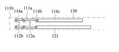
엔드 이펙터(110)는 제1축 규제 링크부(114)와, 제2축 규제 링크부(115)를 포함할 수 있다. 제1축 규제 링크부(114)는 제1축 구동 링크부(112)에 의해 제1,2 프레임(111a)(111b)이 제1축 방향으로 안정적으로 굽힘 동작하도록 규제한다. 제1축 규제 링크부(114)는 제1,2,3규제 링크(114a)(114b)(114c)를 구비한다. 제1규제 링크(114a)는 제2프레임(111b) 내에서 일단이 제1축 방향으로 회전 가능하게 지지된다. 제2규제 링크(114b)는 제1프레임(111a) 내에서 일단이 제1규제 링크(114a)의 타단과 제1축 방향으로 회전 가능하게 결합된다. 제3규제 링크(114c)는 하우징(130) 내에서 일단이 제2규제 링크(114b)의 타단과 제1축 방향으로 회전 가능하게 결합되고, 타단이 하우징(130) 내에서 이동 가능하게 지지된다.The
제2축 규제 링크부(115)는 제2축 구동 링크부(113)에 의해 제3,4 프레임(111c)(111d)이 제2축 방향으로 안정적으로 굽힘 동작하도록 규제한다. 제2축 규제 링크부(115)는 제4,5규제 링크(115a)(115b)를 구비한다. 제4규제 링크(115a)는 제4프레임(111d) 내에서 일단이 제2축 방향으로 회전 가능하게 지지된다. 제5규제 링크(115b)는 제3프레임(111c) 내에서 일단이 제4규제 링크(115a)의 타단과 제2축 방향으로 회전 가능하게 결합되고, 타단이 제2프레임(111b) 내에서 이동 가능하게 지지된다.The second shaft regulating
엔드 이펙터(110)는 1-자유도 파지 메커니즘을 가질 수 있다. 예를 들면, 엔드 이펙터(110)는 집게(116)를 포함한다. 집게(116)는 제4프레임(111d)의 말단에 장착된다. 집게(116)는 집게 작동부에 의해 서로 모아지거나 벌어지도록 적어도 하나가 회전 동작할 수 있다. 집게 작동부는 제4프레임(111d) 내에서 전술한 압전 구동기(140)(240)의 동력을 제공받아 2개의 죠(jaw)들 중 적어도 하나를 회전 운동시킬 수 있다. 집게 작동부는 압전 구동기(140)(240)에 의해 선형 운동하는 슬라이더와, 슬라이더의 선형 운동을 회전 운동으로 변환하여 2개의 죠들 중 적어도 하나를 회전시키는 링크부를 포함할 수 있다.The
엔드 이펙터(110)는 도 8에 도시된 바와 같이, 복수 개로 구비될 수 있다. 엔드 이펙터(110)들은 전술한 압전 구동기(140)(240)와 동력 전달부(120)에 의해 서로 독립적으로 운동할 수 있다. 여기서, 엔드 이펙터(110)들은 하우징(130)들에 하나씩 나뉘어 연결될 수 있다. 하우징(130)마다 압전 구동기(140)(240)와 동력 전달부(120)를 수용하여 하우징(130)에 연결된 엔드 이펙터(110)를 운동시킬 수 있다. 전술한 것처럼, 수술 도구는 다관절로 구성될 경우, 관절 별로 독립적인 운동 제어가 가능하다. 관절수가 증가하더라도 다른 관절에 영향을 주지 않게 되므로, 다관절 구조로 확장이 용이해질 수 있다.The
도 9를 참조하면, 동력 전달부(320)는 회전 동작함에 따라 엔드 이펙터에 동력을 전달하는 로터(321)를 포함할 수 있다. 이 경우, 압전 구동기(340)는 로터(321)를 회전 동작시키도록 하우징(130) 내에 장착된다.Referring to FIG. 9, the
일 예로, 압전 구동기(340)는 도 10에 도시된 바와 같이, 하우징(130) 내에서 로터(321)의 일단부에 대응되게 환형으로 배열되어 지지되는 복수의 압전 소자(341)들과, 압전 소자(341)들에서 로터(321)의 일단부를 향한 면에 형성된 푸셔(342)들을 포함할 수 있다. 인접한 압전 소자(341)들 간에 서로 반대되는 변위가 발생하도록 전압을 인가하면, 푸셔(342)들에 진동이 발생하게 된다. 이때, 푸셔(342)들의 진동 방향은 압전 소자(341)들에 인가되는 전압 방향에 따라 로터(321)를 정회전 또는 역회전시키도록 설정될 수 있다. 따라서, 압전 소자(341)들에 인가되는 전압 방향을 제어함에 따라, 로터(321)를 정방향 또는 역방향으로 회전시킬 수 있다.10, the
로터(321)는 둘레에 축 길이 방향으로 서로 이격된 복수의 날개(322)들을 포함할 수 있다. 이 경우, 압전 구동기(340)는 날개(322)들에 각각 대응되게 하우징(130) 내에 장착된다. 따라서, 로터(321)에 제공되는 동력이 증가되어 로터(321)는 보다 원활히 회전 동작할 수 있다.The
여기서, 동력 전달부(320)가 엔드 이펙터에 독립된 회전 동력들을 전달하도록 복수의 로터(321)들을 포함할 수 있다. 로터(321)들은 병렬로 회전 동작함에 따라 엔드 이펙터에 동력을 각각 전달한다. 이 경우, 압전 구동기(340)는 로터(321)들의 각 둘레에 배치되도록 하우징(130) 내에 장착되어 로터(321)들을 독립적으로 회전 동작시킨다. 로터(321)들은 중공을 가지며 동축 상으로 삽입되어 배열될 수 있다.Here, the
도 9 및 도 10의 로터(321)와 압전 구동기(340)를 이용하면, 엔드 이펙터는 2-자유도 회전 매커니즘을 갖도록 구성할 수 있다. 예를 들어, 엔드 이펙터는 프레임과, 집게를 포함한다. 프레임은 하우징(130)에 로터(321)의 회전 방향과 동일한 방향으로 회전 가능하게 결합된다. 그리고, 프레임은 로터(321)들 중 하나와 연결되어 회전할 수 있다. 집게는 프레임의 말단에 로터(321)의 회전 방향과 회전 가능하게 결합된다. 집게는 로터(321)들 중 다른 하나와 연결되어 회전할 수 있다. 집게는 전술한 예와 같이, 1-자유도 파지 메커니즘을 갖도록 구성될 수 있다.By using the
110..엔드 이펙터120,320..동력 전달부
121..슬라이더130..하우징
140,240,340..압전 구동기321..로터110 ..
121 ..
140,240,340 ..
Claims (13)
Translated fromKorean상기 엔드 이펙터가 운동할 수 있도록 상기 엔드 이펙터에 동력을 전달하는 동력 전달부;
상기 동력 전달부를 감싸는 하우징; 및
상기 하우징 내에 수용되어 상기 동력 전달부에 동력을 제공하는 압전 구동기를 포함하며,
상기 동력 전달부는 선형 동작함에 따라 상기 엔드 이펙터에 동력을 전달하는 슬라이더를 포함하며;
상기 압전 구동기는 상기 슬라이더의 둘레에 배치되도록 상기 하우징 내에 장착되어 상기 슬라이더를 선형 동작시키는 수술 도구.An end effector for performing a surgical operation on a surgical site;
A power transmission unit for transmitting power to the end effector so that the end effector can move;
A housing surrounding the power transmission unit; And
And a piezoelectric actuator accommodated in the housing to provide power to the power transmitting portion,
The power transmission portion includes a slider that transmits power to the end effector as it is operated linearly;
Wherein the piezoelectric actuator is mounted in the housing so as to be disposed around the slider, and linearly operates the slider.
상기 압전 구동기는,
상기 하우징의 내벽에 고정된 서포터;
상기 서포터 상에 서로 이격되어 배치된 한 쌍의 압전 소자들; 및
상기 압전 소자들에 각각 고정되고 서로 이격되어 배치된 한 쌍의 탄성체들과, 상기 탄성체들을 상기 서포터에 각각 고정시키는 고정 돌기들, 및 상기 탄성체들을 연결하고 상기 슬라이더에 접촉되는 커플링 팁을 구비하는 탄력부를 포함하는 수술 도구.3. The method of claim 2,
The piezoelectric actuator includes:
A supporter fixed to an inner wall of the housing;
A pair of piezoelectric elements spaced apart from each other on the supporter; And
A pair of elastic bodies fixed to the piezoelectric elements and spaced apart from each other, fixing protrusions each fixing the elastic bodies to the supporter, and coupling tips connecting the elastic bodies and contacting the slider A surgical tool comprising a resilient portion.
상기 동력 전달부는 상기 슬라이더를 복수 개로 포함하여 병렬로 선형 동작함에 따라 상기 엔드 이펙터에 각각 동력을 전달하며;
상기 압전 구동기는 상기 슬라이더들의 각 둘레에 배치되도록 상기 하우징 내에 장착되어 상기 슬라이더들을 독립적으로 선형 동작시키는 수술 도구.3. The method of claim 2,
Wherein the power transmission unit transmits power to the end effector in a linear operation including a plurality of the sliders in parallel;
Wherein the piezoelectric actuator is mounted in the housing to be disposed around each of the sliders so as to independently operate the sliders in a linear manner.
상기 엔드 이펙터는,
상기 하우징에 제1축 방향으로 회전 가능하게 관절로 결합된 제1프레임과, 상기 제1프레임에 제1축 방향으로 회전 가능하게 관절로 결합된 제2프레임과, 상기 제2프레임에 제1축 방향과 수직한 제2축 방향으로 회전 가능하게 관절로 결합된 제3프레임, 및 상기 제3프레임에 제2축 방향으로 회전 가능하게 관절로 결합된 제4프레임을 구비한 프레임부;
상기 하우징 내에서 일단이 상기 슬라이더들 중 어느 하나와 제1축 방향으로 회전 가능하게 결합된 제1구동 링크와, 상기 제1프레임 내에서 일단이 상기 제1구동 링크의 타단과 제1축 방향으로 회전 가능하게 결합되고 타단이 상기 제2프레임 내에 회전 가능하게 지지되는 제2구동 링크를 구비한 제1축 구동 링크부; 및
상기 하우징 내에서 일단이 상기 슬라이더들 중 다른 하나와 제1축 방향으로 회전 가능하게 결합된 제3구동 링크와, 상기 제1프레임 내에서 일단이 상기 제3구동 링크의 타단과 제1축 방향으로 회전 가능하게 결합되는 제4구동 링크와, 상기 제2프레임 내에서 상기 제4구동 링크의 타단과 제1축 방향으로 회전 가능하게 결합된 2-축 관절과, 상기 제2프레임 내에서 일단이 상기 2-축 관절과 제2축 방향으로 회전 가능하게 결합된 제5구동 링크, 및 상기 제3프레임 내에서 일단이 상기 제5구동 링크의 타단과 제2축 방향으로 회전 가능하게 결합되고 타단이 상기 제4프레임 내에 회전 가능하게 지지된 제6 구동링크를 구비한 제2축 구동 링크부를 포함하는 수술 도구.5. The method of claim 4,
The end-
A first frame coupled to the housing rotatably in a first axis direction, a second frame coupled to the first frame so as to be rotatable in a first axis direction, And a fourth frame rotatably jointed to the third frame rotatably in a second axial direction; and a second frame that is rotatably connected to the third frame in a second axial direction perpendicular to the first frame;
A first driving link having one end rotatably coupled to one of the sliders in a first axis direction in the housing, and a second driving link having one end in the first frame and a second driving link, A first shaft driving link portion having a second driving link rotatably coupled and the other end rotatably supported in the second frame; And
A third drive link having one end rotatably coupled to the other one of the sliders in a first axis direction in the housing, and a third drive link having one end in the first frame and a second end in the first axis direction A first driving link rotatably coupled to the first driving link and a second driving link rotatably coupled to the second driving link in the second frame so as to be rotatable in the first axis direction with the other end of the fourth driving link, A fifth drive link rotatably coupled to the 2-axis joint in the second axis direction, and a fifth drive link rotatably coupled to the other end of the fifth drive link in the second axis within the third frame, And a second axial drive link portion having a sixth drive link rotatably supported within the fourth frame.
상기 엔드 이펙터는,
상기 제2프레임 내에서 일단이 제1축 방향으로 회전 가능하게 지지된 제1규제 링크와, 상기 제1프레임 내에서 일단이 상기 제1규제 링크의 타단과 제1축 방향으로 회전 가능하게 결합된 제2규제 링크, 및 상기 하우징 내에서 일단이 상기 제2규제 링크의 타단과 제1축 방향으로 회전 가능하게 결합되고 타단이 상기 하우징 내에서 이동 가능하게 지지되는 제3규제 링크를 구비한 제1축 규제 링크부; 및
상기 제4프레임 내에서 일단이 제2축 방향으로 회전 가능하게 지지된 제4규제 링크, 및 상기 제3프레임 내에서 일단이 상기 제4규제 링크의 타단과 제2축 방향으로 회전 가능하게 결합되고 타단이 제2 프레임 내에서 이동 가능하게 지지된 제5규제 링크를 구비한 제2축 규제 링크부를 더 포함하는 수술 도구.8. The method of claim 7,
The end-
A first regulating link having one end rotatably supported in the first frame in the second frame and a second regulating link having one end rotatably coupled to the other end of the first regulating link in the first axis direction And a third regulating link having one end in the housing rotatably coupled with the other end of the second regulating link in the first axial direction and the other end being movably supported in the housing, Axis regulating link portion; And
A fourth regulating link whose one end is rotatably supported in a second axial direction in the fourth frame and a fourth regulating link whose one end is rotatably engaged with the other end of the fourth regulating link in a second axial direction in the third frame And a second shaft regulating link portion having a fifth regulating link whose other end is movably supported within the second frame.
상기 엔드 이펙터는 복수 개로 구비되며, 상기 압전 구동기와 상기 동력 전달부에 의해 서로 독립적으로 운동 가능하게 된 수술 도구.9. The method of claim 8,
Wherein the end effector includes a plurality of end effectors, and the end effector is independently movable by the piezoelectric actuator and the power transmitting portion.
Priority Applications (2)
| Application Number | Priority Date | Filing Date | Title |
|---|---|---|---|
| KR1020100122947AKR101731969B1 (en) | 2010-12-03 | 2010-12-03 | Surgical instrument |
| US13/219,168US9622764B2 (en) | 2010-12-03 | 2011-08-26 | Surgical instrument |
Applications Claiming Priority (1)
| Application Number | Priority Date | Filing Date | Title |
|---|---|---|---|
| KR1020100122947AKR101731969B1 (en) | 2010-12-03 | 2010-12-03 | Surgical instrument |
Related Child Applications (1)
| Application Number | Title | Priority Date | Filing Date |
|---|---|---|---|
| KR1020170010546ADivisionKR101808279B1 (en) | 2017-01-23 | 2017-01-23 | Surgical instrument |
Publications (2)
| Publication Number | Publication Date |
|---|---|
| KR20120061594A KR20120061594A (en) | 2012-06-13 |
| KR101731969B1true KR101731969B1 (en) | 2017-05-02 |
Family
ID=46162909
Family Applications (1)
| Application Number | Title | Priority Date | Filing Date |
|---|---|---|---|
| KR1020100122947AExpired - Fee RelatedKR101731969B1 (en) | 2010-12-03 | 2010-12-03 | Surgical instrument |
Country Status (2)
| Country | Link |
|---|---|
| US (1) | US9622764B2 (en) |
| KR (1) | KR101731969B1 (en) |
Families Citing this family (9)
| Publication number | Priority date | Publication date | Assignee | Title |
|---|---|---|---|---|
| KR101418718B1 (en)* | 2012-12-26 | 2014-07-14 | (주)미래컴퍼니 | Structure of instrument coupler of surgical robot arm |
| KR101455510B1 (en)* | 2013-02-08 | 2014-10-27 | 정창욱 | Instrument for Minimally Invasive Surgery Having Link-type Articulation Unit |
| CN105538288B (en)* | 2014-10-22 | 2020-08-28 | 精工爱普生株式会社 | robot |
| KR101643362B1 (en) | 2014-12-26 | 2016-07-27 | 한국과학기술원 | A surgical device |
| US9888975B2 (en)* | 2015-12-04 | 2018-02-13 | Ethicon Endo-Surgery, Llc | Methods, systems, and devices for control of surgical tools in a robotic surgical system |
| BR112018009251A2 (en) | 2016-02-05 | 2019-04-09 | Board Of Regents Of The University Of Texas System | surgical apparatus and customized main controller for a surgical apparatus |
| KR102708262B1 (en) | 2016-02-05 | 2024-09-20 | 보드 오브 리전츠, 더 유니버시티 오브 텍사스 시스템 | The manipulatable intraruminal medical device |
| CN106264665B (en)* | 2016-07-28 | 2018-10-16 | 清华大学 | A kind of flexible operation device |
| CN109124555B (en)* | 2018-07-09 | 2020-11-17 | 南京航空航天大学 | Straight line-swing three-degree-of-freedom magnetic attraction type laparoscope mechanism |
Citations (2)
| Publication number | Priority date | Publication date | Assignee | Title |
|---|---|---|---|---|
| KR100778387B1 (en) | 2006-12-26 | 2007-11-28 | 한국과학기술원 | Laparoscopic Surgery Robot with Multiple Degrees of Freedom and Its Force Measuring Method |
| JP2010535089A (en) | 2007-07-31 | 2010-11-18 | エシコン・エンド−サージェリィ・インコーポレイテッド | Ultrasonic surgical instrument |
Family Cites Families (11)
| Publication number | Priority date | Publication date | Assignee | Title |
|---|---|---|---|---|
| JPH05123325A (en) | 1991-11-01 | 1993-05-21 | Olympus Optical Co Ltd | Treating tool |
| JPH0889509A (en) | 1994-09-28 | 1996-04-09 | Hiroaki Nomori | End tractor and its introducing forceps and needle clamper |
| US5792135A (en) | 1996-05-20 | 1998-08-11 | Intuitive Surgical, Inc. | Articulated surgical instrument for performing minimally invasive surgery with enhanced dexterity and sensitivity |
| AU2003257309A1 (en) | 2002-08-13 | 2004-02-25 | Microbotics Corporation | Microsurgical robot system |
| US7125727B2 (en)* | 2003-01-29 | 2006-10-24 | Protedyne Corporation | Sample handling tool with piezoelectric actuator |
| US7390294B2 (en)* | 2004-05-28 | 2008-06-24 | Ethicon Endo-Surgery, Inc. | Piezo electrically driven bellows infuser for hydraulically controlling an adjustable gastric band |
| KR20100090528A (en) | 2009-02-06 | 2010-08-16 | 삼성전자주식회사 | Piezoelectric ultrasonic motor and method for fabricating the same |
| US9844414B2 (en)* | 2009-08-31 | 2017-12-19 | Gregory S. Fischer | System and method for robotic surgical intervention in a magnetic resonance imager |
| CN103052368B (en)* | 2010-07-20 | 2016-01-20 | 约翰霍普金斯大学 | surface tracking and motion compensation surgical tool system |
| US8891924B2 (en)* | 2012-04-26 | 2014-11-18 | Bio-Medical Engineering (HK) Limited | Magnetic-anchored robotic system |
| US10179033B2 (en)* | 2012-04-26 | 2019-01-15 | Bio-Medical Engineering (HK) Limited | Magnetic-anchored robotic system |
- 2010
- 2010-12-03KRKR1020100122947Apatent/KR101731969B1/ennot_activeExpired - Fee Related
- 2011
- 2011-08-26USUS13/219,168patent/US9622764B2/enactiveActive
Patent Citations (2)
| Publication number | Priority date | Publication date | Assignee | Title |
|---|---|---|---|---|
| KR100778387B1 (en) | 2006-12-26 | 2007-11-28 | 한국과학기술원 | Laparoscopic Surgery Robot with Multiple Degrees of Freedom and Its Force Measuring Method |
| JP2010535089A (en) | 2007-07-31 | 2010-11-18 | エシコン・エンド−サージェリィ・インコーポレイテッド | Ultrasonic surgical instrument |
Also Published As
| Publication number | Publication date |
|---|---|
| KR20120061594A (en) | 2012-06-13 |
| US20120143174A1 (en) | 2012-06-07 |
| US9622764B2 (en) | 2017-04-18 |
Similar Documents
| Publication | Publication Date | Title |
|---|---|---|
| KR101731969B1 (en) | Surgical instrument | |
| CN112842534B (en) | Surgical tool system | |
| EP3634295B1 (en) | Instrument interface for robotic surgical instrument | |
| KR102330042B1 (en) | medical instrument with tension band | |
| KR101173619B1 (en) | Robot apparatus for endoscopic surgery | |
| EP3329876B1 (en) | Manipulator | |
| WO2005055840A1 (en) | Manipulator with multiple degrees of freedom | |
| JP6653044B2 (en) | Surgical instruments and systems | |
| WO2017037532A1 (en) | Surgical instrument with increased actuation force | |
| CN107320183B (en) | Surgical instrument for minimally invasive surgery robot and minimally invasive surgery robot | |
| WO2022222287A1 (en) | Dexterous operation arm driven by modular joint time-sharing switching | |
| WO2020084360A1 (en) | Surgical tools with opposing translating gears | |
| Sallé et al. | Surgery grippers for minimally invasive heart surgery | |
| KR101808279B1 (en) | Surgical instrument | |
| Catherine et al. | Comparative review of endoscopic devices articulations technologies developed for minimally invasive medical procedures | |
| JP2004283925A (en) | Manipulator with hand arm mechanism | |
| Gao et al. | A miniature 3-dof flexible parallel robotic wrist using niti wires for gastrointestinal endoscopic surgery | |
| CN115414092A (en) | A wire-driven motion module and minimally invasive surgical forceps | |
| CN115363647A (en) | Driving force transmission device of surgical instrument and surgical instrument comprising same | |
| WO2010117051A1 (en) | Manipulator | |
| CN114948217A (en) | Multi-degree-of-freedom surgical actuator for minimally invasive surgery | |
| WO2015182561A1 (en) | Manipulator | |
| Zhang et al. | Design and kinematic modeling of a concentric torsionally-steerable flexible surgical robot | |
| CN116269803B (en) | Surgical instrument and surgical robot | |
| KR101502581B1 (en) | Surgical operation by wire type surgical operation apparatus |
Legal Events
| Date | Code | Title | Description |
|---|---|---|---|
| PA0109 | Patent application | St.27 status event code:A-0-1-A10-A12-nap-PA0109 | |
| PG1501 | Laying open of application | St.27 status event code:A-1-1-Q10-Q12-nap-PG1501 | |
| R18-X000 | Changes to party contact information recorded | St.27 status event code:A-3-3-R10-R18-oth-X000 | |
| A201 | Request for examination | ||
| PA0201 | Request for examination | St.27 status event code:A-1-2-D10-D11-exm-PA0201 | |
| P22-X000 | Classification modified | St.27 status event code:A-2-2-P10-P22-nap-X000 | |
| P22-X000 | Classification modified | St.27 status event code:A-2-2-P10-P22-nap-X000 | |
| D13-X000 | Search requested | St.27 status event code:A-1-2-D10-D13-srh-X000 | |
| D14-X000 | Search report completed | St.27 status event code:A-1-2-D10-D14-srh-X000 | |
| E902 | Notification of reason for refusal | ||
| PE0902 | Notice of grounds for rejection | St.27 status event code:A-1-2-D10-D21-exm-PE0902 | |
| A107 | Divisional application of patent | ||
| E13-X000 | Pre-grant limitation requested | St.27 status event code:A-2-3-E10-E13-lim-X000 | |
| P11-X000 | Amendment of application requested | St.27 status event code:A-2-2-P10-P11-nap-X000 | |
| P13-X000 | Application amended | St.27 status event code:A-2-2-P10-P13-nap-X000 | |
| PA0107 | Divisional application | St.27 status event code:A-0-1-A10-A18-div-PA0107 St.27 status event code:A-0-1-A10-A16-div-PA0107 | |
| E701 | Decision to grant or registration of patent right | ||
| PE0701 | Decision of registration | St.27 status event code:A-1-2-D10-D22-exm-PE0701 | |
| GRNT | Written decision to grant | ||
| PR0701 | Registration of establishment | St.27 status event code:A-2-4-F10-F11-exm-PR0701 | |
| PR1002 | Payment of registration fee | St.27 status event code:A-2-2-U10-U11-oth-PR1002 Fee payment year number:1 | |
| PG1601 | Publication of registration | St.27 status event code:A-4-4-Q10-Q13-nap-PG1601 | |
| PR1001 | Payment of annual fee | St.27 status event code:A-4-4-U10-U11-oth-PR1001 Fee payment year number:4 | |
| PR1001 | Payment of annual fee | St.27 status event code:A-4-4-U10-U11-oth-PR1001 Fee payment year number:5 | |
| PR1001 | Payment of annual fee | St.27 status event code:A-4-4-U10-U11-oth-PR1001 Fee payment year number:6 | |
| PR1001 | Payment of annual fee | St.27 status event code:A-4-4-U10-U11-oth-PR1001 Fee payment year number:7 | |
| PC1903 | Unpaid annual fee | St.27 status event code:A-4-4-U10-U13-oth-PC1903 Not in force date:20240426 Payment event data comment text:Termination Category : DEFAULT_OF_REGISTRATION_FEE | |
| P22-X000 | Classification modified | St.27 status event code:A-4-4-P10-P22-nap-X000 | |
| PC1903 | Unpaid annual fee | St.27 status event code:N-4-6-H10-H13-oth-PC1903 Ip right cessation event data comment text:Termination Category : DEFAULT_OF_REGISTRATION_FEE Not in force date:20240426 |