KR101731566B1 - High definition heater system having a fluid medium - Google Patents
High definition heater system having a fluid mediumDownload PDFInfo
- Publication number
- KR101731566B1 KR101731566B1KR1020147008066AKR20147008066AKR101731566B1KR 101731566 B1KR101731566 B1KR 101731566B1KR 1020147008066 AKR1020147008066 AKR 1020147008066AKR 20147008066 AKR20147008066 AKR 20147008066AKR 101731566 B1KR101731566 B1KR 101731566B1
- Authority
- KR
- South Korea
- Prior art keywords
- delete delete
- heater
- tuning layer
- tuning
- layer
- Prior art date
- Legal status (The legal status is an assumption and is not a legal conclusion. Google has not performed a legal analysis and makes no representation as to the accuracy of the status listed.)
- Active
Links
- 239000012530fluidSubstances0.000titleclaimsabstractdescription41
- 238000010438heat treatmentMethods0.000claimsabstractdescription34
- 238000001816coolingMethods0.000claimsabstractdescription13
- 238000000034methodMethods0.000claimsdescription26
- 239000000758substrateSubstances0.000claimsdescription21
- 239000000463materialSubstances0.000claimsdescription18
- 238000009826distributionMethods0.000claimsdescription6
- 239000007788liquidSubstances0.000claimsdescription3
- 238000012546transferMethods0.000claimsdescription3
- 239000002826coolantSubstances0.000claimsdescription2
- NJPPVKZQTLUDBO-UHFFFAOYSA-NnovaluronChemical compoundC1=C(Cl)C(OC(F)(F)C(OC(F)(F)F)F)=CC=C1NC(=O)NC(=O)C1=C(F)C=CC=C1FNJPPVKZQTLUDBO-UHFFFAOYSA-N0.000claimsdescription2
- 239000010410layerSubstances0.000description96
- 239000004065semiconductorSubstances0.000description12
- 238000012545processingMethods0.000description9
- 238000004891communicationMethods0.000description4
- 239000013464silicone adhesiveSubstances0.000description4
- RYGMFSIKBFXOCR-UHFFFAOYSA-NCopperChemical compound[Cu]RYGMFSIKBFXOCR-UHFFFAOYSA-N0.000description3
- 239000004642PolyimideSubstances0.000description3
- 239000012790adhesive layerSubstances0.000description3
- XAGFODPZIPBFFR-UHFFFAOYSA-NaluminiumChemical compound[Al]XAGFODPZIPBFFR-UHFFFAOYSA-N0.000description3
- 229910052782aluminiumInorganic materials0.000description3
- 229910052802copperInorganic materials0.000description3
- 239000010949copperSubstances0.000description3
- 229920001721polyimidePolymers0.000description3
- OKTJSMMVPCPJKN-UHFFFAOYSA-NCarbonChemical compound[C]OKTJSMMVPCPJKN-UHFFFAOYSA-N0.000description2
- PXHVJJICTQNCMI-UHFFFAOYSA-NNickelChemical compound[Ni]PXHVJJICTQNCMI-UHFFFAOYSA-N0.000description2
- 239000010408filmSubstances0.000description2
- 230000004907fluxEffects0.000description2
- 239000011888foilSubstances0.000description2
- 239000007789gasSubstances0.000description2
- 229910002804graphiteInorganic materials0.000description2
- 239000010439graphiteSubstances0.000description2
- 239000002346layers by functionSubstances0.000description2
- 238000004519manufacturing processMethods0.000description2
- 238000012986modificationMethods0.000description2
- 230000004048modificationEffects0.000description2
- 229910000640Fe alloyInorganic materials0.000description1
- 239000004820Pressure-sensitive adhesiveSubstances0.000description1
- XUIMIQQOPSSXEZ-UHFFFAOYSA-NSiliconChemical compound[Si]XUIMIQQOPSSXEZ-UHFFFAOYSA-N0.000description1
- 238000009825accumulationMethods0.000description1
- 239000000853adhesiveSubstances0.000description1
- 230000001070adhesive effectEffects0.000description1
- 230000000712assemblyEffects0.000description1
- 238000000429assemblyMethods0.000description1
- 238000010276constructionMethods0.000description1
- 239000000112cooling gasSubstances0.000description1
- 238000012937correctionMethods0.000description1
- 230000007423decreaseEffects0.000description1
- 230000001419dependent effectEffects0.000description1
- 230000008021depositionEffects0.000description1
- 238000013461designMethods0.000description1
- 230000009977dual effectEffects0.000description1
- 238000005516engineering processMethods0.000description1
- 238000005530etchingMethods0.000description1
- 229910001026inconelInorganic materials0.000description1
- UGKDIUIOSMUOAW-UHFFFAOYSA-Niron nickelChemical compound[Fe].[Ni]UGKDIUIOSMUOAW-UHFFFAOYSA-N0.000description1
- 238000012423maintenanceMethods0.000description1
- 238000005259measurementMethods0.000description1
- 239000000203mixtureSubstances0.000description1
- 229910052759nickelInorganic materials0.000description1
- 230000003287optical effectEffects0.000description1
- TWNQGVIAIRXVLR-UHFFFAOYSA-Noxo(oxoalumanyloxy)alumaneChemical compoundO=[Al]O[Al]=OTWNQGVIAIRXVLR-UHFFFAOYSA-N0.000description1
- 230000002093peripheral effectEffects0.000description1
- 238000003825pressingMethods0.000description1
- 239000003507refrigerantSubstances0.000description1
- 238000007789sealingMethods0.000description1
- 230000035945sensitivityEffects0.000description1
- 230000035939shockEffects0.000description1
- 229910052710siliconInorganic materials0.000description1
- 239000010703siliconSubstances0.000description1
- 238000003980solgel methodMethods0.000description1
- 239000007787solidSubstances0.000description1
- 230000000153supplemental effectEffects0.000description1
- 230000008542thermal sensitivityEffects0.000description1
- 238000007751thermal sprayingMethods0.000description1
- 239000010409thin filmSubstances0.000description1
- 238000012876topographyMethods0.000description1
- 239000011800void materialSubstances0.000description1
Images


Classifications
- H—ELECTRICITY
- H01—ELECTRIC ELEMENTS
- H01L—SEMICONDUCTOR DEVICES NOT COVERED BY CLASS H10
- H01L21/00—Processes or apparatus adapted for the manufacture or treatment of semiconductor or solid state devices or of parts thereof
- H01L21/67—Apparatus specially adapted for handling semiconductor or electric solid state devices during manufacture or treatment thereof; Apparatus specially adapted for handling wafers during manufacture or treatment of semiconductor or electric solid state devices or components ; Apparatus not specifically provided for elsewhere
- H01L21/67005—Apparatus not specifically provided for elsewhere
- H01L21/67011—Apparatus for manufacture or treatment
- H01L21/67098—Apparatus for thermal treatment
- H01L21/67103—Apparatus for thermal treatment mainly by conduction
- H—ELECTRICITY
- H01—ELECTRIC ELEMENTS
- H01L—SEMICONDUCTOR DEVICES NOT COVERED BY CLASS H10
- H01L21/00—Processes or apparatus adapted for the manufacture or treatment of semiconductor or solid state devices or of parts thereof
- H01L21/67—Apparatus specially adapted for handling semiconductor or electric solid state devices during manufacture or treatment thereof; Apparatus specially adapted for handling wafers during manufacture or treatment of semiconductor or electric solid state devices or components ; Apparatus not specifically provided for elsewhere
- H01L21/67005—Apparatus not specifically provided for elsewhere
- H01L21/67011—Apparatus for manufacture or treatment
- H01L21/67098—Apparatus for thermal treatment
- H01L21/67109—Apparatus for thermal treatment mainly by convection
- H—ELECTRICITY
- H01—ELECTRIC ELEMENTS
- H01L—SEMICONDUCTOR DEVICES NOT COVERED BY CLASS H10
- H01L21/00—Processes or apparatus adapted for the manufacture or treatment of semiconductor or solid state devices or of parts thereof
- H01L21/67—Apparatus specially adapted for handling semiconductor or electric solid state devices during manufacture or treatment thereof; Apparatus specially adapted for handling wafers during manufacture or treatment of semiconductor or electric solid state devices or components ; Apparatus not specifically provided for elsewhere
- H01L21/67005—Apparatus not specifically provided for elsewhere
- H01L21/67242—Apparatus for monitoring, sorting or marking
- H01L21/67248—Temperature monitoring
- H—ELECTRICITY
- H01—ELECTRIC ELEMENTS
- H01L—SEMICONDUCTOR DEVICES NOT COVERED BY CLASS H10
- H01L21/00—Processes or apparatus adapted for the manufacture or treatment of semiconductor or solid state devices or of parts thereof
- H01L21/67—Apparatus specially adapted for handling semiconductor or electric solid state devices during manufacture or treatment thereof; Apparatus specially adapted for handling wafers during manufacture or treatment of semiconductor or electric solid state devices or components ; Apparatus not specifically provided for elsewhere
- H01L21/683—Apparatus specially adapted for handling semiconductor or electric solid state devices during manufacture or treatment thereof; Apparatus specially adapted for handling wafers during manufacture or treatment of semiconductor or electric solid state devices or components ; Apparatus not specifically provided for elsewhere for supporting or gripping
- H01L21/6831—Apparatus specially adapted for handling semiconductor or electric solid state devices during manufacture or treatment thereof; Apparatus specially adapted for handling wafers during manufacture or treatment of semiconductor or electric solid state devices or components ; Apparatus not specifically provided for elsewhere for supporting or gripping using electrostatic chucks
- H01L21/6833—Details of electrostatic chucks
- H—ELECTRICITY
- H01—ELECTRIC ELEMENTS
- H01L—SEMICONDUCTOR DEVICES NOT COVERED BY CLASS H10
- H01L21/00—Processes or apparatus adapted for the manufacture or treatment of semiconductor or solid state devices or of parts thereof
- H01L21/67—Apparatus specially adapted for handling semiconductor or electric solid state devices during manufacture or treatment thereof; Apparatus specially adapted for handling wafers during manufacture or treatment of semiconductor or electric solid state devices or components ; Apparatus not specifically provided for elsewhere
- H01L21/683—Apparatus specially adapted for handling semiconductor or electric solid state devices during manufacture or treatment thereof; Apparatus specially adapted for handling wafers during manufacture or treatment of semiconductor or electric solid state devices or components ; Apparatus not specifically provided for elsewhere for supporting or gripping
- H01L21/6835—Apparatus specially adapted for handling semiconductor or electric solid state devices during manufacture or treatment thereof; Apparatus specially adapted for handling wafers during manufacture or treatment of semiconductor or electric solid state devices or components ; Apparatus not specifically provided for elsewhere for supporting or gripping using temporarily an auxiliary support
- H—ELECTRICITY
- H05—ELECTRIC TECHNIQUES NOT OTHERWISE PROVIDED FOR
- H05B—ELECTRIC HEATING; ELECTRIC LIGHT SOURCES NOT OTHERWISE PROVIDED FOR; CIRCUIT ARRANGEMENTS FOR ELECTRIC LIGHT SOURCES, IN GENERAL
- H05B1/00—Details of electric heating devices
- H—ELECTRICITY
- H05—ELECTRIC TECHNIQUES NOT OTHERWISE PROVIDED FOR
- H05B—ELECTRIC HEATING; ELECTRIC LIGHT SOURCES NOT OTHERWISE PROVIDED FOR; CIRCUIT ARRANGEMENTS FOR ELECTRIC LIGHT SOURCES, IN GENERAL
- H05B1/00—Details of electric heating devices
- H05B1/02—Automatic switching arrangements specially adapted to apparatus ; Control of heating devices
- H05B1/0202—Switches
- H—ELECTRICITY
- H05—ELECTRIC TECHNIQUES NOT OTHERWISE PROVIDED FOR
- H05B—ELECTRIC HEATING; ELECTRIC LIGHT SOURCES NOT OTHERWISE PROVIDED FOR; CIRCUIT ARRANGEMENTS FOR ELECTRIC LIGHT SOURCES, IN GENERAL
- H05B1/00—Details of electric heating devices
- H05B1/02—Automatic switching arrangements specially adapted to apparatus ; Control of heating devices
- H05B1/0227—Applications
- H05B1/023—Industrial applications
- H05B1/0233—Industrial applications for semiconductors manufacturing
- H—ELECTRICITY
- H05—ELECTRIC TECHNIQUES NOT OTHERWISE PROVIDED FOR
- H05B—ELECTRIC HEATING; ELECTRIC LIGHT SOURCES NOT OTHERWISE PROVIDED FOR; CIRCUIT ARRANGEMENTS FOR ELECTRIC LIGHT SOURCES, IN GENERAL
- H05B3/00—Ohmic-resistance heating
- H05B3/02—Details
- H—ELECTRICITY
- H05—ELECTRIC TECHNIQUES NOT OTHERWISE PROVIDED FOR
- H05B—ELECTRIC HEATING; ELECTRIC LIGHT SOURCES NOT OTHERWISE PROVIDED FOR; CIRCUIT ARRANGEMENTS FOR ELECTRIC LIGHT SOURCES, IN GENERAL
- H05B3/00—Ohmic-resistance heating
- H05B3/02—Details
- H05B3/06—Heater elements structurally combined with coupling elements or holders
- H—ELECTRICITY
- H05—ELECTRIC TECHNIQUES NOT OTHERWISE PROVIDED FOR
- H05B—ELECTRIC HEATING; ELECTRIC LIGHT SOURCES NOT OTHERWISE PROVIDED FOR; CIRCUIT ARRANGEMENTS FOR ELECTRIC LIGHT SOURCES, IN GENERAL
- H05B3/00—Ohmic-resistance heating
- H05B3/20—Heating elements having extended surface area substantially in a two-dimensional plane, e.g. plate-heater
- H—ELECTRICITY
- H05—ELECTRIC TECHNIQUES NOT OTHERWISE PROVIDED FOR
- H05B—ELECTRIC HEATING; ELECTRIC LIGHT SOURCES NOT OTHERWISE PROVIDED FOR; CIRCUIT ARRANGEMENTS FOR ELECTRIC LIGHT SOURCES, IN GENERAL
- H05B2203/00—Aspects relating to Ohmic resistive heating covered by group H05B3/00
- H05B2203/002—Heaters using a particular layout for the resistive material or resistive elements
- H05B2203/005—Heaters using a particular layout for the resistive material or resistive elements using multiple resistive elements or resistive zones isolated from each other
- H—ELECTRICITY
- H05—ELECTRIC TECHNIQUES NOT OTHERWISE PROVIDED FOR
- H05B—ELECTRIC HEATING; ELECTRIC LIGHT SOURCES NOT OTHERWISE PROVIDED FOR; CIRCUIT ARRANGEMENTS FOR ELECTRIC LIGHT SOURCES, IN GENERAL
- H05B2203/00—Aspects relating to Ohmic resistive heating covered by group H05B3/00
- H05B2203/013—Heaters using resistive films or coatings
- H—ELECTRICITY
- H05—ELECTRIC TECHNIQUES NOT OTHERWISE PROVIDED FOR
- H05B—ELECTRIC HEATING; ELECTRIC LIGHT SOURCES NOT OTHERWISE PROVIDED FOR; CIRCUIT ARRANGEMENTS FOR ELECTRIC LIGHT SOURCES, IN GENERAL
- H05B2213/00—Aspects relating both to resistive heating and to induction heating, covered by H05B3/00 and H05B6/00
- H05B2213/03—Heating plates made out of a matrix of heating elements that can define heating areas adapted to cookware randomly placed on the heating plate
- Y—GENERAL TAGGING OF NEW TECHNOLOGICAL DEVELOPMENTS; GENERAL TAGGING OF CROSS-SECTIONAL TECHNOLOGIES SPANNING OVER SEVERAL SECTIONS OF THE IPC; TECHNICAL SUBJECTS COVERED BY FORMER USPC CROSS-REFERENCE ART COLLECTIONS [XRACs] AND DIGESTS
- Y10—TECHNICAL SUBJECTS COVERED BY FORMER USPC
- Y10T—TECHNICAL SUBJECTS COVERED BY FORMER US CLASSIFICATION
- Y10T156/00—Adhesive bonding and miscellaneous chemical manufacture
- Y10T156/10—Methods of surface bonding and/or assembly therefor
Landscapes
- Engineering & Computer Science (AREA)
- Manufacturing & Machinery (AREA)
- Condensed Matter Physics & Semiconductors (AREA)
- General Physics & Mathematics (AREA)
- Computer Hardware Design (AREA)
- Microelectronics & Electronic Packaging (AREA)
- Power Engineering (AREA)
- Physics & Mathematics (AREA)
- Control Of Resistance Heating (AREA)
- Container, Conveyance, Adherence, Positioning, Of Wafer (AREA)
- Drying Of Semiconductors (AREA)
- Surface Heating Bodies (AREA)
- Chemical Vapour Deposition (AREA)
- Resistance Heating (AREA)
- Transforming Light Signals Into Electric Signals (AREA)
- Control Of Temperature (AREA)
- Physical Vapour Deposition (AREA)
- Small-Scale Networks (AREA)
- Non-Silver Salt Photosensitive Materials And Non-Silver Salt Photography (AREA)
- General Induction Heating (AREA)
Abstract
Translated fromKorean
Description
Translated fromKorean관련 출원에 대한 상호 참조Cross-reference to related application
본 출원은 2011년 8월 30일자 출원된 미국 임시 출원 제61/528,939호 및 2012년 4월 19일자 출원된 제61/635,310호에 대한 우선권을 주장하며, 그것들의 내용은 본 출원에 그것들 전체가 참조로서 포함된다. 또한 본 출원은, 여기에 동반하여 제출되고 본 출원과 함께 공통적으로 양도된, “System and Method for Controlling a Thermal Array”라는 제목의 공동-계속중 출원들 및 “Thermal Array System”이라는 제목의 출원들과 관련되며, 그것들의 내용은 본 출원에 그것들 전체가 참조로서 포함된다.This application claims priority to U.S. Provisional Application Serial No. 61 / 528,939, filed August 30, 2011, and 61 / 635,310, filed April 19, 2012, the contents of which are incorporated herein by reference in their entirety Are incorporated by reference. This application is also related to co-pending applications entitled " System and Method for Controlling a Thermal Array " filed herewith and commonly assigned herewith, , The contents of which are incorporated herein by reference in their entireties.
발명의 기술분야TECHNICAL FIELD OF THE INVENTION
본 개시는 히터 시스템들에 관한 것으로, 특히, 반도체 공정에서 사용되는 척(chuck)들 또는 서셉터(susceptor)들로서의 응용들에서, 열 손실 및/또는 다른 변동들을 보상하기 위하여 작동(operation) 중에 가열 대상에 정확한 온도 프로파일을 전달할 수 있는 히터 시스템에 관한 것이다.[0001] This disclosure relates to heater systems and, more particularly, in applications as chucks or susceptors for use in semiconductor processes, in operation to compensate for heat losses and / To a heater system capable of transmitting an accurate temperature profile to a heating object.
이 부분(section)의 서술들은 단지 본 개시에 관한 배경 정보를 제공하며, 선행기술에 해당되지 않을 수 있다.The description of this section merely provides background information regarding this disclosure and may not be prior art.
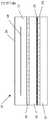
반도체 공정의 기술에서, 예를 들어, 척이나 서셉터는 공정 중에 기판(또는 웨이퍼)을 유지하고 균일한 온도 프로파일을 상기 기판에 제공하기 위해 사용된다. 도 1을 참조하면, 정전척을 위한 지지 어셈블리(support assembly)(10)가 도시되는데, 상기 지지 어셈블리는 삽입 전극(embedded electrode)(14)이 있는 정전척(12), 및 전형적으로 실리콘 접착제(silicone adhesive)인 접착층(18)을 통해 상기 정전척(12)과 결합(bond)되는 히터 플레이트(16)를, 포함한다. 히터(20)는 상기 히터 플레이트(16)에 고정(secure)되고, 이는 예를 들어 에칭형 판상 히터(etched-foil heater)일 수 있다. 이 히터 어셈블리는, 다시 전형적으로 실리콘 접착제인 접착층(24)을 통하여 냉각 플레이트(22)에 결합(bond)된다. 상기 기판(26)은 상기 정전척(12) 상에 배치되고, 상기 전극(14)은 정전기 전력이 발생되도록 전압 소스(도시되지 않음)에 연결되는데, 이는 상기 기판(26)을 같은 자리에 고정한다. 라디오 주파수(RF) 또는 마이크로파 전원(미도시)은 상기 지지 어셈블리(10)를 포위하는 플라즈마 반응 챔버(plasma reactor chamber) 내부에서 상기 정전척(12)에 결합될 수 있다. 따라서 상기 히터(20)는 플라즈마 강화 막 증착(plasma enhanced film deposition) 또는 식각(etch)을 포함하는 다양한 챔버-내 플라즈마 반도체 공정 단계 동안에 상기 기판(26) 상의 온도를 유지하기 위해 필요한 열을 제공한다.In the art of semiconductor processing, for example, a chuck or susceptor is used to hold a substrate (or wafer) during processing and to provide a uniform temperature profile to the substrate. Referring to Figure 1, a
상기 기판(26) 공정의 모든 페이즈(phase)들 동안에, 총 공정 시간을 감소시키되, 식각(etch)되는 상기 기판(26) 내의 공정 변동들(processing variations)을 감소시키기 위해, 상기 정전척(12)의 온도 프로파일이 엄격하게 제어되는 것이 중요하다. 상기 기판 상의 온도 균일성을 향상시키기 위한 개선된 장치들 및 방법들은 다른 응용들 가운데서 반도체 공정 기술에 지속적으로 요망되었다.During all phases of the
본 개시의 한 형태에서, 적어도 하나의 유체 통로(passageway)를 구비한 베이스 멤버를 포함하는 장치가 제공된다. 2상유체는 상기 유체 통로 내에 배치되며, 상기 2상유체의 압력은, 상기 2상유체가 가열 및 냉각 중 적어도 하나를 상기 베이스 멤버에 제공하도록 제어된다. 튜닝층은 상기 베이스 멤버에 고정되며 복수 개의 영역들을 갖는다. 게다가 구성요소(component)가 상기 튜닝층에 고정된다.In one aspect of the present disclosure, an apparatus is provided that includes a base member having at least one fluid passageway. A two-phase fluid is disposed in the fluid passage, and the pressure of the two-phase fluid is controlled such that the two-phase fluid provides at least one of heating and cooling to the base member. The tuning layer is fixed to the base member and has a plurality of regions. In addition, a component is fixed to the tuning layer.
다른 형태에서는, 적어도 하나의 유체 통로를 구비한 베이스 멤버를 포함하는 히터가 제공된다. 2상유체는 상기 유체 통로 내에 배치되며, 상기 2상유체의 압력은, 상기 2상유체가 가열 및 냉각 중 적어도 하나를 상기 베이스 멤버에 제공하도록 제어된다. 튜닝 히터는 상기 베이스 멤버에 고정되며, 복수 개의 영역들을 포함한다. 추가적으로 척이 상기 베이스 멤버의 반대측에서 상기 튜닝 히터에 고정된다.In another aspect, a heater is provided that includes a base member having at least one fluid passageway. A two-phase fluid is disposed in the fluid passage, and the pressure of the two-phase fluid is controlled such that the two-phase fluid provides at least one of heating and cooling to the base member. The tuning heater is fixed to the base member and includes a plurality of regions. In addition, a chuck is fixed to the tuning heater on the opposite side of the base member.
또 다른 형태에서는, 적어도 하나의 유체 통로를 구비한 베이스 멤버를 포함하는 히터 시스템이 제공된다. 2상유체는 상기 유체 통로 내에 배치되는데, 상기 2상유체의 압력은, 상기 2상유체가 가열 및 냉각 중 적어도 하나를 상기 베이스 멤버에 제공하도록 제어된다. 튜닝층은 상기 베이스 멤버에 고정되며 복수 개의 영역들을 포함한다. 또한 제어 시스템으로서, 상기 튜닝층과 통신하는 전력선들의 복수 개의 세트들; 및 상기 전력선들 및 상기 튜닝층과 전기적으로 통신하는 어드레스 지정가능한(addressable) 복수 개의 제어 요소(control element)들을 구비하되, 상기 제어 요소는 상기 튜닝층 영역들의 선택적 제어를 제공하는, 제어 시스템도 제공된다.In another aspect, a heater system is provided that includes a base member having at least one fluid passageway. A two-phase fluid is disposed in the fluid passage, wherein the pressure of the two-phase fluid is controlled such that the two-phase fluid provides at least one of heating and cooling to the base member. The tuning layer is fixed to the base member and includes a plurality of regions. Further comprising: a plurality of sets of power lines in communication with the tuning layer; And a plurality of addressable control elements in electrical communication with the power lines and the tuning layer, wherein the control element provides selective control of the tuning layer regions do.
응용성에 있어 더 많은 영역들이 본 명세서에 제공된 설명으로부터 명백해질 것이다. 그 설명과 구체적인 예시들은 보여주기 위한 목적으로 의도되었을 뿐이고, 본 개시의 범위를 제한하기 위한 목적은 아니라는 것이 이해되어야 한다.Further areas of applicability will become apparent from the description provided herein. It is to be understood that the description and specific examples are intended for purposes of illustration only and are not intended to limit the scope of the disclosure.
본 개시서가 잘 이해될 수 있도록, 첨부의 도면들을 참조하여 개시서의 다양한 형태들이 예시적으로 설명될 것이다.
도 1은 선행기술의 정전척(electrostatic chuck)의 측면도이다.
도 2는 튜닝층을 구비하고 본 개시의 일 형태의 원리들에 따라 구성된, 히터의 부분 측면도이다.
도 3은 튜닝층 또는 튜닝 히터를 구비하고 본 개시의 원리들에 따라 구성된, 도 1의 히터의 다른 형태의 분해 측면도이다.
도 4는 본 개시의 원리들에 따른, 베이스 히터에 대한 4개의 영역들 및 튜닝 히터에 대한 18개의 영역들을 예시적으로 도시하는, 도 3의 히터의 사시 분해도(perspective exploded view)이다.
도 5는 보조적(supplemental) 튜닝층을 구비하고, 본 개시의 원리들에 따라 구성된 고정밀 히터 시스템의 다른 일 형태의 측면도이다.
도 6은 본 개시의 다른 일 형태에 따라 서로 오프셋된 교번(alternating) 튜닝층들의 분해 사시도(exploded perspective view)이다.
도 7은 본 개시의 일 형태에 따라, 상기 히터 척 어셈블리의 층들로 삽입(embed)된 제어 장치들의 사시도이다.
도 8은 본 개시의 원리들에 따라 구성된 독립적으로 제어가능한 히터 요소(element)들을 구비한 히터 시스템의 사시도이다.
도 9는 본 개시의 원리들에 따라 구성되고 상기 히터 시스템의 비아(via)들 도시하는, 도 8의 9-9 라인을 따라 취한 단면도이다.
도 10은 본 개시의 원리들에 따라 구성되고 상기 히터 시스템의 상부 베이스(upper base)를 도시하는, 도 8의 10-10 라인을 따라 취한 부분단면도이다.
도 11은 본 개시의 원리들에 따라 구성되고 상기 히터 시스템의 하부 베이스(lower base)를 도시하는, 도 8의 11-11 라인을 따라 취한 부분단면도이다.
도 12는 본 개시의 원리들에 따라 구성되고 상기 하부 베이스의 테이퍼 공동들(tapered cavities) 내부의 요소들을 도시하는, 도 11의 평면도이다.
도 13은 본 개시의 지침(teaching)들에 따라 구성되고 2상 유체(two-phase fluid)를 위한 유체 통로들을 구비한 베이스 멤버들을 지닌 고정밀 히터 시스템의 다른 일 형태의 단면도이다.
도 14는 본 개시의 다른 일 형태에 따라 구성된 복수 개의 지지 요소(element)들 도시하는 사시도이다.
도 15는 본 개시의 지침(teaching)들에 따른, 상기 지지 요소들을 도시하는 단면도이다.
도 16은 본 개시의 지침(teaching)들에 따른, 지지 요소의 확대 평면도이다.
도 17은 본 개시의 지침(teaching)들에 따라 구성된 히트 스프레더(heat spreader)들을 도시하는 사시도이다.
본 명세서에 설명된 도면들은 실례를 보여주기 위한 목적들을 위한 것일 뿐, 어떤 방법으로든 본 개시의 범위를 제한하기 위하여 의도된 것은 아니다.In order that this disclosure may be better understood, various forms of disclosure will be illustratively described with reference to the accompanying drawings.
Figure 1 is a side view of an electrostatic chuck of the prior art.
Figure 2 is a partial side view of a heater having a tuning layer and constructed in accordance with the principles of one form of the present disclosure;
Figure 3 is an exploded side view of another embodiment of the heater of Figure 1, comprising a tuning layer or tuning heater and configured in accordance with the principles of the present disclosure.
FIG. 4 is a perspective exploded view of the heater of FIG. 3 illustrating, illustratively, the four regions for the base heater and the eighteen regions for the tuning heater, in accordance with the principles of the present disclosure.
Figure 5 is a side view of another form of high-precision heater system having a supplemental tuning layer and constructed in accordance with the principles of the present disclosure;
Figure 6 is an exploded perspective view of alternating tuning layers offset from each other according to another aspect of the present disclosure.
Figure 7 is a perspective view of control devices embeded into layers of the heater chuck assembly, in accordance with an aspect of the present disclosure;
Figure 8 is a perspective view of a heater system with independently controllable heater elements constructed in accordance with the principles of the present disclosure;
9 is a cross-sectional view taken along line 9-9 of FIG. 8, shown in accordance with the principles of the present disclosure and illustrating the vias of the heater system.
10 is a partial cross-sectional view taken along line 10-10 of FIG. 8, constructed in accordance with the principles of the present disclosure and showing the upper base of the heater system.
FIG. 11 is a partial cross-sectional view taken along line 11-11 of FIG. 8, constructed in accordance with the principles of the present disclosure and showing the lower base of the heater system.
Figure 12 is a plan view of Figure 11, showing elements within the tapered cavities of the lower base constructed in accordance with the principles of the present disclosure;
13 is a cross-sectional view of another form of high-precision heater system having base members constructed in accordance with the teachings of the present disclosure and having fluid passages for two-phase fluid.
Figure 14 is a perspective view illustrating a plurality of support elements constructed in accordance with another aspect of the present disclosure.
15 is a cross-sectional view showing the support elements according to the teachings of the present disclosure;
Figure 16 is an enlarged plan view of a support element in accordance with the teachings of the present disclosure;
17 is a perspective view illustrating heat spreaders constructed in accordance with the teachings of the present disclosure;
The drawings described herein are for illustrative purposes only and are not intended to limit the scope of the disclosure in any way.
하기의 설명은 단지 사실상 예시적인 것에 지나지 않고, 본 개시, 본 출원 또는 사용들을 제한하기 위하여 의도된 것은 아니다. 예를 들어, 본 개시의 하기의 형태들은 반도체 공정에서의 사용을 위한 척들, 그리고 몇몇 사례들에서 정전척들에 관한 것이다. 그러나, 본 명세서에 제공된 히터들과 시스템들은 다양한 응용(application)들에 쓰여질 수 있으며, 반도체 공정 응용들로 제한되는 것은 아니다.The following description is merely exemplary in nature and is not intended to limit the present disclosure, the present application or uses. For example, the following aspects of the present disclosure relate to chucks for use in semiconductor processing, and in some instances, electrostatic chucks. However, the heaters and systems provided herein may be used in a variety of applications, and are not limited to semiconductor process applications.
도 2를 참조하면 본 개시의 일 형태는, 베이스 히터층(base heater layer)(52)을 포함하는 히터(50)로서, 상기 베이스 히터층은 거기에 삽입된(embedded) 적어도 하나의 히터 회로(54)를 갖는다. 상기 베이스 히터층(52)은, 그것을 통해 상기 히터 회로(54)를 전원(미도시)에 연결하기 위해 형성된 적어도 하나의 개구(aperture)(56) (또는 비아)를 갖는다. 상기 베이스 히터층(52)은 주된 가열(primary heating)을 제공하는 반면, 근접 배치된 튜닝 히터층(60)은 상기 히터(50)에 의해 제공되는 열분배의 미세 조정(fine tuning)을, 도시된 바와 같이 상기 히터층(52)에 제공한다. 상기 튜닝층(60)은 거기에 삽입된 복수 개의 가열 요소(heating element)들(62)을 포함하는데, 상기 가열 요소들은 독립적으로 제어된다. 적어도 하나의 개구(64)는 복수 개의 개별 가열 요소들(62)을 전원 및 컨트롤러(미도시)에 연결하기 위해 상기 튜닝층(60)을 통해 형성된다. 더 도시된 바와 같이, 라우팅층(routing layer)(66)은 상기 베이스 히터층(52)과 상기 튜닝층(60) 사이에 배치되며, 내부 공동(internal cavity)(68)을 한정(define)한다. 전기 리드(electrical lead)들의 제1 세트(70)는 상기 히터 회로(54)를 상기 전원에 연결하는데, 이는 상기 히터층 개구(56)를 통해 연장된다. 전기 리드들의 제2 세트(72)는 복수 개의 가열 요소들(62)을 상기 전원에 연결하고, 상기 라우팅층(66)의 상기 내부 공동(68) 및 상기 히터층(52)에 있는 개구(55)를 통해 연장한다. 상기 라우팅층(66)은 선택적이며, 상기 히터(50)는 상기 라우팅층(66)이 없이, 그 대신 상기 베이스 히터층(52) 및 튜닝 히터층(60)만을 가지고도 사용될 수 있다는 것이 이해되어야 할 것이다.2, one aspect of the present disclosure is directed to a heater 50 comprising a
다른 일 형태에서는, 열분배의 미세 조정을 제공하는 것보다는, 대안으로서 상기 튜닝층(60)이 상기 척(12)에서의 온도를 측정하기 위해 사용될 수 있다. 이 형태는 온도 종속 저항 회로들의 복수 개의 구역-특정적(area-specific)이고 면밀한(discreet) 위치들을 제공한다. 이 온도 센서들 각각은 멀티플렉싱(multiplexing) 스위칭 배열을 통하여 개별적으로 읽혀질 수 있는데, 그것들의 예시적인 형태들은 더욱 상세하게 아래에서 제시되며 이는 각 개별 센서들을 측정하기 위하여 요구되는 신호 전선(signal wire)들의 수에 비해 상대적으로 본질적으로 더 많은 센서들이 사용될 수 있도록 한다. 온도 감지 피드백(temperature sensing feedback)은, 예컨대 상기 기판(26)으로부터 상기 척(12)으로의 열 흐름(heat flux)을 조절하도록 이면(backside) 냉각 기체 압력의 특정 영역(zone)을 제어하기 위한, 제어 판단(decision)들에 관하여 필요한 정보를 제공할 수 있다. 이와 동일한 피드백이, 보조 냉각 유체 열교환기(ancillary cool fluid heat exchangers)들을 통한, 유체 온도를 냉각하는 플레이트(미도시)의 밸런싱(balancing) 및 베이스 가열 영역(base heating zone)들(54)의 온도 조절을 위해, 상기 베이스 히터(50) 근처에 설치된 온도 센서들을 교체하거나 증가(augment)시키는 데도 사용될 수 있다.In another form, the
일 형태에서는, 상기 베이스 히터층(50) 및 상기 튜닝 히터층(60)은 중간(medium) 온도 응용(application)들을 위해 폴리이미드 물질 내, 밀봉 히터 회로(54) 및 튜닝층 가열 요소들(62)로부터 형성되는데, 상기 중간 온도 응용은 일반적으로 250° C 이하이다. 더욱이, 상기 폴리이미드 물질은 열전도율을 증가시키기 위해 물질들로 도핑될 수 있다.In one aspect, the base heater layer 50 and the
다른 형태들에서는, 상기 베이스 히터층(50) 및/또는 튜닝 히터층(60)은 층 공정(layered process)에 의해 형성되는데, 상기 공정에서 상기 층은 특히 후막, 박막, 용사(溶射, thermal spraying) 또는 졸-겔(sol-gel)과 관련된 공정들을 사용하는, 기판이나 또다른 층(layer)에의 물질의 적용(application) 또는 축적(accumulation)을 통해 형성된다.In other embodiments, the base heater layer 50 and / or the
일 형태에서는, 상기 베이스 가열 회로(54)는 인코넬®(Inconel®)로부터 형성되며, 상기 튜닝층 가열 요소들(62)은 니켈 물질이다. 또 다른 형태에서는, 상기 튜닝층 가열 요소들(62)은, 상기 요소들이 일반적으로 “2선식 제어(two-wire control)”로 언급되는 히터들과 온도 센서들 양쪽 모두로 기능할 수 있도록, 충분한 저항온도계수(temperature coefficient of resistance)를 갖는 물질로 형성된다. 그러한 히터들과 그것들의 물질들은, 본 출원에 동반하여 공통적으로 양도되고 그 개시들이 본 명세서에 전체로서 참조 병합된, 미국 특허 제7,196,295호 및 출원중(pending) 미국 특허출원 제11/475,534호에 개시된다.In one aspect, the
상기 2선식 제어로, 본 개시의 다양한 형태들이, 상기 열임피던스(thermal impedance) 튜닝층(60)의 개별 요소들 각각에 인가되는 전압 및/또는 전류의 인지(knowledge) 또는 측정을 통한 상기 층 가열 요소들(62)에 대한 온도, 전력 및/또는 열임피던스 기반 제어(based control)를 포함하는데, 상기 개별 요소들은, 첫번째 예로, 이들 요소들 각각으로부터의 열 흐름 출력(heat flux output)과 동일하게, 또는 두번째 예로, 상기 요소 온도에 알려진 관계에, 상응하는 곱셈과 나눗셈을 통하여 전력 및 저항으로 변환된다. 이것들 모두는, 각 요소 상의 열임피던스 부하(load)를 계산하고 모니터링(monitor)하도록 사용되어, 오퍼레이터(operator) 또는 제어 시스템이, 사용 또는 유지보수(maintenance), 공정 오류들 및 장비 열화(equipment degradation)로 인한 상기 챔버 또는 척의 물리적 변화들로부터 기인할 수 있되 그것들에 제한되지는 않는 구역-특정적 열 변화(area-specific thermal change)들을 감지하고 보상하는 것을 가능케 한다. 선택적으로, 상기 열임피던스 튜닝층(60) 내 개별적으로 제어되는 가열 요소들 각각은, 동일하거나 상이한 특정 온도들에 대응하는 기준점 저항(setpoint resistance)으로 지정될 수 있으며, 이때 상기 특정 온도는, 기판 상의 상응하는 구역(area)들로부터 발생하여 상기 베이스 히터층(52)을 통과하는 상기 열흐름을 수정하거나 게이트 제어(gate)하여, 반도체 공정 중 상기 기판 온도를 제어한다.With this two-wire control, the various forms of the present disclosure can be used to determine the temperature and / or temperature of the layered
일 형태에서는, 상기 베이스 히터(50)는 예컨대, 실리콘(silicone) 접착제 혹은 심지어 감압 접착제(pressure sensitive adhesive)를 사용하여 척(51)에 결합(bond)된다. 따라서 상기 히터층(52)은 주된 가열을 제공하며, 상기 튜닝층(60)은, 균일하거나 바람직한 온도 프로파일이 상기 척(51)에 제공되고 따라서 상기 기판(미도시)에 제공되도록 상기 가열 프로파일(heating profile)을 미세 조정 또는 조절(adjust)한다.In one form, the base heater 50 is bonded to the
본 개시의 다른 일 형태에서는, 상기 튜닝층 가열요소들(62)이 스트레인 하중(strain load)들에 노출되었을 때의 상기 튜닝층 가열 요소들(62)의 열적 민감도를 향상시키기 위해, 상기 튜닝층 가열 요소들(62)의 열팽창계수(coefficient of thermal expansion: CTE)는 상기 튜닝 가열층 기판(60)의 열팽창계수(CTE)에 매치(match)된다. 2선식 제어에 대한 많은 적합한 물질들이 온도와 스트레인(strain) 모두에 대한 저항 민감도(resistance sensitivity)를 포함하는 저항기 온도 장치 (Resistor Temperature Device: RTD)들과 유사한 특성들을 보인다. 상기 튜닝층 가열 요소들(62)의 열팽창계수(CTE)를 상기 튜닝 히터층 기판(60)에 매치(match)하는 것은 상기 실제(actual) 가열 요소 상의 스트레인(strain)을 감소시킨다. 그리고 작동 온도들이 증가함에 따라, 스트레인 수준(strain level)들은 증가하는 경향이 있으며, 따라서 열팽창계수(CTE) 매치(matching)는 더 중요한 요소가 된다. 일 형태에서는, 상기 튜닝층 가열 요소들(62)은 약 15 ppm/ºC의 열팽창계수(CTE)를 갖는 고순도 니켈-철 합금이며, 그것을 둘러싸는 폴리이미드 물질은 약 16 ppm/ºC의 열팽창계수(CTE)를 갖는다. 이 형태에서는, 상기 튜닝 히터층(60)을 다른 층들에 결합하는 물질들은, 상기 튜닝 히터층(60)을 상기 척(12)의 다른 멤버(member)들로부터 물리적으로 분리(decouple)시키는 탄성 특성들을 보인다. 비교가능한(comparable) 열팽창계수(CTE)들을 지닌 다른 물질들도 본 개시의 범위 내에 속하는 한, 사용될 수 있다는 것이 이해되어야 할 것이다.In another aspect of the present disclosure, in order to improve the thermal sensitivity of the tuning
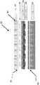
이제 도 3 내지 도 5를 참조하면, 베이스 히터층 및 튜닝층(위에 도 2에서 일반적으로 제시된 바와 같음)을 모두 구비한 히터의 한 예시적 형태가 도시되며, 참조번호(80)에 의해 일반적으로 표시된다. 상기 히터(80)는 베이스 플레이스(82)(냉각 플레이트(cooling plate)로서도 지칭됨)를 포함하는데, 이것은 일 형태에서는 약 16mm 두께의 알루미늄 플레이트이다. 일 형태에서는, 베이스 히터(84)는 도시된 바와 같이 탄성 결합층(elastomeric bond layer)(86)을 사용하여, 상기 베이스 플레이트(82)에 고정된다. 상기 탄성 결합은, 그 전체가 참조로서 본 명세서에 포함된, 미국 특허 제6,073,577호에 개시된 것일 수 있다. 본 개시의 일 형태에 따르면, 기판(88)은, 상기 베이스 히터(84)의 상단(top)에 배치되며 두께 약 1mm의 알루미늄 물질이다. 상기 기판(88)은 상기 베이스 히터(84)로부터 전력의 필요량을 분산(dissipate)시키기 위한 열전도율을 갖도록 설계된다. 상기 베이스 히터(84)는 열전도율의 필요량 없이 상대적으로 높은 전력을 갖기 때문에, 이 베이스 히터(84)는 (상기 저항성(resistive) 회로 트레이스(circuit trace)로부터) 인접한 구성요소(component)들 상에 “증거(witness)” 마크(mark)들을 남길 것이며, 결과적으로 전체 히터 시스템의 성능을 감소시킨다.Referring now to FIGS. 3-5, there is shown an exemplary embodiment of a heater with both a base heater layer and a tuning layer (as generally shown in FIG. 2 above), generally designated by the
튜닝 히터(90)는 상기 기판(88)의 상단에 배치되며, 위에서 제시된 바와 같이 탄성 결합층(94)을 사용하여 척(92)에 고정된다. 상기 척(92)은 일 형태에서는, 약 2.5mm의 두께를 가진 산화 알루미늄 물질(Aluminum Oxide material)이다. 본 명세서에 제시된 물질들과 치수(dimension)들은 단지 예시적인 것에 불과하고 따라서 본 개시는 본 명세서에 제시된 특정 형태들로 제한되지 않는다는 점이 이해되어야 할 것이다. 추가적으로, 상기 튜닝 히터(90)는 상기 베이스 히터(84)보다 낮은 전력을 갖고 있으며, 위에서 제시된 바와 같이 상기 기판(88)은, 상기 튜닝 히터(90) 상에 “증거(witness)” 마크(mark)들을 형성하지 않도록 상기 베이스 히터(84)로부터 전력을 분산시키는 기능을 한다.A tuning
상기 베이스 히터(84) 및 상기 튜닝 히터(90)는 더욱 상세하게 도 4에 도시되며, 여기서 상기 베이스 히터(84)를 위해 예시적인 4개의 영역(zone)들이 보여지고, 상기 튜닝 히터(90)를 위해 18개의 영역(zone)들이 보여진다. 일 형태에서, 상기 히터(80)는 450mm의 척 크기들과 함게 사용되도록 적응되나, 상기 열분배를 고도로 맞추는 그 능력으로 인해 더 크거나 더 작은 척 크기들과 함께 사용될 수 있다. 추가적으로, 상기 고정밀 히터(80)는 본 명세서에 도시된 바와 같은 적층/평면(stacked/planar) 구성에서보다는, (수평 평면을 가로질러) 상기 척의 표면 주변(영역(P)로 표시됨)에서, 또는 도 3, 튜닝층(90')의 수직 위치에 나란하게, 또는 상기 척을 가로지르거나 상기 척에 나란한 별개의 소정의 위치들에서, 또는 다른 주변 구성요소들 혹은 구성요소들의 조합들 표면 주위에서 사용될 수 있다. 또한 여전히 상기 고정밀 히터(80)는, 반도체 공정 장비(processing equipment) 내의 다른 구성요소들 중에서 공정 키트(process kit)들, 챔버 벽들, 두껑(lid)들, 기체 라인들 및 샤워헤드(showerhead)들에 사용될 수 있다. 본 명세서에 도시되고 설명된 상기 히터들 및 제어 시스템들은 많은 수의 응용들에서 사용될 수 있으며 따라서 상기 예시적 반도체 히터 척 응용(application)은 본 개시의 범위를 제한하는 것으로 간주되어서 아니된다는 사실이 이해되어야 할 것이다.The
본 개시는 또한 상기 베이스 히터(84) 및 상기 튜닝 히터(90)가 가열 기능에 제한되지 않는다는 점을 고려한다. 본 개시의 범위 내에 속하는 한, 각각 “베이스 기능층” 및 “튜닝층”으로 언급된, 이 멤버들 중 하나 이상은, 그 대체로서 온도 센서층(sensor layer) 또는 다른 기능 멤버(functional member)일 수 있다는 점이 이해되어야 할 것이다. 다른 기능(function)들은 예를 들어, 특히 다양한 전기적 특성들과 같은 센서 입력을 수집하는 진단층(diagnostic layer) 또는 냉각층(cooling layer)을 포함할 수 있다.The present disclosure also contemplates that the
도 5에 도시된 바와 같이, 상기 척(12)의 상단 표면 상의 부차적(secondary) 튜닝층 히터(120)의 포함과 함께 이중 튜닝 능력(dual tuning capability)이 제공될 수 있다. 상기 부차적 튜닝층은, 본 개시의 범위 내에 속하는 한, 가열층보다는 온도 감지층(sensing layer)으로 대체 사용될 수 있다. 따라서 임의의 수의 튜닝층 히터들이 사용될 수 있으며, 본 명세서에 도시되고 설명된 것들에 제한되지 않아야 한다.A dual tuning capability may be provided with the inclusion of a secondary
다른 일 형태에서는, 상기 베이스 기능층은, 전술한 바와 같은 상기 베이스 히터(84) 구성(construction) 대신 복수 개의 열전기적(thermoelectric) 요소들을 포함할 수 있다. 이 열전기적 요소들은 영역(zone)들 내에 배열될 수 있으며, 일반적으로 상기 베이스 플레이트 또는 냉각 플레이트(82)의 상단에 또는 근접하게 배치된다.In another form, the base functional layer may comprise a plurality of thermoelectric elements instead of the
또 다른 형태에서는, 상기 다수의(multiple) 튜닝층들은 “적층(stacked)” 구성(configuration)으로 사용되거나, 트레이스(trace)들 사이에 존재하는 갭(gap)들을 보상(compensate)하기 위해 반대 층들 상에서 개별 저항성 트레이스들이 인접(adjacent) 저항성 트레이스들로부터 오프셋(offset)되도록 수직으로 구성될 수 있다. 예를 들어, 도 6에 도시된 바와 같이, 제1 튜닝층(130)은, 튜닝층(140)의 트레이스들(142)이 상기 제1 튜닝층(130)의 트레이스들(134) 사이의 상기 갭들(132)에 인접하여 일렬로 배열되도록, 제2 튜닝층(140)으로부터 오프셋되며, 반대의 경우도 마찬가지이다. 또 다른 형태에서는, “체커판 형태의(checkerboard)” 설계가 인접한 층들 사이의 갭들이나 핫스팟(hot spot)들을 보상하기 위해 사용된다.In yet another form, the multiple tuning layers may be used in a " stacked " configuration or may be used to compensate for gaps present between the traces, The individual resistive traces may be vertically configured to be offset from the adjacent resistive traces. For example, as shown in FIG. 6, the
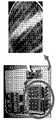
도 7을 참조하면, 일 형태에서, 회로를 가로지르는 문턱 전압이 초과될 때 한 방향으로 통전하는 별개의 고상 장치들(solid state devices)을 포함하는, 문턱 전압 스위칭 회로들은 패키징된 형태인 혹은 일반적으로 베어 다이(bare die) 구성요소들로서 삽입되며, 상기 히터 척의 몸체에 삽입(embed)되거나 부착(attach)된다. 다른 일 형태에서는, 상기 제어 요소(control element)들은 위에서 보여진 바와 같이 상기 결합층(bond layer)(86)에 삽입된다. 본 개시의 범위 내에 속하는 한, 상기 제어 요소들은 상기 구성요소(component)들이나 그것들의 어셈블리(assembly)들 어떤 것 내에 삽입될 수 있다는 것이 이해되어야 한다. 선택적으로, 단일 패키지 실리콘 제어 장치(single package silicon controls device)(ASIC) 상의 상기 문턱 전압 스위칭 회로들이 본 개시의 일 형태에 있어서의 상기 척에 삽입되거나 부착될 수 있다. 추가적인 제어 장치들(controls devices)도, 구성요소들 중 어떤 것이 작동 중 실패하는 경우의 여분을 제공하기 위해 사용될 수 있다.Referring to Figure 7, in one aspect, threshold voltage switching circuits, including separate solid state devices that energize in one direction when a threshold voltage across the circuit is exceeded, As bare die components and is embedded or attached to the body of the heater chuck. In another form, the control elements are inserted into the
도 8 내지 도 12에서 삽입 제어들(embedding controls)의 예시적인 하나의 형태가 도시된다. 보여지는 바와 같이 히터 시스템의 이러한 대안적 형태가 도시되고, 일반적으로 참조번호(200)에 의해 표시된다. 전술한 바와 같이 반도체 공정에 있어서 기판에 대한 균일한 온도 프로파일과 같은 고도로 맞춰진(highly tailored) 온도 프로파일을 가열 대상에 제공하기 위하여, 상기 히터 시스템(200)은 복수 개의 독립적으로 제어가능한 히터 요소들(202)를 포함하며, 그 작동은 아래에서 더욱 상세히 제시된다. 상부 베이스(204)는 상기 히터 요소들(202)에 근접 배치되며, 일 형태에서는, 상기 히터 요소들(202)은, 상기 상부 베이스(204)에 결합된 식각박(etched foil) 또는 상기 상부 베이스(204) 상에 퇴적(deposit)된 층을 이룬(layered) 히터와 같이, 상기 상부 베이스(204) 상에 배치된다. 상기 상부 베이스(204)는 복수 개의 테이퍼 공동들(206)을 한정하는데, 이것들은 상기 히터 요소들 각각과 정렬된다. 이 형태의 상기 테이퍼 공동들(206)은 도시된 바와 같이 상부 벽(208) 및 테이퍼 측벽들(210)을 포함한다. 상기 상부 베이스(204)는 아래에서 제시되는 바와 같이 전력 및 제어 선들에 대한 통로를 제공하기 위한 복수 개의 전력 비아(via)들(212)을 더 포함한다.An exemplary form of embedding controls is shown in Figures 8-12. As can be seen, this alternative form of heater system is shown and is generally indicated by
하부 베이스(220)는 상부 베이스(204)에 인접하며, 상기 상부 베이스(204)의 상기 테이퍼 공동들(206)과 정렬된 복수 개의 역 테이퍼 공동들(222)을 한정한다. 상기 역 테이퍼 공동들(222)은 마찬가지로 하부 벽(224)과 테이퍼 측벽들(226)을 한정한다. 상기 하부 베이스(220)는, 전력 및 제어 선들에 대한 통로로도 제공되며, 상기 상부 베이스(204)의 전력 비아들(212)과 통신하는, 복수 개의 전력 비아(via)들(228)을 더 포함한다.The
도 14에서 가장 잘 보여지는 바와 같이, 상기 공동들(206, 222)의 형태는, 상기 히터 요소들(202)로부터 냉각 플레이트(도 1의 요소(22)로 도시됨)로 효율적인 열전달을 제공하고, 또한 상기 히터 요소들(202)에 의해 제공되는 성능(performance) 및 온도 프로파일에 있어 상기 공동들과 그것들의 구성요소(component)들의 열충격을 감소시키도록 구성된다. 따라서, 상기 히터 요소들(202) 근처의 상기 공동의 “흔적(footprint)”은 더 작으며, 상기 냉각 플레이트(22)를 향해 상기 공동(206) 주변의 열 흐름을 이끌기(direct) 위해 상기 공동은 크기가 점차 더 커지고, 그리고 나서 상기 공동(222) 주변의 열 흐름을 상기 냉각 플레이트(22)를 향해 이끌기(direct) 위해 크기가 점차 감소한다. 상기 공동들(206 및 222)의 다른 형태(geometries)도 본 개시에 의해 제공될 수 있으며 따라서 상기 테이퍼(tapered) 구성들은 본 개시의 범위를 제한하는 것으로 간주되어서는 안된다는 점이 이해되어야 한다.14, the shape of the
더 나타난 바와 같이, 스위칭 요소들(230)과 제어 요소들(232)의 복수 개의 쌍들이 상기 하부 베이스(220)의 상기 역 테이퍼 공동들(222) 내에, 그리고 상기 복수 개의 히터 요소들(202)과 통신하도록 배치된다. 일반적으로 상기 스위칭 요소들(230) 및 제어 요소들(232)은, 상기 히터 요소들(202)의 작동을 제어하여, 전술한 바와 같이, 일 응용(application)에서 균일한 온도 프로파일인, 필요로 하는 온도 프로파일을 반도체 공정 장비(equipment)의 기판에 제공한다. 더욱 구체적으로, 일 형태에서는 상기 제어 요소는 마이크로프로세서이다. 다른 일 형태에서는, 상기 제어 요소는 전술한 바와 같은 상기 래스터 부스트(raster boost) 히터에 따른 회로이다. 일 형태에서는, 상기 제어 요소들(232)은 상기 히터 요소들(202)의 온도 제어를 위해 디지털 버스(234)를 통해 통신한다.A plurality of pairs of switching
상기 히터 시스템(200)은, 원하는 온도 프로파일을 위해 상기 히터 요소들(202) 각각에 적절한 제어 신호들을 보내는 상기 제어 요소들(232) 각각과 통신하는 멀티플렉서를 더 포함한다. 일 형태에서는, 상기 멀티플렉서(240)는 광학 버스(242)를 통해 전원(미도시)과 통신한다.The
게다가, 상기 히터 시스템(200)은 복수 개의 히터 요소들(202)에 근접 배치된 복수 개의 개별 온도 센서들(250)을 포함할 수도 있다. 한 대안적 형태에서, 상기 히터 요소들(202)은 본 개시의 다른 형태들에서 본 명세서에 제시된 바와 같이, 저항성 물질이 히터 및 온도 센서 양쪽 모두로 기능하도록 하는 충분한 저항온도계수 특성들을 갖고 있는 저항성 물질을 포함한다.In addition, the
정전척 응용(application)에서는, 상기 히터 시스템(200)은, 일 형태에서 디지털 버스(262)와 통신하는, RF 필터(260)를 더 포함한다.In electrostatic chuck application, the
본 명세서에 제시된 시스템들 중 임의의 것의 온도 캘리브레이션(calibration)은 표준 저항 측정기를 사용하여 첫째로 상기 튜닝층 히터들의 개별 저항들을 측정하는 것에 의해 수행된다. 독립적이거나 또는 상기 위의 방법에 추가적인, 다른 방법에서는, 상기 튜닝층 히터 요소들(62)은 일정한 온도로 유지되고, 정상 작동(normal operation)에서와 같이 펄스가 발생될 것이지만 짧은 지속시간 동안뿐일 것이며, 그리고 나서 상기 저항이 계산되어 상기 제어 시스템에 세팅될 것이다. 동일하거나 복수 개인 온도 포인트들에 있어 이런 반복적 테크닉은 제어를 위해 상기 시스템을 캘리브레이션(calibrate)할 것이다.The temperature calibration of any of the systems presented herein is performed by first measuring the individual resistances of the tuning layer heaters using a standard resistance meter. In other methods, which are independent or additional to the above methods, the tuning
이제 도 13을 참조하면, 히터 시스템의 다른 일 형태가 도시되며, 장치(300)로 일반적으로 표시된다. 본 개시의 일 형태에서의 히터인 상기 장치(300)는 적어도 하나의 유체 통로(fluid passageway)(320)를 구비한 베이스 멤버(310)를 갖는다. 다수의 유체 경로들(320)은 이 형태에서 도시되며, 본 개시의 또다른 형태에서 상기 통로들(320)은 영역(zone)들(위에서 제시된 바와 같은 히터 영역들과 같은 것)을 더 한정할 수 있다. 2상 유체(325)는 상기 유체 통로들(320) 내부에 배치되며, 2상유체(325)가 상기 베이스 멤버(310)에 가열을 제공하도록 2상유체(325)의 압력이 제어된다. 이 시스템은 예를 들어, 그 전체가 참조로써 본 명세서에 내용이 포함된, 미국 특허 제7,178,353호 및 제7,415,835호, 그리고 공개된 미국 특허출원 제20100076611호에 더 상세하게 설명된다. 일반적으로 이 시스템들에, 가압된 냉각제(pressurized refrigerant)가 응축된 액체(condensed liquid)로서 또한 기체 상태로서 제공된다. 상기 응축된 액체는 증기 혼합물(vaporous mix)로 팽창되며, 그 압력에 의해 결정된 목표(target) 온도에 도달하게끔 기체 냉각제가 추가된다. 따라서 온도 조정(correction)들은 기체 압력 조정들에 의해 매우 빠르게 이루어질 수 있다. 그러한 시스템들은 어드밴스드 써멀 사이언스즈 주식회사(Advanced Thermal Sciences Corporation)에 의해 제공되며, 본 개시의 지침(teaching)들과 함께 사용될 수 있다.Referring now to FIG. 13, another form of heater system is shown and generally indicated by
더 보여지는 바와 같이, 튜닝층(330)은, 예를 들어 접착층(332)과 함께 상기 베이스 멤버(310)에 고정되며, 이때 상기 튜닝층(330)은 복수 개의 영역(zone)들(335)을 포함하도록 한다. 이 튜닝층(330)은 위에서 제시된 상기 튜닝층들 및 히터들과 유사하며, 그런 점에 있어 명확화의 목적을 위하여 다시 상세하게 설명되지 않을 것이다. 위에서 제시된 형태들과 유사하게, 상기 튜닝층(335)은 상기 베이스 멤버(310)보다 더 낮은 전력을 가진다. 그리고 더 도시된 바와 같이, 구성요소(340)는 예시에서와 같이, 척, 받침대(pedestal), 웨이퍼 테이블, 기판 지지체(support) 또는 샤워헤드가 상기 튜닝층(330)에 고정된다. 본 명세서에 사용된 바와 같이, “구성요소(component)”는 공정을 위해 직접적으로 또는 간접적으로 지지되는 웨이퍼가 그 위에 있는 어떤 멤버나 어셈블리(assembly)를 뜻하는 것으로 간주되어서는 안 된다.The
일 형태에서는, 상기 튜닝층(330)은 히터이고, 또다른 일 형태에서는, 상기 튜닝층(330)은 온도 센서이며, 위에서 상세하게 제시된 바와 같다. 이 튜닝층(330) 및 또한 상기 베이스 멤버(310)는 그것들이 히터로서와 온도 센서로서 모두 기능할 수 있도록 하는 충분한 TCR 특성들을 가진 물질로 설계될 수 있다. 추가적으로, 부차적 튜닝층(도 5에 도시됨)이 구성요소(340)의 상단 표면에 고정되며, 또한 본 개시의 범위 내에 속하는 한, 히터들 및/또는 온도 센서들로서 기능하는 임의의 수의 튜닝층들이 사용될 수 있다는 것이 이해되어야 한다. 상기 구성요소(340)의 상단 표면에 고정된 상기 부차적 튜닝층과 함께, 웨이퍼가, 상기 구성요소(340)의 상단 표면 상에 상기 웨이퍼가 있을 때 직접적인 것에 비하여, 간접적으로 지지될 것이다.In one form, the
상기 장치(300)는 다수의 전력선들을 수용하기 위해 도 2에 도시된 바와 같이 상기 라우팅층(routing layer)(66)을 사용할 수도 있다. 본 개시의 범위 내에 속하는 한, 본 명세서에서 도면들을 통하여 제시된 바와 같이 추가적인 특징들이 유체 경로들(320)과 함께 베이스 멤버(310)를 구비한 본 개시의 이 형태와 함께 사용될 수도 있다.The
이제 도 14 내지 도 16을 참조하면, 본 개시의 다른 일 형태가 제조(manufacture) 중 필요한 평면도(flatness)를 제공하기 위해 상기 튜닝 히터층과 상기 부스트(boost) 히터층 사이에 제공되는 복수 개의 지지 요소(support element)들(600)을 포함하는데, 이 형태에서 상기 제조(manufacture)는 프레스 공정이다. 더욱 구체적으로는, 본 개시의 이 형태에 있어서, 상기 지지 요소들(600)은 히터 회로를 가진 구리 층(602)으로 식각된다. 도 14에 보여지는 바와 같이, 상대적으로 큰 공간이 상기 구리 층(602) 내 트레이스들 사이에 존재하는데, 이들은 비평면 래미네이트(laminate) 또는 바람직하지 못한 평면도를 지닌 래미네이트에 기여하는 다소의 빈 공간(a void)이다. 지지 요소들(600)을 제공함으로써 평면도를 향상시키기 위한 추가적인 구조가 제공된다. 그리고 도 16에 도시된 바와 같이, 상기 지지 요소들(600)은, “분할된(split)” 구성으로 되어 있거나, 또는 그들 사이에 개구(opening)(610)를 갖는 두 부분(portion)들(602 및 604)을 포함한다. 그것으로써, 상기 접착제(adhesive)(620)(도 15에 도시됨)는 각각의 상기 지지 요소들(600) 사이에서 더욱 더 고르게 흐르도록 허용된다.Referring now to Figures 14-16, another aspect of the present disclosure provides a method of forming a plurality of supports (not shown) provided between the tuning heater layer and the boost heater layer to provide the necessary flatness during manufacture.
도 17에 보여지는 바와 같이, 개별 요소들(720)을 가로지르는 온도 균일성을 제공하기 위해 각각의 상기 요소들(720) 상에, 상응하는 복수의 히트 스프레더(heat spreader)들(710)이 배치되는 튜닝 히터(700)의 다른 일 형태가 도시된다. 상기 히트 스프레더들은, 알루미늄, 구리 및 열분해 흑연 시트(Pyrolytic Graphite Sheet: PGS)를 포함한 열분해 흑연을 포함하지만 이에 제한되지는 않는 다양한 물질들로 될 수 있다. 일 형태에서, 상기 히트 스프레더들(710)은 보여지는 바와 같이 모놀리식(monolithic)이며 일정한 두께를 갖는 구성일 수 있다. 그러나, 본 개시의 범위 내에 속하는 한, 일체형 홈(integral groove)들 또는 열 가이드(heat guide)들을 포함하는 다른 구성들(730)이 또한 제공될 수 있다는 것이 이해되어야 한다.A corresponding plurality of
본 명세서에 제시된 각각의 상기 튜닝층들/히터들은 제어 시스템에 의해 제어되며, 상기 제어 시스템의 다양한 형태들은, 여기에 동반하여 제출되고 공통적으로 본 출원에 지정된, “System and Method for Controlling a Thermal Array”이라는 제목의 공동-계속중인 특허출원들 및 “Thermal Array System”이라는 제목의 출원들에서 더욱 상세히 제시된다. 일반적으로, 상기 제어 시스템들은 상기 튜닝층과 통신하는 복수 개의 전력선들 및 상기 전력선들과 상기 튜닝층과 전기적으로 통신하는 어드레스 지정가능한(addressable) 복수 개의 제어 요소들을 구비하되, 상기 제어 요소들은 상기 튜닝층 영역들의 선택적 제어를 제공한다. 상기 제어 요소들은 예를 들어 문턱 전압 스위칭 회로들일 수 있으며, 이것들은 반도체 스위치들일 수 있다. 상기 문턱 전압 스위칭 회로들은 패키징될 수 있으며, 예를 들어 주문형 반도체(Application Specific Integrated Circuit: ASIC)로 될 수 있다. 뿐만 아니라, 상기 제어 요소들은 위에서 제시된 바와 같이 상기 척과 같은 구성요소 내에 삽입될 수 있다. 이 제어 시스템들 및 그것들의 관련된 알고리즘들은 위에서 제시된 공동-계속중 특허출원들에서 더 상세하게 설명되고 도시되며, 따라서 명확화의 목적을 위하여 본 명세서에 포함되지 않을 것이다.Each of the tuning layers / heaters presented herein is controlled by a control system, and various aspects of the control system are described in commonly assigned US patent application Ser. Quot; and co-pending patent applications entitled " Thermal Array System ". Generally, the control systems comprise a plurality of power lines in communication with the tuning layer and a plurality of addressable addressable control elements in electrical communication with the power lines and the tuning layer, To provide selective control of layer areas. The control elements may be, for example, threshold voltage switching circuits, which may be semiconductor switches. The threshold voltage switching circuits may be packaged and may be, for example, an application specific integrated circuit (ASIC). In addition, the control elements can be inserted into a component such as the chuck as shown above. These control systems and their associated algorithms are described and illustrated in greater detail in co-pending patent applications, supra, and will therefore not be included herein for purposes of clarity.
상기 개시는 예시들로서 설명되고 도시된 상기 실시예들에 한정되지 않음을 유의해야 한다. 광범위한 수정들이 설명되어 왔으며, 더 많은 것들도 당업자가 가진 지식의 부분들이다. 이것들 및 그 이상의 수정들도 기술적 균등물들에 의한 어떤 교체와 마찬가지로, 본 개시 및 본 특허의 보호범위를 이탈함 없이 상기 설명과 도면들에 추가될 수 있다.It should be noted that the disclosure is not limited to the embodiments described and illustrated by way of example. A wide range of modifications have been described, and many more are also part of the knowledge of those skilled in the art. These and further modifications, as well as any replacement by the technical equivalents, may be added to the above description and drawings without departing from the scope of the present disclosure and the present patent.
Claims (30)
Translated fromKorean적어도 하나의 유체 통로를 포함한 베이스 멤버;
상기 유체 통로 내에 배치된 2상유체로서, 응축된 액체 및 가스로서 제공되는 가압된 냉각제로 이루어진, 2상유체;
상기 베이스 멤버에 고정된 튜닝층으로서, 복수의 영역들을 한정하고 독립적으로 제어가능한 복수의 저항성 가열 요소들을 포함하는, 튜닝층; 및
상기 튜닝층에 고정된 구성요소(component);를 포함하며,
상기 2상유체의 압력은 상기 2상유체가 가열 및 냉각 중 적어도 하나를 상기 베이스 멤버에 제공하도록 제어되고,
상기 튜닝층은 상기 베이스 멤버가 상기 구성요소에 제공하는 열전달보다 더 적은 열전달을 상기 구성요소에 제공하고, 상기 베이스 멤버가 상기 구성요소에 주된 가열 또는 주된 냉각을 제공할 때, 상기 튜닝층은 상기 구성요소에서의 요망되는 열분배와 상기 베이스 멤버에 의하여 상기 구성요소로 제공되는 실제 열분배에 따라서 상기 복수의 영역들에서 상이한 양의 열을 선택적으로 발생시켜서, 상기 베이스 멤버에 의하여 상기 구성요소에 제공되는 실제 열분배를 미세 조정(fine tuning)하는, 장치.As an apparatus,
A base member including at least one fluid passage;
A two-phase fluid disposed in the fluid passage, the two-phase fluid comprising a pressurized coolant provided as condensed liquid and gas;
A tuning layer secured to the base member, the tuning layer comprising a plurality of resistive heating elements that define a plurality of regions and are independently controllable; And
And a component fixed to the tuning layer,
Wherein the pressure of the two-phase fluid is controlled so that the two-phase fluid provides at least one of heating and cooling to the base member,
Wherein the tuning layer provides less heat transfer to the component than the heat transfer that the base member provides to the component and when the base member provides primary heating or primary cooling to the component, Selectively generating different amounts of heat in the plurality of regions in accordance with the desired heat distribution in the component and the actual heat distribution provided by the base member to the component, And fine tuning the actual heat distribution provided.
상기 베이스 멤버는, 상기 2상유체를 포함하는 복수 개의 유체 통로들을 포함하며,
상기 복수 개의 통로들은 영역들을 한정하고
상기 베이스 멤버의 영역들의 수는 상기 튜닝층의 영역들의 수보다 적은,
장치.The method according to claim 1,
Wherein the base member comprises a plurality of fluid passages comprising the two-phase fluid,
The plurality of passageways define regions
Wherein the number of regions of the base member is less than the number of regions of the tuning layer,
Device.
상기 튜닝층은 히터 및 온도 센서 중의 하나인, 장치.The method according to claim 1,
Wherein the tuning layer is one of a heater and a temperature sensor.
상기 구성요소는 척, 받침대(pedestal), 웨이퍼 테이블, 기판 지지체 및 샤워헤드로 구성된 군에서 선택되는, 장치.The method according to claim 1,
Wherein the component is selected from the group consisting of a chuck, a pedestal, a wafer table, a substrate support, and a showerhead.
상기 튜닝층은, 상기 튜닝층이 히터 및 온도 센서 양쪽으로 기능할 수 있도록 하는, 충분한 저항온도계수(temperature coefficient of resistance; TCR) 특성들을 갖는 저항성 물질을 포함하는, 장치The method according to claim 1,
Wherein the tuning layer comprises a resistive material having a sufficient temperature coefficient of resistance (TCR) characteristics that allows the tuning layer to function on both the heater and the temperature sensor.
상기 구성요소의 상단 표면에 고정된 부차적 튜닝층(secondary tuning layer)을 더 포함하는, 장치.The method according to claim 1,
And a secondary tuning layer secured to an upper surface of the component.
복수 개의 튜닝층들을 더 포함하는, 장치.The method according to claim 1,
And further comprising a plurality of tuning layers.
상기 베이스 멤버와 상기 튜닝층 사이에 배치되고 전력선들을 라우팅하기 위해 내부 공동을 한정하는 라우팅층(routing layer)을 더 포함하는, 장치.The method according to claim 1,
And a routing layer disposed between the base member and the tuning layer and defining an inner cavity for routing power lines.
적어도 하나의 유체 통로들 및 상기 튜닝층은 상기 구성요소의 주변에 배치되는, 장치.The method according to claim 1,
Wherein at least one fluid passages and the tuning layer are disposed around the component.
상기 장치는,
상기 튜닝층에 근접 배치되고, 상기 영역들 각각과 정렬된 복수 개의 테이퍼 공동들을 한정하는, 상부 멤버; 및
상기 상부 멤버에 인접하고, 상기 상부 멤버의 상기 테이퍼 공동들과 정렬된 복수 개의 역 테이퍼 공동들을 한정하는, 하부 멤버를
더 포함하되,
상기 상부 멤버는 복수 개의 전력 비아(power via)들을 더 포함하고,
상기 하부 멤버는 상기 상부 멤버의 상기 전력 비아들과 통신하는 복수 개의 전력 비아들을 더 포함하며,
상기 하부 멤버의 상기 역 테이퍼 공동들 내에 제어 요소들이 배치되며, 상기 제어 요소들은 상기 튜닝층 및 상기 베이스 멤버 내부의 상기 2상유체를 위한 컨트롤러(controller) 중 적어도 하나와 통신하는,
장치.The method according to claim 1,
The apparatus comprises:
An upper member disposed proximate to the tuning layer and defining a plurality of tapered cavities aligned with each of the regions; And
A lower member adjacent the upper member and defining a plurality of reverse tapered cavities aligned with the taper cavities of the upper member,
Further included,
The upper member further comprising a plurality of power vias,
The lower member further comprising a plurality of power vias communicating with the power vias of the upper member,
Wherein control elements are disposed within the inverse tapered cavities of the lower member and wherein the control elements communicate with at least one of a controller for the two-phase fluid within the tuning layer and the base member.
Device.
상기 제어 요소들은 디지털 버스를 통하여 통신하는, 장치.11. The method of claim 10,
Wherein the control elements communicate via a digital bus.
Applications Claiming Priority (5)
| Application Number | Priority Date | Filing Date | Title |
|---|---|---|---|
| US201161528939P | 2011-08-30 | 2011-08-30 | |
| US61/528,939 | 2011-08-30 | ||
| US201261635310P | 2012-04-19 | 2012-04-19 | |
| US61/635,310 | 2012-04-19 | ||
| PCT/US2012/053137WO2013033394A2 (en) | 2011-08-30 | 2012-08-30 | High definition heater system having a fluid medium |
Publications (2)
| Publication Number | Publication Date |
|---|---|
| KR20140076556A KR20140076556A (en) | 2014-06-20 |
| KR101731566B1true KR101731566B1 (en) | 2017-04-28 |
Family
ID=47003204
Family Applications (10)
| Application Number | Title | Priority Date | Filing Date |
|---|---|---|---|
| KR1020177027998AActiveKR101941245B1 (en) | 2011-08-30 | 2012-08-30 | High definition heater |
| KR1020147008413AActiveKR101750406B1 (en) | 2011-08-30 | 2012-08-30 | Thermal array system |
| KR1020147008066AActiveKR101731566B1 (en) | 2011-08-30 | 2012-08-30 | High definition heater system having a fluid medium |
| KR1020147008067AActiveKR101914731B1 (en) | 2011-08-30 | 2012-08-30 | Method of manufacturing a high definition heater system |
| KR1020147008412AActiveKR101966305B1 (en) | 2011-08-30 | 2012-08-30 | Thermal array system |
| KR1020147008383AActiveKR101813635B1 (en) | 2011-08-30 | 2012-08-30 | System and method for controlling a thermal array |
| KR1020147008411AActiveKR101778718B1 (en) | 2011-08-30 | 2012-08-30 | Thermal array system |
| KR1020147008410AActiveKR101831439B1 (en) | 2011-08-30 | 2012-08-30 | System and method for controlling a thermal array |
| KR1020147008065AActiveKR101785503B1 (en) | 2011-08-30 | 2012-08-30 | High definition heater |
| KR1020177025252AActiveKR101868130B1 (en) | 2011-08-30 | 2012-08-30 | Thermal array system |
Family Applications Before (2)
| Application Number | Title | Priority Date | Filing Date |
|---|---|---|---|
| KR1020177027998AActiveKR101941245B1 (en) | 2011-08-30 | 2012-08-30 | High definition heater |
| KR1020147008413AActiveKR101750406B1 (en) | 2011-08-30 | 2012-08-30 | Thermal array system |
Family Applications After (7)
| Application Number | Title | Priority Date | Filing Date |
|---|---|---|---|
| KR1020147008067AActiveKR101914731B1 (en) | 2011-08-30 | 2012-08-30 | Method of manufacturing a high definition heater system |
| KR1020147008412AActiveKR101966305B1 (en) | 2011-08-30 | 2012-08-30 | Thermal array system |
| KR1020147008383AActiveKR101813635B1 (en) | 2011-08-30 | 2012-08-30 | System and method for controlling a thermal array |
| KR1020147008411AActiveKR101778718B1 (en) | 2011-08-30 | 2012-08-30 | Thermal array system |
| KR1020147008410AActiveKR101831439B1 (en) | 2011-08-30 | 2012-08-30 | System and method for controlling a thermal array |
| KR1020147008065AActiveKR101785503B1 (en) | 2011-08-30 | 2012-08-30 | High definition heater |
| KR1020177025252AActiveKR101868130B1 (en) | 2011-08-30 | 2012-08-30 | Thermal array system |
Country Status (11)
| Country | Link |
|---|---|
| US (13) | US10002779B2 (en) |
| EP (8) | EP2752082B1 (en) |
| JP (13) | JP6133869B2 (en) |
| KR (10) | KR101941245B1 (en) |
| CN (9) | CN104025702B (en) |
| AU (8) | AU2012301903B2 (en) |
| BR (8) | BR112014004907A2 (en) |
| CA (9) | CA2847342C (en) |
| IL (8) | IL231256A (en) |
| MX (8) | MX338214B (en) |
| WO (8) | WO2013033350A1 (en) |
Families Citing this family (140)
| Publication number | Priority date | Publication date | Assignee | Title |
|---|---|---|---|---|
| US20120154974A1 (en)* | 2010-12-16 | 2012-06-21 | Applied Materials, Inc. | High efficiency electrostatic chuck assembly for semiconductor wafer processing |
| US10163668B2 (en) | 2011-08-30 | 2018-12-25 | Watlow Electric Manufacturing Company | Thermal dynamic response sensing systems for heaters |
| WO2013033350A1 (en)* | 2011-08-30 | 2013-03-07 | Watlow Electric Manufacturing Company | Thermal array system |
| JP5973731B2 (en) | 2012-01-13 | 2016-08-23 | 東京エレクトロン株式会社 | Plasma processing apparatus and heater temperature control method |
| US8937800B2 (en)* | 2012-04-24 | 2015-01-20 | Applied Materials, Inc. | Electrostatic chuck with advanced RF and temperature uniformity |
| WO2014015886A1 (en) | 2012-07-26 | 2014-01-30 | Hewlett-Packard Development Company, L.P. | Electrical resistor heating |
| US10049948B2 (en)* | 2012-11-30 | 2018-08-14 | Lam Research Corporation | Power switching system for ESC with array of thermal control elements |
| WO2014164910A1 (en) | 2013-03-12 | 2014-10-09 | Applied Materials, Inc. | Multi zone heating and cooling esc for plasma process chamber |
| US10332772B2 (en) | 2013-03-13 | 2019-06-25 | Applied Materials, Inc. | Multi-zone heated ESC with independent edge zones |
| FR3007229B1 (en)* | 2013-06-17 | 2015-06-19 | Valeo Systemes Thermiques | CONTROL OF AN ELECTRIC HEATING CIRCUIT, IN PARTICULAR FOR A MOTOR VEHICLE |
| US20150016083A1 (en)* | 2013-07-05 | 2015-01-15 | Stephen P. Nootens | Thermocompression bonding apparatus and method |
| JP6100672B2 (en)* | 2013-10-25 | 2017-03-22 | 東京エレクトロン株式会社 | Temperature control mechanism, temperature control method, and substrate processing apparatus |
| TW201518538A (en) | 2013-11-11 | 2015-05-16 | Applied Materials Inc | Pixelated cooling, temperature controlled substrate support assembly |
| US10460968B2 (en) | 2013-12-02 | 2019-10-29 | Applied Materials, Inc. | Electrostatic chuck with variable pixelated magnetic field |
| US9518946B2 (en)* | 2013-12-04 | 2016-12-13 | Watlow Electric Manufacturing Company | Thermographic inspection system |
| US9716022B2 (en) | 2013-12-17 | 2017-07-25 | Lam Research Corporation | Method of determining thermal stability of a substrate support assembly |
| US9520315B2 (en) | 2013-12-31 | 2016-12-13 | Applied Materials, Inc. | Electrostatic chuck with internal flow adjustments for improved temperature distribution |
| US9622375B2 (en) | 2013-12-31 | 2017-04-11 | Applied Materials, Inc. | Electrostatic chuck with external flow adjustments for improved temperature distribution |
| US11158526B2 (en)* | 2014-02-07 | 2021-10-26 | Applied Materials, Inc. | Temperature controlled substrate support assembly |
| US9472410B2 (en) | 2014-03-05 | 2016-10-18 | Applied Materials, Inc. | Pixelated capacitance controlled ESC |
| JP6219227B2 (en)* | 2014-05-12 | 2017-10-25 | 東京エレクトロン株式会社 | Heater feeding mechanism and stage temperature control method |
| US9543171B2 (en) | 2014-06-17 | 2017-01-10 | Lam Research Corporation | Auto-correction of malfunctioning thermal control element in a temperature control plate of a semiconductor substrate support assembly that includes deactivating the malfunctioning thermal control element and modifying a power level of at least one functioning thermal control element |
| WO2016003633A1 (en) | 2014-07-02 | 2016-01-07 | Applied Materials, Inc | Apparatus, systems, and methods for temperature control of substrates using embedded fiber optics and epoxy optical diffusers |
| EP3167479B1 (en) | 2014-07-08 | 2021-12-01 | Watlow Electric Manufacturing Company | Bonded assembly with integrated temperature sensing in bond layer |
| KR101758087B1 (en) | 2014-07-23 | 2017-07-14 | 어플라이드 머티어리얼스, 인코포레이티드 | Tunable temperature controlled substrate support assembly |
| WO2016069808A1 (en)* | 2014-10-31 | 2016-05-06 | Watlow Electric Manufacturing Company | Thermal dynamic response sensing systems for heaters |
| CN104466840B (en)* | 2014-11-18 | 2017-01-18 | 河南省通信电缆有限公司 | Indoor wiring structure and wiring system using same |
| JP6202111B2 (en)* | 2014-11-20 | 2017-09-27 | 住友大阪セメント株式会社 | Electrostatic chuck device |
| JP6513938B2 (en)* | 2014-11-21 | 2019-05-15 | 日本特殊陶業株式会社 | Method of manufacturing electrostatic chuck |
| JP6325424B2 (en)* | 2014-11-21 | 2018-05-16 | 日本特殊陶業株式会社 | Electrostatic chuck |
| US20160149733A1 (en)* | 2014-11-26 | 2016-05-26 | Applied Materials, Inc. | Control architecture for devices in an rf environment |
| JP6530220B2 (en)* | 2015-03-30 | 2019-06-12 | 日本特殊陶業株式会社 | Ceramic heater and control method thereof, and electrostatic chuck and control method thereof |
| CN107636817B (en)* | 2015-05-22 | 2021-08-27 | 应用材料公司 | Azimuth adjustable multi-zone electrostatic chuck |
| US10386821B2 (en) | 2015-06-22 | 2019-08-20 | Lam Research Corporation | Systems and methods for calibrating scalar field contribution values for a limited number of sensors including a temperature value of an electrostatic chuck and estimating temperature distribution profiles based on calibrated values |
| US9779974B2 (en) | 2015-06-22 | 2017-10-03 | Lam Research Corporation | System and method for reducing temperature transition in an electrostatic chuck |
| US10763142B2 (en) | 2015-06-22 | 2020-09-01 | Lam Research Corporation | System and method for determining field non-uniformities of a wafer processing chamber using a wafer processing parameter |
| US10381248B2 (en)* | 2015-06-22 | 2019-08-13 | Lam Research Corporation | Auto-correction of electrostatic chuck temperature non-uniformity |
| US10074512B2 (en)* | 2015-07-09 | 2018-09-11 | Applied Materials Israel Ltd. | System and method for setting a temperature of an object within a chamber |
| US10237916B2 (en)* | 2015-09-30 | 2019-03-19 | Tokyo Electron Limited | Systems and methods for ESC temperature control |
| US10186437B2 (en)* | 2015-10-05 | 2019-01-22 | Lam Research Corporation | Substrate holder having integrated temperature measurement electrical devices |
| US10631370B2 (en)* | 2015-10-30 | 2020-04-21 | Ngk Insulators, Ltd. | Member for semiconductor manufacturing apparatus, method for producing the same, and heater including shaft |
| US9826574B2 (en)* | 2015-10-28 | 2017-11-21 | Watlow Electric Manufacturing Company | Integrated heater and sensor system |
| US9623679B1 (en)* | 2015-11-18 | 2017-04-18 | Xerox Corporation | Electrostatic platen for conductive pet film printing |
| US9812342B2 (en)* | 2015-12-08 | 2017-11-07 | Watlow Electric Manufacturing Company | Reduced wire count heater array block |
| US10690414B2 (en)* | 2015-12-11 | 2020-06-23 | Lam Research Corporation | Multi-plane heater for semiconductor substrate support |
| US10582570B2 (en)* | 2016-01-22 | 2020-03-03 | Applied Materials, Inc. | Sensor system for multi-zone electrostatic chuck |
| US12270577B2 (en) | 2016-03-02 | 2025-04-08 | Watlow Electric Manufacturing Company | Heater bundles for thermal gradient compensation |
| EP3423689A1 (en) | 2016-03-02 | 2019-01-09 | Watlow Electric Manufacturing Company | Virtual sensing system |
| US10619888B2 (en) | 2016-03-02 | 2020-04-14 | Watlow Electric Manufacturing Company | Heater bundle for adaptive control and method of reducing current leakage |
| US10247445B2 (en) | 2016-03-02 | 2019-04-02 | Watlow Electric Manufacturing Company | Heater bundle for adaptive control |
| JP6226092B2 (en)* | 2016-03-14 | 2017-11-08 | Toto株式会社 | Electrostatic chuck |
| KR102513443B1 (en)* | 2016-03-15 | 2023-03-24 | 삼성전자주식회사 | electrostatic chuck and substrate processing apparatus including the same |
| US10973088B2 (en) | 2016-04-18 | 2021-04-06 | Applied Materials, Inc. | Optically heated substrate support assembly with removable optical fibers |
| JP6982126B2 (en)* | 2016-05-06 | 2021-12-17 | 日本特殊陶業株式会社 | Heating member and electrostatic chuck |
| KR102329513B1 (en)* | 2016-05-10 | 2021-11-23 | 램 리써치 코포레이션 | Connections between laminated heater and heater voltage inputs |
| US10340171B2 (en) | 2016-05-18 | 2019-07-02 | Lam Research Corporation | Permanent secondary erosion containment for electrostatic chuck bonds |
| US10690705B2 (en)* | 2016-06-15 | 2020-06-23 | Watlow Electric Manufacturing Company | Power converter for a thermal system |
| US11069553B2 (en)* | 2016-07-07 | 2021-07-20 | Lam Research Corporation | Electrostatic chuck with features for preventing electrical arcing and light-up and improving process uniformity |
| TWI664873B (en) | 2016-07-07 | 2019-07-01 | 美商瓦特洛威電子製造公司 | Heater bundle for adaptive control and method of reducing current leakage |
| JP6238097B1 (en)* | 2016-07-20 | 2017-11-29 | Toto株式会社 | Electrostatic chuck |
| US20180053666A1 (en)* | 2016-08-19 | 2018-02-22 | Applied Materials, Inc. | Substrate carrier with array of independently controllable heater elements |
| US10366867B2 (en) | 2016-08-19 | 2019-07-30 | Applied Materials, Inc. | Temperature measurement for substrate carrier using a heater element array |
| US10685861B2 (en) | 2016-08-26 | 2020-06-16 | Applied Materials, Inc. | Direct optical heating of substrates through optical guide |
| US10679873B2 (en)* | 2016-09-30 | 2020-06-09 | Ngk Spark Plug Co., Ltd. | Ceramic heater |
| US10708979B2 (en) | 2016-10-07 | 2020-07-07 | De-Ice Technologies | Heating a bulk medium |
| JP2018063974A (en)* | 2016-10-11 | 2018-04-19 | 東京エレクトロン株式会社 | Temperature controller, temperature control method, and placement table |
| JP6705063B2 (en)* | 2016-10-21 | 2020-06-03 | ワットロー・エレクトリック・マニュファクチャリング・カンパニー | Heater system |
| ES2673130B1 (en) | 2016-12-19 | 2019-03-28 | Bsh Electrodomesticos Espana Sa | DOMESTIC COOKING DEVICE FOR INDUCTION WITH A MATRIX OF HEATING ELEMENTS |
| ES2673131B1 (en) | 2016-12-19 | 2019-03-28 | Bsh Electrodomesticos Espana Sa | DOMESTIC COOKING DEVICE FOR INDUCTION WITH A MATRIX OF HEATING ELEMENTS |
| US10910195B2 (en) | 2017-01-05 | 2021-02-02 | Lam Research Corporation | Substrate support with improved process uniformity |
| JP6571880B2 (en)* | 2017-04-10 | 2019-09-04 | 日本特殊陶業株式会社 | Holding device |
| US11276590B2 (en) | 2017-05-17 | 2022-03-15 | Applied Materials, Inc. | Multi-zone semiconductor substrate supports |
| JP7158131B2 (en)* | 2017-05-30 | 2022-10-21 | 東京エレクトロン株式会社 | Stage and plasma processing equipment |
| US10363845B2 (en)* | 2017-05-30 | 2019-07-30 | Ford Global Technologies, Llc | Conductive system |
| JP6905399B2 (en)* | 2017-06-23 | 2021-07-21 | 新光電気工業株式会社 | Board fixing device |
| CN107300426B (en)* | 2017-06-23 | 2019-06-25 | 北京金风科创风电设备有限公司 | Temperature detection system and temperature detection method |
| KR102435888B1 (en)* | 2017-07-04 | 2022-08-25 | 삼성전자주식회사 | Electro-static chuck, apparatus for processing substrate and manufacturing method of semiconductor device using the same |
| CN109429382A (en)* | 2017-08-24 | 2019-03-05 | 江苏威能电气有限公司 | Fast heater |
| DE102018007624A1 (en)* | 2017-09-26 | 2019-04-11 | E.I. Du Pont De Nemours And Company | Heating elements and heaters |
| TWI829367B (en) | 2017-11-16 | 2024-01-11 | 日商東京威力科創股份有限公司 | Plasma processing apparatus, temperature control method, and temperature control program |
| US11236422B2 (en) | 2017-11-17 | 2022-02-01 | Lam Research Corporation | Multi zone substrate support for ALD film property correction and tunability |
| US10681778B2 (en)* | 2017-11-21 | 2020-06-09 | Watlow Electric Manufacturing Company | Integrated heater and method of manufacture |
| JP7303820B2 (en)* | 2017-11-21 | 2023-07-05 | ワトロー エレクトリック マニュファクチュアリング カンパニー | Multi-zone pedestal heater with no vias |
| US11083050B2 (en) | 2017-11-21 | 2021-08-03 | Watlow Electric Manufacturing Company | Integrated heater and method of manufacture |
| US10761041B2 (en) | 2017-11-21 | 2020-09-01 | Watlow Electric Manufacturing Company | Multi-parallel sensor array system |
| CN111902923B (en)* | 2018-02-09 | 2024-11-29 | 应用材料公司 | Semiconductor processing apparatus with improved temperature control |
| US11950329B2 (en)* | 2018-02-16 | 2024-04-02 | Niterra Co., Ltd. | Holding device |
| US20190320501A1 (en) | 2018-04-17 | 2019-10-17 | Watlow Electric Manufacturing Company | All aluminum heater |
| US10633742B2 (en) | 2018-05-07 | 2020-04-28 | Lam Research Foundation | Use of voltage and current measurements to control dual zone ceramic pedestals |
| CN112292489B (en)* | 2018-05-31 | 2021-11-09 | 瓦尔梅特股份有限公司 | Through-air drying and bonding system and method |
| KR20250048603A (en) | 2018-07-05 | 2025-04-09 | 램 리써치 코포레이션 | Dynamic temperature control of substrate support in substrate processing system |
| US11087962B2 (en)* | 2018-07-20 | 2021-08-10 | Lam Research Corporation | Real-time control of temperature in a plasma chamber |
| US11209878B2 (en)* | 2018-07-31 | 2021-12-28 | Taiwan Semiconductor Manufacturing Co., Ltd. | Discrete time loop based thermal control |
| US10872747B2 (en) | 2018-08-08 | 2020-12-22 | Lam Research Corporation | Controlling showerhead heating via resistive thermal measurements |
| US11183400B2 (en) | 2018-08-08 | 2021-11-23 | Lam Research Corporation | Progressive heating of components of substrate processing systems using TCR element-based heaters |
| CN112955379B (en) | 2018-08-27 | 2024-06-18 | 迪艾斯技术有限公司 | Deicing system |
| JP7112915B2 (en)* | 2018-09-07 | 2022-08-04 | 東京エレクトロン株式会社 | temperature control system |
| JP2022534141A (en)* | 2018-10-12 | 2022-07-28 | アプライド マテリアルズ インコーポレイテッド | Chamber lid with integrated heater |
| US20220005675A1 (en)* | 2018-11-20 | 2022-01-06 | Lam Research Corporation | Dual-phase cooling in semiconductor manufacturing |
| CN111383891B (en)* | 2018-12-29 | 2023-03-10 | 中微半导体设备(上海)股份有限公司 | Temperature control device for semiconductor processing equipment and temperature control method thereof |
| US11562913B2 (en)* | 2019-04-25 | 2023-01-24 | Watlow Electric Manufacturing Company | Multi-zone azimuthal heater |
| JP7299756B2 (en)* | 2019-05-24 | 2023-06-28 | 日本特殊陶業株式会社 | holding device |
| EP3981222B1 (en)* | 2019-06-07 | 2024-03-20 | Watlow Electric Manufacturing Company | System and method for calibrating a control system operating an electric heater |
| JP7292115B2 (en)* | 2019-06-07 | 2023-06-16 | 東京エレクトロン株式会社 | Temperature adjustment device and temperature control method. |
| US11533783B2 (en)* | 2019-07-18 | 2022-12-20 | Applied Materials, Inc. | Multi-zone heater model-based control in semiconductor manufacturing |
| US11515190B2 (en)* | 2019-08-27 | 2022-11-29 | Watlow Electric Manufacturing Company | Thermal diffuser for a semiconductor wafer holder |
| KR102612972B1 (en)* | 2019-10-11 | 2023-12-13 | 한온시스템 주식회사 | Cooling water heater and method for measuring current of cooling water heater |
| CN110940695B (en)* | 2019-11-28 | 2022-04-26 | 航天特种材料及工艺技术研究所 | A heat gathering device |
| DE102020000642A1 (en)* | 2019-12-17 | 2021-06-17 | Mahle International Gmbh | Electric heater and method of operating the electric heater |
| US11937516B2 (en)* | 2020-03-04 | 2024-03-19 | International Business Machines Corporation | Fabrication of a flux bias line local heating device |
| US12022749B2 (en) | 2020-03-04 | 2024-06-25 | International Business Machines Corporation | Flux bias line local heating device |
| CN111372336B (en)* | 2020-03-25 | 2021-10-26 | 广州智慧医疗科技有限公司 | Infrared electrothermal film and preparation method thereof |
| US11450546B2 (en)* | 2020-04-09 | 2022-09-20 | Applied Materials, Inc. | Semiconductor substrate support with internal channels |
| US11551951B2 (en) | 2020-05-05 | 2023-01-10 | Applied Materials, Inc. | Methods and systems for temperature control for a substrate |
| KR102440415B1 (en)* | 2020-05-07 | 2022-09-13 | 주식회사 유진테크 | A substrate support assembly for multi-zone temperature control and a plasma processing system comprising the substrate support assembly |
| JP7731373B2 (en)* | 2020-05-19 | 2025-08-29 | ワトロー エレクトリック マニュファクチュアリング カンパニー | Passive and active calibration methods for resistive heaters |
| KR102776505B1 (en) | 2020-07-09 | 2025-03-07 | 삼성전자주식회사 | Plasma processing apparatus and method of fabricating semiconductor device using the same |
| JP7578359B2 (en)* | 2020-07-10 | 2024-11-06 | 東京エレクトロン株式会社 | Mounting table device and substrate processing device |
| CN114496692B (en)* | 2020-11-11 | 2024-03-12 | 中微半导体设备(上海)股份有限公司 | Heating assembly, substrate bearing assembly and plasma processing device thereof |
| KR102578703B1 (en) | 2020-11-24 | 2023-09-18 | 세메스 주식회사 | Support unit, substrate treating appartus including the same and temperature control method |
| KR20220089390A (en)* | 2020-12-21 | 2022-06-28 | 세메스 주식회사 | Temperature adjustment apparatus |
| KR102287443B1 (en)* | 2020-12-22 | 2021-08-09 | 주식회사 오토콘시스템 | The temperature control system of heater of electrostatic chuck |
| KR20220095612A (en)* | 2020-12-30 | 2022-07-07 | 세메스 주식회사 | Heater array and apparatus for processing a substrate including a heater array |
| EP4272044B1 (en)* | 2020-12-31 | 2024-10-09 | Delta Design, Inc. | Integrated circuit testing device with coupled control of thermal system |
| US12317378B2 (en)* | 2021-02-04 | 2025-05-27 | Applied Materials, Inc. | Multi-zone heater control for wafer processing equipment |
| JP7407752B2 (en)* | 2021-02-05 | 2024-01-04 | 日本碍子株式会社 | wafer support stand |
| CN112986983B (en)* | 2021-02-06 | 2023-12-19 | 中国人民解放军国防科技大学 | A holographic penetration imaging radar clutter suppression method |
| KR102695408B1 (en)* | 2021-02-26 | 2024-08-16 | 세메스 주식회사 | Support unit and substrate treating apparatus including the same |
| KR20220127171A (en) | 2021-03-10 | 2022-09-19 | 와틀로 일렉트릭 매뉴팩츄어링 컴파니 | Heater bundles having variable power output within zones |
| KR20220127173A (en) | 2021-03-10 | 2022-09-19 | 와틀로 일렉트릭 매뉴팩츄어링 컴파니 | Heater bundle with local power switch |
| KR20220127174A (en) | 2021-03-10 | 2022-09-19 | 와틀로 일렉트릭 매뉴팩츄어링 컴파니 | Hit bundles with virtual sensing for thermal gradient compensation |
| KR20220127170A (en) | 2021-03-10 | 2022-09-19 | 와틀로 일렉트릭 매뉴팩츄어링 컴파니 | Heater bundle for thermal gradient compensation |
| KR102654892B1 (en)* | 2021-07-28 | 2024-04-05 | 세메스 주식회사 | Support unit, heating unit and substrate processing apparatus including the same |
| KR20230031569A (en)* | 2021-08-27 | 2023-03-07 | 세메스 주식회사 | Supporting unit and apparatus for treating substreate |
| KR102654890B1 (en)* | 2021-08-27 | 2024-04-05 | 세메스 주식회사 | Apparatus for treating substreates and temperature control method of heating elements |
| JP2023146610A (en) | 2022-03-29 | 2023-10-12 | Toto株式会社 | electrostatic chuck |
| WO2023235492A1 (en)* | 2022-06-01 | 2023-12-07 | Ignik Outdoors, Inc. | A system and method for controlling a portable heated product |
| WO2024048273A1 (en)* | 2022-08-29 | 2024-03-07 | 東京エレクトロン株式会社 | Plasma treatment device and temperature measurement method |
| CN119690165B (en)* | 2024-12-16 | 2025-05-27 | 中国人民解放军总医院第一医学中心 | Control optimization method for medicine constant temperature system |
| CN119916863B (en)* | 2025-04-01 | 2025-07-11 | 四川味滋美食品科技有限公司 | Temperature control method, system and storage medium for heating bottom materials |
Citations (2)
| Publication number | Priority date | Publication date | Assignee | Title |
|---|---|---|---|---|
| US20040232136A1 (en) | 2003-05-23 | 2004-11-25 | Dainippon Screen Mfg. Co., Ltd. | Heat-treating apparatus |
| US20080011737A1 (en) | 2006-06-07 | 2008-01-17 | Tokyo Electron Limited | Hot plate and process for producing the same |
Family Cites Families (162)
| Publication number | Priority date | Publication date | Assignee | Title |
|---|---|---|---|---|
| US1631484A (en)* | 1925-03-30 | 1927-06-07 | Hudson Heating Systems Inc | Electric heater |
| US2008541A (en)* | 1933-02-28 | 1935-07-16 | Drury T Boyd | Electric heating device |
| US2108964A (en)* | 1936-02-03 | 1938-02-22 | Nestle Lemur Company | Electrical circuit for hair waving machines |
| US2237808A (en)* | 1939-09-07 | 1941-04-08 | Edison General Elec Appliance | Water heater and control therefor |
| GB1256694A (en)* | 1968-03-18 | 1971-12-15 | ||
| US3659155A (en)* | 1969-03-03 | 1972-04-25 | Robertshaw Controls Co | Current sensing apparatus |
| US3584291A (en)* | 1969-07-30 | 1971-06-08 | Powers Regulator Co | Proportional electric heat control system |
| US3745308A (en)* | 1971-07-01 | 1973-07-10 | Heinemann Electric Co | Temperature control circuits |
| US3774151A (en)* | 1971-09-02 | 1973-11-20 | Allied Chem | Diagnostic firing circuit adapted for use with inflatable restraint systems in vehicles |
| US3752956A (en)* | 1972-05-03 | 1973-08-14 | Du Pont | Electrical resistance heating control circuit |
| SE373963B (en)* | 1973-06-14 | 1975-02-17 | Janson Sven Olof | |
| US3953711A (en)* | 1973-11-06 | 1976-04-27 | E.G.O. Elektro-Geraete Blanc Und Fischer | Cooking units |
| SE7806238L (en)* | 1977-07-02 | 1979-01-03 | Fischer Karl | ELECTRIC RADIATING HEATING ELEMENT, SPECIAL FOR GLASS CERAMIC COOKERS |
| US4316078A (en)* | 1978-01-09 | 1982-02-16 | Sweetheart Plastics, Inc. | Food serving system |
| DE2844650A1 (en)* | 1978-10-13 | 1980-04-17 | Schickedanz Willi | BREAD ROESTER |
| US4320285A (en)* | 1979-05-10 | 1982-03-16 | Koether Bernard G | Primary thermostat using cooking computer temperature probe with control transfer upon probe failure |
| US4339649A (en)* | 1980-06-03 | 1982-07-13 | Emhart Industries, Inc. | Apparatus and method for R-C time constant circuit |
| JPS58145084A (en)* | 1981-09-18 | 1983-08-29 | 国際技術開発株式会社 | Temperature control system for heater |
| DE3204598A1 (en)* | 1982-02-10 | 1983-08-18 | Bosch Siemens Hausgeraete | CIRCUIT ARRANGEMENT FOR HEATING ELEMENTS IN COOKER BASINS |
| DE3303449A1 (en)* | 1983-02-02 | 1984-08-02 | Siemens AG, 1000 Berlin und 8000 München | PROTECTIVE DEVICE FOR A SUPRAL-CONDUCTING SOLENOID COIL ARRANGEMENT |
| US4748445A (en)* | 1983-07-13 | 1988-05-31 | Citizen Watch Co., Ltd. | Matrix display panel having a diode ring structure as a resistive element |
| US4700051A (en)* | 1984-09-22 | 1987-10-13 | E.G.O. Elektro-Gerate Blanc U. Fischer | Radiant heater for cooking appliances |
| DE3577012D1 (en)* | 1985-06-18 | 1990-05-10 | Agfa Gevaert Nv | ELECTRIC HEATING CIRCUIT. |
| US4713525A (en)* | 1986-07-23 | 1987-12-15 | Kowah, Inc. | Microcomputer controlled instant electric water heating and delivery system |
| JP2659363B2 (en)* | 1986-09-09 | 1997-09-30 | 三菱電機株式会社 | Superconducting magnet device with emergency demagnetization device |
| JP2587233B2 (en) | 1987-04-24 | 1997-03-05 | 四国化工機株式会社 | Branding device |
| WO1988009054A1 (en)* | 1987-05-06 | 1988-11-17 | Labtam Limited | Electrostatic chuck using ac field excitation |
| JP2779950B2 (en)* | 1989-04-25 | 1998-07-23 | 東陶機器株式会社 | Method and apparatus for applying voltage to electrostatic chuck |
| US5001594A (en)* | 1989-09-06 | 1991-03-19 | Mcnc | Electrostatic handling device |
| US5023430A (en)* | 1989-09-08 | 1991-06-11 | Environwear, Inc. | Hybrid electronic control system and method for cold weather garment |
| US5105067A (en)* | 1989-09-08 | 1992-04-14 | Environwear, Inc. | Electronic control system and method for cold weather garment |
| US5280422A (en)* | 1990-11-05 | 1994-01-18 | Watlow/Winona, Inc. | Method and apparatus for calibrating and controlling multiple heaters |
| US5446576A (en)* | 1990-11-26 | 1995-08-29 | Donnelly Corporation | Electrochromic mirror for vehicles with illumination and heating control |
| US5325261A (en)* | 1991-05-17 | 1994-06-28 | Unisearch Limited | Electrostatic chuck with improved release |
| US5280434A (en)* | 1991-07-01 | 1994-01-18 | Thermoforming Technologies, Inc. | Heating system for thermoforming |
| JPH05326112A (en)* | 1992-05-21 | 1993-12-10 | Shin Etsu Chem Co Ltd | Layered ceramic heater |
| US5684669A (en)* | 1995-06-07 | 1997-11-04 | Applied Materials, Inc. | Method for dechucking a workpiece from an electrostatic chuck |
| US5493101A (en)* | 1993-12-15 | 1996-02-20 | Eaton Corporation | Positive temperature coefficient transition sensor |
| JP2651793B2 (en)* | 1993-12-20 | 1997-09-10 | 坂口電熱株式会社 | Ceramic fiber heater |
| JPH07199722A (en)* | 1993-12-29 | 1995-08-04 | Nippon Dennetsu Co Ltd | Temperature controller utilizing resistance change |
| US5459632A (en)* | 1994-03-07 | 1995-10-17 | Applied Materials, Inc. | Releasing a workpiece from an electrostatic chuck |
| IT1281843B1 (en)† | 1995-01-25 | 1998-03-03 | Meneghetti Ampelio & C S N C | CONTROL DEVICE ESPECIALLY FOR MULTI-PLATE INDUCTION COOKERS |
| JP3364063B2 (en)* | 1995-08-25 | 2003-01-08 | 本田技研工業株式会社 | Electric load abnormality detection device for vehicles |
| US5796074A (en)* | 1995-11-28 | 1998-08-18 | Applied Materials, Inc. | Wafer heater assembly |
| JPH09270454A (en)* | 1996-04-01 | 1997-10-14 | Kyocera Corp | Wafer holding device |
| AT1469U1 (en) | 1996-04-10 | 1997-05-26 | E & E Elektronik Gmbh | METHOD FOR DETERMINING ABSOLUTE HUMIDITY |
| US6108189A (en)* | 1996-04-26 | 2000-08-22 | Applied Materials, Inc. | Electrostatic chuck having improved gas conduits |
| JPH09326555A (en)* | 1996-06-05 | 1997-12-16 | Nippon Avionics Co Ltd | Joining device |
| US5802856A (en)* | 1996-07-31 | 1998-09-08 | Stanford University | Multizone bake/chill thermal cycling module |
| EP0827187A3 (en)* | 1996-08-26 | 2004-01-07 | Applied Materials, Inc. | Method and apparatus for cooling a workpiece using an electrostatic chuck |
| DE19650038A1 (en)* | 1996-12-03 | 1998-06-04 | Bosch Gmbh Robert | Method for operating a resistance heating element and device for carrying out the method |
| JP3502233B2 (en)* | 1997-03-10 | 2004-03-02 | シャープ株式会社 | Heater control device |
| JP3437410B2 (en)* | 1997-06-02 | 2003-08-18 | シャープ株式会社 | Heater control device |
| JPH11111823A (en)† | 1997-10-06 | 1999-04-23 | Dainippon Screen Mfg Co Ltd | Heat treatment device for substrate |
| US6023052A (en)* | 1997-11-07 | 2000-02-08 | Shell Oil Company | Heater control |
| US5880924A (en)* | 1997-12-01 | 1999-03-09 | Applied Materials, Inc. | Electrostatic chuck capable of rapidly dechucking a substrate |
| US6342997B1 (en)* | 1998-02-11 | 2002-01-29 | Therm-O-Disc, Incorporated | High sensitivity diode temperature sensor with adjustable current source |
| US6073577A (en) | 1998-06-30 | 2000-06-13 | Lam Research Corporation | Electrode for plasma processes and method for manufacture and use thereof |
| US7218503B2 (en)* | 1998-09-30 | 2007-05-15 | Lam Research Corporation | Method of determining the correct average bias compensation voltage during a plasma process |
| US6361645B1 (en)* | 1998-10-08 | 2002-03-26 | Lam Research Corporation | Method and device for compensating wafer bias in a plasma processing chamber |
| JP4040814B2 (en) | 1998-11-30 | 2008-01-30 | 株式会社小松製作所 | Disk heater and temperature control device |
| JP2000235886A (en)* | 1998-12-14 | 2000-08-29 | Tokyo Electron Ltd | Temperature controlling device and temperature controlling method for heating means |
| US6490146B2 (en)* | 1999-05-07 | 2002-12-03 | Applied Materials Inc. | Electrostatic chuck bonded to base with a bond layer and method |
| US20020036881A1 (en)* | 1999-05-07 | 2002-03-28 | Shamouil Shamouilian | Electrostatic chuck having composite base and method |
| JP2001059694A (en) | 1999-08-20 | 2001-03-06 | Zexel Valeo Climate Control Corp | Heat exchanger |
| JP4505169B2 (en) | 1999-09-29 | 2010-07-21 | 東京エレクトロン株式会社 | Multi-region resistance heater |
| JP2001126851A (en) | 1999-10-26 | 2001-05-11 | Keihin Sokki Kk | Heater unit for semiconductor wafer and 1t3 manufacturing method |
| WO2002091457A1 (en)* | 1999-12-09 | 2002-11-14 | Ibiden Co., Ltd. | Ceramic plate for semiconductor producing/inspecting apparatus |
| US6307728B1 (en)* | 2000-01-21 | 2001-10-23 | Applied Materials, Inc. | Method and apparatus for dechucking a workpiece from an electrostatic chuck |
| US6444957B1 (en)* | 2000-04-26 | 2002-09-03 | Sumitomo Osaka Cement Co., Ltd | Heating apparatus |
| US20020071293A1 (en)* | 2000-07-13 | 2002-06-13 | Eden Richard C. | Power semiconductor switching devices, power converters, integrated circuit assemblies, integrated circuitry, power current switching methods, methods of forming a power semiconductor switching device, power conversion methods, power semiconductor switching device packaging methods, and methods a of forming power transistor |
| JP4415467B2 (en)* | 2000-09-06 | 2010-02-17 | 株式会社日立製作所 | Image display device |
| US6632523B1 (en)* | 2000-09-28 | 2003-10-14 | Sumitomo Bakelite Company Limited | Low temperature bonding adhesive composition |
| US6581275B2 (en)* | 2001-01-22 | 2003-06-24 | Applied Materials Inc. | Fabricating an electrostatic chuck having plasma resistant gas conduits |
| US6508062B2 (en)* | 2001-01-31 | 2003-01-21 | Applied Materials, Inc. | Thermal exchanger for a wafer chuck |
| US20050211385A1 (en)* | 2001-04-30 | 2005-09-29 | Lam Research Corporation, A Delaware Corporation | Method and apparatus for controlling spatial temperature distribution |
| JP3713220B2 (en)* | 2001-06-15 | 2005-11-09 | 日本特殊陶業株式会社 | Ceramic heater |
| KR100431658B1 (en) | 2001-10-05 | 2004-05-17 | 삼성전자주식회사 | Apparatus for heating a substrate and apparatus having the same |
| ES2567796T3 (en) | 2001-10-12 | 2016-04-26 | Whirlpool Corporation | Cooktop with distributed discrete heating elements |
| JP3856293B2 (en)* | 2001-10-17 | 2006-12-13 | 日本碍子株式会社 | Heating device |
| JP3982674B2 (en)* | 2001-11-19 | 2007-09-26 | 日本碍子株式会社 | Ceramic heater, method for manufacturing the same, and heating device for semiconductor manufacturing apparatus |
| JPWO2003047312A1 (en)* | 2001-11-30 | 2005-04-14 | イビデン株式会社 | Ceramic heater |
| DE60232198D1 (en)* | 2001-11-30 | 2009-06-10 | Nxp Bv | FREQUENCY MODULATOR USING SWITCHED CAPACITIES |
| DE10392293T5 (en) | 2002-02-15 | 2005-09-22 | Lm Glasfiber A/S | Method and apparatus for detecting the presence of polymer in a wind turbine blade |
| JP2003258065A (en)* | 2002-02-27 | 2003-09-12 | Kyocera Corp | Wafer mounting stage |
| KR100658030B1 (en)* | 2002-04-10 | 2006-12-15 | 플랙스콘 컴패니, 인크. | Insensitive electroluminescent device and manufacturing method thereof |
| US7060991B2 (en) | 2002-04-11 | 2006-06-13 | Reilly Thomas L | Method and apparatus for the portable identification of material thickness and defects along uneven surfaces using spatially controlled heat application |
| US6884973B2 (en)* | 2002-08-09 | 2005-04-26 | Sunbeam Products, Inc. | Heating pad controller with multiple position switch and diodes |
| JP3833974B2 (en)* | 2002-08-21 | 2006-10-18 | 日本碍子株式会社 | Manufacturing method of heating device |
| JP4323232B2 (en)* | 2002-12-04 | 2009-09-02 | 芝浦メカトロニクス株式会社 | Electrostatic adsorption method, electrostatic adsorption device, and bonding device |
| EP1439739B1 (en)* | 2003-01-20 | 2009-09-23 | Whirlpool Corporation | Electric cooking hob and method for determining the location of cooking utensils on it |
| JP4347295B2 (en)* | 2003-04-18 | 2009-10-21 | 株式会社日立国際電気 | Semiconductor manufacturing apparatus and semiconductor device manufacturing method |
| CN2634776Y (en)* | 2003-08-12 | 2004-08-18 | 刘键 | Electric heating blanket |
| US7053560B1 (en)* | 2003-11-17 | 2006-05-30 | Dr. Led (Holdings), Inc. | Bi-directional LED-based light |
| US7196295B2 (en) | 2003-11-21 | 2007-03-27 | Watlow Electric Manufacturing Company | Two-wire layered heater system |
| US8680443B2 (en) | 2004-01-06 | 2014-03-25 | Watlow Electric Manufacturing Company | Combined material layering technologies for electric heaters |
| US7178353B2 (en) | 2004-02-19 | 2007-02-20 | Advanced Thermal Sciences Corp. | Thermal control system and method |
| US7697260B2 (en)* | 2004-03-31 | 2010-04-13 | Applied Materials, Inc. | Detachable electrostatic chuck |
| JP4761723B2 (en)* | 2004-04-12 | 2011-08-31 | 日本碍子株式会社 | Substrate heating device |
| US7116535B2 (en)* | 2004-04-16 | 2006-10-03 | General Electric Company | Methods and apparatus for protecting an MR imaging system |
| US7460604B2 (en)* | 2004-06-03 | 2008-12-02 | Silicon Laboratories Inc. | RF isolator for isolating voltage sensing and gate drivers |
| JP2005347612A (en) | 2004-06-04 | 2005-12-15 | Matsushita Electric Ind Co Ltd | Wafer tray and wafer burn-in unit, wafer level burn-in apparatus using the same, and semiconductor wafer temperature control method |
| US8071916B2 (en)* | 2004-06-28 | 2011-12-06 | Kyocera Corporation | Wafer heating apparatus and semiconductor manufacturing apparatus |
| US20060000551A1 (en)* | 2004-06-30 | 2006-01-05 | Saldana Miguel A | Methods and apparatus for optimal temperature control in a plasma processing system |
| JP4319602B2 (en)* | 2004-08-31 | 2009-08-26 | 株式会社日立製作所 | Superconducting magnet device with quench protection circuit |
| US7544251B2 (en)* | 2004-10-07 | 2009-06-09 | Applied Materials, Inc. | Method and apparatus for controlling temperature of a substrate |
| US8038796B2 (en)* | 2004-12-30 | 2011-10-18 | Lam Research Corporation | Apparatus for spatial and temporal control of temperature on a substrate |
| US7126092B2 (en)* | 2005-01-13 | 2006-10-24 | Watlow Electric Manufacturing Company | Heater for wafer processing and methods of operating and manufacturing the same |
| US8183504B2 (en)* | 2005-03-28 | 2012-05-22 | Tyco Electronics Corporation | Surface mount multi-layer electrical circuit protection device with active element between PPTC layers |
| US7332692B2 (en)* | 2005-05-06 | 2008-02-19 | Illinois Tool Works Inc. | Redundant control circuit for hot melt adhesive assembly heater circuits and temperature sensors |
| US7287902B2 (en) | 2005-06-07 | 2007-10-30 | The Boeing Company | Systems and methods for thermographic inspection of composite structures |
| US20060289447A1 (en) | 2005-06-20 | 2006-12-28 | Mohamed Zakaria A | Heating chuck assembly |
| KR100925033B1 (en)* | 2005-06-29 | 2009-11-04 | 와틀로 일렉트릭 매뉴팩츄어링 컴파니 | Smart layered heater surfaces |
| JP4763380B2 (en)* | 2005-08-25 | 2011-08-31 | 株式会社アルバック | Manufacturing method of adsorption device |
| US7551960B2 (en)* | 2005-09-08 | 2009-06-23 | Medtronic, Inc. | External presentation of electrical stimulation parameters |
| US20080260583A1 (en)* | 2005-09-23 | 2008-10-23 | Koninklijke Philips Electronics, N.V. | Micro-Fluidic Device Based Upon Active Matrix Principles |
| US8519566B2 (en)* | 2006-03-28 | 2013-08-27 | Wireless Environment, Llc | Remote switch sensing in lighting devices |
| US7669426B2 (en)* | 2006-05-11 | 2010-03-02 | Bio-Rad Laboratories, Inc. | Shared switching for multiple loads |
| JP5134533B2 (en)* | 2006-05-17 | 2013-01-30 | 積水化学工業株式会社 | Double-sided tape for fixing polishing pad |
| JP2007317772A (en)* | 2006-05-24 | 2007-12-06 | Shinko Electric Ind Co Ltd | Electrostatic chuck device |
| NL1031878C2 (en) | 2006-05-24 | 2007-11-27 | Netherlands Inst For Metals Re | Non-destructive testing. |
| US7501605B2 (en)* | 2006-08-29 | 2009-03-10 | Lam Research Corporation | Method of tuning thermal conductivity of electrostatic chuck support assembly |
| US7901509B2 (en)* | 2006-09-19 | 2011-03-08 | Momentive Performance Materials Inc. | Heating apparatus with enhanced thermal uniformity and method for making thereof |
| JP2008085283A (en) | 2006-09-26 | 2008-04-10 | Momentive Performance Materials Inc | Heating apparatus with enhanced thermal uniformity, and method for making thereof |
| US7445446B2 (en)* | 2006-09-29 | 2008-11-04 | Tokyo Electron Limited | Method for in-line monitoring and controlling in heat-treating of resist coated wafers |
| JP2008118052A (en)* | 2006-11-07 | 2008-05-22 | Shinko Electric Ind Co Ltd | Substrate heating device |
| TW200836625A (en) | 2007-03-13 | 2008-09-16 | Otsuka Pharma Co Ltd | Evaluation method for tissue-preserving liquid |
| CN101269790B (en)* | 2007-03-21 | 2010-08-25 | 台达电子工业股份有限公司 | Micro-electromechanical element and manufacturing method thereof |
| US8049112B2 (en)* | 2007-04-13 | 2011-11-01 | 3M Innovative Properties Company | Flexible circuit with cover layer |
| JP4898556B2 (en) | 2007-05-23 | 2012-03-14 | 株式会社日立ハイテクノロジーズ | Plasma processing equipment |
| JP2009054932A (en)* | 2007-08-29 | 2009-03-12 | Shinko Electric Ind Co Ltd | Electrostatic chuck |
| JP2009087928A (en)* | 2007-09-13 | 2009-04-23 | Semiconductor Energy Lab Co Ltd | Semiconductor device and manufacturing method thereof |
| US8680440B2 (en)* | 2007-09-14 | 2014-03-25 | T-Ink, Inc. | Control circuit for controlling heating element power |
| US9533006B2 (en)* | 2007-11-19 | 2017-01-03 | University Of Washington | Marine coatings |
| CN101903996B (en)* | 2007-12-21 | 2013-04-03 | 应用材料公司 | Method and apparatus for controlling temperature of a substrate |
| US8193473B2 (en)* | 2008-02-08 | 2012-06-05 | Ngk Insulators, Ltd. | Uniform temperature heater |
| US8092637B2 (en)* | 2008-02-28 | 2012-01-10 | Hitachi High-Technologies Corporation | Manufacturing method in plasma processing apparatus |
| CN101572850A (en)* | 2008-04-11 | 2009-11-04 | 王文 | Capacitance type microphone with stress release membrane prepared at a low temperature and preparation method thereof |
| JP5163349B2 (en) | 2008-08-01 | 2013-03-13 | 住友大阪セメント株式会社 | Electrostatic chuck device |
| JP5037465B2 (en)† | 2008-09-12 | 2012-09-26 | 株式会社オートネットワーク技術研究所 | Glow plug control device, control method, and computer program |
| US8532832B2 (en) | 2008-09-23 | 2013-09-10 | Be Aerospace, Inc. | Method and apparatus for thermal exchange with two-phase media |
| TW201017790A (en)* | 2008-10-17 | 2010-05-01 | Inotera Memories Inc | A furnace temperature flip method for thermal budget balance and minimum electric parameter variation |
| KR101644495B1 (en) | 2008-11-25 | 2016-08-01 | 쿄세라 코포레이션 | Wafer heating apparatus, electrostatic chuck, and method for manufacturing wafer heating apparatus |
| JP5185790B2 (en)* | 2008-11-27 | 2013-04-17 | 株式会社日立ハイテクノロジーズ | Plasma processing equipment |
| JP5250408B2 (en)* | 2008-12-24 | 2013-07-31 | 新光電気工業株式会社 | Substrate temperature adjustment fixing device |
| JP2010153730A (en)* | 2008-12-26 | 2010-07-08 | Omron Corp | Wiring structure, heater driving device, measuring device, and control system |
| US8092000B2 (en)* | 2009-01-19 | 2012-01-10 | Xerox Corporation | Heat element configuration for a reservoir heater |
| EP2402298B1 (en)* | 2009-02-20 | 2016-05-11 | NGK Insulators, Ltd. | Method of fabricating a ceramic-metal junction |
| US8400178B2 (en)* | 2009-04-29 | 2013-03-19 | Taiwan Semiconductor Manufacturing Company, Ltd. | Method and system of testing a semiconductor device |
| US7956653B1 (en)* | 2009-05-04 | 2011-06-07 | Supertex, Inc. | Complementary high voltage switched current source integrated circuit |
| US8785821B2 (en) | 2009-07-06 | 2014-07-22 | Sokudo Co., Ltd. | Substrate processing apparatus with heater element held by vacuum |
| CN101662888B (en) | 2009-09-28 | 2011-02-16 | 深南电路有限公司 | Preparation method for PCB plate with step trough |
| US8637794B2 (en)* | 2009-10-21 | 2014-01-28 | Lam Research Corporation | Heating plate with planar heating zones for semiconductor processing |
| CA2777870A1 (en)* | 2009-10-22 | 2011-04-28 | Datec Coating Corporation | Method of melt bonding high-temperature thermoplastic based heating element to a substrate |
| SG180882A1 (en)* | 2009-12-15 | 2012-07-30 | Lam Res Corp | Adjusting substrate temperature to improve cd uniformity |
| ES2388303B1 (en)† | 2010-03-03 | 2013-08-23 | BSH Electrodomésticos España S.A. | COOKING HOB WITH AT LEAST ONE COOKING AREA, AND PROCEDURE TO OPERATE A COOKING HOB. |
| US8791392B2 (en)* | 2010-10-22 | 2014-07-29 | Lam Research Corporation | Methods of fault detection for multiplexed heater array |
| US8546732B2 (en)* | 2010-11-10 | 2013-10-01 | Lam Research Corporation | Heating plate with planar heater zones for semiconductor processing |
| WO2013033350A1 (en)* | 2011-08-30 | 2013-03-07 | Watlow Electric Manufacturing Company | Thermal array system |
| US9324589B2 (en)* | 2012-02-28 | 2016-04-26 | Lam Research Corporation | Multiplexed heater array using AC drive for semiconductor processing |
| US8809747B2 (en)* | 2012-04-13 | 2014-08-19 | Lam Research Corporation | Current peak spreading schemes for multiplexed heated array |
| US20150016083A1 (en)* | 2013-07-05 | 2015-01-15 | Stephen P. Nootens | Thermocompression bonding apparatus and method |
- 2012
- 2012-08-30WOPCT/US2012/053069patent/WO2013033350A1/enactiveApplication Filing
- 2012-08-30BRBR112014004907Apatent/BR112014004907A2/ennot_activeIP Right Cessation
- 2012-08-30EPEP12773421.8Apatent/EP2752082B1/enactiveActive
- 2012-08-30CACA2847342Apatent/CA2847342C/enactiveActive
- 2012-08-30CNCN201280052496.6Apatent/CN104025702B/enactiveActive
- 2012-08-30USUS13/598,995patent/US10002779B2/enactiveActive
- 2012-08-30MXMX2014002424Apatent/MX338214B/enactiveIP Right Grant
- 2012-08-30AUAU2012301903Apatent/AU2012301903B2/ennot_activeCeased
- 2012-08-30AUAU2012301816Apatent/AU2012301816B2/ennot_activeCeased
- 2012-08-30EPEP12772150.4Apatent/EP2752079B1/enactiveActive
- 2012-08-30EPEP12773422.6Apatent/EP2752083A1/enactivePending
- 2012-08-30CNCN201280052655.2Apatent/CN104067691B/enactiveActive
- 2012-08-30CNCN201280052548.XApatent/CN103931270B/enactiveActive
- 2012-08-30WOPCT/US2012/053117patent/WO2013033381A2/enactiveApplication Filing
- 2012-08-30CACA2847279Apatent/CA2847279C/enactiveActive
- 2012-08-30AUAU2012301936Apatent/AU2012301936A1/ennot_activeAbandoned
- 2012-08-30MXMX2014002429Apatent/MX344029B/enactiveIP Right Grant
- 2012-08-30USUS13/599,781patent/US10049903B2/enactiveActive
- 2012-08-30JPJP2014528587Apatent/JP6133869B2/enactiveActive
- 2012-08-30AUAU2012301890Apatent/AU2012301890A1/ennot_activeAbandoned
- 2012-08-30USUS13/599,692patent/US9553006B2/enactiveActive
- 2012-08-30JPJP2014528585Apatent/JP6133868B2/enactiveActive
- 2012-08-30JPJP2014528582Apatent/JP6118322B2/enactiveActive
- 2012-08-30JPJP2014528579Apatent/JP5945327B2/enactiveActive
- 2012-08-30USUS13/598,956patent/US9123756B2/enactiveActive
- 2012-08-30AUAU2012301944Apatent/AU2012301944A1/ennot_activeAbandoned
- 2012-08-30MXMX2014002435Apatent/MX2014002435A/enactiveIP Right Grant
- 2012-08-30CNCN201280052498.5Apatent/CN103947287B/enactiveActive
- 2012-08-30AUAU2012301940Apatent/AU2012301940A1/ennot_activeAbandoned
- 2012-08-30BRBR112014004913Apatent/BR112014004913A2/ennot_activeIP Right Cessation
- 2012-08-30KRKR1020177027998Apatent/KR101941245B1/enactiveActive
- 2012-08-30USUS13/598,985patent/US9196513B2/enactiveActive
- 2012-08-30MXMX2014002431Apatent/MX338215B/enactiveIP Right Grant
- 2012-08-30KRKR1020147008413Apatent/KR101750406B1/enactiveActive
- 2012-08-30AUAU2012301952Apatent/AU2012301952A1/ennot_activeAbandoned
- 2012-08-30MXMX2014002432Apatent/MX337205B/enactiveIP Right Grant
- 2012-08-30USUS13/599,648patent/US9263305B2/enactiveActive
- 2012-08-30WOPCT/US2012/053058patent/WO2013033340A1/enactiveApplication Filing
- 2012-08-30KRKR1020147008066Apatent/KR101731566B1/enactiveActive
- 2012-08-30CNCN201710705400.6Apatent/CN107507791B/enactiveActive
- 2012-08-30CACA2847429Apatent/CA2847429C/enactiveActive
- 2012-08-30WOPCT/US2012/053054patent/WO2013033336A1/enactiveApplication Filing
- 2012-08-30WOPCT/US2012/053137patent/WO2013033394A2/enactiveApplication Filing
- 2012-08-30EPEP12769785.2Apatent/EP2752078B1/enactiveActive
- 2012-08-30EPEP12772154.6Apatent/EP2752085B1/enactiveActive
- 2012-08-30KRKR1020147008067Apatent/KR101914731B1/enactiveActive
- 2012-08-30WOPCT/US2012/053067patent/WO2013033348A1/enactiveApplication Filing
- 2012-08-30JPJP2014528603Apatent/JP6133871B2/enactiveActive
- 2012-08-30CACA2991157Apatent/CA2991157C/enactiveActive
- 2012-08-30KRKR1020147008412Apatent/KR101966305B1/enactiveActive
- 2012-08-30CNCN201280052730.5Apatent/CN103907395B/enactiveActive
- 2012-08-30KRKR1020147008383Apatent/KR101813635B1/enactiveActive
- 2012-08-30JPJP2014528599Apatent/JP6199865B2/enactiveActive
- 2012-08-30CACA2847284Apatent/CA2847284C/enactiveActive
- 2012-08-30BRBR112014004912Apatent/BR112014004912A2/ennot_activeApplication Discontinuation
- 2012-08-30MXMX2014002426Apatent/MX338005B/enactiveIP Right Grant
- 2012-08-30WOPCT/US2012/053049patent/WO2013033332A1/enactiveApplication Filing
- 2012-08-30BRBR112014004903Apatent/BR112014004903A2/ennot_activeIP Right Cessation
- 2012-08-30CNCN201280052543.7Apatent/CN103918347B/enactiveActive
- 2012-08-30EPEP12772556.2Apatent/EP2752081B2/enactiveActive
- 2012-08-30JPJP2014528598Apatent/JP6184958B2/enactiveActive
- 2012-08-30KRKR1020147008411Apatent/KR101778718B1/enactiveActive
- 2012-08-30BRBR112014004906Apatent/BR112014004906A2/ennot_activeIP Right Cessation
- 2012-08-30KRKR1020147008410Apatent/KR101831439B1/enactiveActive
- 2012-08-30CACA2847444Apatent/CA2847444C/enactiveActive
- 2012-08-30MXMX2014002427Apatent/MX340786B/enactiveIP Right Grant
- 2012-08-30JPJP2014528589Apatent/JP6133870B2/enactiveActive
- 2012-08-30BRBR112014004909Apatent/BR112014004909A2/ennot_activeApplication Discontinuation
- 2012-08-30BRBR112014004911Apatent/BR112014004911A2/ennot_activeIP Right Cessation
- 2012-08-30EPEP12772555.4Apatent/EP2752080B1/enactiveActive
- 2012-08-30CACA2847437Apatent/CA2847437C/enactiveActive
- 2012-08-30KRKR1020147008065Apatent/KR101785503B1/enactiveActive
- 2012-08-30KRKR1020177025252Apatent/KR101868130B1/enactiveActive
- 2012-08-30EPEP12769784.5Apatent/EP2769597B1/enactiveActive
- 2012-08-30CNCN201280052551.1Apatent/CN103959897B/enactiveActive
- 2012-08-30BRBR112014004901Apatent/BR112014004901A2/ennot_activeIP Right Cessation
- 2012-08-30CACA2847596Apatent/CA2847596C/enactiveActive
- 2012-08-30WOPCT/US2012/053148patent/WO2013033402A1/enactiveApplication Filing
- 2012-08-30MXMX2014002425Apatent/MX337204B/enactiveIP Right Grant
- 2012-08-30CNCN201280052769.7Apatent/CN103999545B/enactiveActive
- 2012-08-30USUS13/598,941patent/US9123755B2/enactiveActive
- 2012-08-30AUAU2012301869Apatent/AU2012301869A1/ennot_activeAbandoned
- 2012-08-30USUS13/598,977patent/US9177840B2/enactiveActive
- 2012-08-30CACA2847435Apatent/CA2847435C/enactiveActive
- 2014
- 2014-03-02ILIL231256Apatent/IL231256A/enactiveIP Right Grant
- 2014-03-02ILIL231257Apatent/IL231257B/enactiveIP Right Grant
- 2014-03-02ILIL231255Apatent/IL231255A/enactiveIP Right Grant
- 2014-03-02ILIL231258Apatent/IL231258A/enactiveIP Right Grant
- 2014-03-02ILIL231261Apatent/IL231261A/enactiveIP Right Grant
- 2014-03-02ILIL231259Apatent/IL231259B/enactiveIP Right Grant
- 2014-03-02ILIL231260Apatent/IL231260A/enactiveIP Right Grant
- 2014-03-02ILIL231254Apatent/IL231254A/enactiveIP Right Grant
- 2016
- 2016-01-07USUS14/990,118patent/US10734256B2/enactiveActive
- 2016-01-07USUS14/990,109patent/US10043685B2/enactiveActive
- 2016-12-13USUS15/377,110patent/US10361103B2/enactiveActive
- 2016-12-13USUS15/377,088patent/US11133201B2/enactiveActive
- 2017
- 2017-04-19JPJP2017082476Apatent/JP6389917B2/enactiveActive
- 2017-04-19JPJP2017082475Apatent/JP6556781B2/enactiveActive
- 2017-04-19JPJP2017082474Apatent/JP6498718B2/enactiveActive
- 2017-04-20JPJP2017083515Apatent/JP6389918B2/enactiveActive
- 2017-05-02JPJP2017091551Apatent/JP6655044B2/enactiveActive
- 2018
- 2018-03-02USUS15/910,687patent/US20180197757A1/ennot_activeAbandoned
Patent Citations (2)
| Publication number | Priority date | Publication date | Assignee | Title |
|---|---|---|---|---|
| US20040232136A1 (en) | 2003-05-23 | 2004-11-25 | Dainippon Screen Mfg. Co., Ltd. | Heat-treating apparatus |
| US20080011737A1 (en) | 2006-06-07 | 2008-01-17 | Tokyo Electron Limited | Hot plate and process for producing the same |
Also Published As
Similar Documents
| Publication | Publication Date | Title |
|---|---|---|
| KR101731566B1 (en) | High definition heater system having a fluid medium | |
| KR102110267B1 (en) | Thermal dynamic response sensing systems for heaters | |
| AU2015203558B2 (en) | High definition heater and method of operation |
Legal Events
| Date | Code | Title | Description |
|---|---|---|---|
| PA0105 | International application | Patent event date:20140326 Patent event code:PA01051R01D Comment text:International Patent Application | |
| PG1501 | Laying open of application | ||
| A201 | Request for examination | ||
| A302 | Request for accelerated examination | ||
| PA0201 | Request for examination | Patent event code:PA02012R01D Patent event date:20161213 Comment text:Request for Examination of Application | |
| PA0302 | Request for accelerated examination | Patent event date:20161213 Patent event code:PA03022R01D Comment text:Request for Accelerated Examination | |
| E701 | Decision to grant or registration of patent right | ||
| PE0701 | Decision of registration | Patent event code:PE07011S01D Comment text:Decision to Grant Registration Patent event date:20170224 | |
| GRNT | Written decision to grant | ||
| PR0701 | Registration of establishment | Comment text:Registration of Establishment Patent event date:20170424 Patent event code:PR07011E01D | |
| PR1002 | Payment of registration fee | Payment date:20170425 End annual number:3 Start annual number:1 | |
| PG1601 | Publication of registration | ||
| PR1001 | Payment of annual fee | Payment date:20200417 Start annual number:4 End annual number:4 |