KR101730139B1 - Battery pack with wireless power transmission resonator - Google Patents
Battery pack with wireless power transmission resonatorDownload PDFInfo
- Publication number
- KR101730139B1 KR101730139B1KR1020090124269AKR20090124269AKR101730139B1KR 101730139 B1KR101730139 B1KR 101730139B1KR 1020090124269 AKR1020090124269 AKR 1020090124269AKR 20090124269 AKR20090124269 AKR 20090124269AKR 101730139 B1KR101730139 B1KR 101730139B1
- Authority
- KR
- South Korea
- Prior art keywords
- thin film
- resonator
- transmission line
- line portion
- battery
- Prior art date
- Legal status (The legal status is an assumption and is not a legal conclusion. Google has not performed a legal analysis and makes no representation as to the accuracy of the status listed.)
- Expired - Fee Related
Links
Images


Classifications
- H—ELECTRICITY
- H01—ELECTRIC ELEMENTS
- H01M—PROCESSES OR MEANS, e.g. BATTERIES, FOR THE DIRECT CONVERSION OF CHEMICAL ENERGY INTO ELECTRICAL ENERGY
- H01M16/00—Structural combinations of different types of electrochemical generators
- H—ELECTRICITY
- H01—ELECTRIC ELEMENTS
- H01Q—ANTENNAS, i.e. RADIO AERIALS
- H01Q15/00—Devices for reflection, refraction, diffraction or polarisation of waves radiated from an antenna, e.g. quasi-optical devices
- H01Q15/0006—Devices acting selectively as reflecting surface, as diffracting or as refracting device, e.g. frequency filtering or angular spatial filtering devices
- H01Q15/0086—Devices acting selectively as reflecting surface, as diffracting or as refracting device, e.g. frequency filtering or angular spatial filtering devices said selective devices having materials with a synthesized negative refractive index, e.g. metamaterials or left-handed materials
- H—ELECTRICITY
- H02—GENERATION; CONVERSION OR DISTRIBUTION OF ELECTRIC POWER
- H02J—CIRCUIT ARRANGEMENTS OR SYSTEMS FOR SUPPLYING OR DISTRIBUTING ELECTRIC POWER; SYSTEMS FOR STORING ELECTRIC ENERGY
- H02J50/00—Circuit arrangements or systems for wireless supply or distribution of electric power
- H02J50/10—Circuit arrangements or systems for wireless supply or distribution of electric power using inductive coupling
- H02J50/12—Circuit arrangements or systems for wireless supply or distribution of electric power using inductive coupling of the resonant type
- H—ELECTRICITY
- H02—GENERATION; CONVERSION OR DISTRIBUTION OF ELECTRIC POWER
- H02J—CIRCUIT ARRANGEMENTS OR SYSTEMS FOR SUPPLYING OR DISTRIBUTING ELECTRIC POWER; SYSTEMS FOR STORING ELECTRIC ENERGY
- H02J7/00—Circuit arrangements for charging or depolarising batteries or for supplying loads from batteries
- H02J7/0042—Circuit arrangements for charging or depolarising batteries or for supplying loads from batteries characterised by the mechanical construction
- H02J7/0045—Circuit arrangements for charging or depolarising batteries or for supplying loads from batteries characterised by the mechanical construction concerning the insertion or the connection of the batteries
- H—ELECTRICITY
- H02—GENERATION; CONVERSION OR DISTRIBUTION OF ELECTRIC POWER
- H02J—CIRCUIT ARRANGEMENTS OR SYSTEMS FOR SUPPLYING OR DISTRIBUTING ELECTRIC POWER; SYSTEMS FOR STORING ELECTRIC ENERGY
- H02J50/00—Circuit arrangements or systems for wireless supply or distribution of electric power
- H02J50/20—Circuit arrangements or systems for wireless supply or distribution of electric power using microwaves or radio frequency waves
- H—ELECTRICITY
- H02—GENERATION; CONVERSION OR DISTRIBUTION OF ELECTRIC POWER
- H02J—CIRCUIT ARRANGEMENTS OR SYSTEMS FOR SUPPLYING OR DISTRIBUTING ELECTRIC POWER; SYSTEMS FOR STORING ELECTRIC ENERGY
- H02J50/00—Circuit arrangements or systems for wireless supply or distribution of electric power
- H02J50/70—Circuit arrangements or systems for wireless supply or distribution of electric power involving the reduction of electric, magnetic or electromagnetic leakage fields
Landscapes
- Engineering & Computer Science (AREA)
- Power Engineering (AREA)
- Computer Networks & Wireless Communication (AREA)
- Chemical & Material Sciences (AREA)
- Chemical Kinetics & Catalysis (AREA)
- Electrochemistry (AREA)
- General Chemical & Material Sciences (AREA)
- Charge And Discharge Circuits For Batteries Or The Like (AREA)
- Battery Mounting, Suspending (AREA)
Abstract
Translated fromKoreanDescription
Translated fromKorean기술분야는, 무선 전력 전송을 위한 공진기 및 이를 구비하는 배터리 팩에 관한 것이다.The technical field relates to a resonator for wireless power transmission and a battery pack having the resonator.
최근, 무선으로 전력을 전송하는 기술들에 관한 관심이 증가하고 있다. 특히, 핸드폰, 노트북, MP3 플레이어 등 다양한 유형의 모바일 디바이스들에 무선으로 전력을 공급하는 것은 좋은 무선 전력 전송 기술들의 좋은 어플리케이션이다. 무선 전력 전송 기술들 중 하나는 RF 소자들의 공명(resonance) 특성을 이용한다.Recently, there is an increasing interest in technologies for wirelessly transmitting power. Specifically, wirelessly powering various types of mobile devices such as cell phones, laptops, and MP3 players is a good application of good wireless power transmission technologies. One of the wireless power transmission techniques utilizes the resonance characteristics of the RF components.
본 명세서에서는 무선 전력 전송을 위한 공진기 및 이를 구비하는 배터리 팩을 제안한다.In this specification, a resonator for wireless power transmission and a battery pack having the resonator are proposed.
본 발명의 일측에 따른 배터리 팩은, 무선 전력 전송을 위한 박막 형 공진기; 및 상기 박막 형 공진기에 의해 생성되는 전력에 의하여 전원을 충전하는 배터리를 포함한다.A battery pack according to an aspect of the present invention includes: a thin film resonator for wireless power transmission; And a battery that charges the power source by the power generated by the thin film resonator.
상기 박막형 공진기는, 박막 형태의 제1 전송 선로부와, 박막 형태의 제2 전송 선로부 및 상기 제1 전송 선로부의 특정 위치에 삽입되는 커패시터를 포함할 수 있다.The thin film resonator may include a first transmission line portion in the form of a thin film, a second transmission line portion in the form of a thin film, and a capacitor inserted at a specific position of the first transmission line portion.
상기 제1 전송 선로부는 상기 배터리의 상단에 위치하고, 상기 제2 전송부는 상기 배터리의 하단에 위치할 수 있다.The first transmission line portion may be located at an upper end of the battery, and the second transmission portion may be located at a lower end of the battery.
상기 박막형 공진기는, 강 자성체를 포함할 수 있다.The thin film resonator may include a ferromagnetic material.
상기 박막 형 공진기 및 상기 배터리 사이에, 높은 임피던스 표면(HIS, High Impedance Suffice)이 구비될 수 있다.A high impedance surface (HIS) may be provided between the thin film resonator and the battery.
상기 박막 형 공진기는, 박막 형태의 제1 전송 선로부와, 상기 제1 전송 선로부의 특정 위치에 삽입되는 커패시터 및 상기 제1 전송 선로부에 전류를 공급하는 마이크로 스트립(Micro-strip) 라인을 포함할 수 있다.The thin film resonator includes a first transmission line portion in the form of a thin film, a capacitor inserted in a specific position of the first transmission line portion, and a micro-strip line for supplying current to the first transmission line portion can do.
상기 박막 형 공진기는, 상기 배터리에 접착되기 위한 접착층을 더 포함할 수 있다.The thin film resonator may further include an adhesive layer to be adhered to the battery.
상기 커패시터는, 상기 박막 형 공진기가 메타물질(metamaterial)의 특성을 가질 수 있도록 설계될 수 있다.The capacitor may be designed such that the thin film resonator has the characteristics of a metamaterial.
상기 커패시터는, 상기 박막 형 공진기가 대상 주파수에서 음의 투자율을 갖도록 설계될 수 있다.The capacitor may be designed such that the thin film resonator has a negative permeability at a target frequency.
공진주파수가 공진기의 크기에 무관한 박막형 MNG 공진기가 제공된다.A thin film type MNG resonator in which the resonance frequency is independent of the size of the resonator is provided.
박막형 MNG 공진기가 일체형으로 구비된 배터리 팩이 제공된다.A thin film type MNG resonator is integrally provided.
공진기의 특성 변화가 없고, 휴대기기와 분리하여 무선 충전할 수 있는 배터리 팩이 제공된다.There is provided a battery pack which is free from the characteristic change of the resonator and can be wirelessly charged separately from the portable device.
이하, 본 발명의 실시예를 첨부된 도면을 참조하여 상세하게 설명한다.DETAILED DESCRIPTION OF THE PREFERRED EMBODIMENTS Hereinafter, embodiments of the present invention will be described in detail with reference to the accompanying drawings.
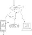
도 1은 관련 기술에 따른 무선 전력 전송 장치로부터 타겟 장치로 전력을 무선 전송하는 동작을 나타낸다.Figure 1 illustrates the operation of wirelessly transmitting power from a wireless power transmission device to a target device in accordance with the related art.
도 1을 참조하면, 본 발명의 일실시예에 따른 무선 전력 전송 장치(110)는 타겟 장치(120)에게 전력을 무선 전송한다. 무선 전력 전송 장치(110)는 전원 공진기(source resonator)(111)를 포함하며, 타겟 장치(120)는 대상 공진기(target resonator)(121)를 포함한다. 무선 전력 전송 장치(110)는 휴대용 단말기에 일 모듈의 형태로 삽입되도록 구현될 수 있다.Referring to FIG. 1, a wireless
이때, 무선 전력 전송 모듈이 타겟 장치(120) 내에 구비되어 있는 경우, 배터리를 독립적으로 무선 충전 하는 것은 불가능하다. 즉, 휴대용 장치에 무선 전 력 전송을 위한 공진기가 구비된 경우, 배터리만을 따로 분리하여 무선 충전할 수 없게 된다. 또한, 배터리와 공진기를 일체화 시키는 경우, 공진기의 특성 변화가 발생할 수 있다. 하기에서는, 배터리 자체만으로도 무선 충전이 가능하고, 특성 변화가 없는 공진기 구조 및 배터리 팩에 대하여 설명하기로 한다.At this time, when the wireless power transmission module is provided in the
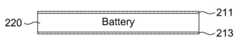
도 2는 본 발명의 일 실시 예에 따른 배터리 팩의 구조를 나타낸다.2 shows a structure of a battery pack according to an embodiment of the present invention.
도 2를 참조하면, 본 발명의 일 실시 예에 따른 배터리 팩은 무선 전력 전송을 위한 박막 형 공진기(210) 및 박막 형 공진기(210)에 의해 생성되는 전력에 의하여 전원을 충전하는 배터리(220)를 포함한다.2, a battery pack according to an embodiment of the present invention includes a
박막 형 공진기(210)는 적층구조로 설계될 수 있다. 즉, 박막 형 공진기(210)는 박막 형태의 제1 전송 선로부(211) 및 박막 형태의 제2 전송 선로부(213)를 포함하여 구성될 수 있다. 이때, 박막 형 공진기(210)는 박막 형태의 제1 전송 선로부(211) 및 박막 형태의 제2 전송 선로부(213) 사이에 유전층(215)을 포함할 수 있다. 이때, 유전층(340)은, 박막 형 공진기의 마그네틱 필드를 증가시키도록 설계될 수 있다. 이때, 유전층(340)은 예를 들어, 강자성체로 구성될 수 있다. 강자성체는, 무선 전력 전송 효율을 증가시키는 효과를 가져올 수 있다.The
도 3 내지 도 4는 본 발명의 일 실시 예에 따른 배터리 팩의 다양한 구현 예들을 나타낸다.3 to 4 show various embodiments of the battery pack according to an embodiment of the present invention.
도 3을 참조하면, 배터리 팩은 제1 전송 선로부(211) 및 배터리(220)로 구 성될 수 있다. 이때, 제1 전송 선로부(211)는 박막 형 공진기로 기능할 수 있다. 도 2의 적층 구조와 구분하기 위하여, 도 3의 제1 전송 선로부(211)를 단일 layer 박막 형 공진기라 칭할 수 있다. 단일 layer 박막 형 공진기에 비하여, 도 2의 적층 구조는 도체 손실이 감소될 수 있다. 즉, 제2 전송 선로부(213)는 강한 커플링이 유도되도록, 제1 전송 선로부(211)에 적층될 수 있고, 도체 손실은 병렬적으로 감소될 수 있다.Referring to FIG. 3, the battery pack may include a first
또한, 도 4를 참조하면, 배터리 팩은 배터리(220)의 상단에 위치하는 제1 전송 선로부(211), 배터리(220)의 하단에 위치하는 제2 전송 선로부(213) 및 배터리(220)로 구성될 수 있다. 도 4와 같이 구성되는 경우, 제1 전송 선로부(211) 및 제2 전송 선로부(213)는 적층 구조의 박막 형 공진기로 기능할 수 있다. 이때, 도 4의 실시 예에서, 제2 전송 선로부(211)는 배터리 팩에 구비되지 않고, 휴대용 단말기 본체에 구비됨으로써, 휴대용 단말기와 배터리 결합 시 도 4의 실시 예와 동일한 구조로 구성될 수도 있다.4, the battery pack includes a first
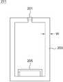
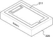
도 5는 제1 전송 선로부(211)의 구성 예를 나타낸다. 또한, 도 7은 도 5의 제1 전송 선로부(211)를 포함하는 배터리 팩의 사시도를 나타낸다.5 shows an example of the configuration of the first
도 5에 도시된 제1 전송 선로부(211)는 도 3에 도시된 단일 layer 박막 형 공진기일 수 있으며, 도 2의 적층 구조에도 적용될 수 있다.The first
제1 전송 선로부(211)는 전송선로(203) 및 커패시터(201)를 포함한다. 또한, 제1 전송 선로부(211)는 피딩부(205)를 더 포함하여 구성될 수 있다. 한편, 제 2 전송 선로부(213)는 제1 전송 선로부(211)와 동일한 구조를 갖거나, 피딩부(205) 및 커패시터(201)가 없는 구조일 수 있다.The first
커패시터(201)는, 제1 전송 선로부(211)의 특정 위치에 삽입된다. 이때, 커패시터(201)는 제1 전송 선로부(211)의 중단에 직렬로 삽입될 수 있다. 이때, 공진기에 생성되는 전계(electric field)는 커패시터(201)에 갇히게 된다.The
커패시터(201)는 집중 소자(lumped element 및 분산 소자(distributed element), 예를 들어 interdigital 커패시터나 높은 유전율을 갖는 기판을 가운데다 둔 gap 커패시터 등의 형태로 제1 전송 선로부(211)에 삽입될 수 있다. 커패시터(201)가 제1 전송 선로부(211)에 삽입됨에 따라, 공진기는 메타물질(metamaterial)의 특성을 가질 수 있다.The
여기서, 메타물질이란 자연에서 발견될 수 없는 특별한 전기적 성질을 갖는 물질로서, 인공적으로 설계된 구조를 갖는다. 자연계에 존재하는 모든 물질들의 전자기 특성은 고유의 유전율 또는 튜자율을 가지며, 대부분의 물질들은 양의 유전율 및 양의 투자율을 갖는다. 대부분의 물질들에서 전계, 자계 및 포인팅 벡터에는 오른손 법칙이 적용되므로, 이러한 물질들을 RHM(Right Handed Material)이라고 한다. 그러나, 메타물질은 1보다 작은 유전율 또는 투자율을 가진 물질로서, 유전율 또는 튜자율의 부호에 따라 ENG(epsilon negative) 물질, MNG(mu negative) 물질, DNG(double negative) 물질, NRI(negative refractive index) 물질, LH(left-handed) 물질 등으로 분류된다.Here, a metamaterial is a material having a special electrical property that can not be found in nature, and has an artificially designed structure. The electromagnetic properties of all materials present in nature have inherent permittivity or tunability, and most materials have a positive permittivity and a positive permeability. In most materials, the right-hand rule applies to electric fields, magnetic fields and pointing vectors, so these materials are called RHM (Right Handed Material). However, the meta-material is a material having a dielectric constant or permeability of less than 1, and may be an ENG (eugilon negative) material, a MNG (mu negative) material, a DNG (double negative) ) Materials, left-handed (LH) materials, and the like.
이 때, 집중 소자로서 삽입된 커패시터(201)의 커패시턴스가 적절히 정해지 는 경우, 상기 공진기는 메타물질의 특성을 가질 수 있다. 특히, 커패시터(201)의 커패시턴스를 적절히 조절함으로써, 공진기는 음의 투자율을 가질 수 있으므로, 본 발명의 일실시예에 따른 공진기는 박막 형 MNG 공진기로 불려질 수 있다.At this time, when the capacitance of the
상기 박막 형 MNG 공진기는 전파 상수(propagation constant)가 0일 때의 주파수를 공진 주파수로 갖는 영번째 공진(Zeroth-Order Resonance) 특성을 가질 수 있다. 박막 형 MNG 공진기는 영번째 공진 특성을 가질 수 있으므로, 공진 주파수는 박막 형 MNG 공진기의 물리적인 사이즈에 대해 독립적일 수 있다. 즉, 박막 형 MNG 공진기에서 공진 주파수를 변경하기 위해서는 커패시터를 적절히 설계하는 것으로 충분하므로, 박막 형 MNG 공진기의 물리적인 사이즈를 변경하지 않을 수 있다.The thin film type MNG resonator may have a zeroth-order resonance characteristic having a resonance frequency at a frequency when the propagation constant is zero. Since the thin film MNG resonator can have zero resonance characteristics, the resonant frequency can be independent of the physical size of the thin film MNG resonator. That is, it is sufficient to appropriately design a capacitor to change the resonant frequency in the thin film type MNG resonator, so that the physical size of the thin film type MNG resonator can be changed.
또한, 근접 필드(near field)에서 전계는 제1 전송 선로부(211)에 삽입된 직렬 커패시터(201)에 집중되므로, 직렬 커패시터(201)로 인하여 근접 필드에서는 자계(magnetic field)가 도미넌트(dominant)해진다.Since the electric field in the near field is concentrated in the
또한, MNG 공진기는 집중 소자로의 커패시터(201)를 이용하여 높은 큐-팩터(Q-Factor)를 가질 수 있으므로, 전력 전송의 효율을 향상시킬 수 있다.In addition, since the MNG resonator can have a high Q-factor by using the
피딩부(205)는 제1 전송 선로부(211)에 전류를 공급하는 마이크로 스트립(Micro-strip) 라인으로 구성될 수 있다. 이에 따라, 본 발명의 일 실시 예에 따른 박막 형 공진기는 임피던스 매칭을 위한 별도의 매칭 수단이 필요 없는 구조를 갖는다.The
도 6은 본 발명의 다른 실시예에 따른 배터리 팩의 구조를 나타낸다.6 shows a structure of a battery pack according to another embodiment of the present invention.
도 6을 참조하면, 본 발명의 다른 실시예에 따른 배터리 팩은, 박막 형 공진기(211, 213) 및 상기 배터리 사이에 높은 임피던스 표면(HIS, High Impedance Suffice)(630)을 포함한다. 이때, 높은 임피던스 표면(630)은, 박막 형 공진기(211, 213)와 배터리(220) 사이의 마그네틱 필드에 의해 유도되는 표면 전류(surface current) 를 차단하고, 간섭(Interference)을 제거함으로써, 공진기의 특성 변화를 방지할 수 있다. 이때, 높은 임피던스 표면(630)은 배터리에 부착하기 위한, 박막 형태로 설계될 수 있다.Referring to FIG. 6, a battery pack according to another embodiment of the present invention includes thin
한편, 도 2 내지 도 6에 명시적으로 도시하지는 않았지만, 박막형 공진기(210), 제1 전송 선로부(211) 및 제2 전송 선로부(213)는, 배터리(220)에 접착되기 위한 접착층을 더 포함할 수 있다.2 to 6, the
도 8 및 도 9는 본 발명의 본 발명의 또 다른 실시 예에 따른 배터리 팩의 구조를 나타낸다. 이때, 도 8은 배터리 팩의 평면도이고, 도 9는 측면도를 나타낸다.8 and 9 show a structure of a battery pack according to another embodiment of the present invention. 8 is a plan view of the battery pack, and Fig. 9 is a side view.
도 8 및 도 9를 참조하면, 본 발명의 또 다른 실시 예에 따른 배터리 팩은, 3-D 형태의 공진기(8210), 충전 제어부(221), 배터리(220) 및 차단부(810)를 포함한다.8 and 9, a battery pack according to another embodiment of the present invention includes a 3-D resonator 8210, a
이때, 3-D형태의 공진기(820)는, 예를 들어, 복수의 박막형 공진기를 병렬 로 배치함으로써 구성될 수 있다. 복수의 박막형 공진기를 병렬로 배치하면, 3-D형태의 공진기(820)의 전송 효율 및 전송 거리를 증가 시킬 수 있다.At this time, the 3-
충전 제어부(221)는 일반적인 배터리 팩에 구비되는 충전회로일 수 있다.The
한편, 차단부(810)는 HIS 또는 Shielding제로 구성될 수 있다. 따라서, 차단부(810)는 높은 임피던스 표면(HIS, High Impedance Suffice) 특성을 가질 수 있다. 또한, 차단부(810)는 3-D형태의 공진기(820)와 배터리(220) 사이의 마그네틱 필드에 의해 유도되는 표면 전류(surface current) 를 차단하고, 간섭(Interference)을 제거할 수 있다.On the other hand, the blocking
이상과 같이 본 발명은 비록 한정된 실시예와 도면에 의해 설명되었으나, 본 발명은 상기의 실시예에 한정되는 것은 아니며, 본 발명이 속하는 분야에서 통상의 지식을 가진 자라면 이러한 기재로부터 다양한 수정 및 변형이 가능하다.While the invention has been shown and described with reference to certain preferred embodiments thereof, it will be understood by those of ordinary skill in the art that various changes in form and details may be made therein without departing from the spirit and scope of the invention as defined by the appended claims. This is possible.
그러므로, 본 발명의 범위는 설명된 실시예에 국한되어 정해져서는 아니 되며, 후술하는 특허청구범위뿐 아니라 이 특허청구범위와 균등한 것들에 의해 정해져야 한다.Therefore, the scope of the present invention should not be limited to the described embodiments, but should be determined by the equivalents of the claims, as well as the claims.
도 1은 관련 기술에 따른 무선 전력 전송 장치로부터 타겟 장치로 전력을 무선 전송하는 동작을 나타낸다.Figure 1 illustrates the operation of wirelessly transmitting power from a wireless power transmission device to a target device in accordance with the related art.
도 2는 본 발명의 일 실시 예에 따른 배터리 팩의 구조를 나타낸다.2 shows a structure of a battery pack according to an embodiment of the present invention.
도 3 내지 도 4는 본 발명의 일 실시 예에 따른 배터리 팩의 다양한 구현 예들을 나타낸다.3 to 4 show various embodiments of the battery pack according to an embodiment of the present invention.
도 5는 제1 전송 선로부의 구성 예를 나타낸다.5 shows a configuration example of the first transmission line section.
도 6은 본 발명의 다른 실시예에 따른 배터리 팩의 구조를 나타낸다.6 shows a structure of a battery pack according to another embodiment of the present invention.
도 7은 도 5의 제1 전송 선로부를 포함하는 배터리 팩의 사시도를 나타낸다.FIG. 7 is a perspective view of a battery pack including the first transmission line portion of FIG. 5;
도 8 및 도 9는 본 발명의 본 발명의 또 다른 실시 예에 따른 배터리 팩의 구조를 나타낸다.8 and 9 show a structure of a battery pack according to another embodiment of the present invention.
Claims (12)
Translated fromKoreanPriority Applications (2)
| Application Number | Priority Date | Filing Date | Title |
|---|---|---|---|
| KR1020090124269AKR101730139B1 (en) | 2009-12-14 | 2009-12-14 | Battery pack with wireless power transmission resonator |
| US12/967,159US8957629B2 (en) | 2009-12-14 | 2010-12-14 | Battery pack with wireless power transmission resonator |
Applications Claiming Priority (1)
| Application Number | Priority Date | Filing Date | Title |
|---|---|---|---|
| KR1020090124269AKR101730139B1 (en) | 2009-12-14 | 2009-12-14 | Battery pack with wireless power transmission resonator |
Publications (2)
| Publication Number | Publication Date |
|---|---|
| KR20110067610A KR20110067610A (en) | 2011-06-22 |
| KR101730139B1true KR101730139B1 (en) | 2017-05-11 |
Family
ID=44142130
Family Applications (1)
| Application Number | Title | Priority Date | Filing Date |
|---|---|---|---|
| KR1020090124269AExpired - Fee RelatedKR101730139B1 (en) | 2009-12-14 | 2009-12-14 | Battery pack with wireless power transmission resonator |
Country Status (2)
| Country | Link |
|---|---|
| US (1) | US8957629B2 (en) |
| KR (1) | KR101730139B1 (en) |
Families Citing this family (16)
| Publication number | Priority date | Publication date | Assignee | Title |
|---|---|---|---|---|
| WO2011005012A2 (en)* | 2009-07-06 | 2011-01-13 | 삼성전자주식회사 | Wireless power transmission system and resonator for the system |
| KR101364992B1 (en)* | 2011-01-28 | 2014-02-20 | 삼성전자주식회사 | Apparatus and method for wireless power transmission |
| KR102028057B1 (en) | 2013-01-22 | 2019-10-04 | 삼성전자주식회사 | Resonator with improved isolation |
| US9716401B2 (en) | 2014-01-06 | 2017-07-25 | Otter Products, Llc | Recharegable battery pack |
| US9635222B2 (en) | 2014-08-03 | 2017-04-25 | PogoTec, Inc. | Wearable camera systems and apparatus for aligning an eyewear camera |
| CA2956795C (en) | 2014-08-03 | 2020-06-30 | PogoTec, Inc. | Wearable camera systems and apparatus and method for attaching camera systems or other electronic devices to wearable articles |
| CA2972064A1 (en) | 2014-12-23 | 2016-06-30 | PogoTec, Inc. | Wireless camera system and methods |
| EP3308216B1 (en) | 2015-06-10 | 2021-04-21 | Pogotec, Inc. | Eyewear with magnetic track for electronic wearable device |
| US10481417B2 (en) | 2015-06-10 | 2019-11-19 | PogoTec, Inc. | Magnetic attachment mechanism for electronic wearable device |
| TW201729610A (en) | 2015-10-29 | 2017-08-16 | 帕戈技術股份有限公司 | Hearing aid adapted for wireless power reception |
| US11558538B2 (en) | 2016-03-18 | 2023-01-17 | Opkix, Inc. | Portable camera system |
| GB201611532D0 (en)* | 2016-07-01 | 2016-08-17 | Dukosi Ltd | Electric batteries |
| EP3539285A4 (en) | 2016-11-08 | 2020-09-02 | Pogotec, Inc. | A smart case for electronic wearable device |
| US10282105B2 (en)* | 2017-01-20 | 2019-05-07 | International Business Machines Corporation | Extending shelf life of non-volatile memory devices |
| US11300857B2 (en) | 2018-11-13 | 2022-04-12 | Opkix, Inc. | Wearable mounts for portable camera |
| US11831033B2 (en) | 2020-01-09 | 2023-11-28 | Otter Products, Llc | Hot-swappable battery pack system |
Citations (1)
| Publication number | Priority date | Publication date | Assignee | Title |
|---|---|---|---|---|
| US20090140946A1 (en)* | 2007-10-31 | 2009-06-04 | Ziolkowski Richard W | Efficient metamaterial-inspired electrically-small antenna |
Family Cites Families (22)
| Publication number | Priority date | Publication date | Assignee | Title |
|---|---|---|---|---|
| US6690251B2 (en)* | 2001-04-11 | 2004-02-10 | Kyocera Wireless Corporation | Tunable ferro-electric filter |
| KR100981524B1 (en)* | 2001-12-20 | 2010-09-10 | 엔엑스피 비 브이 | Couplers, integrated electronics and electronic devices and methods of using the same |
| US6727785B2 (en)* | 2002-06-27 | 2004-04-27 | Harris Corporation | High efficiency single port resonant line |
| US6933812B2 (en)* | 2002-10-10 | 2005-08-23 | The Regents Of The University Of Michigan | Electro-ferromagnetic, tunable electromagnetic band-gap, and bi-anisotropic composite media using wire configurations |
| US6938325B2 (en)* | 2003-01-31 | 2005-09-06 | The Boeing Company | Methods of fabricating electromagnetic meta-materials |
| US7218190B2 (en) | 2003-06-02 | 2007-05-15 | The Trustees Of The University Of Pennsylvania | Waveguides and scattering devices incorporating epsilon-negative and/or mu-negative slabs |
| US7109944B2 (en)* | 2004-01-26 | 2006-09-19 | Kyocera Corporation | Antenna using variable capacitance element and wireless communication apparatus using the same |
| US7307596B1 (en)* | 2004-07-15 | 2007-12-11 | Rockwell Collins, Inc. | Low-cost one-dimensional electromagnetic band gap waveguide phase shifter based ESA horn antenna |
| KR100543779B1 (en) | 2004-07-21 | 2006-01-23 | 주식회사 한림포스텍 | Portable terminal with built-in battery pack and built-in battery pack with radio frequency identification technology |
| JP3928055B2 (en)* | 2005-03-02 | 2007-06-13 | 国立大学法人山口大学 | Negative permeability or negative permittivity metamaterial and surface wave waveguide |
| KR100603986B1 (en) | 2005-03-07 | 2006-07-25 | 주식회사 한림포스텍 | Battery pack for wireless charge |
| US8232764B2 (en)* | 2006-03-24 | 2012-07-31 | Kabushiki Kaisha Toshiba | Power receiving device, and electronic apparatus and non-contact charging system using the same |
| KR100859445B1 (en) | 2006-12-11 | 2008-09-22 | 주식회사 한림포스텍 | Portable terminal with a contactless rechargeable battery pack and a contactless battery pack |
| US8115448B2 (en)* | 2007-06-01 | 2012-02-14 | Michael Sasha John | Systems and methods for wireless power |
| KR100819753B1 (en) | 2007-07-13 | 2008-04-08 | 주식회사 한림포스텍 | Contactless charging system for battery pack solution and its control method |
| KR101425678B1 (en) | 2007-09-12 | 2014-07-31 | 엘지전자 주식회사 | Solid-state charging system |
| US7456606B1 (en)* | 2008-04-23 | 2008-11-25 | International Business Machines Corporation | Battery label with wireless battery charging circuit |
| KR101094253B1 (en) | 2008-04-28 | 2011-12-19 | 정춘길 | Non-contact power receier, non-contact power trasmitter related to the same and non-contact power transmitting and receiving system |
| US8947041B2 (en)* | 2008-09-02 | 2015-02-03 | Qualcomm Incorporated | Bidirectional wireless power transmission |
| US8174341B2 (en)* | 2008-12-01 | 2012-05-08 | Toyota Motor Engineering & Manufacturing North America, Inc. | Thin film based split resonator tunable metamaterial |
| US8796999B2 (en)* | 2009-02-12 | 2014-08-05 | Qualcomm Incorporated | Wireless power transfer for low power devices |
| US20110057606A1 (en)* | 2009-09-04 | 2011-03-10 | Nokia Corpation | Safety feature for wireless charger |
- 2009
- 2009-12-14KRKR1020090124269Apatent/KR101730139B1/ennot_activeExpired - Fee Related
- 2010
- 2010-12-14USUS12/967,159patent/US8957629B2/enactiveActive
Patent Citations (1)
| Publication number | Priority date | Publication date | Assignee | Title |
|---|---|---|---|---|
| US20090140946A1 (en)* | 2007-10-31 | 2009-06-04 | Ziolkowski Richard W | Efficient metamaterial-inspired electrically-small antenna |
Also Published As
| Publication number | Publication date |
|---|---|
| US8957629B2 (en) | 2015-02-17 |
| KR20110067610A (en) | 2011-06-22 |
| US20110140541A1 (en) | 2011-06-16 |
Similar Documents
| Publication | Publication Date | Title |
|---|---|---|
| KR101730139B1 (en) | Battery pack with wireless power transmission resonator | |
| US11264837B2 (en) | Transmitting base with antenna having magnetic shielding panes | |
| CN108140950B (en) | Antenna unit and wireless power transmission module comprising same | |
| JP5944886B2 (en) | Wireless charging set and its source part | |
| US9496082B2 (en) | Coil substrate for wireless charging and electric device using the same | |
| KR101718723B1 (en) | Laptop computer system with wireless power transform function | |
| CN111527666B (en) | wireless power transmission device | |
| EP2852028A1 (en) | Antenna sheet for contactless charging device and charging device using said sheet | |
| KR20100055069A (en) | Apparatus of wireless power transmission using high q near magnetic field resonator | |
| KR20120019578A (en) | Wireless power transmission apparatus and method for transmitting resonance power in multiple bands | |
| KR101644908B1 (en) | Mimo antenna apparatus | |
| US20140218246A1 (en) | Antenna device and communication terminal apparatus | |
| KR20110109703A (en) | Wireless power receiver with shielding film | |
| KR101350792B1 (en) | High efficiency resontor in wireless power transmission system | |
| KR101378550B1 (en) | Thin film type resontor in wireless power transmission system | |
| Wu et al. | Wireless power transfer with artificial magnetic conductors | |
| CN104685761A (en) | Wireless power transmission device and its power supply control method | |
| KR20110116026A (en) | Antenna device for high speed data transmission and wireless energy transmission | |
| Rahayu et al. | Radiator for wireless charging application based on electromagnetic coupling resonant | |
| KR101629811B1 (en) | Wireless energy transmitting system | |
| Senior et al. | Planar wireless power tranfer system with embedded magnetic metamaterial resonators | |
| KR20230020382A (en) | High Inherent Quality Receiver Construction | |
| Vital | A Novel Array of Strongly Coupled Magnetic Resonators for Misalignment-Resilient Wireless Power Transfer, Harvesting, and Sensing in Wearable Applications |
Legal Events
| Date | Code | Title | Description |
|---|---|---|---|
| PA0109 | Patent application | St.27 status event code:A-0-1-A10-A12-nap-PA0109 | |
| PG1501 | Laying open of application | St.27 status event code:A-1-1-Q10-Q12-nap-PG1501 | |
| R18-X000 | Changes to party contact information recorded | St.27 status event code:A-3-3-R10-R18-oth-X000 | |
| A201 | Request for examination | ||
| PA0201 | Request for examination | St.27 status event code:A-1-2-D10-D11-exm-PA0201 | |
| D13-X000 | Search requested | St.27 status event code:A-1-2-D10-D13-srh-X000 | |
| P22-X000 | Classification modified | St.27 status event code:A-2-2-P10-P22-nap-X000 | |
| D14-X000 | Search report completed | St.27 status event code:A-1-2-D10-D14-srh-X000 | |
| E902 | Notification of reason for refusal | ||
| PE0902 | Notice of grounds for rejection | St.27 status event code:A-1-2-D10-D21-exm-PE0902 | |
| E13-X000 | Pre-grant limitation requested | St.27 status event code:A-2-3-E10-E13-lim-X000 | |
| P11-X000 | Amendment of application requested | St.27 status event code:A-2-2-P10-P11-nap-X000 | |
| P13-X000 | Application amended | St.27 status event code:A-2-2-P10-P13-nap-X000 | |
| E701 | Decision to grant or registration of patent right | ||
| PE0701 | Decision of registration | St.27 status event code:A-1-2-D10-D22-exm-PE0701 | |
| GRNT | Written decision to grant | ||
| PR0701 | Registration of establishment | St.27 status event code:A-2-4-F10-F11-exm-PR0701 | |
| PR1002 | Payment of registration fee | St.27 status event code:A-2-2-U10-U11-oth-PR1002 Fee payment year number:1 | |
| PG1601 | Publication of registration | St.27 status event code:A-4-4-Q10-Q13-nap-PG1601 | |
| P22-X000 | Classification modified | St.27 status event code:A-4-4-P10-P22-nap-X000 | |
| PR1001 | Payment of annual fee | St.27 status event code:A-4-4-U10-U11-oth-PR1001 Fee payment year number:4 | |
| P22-X000 | Classification modified | St.27 status event code:A-4-4-P10-P22-nap-X000 | |
| P22-X000 | Classification modified | St.27 status event code:A-4-4-P10-P22-nap-X000 | |
| PC1903 | Unpaid annual fee | St.27 status event code:A-4-4-U10-U13-oth-PC1903 Not in force date:20210420 Payment event data comment text:Termination Category : DEFAULT_OF_REGISTRATION_FEE | |
| P22-X000 | Classification modified | St.27 status event code:A-4-4-P10-P22-nap-X000 | |
| PC1903 | Unpaid annual fee | St.27 status event code:N-4-6-H10-H13-oth-PC1903 Ip right cessation event data comment text:Termination Category : DEFAULT_OF_REGISTRATION_FEE Not in force date:20210420 |