KR101729488B1 - Spacer automatic assembly device of form removal deck - Google Patents
Spacer automatic assembly device of form removal deckDownload PDFInfo
- Publication number
- KR101729488B1 KR101729488B1KR1020150082169AKR20150082169AKR101729488B1KR 101729488 B1KR101729488 B1KR 101729488B1KR 1020150082169 AKR1020150082169 AKR 1020150082169AKR 20150082169 AKR20150082169 AKR 20150082169AKR 101729488 B1KR101729488 B1KR 101729488B1
- Authority
- KR
- South Korea
- Prior art keywords
- deck
- piercing
- bolt
- cylinder
- press
- Prior art date
- Legal status (The legal status is an assumption and is not a legal conclusion. Google has not performed a legal analysis and makes no representation as to the accuracy of the status listed.)
- Active
Links
- 125000006850spacer groupChemical group0.000titleclaimsabstractdescription34
- 238000000465mouldingMethods0.000claimsabstractdescription12
- 238000000034methodMethods0.000claimsdescription19
- 238000003780insertionMethods0.000claimsdescription10
- 230000037431insertionEffects0.000claimsdescription10
- NJPPVKZQTLUDBO-UHFFFAOYSA-NnovaluronChemical compoundC1=C(Cl)C(OC(F)(F)C(OC(F)(F)F)F)=CC=C1NC(=O)NC(=O)C1=C(F)C=CC=C1FNJPPVKZQTLUDBO-UHFFFAOYSA-N0.000claimsdescription9
- 239000002184metalSubstances0.000claimsdescription3
- 239000000463materialSubstances0.000abstractdescription8
- 230000003252repetitive effectEffects0.000abstract1
- 230000008569processEffects0.000description9
- 229910000831SteelInorganic materials0.000description6
- 239000010959steelSubstances0.000description6
- 230000008901benefitEffects0.000description3
- 238000009434installationMethods0.000description3
- 230000032258transportEffects0.000description3
- 238000010276constructionMethods0.000description2
- 230000007547defectEffects0.000description2
- 238000003754machiningMethods0.000description2
- 238000012986modificationMethods0.000description2
- 230000004048modificationEffects0.000description2
- 230000003014reinforcing effectEffects0.000description2
- 230000008878couplingEffects0.000description1
- 238000010168coupling processMethods0.000description1
- 238000005859coupling reactionMethods0.000description1
- 230000003028elevating effectEffects0.000description1
- 238000009415formworkMethods0.000description1
- 230000009467reductionEffects0.000description1
- 238000000926separation methodMethods0.000description1
- 238000004904shorteningMethods0.000description1
- XLYOFNOQVPJJNP-UHFFFAOYSA-NwaterSubstancesOXLYOFNOQVPJJNP-UHFFFAOYSA-N0.000description1
- 238000003466weldingMethods0.000description1
Images


Classifications
- E—FIXED CONSTRUCTIONS
- E04—BUILDING
- E04G—SCAFFOLDING; FORMS; SHUTTERING; BUILDING IMPLEMENTS OR AIDS, OR THEIR USE; HANDLING BUILDING MATERIALS ON THE SITE; REPAIRING, BREAKING-UP OR OTHER WORK ON EXISTING BUILDINGS
- E04G21/00—Preparing, conveying, or working-up building materials or building elements in situ; Other devices or measures for constructional work
- E04G21/12—Mounting of reinforcing inserts; Prestressing
- E04G21/122—Machines for joining reinforcing bars
- E—FIXED CONSTRUCTIONS
- E04—BUILDING
- E04B—GENERAL BUILDING CONSTRUCTIONS; WALLS, e.g. PARTITIONS; ROOFS; FLOORS; CEILINGS; INSULATION OR OTHER PROTECTION OF BUILDINGS
- E04B5/00—Floors; Floor construction with regard to insulation; Connections specially adapted therefor
- E04B5/16—Load-carrying floor structures wholly or partly cast or similarly formed in situ
- E04B5/32—Floor structures wholly cast in situ with or without form units or reinforcements
- E04B5/36—Floor structures wholly cast in situ with or without form units or reinforcements with form units as part of the floor
- E04B5/38—Floor structures wholly cast in situ with or without form units or reinforcements with form units as part of the floor with slab-shaped form units acting simultaneously as reinforcement; Form slabs with reinforcements extending laterally outside the element
- E04B5/40—Floor structures wholly cast in situ with or without form units or reinforcements with form units as part of the floor with slab-shaped form units acting simultaneously as reinforcement; Form slabs with reinforcements extending laterally outside the element with metal form-slabs
- E—FIXED CONSTRUCTIONS
- E04—BUILDING
- E04C—STRUCTURAL ELEMENTS; BUILDING MATERIALS
- E04C5/00—Reinforcing elements, e.g. for concrete; Auxiliary elements therefor
- E04C5/16—Auxiliary parts for reinforcements, e.g. connectors, spacers, stirrups
- E04C5/168—Spacers connecting parts for reinforcements and spacing the reinforcements from the form
- E—FIXED CONSTRUCTIONS
- E04—BUILDING
- E04C—STRUCTURAL ELEMENTS; BUILDING MATERIALS
- E04C5/00—Reinforcing elements, e.g. for concrete; Auxiliary elements therefor
- E04C5/16—Auxiliary parts for reinforcements, e.g. connectors, spacers, stirrups
- E04C5/18—Spacers of metal or substantially of metal
- E—FIXED CONSTRUCTIONS
- E04—BUILDING
- E04G—SCAFFOLDING; FORMS; SHUTTERING; BUILDING IMPLEMENTS OR AIDS, OR THEIR USE; HANDLING BUILDING MATERIALS ON THE SITE; REPAIRING, BREAKING-UP OR OTHER WORK ON EXISTING BUILDINGS
- E04G21/00—Preparing, conveying, or working-up building materials or building elements in situ; Other devices or measures for constructional work
- E04G21/14—Conveying or assembling building elements
- E04G21/16—Tools or apparatus
Landscapes
- Engineering & Computer Science (AREA)
- Architecture (AREA)
- Civil Engineering (AREA)
- Structural Engineering (AREA)
- Mechanical Engineering (AREA)
- Physics & Mathematics (AREA)
- Electromagnetism (AREA)
- Automatic Assembly (AREA)
Abstract
Translated fromKorean
Description
Translated fromKorean본 발명은 탈형 데크에 다수의 간격재를 설치하기 위한 장치에 관한 것으로, 특히 탈형 데크에 피어싱 홀을 정렬되게 가공하고, 그 가공된 홀에 간격재를 일대일 대응되게 위치시킨 후 볼트를 정위치에서 자동 체결시킬 수 있도록 한 탈형 데크의 간격재 자동 조립 장치에 관한 것이다.The present invention relates to an apparatus for installing a plurality of spacers on a deformation-type deck, and more particularly to an apparatus for aligning a plurality of spacers on a deformation-type deck, To a device for automatic re-assembly of a de-molding deck to be automatically engaged.
기존의 일체형 데크의 경우 비용 절감, 공사기간 단축 등 여러 장점에도 불구하고 하부 강판과 상부의 철근 구조체(트러스거더)가 용접으로 고정된 탓에 건축물에 물이 새거나 균열이 생겼을 때 이를 확인할 방법이 없어 기술적 한계로 남아 있다.In the case of the existing integrated deck, there is no way to confirm water leaks or cracks in the building due to the fact that the lower steel plate and the upper reinforcing structure (truss girder) are fixed by welding in spite of various advantages such as cost reduction and construction period shortening. It remains a technical limitation.
하지만 탈형 데크는 강판을 자유롭게 분리할 수 있기 때문에 이 같은 단점을 보완할 수 있다. 탈형 데크는 하부 강판의 분리가 가능해 시공 후 유지 보수가 쉽고 분리된 강판을 재활용할 수 있다. 이러한 탈형 데크를 콘크리트 슬래브의 시공시 적용하기 위해서는 타설된 콘크리트에 충분히 저항할 수 있는 강성을 가져야 한다. 탈형 데크에서 거푸집널의 탈형을 용이하게 하고 트러스의 설치를 용이하게 하기 위해 간격재를 사용하고 있다.However, the decking deck can compensate for these disadvantages by allowing the steel plate to be separated freely. The decking deck allows for the separation of the lower steel plate, which makes it easy to maintain after construction and recycles the separated steel plate. In order to apply the deformation-type deck to the concrete slab, it is required to have a rigidity sufficient to resist the poured concrete. A spacing material is used to facilitate the demolding of the formwork in the decking deck and to facilitate the installation of the truss.
탈형 데크에서 간격재는 다수열로 일정 간격마다 정렬되어져 설치되어지며, 하나의 간격재는 2개소에서 체결볼트가 체결되어 조립된다. 이 경우 하나의 탈형 데크에는 수십군데 이상의 체결홀을 형성해야 하고, 또 그 체결홀에 일일히 볼트를 체결해야 하는 번거롭고 시간이 많이 걸리는 체결 작업이 이루어져야 하므로 생산성이 저하되는 문제가 발생한다.In the deformation type deck, the spacers are arranged in a plurality of rows at regular intervals, and one spacer is assembled by fastening the fastening bolts at two places. In this case, it is necessary to form dozens of fastening holes in one deformation-type deck, and a troublesome and time-consuming fastening operation to fasten the bolts to the fastening holes must be performed.
한편, 본 발명의 배경이 되는 기술로는 한국 등록특허 등록번호 제10-1237323호에 탈형 데크용 스페이서가 제안되어 있다. 이는 스페이서 몸체의 하부에 상부를 향하는 암나사가 형성되어지고, 스페이서헤드는 헤드편이 하부에서 상부를 향하여 좁아지게 절곡되어 길이방향으로 형성되어지고, 헤드편의 하단에 외측 상부로 보강편이 경사지게 절곡되어지게 구성하고 있다.Meanwhile, as a background of the present invention, a spacer for de-molding decks has been proposed in Korean Patent Registration No. 10-1237323. The spacer head is formed in a longitudinal direction by being bent so as to be narrowed from the lower part to the upper part, and the reinforcing part is bent at an upper part on the lower side of the head part in an inclined manner. .
이 전자의 배경기술은 슬래브 하부로 스페이서몸체에 형성된 암나사가 노출되는 작업이 용이하게 이루어질 수 있도록 하는 가운데 노출된 주변을 깨끗하게 할 수 있도록 하고, 아울러 충분한 지지력 내지는 매립력이 확보되어지는 장점을 갖는다. 그러나 상기 전자의 배경기술은 강판에 스페이서몸체를 자동으로 조립할 수 있는 방법이 제안되어 있지 않다. 따라서 스페이서몸체를 강판에 체결하는데 많은 작업 시간이 소요되어 생산성을 높이는데 한계가 있다.The background art of the former has an advantage that a work for exposing the female screw formed on the spacer body to the lower portion of the slab can be easily performed, and the exposed periphery can be cleaned, and sufficient supporting force or filling power is secured. However, the background art of the former does not propose a method of automatically assembling the spacer body on the steel plate. Therefore, it takes a lot of time to fasten the spacer body to the steel plate, which limits the productivity.
다른 한편, 한국 등록특허 등록번호 제10-1503015호로서, 볼트 자동 조립 장치가 제안되어 있다. 이는 한쪽 끝에 볼트의 고정이 가능한 스핀들이 설치되고 그리고 볼트의 토크의 측정이 가능한 토크 센서 유닛을 가진 스핀들 모듈; 스핀들 모듈의 이동을 위한 슬라이딩 모듈; 및 가공물의 고정을 위한 클램프 및 클램프의 상하 이동을 위한 적어도 하나의 실린더 유닛을 가진 지그 모듈을 포함한다.On the other hand, Korean Patent Registration No. 10-1503015 proposes a bolt automatic assembling apparatus. A spindle module having a torque sensor unit with a spindle capable of fixing a bolt at one end and capable of measuring the torque of the bolt; A sliding module for moving the spindle module; And a jig module having a clamp for fixing the workpiece and at least one cylinder unit for moving the clamp up and down.
이 후자의 배경기술은 가공물에 형성된 볼트 홀 또는 핀 홀에 볼트가 연속적으로 결합이 될 수 있도록 하면서 조립되는 볼트 또는 핀에 대한 토크를 탐지하는 것에 의하여 조립 품질의 균일성의 확보될 수 있도록 하는 장점을 갖는다.This latter technique has the advantage of ensuring the uniformity of the assembly quality by detecting the torque on the bolt or pin being assembled while allowing the bolt to be continuously connected to the bolt hole or pin hole formed in the workpiece .
그러나 후자의 배경기술을 데크에 설치되는 간격재의 조립에 적용되는 경우 간격재를 볼트 조립 위치로 연속적으로 정위치시키는 방법과, 볼트가 조립되는 홀을 정렬 위치에서 가공하는 방법이 제안되어 있지 않아 탈형 데크의 간격재 조립 장치에 적용할 수 없는 단점이 있다.However, when the latter background technique is applied to the assembly of the spacers provided in the deck, there is no proposal of a method of continuously positioning the spacers to the bolt assembly position and a method of machining the holes in which the bolts are assembled at the alignment positions, There is a disadvantage that it can not be applied to a de-interspace reassembling apparatus.
본 발명은 탈형 데크에 피어싱 홀을 정렬되게 가공하고, 그 가공된 홀에 간격재를 일대일 대응되게 위치시킨 후 볼트를 정위치에서 자동 체결시킬 수 있도록 한 탈형 데크의 간격재 자동 조립 장치를 제공함에 그 목적이 있다.The present invention provides a device for automatic assembly of spacers on de-molding decks in which a piercing hole is aligned on a de-molding deck, a bolt is automatically engaged in a predetermined position after locating spacing members in a corresponding one- It has its purpose.
본 발명의 적절한 실시 형태에 따른 탈형 데크의 간격재 자동 조립 장치는,According to a preferred embodiment of the present invention,
일정폭과 길이를 갖는 데크를 피어싱 위치까지 이송시키기 위한 데크 이송컨베어와;A deck conveying conveyor for conveying a deck having a predetermined width and length to a piercing position;
데크의 이송라인 하부에 배치되어 간격재를 볼트 조립위치로 이송시키는 간격재 이송컨베어와;An interval re-conveying conveyor disposed below the conveying line of the deck for conveying the spacing member to the bolt assembling position;
상기 데크에 복수개의 피어싱 홀을 피어싱 상,하 금형을 통해 형성시킨 후 볼트 조립위치까지 데크를 이송시킨 후 다시 피어싱 위치로 피어싱 상,하 금형을 복귀시키는 반복동작을 하는 피어싱 프레스유닛과;A piercing press unit for repeating operations of forming a plurality of piercing holes through the piercing upper and lower dies on the deck, conveying the deck to the bolt assembling position, and then returning the pierced upper and lower dies to the piercing position;
상기 피어싱 프레스 유닛의 피어싱 가공 및 볼트 조립되는 동안 데크를 클램핑하고, 데크의 배출 방향 이송시 데크를 클램핑 해제시키는 한 쌍의 데크 클램핑유닛과;A pair of deck clamping units for clamping the deck during piercing and bolt assembly of the piercing press unit and for clamping decks during delivery of the deck in the discharge direction;
상기 피어싱 상,하 금형의 피어싱 위치로 복귀 완료시 상기 간격재 이송컨베어에 안착된 간격재를 상승시켜 데크의 하면에서 피어싱 홀에 밀착되게 위치시킨 후 볼트 체결 후 원위치로 복귀하는 간격재 자동공급유닛과;And an interval automatic material feeding unit for returning to the original position after the bolt is tightened after the spacing member seated on the interval re-conveying conveyor is raised so as to be brought into close contact with the piercing hole at the lower face of the deck when the piercing and lower die piercing positions are completed, and;
상기 피어싱 프레스유닛이 피어싱 위치로 복귀 완료시 데크의 상면에서 피어싱 홀을 통해 볼트를 체결하여 간격재를 데크에 결합시킨 후 원위치로 복귀하는 볼트 조립유닛; 및A bolt assembling unit for fastening the bolt through the piercing hole on the upper surface of the deck when the piercing press unit returns to the piercing position to join the spacer to the deck and returning to the original position; And
간격재가 체결된 데크를 반출해내는 데크 반출컨베어를 포함하여 구성된 것을 특징으로 한다.And a deck carrying conveyor for taking out the deck fastened with the spacer material.
또한, 상기 피어싱 프레스유닛은,In addition, the piercing press unit includes:
프레스 프레임과;A press frame;
상기 프레스 프레임의 상면에 슬라이딩 지지되어 피어싱 위치와 볼트 조립위치를 왕복하는 프레스 헤드와;A press head slidably supported on an upper surface of the press frame to reciprocate between a piercing position and a bolt assembly position;
상기 프레스 헤드에 수직 방향으로 입설되어 있는 피어싱 실린더와;A piercing cylinder extending perpendicularly to the press head;
상기 프레스 헤드의 하측에 고정 설치된 피어싱 하금형과;A piercing die fixed to a lower side of the press head;
상기 피어싱 하금형의 상방에 배치되어 상기 피어싱 실린더에 의해 하강 작동하여 상기 데크에 피어싱 홀을 형성시키는 피어싱 상금형과;A piercing upper die disposed above the piercing die for lowering operation by the piercing cylinder to form a piercing hole in the deck;
상기 프레스 프레임에 회전 가능하게 지지되어 상기 프레스 헤드와 스크류 결합되어 있는 프레스 이송스크류와;A press conveying screw rotatably supported on the press frame and screwed to the press head;
상기 프레스 프레임에 장착되어 상기 프레스 이송스크류를 정역회전 구동시키는 프레스 이송모터를 포함하여 구성된 것을 특징으로 한다.And a press feed motor mounted on the press frame for normally and rotatably driving the press feed screw.
또한, 상기 프레스 헤드측에는 데크의 피어싱 위치를 결정하기 위한 스톱퍼 유닛이 설치되고;Further, on the press head side, a stopper unit for determining the piercing position of the deck is installed;
상기 스톱퍼 유닛은,Wherein the stopper unit comprises:
상기 프레스 헤드의 하면에 고정되어 선단에 돌출 고정된 스톱퍼 받침대와;A stopper pedestal fixed to the lower surface of the press head and fixed to the tip end;
상기 스톱퍼 받침대에 수직방향으로 상하 이동가능하게 지지되어 있는 스톱퍼 승강축과;A stopper lifting shaft supported so as to be movable up and down in a vertical direction to the stopper pedestal;
상기 스톱퍼 승강축의 상단에 고정되어 있는 스톱퍼 블록과;A stopper block fixed to an upper end of the stopper lifting shaft;
상기 스톱퍼 블록에 고정되어 있는 데크 스톱퍼와;A deck stopper fixed to the stopper block;
상기 스톱퍼 받침대에 고정 설치되고 작동로드가 상기 스톱퍼 블록에 연결되어 작동 방향에 따라 상기 데크 스톱퍼를 데크 고정위치와 데크 해제위치로 이동시키는 스톱퍼 실린더를 포함한 것을 특징으로 한다.And a stopper cylinder fixed to the stopper pedestal and connected to the stopper block to move the deck stopper to the deck releasing position and the deck releasing position in accordance with the operating direction.
또한, 상기 한 쌍의 데크 클램핑유닛은,Further, in the pair of deck clamping units,
상기 프레스 프레임의 상단에 위치 고정된 클램프 하부고정판과;A lower clamping plate fixed to the upper end of the press frame;
상기 클램프 하부고정판에 입설된 실린더 행거와;A cylinder hanger installed in the clamp lower fixing plate;
상기 실린더 행거의 상단에 고정 설치된 클램프 실린더와;A clamp cylinder fixed to an upper end of the cylinder hanger;
상기 실린더 행거에 수직 방향으로 이동 가능하게 지지되어 상기 클램프 실린더에 의해 승강 동작하는 클램프 상부가동판을 포함한 것을 특징으로 한다.And a clamp upper movable plate which is supported by the cylinder hanger so as to be movable in a vertical direction and is moved up and down by the clamp cylinder.
또한, 상기 간격재 자동공급유닛은,Further, the automatic interval supply unit may further comprise:
볼트 조립 위치의 하방에 배치된 리프팅업/다운 테이블 지지대와;A lifting up / down table support disposed below the bolt assembly position;
상기 리프팅업/다운 테이블 지지대의 일단에 수직 방향으로 설치된 리프팅 테이블 실린더와;A lifting table cylinder vertically installed at one end of the lifting up / down table support;
상기 리프팅업/다운 테이블 지지대에 승강 이동가능하게 지지되고 동시에 상기 리프팅 테이블 실린더에 연결되어 승강 이동 동작하는 리프팅 테이블과;A lifting table supported on the lifting up / down table support so as to be movable up and down and connected to the lifting table cylinder to move up and down;
상기 리프팅 테이블의 상면에 고정 입설되고 상단에 간격재 고정자를 갖는 리프팅 고정클램프와;A lifting clamp fixedly installed on the upper surface of the lifting table and having a spacing remover at the upper end;
상기 리프팅 고정클램프의 하부측에 수직방향으로 고정 설치된 가동자 클램핑 위치결정용 실린더와;A mover clamping positioning cylinder fixed to a lower side of the lifting fixed clamp in a vertical direction;
상기 리프팅 고정클램프에 승강 이동가능하게 지지되고, 가동자 클램핑 위치결정용 실린더에 연결되어 승강동작하는 클램프 슬라이더와;A clamp slider supported on the lifting fixed clamp so as to be movable up and down, and connected to the mover clamping position determining cylinder;
상기 클램프 슬라이더에 수평방향으로 고정 설치된 가동자 클램핑 실린더와;A mover clamping cylinder fixed to the clamp slider in a horizontal direction;
상기 클램프 슬라이더에 수평 방향으로 이동가능하게 지지되고, 상기 가동자 클램핑 실린더에 연결되어 수평방향으로 이동하면서 간격재를 클램프/언클램프시키는 간격재 고정용 가동자를 포함한 것을 특징으로 한다.And a movable member movably supported on the clamp slider in a horizontal direction and connected to the mover clamping cylinder to move the mover in the horizontal direction to clamp / unclamp the spacing member.
또한, 상기 볼트 조립유닛은,Further, the bolt assembling unit includes:
상기 피어싱 프레스 유닛측에 지지되어 간격재 볼트 조립 위치와 대기위치를 직선운동으로 왕복 이동가능하게 설치된 볼트조립용 왕복대와;A bolt assembling reciprocal supported on the piercing press unit side and reciprocally movable in a spacing bolt assembling position and a standby position in a linear motion;
상기 볼트조립용 왕복대를 왕복 운동시키는 왕복실린더와;A reciprocating cylinder for reciprocating the reciprocating bolt for assembling the bolt;
상기 볼트조립용 왕복대에 수직 방향으로 고정 설치된 볼트체결용 삽입실린더와;A bolt fastening insertion cylinder fixed to the bolt-assembling carriage in a vertical direction;
상기 볼트조립용 왕복대에 일단이 상하 이동가능하게 지지되어 상기 볼트체결용 삽입실린더에 의해 상하 이동동작하는 연결대와;A connecting rod which is supported by the bolt-assembling reciprocating rod so that one end thereof is vertically movable and is moved up and down by the bolt-fastening insertion cylinder;
상기 연결대의 타단측 상방에 수직 방향으로 입설된 볼트 체결모터와;A bolt fastening motor installed vertically above the other end side of the connecting rod;
상기 연결대의 타단측 하방에 고정 설치되고 볼트 인입공을 통해 볼트를 수용하고 나사 체결 후 해당 볼트와 분리되는 볼트 소켓과;A bolt socket fixedly installed at the other end side of the connecting rod and receiving the bolt through a bolt insertion hole and being separated from the bolt after screw tightening;
상기 볼트 체결모터의 구동축에 직결되어 볼트 소켓에 인입된 볼트를 회전 구동시키는 볼트 드라이버 샤프트;를 포함한 것을 특징으로 한다.And a bolt driver shaft directly driving the driving shaft of the bolt fastening motor to rotate the bolt inserted into the bolt socket.
본 발명의 탈형 데크의 간격재 자동 조립 장치에 따르면, 탈형 데크에 피어싱 홀을 정렬되게 가공하고, 그 가공된 홀에 간격재를 일대일 대응되게 위치시킨 후 볼트를 정위치에서 자동 체결시킴으로써 간격재를 데크에 자동 조립시킬 수 있어 불량 발생이 없고 조립시간이 단축되어 생산성이 향상된다.According to the apparatus for automatic re-assembly of de-molding decks of the de-molding deck of the present invention, the piercing holes are aligned on the deformation-type deck, the spacers are positioned one by one correspondingly to the holes, It can be automatically assembled to the deck, so that there is no defect, and the assembling time is shortened and the productivity is improved.
본 명세서에서 첨부되는 다음의 도면들은 본 발명의 바람직한 실시 예를 예시하는 것이며, 발명의 상세한 설명과 함께 본 발명의 기술사상을 더욱 이해시키는 역할을 하는 것이므로, 본 발명은 첨부한 도면에 기재된 사항에만 한정되어서 해석되어서는 아니 된다.
도 1a는 본 발명에 따른 탈형 데크의 간격재 자동 조립 장치의 사시도.
도 1b는 도 1a의 정면도.
도 1c는 도 1a의 'A'부 확대도.
도 1d는 도 1a의 'B'부 확대도.
도 2a는 도 1a에 적용된 피어싱 프레스 유닛의 사시도.
도 2b는 도 2a의 일측면도.
도 2c는 도 2a의 일부 확대도.
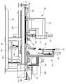
도 3a는 도 1b에 도시된 피어싱 위치에 위치된 피어싱 프레스 유닛과 볼트 조립유닛을 도시한 정면도.
도 3b는 도 3a에서 볼트 조립위치로 이동한 피어싱 프레스 유닛과 볼트 조립유닛 부분을 도시한 정면도.
도 4a는 본 발명에 적용되는 간격재 자동공급유닛의 사시도.
도 4b는 도 4a의 정면도.
도 5는 본 발명에 적용되는 피어싱 프레스 유닛측 프레임에 설치된 볼트조립용 왕복대의 설치상태도.
도 6a는 본 발명에 적용되는 볼트 조립유닛의 정면도.
도 6b는 도 6a의 'C'부 확대도.
도 6c는 도 6a의 일측면도.
도 7은 본 발명에 따른 데크에 피어싱 가공 및 간격재와 볼트를 체결하는 공정순서도.
도 8은 본 발명에 따른 데크에 간격재가 체결되어 있는 상태를 나타내는 사시도.
도 9는 본 발명에 따른 탈형 데크의 간격재 조립 라인에 따른 공정을 도시한 도면.BRIEF DESCRIPTION OF THE DRAWINGS The accompanying drawings, which are incorporated in and constitute a part of the specification, illustrate exemplary embodiments of the invention and, together with the description, serve to explain the principles of the invention, Shall not be construed as limiting.
BRIEF DESCRIPTION OF THE DRAWINGS FIG. 1A is a perspective view of a device for automatically assembling spacers of a de-molding deck according to the present invention. FIG.
Figure 1B is a front view of Figure 1A.
1C is an enlarged view of a portion 'A' in FIG. 1A.
FIG. 1D is an enlarged view of the portion 'B' in FIG. 1A. FIG.
Figure 2a is a perspective view of the piercing press unit applied to Figure la;
Figure 2b is a side view of Figure 2a.
Figure 2c is a partial enlarged view of Figure 2a.
Figure 3a is a front view of the piercing press unit and bolt assembly unit located in the piercing position shown in Figure 1b.
FIG. 3B is a front view showing the piercing press unit and the bolt assembly unit portion moved to the bolt assembling position in FIG. 3A. FIG.
FIG. 4A is a perspective view of an automatic feeding unit for a gap according to the present invention; FIG.
Figure 4b is a front view of Figure 4a.
Fig. 5 is an installation view of a bolt-assembling carriage mounted on a piercing press unit side frame according to the present invention. Fig.
6A is a front view of a bolt assembly unit applied to the present invention.
6B is an enlarged view of a portion 'C' in FIG. 6A.
Figure 6c is a side view of Figure 6a.
7 is a flow chart of a process for piercing a deck according to the present invention and fastening a spacer and a bolt.
8 is a perspective view showing a state in which a spacer is fastened to a deck according to the present invention;
9 is a view showing a process according to the interval reassembling line of the de-molding deck according to the present invention.
아래에서 본 발명은 첨부된 도면에 제시된 실시 예를 참조하여 상세하게 설명이 되지만 제시된 실시 예는 본 발명의 명확한 이해를 위한 예시적인 것으로 본 발명은 이에 제한되지 않는다.DETAILED DESCRIPTION OF THE PREFERRED EMBODIMENTS The present invention will be described in detail below with reference to the embodiments shown in the accompanying drawings, but the present invention is not limited thereto.
도 1a 내지 도 1c에서와 같이 탈형 데크의 간격재 자동 조립 장치(10)는 데크 이송컨베어(12)가 구비된다.As shown in Figs. 1A to 1C, the apparatus for automatically reassembling the deformation-
데크 이송컨베어(12)는 일정폭과 길이를 갖는 데크(5)를 도 3b 및 도 7에 도시된 피어싱 위치(X)까지 이송시킨다. 데크 이송컨베어(12)는 지면에서 수직으로 입설된 다수개의 지지다리(121), 지지다리(121)에 의해 일정 높이에 수평으로 배치되어 있는 롤러 설치대(122), 롤러 설치대(122)에 일정 간격마다 회전 자유롭게 지지되어 있는 다수개의 이송롤러(123)를 구비한다.The
따라서 작업자가 데크(5)를 데크 이송컨베어(12)측 이송롤러(123)에 올려놓고 이송방향(볼트 조립방향)으로 밀어넣으면 데크(5)는 이송롤러(123)에 지지되면서 후술할 피어싱 프레스유닛(20)측으로 이송된다.Therefore, when the operator places the
데크 이송컨베어(12)의 하부에는 간격재(6)를 도 3b 및 도 7에 도시된 볼트 조립위치(Y)까지 이송시키는 간격재 이송컨베어(14)가 구비된다. 간격재 이송컨베어(14)는 데크(5)의 이송라인 하부에 배치되어 간격재(6)를 볼트 조립위치(Y)로 이송시킨다. 간격재 이송컨베어(14)는 간격재 이송컨베어 프레임(141), 간격재 이송컨베어 프레임(141)의 일단에 장착된 구동모터(142), 구동모터(142)에 연동하여 간격재 이송컨베어 프레임(141)의 일측 상단에서 회전 구동하는 구동풀리(143), 간격재 이송컨베어 프레임(141)의 타측 상단에 회전 가능하게 설치되고 구동풀리(143)와 컨베어 벨트(145)를 통해 연결된 종동풀리(144), 컨베어 벨트(145)에 일정 간격마다 설치된 간격재 지그(146)를 구비한다.At the bottom of the
따라서 컨베어 벨트(145)측 간격재 지그(146)에 올려진 간격재(6)는 구동풀리(143)와 종동풀리(144)에 권취되어 반복적으로 회전하는 컨베어 벨트(145)의 이송방향을 따라 간격재(6)를 볼트 조립위치(Y)까지 이동하여 후술할 간격재 자동공급유닛(40)에 의해 파지되어 도 7(나)와 같이 데크(5)에 가공된 피어싱 홀(5a)의 위치로 이동된다.The spacing
데크(5)에 복수개의 피어싱 홀(5a)을 형성시키는 피어싱 프레스유닛(20)이 구비된다. 피어싱 프레스유닛(20)은 데크 이송컨베어(12)의 이송구간 말미에 배치된다. 데크 이송컨베어(12)는 피어싱 상,하 금형(22A,22B)을 통해 피어싱 홀(5a)을 형성시킨 후 볼트 조립위치까지 데크(5)를 이송시킨 후 다시 피어싱 위치로 피어싱 상,하 금형(22A,22B)을 복귀시키는 반복동작을 수행한다.A piercing
도 2a 내지 도 3b와 같이 피어싱 프레스유닛(20)은 프레스 프레임(21)과, 프레스 프레임(21)의 상면에 선형 리니어가이드(29)를 통해 슬라이딩 지지되어 데크(5)의 이송 방향측으로 직선 왕복운동가능게 설치되어 있는 프레스 헤드(22)와, 프레스 헤드(22)의 상부에 수직 방향으로 입설되어 있는 피어싱 실린더(23)와, 프레스 헤드(22)의 하측에 고정 설치된 피어싱 하금형(22B)과, 피어싱 하금형(22B)의 상방에 배치되어 피어싱 실린더(23)에 의해 하강 작동하여 데크(5)에 피어싱 홀을 형성시키는 피어싱 상금형(22A)과, 프레스 프레임(21)에 회전 가능하게 지지되어 상기 프레스 헤드(22)와 스크류 결합되어 있는 프레스 이송스크류(24)와, 프레스 프레임(21)에 장착되어 프레스 이송스크류(24)를 정역회전 구동시키는 프레스 이송모터(25)를 포함하여 구성된다. 프레스 헤드(22)의 하부에는 데크(5)를 받이하는 다수개의 회전롤러(28)가 일정 간격마다 설치되어 있다.2A to 3B, the piercing
따라서 프레스 이송모터(25)의 구동방향에 따라 이송스크류(24)에 의해 프레스 헤드(22)가 왕복 이송을 한다. 이와 동시에 피어싱 위치에서 피어싱 실린더(23)에 의해 피어싱 상금형(22A)이 하강하여 피어싱 하금형(22B)과의 사이에서 데크(5)에 피어싱 홀(5a)을 형성시킨다. 피어싱 홀의 가공후 프레스 헤드(22)는 볼트 조립위치(Y)로 이동한다. 따라서 피어싱 프레스유닛(20)에서 피어싱 상,하 금형(22A,22B)은 피어싱 위치(X)에서 피어싱 홀을 가공한 후 볼트 조립위치(Y)로 이동하고 다시 피어싱 위치(X)로 복귀하는 왕복 운동을 반복하여 수행한다.Therefore, the
본 실시 예에서 데크(50)에는 폭 방향으로 3개의 간격재(6)가 한 번에 조립되는 것으로, 1회 가공의 피어싱 홀은 피어싱 상금형(22A)에 의해 6개씩 형성된다. 본 발명은 예시된 피어싱 홀의 개수나 배열에 한정되어 적용되는 것은 아니다.In the present embodiment, three
여기서, 프레스 헤드(22)측에는 데크(5)의 최초 피어싱 위치를 결정하기 위한 스톱퍼 유닛(26)이 설치된다.Here, on the side of the
도 2a 내지 도 2c와 같이 스톱퍼 유닛(26)은 프레스 헤드(22)의 하면에 고정되어 선단에 돌출 고정된 스톱퍼 받침대(261)와, 스톱퍼 받침대(261)에 수직방향으로 상하 이동가능하게 지지되어 있는 스톱퍼 승강축(262)과, 스톱퍼 승강축(262)의 상단에 고정되어 있는 스톱퍼 블록(263)과, 스톱퍼 블록(263)에 고정되어 있는 데크 스톱퍼(264)와, 스톱퍼 받침대(261)에 고정 설치되고 작동로드가 상기 스톱퍼 블록(263)에 연결되어 작동 방향에 따라 데크 스톱퍼(264)를 데크 고정위치와 데크 해제위치로 이동시키는 스톱퍼 실린더(265)를 포함하여 구성된다.2A to 2C, the
따라서, 데크(50)가 최초로 이송하여 피어싱 프레스유닛(20)측으로 인입되는 경우 스톱퍼 실린더(265)에 의해 데크 스톱퍼(264)가 상승하여 데크(5)의 최초 진입 위치를 제한하고, 이후에는 데크 스톱퍼(264)가 스톱퍼 실린더(265)의 복귀 동작으로 하강하여 데크(5)가 피치 이동하는데 방해를 주지 않게 된다. 피치 이동은 데크의 길이 방향으로 설치되는 간격재(6)의 설치 간격을 의미한다.Therefore, when the deck 50 is first conveyed to the side of the piercing
피어싱 프레스유닛(20)측 프레스 프레임(21)에 데크(6)를 클램프/언클램프 동작시키는 한 쌍의 데크 클램핑유닛(30A,30B)이 설치되어 있다. 한 쌍의 데크 클램핑유닛(30A,30B)은 데크(6)의 양쪽 폭 방향에 동일한 구조를 가지고 설치되어 있다. 한 쌍의 데크 클램핑유닛(30A,30B)은 피어싱 프레스 유닛(20)의 피어싱 홀 가공과 볼트가 조립되는 동안에 데크(5)를 클램핑하고, 데크(5)의 배출 방향 이송시 데크를 언클램프시킨다.A pair of
한 쌍의 데크 클램핑유닛(30A,30B)은, 프레스 프레임(21)의 상단에 위치 고정된 클램프 하부고정판(31)과, 클램프 하부고정판(31)에 입설된 실린더 행거(32)와, 실린더 행거(32)의 상단에 고정 설치된 클램프 실린더(33)와, 실린더 행거(32)에 수직 방향으로 이동 가능하게 지지되어 클램프 실린더(33)에 의해 승강 동작하는 클램프 상부가동판(34)을 포함하여 구성된다.The pair of
따라서 클램프 실린더(33)의 상승 동작에 의해 클램프 상부가동판(34)이 상방으로 상승 위치한 상태에서 데크(5)는 볼트 조립위치(Y)로 이동 완료하고, 이 후 클램프 실린더(33)의 하강 동작에 의해 상부가동판(34)이 클램프 하부고정판(31)과 물림하여 데크(5)를 클램핑한다.The
피어싱 프레스유닛(20)측 프레스 프레임(21) 내부에 간격재 자동공급유닛(40)이 설치되어 있다. 간격재 자동공급유닛(40)은 피어싱 상,하 금형(22A,22B)이 피어싱 위치(X)로 복귀시 간격재 이송컨베어(14)에 안착된 간격재(6)를 클램핑 한 상태로 상승시켜 데크(5)의 하면에서 도 7(나)와 같이 피어싱 홀(5a)에 밀착되게 위치시킨 후 볼트(7) 체결이 끝나면 원위치로 복귀한다.An automatic
도 4a 및 도 4b와 같이 간격재 자동공급유닛(40)은 볼트(7)의 체결 위치의 하방에 배치된 리프팅업/다운 테이블 지지대(41)와, 리프팅업/다운 테이블 지지대(41)의 일단에 수직 방향으로 설치된 리프팅 테이블 실린더(42)와, 리프팅업/다운 테이블 지지대(41)에 승강 이동가능하게 지지되고 동시에 리프팅 테이블 실린더(42)에 연결되어 승강 이동 동작하는 리프팅 테이블(43)과, 리프팅 테이블(43)의 상면에 고정 입설되고 상단에 간격재 고정자(441)를 갖는 리프팅 고정클램프(44)와, 리프팅 고정클램프(44)의 하부측에 수직방향으로 고정 설치된 가동자 클램핑 위치결정용 실린더(45)와, 리프팅 고정클램프(44)에 승강 이동가능하게 지지되고 가동자 클램핑 위치결정용 실린더(45)에 연결되어 승강동작하는 클램프 슬라이더(46)와, 클램프 슬라이더(46)에 수평방향으로 고정 설치된 가동자 클램핑 실린더(47)와, 클램프 슬라이더(46)에 수평 방향으로 이동가능하게 지지되고 동시에 가동자 클램핑 실린더(47)에 연결되어 수평방향으로 이동하면서 간격재(6)를 클램프/언클램프시키는 간격재 고정용 가동자(48)를 포함하여 구성된다.4A and 4B, the automatic
따라서 리프팅 테이블 실린더(42)의 하강 동작 완료시 리프팅 업 테이블(43)은 하강 위치하게 되고, 이 상태에서 가동자 클램프 위치결정용 실린더(45)의 하강 동작에 의해 간격재(6)가 간격재 고정자(441)측에 위치되고, 이 상태에서 가동자 클램핑 실린더(47)가 간격재 고정용 가동자(48)를 이동시켜 간격재(6)를 도 4b와 같이 클램핑하고, 이어서 리프팅 테이블 실린더(42)의 상승 동작으로 리프팅 업 테이블(43)이 상방으로 상승완료하여 도 7(나)와 같이 간격재(6)를 데크(5)의 밑면에서 피어싱 홀(5a)측에 밀착시킨다. 이후 볼트(7)의 체결 후 다시 간격재 자동공급유닛(40)은 위 동작을 반복하게 된다.Therefore, when the
볼트(7)를 공급받아 간격재(6)를 데크(5)에 결합시키는 볼트 조립유닛(60)이 구비된다. 볼트 조립유닛(60)은 도 3a와 같이 피어싱 프레스유닛(20)측 프레스 헤드(22)가 피어싱 위치(X)로 복귀 완료시 데크(5)의 상면에서 피어싱 홀을 통해 볼트(7)를 체결하여 간격재(6)를 데크(5)에 결합시킨 후 원위치로 복귀한다.And a
도 3 및 도 6과 같이 볼트 조립유닛(60)은 피어싱 프레스 유닛(20)측 프레스 프레임(21)의 상면에 지지되어 간격재 볼트 조립 위치와 대기위치를 직선운동으로 왕복 이동가능하게 설치된 볼트조립용 왕복대(62)와, 프레스 프레임(21)측에 고정되어 작동로드가 볼트조립용 왕복대(62)에 연결되어 볼트조립용 왕복대(62)를 왕복 운동시키는 왕복실린더(61)와, 볼트조립용 왕복대(62)에 수직 방향으로 고정 설치된 볼트체결용 삽입실린더(63)와, 볼트조립용 왕복대(62)에 일단이 상하 이동가능하게 지지되어 볼트체결용 삽입실린더(63)에 의해 상하 이동동작하는 연결대(64)와, 연결대(64)의 타단측 상방에 수직 방향으로 입설된 볼트 체결모터(65)와, 연결대(64)의 타단측 하방에 고정 설치되고 볼트(7)가 인입되는 볼트 인입공(661)을 갖는 볼트 소켓(66)과, 볼트 체결모터(65)의 구동축에 직결되어 볼트 소켓(66)에 인입된 볼트(7)를 회전 구동시키는 볼트 드라이버 샤프트(67)를 포함하여 구성된다. 볼트 소켓(66)은 볼트(7)의 체결 후 볼트체결용 삽입실린더(63)의 상승 동작시 볼트(7)로부터 분리될 수 있도록 힌지 결합된 한 쌍의 조우(661)를 갖는다.3 and 6, the
여기서 볼트 인입공(661)은 호스(미도시)를 통해 주지의 볼트 정렬공급기(200)와 연결된다. 볼트 정렬공급기(200)는 다량의 볼트를 순서와 방향을 조절하여 낱개씩 호스를 통해 볼트 인입공(661)으로 공급한다. 볼트 정렬공급기(200)는 이미 알려진 주지의 기술이므로 상세한 구성 및 동작 설명은 생략한다.The
한편, 간격재(6)가 체결된 데크를 반출해내는 데크 반출컨베어(80)가 구비된다. 데크 반출컨베어(80)는 데크를 반출해내는 방향에 배치된다. 데크 반출컨베어(80)는 반출컨베어 프레임(81)과, 반출컨베어 프레임(81)의 상면에 직선 구간을 가지고 회전 구동하는 반출컨베어벨트(82)와, 반출컨베어벨트(82)를 회전구동시키는 반출구동모터(도시안됨)을 갖는다.On the other hand, a deck carry-out
이와 같이 구성된 본 실시 예의 동작 및 작용을 설명한다.The operation and operation of the present embodiment thus configured will be described.
먼저, 도 9의 공정도에서 알 수 있는 바와 같이 3방향의 조립 라인이 합치되는 곳에서 간격재(6)가 볼트(7)의 체결로 데크(5)에 자동 조립된다.First, as can be seen from the process drawing of Fig. 9, the
즉, 제 1방향에서 데크(5)는 데크 이송컨베어(12)에 의한 로딩(A1)과 스톱퍼유닛(26)에 의한 정렬(A2) 및 피어싱 프레스 유닛(20)에 의한 피어싱 가공(A3)을 거쳐 간격재 조립(A4) 위치로 이동하는 공정이 진행된다.That is, in the first direction, the
제 2방향에서 간격재(6)는 간격재 이송컨베어(14)에 의한 정렬(B1) 및 이송(B2), 간격재 자동공급유닛(40)에 의한 간격재 자동공급(B3)을 통해 간격재 조립(A4) 위치로 이동하는 공정이 진행된다.The
나머지 제 3 방향에서 볼트(6)는 볼트 정렬공급기(200)에 의한 자동 공급(C1) 후 볼트 조립유닛(60)의 전진(C2) 및 하강(C3)을 통해 볼트 조립 위치로 이동한 후 볼트(7)를 체결(C4)하는 공정이 진행된다.In the remaining third direction, the
이같이 본 탈형 데크의 간격재 자동 조립 장치는 간격재(6)와 볼트(7)를 볼트 체결 위치(Y)로 이송시키면서 데크(5)에 가공된 피어싱 홀에 그 체결 위치에서 간격재(6)를 밀착 위치시킨 후 볼트(7)를 체결하는 반복적인 작업을 수행하는 것이다.The apparatus for automatic re-assembly of the de-molding deck of the de-molding deck as described above is characterized in that the
본 실시 예에서는 데크(5)에 폭 방향으로 1열마다 3개소에 간격재(6)를 배치하여 볼트(7)를 체결하는 반복적인 작업을 수회 시행한 후 데크 반출컨베어(80)를 통해 반출된다.In this embodiment, the
이를 각 장치의 동작을 통해 상세히 살펴본다.The operation of each device will be described in detail.
작업자가 데크(5)를 데크 이송컨베어(12)측 이송롤러(123)에 올려놓고 이송방향(피어싱 가공방향)으로 밀어넣으면 데크(5)는 피어싱 홀을 가공하는 피어싱 프레스유닛(20)측으로 원할하게 이송된 후 스톱퍼 유닛(26)측 데크 스톱퍼(264)에 멈춤되어 위치가 고정된다.When the worker puts the
이 상태에서 피어싱 프레스유닛(20)은 피어싱실린더(23)를 구동시켜 피어싱 상,하금형(22A,22B)을 통해 피어싱 홀(5a)을 도 7(가)와 같이 형성시킨 후 볼트 조립위치(Y)까지 데크(5)를 이송시킨 후 다시 피어싱 위치(X)로 피어싱 상,하 금형(22A,22B)을 복귀시키는 반복동작을 수행한다.In this state, the piercing
이후 프레스 헤드(22)는 피어싱 상,하 금형(22A,22B)을 통해 피어싱 위치(X)에서 피어싱 홀을 가공한 후 볼트 조립위치(Y)로 이동하고 다시 피어싱 위치로 복귀하는 왕복동작을 반복한다.Thereafter, the
이때 한 쌍의 데크 클램핑유닛(30A,30B)은 클램프 실린더(33)의 작동방향을 제어하여 데크(5)의 피어싱 홀 가공시 그리고 간격재의 볼팅 조립되는 동안 데크(5)를 클램핑하고, 데크(5)의 반출 방향 이송시 데크의 클램핑을 해제시킨다.At this time, a pair of
한편, 간격재 이송컨베어(14)측 간격재 지그(146)에 올려진 간격재(6)는 컨베어 벨트(145)의 이송방향을 따라 간격재(6)를 볼트 조립위치까지 이동한 후 간격재 자동공급유닛(40)에 의해 순차적으로 간격재 고정용 가동자(48)와 간격재 고정자(441)의 사이에 파지되어 데크(5)의 조립 위치로 리프팅 테이블 실린더(42)의 업 동작으로 이동된다. 그 결과 데크(5)에 가공된 피어싱 홀(5a)의 밑면에 도 7(나)와 같이 간격재(6)가 밀착되어 있게 된다.On the other hand, the spacing
이 상태에서 볼트 조립유닛(60)은 볼트소켓(66)내로 볼트(7)를 공급받은 후 볼트조립용 왕복대(62)를 통해 볼트 조립위치(Y)로 이동한 후 볼트 체결용 삽입실린더(63)가 하강동작하여 볼트 소켓(66)이 데크(5)의 피어싱 홀에 위치되고, 이 상태에서 볼트 체결모터(65)가 회전 구동하여 데크(5)의 상면에서 피어싱 홀을 통해 볼트(7)를 체결하여 도 7(다)와 같이 간격재(6)를 데크(5)에 결합시킨 후 원위치로 복귀한다. 이후에는 도 7의 (가),(나),(다)의 공정을 반복하게 된다.In this state, the
이같은 동작은 데크에 길이 방향으로 매 피치마다 간격재를 볼트 결합시키기 위해 반복된 후 최종적으로 데크 반출컨베어(80)를 통해 배출방향으로 반출된다.This operation is repeated to bolt the gap to the deck at intervals of each pitch in the longitudinal direction, and finally to the discharge direction through the
이와 같이 본 발명에 따르면, 데크(5)에 피어싱 홀을 정위치에 가공할 수 있고, 정렬 가공된 피어싱 홀에 연속적으로 볼트(7)를 조립하여 간격재(6)를 데크(5)에 자동 조립할 수 있어 불량 발생이 없고 조립시간이 단축되어 생산성이 향상된다.As described above, according to the present invention, it is possible to process the piercing hole in the
지금까지 본 발명은 제시된 실시 예를 참조하여 상세하게 설명이 되었지만 이 분야에서 통상의 지식을 가진 자는 제시된 실시 예를 참조하여 본 발명의 기술적 사상을 벗어나지 않는 범위에서 다양한 변형 및 수정 발명을 만들 수 있을 것이다. 본 발명은 이와 같은 변형 및 수정 발명에 의하여 제한되지 않으며 다만 아래에 첨부된 청구범위에 의하여 제한된다.While the present invention has been particularly shown and described with reference to exemplary embodiments thereof, it is evident that many alternatives, modifications and variations will be apparent to those skilled in the art in light of the above teachings. will be. The invention is not limited by these variations and modifications, but is limited only by the claims appended hereto.
12: 데크 이송컨베어
14: 간격재 이송컨베어
20: 피어싱 프레스유닛
30A,30: 데크 클램핑유닛
40: 간격재 자동공급유닛
60: 볼트 조립유닛
80: 데크 반출컨베어12: Deck conveying conveyor
14: interval retransfer conveyor
20: Piercing press unit
30A, 30: Deck clamping unit
40: Interval automatic feed unit
60: Bolt assembly unit
80: Deck conveying conveyor
Claims (6)
Translated fromKorean상기 피어싱 프레스유닛(20)은,
프레스 프레임(21)과; 상기 프레스 프레임(21)의 상면에 슬라이딩 지지되어 피어싱 위치와 볼트 조립위치를 왕복하는 프레스 헤드(22)와; 상기 프레스 헤드(22)에 수직 방향으로 입설되어 있는 피어싱 실린더(23)와; 상기 프레스 헤드(22)의 하측에 고정 설치된 피어싱 하금형(22B)과; 상기 피어싱 하금형(22B)의 상방에 배치되어 상기 피어싱 실린더(23)에 의해 하강 작동하여 상기 데크(5)에 피어싱 홀을 형성시키는 피어싱 상금형(22A)과; 상기 프레스 프레임(21)에 회전 가능하게 지지되어 상기 프레스 헤드(22)와 스크류 결합되어 있는 프레스 이송스크류(24)와; 상기 프레스 프레임(21)에 장착되어 상기 프레스 이송스크류(24)를 정역회전 구동시키는 프레스 이송모터(25)를 포함하여 구성된 것을 특징으로 하는 탈형 데크의 간격재 자동 조립 장치.A deck conveying conveyor 12 for conveying the deck 5 having a predetermined width and length to the piercing position X; An interval re-conveying conveyor 14 disposed below the conveying line of the deck 5 for conveying the spacing member 6 to the bolt assembling position Y; A plurality of piercing holes are formed in the deck 5 through the piercing upper and lower dies 22A and 22B and then the deck 5 is transferred to the bolt assembling position and then pierced to the piercing position with the lower and upper dies 22A, 22B) of the piercing press unit (20); A pair of deck clamping units (30A, 30B) clamping the deck (5) during piercing and bolt assembly of the piercing press unit (20) and unclamping the deck during delivery of the deck (5) in the discharge direction; When the returning to the piercing position of the piercing upper and lower dies 22A and 22B is completed, the spacing member 6 seated on the spacing re-conveying conveyor 14 is lifted up to be brought into close contact with the piercing hole An automatic interval supply unit 40 for returning to the home position after tightening the bolts 7; When the piercing press unit 20 returns to the piercing position, the bolt 7 is fastened to the upper surface of the deck 5 through the piercing hole to couple the spacer 6 to the deck 5, A bolt assembly unit 60; And a deck carrying conveyor (80) for taking out the deck (5) to which the spacer (6) is fastened,
The piercing press unit (20)
A press frame 21; A press head 22 slidably supported on an upper surface of the press frame 21 to reciprocate between a piercing position and a bolt assembly position; A piercing cylinder (23) extending perpendicularly to the press head (22); A piercing die 22B fixed to the lower side of the press head 22; A piercing upper mold 22A disposed above the piercing metal mold 22B and lowered by the piercing cylinder 23 to form a piercing hole in the deck 5; A press conveying screw (24) rotatably supported on the press frame (21) and screwed to the press head (22); And a press conveying motor (25) mounted on the press frame (21) for driving the press conveying screw (24) in normal and rotational directions.
상기 프레스 헤드(22)측에는 데크(5)의 피어싱 위치를 결정하기 위한 스톱퍼 유닛(26)이 설치되고;
상기 스톱퍼 유닛(26)은,
상기 프레스 헤드(22)의 하면에 고정되어 선단에 돌출 고정된 스톱퍼 받침대(261)와;
상기 스톱퍼 받침대(261)에 수직방향으로 상하 이동가능하게 지지되어 있는 스톱퍼 승강축(262)과;
상기 스톱퍼 승강축(262)의 상단에 고정되어 있는 스톱퍼 블록(263)과;
상기 스톱퍼 블록(263)에 고정되어 있는 데크 스톱퍼(264)와;
상기 스톱퍼 받침대(261)에 고정 설치되고 작동로드가 상기 스톱퍼 블록(263)에 연결되어 작동 방향에 따라 상기 데크 스톱퍼(264)를 데크 고정위치와 데크 해제위치로 이동시키는 스톱퍼 실린더(265)를 포함한 것을 특징으로 하는 탈형 데크의 간격재 자동 조립 장치.The method according to claim 1,
A stopper unit 26 for determining a piercing position of the deck 5 is provided on the side of the press head 22;
The stopper unit (26)
A stopper pedestal 261 fixed to the lower surface of the press head 22 and fixed to the front end thereof;
A stopper lifting shaft 262 vertically movably supported by the stopper pedestal 261 so as to be vertically movable;
A stopper block 263 fixed to an upper end of the stopper lifting shaft 262;
A deck stopper 264 fixed to the stopper block 263;
And a stopper cylinder 265 fixed to the stopper pedestal 261 and connected to the stopper block 263 to move the deck stopper 264 to the deck releasing position and the deck releasing position Wherein the automatic de-molding device comprises:
상기 한 쌍의 데크 클램핑유닛(30A,30B)은,
상기 프레스 프레임(21)의 상단에 위치 고정된 클램프 하부고정판(31)과;
상기 클램프 하부고정판(31)에 입설된 실린더 행거(32)와;
상기 실린더 행거(32)의 상단에 고정 설치된 클램프 실린더(33)와;
상기 실린더 행거(32)에 수직 방향으로 이동 가능하게 지지되어 상기 클램프 실린더(33)에 의해 승강 동작하는 클램프 상부가동판(34)을 포함한 것을 특징으로 하는 탈형 데크의 간격재 자동 조립 장치.The method according to claim 1,
The pair of deck clamping units (30A, 30B)
A clamp lower fixing plate 31 fixed to the upper end of the press frame 21;
A cylinder hanger 32 installed in the clamp lower fixing plate 31;
A clamp cylinder 33 fixed to the upper end of the cylinder hanger 32;
And a clamp upper movable plate (34) which is supported by the cylinder hanger (32) so as to be vertically movable and which is moved up and down by the clamp cylinder (33).
상기 간격재 자동공급유닛(40)은,
볼트 조립 위치(Y)의 하방에 배치된 리프팅업/다운 테이블 지지대(41)와;
상기 리프팅업/다운 테이블 지지대(41)의 일단에 수직 방향으로 설치된 리프팅 테이블 실린더(42)와;
상기 리프팅업/다운 테이블 지지대(41)에 승강 이동가능하게 지지되고 동시에 상기 리프팅 테이블 실린더(42)에 연결되어 승강 이동 동작하는 리프팅 테이블(43)과;
상기 리프팅 테이블(43)의 상면에 고정 입설되고 상단에 간격재 고정자(441)를 갖는 리프팅 고정클램프(44)와;
상기 리프팅 고정클램프(44)의 하부측에 수직방향으로 고정 설치된 가동자 클램핑 위치결정용 실린더(45)와;
상기 리프팅 고정클램프(44)에 승강 이동가능하게 지지되고, 가동자 클램핑 위치결정용 실린더(45)에 연결되어 승강동작하는 클램프 슬라이더(46)와;
상기 클램프 슬라이더(46)에 수평방향으로 고정 설치된 가동자 클램핑 실린더(47)와;
상기 클램프 슬라이더(46)에 수평 방향으로 이동가능하게 지지되고, 상기 가동자 클램핑 실린더(47)에 연결되어 수평방향으로 이동하면서 간격재를 클램프/언클램프시키는 간격재 고정용 가동자(48)를 포함한 것을 특징으로 하는 탈형 데크의 간격재 자동 조립 장치.The method according to claim 1,
The automatic interval supply unit (40)
A lifting up / down table support 41 disposed below the bolt assembly position Y;
A lifting table cylinder (42) vertically installed at one end of the lifting up / down table support (41);
A lifting table 43 supported on the lifting up / down table support 41 so as to be movable up and down and connected to the lifting table cylinder 42 to move up and down;
A lifting clamp 44 fixedly installed on the upper surface of the lifting table 43 and having a spacing remover 441 at the upper end thereof;
A mover clamping positioning cylinder 45 fixed to the lower side of the lifting fixed clamp 44 in the vertical direction;
A clamp slider (46) supported on the lifting fixed clamp (44) so as to be movable up and down, and connected to the mover clamping position determining cylinder (45) to move up and down;
A mover clamping cylinder 47 fixed to the clamp slider 46 in the horizontal direction;
A movable member 48 which is movably supported by the clamp slider 46 in a horizontal direction and which is connected to the mover clamping cylinder 47 and moves in the horizontal direction to clamp / And the automatic deformation device for automatically deforesting the decking deck.
상기 볼트 조립유닛(60)은,
상기 피어싱 프레스 유닛(20)측에 지지되어 간격재 볼트 조립 위치와 대기위치를 직선운동으로 왕복 이동가능하게 설치된 볼트조립용 왕복대(62)와;
상기 볼트조립용 왕복대(62)를 왕복 운동시키는 왕복실린더(61)와;
상기 볼트조립용 왕복대(62)에 수직 방향으로 고정 설치된 볼트체결용 삽입실린더(63)와;
상기 볼트조립용 왕복대(62)에 일단이 상하 이동가능하게 지지되어 상기 볼트체결용 삽입실린더(63)에 의해 상하 이동동작하는 연결대(64)와;
상기 연결대(64)의 타단측 상방에 수직 방향으로 입설된 볼트 체결모터(65)와;
상기 연결대(64)의 타단측 하방에 고정 설치되고 볼트 인입공(661)을 통해 볼트(7)를 수용하고 나사 체결 후 해당 볼트(7)와 분리되는 볼트 소켓(66)과;
상기 볼트 체결모터(65)의 구동축에 직결되어 볼트 소켓(66)에 인입된 볼트(7)를 회전 구동시키는 볼트 드라이버 샤프트(67);를 포함한 것을 특징으로 하는 탈형 데크의 간격재 자동 조립 장치.The method according to claim 1,
The bolt assembly unit (60)
A bolt assembling reciprocating support 62 supported on the piercing press unit 20 side so as to reciprocate in a linear motion with the spacing bolt assembling position and the standby position;
A reciprocating cylinder 61 for reciprocating the bolt-assembling carriage 62;
A bolt fastening insertion cylinder 63 fixed to the bolt assembling carriage 62 in a vertical direction;
A connecting rod 64 having one end vertically movably supported by the bolt-assembling carriage 62 and moving up and down by the bolt-fastening insertion cylinder 63;
A bolt fastening motor 65 installed vertically above the other end side of the connecting rod 64;
A bolt socket 66 fixed to the lower end of the connecting rod 64 and receiving the bolt 7 through the bolt insertion hole 661 and separated from the bolt 7 after screwing;
And a bolt driver shaft (67) for directly driving the bolt (7) inserted into the bolt socket (66) directly to the drive shaft of the bolt fastening motor (65).
Priority Applications (1)
| Application Number | Priority Date | Filing Date | Title |
|---|---|---|---|
| KR1020150082169AKR101729488B1 (en) | 2015-06-10 | 2015-06-10 | Spacer automatic assembly device of form removal deck |
Applications Claiming Priority (1)
| Application Number | Priority Date | Filing Date | Title |
|---|---|---|---|
| KR1020150082169AKR101729488B1 (en) | 2015-06-10 | 2015-06-10 | Spacer automatic assembly device of form removal deck |
Publications (2)
| Publication Number | Publication Date |
|---|---|
| KR20160145445A KR20160145445A (en) | 2016-12-20 |
| KR101729488B1true KR101729488B1 (en) | 2017-04-24 |
Family
ID=57734362
Family Applications (1)
| Application Number | Title | Priority Date | Filing Date |
|---|---|---|---|
| KR1020150082169AActiveKR101729488B1 (en) | 2015-06-10 | 2015-06-10 | Spacer automatic assembly device of form removal deck |
Country Status (1)
| Country | Link |
|---|---|
| KR (1) | KR101729488B1 (en) |
Families Citing this family (4)
| Publication number | Priority date | Publication date | Assignee | Title |
|---|---|---|---|---|
| CN109671592A (en)* | 2018-02-27 | 2019-04-23 | 温州市科泓机器人科技有限公司 | The manufacturing process of contactor assembly |
| CN108422168A (en)* | 2018-05-08 | 2018-08-21 | 广州隆控机电设备有限公司 | A kind of switching mechanism and stud orientation arrangement apparatus |
| CN110773988B (en)* | 2019-07-31 | 2024-04-16 | 扬州市创搏机械制造有限公司 | Automatic fixed-length screwing device for ash removal air tap of dust remover |
| CN114434621B (en)* | 2022-01-28 | 2024-05-07 | 智鑫隆科技(广东)有限公司 | Form removing device |
Citations (2)
| Publication number | Priority date | Publication date | Assignee | Title |
|---|---|---|---|---|
| KR101356720B1 (en)* | 2013-09-16 | 2014-01-28 | 주식회사 덕신하우징 | Deck plate auto assembly system |
| KR101481951B1 (en)* | 2014-07-28 | 2015-01-14 | 주식회사 덕신하우징 | Deck Plate Auto Bolting Apparatus |
Family Cites Families (2)
| Publication number | Priority date | Publication date | Assignee | Title |
|---|---|---|---|---|
| KR101237323B1 (en) | 2012-08-06 | 2013-02-28 | 주식회사 덕신하우징 | Spacer for stripping deck |
| KR101503015B1 (en) | 2014-04-28 | 2015-03-16 | 김준범 | Apparatus for Assembling Bolts Automatically |
- 2015
- 2015-06-10KRKR1020150082169Apatent/KR101729488B1/enactiveActive
Patent Citations (2)
| Publication number | Priority date | Publication date | Assignee | Title |
|---|---|---|---|---|
| KR101356720B1 (en)* | 2013-09-16 | 2014-01-28 | 주식회사 덕신하우징 | Deck plate auto assembly system |
| KR101481951B1 (en)* | 2014-07-28 | 2015-01-14 | 주식회사 덕신하우징 | Deck Plate Auto Bolting Apparatus |
Also Published As
| Publication number | Publication date |
|---|---|
| KR20160145445A (en) | 2016-12-20 |
Similar Documents
| Publication | Publication Date | Title |
|---|---|---|
| CN108568707B (en) | Truss floor carrier plate assembly production line | |
| CN205397379U (en) | Automatic plate feeder | |
| KR101729488B1 (en) | Spacer automatic assembly device of form removal deck | |
| KR100897986B1 (en) | Four-way accumulator pipe residual stress relief device | |
| CN108365495B (en) | A PCB board automatic assembly welding equipment | |
| CN113410965B (en) | Winding equipment for block stator and operation method thereof | |
| KR101481951B1 (en) | Deck Plate Auto Bolting Apparatus | |
| KR100485120B1 (en) | Auto-riveting machine | |
| CN109361297A (en) | Embedded PMSM rotor magnet steel automatic assembly equipment | |
| CN116493798B (en) | Electric bicycle frame welding device and welding method | |
| CN117047395B (en) | Pipe fitting assembling and welding production line and working method thereof | |
| CN209919292U (en) | Automatic assembling machine for hinge waist cover self-discharging foot component | |
| KR102358140B1 (en) | Bending machine of welded steel mesh | |
| CN222493289U (en) | A rod conveying device | |
| CN118578172A (en) | A rod feeding device and control method thereof | |
| CN110774439B (en) | Track slab spiral reinforcement casing installation machine | |
| CN111473055B (en) | Automatic ball loading device for bearing support and assembling method thereof | |
| CN220349096U (en) | Automatic welding machine for butt joint of small-caliber pipes | |
| CN117020516A (en) | Steel bar truss floor carrier plate production line | |
| KR101509182B1 (en) | Forming apparatus for connecting part of concrete reinforcements | |
| CN118106547A (en) | Continuous unloader of skeleton car crossbeam | |
| KR100818022B1 (en) | Crankshaft Material Feeder | |
| CN117620810A (en) | Full-automatic high-efficient pipe double-end chamfer device | |
| CN208257086U (en) | A kind of automatic assembly welding equipment of pcb board | |
| CN117102367A (en) | A photovoltaic panel frame loading and clamping mechanism and punching device |
Legal Events
| Date | Code | Title | Description |
|---|---|---|---|
| A201 | Request for examination | ||
| PA0109 | Patent application | Patent event code:PA01091R01D Comment text:Patent Application Patent event date:20150610 | |
| PA0201 | Request for examination | ||
| E902 | Notification of reason for refusal | ||
| PE0902 | Notice of grounds for rejection | Comment text:Notification of reason for refusal Patent event date:20160727 Patent event code:PE09021S01D | |
| PG1501 | Laying open of application | ||
| E701 | Decision to grant or registration of patent right | ||
| PE0701 | Decision of registration | Patent event code:PE07011S01D Comment text:Decision to Grant Registration Patent event date:20170117 | |
| GRNT | Written decision to grant | ||
| PR0701 | Registration of establishment | Comment text:Registration of Establishment Patent event date:20170418 Patent event code:PR07011E01D | |
| PR1002 | Payment of registration fee | Payment date:20170418 End annual number:3 Start annual number:1 | |
| PG1601 | Publication of registration | ||
| PR1001 | Payment of annual fee | Payment date:20200417 Start annual number:4 End annual number:4 | |
| PR1001 | Payment of annual fee | Payment date:20210415 Start annual number:5 End annual number:5 | |
| PR1001 | Payment of annual fee | Payment date:20220407 Start annual number:6 End annual number:6 | |
| PR1001 | Payment of annual fee | Payment date:20230410 Start annual number:7 End annual number:7 | |
| PR1001 | Payment of annual fee | Payment date:20240411 Start annual number:8 End annual number:8 |