KR101721938B1 - A monitoring device for welding parts of a steam generator - Google Patents
A monitoring device for welding parts of a steam generatorDownload PDFInfo
- Publication number
- KR101721938B1 KR101721938B1KR1020150088690AKR20150088690AKR101721938B1KR 101721938 B1KR101721938 B1KR 101721938B1KR 1020150088690 AKR1020150088690 AKR 1020150088690AKR 20150088690 AKR20150088690 AKR 20150088690AKR 101721938 B1KR101721938 B1KR 101721938B1
- Authority
- KR
- South Korea
- Prior art keywords
- guide
- tubes
- tube
- guide tube
- guide tubes
- Prior art date
- Legal status (The legal status is an assumption and is not a legal conclusion. Google has not performed a legal analysis and makes no representation as to the accuracy of the status listed.)
- Expired - Fee Related
Links
Images


Classifications
- G—PHYSICS
- G21—NUCLEAR PHYSICS; NUCLEAR ENGINEERING
- G21C—NUCLEAR REACTORS
- G21C17/00—Monitoring; Testing ; Maintaining
- G21C17/003—Remote inspection of vessels, e.g. pressure vessels
- G21C17/013—Inspection vehicles
- G—PHYSICS
- G01—MEASURING; TESTING
- G01N—INVESTIGATING OR ANALYSING MATERIALS BY DETERMINING THEIR CHEMICAL OR PHYSICAL PROPERTIES
- G01N21/00—Investigating or analysing materials by the use of optical means, i.e. using sub-millimetre waves, infrared, visible or ultraviolet light
- G01N21/84—Systems specially adapted for particular applications
- G01N21/88—Investigating the presence of flaws or contamination
- G01N21/8803—Visual inspection
- G—PHYSICS
- G01—MEASURING; TESTING
- G01N—INVESTIGATING OR ANALYSING MATERIALS BY DETERMINING THEIR CHEMICAL OR PHYSICAL PROPERTIES
- G01N2201/00—Features of devices classified in G01N21/00
- G01N2201/06—Illumination; Optics
- G01N2201/062—LED's
- Y—GENERAL TAGGING OF NEW TECHNOLOGICAL DEVELOPMENTS; GENERAL TAGGING OF CROSS-SECTIONAL TECHNOLOGIES SPANNING OVER SEVERAL SECTIONS OF THE IPC; TECHNICAL SUBJECTS COVERED BY FORMER USPC CROSS-REFERENCE ART COLLECTIONS [XRACs] AND DIGESTS
- Y02—TECHNOLOGIES OR APPLICATIONS FOR MITIGATION OR ADAPTATION AGAINST CLIMATE CHANGE
- Y02E—REDUCTION OF GREENHOUSE GAS [GHG] EMISSIONS, RELATED TO ENERGY GENERATION, TRANSMISSION OR DISTRIBUTION
- Y02E30/00—Energy generation of nuclear origin
- Y02E30/30—Nuclear fission reactors
Landscapes
- Physics & Mathematics (AREA)
- Engineering & Computer Science (AREA)
- Plasma & Fusion (AREA)
- General Engineering & Computer Science (AREA)
- High Energy & Nuclear Physics (AREA)
- Health & Medical Sciences (AREA)
- Life Sciences & Earth Sciences (AREA)
- Chemical & Material Sciences (AREA)
- Analytical Chemistry (AREA)
- Biochemistry (AREA)
- General Health & Medical Sciences (AREA)
- General Physics & Mathematics (AREA)
- Immunology (AREA)
- Pathology (AREA)
- Monitoring And Testing Of Nuclear Reactors (AREA)
Abstract
Translated fromKoreanDescription
Translated fromKorean본 발명은 증기 발생기의 용접부 검사 장치에 관한 것으로서, 구체적으로는 증기 발생기의 전열관들을 지지하는 지지판이 전열관을 둘러싸는 슈라우드에 용접된 부분을 검사하는 검사 장치에 관한 것이다.The present invention relates to an apparatus for inspecting a weld portion of a steam generator, and more particularly, to an inspection apparatus for inspecting a portion of a support plate supporting a heat transfer tube of a steam generator welded to a shroud surrounding a heat transfer tube.
원자력 발전소의 증기 발생기는, 원자로에서 생성된 방사능이 함유된 고온 고압의 1차 유체가 전열관 내부를 흐르면서 이 전열관의 외부에 공급되는 2차 유체에 열을 전달하여 증기를 발생시키고 이 증기를 발전기의 터빈으로 공급되도록 하는 설비이다.A steam generator of a nuclear power plant generates heat by transferring heat to a secondary fluid supplied to the outside of the heat transfer tube through a high-temperature and high-pressure primary fluid containing radioactivity generated from the reactor, It is a facility to be supplied to the turbine.
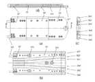
이러한 증기 발생기의 통상적인 구조가 도 1에 도시되어 있다.A typical structure of such a steam generator is shown in FIG.
도 1에는 1차 유체로부터의 열을 전달하여 2차 유체를 기화시키는 데 필요한 열 전달 표면을 형성하도록 U자형의 복수 개의 전열관(11)으로 이루어지는 관 다발(tube bundle, 12)을 포함하는 증기 발생기(10)가 도시되어 있다. 이 증기 발생기(10)는 수직으로 형성된 관형 쉘(14) 및 관형 쉘(14)의 하단부를 형성하는 반구형의 채널 헤드(20)를 갖는 용기로 이루어져 있다.1 shows a
관형 쉘(14)의 하부에는 제1 유체가 유통하여 외측의 제2 유체에 열을 전달하는 전열관(11)이 서로 밀집되어 배치되어 있는데, 전열관들(11)은 상하의 길이 방향으로 이격되어 배치되는 에그크레이트(Eggcrate)라 불리우는 지지판(15)을 관통하여 배치되어 관 다발(12)을 형성하고 있다.The
관 다발(12)과 관형 쉘(14)의 하부 사이에는 관 다발(12)을 둘러싸는 원통형의 금속제 슈라우드(13)가 배치되고, 지지판(15)이 이 슈라우드(13)에 용접되어 관 다발(12)이 지지되고 있다.A
관형 쉘(14)의 상부는 2차 유체로부터 수분을 제거하는 습분 분리기(19)가 배치되어 증기를 발전기 터빈(미도시)를 이송하는 부분을 형성하고 있다.The upper portion of the
관형 쉘(14)의 하부와 상부는 데크 패널(16)로 분리되며, 데크 패널(16)에는 복수의 개구(17)가 형성되고, 이 개구(17)에는 습분 분리기(15)에 2차 유체를 이송하는 복수의 라이저 튜브(18)가 결합되어 있다.A lower portion and an upper portion of the
관형 쉘(14)의 하단과 채널 헤드(20) 사이에는 튜브 시트(21)가 부착되는데, 이 튜브 시트(21)에는 복수 개의 개구(22)가 형성되어 이 개구에 관 다발(12)을 이루는 각각의 전열관(11)의 단부가 수용되어 있다.A
채널 헤드(20)는 분할판(23)에 의해 2개의 격실(24, 26)로 분리되는데, 일측의 격실(24)에는 1차 유체 입구(25)가 형성되어 있고, 다른 일측 격실(26)은 1차 유체의 출구(27)가 형성되어 있다.The
이러한 증기 발생기(10)에서 전열관(11)의 지지판(15)이 슈라우드(13)에 용접된 부분은 전열관(11)을 증기 발생기(10)에 고정하여 주는 부분으로서의 기능을 하므로, 이 용접부에 균열 또는 부식 등이 발생되는지 여부가 주기적으로 검사하여야 한다.The portion welded to the
도 2는 도 1에 도시한 유형의 증기 발생기에서 검사가 이루어져야 하는 용접부(151)를 나타내고 있다.FIG. 2 shows a
그러나, 데크 패널(16) 하측의 전열관(11)이 설치된 공간은 전열관(11)이 밀집되어 있고 용접부가 있는 슈라우드(13)와 지지판(15)의 외측면 사이는 20 mm 미만의 폭을 갖는 매우 좁은 공간이므로, 이 공간에 사람이 들어가서 검사 작업을 할 수 없다.However, the space in which the
따라서, 용접부를 검사하기 위해서는 사람이 관형 쉘(14)의 상부에 마련되는 통로(101)를 통하여 증기 발생기(10)의 상부로 진입한 후에 데크 패널(16)에 마련되어 있는 접근홀(161)을 덮는 접근홀 덮개(미도시)를 열고 접근홀(161)을 통하여 내시경과 같은 장비를 슈라우드(13)와 지지판(15) 사이에 삽입하여 검사 작업을 하여야 한다.Therefore, in order to inspect the welded portion, a person enters the upper portion of the
그러나, 원자력 발전소의 증기 발생기(10)는 높은 수준의 방사능을 함유하고 있어서 사람이 증기 발생기(10) 내의 공간에 장시간 잔류하면서 검사 작업을 할 수 없고, 특히 데크 패널(16) 하측의 전열관(11)이 설치된 공간은 매우 높은 수준의 방사능을 지닌 제1 유체가 유통하는 공간이므로, 접근홀(161)이 개방된 상태에서 사람이 내시경을 조작하는 경우에는 방사선 피폭량의 한도로 인하여 작업 시간이 매우 제한된다.However, since the
더욱이, 검사를 위해서는 데크 패널(16)의 접근홀(161)로부터 슈라우드(13)와 지지판(15) 사이의 공간으로 내시경과 같은 영상 장비를 내려 보내어 영상 장비가 용접부(151)에 근접하도록 하여야 하지만, 모든 용접부들(151)이 접근홀(161)의 바로 아래에 배치되어 있지 않아 영상 장비가 자중에 의해 내려가서 용접부에 근접할 수 없는 경우가 있고, 특히 아래쪽의 용접부(151)를 검사하려는 경우에는 위쪽의 용접부(151)에 의해 영상 장비의 이동이 막혀서 그 아래쪽의 용접부에 영상 장비가 근접할 수 없기 때문에 용접부에 대한 정확한 검사가 이루어지기 어렵다.Further, for the inspection, the video equipment such as the endoscope should be sent from the
또한, 증기 발생기의 상부 공간으로 진입할 수 있는 통로(101) 및 슈라우드(13)와 관 다발(12) 사이로 검사 장치를 투하할 수 있는 접근 홀(161)은 모두 400 mm 이하의 직경을 갖는 좁은 곳이므로, 이들 통로(101)와 접근 홀(161)을 통하여 큰 크기의 검사 장비를 투입하거나 많은 수의 작업자가 동시에 출입하기 곤란하다.
증기 발생기의 용접부를 검사하는 장비에 관한 종래 기술로서는 문헌 1의 특허공보 제10-0855117호 및 문헌 2의 공개특허공보 제10-2014-0044163호가 있다.The
As a conventional technique relating to an apparatus for inspecting a weld portion of a steam generator, Patent Document No. 10-0855117 of Document 1 and Patent Document No. 10-2014-0044163 of Document 2 are known.
본 발명은 전술한 문제점을 해결하고자 하는 것으로서, 증기 발생기에서 전열관의 관다발을 지지하는 지지판과 관 다발을 둘러싸는 슈라우드 사이의 용접부에 관한 검사 장치를 제공하려는 것으로서, 구체적으로는 검사용 영상 장비가 접근할 수 없는 위치에 배치된 용접부에 영상 장비를 접근시켜 검사를 수행할 수 있는 검사 장치를 제공하려는 것이다.An object of the present invention is to provide an inspection apparatus for a weld between a support plate supporting a tube bundle of a heat transfer tube and a shroud surrounding a tube bundle in a steam generator, And to provide an inspection apparatus capable of performing inspection by approaching a video equipment to a welded portion disposed at a position where it is impossible to perform inspection.
또한, 본 발명은 원자력 발전소의 증기 발생기에 검사 장치를 설치하고 영상 장비를 용접부에 근접시키는 작업을 할 때에 사람이 받는 방사능 피폭량을 최소한으로 할 수 있도록 영상 장비를 용접부에 근접시키는 작업을 증기 발생기의 외부 또는 방사능에의 노출이 최소한으로 되는 위치에서 원격으로 할 수 있는 구조의 검사 장치를 제공하려는 것이다.The present invention also relates to an apparatus and a method for installing a test apparatus in a steam generator of a nuclear power plant and moving an image device closer to a welded portion in order to minimize a radiation exposure to a human being. And to provide an inspection apparatus that can be remotely constructed from a position where exposure to external or radiation is minimized.
또한, 본 발명은 증기 발생기 상부 공간의 진입용 통로 및 상부 공간과 관 다발 사이의 공간으로 접근할 수 있는 접근 홀에 쉽게 투입될 수 있는 크기와 구조를 갖는 검사 장치를 제공하려는 것이다.It is another object of the present invention to provide an inspection apparatus having a size and structure that can be easily inserted into an access hole of an upper space of a steam generator and an access hole accessible to a space between an upper space and a tube bundle.
본 발명의 발명자들은 전술한 과제와 관련하여, 다음과 같은 기능을 갖춘 검사 장치를 고려하였다.The inventors of the present invention have considered an inspection apparatus having the following functions in connection with the above-described problems.
우선, 증기 발생기의 데크 패널에 마련된 접근홀로부터 중력을 이용하여 검사용 영상 장비를 용접부까지 내려 보내되 용접부가 접근홀의 중력 방향 수직 하방에 있지 않은 경우에 원격으로 영상 장비가 용접부로 근접할 수 있도록 하는 기능을 갖춘 검사 장치를 고려하였다.First, the video equipment for inspection is sent down to the welding part using gravity from the access hole provided in the deck panel of the steam generator, so that the video equipment can be remotely located near the welding part when the welding part is not vertically below the gravity direction of the approach hole. And the like.
또한, 검사용 영상 장비가 선단에 부착되어 슈라우드와 전열관의 지지판 사이의 좁은 폭의 공간을 따라 용접부까지 연장되어 검사용 영상 장비를 용접부에 근접시킬 수 있는 검사 장치를 고려하였다.Also, an inspection apparatus is proposed in which an inspection video device is attached to a front end and extends to a welded portion along a narrow space between a shroud and a supporting plate of a heat transfer pipe to bring the inspection video equipment close to the welded portion.
이러한 고려에 따라 안출된 본 발명은 증기 발생기의 전열관들을 지지하는 지지판이 전열관들의 관다발을 둘러싸는 슈라우드에 용접된 용접부를 검사하는 검사 장치에 관한 것으로서, 폭과 길이에 비해 두께가 얇은 패널 형태로 구성되고 그 내측에 길이방향으로 관통하는 복수 개의 통로가 형성되는 복수 개의 안내관을 포함하고, 이 복수 개의 안내관은 상기 용접부와 상기 검사 장치의 조작 위치 사이에서 서로 길이 방향으로 결합되어 연장되며, 각각의 상기 안내관은 상기 지지판과 상기 슈라우드를 마주보는 2개의 주면을 포함하고, 상기 주면들 사이의 간격은 상기 관다발과 상기 슈라우드 사이의 간격보다 작게 형성되어 상기 안내관의 두께를 이루며, 상기 복수 개의 안내관은 복수 개의 제1 안내관과 복수 개의 제2 안내관을 포함하되, 상기 제1 안내관들은 그 주면이 서로 평행하게 배치되는 상태로부터 서로 맞닿게 배치되는 상태를 향하여 회전 가능하게 서로 결합되고, 상기 제2 안내관들은 상기 주면들이 서로 평행한 상태로 그 길이 방향의 축선이 소정 각도를 이루도록 회전 가능하게 서로 결합되어 상기 제1 안내관들에 대하여 상기 용접부를 향하는 앞쪽에 배치되고, 상기 안내관들에 마련되는 상기 복수 개의 통로 중에서 상기 안내관들의 폭 방향 양측에 배치되는 2개의 통로 각각에는 상기 용접부 쪽의 선단에 배치되는 제2 안내관으로부터 상기 조작 위치 쪽의 말단의 제1 안내관을 관통하여 연장되는 와이어가 설치되어, 상기 조작 위치에서 상기 와이어 중의 어느 하나를 당김으로써 상기 제2 안내관들이 그 결합 부분을 중심으로 회전하여 상기 선단의 제2 안내관이 상기 용접부에 근접하여 배치되며, 상기 선단의 제2 안내관에는 상기 용접부를 모니터링하는 영상 장비가 부착되고 상기 영상 장비의 케이블이 상기 복수 개의 통로 중에서 어느 하나의 통로를 통하여 연장된다.According to the present invention, there is provided an inspection apparatus for inspecting a welded portion of a support plate supporting heat transfer tubes of a steam generator welded to a shroud surrounding a tube of heat transfer tubes, And a plurality of guide tubes extending in the longitudinal direction and having a plurality of passages formed therein, the plurality of guide tubes extending longitudinally coupled to each other between the welding portion and the operating position of the inspection apparatus, Wherein the guide tube includes two main surfaces facing the support plate and the shroud, wherein a distance between the main surfaces is smaller than an interval between the tube bundle and the shroud to form the thickness of the guide tube, Wherein the guide pipe includes a plurality of first guide pipes and a plurality of second guide pipes, The inner tubes are rotatably coupled to each other in such a manner that their inner surfaces are arranged to be in parallel with each other from a state in which they are arranged parallel to each other, And two passages disposed on both sides in the width direction of the guide pipes, respectively, of the plurality of passages provided in the guide pipes, A wire extending from a second guide tube disposed at a tip end of the welding portion toward the operating position and extending through a first guide pipe at an end thereof is provided so as to pull any one of the wires from the operating position, The guide tubes are rotated around the engaging portion so that the second guide tube at the tip is close to the welded portion W is placed, a second guide tube in the front end has been attached to a video equipment for monitoring the weld cable of the imaging device is extended through one of the passages of the plurality of passages.
이러한 구성을 갖는 본 발명의 검사 장치는, 얇고 긴 패널 형태의 복수 개의 안내관이 슈라우드와 지지판 사이의 폭이 좁은 공간을 통하여 용접부까지 연장될 수 있다.According to the inspection apparatus of the present invention having such a configuration, a plurality of guide pipes in the form of a thin and long panel can be extended to the welded portion through the narrow space between the shroud and the support plate.
안내관은 제1 및 제2의 2가지 유형의 안내관으로 구성되는데, 제1 안내관은 그 주면이 서로 평행한 상태로부터 주면끼리 맞닿는 방향으로 회전 가능하므로 좁은 작업 공간으로 안내관을 들여와서 슈라우드와 관 다발 사이의 공간으로 투입하고자 할 때, 안내관이 구부러진 상태에서 투입하고자 할 때, 제1 안내관들이 서로 각도를 이룬 상태로 투입될 수 있고, 슈라우드와 지지판 사이의 공간에서는 슈라우드의 내면에 맞추어 주면들이 서로 평행한 상태로 펼쳐져서 길게 연장될 수 있다.The guide pipe is composed of two types of guide pipes of first and second types. The first guide pipe is rotatable in a direction in which the main surfaces are in contact with each other from a state in which the main surfaces thereof are parallel to each other. The first guide pipes can be inserted at an angle to each other when the guide pipe is to be inserted into a space between the tube bundles and when the guide pipe is to be inserted in a bent state and in a space between the shroud and the support plate, The main surfaces can be extended in parallel with each other and extended long.
제2 안내관은 제1 안내관의 앞쪽에 배치되어 용접부에 근접하게 되는 것이다. 이 제2 안내관들은 그 주면들이 서로 평행한 상태로 그 길이 방향의 축선이 소정 각도를 이루도록 회전 가능하게 서로 결합되므로, 슈라우드와 지지판 사이의 공간에서 슈라우드의 내면에 맞추어 평행하게 된 상태에서 슈라우드의 표면을 따라 안내관들이 연장되는 길이 방향에 대해 서로 각도를 이루어 배치될 수 잇다.And the second guide pipe is disposed in front of the first guide pipe to come close to the welded portion. The second guide pipes are connected to each other so that their main surfaces are parallel to each other and are rotatably coupled with each other so that their axial axes are at a predetermined angle. Thus, in the space between the shroud and the support plate, parallel to the inner surface of the shroud, Can be arranged at an angle to each other with respect to the longitudinal direction along which the guide tubes extend along the surface.
따라서, 안내관들이 슈라우드와 관 다발 사이의 공간으로 투입되면서 제1 안내관들은 그 자중에 의해 아래쪽으로 길게 연장되어 직선을 이루게 되지만, 제1 안내관 앞쪽으로 배치되는 제2 안내관은 그 길이 방향에 대해 좌측 또는 우측으로 회전하여 안내관들이 하향하여 연장된 방향의 좌측 또는 우측에 배치되어 있는 용접부에 그 선단이 근접할 수 있게 된다.Therefore, while the guide tubes are inserted into the space between the shroud and the tube bundle, the first guide tubes are extended downward by their own weight to form a straight line. However, the second guide tube arranged in front of the first guide tube has its longitudinal direction The distal end of the guide tube can be brought close to the welded portion disposed on the left side or the right side in the direction in which the guide tubes extend downward.
안내관들에 마련되는 통로들에 설치되는 와이어를 조작함으로써 제2 안내관들이 회전할 수 있다.The second guide pipes can be rotated by operating the wires provided in the passages provided in the guide pipes.
용접부에 근접하게 되는 선단의 제2 안내관에 고정되어 말단의 제1 안내관을 관통하여 배치되는 한쌍의 와이어가 안내관들의 폭 방향 양측의 통로에 배치되므로, 말단의 제1 안내관을 관통한 위치에서 일측의 와이어의 단부를 당기면 선단의 제2 안내관이 폭 방향에 대하여 일측으로만 편중된 힘을 받게 되며, 이러한 편중된 힘에 의해 제2 안내관들은 당겨진 와이어 쪽으로 회전을 하게 되고, 제1 안내관은 회전하지 않는다.Since a pair of wires fixed to the second guide tube at the distal end which comes close to the welded portion and arranged through the first guide tube at the distal end are disposed in the passages on both sides in the width direction of the guide tubes, The second guide tube at the tip end receives a biased force only to one side with respect to the width direction and the biased force causes the second guide tubes to rotate toward the pulled wire, 1 The guide tube does not rotate.
따라서, 안내관들이 슈라우드와 지지판 사이의 공간으로 투입되어 자중에 의해 아래쪽으로 연장된 상태에서, 예컨대 검사하여야 할 용접부가 안내관들의 좌측에 있는 경우에는 좌측의 와이어를 당김으로써 제2 안내관들이 좌측으로 회전하여 선단의 안내관이 용접부에 근접하고, 그 선단의 제2 안내관에 부착된 영상 장비로 용접부를 검사할 수 있게 된다.Therefore, in the state where the guide pipes are inserted into the space between the shroud and the support plate and extend downward by their own weight, for example, when the welded portion to be inspected is on the left side of the guide pipes, by pulling the wire on the left side, So that the guide tube at the tip comes close to the weld, and the welded part can be inspected by the image equipment attached to the tip guide tube at the tip.
이상과 같은 본 발명의 검사 장치의 구성과 작용에 따르면, 예컨대 원자력 발전소의 증기 발생기에서 전열관의 관다발을 지지하는 지지판과 슈라우드의 용접부를 검사하는 경우, 검사 작업을 행하는 작업자들이 관다발이 설치된 공간의 상부에 진입하여 접근홀을 통하여 슈라우드와 지지판 사이의 매우 폭이 좁은 공간으로 안내관들을 투하하고, 말단의 제1 안내관을 관통하여 연장되는 한쌍의 와이어를 밀거나 당기는 동작에 의해 선단 측의 제2 안내관들이 회전하여 용접부에 근접하도록 배치하고 선단의 제2 안내관에 부착된 영상 장비를 통하여 용접부를 검사할 수 있다.According to the structure and operation of the inspection apparatus of the present invention as described above, for example, when inspecting the welded portion of the support plate and the shroud for supporting the tube bundle of the heat transfer tube in the steam generator of the nuclear power plant, , The guide tubes are dropped into a very narrow space between the shroud and the support plate through the access hole, and by pushing or pulling a pair of wires extending through the first guide tube at the distal end, It is possible to inspect the welded part through the image equipment attached to the second guide pipe at the tip.
따라서, 이러한 검사 작업은 용접부가 접근홀의 수직 하방에 배치되어 있지 않거나 다른 용접부에 의해 해당 용접부로의 접근이 곤란한 경우에도 와이어의 조작에 의해 영상 장비가 부착된 선단의 제2 안내관이 용접부에 근접하도록 하여 정확한 검사를 행할 수 있다.Therefore, even in the case where the welded portion is not disposed vertically below the approach hole or is difficult to access to the welded portion by the other welded portion, the second guideed tube at the tip to which the image equipment is attached by the operation of the wire is close to the welded portion So that accurate inspection can be performed.
또한, 안내관들을 투하한 후에 와이어의 조작에 의해 선단의 제2 안내관을 용접부에 근접시키는 작업이나 영상 장비에 의한 검사 작업을 증기 발생기 내부에서 행할 필요가 없고, 길게 연장되고 회전 가능한 안내관을 증기 발생기의 외부까지 연장하여 증기 발생기의 외부에서 해당 작업을 행할 수 있다.Further, it is not necessary to perform the operation of bringing the second guide pipe at the tip end to the welded portion by the operation of the wire after dropping the guide pipes, or the inspection work by the video equipment inside the steam generator, It is possible to extend to the outside of the steam generator and perform the operation outside the steam generator.
또한, 본 발명의 검사 장치는 길이가 길게 연장되고 서로 회전할 수 있는 안내관들이 결합되므로, 본 발명의 검사 장치를 좁은 통로를 통하여 증기 발생기의 내부 공간 및 슈라우드와 지지판 사이의 공간으로의 좁은 접근홀을 통하여 진입시킬 수 있다.Further, since the inspection apparatus of the present invention is connected to the guide pipes which are elongated in length and rotatable with each other, the inspection apparatus of the present invention is connected to the inside space of the steam generator and the space between the shroud and the support plate through the narrow passage Hole.
본 발명의 실시 양태의 하나로서, 상기 제1 안내관들의 길이 방향의 단부 사이에는 그 폭 방향에 평행한 축선을 따라 배치되는 제1 힌지가 마련되어, 이 제1 힌지에 의해 상기 제1 안내관들이 서로 결합되어 상기 제1 힌지를 중심으로 서로 회전 가능하고, 상기 제2 안내관들의 길이 방향의 단부 사이에는 그 주면에 수직인 방향에 평행한 축선을 따라 배치되는 제2 힌지가 마련되어 이 제2 힌지에 의해 상기 제2 안내관들이 서로 결합되어 상기 제2 힌지를 중심으로 서로 회전 가능하고, 상기 제1 안내관들 중에서 상기 제2 안내관과 결합되는 제1 안내관의 단부 및 상기 제2 안내관들 중에서 상기 제1 안내관과 결합되는 제2 안내관의 단부 사이에는 상기 제2 힌지가 마련되어 이들 제1 안내관과 제2 안내관은 상기 제2 힌지를 중심으로 서로 회전 가능한 것으로 구성할 수 있다.As one embodiment of the present invention, a first hinge is disposed between the longitudinal ends of the first guide tubes along an axis parallel to the width direction, and the first hinge guides the first guide tubes And a second hinge disposed between the longitudinal ends of the second guide pipes along an axis parallel to a direction perpendicular to the main surface of the second guide pipes, Wherein the second guide tubes are coupled to each other and are rotatable about each other about the second hinge, an end portion of the first guide tube coupled with the second guide tube among the first guide tubes, The second guide pipe and the second guide pipe are rotatable relative to each other about the second hinge, between the ends of the second guide pipe coupled with the first guide pipe It can generate.
이와 같이 안내관들의 단부 사이에 힌지를 마련하여 힌지들로 안내관들을 서로 결합함으로써 제1 안내관들과 제2 안내관들이 각각의 회전 방식으로 회전 가능하게 된다.Thus, the hinge is provided between the end portions of the guide pipes, and the guide pipes are coupled to each other by the hinges, so that the first guide pipes and the second guide pipes can be rotated by the respective rotation methods.
한편, 본 발명의 하나의 실시 양태로서, 와이어를 당기는 구성으로서, 본 발명의 검사 장치는 각각의 상기 와이어를 당기거나 당김을 해제하도록 구성되는 와이어 조작기를 더 포함하고, 상기 말단의 제1 안내관 단부로부터 상기 와이어 조작기까지 연장되는 안내 튜브를 포함하여, 상기 와이어는 상기 안내 튜브의 내측을 통하여 상기 말단의 제1 안내관 단부로부터 상기 와이어 조작기로 연장되도록 구성할 수 있다.On the other hand, as an embodiment of the present invention, as a configuration for pulling a wire, the inspection apparatus of the present invention further includes a wire manipulator configured to pull or pull out each of the wires, And a guide tube extending from the end to the wire manipulator, the wire being configured to extend from the first guide tube end of the distal end to the wire manipulator through the inside of the guide tube.
이러한 구성에서 안내 튜브가 와이어 조작기에 의해 와이어가 당겨지는 반력을 지지하기 때문에, 제2 안내관들을 회전시키는 와이어의 조작은 안내관들의 말단에서 행할 필요는 없고, 말단의 제1 안내관으로부터 이격된 안전한 조작 위치까지 와이어를 연장하고 조작 위치에서 와이어의 당김 및 당김 해제 조작을 함으로써 선단의 제1 안내관이 용접부에 근접하게 하는 작업을 행할 수 있다.In this configuration, since the guide tube supports the reaction force to pull the wire by the wire manipulator, the operation of the wire rotating the second guide tubes need not be done at the end of the guide tubes, The wire can be extended to the safe operating position and the wire can be pulled and pulled off at the operating position to bring the first guide pipe at the tip closer to the welded portion.
또한, 본 발명의 추가의 실시 양태에 따르면, 상기 선단의 제2 안내관에는 상기 용접부를 세정하는 세정 노즐이 더 부착되고, 상기 세정 노즐에 압축 공기 또는 세정액을 공급하는 세정 호스가 상기 복수 개의 통로 중에서 어느 하나의 통로를 통하여 연장될 수 있다.According to a further embodiment of the present invention, a cleaning nozzle for cleaning the welded portion is further attached to the second guide pipe at the tip end, and a cleaning hose for supplying compressed air or a cleaning liquid to the cleaning nozzle is attached to the plurality of passages Through one of the passages.
본 발명의 검사 장치는 용접부의 균열이나 부식 등을 검사하는 것을 주용도로 하지만, 이러한 용도에 더하여 용접부에 부착된 이물질을 제거하도록 구성되는 것이 바람직하다.It is preferable that the inspection apparatus of the present invention is configured to remove foreign matter adhering to the welded portion in addition to such use, although it is a principal use to inspect cracks and corrosion of the welded portion.
본 발명에 따른 검사 장치는 슈라우드와 지지판 사이의 폭이 좁은 공간에 배치되어야 하므로 두께가 얇은 안내관으로 구성되지만, 안내관의 폭은 그 두께에 비해 제한적이지 않다.The inspection apparatus according to the present invention is constituted by a thin guide tube because the tube should be disposed in a narrow space between the shroud and the support plate, but the width of the guide tube is not limited by its thickness.
따라서, 안내관의 폭에 걸쳐 복수 개의 통로를 형성하고 그 통로 중의 하나를 통하여 선단의 안내관으로 세정액이나 공기와 같은 세정용 유체를 공급하고 선단의 안내관에 노즐을 부착하여 노즐로부터 용접부에 세정용 유체를 분사하도록 할 수 있다.Therefore, a plurality of passages are formed over the width of the guide tube, and a cleaning fluid such as a cleaning liquid or air is supplied to the guide pipe at the end through one of the passages, and a nozzle is attached to the guide pipe at the end, So that the fluid can be sprayed.
본 발명의 추가의 특징으로서, 본 발명의 검사 장치에서 상기 안내관의 주면 중에서 상기 슈라우드를 마주보는 주면에는 상기 안내관이 상기 슈라우드에 밀착하면서 이동할 수 있도록 회전 가능한 자석이 부착될 수 있다.As a further feature of the present invention, in the inspection apparatus of the present invention, a rotatable magnet may be attached to a main surface of the guide pipe facing the shroud, so that the guide pipe can move while closely contacting the shroud.
본 발명의 검사 장치에서 안내관들은 그 자중에 의해 슈라우드와 지지판 사이의 공간에서 수직 하방으로 이동하고 와이어의 조작에 의해 선단의 제2 안내관이 용접부 쪽으로 접근한다.In the inspection apparatus of the present invention, the guide tubes move vertically downward in the space between the shroud and the support plate by their own weight, and the second guide tubes at the tip approach the welded portion by the operation of the wire.
이러한 과정에서 안내관들은 자석에 의해 슈라우드에 밀착된 상태에서 이동할 수 있게 된다.In this process, the guide tubes can move with the magnets in close contact with the shroud.
또한, 자석에 관한 구체적인 구성으로서, 상기 안내관 중에서 상기 제1 안내관에는 상기 안내관의 길이 방향을 따라 회전 가능한 원통형의 자석이 부착되고, 상기 제2 안내관에는 구형의 자석이 부착될 수 있다.In addition, as a concrete configuration relating to the magnet, a cylindrical magnet that can rotate along the longitudinal direction of the guide tube is attached to the first guide tube of the guide tube, and a spherical magnet may be attached to the second guide tube .
와이어를 조작하여 제2 안내관이 용접부 쪽으로 회전할 때, 제1 안내관의 자석은 원통형으로 구성되어 길이 방향으로 회전하므로, 그 회전 방향이 아닌 방향으로의 힘에 대해서는 반력을 제공하게 된다.When the second guide tube rotates toward the welded portion by manipulating the wire, the magnet of the first guide tube is formed in a cylindrical shape and rotates in the longitudinal direction, so that a reaction force is applied to a force in a direction other than the rotational direction.
따라서, 제2 안내관이 회전하는 데 따른 힘이 제1 안내관에 작용할 때, 제1 안내관 주면은 원통형의 자석에 의해 제2 안내관의 회전에 따라 미끄러지거나 하지 않고 제 자리를 유지할 수 있다.Therefore, when the force generated by the rotation of the second guide tube acts on the first guide tube, the first guide tube main surface can be held in place by the cylindrical magnet, without sliding along with rotation of the second guide tube .
또한, 제2 안내관은 구형의 자석에 의해 슈라우드의 표면에 밀착되면서도 자석이 어느 방향으로도 자유롭게 회전하므로 용접부 쪽으로 회전하는 데 장애가 발생하지 않는다.Further, since the second guide tube is in close contact with the surface of the shroud by the spherical magnet, the magnet freely rotates in any direction, so that the obstacle to rotation toward the welded portion does not occur.
본 발명의 추가의 실시 양태로서, 증기 발생기에서 전열관이 설치되는 부분과 그 상부를 구획하는 데크 패널에 형성된 접근홀에 배치되는 홀더로서, 상기 안내관이 통과하여 낙하하며 안내관의 길이 방향에 수직한 단면 형상에 상응하는 안내 통로를 갖추고 상기 안내관을 클램핑하여 안내판의 추락을 방지하는 클램프를 갖추고, 상기 클램프의 높이 및 평면 상에서의 위치를 조정하는 수단을 갖춘 홀더를 더 포함할 수 있다.As a further embodiment of the present invention, there is provided a holder disposed in an approach hole formed in a deck panel for partitioning a portion where a heat transfer tube is installed in an upper portion of a steam generator, and a holder vertically A holder provided with a clamp having a guide passage corresponding to a cross-sectional shape and clamping the guide tube to prevent the guide plate from falling, and a means for adjusting the height and the position of the clamp on the plane.
이러한 홀더의 구성은 본 발명의 검사 장치를 설치하는 작업을 원할하게 해준다.The configuration of such a holder makes it easy to install the inspection apparatus of the present invention.
안내관들을 슈라우드와 지지판 사이의 공간에서 용접부를 향하여 낙하시키는 작업에서 홀더의 안내 통로는 안내관의 투하 위치를 정하게 해주고, 안내관을 클램프에 의해 고정한 후에 클램프의 높이 및 평면 상에서의 위치를 조정함으로써 정확한 투하 위치의 조정이 가능하게 된다.In the operation of dropping the guide tubes from the space between the shroud and the support plate toward the welded portion, the guide passage of the holder fixes the position of the guide tube to be discharged, fixes the guide tube by clamping and then adjusts the height of the clamp and the position on the plane It is possible to adjust the exact drop position.
도 1 및 도 2는 원자력 발전소에 설치되는 통상적인 증기 발생기의 구조를 개략적으로 보여주는 부분 파단 사시도이고,
도 3은 본 발명의 일 실시예의 안내관들이 용접부에 근접한 상태를 보여주는 도면이며,
도 4는 본 발명의 일 실시예의 제1 안내관들이 서로 결합된 상태를 보여주는 도면이고,
도 5 및 도 6은 도 4에 도시된 제1 안내관 중 하나를 나타내는 도면이며,
도 7은 본 발명의 일 실시예의 제2 안내관들이 서로 결합된 상태를 보여주는 도면이고,
도 8 및 도 9는 도 7에 도시된 제2 안내관 중 하나를 나타내는 도면이며,
도 10은 본 발명의 일 실시예의 제1 안내관으로부터 연장되는 와이어 및 케이블을 보여주는 도면이고,
도 11은 본 발명의 일 실시예의 홀더를 나타내는 도면이며,
도 12는 본 발명의 일 실시예의 안내관들이 홀더를 통하여 투하되는 상태를 보여주는 도면이다.1 and 2 are partially broken perspective views schematically showing a structure of a conventional steam generator installed in a nuclear power plant,
FIG. 3 is a view showing a state where the guide tubes of the embodiment of the present invention are close to the welded portion,
FIG. 4 is a view showing a state where first guide tubes of an embodiment of the present invention are coupled to each other,
Figs. 5 and 6 are views showing one of the first guide tubes shown in Fig. 4,
7 is a view showing a state where the second guide tubes of the embodiment of the present invention are coupled to each other,
Figs. 8 and 9 are views showing one of the second guide tubes shown in Fig. 7,
Figure 10 is a view showing wires and cables extending from a first guide tube of an embodiment of the present invention,
11 is a view showing a holder of an embodiment of the present invention,
12 is a view showing a state in which guide tubes of an embodiment of the present invention are dropped through a holder.
이하, 도면을 참조하여 본 발명의 바람직한 실시예를 설명한다.Hereinafter, preferred embodiments of the present invention will be described with reference to the drawings.
이하에서는 본 실시예의 절단 장치가, 도 1 및 도 2에 도시한 것과 같은 유형의, 원자력 발전소에 설치되는 증기 발생기에서 슈라우드(13)와 전열관(11)의 지지판(15) 사이의 용접부를 검사하는 데에 사용되는 실시예를 설명한다.Hereinafter, the cutting apparatus of the present embodiment inspects the weld between the
도 2를 참조하여, 본 발명의 검사 장치가 설치되고 검사 작업을 실시하는 위치를 설명한다.Referring to Fig. 2, the position where the inspection apparatus of the present invention is installed and the inspection work is performed will be described.
도 2에서 작업자와 본 실시예의 검사 장치가 통로(101)를 통하여 데크 패널(16) 위로 진입하고, 데크 패널(16)에 형성한 접근 홀(161)을 통하여 슈라우드(13)와 지지판(15) 사이의 공간으로 투입된다.2, the operator and the inspection apparatus of the present embodiment enter the
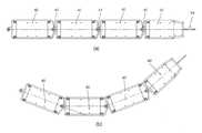
도 3을 참조하면, 본 실시예의 검사 장치의 제1 안내관들(30, 30, 30")과 제2 안내관들(40, 40')이 관 다발(12)의 아래를 향하여 길게 연장되어 선단의 제2 안내관(40')이 용접부(151)에 근접한 상태가 도시되어 있다. 안내관들(30, 30, 30", 40, 40')은 데크 패널(16)의 접근홀(161)을 통하여 투입되어 접근홀(161)로부터 용접부(151)까지 연장되어 있다.3, the
제1 안내관(30, 30', 30)이 도 4 내지 도 6에 도시되어 있다. 도 4는 제1 안내관들(30)이 서로 결합되어 있는 상태를 나타내고 있고, 도 5는 1개의 제1 안내관(30)을 도시하고 있고, 도 6은 제1 안내관들 중에서 선단 측의 제1 안내관(30')을 도시하고 있다.The
먼저, 도 4를 참조하면, 제1 안내관들(30, 30', 30")은 길게 연장된 패널 형태로 구성되고 그 길이 방향 단부 사이에서 폭 방향의 축선을 중심으로 회전 가능한 제1 힌지(31)로 서로 결합되어 연장되어 있다.4, the
도면에서 좌측에 배치되어 있는 제1 안내관(30')은 다른 제1 안내관들(30)과 달리 일 단부에 그 주면에 수직 방향으로 형성되는 제2 힌지홀(331')가 마련되어, 도 7에 도시하는 제2 안내관(40)과 결합된다. 또한, 도면에서 오른쪽에 배치되어 있는 제1 안내관(30")은 제1 안내관(30)의 종단을 형성하여, 이 제1 안내관(30")을 관통한 와이어나 케이블 등이 그 조작 장치나 전원 또는 제어 장치 등에 연결된다.The first guide pipe 30 'disposed on the left side in the drawing is provided with a second hinge hole 331' formed at one end thereof in a direction perpendicular to the main surface thereof, unlike the
도 5에는 1개의 제1 안내관(30)이 도시되어 있다. (a)는 평면도, (b)는 상면 패널이 제거된 상태의 평면도, (c)는 측면도를 도시하고 있다.In Fig. 5, one
제1 안내관(30)은 길이 방향 양측의 힌지 패널(32, 33))과 이들 사이의 상면패널(34)과 하면 패널(35)이 결합되어 두께가 얇고 길이가 긴 패널 형태로 형성되어 있다.The
측면도 및 상면 패널(34)이 제거된 상태의 평면도 (b)를 참조하면, 제1 안내관(30)의 내측에는 그 길이 방향으로 6개의 통로(361 ~366)가 관통하여 형성되어 있는데, 폭 방향 양측의 통로(361, 366)로는 제2 안내관들(40)을 회전시키는 와이어가 통과하고 나머지 통로(362 ~ 365)로는 조명 전원 케이블, 내시경, 카메라 케이블 및 세정 호스가 관통한다.Referring to the side view and the plan view (b) of the state in which the
또한, 하면 패널(35)의 폭 방향 좌우로는 원통형의 자석들(351)이 그 축선을 제1 안내관(30)의 폭방향과 평행하게 한 상태로 길이 방향으로 열을 지어 간격을 두고 부착되어 있다. 이들 자석들(351)은 증기 발생기의 슈라우드(13)의 내측 표면에 밀착되어 제1 안내관(30)의 이동을 안내한다.In the width direction of the
힌지 패널(32, 33)에는 제1 힌지(31)를 이루는 힌지 블록(321, 331)이 폭 방향 양측으로 부착되어 있고, 일측의 힌지 블록들(331)에는 힌지핀(332)이 결합되어 있고, 다른 측의 힌지 블록들(321)에는 힌지핀(332)이 삽입되어 결합되는 홀이 형성되어 있다.Hinge blocks 321 and 331 constituting a
이와 같은 구성에 의해 힌지 블록(331)의 힌지핀(332)이 다른 제1 안내관(30, 30', 30")의 힌지 블록(321)에 결합됨으로써 제1 안내관들(30, 30', 30")이 서로 결합되어, 제1 안내관(30, 30', 30")이 그 폭방향의 축선을 중심으로, 즉 그 주면이 서로 평행한 상태와 서로 맞닿는 상태 사이에서 회전할 수 있게 된다.The
도 6에는 제2 안내관(40)과 결합되는 선단 측의 제1 안내관(30')이 도시되어 있다. (a)는 평면도, (b)는 상면 패널(34')이 제거된 상태의 평면도, (c)는 측면도 및 (d)는 A-A선에 따른 단면도를 도시하고 있다.FIG. 6 shows a first guide tube 30 'at the distal end side coupled with the
선단 측의 제1 안내관(30')은 제2 안내관(40)과 결합되기 위한 구성에서 다른 제1 안내관(30)과 차이가 있다.The first guide tube 30 'on the distal end side is different from the
다른 제1 안내관(30)과 결합되는 힌지 패널(32')의 구성은 다른 제1 안내관(30)의 힌지 패널(32)의 구성과 차이가 없지만, 제2 안내관(40)과 결합되는 힌지 패널(33')은 그 길이 방향 단부에서 폭 방향의 중앙이 돌출되어 폭 방향의 양단을 향하여 경사진 면이 형성되어 있고, 그 돌출된 중앙에는 제2 안내관(40)과 제2 힌지(41)를 형성하는 힌지홀(331')이 형성되어 있다.The structure of the hinge panel 32 'coupled with the other
또한, 도 6의 (b)에서 보듯이, 힌지홀(331')과의 간섭을 피하기 위하여 내측의 4개의 통로(362', 363', 364', 365')가 좌우로 벌어져 배치되고, 그 사이에 원통형의 자석(351)이 배치되어 있다.6 (b), four inner passages 362 ', 363', 364 ', and 365' are disposed so as to extend to the left and right in order to avoid interference with the hinge holes 331 ' And a
다음으로 도 7 내지 도 9를 참조하여 제2 안내관(40, 40')의 구성을 설명한다.Next, the construction of the
도 7은 제2 안내관들(40, 40')이 서로 결합되어 있는 상태를 나타내고 있고, 도 8은 1개의 제2 안내관(40)을 도시하고 있고, 도 9는 제2 안내관들 중에서 선단 측의 제2 안내관(40')을 도시하고 있다.FIG. 7 shows a state in which the
먼저, 도 7를 참조하면, 제2 안내관들(40, 40')은 길게 연장된 패널 형태로 구성되는데, 제2 안내관들(40)은 그 길이 방향 단부 사이에 마련되는 제2 힌지(41)에 의해 서로 결합되어 이 제2 힌지(41)를 중심으로 회전 가능하게 구성되어 있다.Referring to FIG. 7, the
제2 힌지(41)는 제2 안내관(40, 40')의 주면, 즉, 폭과 길이에 의해 정해지는 표면들에 수직한 방향으로 회전하도록 구성되어, 제2 안내관(40, 40')의 주면들이 서로 평행한 상태로 유지되는 상태에서 그 길이 방향의 축선이 소정 각도를 이루도록 회전할 수 있다.The
선단의 제2 안내관(40')은 일측 단부만 제2 힌지(41)에 의해 다른 제2 안내관(40)과 결합되고, 그 선단에는 용접부(151)를 검사하기 위한 내시경(54)이 돌출되어 있다.Only one end of the
도 8을 참조하여, 제2 안내관(40)의 구성에 대해 구체적으로 설명한다.The configuration of the
도 8에서 (a)는 평면도, (b)는 상면 패널이 제거된 상태의 평면도, (c)는 측면도, (d)는 A-A선에 따른 단면도를 도시하고 있다.FIG. 8A is a plan view, FIG. 8B is a plan view with the top panel removed, FIG. 8C is a side view, and FIG. 8D is a sectional view taken along the line A-A.
제2 안내관(40)은 길이 방향 양측의 힌지 패널(42, 43)과 이들 사이의 상면패널(44)과 하면 패널(45)이 결합되어 두께가 얇고 길이가 긴 패널 형태로 형성되어 있다.The
측면도 및 상면 패널(44)이 제거된 상태의 평면도 (b)를 참조하면, 제2 안내관(40)의 내측에는 그 길이 방향으로 6개의 통로(461 ~ 466)가 관통하여 형성되어 있는데, 폭 방향 양측의 통로(461, 466)로는 제2 안내관들(40)을 회전시키는 와이어가 통과하고 나머지 통로(462 ~ 465)로는 조명 전원 케이블, 내시경, 카메라 케이블 및 세정 호스가 관통한다.Referring to the side view and the plan view (b) of the state in which the
또한, 하면 패널(45)의 폭 방향 좌우로는 구형의 자석들(451)이 제2 안내관(40)의 폭 방향 양측으로 열을 지어 간격을 두고 부착되어 있다. 이들 자석들(451)은 증기 발생기의 슈라우드(13)의 내측 표면에 밀착되어 제2 안내관(40)의 길이 방향 이동 및 회전을 가이드한다.
일측의 힌지 패널(42)은 그 길이 방향 단부가 제2 안내관(40)의 길이 방향에 대해 수직으로 형성되어 있고, 여기로부터 힌지홀(412)이 형성된 힌지부(411)가 돌출되어 형성되어 있고, 다른 쪽의 힌지 패널(43)은 그 길이 방향 단부에서 폭 방향의 중앙이 돌출되어 힌지핀(413)이 부착되어 있고, 그 중앙으로부터 폭 방향 양측으로 경사진 표면이 형성되어 있다.The
이와 같은 구성에 의해 힌지 패널(43)의 힌지핀(413)이 다른 제2 안내관(40, 40')의 힌지부(411)의 힌지홀(412)에 삽입되어 결합됨으로써 제2 안내관들(40, 40')이 서로 결합되어, 제2 안내관들(40, 40')이 힌지핀(413)을 중심으로 회전할 수 있게 되어 있다.The
도 7의 (b)는 그러한 회전 상태의 일례를 보여주고 있다. 이 도면에서 보면, 제2 안내관들(40, 40')은 제2 힌지(41)를 중심으로 서로 회전함으로써, 길이 방향 축선이 서로 일정 각도로 어긋나게 된다. 이러한 회전에 의해 제2 안내관(40)의 단부 표면이 경사진 단부 패널(43)은 다른 제2 안내관(40)의 반대측 단부 패널(42)과 맞닿게 되면 그 회전이 저지된다. 즉, 단부 패널(43)의 길이 방향 단부 표면의 경사진 표면의 경사각은 제2 안내관(40)의 회전 각도 범위를 제한하는 기능을 한다.Fig. 7 (b) shows an example of such a rotation state. In this figure, the
도 9에는 제2 안내관(40, 40') 중에서 그 선단에 부착되는 제2 안내관(40')이 도시되어 있다. (a)는 평면도, (b)는 상면 패널(44')이 제거된 상태의 평면도, (c)는 측면도, (d)는 단면도를 나타내고 있다.9 shows a
선단의 제2 안내관(40')은 일측 단부에서 다른 제2 안내관(40)과 결합되어 있지만, 선단 측의 단부는 다른 안내관과 결합되지 않고 용접부(151)를 검사하기 위한 각종 장치들이 장착되어 있다는 점에서 다른 제2 안내관(40)의 구성과 차이가 있다.Although the
제2 안내관들을 회전시키는 와이어는 선단의 제2 안내관(40')을 관통하지 않고 그 말단에 고정되어 부착되며, 제2 안내관(40')의 내측으로는 4개의 통로(462 ~ 465)가 형성되고, 각각의 통로에는 내시경, 카메라 케이블, 조명용 케이블, 세정 호스 등이 관통하게 되어 있고, 그 선단에는 내시경(54), 카메라(472), LED 조명(473) 및 세정 노즐(474)이 장착되어 있다.The wire for rotating the second guide tubes is fixedly attached to the distal end of the
이상의 구성을 갖는 제1 안내관들(30,30',30")과 제2 안내관들(40, 40')은 용접부(151)에 근접하는 선단의 제2 안내관(40), 복수 개의 제2 안내관들(40), 제2 안내관과 결합되는 제1 안내관(30), 복수 개의 제1 안내관들(30) 및 종단의 제1 안내관(30")이 순차로 결합되어 있다.The
제2 안내관들(40, 40')이 용접부(151)를 향하도록 회전시키는 와이어 및 선단의 제2 안내관에 부착되는 내시경(54), 카메라(472), 조명용 LED(473) 및 세정 노즐(474)과 연결되는 케이블과 전원선 및 호스 등은 제1 및 제2 안내관들의 통로(361 ~ 366, 461 ~ 466)을 따라 선단의 제2 안내관(40')으로부터 말단의 제1 안내관(30")까지 연장되고, 도 10에 도시된 바와 같이, 말단의 제1 안내관(30")을 관통하여 후방으로 연장된다.A
도 10에 도시한 바와 같이, 와이어(51), 조명 케이블(53), 내시경(54), 세정 호스(55) 및 카메라 케이블(56)이 제1 안내관(30)을 통과하고 말단의 제1 안내관(30")을 통하여 연장되어 도시하지 않은 전원, 세정액 펌프, 모니터 등으로 연결되어 있다.10, the
제1 안내관(30, 30")의 폭방향 양측으로 통과하는 와이어(51)는 말단의 제1 안내관(30")으로부터 이 와이어(51)를 당기거나 당김을 해제하는 와이어 조작기(50)로 연결되는데, 제1 안내관(30")의 말단과 조작기(50) 사이에는 안내 튜브(52)가 배치되어 있고, 와이어(51)는 안내 튜브(52)를 통하여 와이어 조작기(50)로 연장되어 있다.The
와이어 조작기(50)는 와이어(51)의 단부가 고정된 당김 볼트(501)가 그 단부에 마련되어, 이 당김 볼트(501)를 일측으로 회전시키면 당김 볼트(501)가 와이어 조작기(50)의 본체로부터 멀어지면서 와이어(51)를 당기고 반대측으로 회전시키면 해제되도록 구성되어 있다. 이러한 당김 볼트(501)의 머리부에 핸들을 결합하여 핸들로 조작이 이루어지도록 구성할 수도 있다.The
이상과 같은 구성에 따라, 선단에 검사용 내시경 등을 장착한 제2 안내관(40')은 다른 제2 안내관(40) 및 제1 안내관들(30, 30, 30")과 함께 증기 발생기(10)의 데크 패널(16)에 형성한 접근홀(161)로부터 수직 하방으로 투하되어 용접부(151)의 근방의 위치까지 도달하게 된다.According to the above-described configuration, the
예컨대, 도 3에 도시한 바와 같이, 용접부(151)가 안내관들의 투하 위치로부터 좌측에 있을 때, 작업자가 와이어 조작기(50)의 일측의 당김 볼트(501)가 인출되도록 회전시킴으로써 와이어(51)가 당겨지면 제2 안내관들(40, 40')이 그 결합부인 제2 힌지(41)를 중심으로 회전하여 선단의 제2 안내관(40')이 용접부(151)에 근접하게 된다.3, when the welded
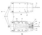
한편, 안내관들은 데크 패널(16)의 접근홀(161)로 투하될 때, 그 투하 위치가 조절되어 고정되는 것이 바람직한데, 도 11에는 투하되는 안내관들을 가이드하고 투하가 완료된 안내관들을 제 위치에 고정시켜주는 홀더(60)가 도시되어 있다.11, it is preferable to guide the guide tubes to be dropped, and to guide the guide tubes that have been dropped into the access holes 161 of the
도 11에서 (a)는 평면도이고 (b)는 A-A선에 따른 단면도이다.11 (a) is a plan view and (b) is a sectional view taken along line A-A.
도 11을 참조하여 홀더(60)의 기능별로 그 구성을 설명한다. 홀더(60)는 5개의 기능을 하는 부분으로 구성되어 있다.The structure of the
첫 번째로, 홀더(60)가 접근홀(161)에 놓여 고정되도록 하는 구성으로서, 가운데에 정사각형의 공간을 형성하는 4개의 커버 플레이트(611, 612)가 접근홀(161)을 덮는 형태로 놓여 있다.First, four
서로 대향하는 2개의 커버 플레이트(611)에는 접근홀(161)이 모서리에 결합되는 결합 블록(613)과 이 결합 블록을 회전시키는 레버(614)가 마련되어 있다.The two
두 번째로, 안내관들의 일측 방향의 위치를 조정하는 구성으로서, 커버 플레이트(611)의 양 단부에는 각각 X축 로드(62)가 커버 플레이트(611) 사이에 걸쳐 설치되어 있고, X축 로드(62)에는 각각 X축 이동 블록(63)이 X축 로드(62)를 따라 이동할 수 있게 마련되어 있다. 하나의 X축 이동 블록(63)에는 이것의 이동을 방지하는 고정 핸들(631)이 마련되어 있다.The
세 번째로, 안내관들의 X축 방향과 수직인 Y 축 방향의 위치를 조정하는 구성으로서, X축 이동 블록(63)의 양 단부에는 각각 Y축 로드(64)가 X축 이동 블록(63) 사이에 걸쳐 설치되어 있고, 여기에는 하나의 Y축 이동 블록(65)이 Y축 로드들(64)을 따라 Y축으로 이동 가능하게 마련되어 있다. Y축 이동 블록(65)에는 그 이동을 방지하는 고정 핸들(651)이 마련되어 있다.A Y-
네 번째로, 안내관들의 높이를 미세 조정하는 구성이 마련되어 있다.Fourth, there is provided a configuration for finely adjusting the height of the guide pipes.
Y축 이동 블록(65)의 네 모서리에는 위쪽으로 연장되는 Z축 로드(66)가 마련되어 있다. Z축 로드(66)의 상단에는 Y축 이동 블록(65)과 평행하게 배치되는 Z축 로드 브래킷(67)이 마련되어 있다. Y축 이동 블록(65)과 Z축 로드 브래킷(67) 사이에는 스크류 축(68)이 설치되어 있다.A Z-
또한, Y축 이동 블록(65)과 Z축 로드 브래킷(67) 사이에는 이것들과 평행하게 놓이는 클램프 브래킷(69)이 배치되어 있는데, 이 클램프 브래킷(69)은 Z축 로드(66)에 의해 가이드 되어 상하로 이동 가능하게 되어 있고, 스크류 축(68)이 맞물리면서 관통하고 있다. 따라서, 스크류 축(68)을 회전시키면 클램프 브래킷(69)은 Z축, 즉 상하로 이동한다.A
다섯 번째로, 안내관들의 투입을 가이드하고 고정하는 구성이 마련되어 있다.Fifth, there is provided a configuration for guiding and fixing the introduction of the guide pipes.
Y축 이동 블록(65)과 클램프 브래킷(69) 및 Z축 로드 브래킷(67)의 중앙에는 안내관들이 지나갈 수 있는 관통홀(651, 691, 671)이 각각 형성되어 있고, 클램프 브래킷(69)에는 클램프축(692)이 나사 결합되는 상태로 관통하는 클램프 블록(693)이 마련되어 있다.Through
이러한 구성에 따라, 관통홀(651, 691, 671)을 통하여 선단의 제2 안내관(40')부터 안내관들을 순차로 통과시켜 투하하고, 투하가 완료되어 선단의 제2 안내관(40')이 검사 대상인 용접부(151)의 근처에 도달한 후에는 클램프축(692)을 회전시켜 그 선단이 클램프 블록(693)을 지나 관통홀(691)에 놓인 제1 안내관(30)을 눌러서 클램프 브래킷(69)에 고정되게 한다.According to this configuration, the guide pipes are sequentially passed through the through-
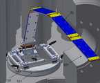
데크 패널(16)의 접근홀(161)에 장착된 홀더(60)를 통하여 안내관들(30, 40)을 슈라우드(13)와 지지판(15) 사이의 공간에 투입하는 상태가 도 12에 도시되어 있다.The state in which the
제1 안내관들(40, 40')과 제2 안내관들(30, 30', 30")은 서로 길이 방향으로 결합되어 적어도 증기 발생기(10)의 데크 패널(16)로부터 용접부(151)까지 길게 연정되는 것이므로, 이것이 증기 발생기(10) 상부의 통로(101)를 통하여 내부로 운반되고 데크 패널(16)의 접근홀(161)로부터 홀더(60)를 통하여 투입되기 위해서, 도 12에 도시한 바와 같이 대부분의 길이를 차지하는 제1 안내관들(30)이 서로에 대해 회전하여 접히는 방향으로 굴곡되면서 홀더(60)의 관통홀((651, 691, 671)을 통하여 투입된다.The
투입 시에 안내관들은 슈라우드(13)와 지지판(15) 사이의 공간에서 그 중량에 의해 낙하하여 용접부(151)에 가장 가까운 위치로 투하되어야 하므로, 홀더(60)에서 X축 이동 블록(63)과 Y축 이동 블록(65)의 위치를 조정하여 그 투입 위치를 맞출 수 있다.The guide tubes are dropped from the space between the
투입 위치를 맞추어 안내관들을 투입하여 선단의 제2 안내관(40')이 용접부(151)의 근처에 도달하면, 클램프축(692)을 회전시켜 제1 안내관(30)을 클램프 브래킷(69)에 고정한다.When the
고정 후에는 스크류 축(68)을 회전시켜 클램프 브래킷(69)의 높이를 조정함으로써 선단의 제2 안내관(40')의 높이를 용접부(151)의 높이에 맞출 수 있다.The height of the
이어서, 와이어 조작기(50)를 조작하여 어느 일측의 와이어(51)를 당기면 와이어가 당겨진 방향으로 제2 안내관들(40, 40')이 제2 힌지부(41)를 중심으로 회전함으로써 제2 안내관들(40, 40')이 용접부(151)를 향하여 회전하여 선단의 제2 안내관(40')이 용접부(151)에 근접한다.When the
이와 같은 본 실시예의 검사 장치의 설치 과정에 있어서, 슈라우드(13)와 관 다발(12) 사이의 공간은 외부로부터의 빛이 차단되어 어둡지만, 선단의 제2 안내관(40')에 마련되어 있는 LED 조명(473)과 카메라(472)에 의해 진행 방향 앞쪽이 촬영되고, 촬영되는 영상은 안내관들의 통로로 연장되어 있는 카메라 케이블(도 10의 56)을 통하여 모니터(미도시)로 전송되어 작업자가 이를 확인하면서 안내관들(30, 40)을 투입하고 선단의 제2 안내관(40')이 용접부(151)에 근접하게 할 수 있다.The space between the
선단의 제2 안내관(40')이 용접부(151)에 근접한 후에는 내시경(54)을 통하여 용접부(151)를 관찰하여 결함이나 균열 또는 부식 등의 유무를 검사한다.After the tip of the
검사 중에 용접부(151)에 이물질 등이 부착된 것을 확인한 경우에는 선단의 제2 안내관(40')에 마련된 세정 노즐(474)을 통하여 세정 호스(55)를 통하여 공급되는 세정액 또는 압축 공기로 이물질을 제거할 수 있다.If it is confirmed that the foreign matter adheres to the welded
하나의 용접부(151)에 대한 검사 및 세정 작업이 완료되면 와이어 조작기(50)로 선단의 제2 안내관(40')의 위치를 변경하여 반대측의 용접부를 검사하거나, 안내관들을 끌어올리거나 더 내려서 다른 용접부에 대한 검사 작업을 진행한다.When the inspection and cleaning operation for one
이상, 본 발명의 검사 장치에 대하여 원자력 발전소의 증기 발생기에 적용한 실시예를 설명하였다. 그러나, 본 발명의 검사 장치는 원자력 발전소의 증기 발생기에만 이용될 수 있는 것은 아니고, 검사하려는 용접부에 사람이 직접 접근할 수 없고 사람이 검사 대상 부분의 주변에 장시간 체류할 수 없으며, 특히, 검사할 용접부까지의 통로가 매우 좁고 진입에 대한 간섭이 있어서 내시경 등의 검사 장비를 원격 구동되는 운반 장비 등에 의해 용접부까지 이송할 수 없는 경우에 이용될 수 있다.As described above, the embodiment of the present invention is applied to the steam generator of the nuclear power plant. However, the inspection apparatus of the present invention can not be used only for a steam generator of a nuclear power plant, it can not be directly accessible to a welded portion to be inspected and a person can not stay in the vicinity of a portion to be inspected for a long time, The path to the welded portion is very narrow and there is interference with the entrance, so that it can be used when the inspection equipment such as an endoscope can not be transferred to the welded portion by the remotely operated conveying equipment or the like.
본 발명은 전술한 실시예에 한정되는 것이 아니고, 특허청구의 범위에 기재한 범위 내에서 다양한 변경과 수정 및 구성 요소의 부가가 가능하며, 그러한 변경과 수정 및 구성 요소의 부가는 본 발명의 권리범위에 속하는 것이다.It will be understood by those skilled in the art that various changes and modifications may be made without departing from the spirit and scope of the present invention as defined by the appended claims, .
10: 증기 발생기11: 전열관
12: 관 다발30: 제1 안내관
40: 제2 안내관50: 와이어 조작기
60: 홀더10: steam generator 11: heat transfer pipe
12: tube bundle 30: first guide tube
40: second guide tube 50: wire actuator
60: Holder
Claims (7)
Translated fromKorean폭과 길이에 비해 두께가 얇은 패널 형태로 구성되고 그 내측에 길이방향으로 관통하는 복수 개의 통로가 형성되는 복수 개의 안내관을 포함하고, 이 복수 개의 안내관은 상기 용접부와 상기 검사 장치의 조작 위치 사이에서 서로 길이 방향으로 결합되어 연장되며,
각각의 상기 안내관은 상기 지지판과 상기 슈라우드를 각각 마주보는 2개의 주면을 포함하고, 상기 주면들 사이의 간격은 상기 관다발과 상기 슈라우드 사이의 간격보다 작게 형성되어 상기 안내관의 두께를 이루며,
상기 복수 개의 안내관은 복수 개의 제1 안내관과 복수 개의 제2 안내관을 포함하되, 상기 제1 안내관들은 그 주면이 서로 평행하게 배치되는 상태로부터 서로 맞닿게 배치되는 상태를 향하여 회전 가능하게 서로 결합되고, 상기 제2 안내관들은 상기 주면들이 서로 평행한 상태로 그 길이 방향의 축선이 소정 각도를 이루도록 회전 가능하게 서로 결합되어 상기 제1 안내관들에 대해 상기 검사 대상 용접부를 향하는 앞쪽에 배치되고,
상기 안내관들에 마련되는 상기 복수 개의 통로 중에서 상기 안내관의 폭 방향 양측에 배치되는 2개의 통로 각각에는 상기 용접부 쪽의 선단의 안내관으로부터 상기 조작 위치 쪽의 말단의 안내관을 관통하여 연장되는 와이어가 설치되어, 상기 조작 위치에서 상기 와이어 중의 어느 하나를 당김으로써 상기 제2 안내관들이 그 결합 부분을 중심으로 회전하여 상기 선단의 안내관이 상기 용접부에 근접하여 배치되며,
상기 선단의 안내관에는 상기 용접부를 모니터링하는 영상 장비가 부착되고 상기 영상 장비의 케이블이 상기 복수 개의 통로 중에서 어느 하나의 통로를 통하여 연장되는 것인 검사 장치.An inspection apparatus for inspecting a welded portion of a support plate supporting heat transfer tubes of a steam generator welded to a shroud surrounding a tube bundle of heat transfer tubes,
And a plurality of guide tubes which are formed in the shape of a thinner thickness than the width and the length and in which a plurality of passages extending in the longitudinal direction are formed, Extending longitudinally from each other,
Wherein each of the guide tubes includes two main surfaces facing the support plate and the shroud respectively and the interval between the main surfaces is smaller than the interval between the tube bundle and the shroud to form the thickness of the guide tube,
Wherein the plurality of guide tubes include a plurality of first guide tubes and a plurality of second guide tubes, the first guide tubes being rotatable from a state in which the main surfaces thereof are arranged in parallel to each other, And the second guide tubes are coupled to each other so as to be rotatable so that the longitudinal axes thereof are at a predetermined angle with the main surfaces parallel to each other, Disposed,
The two passages provided on both sides in the width direction of the guide pipe among the plurality of passages provided in the guide pipes extend through the guide pipe at the end of the welding portion toward the operation position, The guide tubes of the distal end are arranged in proximity to the welded portion by pulling any one of the wires at the operating position so that the second guide tubes rotate around the coupled portion,
Wherein the guide tube at the tip is equipped with video equipment for monitoring the weld and the cable of the video equipment is extended through one of the plurality of passages.
상기 제1 안내관들의 길이 방향의 단부 사이에는 그 폭 방향에 평행한 축선을 따라 배치되는 제1 힌지가 마련되어, 이 제1 힌지에 의해 상기 제1 안내관들이 서로 결합되어 상기 제1 힌지를 중심으로 서로 회전 가능하고,
상기 제2 안내관들의 길이 방향의 단부 사이에는 그 주면에 수직인 방향에 평행한 축선을 따라 배치되는 제2 힌지가 마련되어 이 제2 힌지에 의해 상기 제2 안내관들이 서로 결합되어 상기 제2 힌지를 중심으로 서로 회전 가능하고,
상기 제1 안내관들 중에서 상기 제2 안내관과 결합되는 제1 안내관의 단부 및 상기 제2 안내관들 중에서 상기 제1 안내관과 결합되는 제2 안내관의 단부 사이에는 상기 제2 힌지가 마련되어, 이들 제1 안내관과 제2 안내관은 상기 제2 힌지를 중심으로 서로 회전 가능한 것인 검사 장치.The method according to claim 1,
A first hinge disposed between the longitudinal ends of the first guide tubes along an axis parallel to the width direction of the first guide tubes, the first guide tubes being coupled to each other by the first hinge, Respectively,
And a second hinge disposed between the longitudinal ends of the second guide tubes along an axis parallel to a direction perpendicular to the major surface of the second guide tubes. The second guide tubes are coupled to each other by the second hinge, Respectively,
The second hinge is disposed between the end of the first guide tube coupled with the second guide tube and the end of the second guide tube coupled with the first guide tube out of the first guide tubes, Wherein the first guide tube and the second guide tube are rotatable with respect to each other about the second hinge.
각각의 상기 와이어를 당기거나 당김을 해제하도록 구성되는 와이어 조작기를 더 포함하고, 상기 말단의 제1 안내관의 단부로부터 상기 와이어 조작기까지 연장되는 안내 튜브를 포함하여, 상기 와이어는 상기 안내 튜브의 내측을 통하여 상기 말단의 제1 안내관의 단부로부터 상기 와이어 조작기로 연장되는 것인 검사 장치.The method according to claim 1,
Further comprising a wire manipulator configured to pull or pull off each of the wires, the guide tube extending from an end of the first guide tube at the distal end to the wire manipulator, To the wire manipulator from the end of the first guide tube at the distal end.
상기 선단의 제2 안내관에는 상기 용접부를 세척하는 세정 노즐이 더 마련되고, 상기 세정 노즐에 공기 또는 세정액을 공급하는 세정 호스가 상기 복수 개의 통로 중에서 어느 하나의 통로를 통하여 연장되는 것인 검사 장치.The method according to claim 1,
Wherein a cleaning nozzle for cleaning the welded portion is further provided on the second guide pipe at the tip end and a cleaning hose for supplying air or a cleaning liquid to the cleaning nozzle extends through one of the plurality of passages. .
상기 안내관의 주면 중에서 상기 슈라우드를 마주보는 주면에는 상기 안내관이 상기 슈라우드에 밀착하면서 이동할 수 있도록 회전 가능한 자석이 부착되는 것인 검사 장치.The method according to claim 1,
Wherein a rotatable magnet is attached to a main surface of the guide tube facing the shroud so that the guide tube can move while closely contacting the shroud.
상기 안내관 중에서 상기 제1 안내관에는 상기 안내관의 길이 방향을 따라 회전 가능한 원통형의 자석이 부착되고, 상기 제2 안내관에는 구형의 자석이 부착되는 것인 검사 장치.The method of claim 5,
Wherein a cylindrical magnet rotatable along the longitudinal direction of the guide tube is attached to the first guide tube of the guide tube and a spherical magnet is attached to the second guide tube.
증기 발생기에서 전열관이 설치되는 부분과 그 상부를 구획하는 데크 패널에 형성된 접근홀에 배치되는 홀더로서, 상기 안내관이 통과하여 낙하하며 안내관의 길이 방향에 수직한 단면 형상에 상응하는 안내 통로를 갖추고 상기 안내관을 클램핑하여 안내판의 추락을 방지하는 클램프를 갖추고, 상기 클램프의 높이 및 평면 상에서의 위치를 조정하는 수단을 갖춘 홀더를 더 포함하는 것인 검사 장치.The method according to any one of claims 1 to 6,
A holder disposed in an access hole formed in a deck panel for partitioning a portion where the heat transfer tube is installed in the steam generator and a guide passage corresponding to a sectional shape perpendicular to the longitudinal direction of the guide pipe, And a holder provided with a clamp for clamping the guide tube to prevent falling of the guide plate, and means for adjusting the height and the position on the plane of the clamp.
Priority Applications (1)
| Application Number | Priority Date | Filing Date | Title |
|---|---|---|---|
| KR1020150088690AKR101721938B1 (en) | 2015-06-22 | 2015-06-22 | A monitoring device for welding parts of a steam generator |
Applications Claiming Priority (1)
| Application Number | Priority Date | Filing Date | Title |
|---|---|---|---|
| KR1020150088690AKR101721938B1 (en) | 2015-06-22 | 2015-06-22 | A monitoring device for welding parts of a steam generator |
Publications (2)
| Publication Number | Publication Date |
|---|---|
| KR20160150542A KR20160150542A (en) | 2016-12-30 |
| KR101721938B1true KR101721938B1 (en) | 2017-04-04 |
Family
ID=57737440
Family Applications (1)
| Application Number | Title | Priority Date | Filing Date |
|---|---|---|---|
| KR1020150088690AExpired - Fee RelatedKR101721938B1 (en) | 2015-06-22 | 2015-06-22 | A monitoring device for welding parts of a steam generator |
Country Status (1)
| Country | Link |
|---|---|
| KR (1) | KR101721938B1 (en) |
Families Citing this family (3)
| Publication number | Priority date | Publication date | Assignee | Title |
|---|---|---|---|---|
| KR102761830B1 (en) | 2016-11-11 | 2025-02-03 | 엘지디스플레이 주식회사 | Organic Light Emitting Diode and Organic Light Emitting Diode Display Device Including The Same |
| KR102212469B1 (en)* | 2019-04-23 | 2021-02-05 | 두산중공업 주식회사 | Inspection device for steam generator |
| KR102271732B1 (en)* | 2019-10-29 | 2021-07-01 | 두산중공업 주식회사 | Inspection apparatus for heat transfer pipe |
Citations (1)
| Publication number | Priority date | Publication date | Assignee | Title |
|---|---|---|---|---|
| KR100270492B1 (en) | 1991-02-27 | 2000-11-01 | 데이비드 알. 오웬스 / 폭스 마크 디. | In bundle foreign object search and retrieval apparatus |
Family Cites Families (5)
| Publication number | Priority date | Publication date | Assignee | Title |
|---|---|---|---|---|
| KR820001087B1 (en)* | 1978-10-02 | 1982-06-21 | 마틴 빅터 | Apparatus for the in situinspection of tubes while submerged in a liquid |
| KR100811480B1 (en)* | 2006-08-28 | 2008-03-10 | 김만수 | Transporting device for inspection of heat pipe of steam generator in nuclear power plant |
| KR100855117B1 (en) | 2006-12-07 | 2008-08-28 | 한전케이피에스 주식회사 | Heat pipe surface inspection device of nuclear power generator steam generator |
| KR101132874B1 (en)* | 2010-04-08 | 2012-04-03 | 주식회사 유엠아이 | Detecting Apparatus to Sense Defect and Detecting Method thereof |
| KR20140044163A (en) | 2012-10-04 | 2014-04-14 | 두산중공업 주식회사 | Testing apparatus for a welding part of steam genderater tube |
- 2015
- 2015-06-22KRKR1020150088690Apatent/KR101721938B1/ennot_activeExpired - Fee Related
Patent Citations (1)
| Publication number | Priority date | Publication date | Assignee | Title |
|---|---|---|---|---|
| KR100270492B1 (en) | 1991-02-27 | 2000-11-01 | 데이비드 알. 오웬스 / 폭스 마크 디. | In bundle foreign object search and retrieval apparatus |
Also Published As
| Publication number | Publication date |
|---|---|
| KR20160150542A (en) | 2016-12-30 |
Similar Documents
| Publication | Publication Date | Title |
|---|---|---|
| JP5230573B2 (en) | Visual inspection and heat removal of heat transfer tube bundle on upper side of steam generator secondary tube | |
| JP5172144B2 (en) | Apparatus and method for performing operation on water chamber of heat exchanger | |
| KR100950241B1 (en) | Remote Inspection Unit of Steam Generator Tube | |
| CA2257681C (en) | Inspection device | |
| JP2000146486A (en) | Cleaning apparatus and method for upper tube bundle of evaporator | |
| CA2061450C (en) | Bundle foreign object search and retrieval apparatus | |
| KR101721938B1 (en) | A monitoring device for welding parts of a steam generator | |
| US5615734A (en) | Sludge lance inspection and verification system | |
| CN103261788B (en) | Guides for flexible spray guns | |
| US4661309A (en) | Equipment transporter for nuclear steam generator | |
| KR102212469B1 (en) | Inspection device for steam generator | |
| KR102073089B1 (en) | Inspection device for gap of heating tube bundle of steam generator | |
| US20030121340A1 (en) | Tube non-destructive testing probe drive elevator and contamination containment system | |
| WO2015045491A1 (en) | Long-body insertion/extraction device | |
| CN220914172U (en) | Blanking device and semiconductor processing system | |
| US20150027499A1 (en) | Multi-angle sludge lance | |
| KR20210056138A (en) | Steam generator tube inspection system | |
| CN111487687A (en) | Steam generator inspection device | |
| JP2016024022A (en) | Cutting device, cutting method, and dismantling system using the cutting device | |
| KR101203291B1 (en) | Endoscope guide for visual inspection of nuclear steam generator | |
| KR20110001768A (en) | Visual inspection device for fastening bolts of flow distribution plate for steam generator | |
| KR102297974B1 (en) | No-tube lane automatic inspection robot for steam generator | |
| JP6180516B2 (en) | Tube sheet walking robot for heat exchanger inspection | |
| KR20220118177A (en) | Central passageway automatic inspection device for F-type steam generator | |
| KR102487516B1 (en) | Treating apparatus for steam generator |
Legal Events
| Date | Code | Title | Description |
|---|---|---|---|
| A201 | Request for examination | ||
| PA0109 | Patent application | St.27 status event code:A-0-1-A10-A12-nap-PA0109 | |
| PA0201 | Request for examination | St.27 status event code:A-1-2-D10-D11-exm-PA0201 | |
| D13-X000 | Search requested | St.27 status event code:A-1-2-D10-D13-srh-X000 | |
| D14-X000 | Search report completed | St.27 status event code:A-1-2-D10-D14-srh-X000 | |
| E902 | Notification of reason for refusal | ||
| PE0902 | Notice of grounds for rejection | St.27 status event code:A-1-2-D10-D21-exm-PE0902 | |
| P11-X000 | Amendment of application requested | St.27 status event code:A-2-2-P10-P11-nap-X000 | |
| P13-X000 | Application amended | St.27 status event code:A-2-2-P10-P13-nap-X000 | |
| E90F | Notification of reason for final refusal | ||
| PE0902 | Notice of grounds for rejection | St.27 status event code:A-1-2-D10-D21-exm-PE0902 | |
| P11-X000 | Amendment of application requested | St.27 status event code:A-2-2-P10-P11-nap-X000 | |
| P13-X000 | Application amended | St.27 status event code:A-2-2-P10-P13-nap-X000 | |
| PG1501 | Laying open of application | St.27 status event code:A-1-1-Q10-Q12-nap-PG1501 | |
| E701 | Decision to grant or registration of patent right | ||
| PE0701 | Decision of registration | St.27 status event code:A-1-2-D10-D22-exm-PE0701 | |
| GRNT | Written decision to grant | ||
| PR0701 | Registration of establishment | St.27 status event code:A-2-4-F10-F11-exm-PR0701 | |
| PR1002 | Payment of registration fee | St.27 status event code:A-2-2-U10-U11-oth-PR1002 Fee payment year number:1 | |
| PG1601 | Publication of registration | St.27 status event code:A-4-4-Q10-Q13-nap-PG1601 | |
| P22-X000 | Classification modified | St.27 status event code:A-4-4-P10-P22-nap-X000 | |
| PR1001 | Payment of annual fee | St.27 status event code:A-4-4-U10-U11-oth-PR1001 Fee payment year number:4 | |
| PC1903 | Unpaid annual fee | St.27 status event code:A-4-4-U10-U13-oth-PC1903 Not in force date:20210328 Payment event data comment text:Termination Category : DEFAULT_OF_REGISTRATION_FEE | |
| PC1903 | Unpaid annual fee | St.27 status event code:N-4-6-H10-H13-oth-PC1903 Ip right cessation event data comment text:Termination Category : DEFAULT_OF_REGISTRATION_FEE Not in force date:20210328 |