KR101720400B1 - Power delivery device and power delivery/power receiving system - Google Patents
Power delivery device and power delivery/power receiving systemDownload PDFInfo
- Publication number
- KR101720400B1 KR101720400B1KR1020147026872AKR20147026872AKR101720400B1KR 101720400 B1KR101720400 B1KR 101720400B1KR 1020147026872 AKR1020147026872 AKR 1020147026872AKR 20147026872 AKR20147026872 AKR 20147026872AKR 101720400 B1KR101720400 B1KR 101720400B1
- Authority
- KR
- South Korea
- Prior art keywords
- power
- transmission
- unit
- receiving
- reception
- Prior art date
- Legal status (The legal status is an assumption and is not a legal conclusion. Google has not performed a legal analysis and makes no representation as to the accuracy of the status listed.)
- Expired - Fee Related
Links
Images


Classifications
- H—ELECTRICITY
- H04—ELECTRIC COMMUNICATION TECHNIQUE
- H04B—TRANSMISSION
- H04B5/00—Near-field transmission systems, e.g. inductive or capacitive transmission systems
- H04B5/70—Near-field transmission systems, e.g. inductive or capacitive transmission systems specially adapted for specific purposes
- H04B5/79—Near-field transmission systems, e.g. inductive or capacitive transmission systems specially adapted for specific purposes for data transfer in combination with power transfer
- H—ELECTRICITY
- H01—ELECTRIC ELEMENTS
- H01F—MAGNETS; INDUCTANCES; TRANSFORMERS; SELECTION OF MATERIALS FOR THEIR MAGNETIC PROPERTIES
- H01F38/00—Adaptations of transformers or inductances for specific applications or functions
- H01F38/14—Inductive couplings
- H—ELECTRICITY
- H02—GENERATION; CONVERSION OR DISTRIBUTION OF ELECTRIC POWER
- H02J—CIRCUIT ARRANGEMENTS OR SYSTEMS FOR SUPPLYING OR DISTRIBUTING ELECTRIC POWER; SYSTEMS FOR STORING ELECTRIC ENERGY
- H02J50/00—Circuit arrangements or systems for wireless supply or distribution of electric power
- H02J50/10—Circuit arrangements or systems for wireless supply or distribution of electric power using inductive coupling
- H02J50/12—Circuit arrangements or systems for wireless supply or distribution of electric power using inductive coupling of the resonant type
- H—ELECTRICITY
- H02—GENERATION; CONVERSION OR DISTRIBUTION OF ELECTRIC POWER
- H02J—CIRCUIT ARRANGEMENTS OR SYSTEMS FOR SUPPLYING OR DISTRIBUTING ELECTRIC POWER; SYSTEMS FOR STORING ELECTRIC ENERGY
- H02J50/00—Circuit arrangements or systems for wireless supply or distribution of electric power
- H02J50/20—Circuit arrangements or systems for wireless supply or distribution of electric power using microwaves or radio frequency waves
- H—ELECTRICITY
- H02—GENERATION; CONVERSION OR DISTRIBUTION OF ELECTRIC POWER
- H02J—CIRCUIT ARRANGEMENTS OR SYSTEMS FOR SUPPLYING OR DISTRIBUTING ELECTRIC POWER; SYSTEMS FOR STORING ELECTRIC ENERGY
- H02J50/00—Circuit arrangements or systems for wireless supply or distribution of electric power
- H02J50/40—Circuit arrangements or systems for wireless supply or distribution of electric power using two or more transmitting or receiving devices
- H—ELECTRICITY
- H02—GENERATION; CONVERSION OR DISTRIBUTION OF ELECTRIC POWER
- H02J—CIRCUIT ARRANGEMENTS OR SYSTEMS FOR SUPPLYING OR DISTRIBUTING ELECTRIC POWER; SYSTEMS FOR STORING ELECTRIC ENERGY
- H02J50/00—Circuit arrangements or systems for wireless supply or distribution of electric power
- H02J50/80—Circuit arrangements or systems for wireless supply or distribution of electric power involving the exchange of data, concerning supply or distribution of electric power, between transmitting devices and receiving devices
- H—ELECTRICITY
- H02—GENERATION; CONVERSION OR DISTRIBUTION OF ELECTRIC POWER
- H02J—CIRCUIT ARRANGEMENTS OR SYSTEMS FOR SUPPLYING OR DISTRIBUTING ELECTRIC POWER; SYSTEMS FOR STORING ELECTRIC ENERGY
- H02J50/00—Circuit arrangements or systems for wireless supply or distribution of electric power
- H02J50/90—Circuit arrangements or systems for wireless supply or distribution of electric power involving detection or optimisation of position, e.g. alignment
- H—ELECTRICITY
- H02—GENERATION; CONVERSION OR DISTRIBUTION OF ELECTRIC POWER
- H02J—CIRCUIT ARRANGEMENTS OR SYSTEMS FOR SUPPLYING OR DISTRIBUTING ELECTRIC POWER; SYSTEMS FOR STORING ELECTRIC ENERGY
- H02J7/00—Circuit arrangements for charging or depolarising batteries or for supplying loads from batteries
- H02J7/00032—Circuit arrangements for charging or depolarising batteries or for supplying loads from batteries characterised by data exchange
- H02J7/00034—Charger exchanging data with an electronic device, i.e. telephone, whose internal battery is under charge
- H—ELECTRICITY
- H03—ELECTRONIC CIRCUITRY
- H03H—IMPEDANCE NETWORKS, e.g. RESONANT CIRCUITS; RESONATORS
- H03H3/00—Apparatus or processes specially adapted for the manufacture of impedance networks, resonating circuits, resonators
- H03H3/007—Apparatus or processes specially adapted for the manufacture of impedance networks, resonating circuits, resonators for the manufacture of electromechanical resonators or networks
- H03H3/02—Apparatus or processes specially adapted for the manufacture of impedance networks, resonating circuits, resonators for the manufacture of electromechanical resonators or networks for the manufacture of piezoelectric or electrostrictive resonators or networks
- H03H3/04—Apparatus or processes specially adapted for the manufacture of impedance networks, resonating circuits, resonators for the manufacture of electromechanical resonators or networks for the manufacture of piezoelectric or electrostrictive resonators or networks for obtaining desired frequency or temperature coefficient
- H03H2003/0414—Resonance frequency
Landscapes
- Engineering & Computer Science (AREA)
- Power Engineering (AREA)
- Computer Networks & Wireless Communication (AREA)
- Signal Processing (AREA)
- Charge And Discharge Circuits For Batteries Or The Like (AREA)
- Remote Monitoring And Control Of Power-Distribution Networks (AREA)
- Error Detection And Correction (AREA)
- Peptides Or Proteins (AREA)
- Fire Alarms (AREA)
Abstract
Translated fromKorean
Description
Translated fromKorean본 발명은, 송전 장치 및 송수전 시스템에 관한 것이다.BACKGROUND OF THE
전자기 유도로 대표되는 비접촉 급전 기술이 연구되고 있다. 비접촉 급전 기술은, 전기 면도기나 전동 칫솔 브러시 등에서 사용되고 있다. 최근, 자계 공명 기술의 발표를 하나의 계기로 해서, 다시 비접촉 급전에 대해서 활발히 연구되도록 되고 있다.Contact non-contact feeding technology represented by electromagnetic induction has been studied. Non-contact feeding technology is used in electric shavers, electric toothbrush brushes and the like. In recent years, with the announcement of magnetic field resonance technology as an opportunity, it is actively researched about non-contact power feeding again.
또한, 무선 방식에 의해 송전 안테나로부터 수전 안테나로 전력을 전송하는 무선 급전 시스템에 있어서, 수전 안테나의 배치 상태에 관한 정보를 검출하는 검출부와, 송전 안테나의 복수의 송전 코일을 개별로 구동하는 복수의 구동부와, 적어도 수전 안테나의 배치 상태에 관한 정보에 기초하여, 구동부를 통해서 송전 코일에 흐르는 전류를 제어하는 제어부를 구비하는 무선 급전 시스템이 알려져 있다(예를 들어, 특허문헌 1 참조).The present invention also provides a wireless power supply system for transmitting power from a power transmission antenna to a power reception antenna by a wireless system, the wireless power supply system comprising: a detection unit for detecting information on a placement state of the power reception antenna; And a control unit for controlling a current flowing in the power transmission coil through the driving unit based on information about the driving unit and the arrangement state of at least the power reception antenna (for example, refer to Patent Document 1).
또한, N(N은 2 이상의 정수)개의 송전 회로와, 이 N개의 송전 회로를 제어하는 제어 수단을 구비하고, 송전 회로는, 직렬로 접속된 캐패시터와 송전 코일로 이루어지는 송전측 LC 탱크 회로와, 이 송전측 LC 탱크 회로에 전력을 공급하는 발진 회로를 갖고, N개의 송전 회로의 송전 코일은, 매트릭스 형상으로 배치되고, 제어 수단은, N개의 송전 회로의 송전 코일 중 적어도 2개의 송전 코일로부터 도달하는 자장의 변화의 위상이 수전 회로의 수전 코일에 있어서 맞도록, N개의 송전 회로의 각 발진 회로가 발생하는 신호의 위상을 제어하는 비접촉 송전 장치가 알려져 있다(예를 들어, 특허문헌 2 참조).The power transmission circuit includes a power transmission side LC tank circuit composed of a capacitor and a power transmission coil connected in series, Wherein the transmission coils of the N transmission circuits are arranged in a matrix, and the control means controls the transmission of the power from the at least two transmission coils of the N transmission circuits Contact transmission apparatus that controls the phase of a signal generated by each oscillation circuit of the N transmission circuits so that the phase of change of the magnetic field of the N transmission circuits matches the phase of the change of the magnetic field of the reception circuit (for example, refer to Patent Document 2) .
본 발명의 목적은, 수전 장치의 수에 따라서 무선 송전의 전력을 제어할 수 있는 송전 장치 및 송수전 시스템을 제공하는 것이다.SUMMARY OF THE INVENTION An object of the present invention is to provide a power transmission apparatus and a transmission / reception system capable of controlling power of wireless transmission according to the number of power reception apparatuses.
송전 장치는, 무선 송전을 행하는 송전부와, 상기 송전부의 송전 가능 범위보다 넓은 범위 내에서 무선 통신을 행하는 통신부와, 상기 송전부의 무선 송전의 전력을 제어하는 송전 제어 회로를 갖고, 상기 송전 제어 회로는, 상기 송전부가 제1 전력으로 송전했을 때 임계값 이상의 전력의 수전을 하고 있는 수전 장치로부터 수전하고 있다는 취지의 응답을 상기 통신부가 수신한 수전 장치의 수와, 상기 송전부가 송전하지 않을 때 또는 상기 제1 전력보다 작은 제2 전력으로 송전했을 때 상기 임계값 이상의 전력의 수전을 하고 있는 수전 장치로부터 수전하고 있다는 취지의 응답을 상기 통신부가 수신한 수전 장치의 수에 따라서, 상기 송전부의 무선 송전의 전력을 제어한다.The power transmission apparatus includes a power transmission section that performs wireless transmission, a communication section that performs wireless communication within a wider range than the power transmission allowable range of the power transmission section, and a power transmission control circuit that controls power of wireless transmission of the power transmission section, Wherein the control circuit controls the number of the power reception devices received by the communication section and the number of the power reception devices received by the power reception device when the transmission section receives the first power, In accordance with the number of the power receiving apparatuses received by the communication section, the response indicating that the power is received from the power receiving apparatus receiving the power of the power equal to or higher than the threshold value when the power is transmitted with the second power smaller than the first power, And controls the power of the wireless transmission of the power.
송전 가능 범위 내의 수전 장치의 수를 검출하고, 그 수에 따라서 적절한 전력으로 무선 송전할 수 있다.It is possible to detect the number of the water receiving devices within the transmission allowable range, and to perform wireless transmission with appropriate power according to the number.
도 1은 제1 실시 형태에 따른 송수전 시스템의 구성예를 도시하는 도면.
도 2는 송전 장치 및 수전 장치의 구성예를 도시하는 도면.
도 3은 2개의 송전 장치 및 2개의 수전 장치를 갖는 송수전 시스템의 구성예를 도시하는 도면.
도 4a는 제2 송전 장치의 송전 가능 범위 내에 존재하는 수전 장치의 수를 검출하는 방법을 설명하기 위한 도면.
도 4b는 제2 송전 장치의 송전 가능 범위 내에 존재하는 수전 장치의 수를 검출하는 방법을 설명하기 위한 도면.
도 4c는 제2 송전 장치의 송전 가능 범위 내에 존재하는 수전 장치의 수를 검출하는 방법을 설명하기 위한 도면.
도 5는 제2 송전 장치의 처리예를 나타내는 플로우차트.
도 6은 제2 실시 형태에 따른 송수전 시스템의 구성예를 도시하는 도면.
도 7은 도 6의 송수전 시스템의 처리예를 나타내는 시퀀스 플로우도.
도 8은 도 6의 송수전 시스템의 처리예를 나타내는 시퀀스 플로우도.
도 9는 도 6의 송수전 시스템의 처리예를 나타내는 시퀀스 플로우도.
도 10은 도 6의 송수전 시스템의 처리예를 나타내는 시퀀스 플로우도.
도 11은 제3 실시 형태에 따른 제1 송전 장치의 송전예를 나타내는 타임차트.
도 12는 제4 실시 형태에 따른 제1 송전 장치 및 제2 송전 장치의 송전예를 나타내는 타임차트.
도 13a는 제5 실시 형태에 따른 제1 송전 장치 및 제2 송전 장치의 처리예를 도시하는 도면.
도 13b는 제5 실시 형태에 따른 제1 송전 장치 및 제2 송전 장치의 처리예를 도시하는 도면.
도 14a는 제5 실시 형태에 따른 제1 송전 장치 및 제2 송전 장치의 처리예를 도시하는 도면.
도 14b는 제5 실시 형태에 따른 제1 송전 장치 및 제2 송전 장치의 처리예를 도시하는 도면.BRIEF DESCRIPTION OF THE DRAWINGS Fig. 1 is a diagram showing a configuration example of a water sending and receiving system according to a first embodiment; Fig.
2 is a diagram showing a configuration example of a power transmission apparatus and a water receiving apparatus;
3 is a view showing a configuration example of a transmission and reception system having two power transmission devices and two power reception devices.
Fig. 4A is a diagram for explaining a method of detecting the number of power reception devices existing within the transmission range of the second transmission device; Fig.
FIG. 4B is a diagram for explaining a method of detecting the number of power reception devices existing within the transmission allowable range of the second transmission device; FIG.
FIG. 4C is a diagram for explaining a method of detecting the number of power receiving devices existing within the power transmission allowable range of the second transmission device; FIG.
5 is a flowchart showing an example of processing of the second transmission device;
6 is a diagram showing an example of the configuration of a water supply and reception system according to a second embodiment;
Fig. 7 is a sequence flow chart showing an example of the processing of the transmission / reception system of Fig. 6; Fig.
Fig. 8 is a sequence flow chart showing an example of processing in the transmission / reception system of Fig. 6; Fig.
Fig. 9 is a sequence flow chart showing an example of processing of the transmission / reception system of Fig. 6; Fig.
Fig. 10 is a sequence flow chart showing a processing example of the transmission / reception system of Fig. 6; Fig.
11 is a time chart showing an example of transmission of the first transmission device according to the third embodiment;
12 is a time chart showing a transmission example of the first transmission device and the second transmission device according to the fourth embodiment;
13A is a diagram showing a processing example of the first transmission device and the second transmission device according to the fifth embodiment;
13B is a diagram showing a processing example of the first transmission device and the second transmission device according to the fifth embodiment;
14A is a diagram showing a processing example of the first transmission device and the second transmission device according to the fifth embodiment;
14B is a diagram showing a processing example of the first transmission device and the second transmission device according to the fifth embodiment;
(제1 실시 형태)(First Embodiment)
도 1은 제1 실시 형태에 따른 송수전 시스템의 구성예를 도시하는 도면이다. 송수전 시스템은, 예를 들어 1개의 송전 장치(101)와, 복수개의 수전 장치(102)를 갖는다. 송전 장치(101)는 복수의 수전 장치(102)로 무선 송전할 수 있다. 복수의 수전 장치(102)는, 예를 들어 퍼스널 컴퓨터, 휴대 단말기 또는 휴대 전화 등이며, 송전 장치(101)로부터 무선 수전하고, 내장된 배터리에 충전할 수 있다. 이에 의해, 송전 장치(101)는 복수의 수전 장치(102)를 동시에 충전할 수 있다. 이때, 송전 장치(101)는 수전하는 수전 장치(102)의 수가 적을 때는 비교적 작은 전력으로 무선 송전하고, 충전하는 수전 장치(102)의 수가 많을 때는 비교적 큰 전력으로 무선 송전할 필요가 있다. 수전 장치(102)의 수가 적은데, 송전 장치(101)가 필요 이상으로 큰 전력으로 무선 송전하면, 수전 장치(102)가 과잉으로 수전하여, 허용값을 초과하는 열이 발생하는 문제가 생긴다. 따라서, 송전 장치(101)는, 송전 가능 범위 내에 존재하는 수전 장치의 수에 따라서, 무선 송전의 전력을 제어할 필요가 있다.Fig. 1 is a diagram showing a configuration example of a water supply and reception system according to the first embodiment. Fig. The transmission / reception system has, for example, one
도 2는 송전 장치(101) 및 수전 장치(102)의 구성예를 도시하는 도면이다. 송전 장치(101)는, 고주파 전원 회로(201), 송전용 코일(202), 송전용 LC 공진기(203), 송전 제어 회로(204) 및 통신부(205)를 갖는다. 수전 장치(102)는, 수전용 LC 공진기(211), 수전용 코일(212), 수전 회로(213), 배터리(214), 통신부(215) 및 수전 제어 회로(216)를 갖는다. LC 공진기(203 및 211)는, 코일(인덕터) 및 용량의 직렬 접속 회로이며, 그 공진 주파수는 1/{2×π×√(L×C)}이다. 여기서, L은 인덕턴스이고, C는 용량값이다. 송전 장치(101)는, 수전 장치(102)에 대하여 무선 송전을 행할 수 있다. 고주파 전원 회로(201)는 발진기, 증폭기 및 정합 회로를 갖고, 고주파수의 전압을 송전용 코일(202)에 인가한다. 그러면, 송전용 코일(202)에는 자계가 발생하고, 전자기 유도(221)에 의해, 송전용 LC 공진기(203)로 전류가 흐른다. 고주파 전원 회로(201)에 의해 인가되는 전압의 주파수가 1/{2×π×√(L×C)}의 공진 주파수이므로, 송전용 LC 공진기(203)는 공진 상태가 된다. 송전용 LC 공진기(203)에는 자계가 발생하고, 1/{2×π×√(L×C)}의 공진 주파수의 자계 공명(222)에 의해, 수전용 LC 공진기(211)로 전류가 흐르고, 수전용 LC 공진기(211)는 공진 상태가 된다. 그러면, 수전용 LC 공진기(211)에는 자계가 발생하고, 전자기 유도(223)에 의해, 수전용 코일(212)로 전류가 흐른다. 수전 회로(213)는, 정류 회로를 가지며, 수전용 코일(212)에 발생하는 전압을 정류하고, 그 정류한 전압을 배터리(214)에 공급한다. 배터리(214)는 그 공급된 전압에 의해 충전된다. 송전 장치(101)는, 자계 공명(222)에 의해, 수전 장치(102)에 대하여 무선 송전하여, 수전 장치(102)의 배터리(214)를 충전할 수 있다.Fig. 2 is a diagram showing a configuration example of the
송전 장치(101)의 통신부(205) 및 수전 장치(102)의 통신부(215)는 코일(202, 212) 및 LC 공진기(203, 211)에 의한 송수전과는 다른 방식으로, 무선 통신을 행하기 위한 통신부이며, 서로 송수신을 행할 수 있다. 송전 제어 회로(204)는, 통신부(205)에 접속되어, 고주파 전원 회로(201)의 제어를 행한다. 수전 제어 회로(216)는 통신부(215)에 접속되어, 수전 회로(213)의 제어를 행한다.The
여기서, 송전용 코일(202)은, 전자기 유도(221)에 의해, 송전용 LC 공진기(203)로 무선 송전한다. 이어서, 송전용 LC 공진기(203)는 자계 공명(222)에 의해, 수전용 LC 공진기(211)로 무선 송전한다. 이어서, 수전용 LC 공진기(211)는 전자기 유도(223)에 의해, 수전용 코일(212)로 무선 송전한다. 이에 의해, 송전 장치(101)는, 수전 장치(102)에 대하여, 자계 공명(222)에 의해 무선 송전할 수 있다.Here, the
또한, 송전 장치(101)는 수전 장치(102)에 대하여, 자계 공명(222)에 한정되지 않고, 다양한 무선 송전을 행할 수 있다. 무선 송전은, 상기 자계 공명(222) 외에, 전자기 유도, 전계 유도, 전계 공명, 마이크로파 송전 또는 레이저 송전을 포함한다. 전자기 유도의 경우에는, 예를 들어 LC 공진기(203 및 211)를 삭제하면 된다. 그 경우, 송전 장치(101)의 송전용 코일(202)은, 전자기 유도에 의해, 수전 장치(102)의 수전용 코일(212)로 무선 송전할 수 있다. 또한, 전계 유도 또는 전계 공명의 경우에는, 안테나 등을 사용하여, 송전 장치(101)로부터 수전 장치(102)로 무선 송신하면 된다. 이하, 송전 장치(101)가 자계 공명(222)에 의해 수전 장치(102)로 무선 송전하는 경우를 예로 들어 설명한다.Further, the
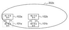
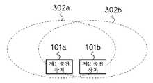
도 3은 2개의 송전 장치(101a, 101b) 및 2개의 수전 장치(102a, 102b)를 갖는 송수전 시스템의 구성예를 도시하는 도면이다. 송전 장치(101a 및 101b)는, 도 2의 송전 장치(101)와 동일한 구성을 갖는다. 수전 장치(102a 및 102b)는, 도 2의 수전 장치(102)와 동일한 구성을 갖는다.3 is a diagram showing a configuration example of a transmission and reception system having two
제1 송전 가능 범위(301a)는, 제1 송전 장치(101a)의 송전부(송전용 코일(202) 및 송전용 LC 공진기(203)를 포함)가 무선 송전 가능한 범위이다. 제1 송신 가능 범위(302a)는, 제1 송전 장치(101a)의 통신부(205)가 무선 송신 가능한 범위이며, 제1 송전 가능 범위(301a)보다 넓다.The first transmission
제2 송전 가능 범위(301b)는, 제2 송전 장치(101b)의 송전부(송전용 코일(202) 및 송전용 LC 공진기(203)를 포함)가 무선 송전 가능한 범위이다. 제2 송신 가능 범위(302b)는, 제2 송전 장치(101b)의 통신부(205)가 무선 송신 가능한 범위이며, 제2 송전 가능 범위(301b)보다 넓다.The second transmission
예를 들어, 송전 장치(101a 및 101b)의 송전부가 자계 공명 방식의 송전부인 경우에는, 송전 가능 범위(301a 및 301b)는 약 수십㎝이다. 또한, 송전 장치(101a 및 101b)의 통신부(205)가 Bluetooth(등록상표)의 통신 방식인 경우에는, 송신 가능 범위(302a 및 302b)는 약 수m이다.For example, when the power transmission parts of the
제1 송전 장치(101a)는, 제1 송전 가능 범위(301a) 내의 제1 수전 장치(102a)로 송전할 수 있고, 제1 송전 가능 범위(301a) 외의 제2 수전 장치(102b)로는 송전할 수 없다. 제2 송전 장치(101b)는, 제2 송전 가능 범위(301b) 내의 제2 수전 장치(102b)로 송전할 수 있고, 제2 송전 가능 범위(301b) 외의 제1 수전 장치(102a)로는 송전할 수 없다.The
또한, 제1 송전 장치(101a)는, 제1 송신 가능 범위(302a) 내의 제1 수전 장치(102a) 및 제2 수전 장치(102b)로 송신할 수 있고, 제1 송신 가능 범위(302a) 외의 수전 장치로는 송신할 수 없다. 제2 송전 장치(101b)는, 제2 송신 가능 범위(302b) 내의 제1 수전 장치(102a) 및 제2 수전 장치(102b)로 송신할 수 있고, 제2 송신 가능 범위(302b) 외의 수전 장치로는 송신할 수 없다.The
이상과 같이, 제1 송전 장치(101a)의 송전 대상은 제1 수전 장치(102a)뿐이며, 제2 송전 장치(101b)의 송전 대상은 제2 수전 장치(102b)뿐이다.As described above, only the first
이에 반해, 제1 송전 장치(101a)의 송신 대상은 제1 수전 장치(102a) 및 제2 수전 장치(102b)이며, 제2 송전 장치(101b)의 송신 대상은 제1 수전 장치(102a) 및 제2 수전 장치(102b)이다.On the other hand, the transmission targets of the
제1 송신 가능 범위(302a)는 제1 송전 가능 범위(301a)보다 넓고, 제2 송신 가능 범위(302b)는 제2 송전 가능 범위(301b)보다 넓다. 그로 인해, 송전 장치(101)의 송전 대상인 수전 장치(102)의 수와, 송전 장치(101)의 송신 대상인 수전 장치(102)의 수는 일치하지 않는다. 따라서, 송전 장치(101a 및 101b)는, 통신부(205)의 무선 통신에 의해서만, 송전 가능 범위(301a 및 301b) 내의 수전 장치의 수를 검출하는 것은 용이하지 않다. 이하, 송전 장치(101a 및 101b)가, 송전 가능 범위(301a 및 301b) 내의 수전 장치(102)의 수를 검출하고, 그 검출한 수전 장치(102)의 수에 따라서 적절한 전력의 송전을 행하는 방법을 설명한다.The first
도 4a 내지 도 4c는 제2 송전 장치(101b)의 송전 가능 범위 내에 존재하는 수전 장치의 수를 검출하는 방법을 설명하기 위한 도면이고, 도 5는 제2 송전 장치(101b)의 처리예를 나타내는 플로우차트이다. 도 4a 내지 도 4c에 있어서, 제1 송전 장치(101a)가 제1 수전 장치(102a)로 송전하고 있을 때, 제2 송전 장치(101b)가 제2 송전 가능 범위(301b) 내에 존재하는 수전 장치의 수를 검출하는 방법을 설명한다. 또한, 제1 수전 장치(102a) 및 제2 수전 장치(102b)는, 제2 송전 장치(101b)의 제2 송신 가능 범위(302b) 내에 존재한다.Figs. 4A to 4C are diagrams for explaining a method for detecting the number of power receiving devices existing within the power transmission allowable range of the
먼저, 스텝 S501에서는, 도 4a에 도시한 바와 같이, 제2 송전 장치(101b)의 송전부(송전용 코일(202) 및 송전용 LC 공진기(203)를 포함)는, 송전 제어 회로(204)의 제어에 의해, 정식 송전을 행하기 전에 제1 전력으로 테스트 송전을 개시한다.4A, the transmission unit (including the
이어서, 스텝 S502에서는, 제2 송전 장치(101b)는, 상기 테스트 송전 중에, 수전 중인 수전 장치를 검출한다. 구체적으로는, 제2 송전 장치(101b)의 통신부(205)는, 수전 중인 수전 장치를 검출하기 위해서 수전 장치 검출 통지를 송신한다. 제2 수전 장치(102b)는, 제2 송전 장치(101b)의 제2 송전 가능 범위(301b) 내에 존재하므로, 제2 송전 장치(101b)로부터 수전하고 있다. 제2 수전 장치(102b)의 통신부(215)는, 임계값 이상의 전력을 수전하고 있으므로, 상기 수전 장치 검출 통지를 제2 송전 장치(101b)로부터 수신하면, 수전하고 있다는 취지를 제2 송전 장치(101b)로 송신한다.Subsequently, in step S502, the
이에 반해, 제1 수전 장치(102a)는, 제2 송전 장치(101b)의 제2 송전 가능 범위(301b) 외에 위치하기 때문에, 제2 송전 장치(101b)로부터는 수전하지 않지만, 제1 송전 장치(101a)로부터 수전하고 있다. 그로 인해, 제1 수전 장치(102a)의 통신부(215)도, 임계값 이상의 전력을 수전하고 있으므로, 상기 수전 장치 검출 통지를 제2 송전 장치(101b)로부터 수신하면, 수전하고 있다는 취지를 제2 송전 장치(101b)로 송신한다.On the other hand, since the first
따라서, 제2 송전 장치(101b)는, 제1 수전 장치(102a) 및 제2 수전 장치(102b)로부터 수전하고 있다는 취지를 수신하고, 수전 중인 수전 장치가 2개의 수전 장치(102a 및 102b)인 것을 검출한다.Therefore, the
이어서, 스텝 S503에서는, 제2 송전 장치(101b)는, 수전 장치로부터 수전 중이라는 취지를 1개 이상 수신한 경우에는 스텝 S504로 진행하고, 수전 장치로부터 수전 중이라는 취지를 1개도 수신하지 않은 경우에는, 수전 중인 수전 장치가 존재하지 않으므로, 스텝 S511로 진행한다.Next, in step S503, if the
이어서, 스텝 S504에서는, 도 4b에 도시한 바와 같이, 제2 송전 장치(101b)의 송전부(송전용 코일(202) 및 송전용 LC 공진기(203)를 포함)는, 송전 제어 회로(204)의 제어에 의해, 상기 테스트 송전을 정지하고, 송전을 행하지 않는 상태로 한다.4B, the transmission unit (including the
이어서, 스텝 S505에서는, 제2 송전 장치(101b)는, 상기 테스트 송전 정지 후에, 수전 중인 수전 장치를 검출한다. 구체적으로는, 제2 송전 장치(101b)의 통신부(205)는, 수전 중인 수전 장치를 검출하기 위해서 수전 장치 검출 통지를 송신한다. 제2 수전 장치(102b)는, 수전하지 않는 상태가 되어, 임계값 이상의 전력을 수전하고 있지 않으므로, 상기 수전 장치 검출 통지가 송신되더라도, 수전하고 있다는 취지를 송신하지 않는다.Subsequently, in step S505, the
이에 반해, 제1 수전 장치(102a)는, 제1 송전 장치(101a)로부터 수전하여, 임계값 이상의 전력을 수전하고 있으므로, 상기 수전 장치 검출 통지를 수신하면, 수전하고 있다는 취지를 제2 송전 장치(101b)로 송신한다.On the other hand, the first
따라서, 제2 송전 장치(101b)는, 제1 수전 장치(102a)로부터만 수전하고 있다는 취지를 수신하고, 수전 중인 수전 장치가 1개의 수전 장치(102a)인 것을 검출한다.Therefore, the
이어서, 스텝 S506에서는, 제2 송전 장치(101b)는, 스텝 S502에서 검출한 수전 장치의 수와 스텝 S505에서 검출한 수전 장치의 수가 같은지 여부를 체크한다. 같지 않은 경우에는 스텝 S507로 진행하고, 동일한 경우에는, 제2 송전 장치(101b)의 제2 송전 가능 범위(301b) 내에 수전 장치가 존재하지 않는 것을 의미하므로, 스텝 S511로 진행한다.Subsequently, in step S506, the
이어서, 스텝 S507에서는, 도 4c에 도시한 바와 같이, 제2 송전 장치(101b)는, 스텝 S502에서 응답이 있었던 수전 장치의 수에서, 스텝 S505에서 응답이 있었던 수전 장치의 수를 감산함으로써, 무응답으로 변화한 수전 장치의 수를 검출한다. 즉, 제2 송전 장치(101b)의 송전 제어 회로(204)는, 스텝 S502에서 검출된 수전 장치(102a 및 102b)의 수인 2개에서, 스텝 S505에서 검출된 수전 장치(102a)의 수인 1개를 감산함으로써, 자신의 제2 송전 가능 범위(301b) 내에 존재하는 수전 장치의 수가 제2 수전 장치(102b) 1개인 것을 검출할 수 있다.Subsequently, in step S507, the
이어서, 스텝 S508 및 S509에서는, 제2 송전 장치(101b)의 송전부(송전용 코일(202) 및 송전용 LC 공진기(203)를 포함)는, 송전 제어 회로(204)가 고주파 전원 회로(201) 내의 증폭기의 게인을 제어함으로써, 스텝 S507에서 검출된 수전 장치(102b)의 수인 1개에 적합한 전력으로 송전을 행한다. 이에 의해, 제2 송전 장치(101b)로부터 제2 수전 장치(102b)로 적절한 전력이 송전되어, 제2 수전 장치(102b)의 과잉 수전을 방지하고, 이상 발열을 방지할 수 있다.Next, in steps S508 and S509, the transmission unit (including the
이어서, 스텝 S510에서는, 제2 수전 장치(102b)의 통신부(215)는, 충전을 완료하면, 수전 완료 통지를 제2 송전 장치(101b)로 송신한다. 제2 송전 장치(101b)의 통신부(205)는, 제2 수전 장치(102b)로부터 수전 완료 통지를 수신하면, 스텝 S511로 진행한다.Then, in step S510, the
스텝 S511에서는, 제2 송전 장치(101b)의 송전부(송전용 코일(202) 및 송전용 LC 공진기(203)를 포함)는, 송전 제어 회로(204)의 제어에 의해, 송전을 정지한다.In step S511, the transmission unit (including the
상기에서는 제2 송전 장치(101b)의 처리를 예로 들어 설명했지만, 그 외의 송전 장치(101a)를 포함하는 모든 송전 장치(101)의 처리는, 제2 송전 장치(101b)의 처리와 마찬가지이다.Although the processing of the
이상과 같이, 먼저, 스텝 S502에서, 송전 장치(101)의 송전 제어 회로(204)는, 송전부가 제1 전력으로 송전했을 때 임계값 이상의 전력의 수전을 하고 있는 수전 장치(102)로부터 수전하고 있다는 취지의 응답을 통신부(205)가 수신한 수전 장치(102)의 수를 검출한다. 그 후, 스텝 S505에서, 송전 장치(101)의 송전 제어 회로(204)는, 송전부가 송전하지 않을 때 임계값 이상의 전력의 수전을 하고 있는 수전 장치(102)로부터 수전하고 있다는 취지의 응답을 통신부(205)가 수신한 수전 장치(102)의 수를 검출한다. 그 후, 스텝 S507에서는, 송전 장치(101)의 송전 제어 회로(204)는, 스텝 S502에서 검출한 수전 장치(102)의 수와 스텝 S505에서 검출한 수전 장치의 수에 따라서, 송전부의 송전 가능 범위 내에 존재하는 수전 장치(102)의 수를 검출한다. 그 후, 스텝 S508에서는, 송전 장치(101)의 송전 제어 회로(204)는, 스텝 S507에서 검출된 수전 장치(102)의 수에 따라서, 송전부의 무선 송전의 전력을 제어한다.As described above, first, in step S502, the power
또한, 스텝 S501 및 S502의 처리와, 스텝 S504 및 S505의 처리의 순서를 반대로 해도 된다. 즉, 먼저 스텝 S504의 처리를 행하고, 다음에 스텝 S505의 처리를 행하고, 다음에 스텝 S501의 처리를 행하고, 다음에 스텝 S502의 처리를 행하고, 그 후, 스텝 S507 이후의 처리를 행하도록 해도 된다.The processing of steps S501 and S502 and the processing of steps S504 and S505 may be reversed. That is, the process of step S504 may be performed first, the process of step S505 may be performed first, the process of step S501 may be performed first, the process of step S502 may be performed first, and the process after step S507 may be performed thereafter .
즉, 먼저, 스텝 S505와 같이, 송전 장치(101)의 송전 제어 회로(204)는, 송전부가 송전하지 않을 때 임계값 이상의 전력의 수전을 하고 있는 수전 장치(102)로부터 수전하고 있다는 취지의 응답을 통신부(205)가 수신한 수전 장치(102)의 수를 검출한다. 그 후, 스텝 S502와 같이, 송전 장치(101)의 송전 제어 회로(204)는, 송전부가 제1 전력으로 송전했을 때 임계값 이상의 전력의 수전을 하고 있는 수전 장치(102)로부터 수전하고 있다는 취지의 응답을 통신부(205)가 수신한 수전 장치(102)의 수를 검출한다. 그 후, 스텝 S507에서는, 송전 장치(101)의 송전 제어 회로(204)는, 스텝 S502에서 검출한 수전 장치(102)의 수와 스텝 S505에서 검출한 수전 장치의 수에 따라서, 송전부의 송전 가능 범위 내에 존재하는 수전 장치(102)의 수를 검출한다. 그 후, 스텝 S508에서는, 송전 장치(101)의 송전 제어 회로(204)는, 스텝 S507에서 검출된 수전 장치(102)의 수에 따라서, 송전부의 무선 송전의 전력을 제어한다.That is, first, as in step S505, the
또한, 스텝 S504에서는, 송전을 정지하는 예를 나타냈지만, 스텝 S501의 테스트 송전의 제1 전력보다 작은 제2 전력(극소 전력을 포함)으로 송전하도록 해도 된다.In the step S504, the transmission is stopped. However, the transmission may be performed with the second power (including the minimum power) smaller than the first power of the test transmission in step S501.
즉, 스텝 S502에서는, 송전 장치(101)의 송전 제어 회로(204)는, 송전부가 제1 전력으로 송전했을 때 임계값 이상의 전력의 수전을 하고 있는 수전 장치(102)로부터 수전하고 있다는 취지의 응답을 통신부(205)가 수신한 수전 장치의 수를 검출한다. 또한, 스텝 S504 및 S505와 마찬가지로, 송전 장치(101)의 송전 제어 회로(204)는, 송전부가 제1 전력보다 작은 제2 전력으로 송전했을 때 임계값 이상의 전력의 수전을 하고 있는 수전 장치(102)로부터 수전하고 있다는 취지의 응답을 통신부(205)가 수신한 수전 장치(102)의 수를 검출한다. 그 후, 스텝 S508에서는, 송전 장치(101)의 송전 제어 회로(204)는, 스텝 S507에서 검출한 수전 장치의 수에 따라서, 송전부의 무선 송전의 전력을 제어한다. 이 경우도, 상기한 바와 같이 스텝 S502와 S505의 처리의 순서는, 반대여도 상관없다.That is, in step S502, the
이상과 같이, 수전 장치(102)가 노트북형 퍼스널 컴퓨터 또는 휴대 단말기 등인 경우에는, 수전 장치(102)가 이동 가능하다. 본 실시 형태에 따르면, 송전 장치(101)의 송전 가능 범위 내의 수전 장치(102)의 수가 바뀌는 경우에도, 자신의 송전 가능 범위 내의 수전 장치(102)의 수를 검출하고, 그 수에 따라서 적절한 전력으로 무선 송전할 수 있다.As described above, when the
(제2 실시 형태)(Second Embodiment)
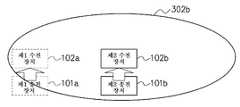
도 6은, 제2 실시 형태에 따른 송수전 시스템의 구성예를 도시하는 도면이다. 송수전 시스템은, 2개의 송전 장치(101a, 101b) 및 4개의 수전 장치(102a, 102b, 102c, 102d)를 갖는다. 제1 송전 가능 범위(301a)는, 제1 송전 장치(101a)의 송전부가 송전 가능한 범위이며, 제1 수전 장치(102a) 및 제2 수전 장치(102b)가 존재한다. 제2 송전 가능 범위(301b)는, 제2 송전 장치(101b)의 송전부가 송전 가능한 범위이며, 제3 수전 장치(102c) 및 제4 수전 장치(102d)가 존재한다.Fig. 6 is a diagram showing a configuration example of a water supply and reception system according to the second embodiment. Fig. The transmission / reception system has two
제1 송신 가능 범위(302a)는, 제1 송전 장치(101a)의 통신부(205)가 송신 가능한 범위이며, 제1 송전 가능 범위(301a)보다 넓고, 제1 수전 장치(102a), 제2 수전 장치(102b), 제3 수전 장치(102c) 및 제4 수전 장치(102d)가 존재한다. 제2 송신 가능 범위(302b)는, 제2 송전 장치(101b)의 통신부(205)가 송신 가능한 범위이며, 제2 송전 가능 범위(301b)보다 넓고, 제1 수전 장치(102a), 제2 수전 장치(102b), 제3 수전 장치(102c) 및 제4 수전 장치(102d)가 존재한다.The first
도 7 내지 도 10은, 도 6의 송수전 시스템의 처리예를 나타내는 시퀀스 플로우도이다. 먼저, 도 7에 있어서, 스텝 701에서는, 제1 송전 장치(101a)는, 충전 처리의 개시를 지시한다.Figs. 7 to 10 are sequence flow charts showing an example of processing of the transmission / reception system of Fig. 6; Fig. First, in Fig. 7, in step 701, the
이어서, 스텝 702에서는, 도 5의 스텝 S501에 대응하여, 제1 송전 장치(101a)의 송전부는, 제1 전력으로 테스트 송전을 개시한다. 제1 수전 장치(102a) 및 제2 수전 장치(102b)는, 제1 송전 장치(101a)의 제1 송전 가능 범위(301a) 내에 위치하므로, 스텝 703 및 704에서, 제1 송전 장치(101a)로부터의 수전을 개시하고, 그 수전에 의해 전원이 투입된다.Subsequently, in step 702, corresponding to step S501 in Fig. 5, the transmission unit of the
이에 반해, 제3 수전 장치(102c) 및 제4 수전 장치(102d)는, 제1 송전 장치(101a)의 제1 송전 가능 범위(301a) 외에 위치하므로, 수전을 하지 않으며, 전원이 투입되지 않는다.On the other hand, since the third and fourth
이어서, 스텝 705에서는, 도 5의 스텝 S502에 대응하여, 제1 송전 장치(101a)의 통신부(205)는, 수전 중인 수전 장치를 검출하기 위해서 수전 장치 검출 통지를 송신한다.Subsequently, at step 705, corresponding to step S502 of Fig. 5, the
그러면, 스텝 706에서는, 제1 수전 장치(102a)는, 수전 중이므로, 상기 수전 장치 검출 통지를 제1 송전 장치(101a)로부터 수신하면, 수전 중이라는 취지를 제1 송전 장치(101a)에 응답 송신한다. 스텝 707에서는, 제2 수전 장치(102b)도, 수전 중이므로, 상기 수전 장치 검출 통지를 제1 송전 장치(101a)로부터 수신하면, 수전 중이라는 취지를 제1 송전 장치(101a)에 응답 송신한다.Then, in step 706, since the first
이에 반해, 스텝 708에서는, 제3 수전 장치(102c)는, 수전 중이 아니므로, 상기 수전 장치 검출 통지가 송신되더라도, 응답하지 않는다. 스텝 709에서는, 제4 수전 장치(102d)도, 수전 중이 아니므로, 상기 수전 장치 검출 통지가 송신되더라도, 응답하지 않는다.On the other hand, in step 708, since the third
이어서, 스텝 710에서는, 제1 송전 장치(101a)의 송전 제어 회로(204)는, 스텝 706 및 707에서 응답이 있었던 제1 수전 장치(102a) 및 제2 수전 장치(102b)의 정보를 기억부(711)에 기억한다.Subsequently, in step 710, the
이어서, 스텝 712에서는, 도 5의 스텝 S504에 대응하여, 제1 송전 장치(101a)의 송전부는, 테스트 송전을 정지한다. 그러면, 스텝 713에서는, 제1 수전 장치(102a)는, 수전을 정지하고, 전원이 절단된다. 스텝 714에서는, 제2 수전 장치(102b)도, 수전을 정지하고, 전원이 절단된다.Subsequently, in step 712, corresponding to step S504 in Fig. 5, the power transmission unit of the
이어서, 스텝 715에서는, 도 5의 스텝 S505에 대응하여, 제1 송전 장치(101a)의 통신부(205)는, 수전 중인 수전 장치를 검출하기 위해서 수전 장치 검출 통지를 송신한다.Next, in step 715, the
그러면, 도 8에 도시한 바와 같이, 스텝 801에서는, 제1 수전 장치(102a)는, 수전 중이 아니므로, 상기 수전 장치 검출 통지가 송신되더라도, 응답하지 않는다. 스텝 802에서는, 제2 수전 장치(102b)도, 수전 중이 아니므로, 상기 수전 장치 검출 통지가 송신되더라도, 응답하지 않는다. 스텝 803에서는, 제3 수전 장치(102c)도, 수전 중이 아니므로, 상기 수전 장치 검출 통지가 송신되더라도, 응답하지 않는다. 스텝 804에서는, 제4 수전 장치(102d)도, 수전 중이 아니므로, 상기 수전 장치 검출 통지가 송신되더라도, 응답하지 않는다.Then, as shown in Fig. 8, in step 801, since the first
이어서, 스텝 805에서는, 제1 송전 장치(101a)의 송전 제어 회로(204)는, 응답이 있었던 수전 장치의 정보를 기억부(711)로부터 삭제하는 처리를 행한다. 그러나, 스텝 805에서는, 응답이 있었던 수전 장치가 존재하지 않으므로, 제1 송전 장치(101a)의 송전 제어 회로(204)는, 기억부(711)의 정보의 삭제를 행하지 않는다.Subsequently, at step 805, the
이어서, 스텝 806에서는, 도 5의 스텝 S507에 대응하여, 제1 송전 장치(101a)의 송전 제어 회로(204)는, 기억부(711)에 기억되어 있는 제1 수전 장치(102a) 및 제2 수전 장치(102b)의 2개의 수전 장치가 자신의 제1 송전 가능 범위(301a) 내에 존재하는 것을 검출한다.5, the
이어서, 스텝 807에서는, 도 5의 스텝 S508에 대응하여, 제1 송전 장치(101a)의 송전 제어 회로(204)는, 스텝 806에서 검출된 수전 장치의 수에 적합한 전력이 되도록, 고주파 전원 회로(201) 내의 증폭기의 게인을 설정한다.Next, in step 807, the
이어서, 스텝 808에서는, 도 5의 스텝 S509에 대응하여, 제1 송전 장치(101a)의 송전부는, 상기 설정된 적절한 전력으로의 송전을 개시한다. 그러면, 스텝 809에서는, 제1 수전 장치(102a)는, 적절한 전력으로 수전하고, 전원이 투입된다. 스텝 810에서는, 제2 수전 장치(102b)도, 적절한 전력으로 수전하고, 전원이 투입된다.Subsequently, in
이에 반해, 제3 수전 장치(102c) 및 제4 수전 장치(102d)는, 제1 송전 장치(101a)의 제1 송전 가능 범위(301a) 외에 위치하므로, 수전하지 않는다.On the other hand, the third and fourth
이어서, 도 9에 도시한 바와 같이, 스텝 901에서는, 제2 송전 장치(101b)는, 충전 처리의 개시를 지시한다.Next, as shown in Fig. 9, in
이어서, 스텝 902에서는, 도 5의 스텝 S501에 대응하여, 제2 송전 장치(101b)의 송전부는, 제1 전력으로 테스트 송전을 개시한다. 제3 수전 장치(102c) 및 제4 수전 장치(102d)는, 제2 송전 장치(101b)의 제2 송전 가능 범위(301b) 내에 위치하므로, 스텝 903 및 904에서, 제2 송전 장치(101b)로부터의 수전을 개시하고, 그 수전에 의해 전원이 투입된다.Subsequently, in
이어서, 스텝 905에서는, 도 5의 스텝 S502에 대응하여, 제2 송전 장치(101b)의 통신부(205)는, 수전 중인 수전 장치를 검출하기 위해서 수전 장치 검출 통지를 송신한다.Next, in
그러면, 스텝 906에서는, 제1 수전 장치(102a)는, 제1 송전 장치(101a)로부터 수전 중이므로, 상기 수전 장치 검출 통지를 제2 송전 장치(101b)로부터 수신하면, 수전 중이라는 취지를 제2 송전 장치(101b)에 응답 송신한다. 스텝 907에서는, 제2 수전 장치(102b)도, 제1 송전 장치(101a)로부터 수전 중이므로, 상기 수전 장치 검출 통지를 제2 송전 장치(101b)로부터 수신하면, 수전 중이라는 취지를 제2 송전 장치(101b)에 응답 송신한다.Then, in
이에 반해, 스텝 908에서는, 제3 수전 장치(102c)는, 제2 송전 장치(101b)로부터 수전 중이므로, 상기 수전 장치 검출 통지를 제2 송전 장치(101b)로부터 수신하면, 수전 중이라는 취지를 제2 송전 장치(101b)에 응답 송신한다. 스텝 909에서는, 제4 수전 장치(102d)도, 제2 송전 장치(101b)로부터 수전 중이므로, 상기 수전 장치 검출 통지를 제2 송전 장치(101b)로부터 수신하면, 수전 중이라는 취지를 제2 송전 장치(101b)에 응답 송신한다.On the other hand, in
이어서, 스텝 910에서는, 제2 송전 장치(101b)의 송전 제어 회로(204)는, 스텝 906 내지 909에서 응답이 있었던 제1 수전 장치(102a) 내지 제4 수전 장치(102d)의 정보를 기억부(911)에 기억한다.Subsequently, in
이어서, 스텝 912에서는, 도 5의 스텝 S504에 대응하여, 제2 송전 장치(101b)의 송전부는, 테스트 송전을 정지한다. 그러면, 스텝 913에서는, 제3 수전 장치(102c)는, 수전을 정지하고, 전원이 절단된다. 스텝 914에서는, 제4 수전 장치(102d)도, 수전을 정지하고, 전원이 절단된다.Subsequently, in
이어서, 스텝 915에서는, 도 5의 스텝 S505에 대응하여, 제2 송전 장치(101b)의 통신부(205)는, 수전 중인 수전 장치를 검출하기 위해서 수전 장치 검출 통지를 송신한다.Next, in
그러면, 도 10에 도시한 바와 같이, 스텝 1001에서는, 제1 수전 장치(102a)는, 제1 송전 장치(101a)로부터 수전 중이므로, 상기 수전 장치 검출 통지를 제2 송전 장치(101b)로부터 수신하면, 수전 중이라는 취지를 제2 송전 장치(101b)에 응답 송신한다. 스텝 1002에서는, 제2 수전 장치(102b)도, 제1 송전 장치(101a)로부터 수전 중이므로, 상기 수전 장치 검출 통지를 제2 송전 장치(101b)로부터 수신하면, 수전 중이라는 취지를 제2 송전 장치(101b)에 응답 송신한다.Then, as shown in Fig. 10, in step 1001, since the first
이에 반해, 스텝 1003에서는, 제3 수전 장치(102c)는, 수전 중이 아니므로, 상기 수전 장치 검출 통지가 송신되더라도, 응답하지 않는다. 스텝 1004에서는, 제4 수전 장치(102d)도, 수전 중이 아니므로, 상기 수전 장치 검출 통지가 송신되더라도, 응답하지 않는다.On the other hand, in step 1003, since the third
이어서, 스텝 1005에서는, 제2 송전 장치(101b)의 송전 제어 회로(204)는, 스텝 1001 및 1002에서 응답이 있었던 제1 수전 장치(102a) 및 제2 수전 장치(102b)의 정보를 기억부(911)로부터 삭제한다. 이에 의해, 기억부(911)에는, 제3 수전 장치(102c) 및 제4 수전 장치(102d)의 정보가 남는다.Subsequently, at
이어서, 스텝 1006에서는, 도 5의 스텝 S507에 대응하여, 제2 송전 장치(101b)의 송전 제어 회로(204)는, 기억부(911)에 기억되어 있는 제3 수전 장치(102c) 및 제4 수전 장치(102d)의 2개의 수전 장치가 자신의 제2 송전 가능 범위(301b) 내에 존재하는 것을 검출한다.5, the
이어서, 스텝 1007에서는, 도 5의 스텝 S508에 대응하여, 제2 송전 장치(101b)의 송전 제어 회로(204)는, 스텝 1006에서 검출된 수전 장치의 수에 적합한 전력이 되도록, 고주파 전원 회로(201) 내의 증폭기의 게인을 설정한다.5, the
이어서, 스텝 1008에서는, 도 5의 스텝 S509에 대응하여, 제2 송전 장치(101b)의 송전부는, 상기 설정된 적절한 전력으로의 송전을 개시한다. 그러면, 스텝 1009에서는, 제3 수전 장치(102c)는, 적절한 전력으로 수전하고, 전원이 투입된다. 스텝 1010에서는, 제4 수전 장치(102d)도, 적절한 전력으로 수전하고, 전원이 투입된다.Subsequently, in step 1008, corresponding to step S509 in Fig. 5, the transmission unit of the
이상과 같이, 본 실시 형태에 따르면, 제1 송전 장치(101a)는, 제1 송전 가능 범위(301a) 내의 2개의 수전 장치(102a 및 102b)에 적합한 전력으로 송전할 수 있다. 제2 송전 장치(101b)는, 제2 송전 가능 범위(301b) 내의 2개의 수전 장치(102c 및 102d)에 적합한 전력으로 송전할 수 있다.As described above, according to the present embodiment, the
(제3 실시 형태)(Third Embodiment)
도 11은, 제3 실시 형태에 따른 제1 송전 장치(101a)의 송전예를 나타내는 타임차트이다. 이하, 본 실시 형태가 제1 및 제2 실시 형태와 다른 점을 설명한다. 제1 송전 장치(101a)는, 도 5의 스텝 S501 내지 S509의 처리를 일정한 주기로 정기적으로 행한다. 이에 의해, 도 11에 도시한 바와 같이, 제1 송전 장치(101a)는, 스텝 S504의 송전 정지가 정기적으로 행해진다.11 is a time chart showing a transmission example of the
즉, 제1 송전 장치(101a)의 송전 제어 회로(204)는, 스텝 S501에서 송전부가 제1 전력으로 송전했을 때 스텝 S502에서 통신부(205)가 수신한 수전 장치(102)의 수와, 스텝 S504에서 송전부가 송전하지 않을 때 스텝 S505에서 통신부(205)가 수신한 수전 장치(102)의 수에 따라서, 스텝 S508에서 송전부의 무선 송전의 전력을 제어하는 처리를 정기적으로 행한다.That is, the power
수전 장치(102)는, 충전 중에 이동시킬 수 있거나, 증가시킬 수 있는 것이 상정된다. 본 실시 형태에서는, 제1 송전 장치(101a)는, 제1 송전 가능 범위(301a) 내에 존재하는 수전 장치(102)의 수를 정기적으로 검출해서 송전 전력을 제어하므로, 제1 송전 가능 범위(301a) 내의 수전 장치(102)의 수가 변화하더라도, 적절한 전력으로 송전을 행할 수 있다.It is assumed that the
또한, 우발적으로 가까이에 있는 제1 송전 장치(101a) 및 제2 송전 장치(101b)가 동시에 충전 처리를 개시해 버린 경우, 제1 송전 장치(101a) 및 제2 송전 장치(101b)가 같은 주기로 정기적으로 상기 전력 제어 처리를 행하면, 제1 송전 장치(101a)는, 제1 송전 가능 범위(301a) 내에 제1 수전 장치(102a) 내지 제4 수전 장치(102d)가 존재한다고 잘못 검출하고, 제2 송전 장치(101b)도, 제2 송전 가능 범위(301b) 내에 제1 수전 장치(102a) 내지 제4 수전 장치(102d)가 존재한다고 잘못 검출해 버린다. 따라서, 그와 같은 우발적인 경우에도 대응 가능한 실시 형태를 후술하는 제4 실시 형태에서 설명한다.When the
(제4 실시 형태)(Fourth Embodiment)
도 12는 제4 실시 형태에 따른 제1 송전 장치(101a) 및 제2 송전 장치(101b)의 송전예를 나타내는 타임차트이다. 이하, 본 실시 형태가 제3 실시 형태와 다른 점을 설명한다. 제2 송전 장치(101b)는 제3 실시 형태의 제1 송전 장치(101a)와 마찬가지로, 도 5의 스텝 S501 내지 S509의 처리를 일정한 주기로 정기적으로 행한다. 이에 의해, 도 12에 도시한 바와 같이, 제2 송전 장치(101b)는, 스텝 S504의 송전 정지가 일정한 주기로 정기적으로 행해진다.12 is a time chart showing a transmission example of the
이에 반해, 제1 송전 장치(101a)는, 도 5의 스텝 S501 내지 S509의 처리를 랜덤의 주기로 복수회 행한다. 이에 의해, 도 12에 도시한 바와 같이, 제1 송전 장치(101a)는 스텝 S504의 송전 정지가 랜덤의 주기로 복수회 행해진다.On the other hand, the
즉, 제1 송전 장치(101a)의 송전 제어 회로(204)는, 스텝 S501에서 송전부가 제1 전력으로 송전했을 때 스텝 S502에서 통신부(205)가 수신한 수전 장치(102)의 수와, 스텝 S504에서 송전부가 송전하지 않을 때 스텝 S505에서 통신부(205)가 수신한 수전 장치(102)의 수에 따라서, 스텝 S508에서 송전부의 무선 송전의 전력을 제어하는 처리를 랜덤의 주기로 복수회 행한다.That is, the power
본 실시 형태에 따르면, 우발적으로 가까이에 있는 제1 송전 장치(101a) 및 제2 송전 장치(101b)가 동시에 충전 처리를 개시해 버린 경우에도, 제1 송전 장치(101a) 및 제2 송전 장치(101b)는, 2회째 이후의 전력 제어 처리를 다른 타이밍으로 행하므로, 올바른 전력 제어를 행할 수 있다. 즉, 제1 송전 장치(101a)는, 제1 송전 가능 범위(301a) 내에 제1 수전 장치(102a) 및 제2 수전 장치(102b)가 존재하면 올바른 검출을 행하고, 제2 송전 장치(101b)도, 제2 송전 가능 범위(301b) 내에 제3 수전 장치(102c) 및 제4 수전 장치(102d)가 존재하면 올바른 검출을 행하여, 적절한 전력으로 송신할 수 있다.According to the present embodiment, even when the
(제5 실시 형태)(Fifth Embodiment)
도 13a, 도 13b, 도 14a 및 도 14b는, 제5 실시 형태에 따른 제1 송전 장치(101a) 및 제2 송전 장치(101b)의 처리예를 도시하는 도면이다.Figs. 13A, 13B, 14A, and 14B are diagrams showing processing examples of the
도 13a에서는, 제1 송전 장치(101a)는, 제2 송전 장치(101b)의 제2 송신 가능 범위(302b) 외에 위치하고, 제2 송전 장치(101b)는, 제1 송전 장치(101a)의 제1 송신 가능 범위(302a) 외에 위치한다.13A, the
제1 송전 장치(101a)의 통신부(205)가 송전 장치 검출 통지를 송신하면, 제1 송신 가능 범위(302a) 내에 제2 송전 장치(101b)가 존재하지 않으므로, 제2 송전 장치(101b)의 통신부(205)는, 제1 송전 장치(101a)로부터 송전 장치 검출 통지를 수신할 수 없으며, 그 응답을 행하지 않는다. 제1 송전 장치(101a)의 송전 제어 회로(204)는, 통신부(205)가 상기 응답을 수신하지 않으므로, 제1 송신 가능 범위(302a) 내에 제2 송전 장치(101b)가 존재하지 않는 것을 검출할 수 있다.When the
마찬가지로, 제2 송전 장치(101b)의 통신부(205)가 송전 장치 검출 통지를 송신하면, 제2 송신 가능 범위(302b) 내에 제1 송전 장치(101a)가 존재하지 않으므로, 제1 송전 장치(101a)의 통신부(205)는, 제2 송전 장치(101b)로부터 송전 장치 검출 통지를 수신할 수 없으며, 그 응답을 행하지 않는다. 제2 송전 장치(101b)의 송전 제어 회로(204)는, 통신부(205)가 상기 응답을 수신하지 않으므로, 제2 송신 가능 범위(302b) 내에 제1 송전 장치(101a)가 존재하지 않는 것을 검출할 수 있다.Likewise, when the
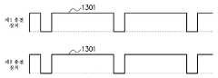
도 13b는, 도 13a의 상태에 있어서의 제1 송전 장치(101a) 및 제2 송전 장치(101b)의 송전예를 나타내는 타임차트이다. 도 13a의 경우, 제1 송전 장치(101a)는, 제2 송신 가능 범위(302b) 내에 존재하지 않으므로, 당연히 제2 송전 가능 범위(301b) 내에도 존재하지 않는다. 마찬가지로, 제2 송전 장치(101b)는, 제1 송신 가능 범위(302a) 내에 존재하지 않으므로, 당연히 제1 송전 가능 범위(301a) 내에도 존재하지 않는다.13B is a time chart showing a transmission example of the
이 경우, 제1 송전 장치(101a) 및 제2 송전 장치(101b)는, 도 11과 마찬가지로, 전력 제어 처리를 정기적으로 행하기 때문에, 정기적인 송전(1301)이 행해진다. 제1 송전 장치(101a) 및 제2 송전 장치(101b)는, 서로 위치가 이격되어 있으므로, 동일한 타이밍으로 전력 제어 처리를 행해도, 올바른 전력 제어 처리를 행할 수 있다.In this case, the
도 14a에서는, 제1 송전 장치(101a)는, 제2 송전 장치(101b)의 제2 송신 가능 범위(302b) 내에 위치하고, 제2 송전 장치(101b)는, 제1 송전 장치(101a)의 제1 송신 가능 범위(302a) 내에 위치한다.14A, the
제1 송전 장치(101a)의 통신부(205)가 송전 장치 검출 통지를 송신하면, 제1 송신 가능 범위(302a) 내에 제2 송전 장치(101b)가 존재하므로, 제2 송전 장치(101b)의 통신부(205)는, 제1 송전 장치(101a)로부터 송전 장치 검출 통지를 수신하고, 그 응답을 송신한다. 제1 송전 장치(101a)의 송전 제어 회로(204)는, 통신부(205)가 상기 응답을 수신하므로, 제1 송신 가능 범위(302a) 내에 제2 송전 장치(101b)가 존재하는 것을 검출할 수 있다.When the
마찬가지로, 제2 송전 장치(101b)의 통신부(205)가 송전 장치 검출 통지를 송신하면, 제2 송신 가능 범위(302b) 내에 제1 송전 장치(101a)가 존재하므로, 제1 송전 장치(101a)의 통신부(205)는, 제2 송전 장치(101b)로부터 송전 장치 검출 통지를 수신하고, 그 응답을 송신한다. 제2 송전 장치(101b)의 송전 제어 회로(204)는, 통신부(205)가 상기 응답을 수신하므로, 제2 송신 가능 범위(302b) 내에 제1 송전 장치(101a)가 존재하는 것을 검출할 수 있다.Similarly, when the
도 14b는, 도 14a의 상태에 있어서의 제1 송전 장치(101a) 및 제2 송전 장치(101b)의 송전예를 나타내는 타임차트이다. 도 14a의 경우, 제1 송전 장치(101a)는, 제2 송신 가능 범위(302b) 내에 존재하므로, 제2 송전 가능 범위(301b) 내에도 존재할 가능성이 있다. 마찬가지로, 제2 송전 장치(101b)는, 제1 송신 가능 범위(302a) 내에 존재하므로, 제1 송전 가능 범위(301a) 내에도 존재할 가능성이 있다.Fig. 14B is a time chart showing an example of transmission of the
이 경우, 제1 송전 장치(101a)는, 도 11과 마찬가지로, 제1 주기로 전력 제어 처리를 정기적으로 행하기 때문에, 제1 주기가 정기적인 송전(1301)이 행해진다. 제2 송전 장치(101b)는, 도 11과 마찬가지로, 상기 제1 주기와는 다른 제2 주기로 전력 제어 처리를 정기적으로 행하기 때문에, 제2 주기가 정기적인 송전(1302)이 행해진다.In this case, as in the case of Fig. 11, the
즉, 송전 장치(101)의 송전 제어 회로(204)는, 통신부(205)의 송신 가능 범위 내에 다른 송전 장치(101)가 존재한다는 취지를 통신부(205)가 수신했을 때는 정기적으로 행하는 전력 제어 처리의 주기를, 상기 다른 송전 장치(101)가 정기적으로 행하는 전력 제어 처리의 주기와 다르게 한다.That is, the power
제1 송전 장치(101a) 및 제2 송전 장치(101b)는, 서로 위치가 가까우므로, 정기적 행하는 주기를 다르게 함으로써, 적어도 2회째 이후의 전력 제어 처리의 타이밍을 어긋나게 해서, 올바른 전력 제어 처리를 행할 수 있다.Since the positions of the
제1 내지 제5 실시 형태에 따르면, 송전 장치(101)는, 송전 가능 범위 내에 존재하는 수전 장치(102)의 수를 검출하고, 그 수에 따라서 적절한 전력으로 무선 송전할 수 있다. 이에 의해, 송전 장치(101)가 과도한 전력을 송전하고, 수전 장치(102)에 이상 과열이 발생해 버리는 것 같은 문제를 방지할 수 있으며, 쓸데없는 송전 손실을 방지할 수 있다.According to the first to fifth embodiments, the
또한, 상기 실시 형태는, 모두 본 발명을 실시함에 있어서 구체화의 예를 나타낸 것에 지나지 않으며, 이들에 의해 본 발명의 기술적 범위가 한정적으로 해석되어서는 안되는 것이다. 즉, 본 발명은 그 기술 사상, 또는 그 주요한 특징으로부터 일탈하지 않고, 다양한 형태로 실시할 수 있다.The foregoing embodiments are merely examples of embodiments in the practice of the present invention, and the technical scope of the present invention should not be construed as being limited thereto. That is, the present invention can be carried out in various forms without departing from the technical idea or the main features thereof.
송전 가능 범위 내의 수전 장치의 수를 검출하고, 그 수에 따라서 적절한 전력으로 무선 송전할 수 있다.
It is possible to detect the number of the water receiving devices within the transmission allowable range, and to perform wireless transmission with appropriate power according to the number.
Claims (10)
Translated fromKorean상기 송전부의 송전 가능 범위보다 넓은 범위 내에서 무선 통신을 행하는 통신부와,
상기 송전부의 무선 송전의 전력을 제어하는 송전 제어 회로를 갖고,
상기 송전 제어 회로는, 상기 송전부가 제1 전력으로 송전했을 때에 임계값 이상의 전력의 수전을 하고 있는 수전 장치로부터 수전하고 있다는 취지의 응답을 상기 통신부가 수신한 수전 장치의 수와, 상기 송전부가 송전하지 않을 때 또는 상기 제1 전력보다 작은 제2 전력으로 송전했을 때에 상기 임계값 이상의 전력의 수전을 하고 있는 수전 장치로부터 수전하고 있다는 취지의 응답을 상기 통신부가 수신한 수전 장치의 수에 따라서, 상기 송전부의 무선 송전의 전력을 제어하는 것을 특징으로 하는 송전 장치.A transmission unit for performing wireless transmission,
A communication unit that performs wireless communication within a range wider than a transmission allowable range of the transmission unit;
And a transmission control circuit for controlling power of radio transmission of the transmission unit,
Wherein the transmission control circuit controls the number of the power reception devices received by the communication section and the number of power transmission devices received by the power transmission device when the power transmission section receives the first power, When receiving the power from the power receiving apparatus that receives power of the power equal to or higher than the threshold value when the power is transmitted with the second power smaller than the first power, And controls power of wireless transmission of the transmission unit.
상기 송전 제어 회로는, 상기 송전부가 상기 제1 전력으로 송전했을 때에 상기 임계값 이상의 전력의 수전을 하고 있는 수전 장치로부터 수전하고 있다는 취지의 응답을 상기 통신부가 수신한 수전 장치의 수와, 상기 송전부가 송전하지 않을 때 또는 상기 제2 전력으로 송전했을 때에 상기 임계값 이상의 전력의 수전을 하고 있는 수전 장치로부터 수전하고 있다는 취지의 응답을 상기 통신부가 수신한 수전 장치의 수에 따라서, 상기 송전부의 송전 가능 범위 내에 존재하는 수전 장치의 수를 검출하고, 상기 검출된 수전 장치의 수에 따라서 상기 송전부의 무선 송전의 전력을 제어하는 것을 특징으로 하는 송전 장치.The method according to claim 1,
Wherein the transmission control circuit controls the number of the power reception devices received by the communication section to a response indicating that the power transmission is received from the power reception apparatus that receives power exceeding the threshold value when the power transmission section transmits the first power, Wherein the communication unit receives a response indicating that the power is received from the power reception device receiving the power of the power equal to or higher than the threshold value when no additional transmission is performed or when the power is transmitted with the second power, Wherein the control unit detects the number of power reception devices existing in the transmission allowable range and controls the power of wireless transmission of the power transmission unit in accordance with the detected number of the power reception devices.
상기 송전 제어 회로는, 상기 송전부가 상기 제1 전력으로 송전했을 때에 상기 임계값 이상의 전력의 수전을 하고 있는 수전 장치로부터 수전하고 있다는 취지의 응답을 상기 통신부가 수신한 수전 장치의 수와, 상기 송전부가 송전하지 않을 때에 상기 임계값 이상의 전력의 수전을 하고 있는 수전 장치로부터 수전하고 있다는 취지의 응답을 상기 통신부가 수신한 수전 장치의 수에 따라서, 상기 송전부의 무선 송전의 전력을 제어하는 것을 특징으로 하는 송전 장치.The method according to claim 1,
Wherein the transmission control circuit controls the number of the power reception devices received by the communication section to a response indicating that the power transmission is received from the power reception apparatus that receives power exceeding the threshold value when the power transmission section transmits the first power, Characterized in that the power of the radio transmission of the power transmission unit is controlled in accordance with the number of power reception devices received by the communication unit in response to reception of power from the power reception device receiving power exceeding the threshold value, .
상기 송전 제어 회로는, 상기 송전부가 상기 제1 전력으로 송전했을 때에 상기 임계값 이상의 전력의 수전을 하고 있는 수전 장치로부터 수전하고 있다는 취지의 응답을 상기 통신부가 수신한 수전 장치의 수와, 상기 송전부가 상기 제2 전력으로 송전했을 때에 상기 임계값 이상의 전력의 수전을 하고 있는 수전 장치로부터 수전하고 있다는 취지의 응답을 상기 통신부가 수신한 수전 장치의 수에 따라서, 상기 송전부의 무선 송전의 전력을 제어하는 것을 특징으로 하는 송전 장치.The method according to claim 1,
Wherein the transmission control circuit controls the number of the power reception devices received by the communication section to a response indicating that the power transmission is received from the power reception apparatus that receives power exceeding the threshold value when the power transmission section transmits the first power, The power of the transmission unit of the transmission unit is changed in accordance with the number of the power reception devices received by the communication unit in response to reception of power from the power reception device receiving the power exceeding the threshold value at the time of the transmission of the second power, And said control means controls said power transmission means.
상기 송전 제어 회로는, 먼저, 상기 송전부가 상기 제1 전력으로 송전했을 때에 상기 임계값 이상의 전력의 수전을 하고 있는 수전 장치로부터 수전하고 있다는 취지의 응답을 상기 통신부가 수신한 수전 장치의 수를 검출하고, 그 후, 상기 송전부가 송전하지 않을 때 또는 상기 제2 전력으로 송전했을 때에 상기 임계값 이상의 전력의 수전을 하고 있는 수전 장치로부터 수전하고 있다는 취지의 응답을 상기 통신부가 수신한 수전 장치의 수를 검출하고, 상기 검출 결과에 따라서, 상기 송전부의 무선 송전의 전력을 제어하는 것을 특징으로 하는 송전 장치.The method according to claim 1,
The transmission control circuit first detects the number of power reception devices received by the communication section from the power reception device receiving the power equal to or higher than the threshold value when the power transmission section transmits the first power, And then transmits a response indicating that the power is received from the power receiving apparatus that receives power exceeding the threshold value when the power transmission unit does not transmit the power or when the power is transmitted with the second power, And controls the power of the wireless transmission of the power transmission unit in accordance with the detection result.
상기 송전 제어 회로는, 먼저, 상기 송전부가 송전하지 않을 때 또는 상기 제2 전력으로 송전했을 때에 상기 임계값 이상의 전력의 수전을 하고 있는 수전 장치로부터 수전하고 있다는 취지의 응답을 상기 통신부가 수신한 수전 장치의 수를 검출하고, 그 후, 상기 송전부가 상기 제1 전력으로 송전했을 때에 상기 임계값 이상의 전력의 수전을 하고 있는 수전 장치로부터 수전하고 있다는 취지의 응답을 상기 통신부가 수신한 수전 장치의 수를 검출하고, 상기 검출 결과에 따라서, 상기 송전부의 무선 송전의 전력을 제어하는 것을 특징으로 하는 송전 장치.The method according to claim 1,
Wherein the transmission control circuit first receives a response indicating that the power is received from the power receiving apparatus that receives power exceeding the threshold value when the power transmission unit does not transmit the power or when the power transmission unit transmits the second power, Detecting a number of devices, and then, when the power transmission unit transmits the first power, a response indicating that the power is received from the power receiving device receiving the power of the power equal to or higher than the threshold value, And controls the power of the wireless transmission of the power transmission unit in accordance with the detection result.
상기 송전 제어 회로는, 상기 송전부가 제1 전력으로 송전했을 때에 상기 통신부가 수신한 수전 장치의 수와, 상기 송전부가 송전하지 않을 때 또는 상기 제2 전력으로 송전했을 때에 상기 통신부가 수신한 수전 장치의 수에 따라서, 상기 송전부의 무선 송전의 전력을 제어하는 처리를 정기적으로 행하는 것을 특징으로 하는 송전 장치.The method according to claim 1,
Wherein the transmission control circuit controls the number of the power reception devices received by the communication section when the power transmission section transmits the first power and the number of the power reception devices received by the communication section when the power transmission section does not transmit, Wherein said control unit periodically performs processing for controlling power of radio transmission of said power transmitting unit in accordance with the number of power transmission units.
상기 송전 제어 회로는, 상기 송전부가 제1 전력으로 송전했을 때에 상기 통신부가 수신한 수전 장치의 수와, 상기 송전부가 송전하지 않을 때 또는 상기 제2 전력으로 송전했을 때에 상기 통신부가 수신한 수전 장치의 수에 따라서, 상기 송전부의 무선 송전의 전력을 제어하는 처리를 랜덤의 주기로 복수회 행하는 것을 특징으로 하는 송전 장치.The method according to claim 1,
Wherein the transmission control circuit controls the number of the power reception devices received by the communication section when the power transmission section transmits the first power and the number of the power reception devices received by the communication section when the power transmission section does not transmit, Wherein the power transmission control unit controls the power of the transmission unit to be controlled by a plurality of times in a random cycle.
상기 송전 제어 회로는, 상기 통신부의 송신 가능 범위 내에 다른 송전 장치가 존재한다는 취지를 상기 통신부가 수신했을 때에는 상기 정기적으로 행하는 처리의 주기를, 상기 다른 송전 장치가 정기적으로 행하는 처리의 주기와 다르게 하는 것을 특징으로 하는 송전 장치.8. The method of claim 7,
Wherein the transmission control circuit makes the period of the periodic processing different from the period of the processing periodically performed by the other power transmission apparatus when the communication unit receives the fact that another transmission apparatus exists within the transmittable range of the communication unit And the power transmission device.
수전 장치를 갖고,
상기 송전 장치는,
무선 송전을 행하는 송전부와,
상기 송전부의 송전 가능 범위보다 넓은 범위 내에서 무선 통신을 행하는 통신부와,
상기 송전부의 무선 송전의 전력을 제어하는 송전 제어 회로를 갖고,
상기 송전 제어 회로는, 상기 송전부가 제1 전력으로 송전했을 때에 임계값 이상의 전력의 수전을 하고 있는 수전 장치로부터 수전하고 있다는 취지의 응답을 상기 통신부가 수신한 수전 장치의 수와, 상기 송전부가 송전하지 않을 때 또는 상기 제1 전력보다 작은 제2 전력으로 송전했을 때에 상기 임계값 이상의 전력의 수전을 하고 있는 수전 장치로부터 수전하고 있다는 취지의 응답을 상기 통신부가 수신한 수전 장치의 수에 따라서, 상기 송전부의 무선 송전의 전력을 제어하고,
상기 수전 장치는,
상기 임계값 이상의 전력의 수전을 하고 있을 때에는 수전하고 있다는 취지를 상기 송전 장치로 송신하는 통신부를 갖는 것을 특징으로 하는 송수전 시스템.
A power transmission device,
Having a water receiving device,
The power transmission device includes:
A transmission unit for performing wireless transmission,
A communication unit that performs wireless communication within a range wider than a transmission allowable range of the transmission unit;
And a transmission control circuit for controlling power of radio transmission of the transmission unit,
Wherein the transmission control circuit controls the number of the power reception devices received by the communication section and the number of power transmission devices received by the power transmission device when the transmission section receives the first power, When receiving the power from the power receiving apparatus that receives power of the power equal to or higher than the threshold value when the power is transmitted with the second power smaller than the first power, Controls the power of wireless transmission of the transmission unit,
The water receiving apparatus includes:
And a communication unit for transmitting to the power transmission apparatus a message indicating that the power is being received when the power receiving unit is receiving power exceeding the threshold value.
Applications Claiming Priority (1)
| Application Number | Priority Date | Filing Date | Title |
|---|---|---|---|
| PCT/JP2012/058649WO2013145279A1 (en) | 2012-03-30 | 2012-03-30 | Power delivery device and power delivery/power receiving system |
Publications (2)
| Publication Number | Publication Date |
|---|---|
| KR20140134688A KR20140134688A (en) | 2014-11-24 |
| KR101720400B1true KR101720400B1 (en) | 2017-03-27 |
Family
ID=49258642
Family Applications (1)
| Application Number | Title | Priority Date | Filing Date |
|---|---|---|---|
| KR1020147026872AExpired - Fee RelatedKR101720400B1 (en) | 2012-03-30 | 2012-03-30 | Power delivery device and power delivery/power receiving system |
Country Status (10)
| Country | Link |
|---|---|
| US (1) | US9729206B2 (en) |
| EP (1) | EP2833507B1 (en) |
| JP (1) | JP5892234B2 (en) |
| KR (1) | KR101720400B1 (en) |
| CN (1) | CN104247205B (en) |
| AU (1) | AU2012374867B2 (en) |
| CA (1) | CA2868591C (en) |
| MX (1) | MX336205B (en) |
| SG (1) | SG11201406082RA (en) |
| WO (1) | WO2013145279A1 (en) |
Families Citing this family (14)
| Publication number | Priority date | Publication date | Assignee | Title |
|---|---|---|---|---|
| JP6168829B2 (en)* | 2013-04-17 | 2017-07-26 | キヤノン株式会社 | Power supply apparatus, power supply method, and program |
| JP2015012632A (en)* | 2013-06-26 | 2015-01-19 | キヤノン株式会社 | Power transmission device, control method, and program |
| JP6166598B2 (en) | 2013-06-26 | 2017-07-19 | キヤノン株式会社 | Power transmission device, power reception device, wireless power transmission system, control method, and program |
| JP2015180177A (en)* | 2014-02-25 | 2015-10-08 | 船井電機株式会社 | Power supply apparatus and power supply method |
| JP6366334B2 (en)* | 2014-04-18 | 2018-08-01 | キヤノン株式会社 | Power transmission device, power transmission device control method, and program |
| CN104701955B (en)* | 2015-03-03 | 2017-03-22 | 惠州Tcl移动通信有限公司 | Wireless charging device |
| WO2016164790A1 (en)* | 2015-04-10 | 2016-10-13 | Ossia Inc. | Wireless power transceivers for supplementing wireless power delivery and extending range |
| FR3038171B1 (en)* | 2015-06-26 | 2018-06-01 | Ingenico Group | RADIO MODULE, DEVICE AND PROGRAM THEREOF |
| JP2017022861A (en)* | 2015-07-09 | 2017-01-26 | 船井電機株式会社 | Power feeding device |
| WO2017061030A1 (en)* | 2015-10-09 | 2017-04-13 | 富士通株式会社 | Power transmission system and power transmitter |
| JP6788364B2 (en)* | 2016-03-17 | 2020-11-25 | キヤノン株式会社 | Transmission equipment, control methods and programs |
| JP6938890B2 (en)* | 2016-10-18 | 2021-09-22 | 船井電機株式会社 | Power supply device and power supply method |
| CN110268596A (en)* | 2017-02-10 | 2019-09-20 | 富士通株式会社 | Power transmission device, power transmission system, and control method of power transmission device |
| EP3677099A4 (en)* | 2017-08-28 | 2021-05-12 | Indoorsights Limited | LIGHTING COMMUNICATION, DETECTION AND / OR LOCATION DEVICE AND SYSTEM |
Citations (4)
| Publication number | Priority date | Publication date | Assignee | Title |
|---|---|---|---|---|
| US20090284082A1 (en)* | 2008-05-13 | 2009-11-19 | Qualcomm Incorporated | Method and apparatus with negative resistance in wireless power transfers |
| US20110080051A1 (en) | 2009-10-07 | 2011-04-07 | Kwang Du Lee | Wireless power transmission/reception apparatus and method |
| JP2012055144A (en) | 2010-09-03 | 2012-03-15 | Advantest Corp | Power supply system and wireless power transmission device |
| JP5567354B2 (en) | 2010-01-25 | 2014-08-06 | 日立コンシューマエレクトロニクス株式会社 | Transmission system, host and device |
Family Cites Families (12)
| Publication number | Priority date | Publication date | Assignee | Title |
|---|---|---|---|---|
| JP5174374B2 (en) | 2007-05-10 | 2013-04-03 | オリンパス株式会社 | Wireless power supply system |
| JP4661900B2 (en)* | 2008-04-17 | 2011-03-30 | ソニー株式会社 | Wireless communication apparatus, power supply method, program, and wireless communication system |
| JP4557045B2 (en) | 2008-05-12 | 2010-10-06 | ソニー株式会社 | Power transmission device, power transmission method, program, and power transmission system |
| US20100201201A1 (en)* | 2009-02-10 | 2010-08-12 | Qualcomm Incorporated | Wireless power transfer in public places |
| JP5456380B2 (en)* | 2009-06-09 | 2014-03-26 | 日本電信電話株式会社 | Wireless terminal power supply system and wireless terminal power supply method for wireless communication network |
| JP2011199975A (en) | 2010-03-18 | 2011-10-06 | Nec Corp | Device, system and method for noncontact power transmission |
| KR101648751B1 (en)* | 2010-04-02 | 2016-08-30 | 삼성전자주식회사 | Method and Apparatus to Control Wireless Power Transform |
| US8803370B2 (en)* | 2010-06-17 | 2014-08-12 | Semiconductor Energy Laboratory Co., Ltd. | Wireless power feeding system and wireless power feeding method |
| US8853890B2 (en)* | 2010-07-09 | 2014-10-07 | Sony Corporation | Power supply device, communication terminal device, and non-contact power transmission method |
| KR101358280B1 (en)* | 2010-08-26 | 2014-02-12 | 삼성전자주식회사 | Method and Apparatus |
| JP5591957B2 (en)* | 2011-01-20 | 2014-09-17 | 株式会社東芝 | Semiconductor device, power transmission device, power reception device, charging system, wireless communication system, and charging method |
| KR101951358B1 (en)* | 2011-12-15 | 2019-02-22 | 삼성전자주식회사 | Wireless power transmitter, wireless power receiver and method for controlling each thereof |
- 2012
- 2012-03-30KRKR1020147026872Apatent/KR101720400B1/ennot_activeExpired - Fee Related
- 2012-03-30CNCN201280071917.XApatent/CN104247205B/ennot_activeExpired - Fee Related
- 2012-03-30AUAU2012374867Apatent/AU2012374867B2/ennot_activeCeased
- 2012-03-30SGSG11201406082RApatent/SG11201406082RA/enunknown
- 2012-03-30MXMX2014011564Apatent/MX336205B/enunknown
- 2012-03-30EPEP12872782.3Apatent/EP2833507B1/ennot_activeNot-in-force
- 2012-03-30WOPCT/JP2012/058649patent/WO2013145279A1/ennot_activeCeased
- 2012-03-30JPJP2014507240Apatent/JP5892234B2/ennot_activeExpired - Fee Related
- 2012-03-30CACA2868591Apatent/CA2868591C/ennot_activeExpired - Fee Related
- 2014
- 2014-09-25USUS14/496,031patent/US9729206B2/ennot_activeExpired - Fee Related
Patent Citations (4)
| Publication number | Priority date | Publication date | Assignee | Title |
|---|---|---|---|---|
| US20090284082A1 (en)* | 2008-05-13 | 2009-11-19 | Qualcomm Incorporated | Method and apparatus with negative resistance in wireless power transfers |
| US20110080051A1 (en) | 2009-10-07 | 2011-04-07 | Kwang Du Lee | Wireless power transmission/reception apparatus and method |
| JP5567354B2 (en) | 2010-01-25 | 2014-08-06 | 日立コンシューマエレクトロニクス株式会社 | Transmission system, host and device |
| JP2012055144A (en) | 2010-09-03 | 2012-03-15 | Advantest Corp | Power supply system and wireless power transmission device |
Also Published As
| Publication number | Publication date |
|---|---|
| WO2013145279A1 (en) | 2013-10-03 |
| KR20140134688A (en) | 2014-11-24 |
| US20150028673A1 (en) | 2015-01-29 |
| AU2012374867A1 (en) | 2014-10-16 |
| US9729206B2 (en) | 2017-08-08 |
| JP5892234B2 (en) | 2016-03-23 |
| CA2868591A1 (en) | 2013-10-03 |
| CA2868591C (en) | 2017-10-10 |
| EP2833507A4 (en) | 2015-04-22 |
| MX336205B (en) | 2016-01-11 |
| SG11201406082RA (en) | 2014-10-30 |
| JPWO2013145279A1 (en) | 2015-08-03 |
| EP2833507B1 (en) | 2018-05-09 |
| CN104247205A (en) | 2014-12-24 |
| EP2833507A1 (en) | 2015-02-04 |
| MX2014011564A (en) | 2014-11-25 |
| CN104247205B (en) | 2017-03-22 |
| AU2012374867B2 (en) | 2015-08-13 |
Similar Documents
| Publication | Publication Date | Title |
|---|---|---|
| KR101720400B1 (en) | Power delivery device and power delivery/power receiving system | |
| US9680336B2 (en) | Wireless power repeater and method thereof | |
| CN107848434B (en) | System, apparatus, and method for optimizing wireless charging alignment | |
| US9859719B2 (en) | Method and apparatus for wireless power transfer | |
| EP2587613B1 (en) | Wireless power receiver for adjusting magnitude of wireless power | |
| JP5690251B2 (en) | Resonance type wireless charger | |
| JP6001355B2 (en) | Non-contact power feeding device | |
| US9941742B2 (en) | Wireless power transmission apparatus and wireless power transmission method | |
| KR20170030341A (en) | Wireless power transmitter and method for controlling thereof | |
| KR20130084619A (en) | Wireless power transmitter and wireless power receiver and method for controlling each thereof | |
| CN118232544A (en) | Wireless charging device, receiver device and operation method thereof | |
| WO2016064652A1 (en) | Portable radio device adapted to function as a wireless charger | |
| CN117748763A (en) | Wireless charging device and receiver device | |
| JP2016092921A (en) | Non-contact power transmission apparatus and power transmission device | |
| US20180301935A1 (en) | Power reception device, electronic apparatus, and power supply system | |
| KR101034740B1 (en) | Wireless Power Transmission System and Method | |
| KR101809295B1 (en) | Wireless power transmitter and wireless power receiver and method for controlling each thereof | |
| KR20170077587A (en) | Wire/wireless power transmission controlling method, and apparatus for therefor | |
| JP2012085426A (en) | Power supply device and power supply system | |
| JP2014217116A (en) | Electronic apparatus, electronic apparatus power transmission system and power reception control method | |
| JP2015104141A (en) | Non-contact power supply method | |
| JP2017135789A (en) | Magnetic resonance type power supply system | |
| KR101773092B1 (en) | Method for wireless power transmission and apparatus therefor | |
| JP2016082782A (en) | Wireless power receiving device |
Legal Events
| Date | Code | Title | Description |
|---|---|---|---|
| A201 | Request for examination | ||
| P11-X000 | Amendment of application requested | St.27 status event code:A-2-2-P10-P11-nap-X000 | |
| P13-X000 | Application amended | St.27 status event code:A-2-2-P10-P13-nap-X000 | |
| PA0105 | International application | St.27 status event code:A-0-1-A10-A15-nap-PA0105 | |
| PA0201 | Request for examination | St.27 status event code:A-1-2-D10-D11-exm-PA0201 | |
| PG1501 | Laying open of application | St.27 status event code:A-1-1-Q10-Q12-nap-PG1501 | |
| P22-X000 | Classification modified | St.27 status event code:A-2-2-P10-P22-nap-X000 | |
| E902 | Notification of reason for refusal | ||
| PE0902 | Notice of grounds for rejection | St.27 status event code:A-1-2-D10-D21-exm-PE0902 | |
| E701 | Decision to grant or registration of patent right | ||
| PE0701 | Decision of registration | St.27 status event code:A-1-2-D10-D22-exm-PE0701 | |
| GRNT | Written decision to grant | ||
| PR0701 | Registration of establishment | St.27 status event code:A-2-4-F10-F11-exm-PR0701 | |
| PR1002 | Payment of registration fee | St.27 status event code:A-2-2-U10-U12-oth-PR1002 Fee payment year number:1 | |
| PG1601 | Publication of registration | St.27 status event code:A-4-4-Q10-Q13-nap-PG1601 | |
| P22-X000 | Classification modified | St.27 status event code:A-4-4-P10-P22-nap-X000 | |
| FPAY | Annual fee payment | Payment date:20200218 Year of fee payment:4 | |
| PR1001 | Payment of annual fee | St.27 status event code:A-4-4-U10-U11-oth-PR1001 Fee payment year number:4 | |
| PR1001 | Payment of annual fee | St.27 status event code:A-4-4-U10-U11-oth-PR1001 Fee payment year number:5 | |
| P22-X000 | Classification modified | St.27 status event code:A-4-4-P10-P22-nap-X000 | |
| PC1903 | Unpaid annual fee | St.27 status event code:A-4-4-U10-U13-oth-PC1903 Not in force date:20220322 Payment event data comment text:Termination Category : DEFAULT_OF_REGISTRATION_FEE | |
| PC1903 | Unpaid annual fee | St.27 status event code:N-4-6-H10-H13-oth-PC1903 Ip right cessation event data comment text:Termination Category : DEFAULT_OF_REGISTRATION_FEE Not in force date:20220322 | |
| P22-X000 | Classification modified | St.27 status event code:A-4-4-P10-P22-nap-X000 |