KR101719205B1 - Battery apparatus for charging and discharging of wireless power - Google Patents
Battery apparatus for charging and discharging of wireless powerDownload PDFInfo
- Publication number
- KR101719205B1 KR101719205B1KR1020160082301AKR20160082301AKR101719205B1KR 101719205 B1KR101719205 B1KR 101719205B1KR 1020160082301 AKR1020160082301 AKR 1020160082301AKR 20160082301 AKR20160082301 AKR 20160082301AKR 101719205 B1KR101719205 B1KR 101719205B1
- Authority
- KR
- South Korea
- Prior art keywords
- unit
- charging
- discharging
- wireless
- wireless power
- Prior art date
- Legal status (The legal status is an assumption and is not a legal conclusion. Google has not performed a legal analysis and makes no representation as to the accuracy of the status listed.)
- Expired - Fee Related
Links
Images


Classifications
- H02J7/025—
- H—ELECTRICITY
- H01—ELECTRIC ELEMENTS
- H01M—PROCESSES OR MEANS, e.g. BATTERIES, FOR THE DIRECT CONVERSION OF CHEMICAL ENERGY INTO ELECTRICAL ENERGY
- H01M10/00—Secondary cells; Manufacture thereof
- H01M10/42—Methods or arrangements for servicing or maintenance of secondary cells or secondary half-cells
- H01M10/44—Methods for charging or discharging
- H—ELECTRICITY
- H01—ELECTRIC ELEMENTS
- H01M—PROCESSES OR MEANS, e.g. BATTERIES, FOR THE DIRECT CONVERSION OF CHEMICAL ENERGY INTO ELECTRICAL ENERGY
- H01M10/00—Secondary cells; Manufacture thereof
- H01M10/42—Methods or arrangements for servicing or maintenance of secondary cells or secondary half-cells
- H01M10/46—Accumulators structurally combined with charging apparatus
- H—ELECTRICITY
- H02—GENERATION; CONVERSION OR DISTRIBUTION OF ELECTRIC POWER
- H02J—CIRCUIT ARRANGEMENTS OR SYSTEMS FOR SUPPLYING OR DISTRIBUTING ELECTRIC POWER; SYSTEMS FOR STORING ELECTRIC ENERGY
- H02J50/00—Circuit arrangements or systems for wireless supply or distribution of electric power
- H02J50/10—Circuit arrangements or systems for wireless supply or distribution of electric power using inductive coupling
- H02J50/12—Circuit arrangements or systems for wireless supply or distribution of electric power using inductive coupling of the resonant type
- H—ELECTRICITY
- H02—GENERATION; CONVERSION OR DISTRIBUTION OF ELECTRIC POWER
- H02J—CIRCUIT ARRANGEMENTS OR SYSTEMS FOR SUPPLYING OR DISTRIBUTING ELECTRIC POWER; SYSTEMS FOR STORING ELECTRIC ENERGY
- H02J50/00—Circuit arrangements or systems for wireless supply or distribution of electric power
- H02J50/40—Circuit arrangements or systems for wireless supply or distribution of electric power using two or more transmitting or receiving devices
- H—ELECTRICITY
- H03—ELECTRONIC CIRCUITRY
- H03H—IMPEDANCE NETWORKS, e.g. RESONANT CIRCUITS; RESONATORS
- H03H7/00—Multiple-port networks comprising only passive electrical elements as network components
- H03H7/38—Impedance-matching networks
- H02J2007/0059—
- H—ELECTRICITY
- H02—GENERATION; CONVERSION OR DISTRIBUTION OF ELECTRIC POWER
- H02J—CIRCUIT ARRANGEMENTS OR SYSTEMS FOR SUPPLYING OR DISTRIBUTING ELECTRIC POWER; SYSTEMS FOR STORING ELECTRIC ENERGY
- H02J2207/00—Indexing scheme relating to details of circuit arrangements for charging or depolarising batteries or for supplying loads from batteries
- H02J2207/20—Charging or discharging characterised by the power electronics converter
- Y—GENERAL TAGGING OF NEW TECHNOLOGICAL DEVELOPMENTS; GENERAL TAGGING OF CROSS-SECTIONAL TECHNOLOGIES SPANNING OVER SEVERAL SECTIONS OF THE IPC; TECHNICAL SUBJECTS COVERED BY FORMER USPC CROSS-REFERENCE ART COLLECTIONS [XRACs] AND DIGESTS
- Y02—TECHNOLOGIES OR APPLICATIONS FOR MITIGATION OR ADAPTATION AGAINST CLIMATE CHANGE
- Y02E—REDUCTION OF GREENHOUSE GAS [GHG] EMISSIONS, RELATED TO ENERGY GENERATION, TRANSMISSION OR DISTRIBUTION
- Y02E60/00—Enabling technologies; Technologies with a potential or indirect contribution to GHG emissions mitigation
- Y02E60/10—Energy storage using batteries
Landscapes
- Engineering & Computer Science (AREA)
- Computer Networks & Wireless Communication (AREA)
- Power Engineering (AREA)
- Manufacturing & Machinery (AREA)
- Chemical & Material Sciences (AREA)
- Chemical Kinetics & Catalysis (AREA)
- Electrochemistry (AREA)
- General Chemical & Material Sciences (AREA)
- Charge And Discharge Circuits For Batteries Or The Like (AREA)
Abstract
Translated fromKoreanDescription
Translated fromKorean본 발명은 무선전력 충방전이 가능한 통합형 배터리 장치에 관한 것으로, 보다 구체적으로는, 충전용 무선송신기가 있는 곳에서는 무선충전을 수행하고 무선충전이 가능한 모바일 기기에는 무선전력을 송신하여 모바일 기기에서 무선충전이 가능하도록 할 수 있는 무선전력 충방전이 가능한 통합형 배터리 장치에 관한 것이다.BACKGROUND OF THE INVENTION 1. Field of the Invention The present invention relates to an integrated battery device capable of charging and discharging wireless power, and more particularly, to an integrated battery device capable of charging and discharging wirelessly, And more particularly, to an integrated battery device capable of charging and discharging wireless power capable of charging.
최근에는 접촉 없이 무선으로 전기 에너지를 공급하는 방법이 제시되고 있다. 무선으로 전기 에너지를 공급하거나 공급받기 위한 여러 방법이 있으나, 대표적으로 전자기 유도 현상에 기초한 유도 결합(Inductive Coupling) 방식과 특정한 주파수의 무선 전력 신호에 의한 전자기적 공진 현상에 기초한 공진 결합(Electromagnetic Resonance Coupling) 방식이 있다.Recently, a method of wirelessly supplying electric energy without contact has been suggested. There are various methods for supplying or supplying electric energy wirelessly. Typically, an inductive coupling method based on electromagnetic induction phenomenon and an electromagnetic resonance coupling based on electromagnetic resonance phenomenon by a wireless power signal of a specific frequency ) Method.
이러한 무선전력을 이용한 기술은, 통상적으로 건물 내에 무선 전력 송신 장치를 설치하고, 건물 내부에서 사용자가 휴대폰이나 노트북 등과 같은 모바일 기기 내에 무선 전력 수신 장치를 사용하면 별도의 전원 케이블을 연결하지 않아도 계속해서 충전이 수행되는 경우가 대표적이다. 이 경우에는 모바일 기기가 건물 내부에 위치하는 경우에는 충전에 문제가 없지만 건물 외부에 모바일 기기가 위치되는 경우나 무선전력 송신장치가 없는 건물의 경우에는 충전이 불가능하다는 문제점이 있다. 이런 경우를 대비하여 보조배터리를 구비하여 모바일 기기의 충전을 수행하고는 있으나. 이러한 보조배터리의 경우에는 유선으로 연결하여 전력을 전송하는 구조가 대부분이다.Such a technology using wireless power is generally applied to a wireless power transmission apparatus installed in a building and if a user uses a wireless power receiving apparatus in a mobile device such as a cellular phone or a notebook computer in a building, Charging is performed. In this case, there is a problem that charging is not possible when the mobile device is located inside the building, but charging is impossible when the mobile device is located outside the building or in a building without the wireless power transmission device. In this case, the auxiliary battery is provided to charge the mobile device. In the case of these auxiliary batteries, most of them are connected by wire to transmit electric power.
또한 종래의 무선 전력 수신 장치는 별도의 송신 장치로부터 전력을 수신만 하고, 내부에 저장된 전력을 다른 전력수신장치로 전송하지 못하는 문제점이 있었다.In addition, the conventional wireless power receiving apparatus only receives power from another transmitting apparatus and fails to transmit power stored therein to another power receiving apparatus.
따라서, 일반적인 배터리 장치로서 기능하면서도 무선전력 송신장치로부터 전력을 무선 수신하거나, 무선 전력 수신을 원하는 모바일 기기 등의 다수의 무선전력 수신장치에 전력을 무선송신할 수 있는 통합형 배터리 장치의 필요성이 대두되고 있다.Accordingly, there is a need for an integrated battery device capable of wirelessly receiving power from a wireless power transmission device while functioning as a general battery device, and wirelessly transmitting power to a plurality of wireless power receiving devices such as a mobile device that desires wireless power reception have.
따라서, 본 발명의 목적은 상기한 종래의 문제점을 극복할 수 있는 무선전력 충방전이 가능한 통합형 배터리 장치를 제공하는 데 있다.SUMMARY OF THE INVENTION Accordingly, it is an object of the present invention to provide an integrated battery device capable of overcharging and discharging wireless power capable of overcoming the above-described problems.
본 발명의 다른 목적은 이동이 가능하면서도 무선전력의 충전 및 방전이 가능한 통합형 배터리 장치를 제공하는 데 있다.It is another object of the present invention to provide an integrated battery device capable of charging and discharging wireless power while being movable.
본 발명의 또 다른 목적은 무선전력 송신장치로부터 전력을 무선 수신하거나, 무선 전력 수신을 원하는 모바일 기기 등의 다수의 무선전력 수신장치에 전력을 무선송신할 수 있는 통합형 배터리 장치를 제공하는 데 있다.It is still another object of the present invention to provide an integrated battery device capable of wirelessly transmitting power to a plurality of wireless power receiving devices such as a mobile device that wirelessly receives power from a wireless power transmitting device or desires wireless power receiving.
상기한 기술적 과제들의 일부를 달성하기 위한 본 발명의 구체화에 따라, 본 발명에 따른 무선전력 충방전이 가능한 통합형 배터리 장치는, 충전 및 방전이 가능한 복수의 배터리 셀들을 구비하는 충방전부와; AC 무선전력신호를 송신 및 수신하기 위한 무선전력용 안테나를 구비하는 송수신 안테나부와; 무선충전모드에서는 상기 송수신 안테나부를 통해 무선수신되는 AC무선전력신호를 DC변환하여 상기 충방전부에 충전되도록 제어하고, 무선방전모드에서는 상기 충방전부에서 제공되는 DC전력신호를 AC변환하여 상기 송수신 안테나부를 통해 AC무선전력신호로 무선송신되도록 제어하는 충방전제어부를 구비한다.According to an embodiment of the present invention, an integrated battery device capable of charging and discharging wireless power according to the present invention includes: a charging unit including a plurality of battery cells capable of charging and discharging; A transmitting and receiving antenna unit having a wireless power antenna for transmitting and receiving an AC wireless power signal; In the wireless charging mode, the DC power signal received through the transmission / reception antenna unit is DC-converted to be charged in the charging / discharging unit. In the radio discharging mode, the DC power signal provided from the charging / And a charging / discharging control unit for controlling the transmission of the AC wireless power signal through the wireless communication unit.
상기 충방전 제어부는, 상기 무선충전모드에서 상기 AC무선전력신호를 DC변환하여 상기 충방전부에 제공하기 위한 제1컨버터와, 상기 무선방전모드에서 상기 충방전부에서 제공되는 DC전력신호를 AC변환하여 상기 송수신 안테나부에서 제공하는 제2컨버터를 구비하는 컨버팅부와; 상기 컨버팅부와 상기 송수신 안테나부 사이에 구비되어 상기 송수신 안테나부와 상기 컨버팅부 사이의 임피던스를 매칭(matching)시키는 임피던스 매칭부와; 상기 컨버팅부와 상기 임피던스 매칭부 사이 또는 상기 컨버팅부와 상기 충방전부 사이에 구비되며, 상기 무선충전모드의 선택을 위한 제1스위치와, 상기 무선방전모드의 선택을 위한 제2스위치를 구비하는 스위칭부를 구비할 수 있다.Wherein the charging and discharging control unit includes a first converter for DC-converting the AC wireless power signal in the wireless charging mode and providing the AC wireless power signal to the charging and discharging unit, and a controller for performing AC conversion on the DC power signal provided in the charging and discharging unit in the wireless discharging mode A converting unit having a second converter provided by the transmitting and receiving antenna unit; An impedance matching unit provided between the converting unit and the transmitting and receiving antenna unit to match an impedance between the transmitting and receiving antenna unit and the converting unit; A switching unit provided between the converting unit and the impedance matching unit or between the converting unit and the charging unit and including a first switch for selecting the wireless charging mode and a second switch for selecting the wireless discharging mode, May be provided.
상기 충방전 제어부는, 상기 무선충전모드 및 상기 무선방전모드의 선택을 위해 상기 스위칭부를 제어하는 스위칭 제어부를 더 구비하고, 상기 제1스위치 및 상기 제2스위치는 상기 스위칭 제어부에 의해 턴 온 및 턴 오프가 제어되는 트랜지스터일 수 있다.Wherein the charging and discharging control unit further comprises a switching control unit for controlling the switching unit to select the wireless charging mode and the radio discharge mode, wherein the first switch and the second switch are turned on and off by the switching control unit, Off can be controlled.
상기 제1스위치는 애노드 단자가 상기 제1컨버터에 연결되고 캐소드 단자가 상기 충방전부에 연결되는 다이오드 소자이고, 상기 제2스위치는 전력변화의 감지를 통해 무선방전모드를 결정하는 송신스위치 모듈을 구비할 수 있다.Wherein the first switch is a diode element in which an anode terminal is connected to the first converter and a cathode terminal is connected to the charging part and the second switch has a transmission switch module for determining a radio discharge mode can do.
상기 제1스위치 및 상기 제2스위치 각각은 전력변화의 감지를 통해 무선충전모드 및 무선방전모드를 결정하는 능동스위치모듈을 구비할 수 있다.Each of the first switch and the second switch may include an active switch module for determining a wireless charging mode and a radioactive discharge mode through sensing a change in power.
본 발명에 따르면, 휴대가 가능하여 이동이 가능하면서도 무선전력 송신장치로부터 전력을 무선 수신하거나, 무선 전력 수신을 원하는 모바일 기기 등의 다수의 무선전력 수신장치에 전력을 무선송신할 수 있다는 장점이 있다.According to the present invention, there is an advantage in that power can be wirelessly transmitted to a plurality of wireless power receiving apparatuses, such as mobile devices, which are capable of being portable and movable and wirelessly receiving power from a wireless power transmission apparatus or receiving wireless power .
도 1은 본 발명에 따른 무선전력 충방전이 가능한 통합형 배터리 장치의 블록도이고,
도 2 내지 도 5는 다양한 실시예의 충방전 제어부를 가지는 도 1의 통합형 배터리 장치의 블록도들이다.1 is a block diagram of an integrated battery device capable of charging and discharging wireless power according to the present invention,
2 to 5 are block diagrams of the integrated battery device of FIG. 1 having charge / discharge control units of various embodiments.
이하에서는 본 발명의 바람직한 실시예가, 본 발명이 속하는 기술분야에서 통상의 지식을 가진 자에게 본 발명의 철저한 이해를 제공할 의도 외에는 다른 의도 없이, 첨부한 도면들을 참조로 하여 상세히 설명될 것이다.DETAILED DESCRIPTION OF THE PREFERRED EMBODIMENT Hereinafter, preferred embodiments of the present invention will be described in detail with reference to the accompanying drawings without intending to intend to provide a thorough understanding of the present invention to a person having ordinary skill in the art to which the present invention belongs.
도 1은 본 발명에 따른 무선전력 충방전이 가능한 통합형 배터리 장치의 블록도이다.1 is a block diagram of an integrated battery device capable of wireless power charging and discharging according to the present invention.
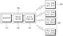
도 1에 도시된 바와 같이, 본 발명에 따른 통합형 배터리 장치(100)는, 충방전부(110), 충방전 제어부(120), 및 송수신 안테나부(130)를 구비한다.1, the integrated
상기 충방전부(110)는 충전 및 방전이 가능한 복수의 배터리 셀들을 구비한다. 상기 충방전부(110)에는 통상의 기술자에게 잘 알려진 충전 및 방전이 가능한 배터리 셀들이 구비된다.The charging and discharging
상기 충방전 제어부(120)는, 무선충전모드에서는 상기 송수신 안테나부(130)를 통해 무선수신되는 AC무선전력신호를 DC변환하여 상기 충방전부(110)에 충전되도록 제어하고, 무선방전모드에서는 상기 충방전부(110)에서 제공되는 DC전력신호를 AC변환하여 상기 송수신 안테나부(130)를 통해 AC무선전력신호로 무선송신되도록 제어하게 된다. 상기 충방전 제어부(120)의 다양한 실시예들은 도 2 내지 도 5를 통해 설명한다.In the wireless charging mode, the charging /
상기 송수신안테나부(130)는 AC 무선전력신호를 송신 및 수신하기 위한 무선전력용 안테나를 구비한다.The transceiving
상기 무선전력용 안테나는 전자기장에서 전자기 유도 원리에 따라 자기장 및 전자기파 형태의 신호를 송신 또는 수신할 수 있는 수동 소자로, 통상적으로 루프 안테나(loop antenna), 예를 들면, 루프 안테나의 다양한 유형 중 인쇄 회로 기판(printed circuit board) 형태의 루프 안테나가 이용될 수 있다. 인쇄 회로 기판 형태의 루프 안테나는 폴리에틸렌 테레프탈레이트 레진(PET, polyethylene Terephthalate resin) 또는 폴리이미드(PI, Polyimide ) 등의 박막 필름인 기판 상에 형성된 금속 피막을 에칭하거나 금속 박막을 프린팅함으로써 얻어질 수 있다.The wireless power antenna is a passive element capable of transmitting or receiving a signal in the form of a magnetic field and an electromagnetic wave in accordance with an electromagnetic induction principle in an electromagnetic field. The antenna is typically a loop antenna, for example, A loop antenna in the form of a printed circuit board may be used. The loop antenna in the form of a printed circuit board can be obtained by etching a metal film formed on a substrate which is a thin film of polyethylene terephthalate resin (PET) or polyimide (PI, polyimide) or by printing a metal thin film .
이외에도 통상의 기술자에게 잘 알려진 다양한 구조의 안테나가 이용되는 것이 가능하다.It is possible to use antennas of various structures well known to those of ordinary skill in the art.
본 발명에 따른 통합형 배터리 장치(100)는 상기 무선충전모드에서는 무선전력송신장치(200)로부터 전력을 무선수신하여 상기 충방전부(110)의 배터리셀들을 충전하게 되고, 상기 무선방전모드에서는 상기 충방전부(110)에 저장된 전력(에너지)를 상기 송수신 안테나부(130)를 통해 무선송신하여 하나 또는 복수의 무선전력수신장치들(300)에 제공하게 된다.In the wireless charging mode, the integrated
도 2 내지 도 5는 다양한 실시예의 충방전 제어부(120)를 가지는 통합형 배터리 장치(100)의 블록도들이다.2 to 5 are block diagrams of an integrated
도 2 내지 도 5는 송수신 안테나부(130)와 충방전부(110)의 구성을 포함하고 있으나, 그 구성은 도 1을 통해 설명한 바와 동일하므로 그 설명을 생략하고 상기 충방전 제어부(120)의 구성에 대해서만 설명하기로 한다.2 to 5 illustrate configurations of the transmission /
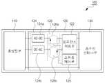
도 2는 상기 충방전 제어부(120)의 제1실시예를 가지는 통합형 배터리 장치(100)의 블록도이다.2 is a block diagram of an integrated
도 2에 도시된 바와 같이, 상기 충방전 제어부(120)의 제1실시예는, 임피던스 매칭부(122), 컨버팅부(124), 스위칭 제어부(125) 및 스위칭부(126)를 구비한다.As shown in FIG. 2, the first embodiment of the charging /
상기 임피던스 매칭부(122)는 상기 컨버팅부(124)와 상기 송수신 안테나부(130) 사이에 구비되어 상기 송수신 안테나부(130)와 상기 컨버팅부(124) 사이의 임피던스를 매칭(matching)시킨다.The impedance matching
상기 임피던스 매칭부(122)는 무선 충전 또는 방전을 위한 공진 주파수가 변경됨에 따라 가변적 또는 적응적으로 임피던스 매칭을 하기 위한 것이다. 즉, 상기 임피던스 매칭부(122)는 공진형 무선 전력 수신기 또는 무선전력 송신기의 위치에 따라 공진 주파수가 변경될 수 있는데, 그 위치를 바꾸지 않더라도 임피던스 매칭 회로 모듈을 통해 자동으로 그 무선 충전 또는 방전을 위한 공진 주파수를 변경하도록 구성된다. 상기 임피던스 매칭부(122)는 기본적으로 하나 또는 복수의 매칭 커패시터(matching capacitor)를 구비하고 이들 커패시터에 의해 공진 주파수가 변경될 수 있다.The impedance matching
상기 컨버팅부(124)는 상기 무선충전모드에서 상기 AC무선전력신호를 DC변환하여 상기 충방전부(110)에 제공하기 위한 제1컨버터(124a)와, 상기 무선방전모드에서 상기 충방전부(110)에서 제공되는 DC전력신호를 AC변환하여 상기 송수신 안테나부(130)에서 제공하는 제2컨버터(124b)를 구비할 수 있다. 상기 제1컨버터(124a)는 교류를 직류로 변환하는 AC-DC컨버터이고, 상기 제2컨버터(124b)는 직류를 교류로 변환하는 DC-AC컨버터일 수 있다.The converting
상기 스위칭부(126)는 상기 컨버팅부(124)와 상기 충방전부(110) 사이에 구비되며, 상기 무선충전모드의 선택을 위한 제1스위치(126a)와, 상기 무선방전모드의 선택을 위한 제2스위치(126b)를 구비한다.The
상기 제1스위치(126a) 및 상기 제2스위치(126b) 각각은 상기 스위칭 제어부(125)에 의해 턴 온 및 턴 오프가 제어되는 트랜지스터로 구성될 수 있다.Each of the
상기 스위칭 제어부(125)는 상기 무선충전모드 및 상기 무선방전모드의 선택을 위해 상기 스위칭부(126)를 제어한다. 상기 스위칭 제어부(125)는 CPU 또는 마이크로 컨트롤러를 구비하여 상기 스위칭부(126)에 대한 스위칭을 제어하게 된다.The
상기 스위칭 제어부(125)는 상기 충방전부(110)에 저장된 전력량, 근처에 무선전력 송신장치(200)가 존재하는 지 여부, 근처에 무선전력 수신장치(300)가 존재하는 지 여부 등에 따라 상기 스위칭부(126)를 제어하여 상기 무선충전모드 및 상기 무선방전모드를 자동으로 선택하는 것이 가능하다.The
예를 들어, 상기 충방전부(110)에 저장된 전력의 양이 미리 설정된 기준값보다 적은 경우는 상기 무선충전모드를 선택하도록 제어하고, 상기 기준값보다 많은 경우는 상기 무선방전모드를 선택하도록 할 수 있다. 이외에 근처에 무선전력 송신장치(200)가 존재하는 경우에는 상기 무선충전모드를 선택하고 근처에 무선전력 수신장치(300)가 존재하는 경우에는 자동으로 무선방전모드를 선택하도록 제어하는 것이 가능하다.For example, when the amount of power stored in the
도 3은 상기 충방전 제어부(120)의 제2실시예를 가지는 통합형 배터리 장치(100)의 블록도이다.3 is a block diagram of an integrated
도 3에 도시된 바와 같이, 상기 충방전 제어부(120)의 제2실시예는, 임피던스 매칭부(122), 컨버팅부(124), 스위칭 제어부(125) 및 스위칭부(126)를 구비한다.3, the second embodiment of the charging and discharging
상기 임피던스 매칭부(122)는 상기 컨버팅부(124)와 상기 송수신 안테나부(130) 사이에 구비되어 상기 송수신 안테나부(130)와 상기 컨버팅부(124) 사이의 임피던스를 매칭(matching)시킨다.The
상기 임피던스 매칭부(122)는 무선 충전 또는 방전을 위한 공진 주파수가 변경됨에 따라 가변적 또는 적응적으로 임피던스 매칭을 하기 위한 것이다. 즉, 상기 임피던스 매칭부(122)는 공진형 무선 전력 수신기 또는 무선전력 송신기의 위치에 따라 공진 주파수가 변경될 수 있는데, 그 위치를 바꾸지 않더라도 임피던스 매칭 회로 모듈을 통해 자동으로 그 무선 충전 또는 방전을 위한 공진 주파수를 변경하도록 구성된다. 상기 임피던스 매칭부(122)는 기본적으로 하나 또는 복수의 매칭 커패시터(matching capacitor)를 구비하고 이들 커패시터에 의해 공진 주파수가 변경될 수 있다.The
상기 컨버팅부(124)는 상기 무선충전모드에서 상기 AC무선전력신호를 DC변환하여 상기 충방전부(110)에 제공하기 위한 제1컨버터(124a)와, 상기 무선방전모드에서 상기 충방전부(110)에서 제공되는 DC전력신호를 AC변환하여 상기 송수신 안테나부(130)에서 제공하는 제2컨버터(124b)를 구비할 수 있다. 상기 제1컨버터(124a)는 교류를 직류로 변환하는 AC-DC컨버터이고, 상기 제2컨버터(124b)는 직류를 교류로 변환하는 DC-AC컨버터일 수 있다.The converting
상기 스위칭부(126)는 상기 컨버팅부(124)와 상기 임피던스 매칭부(122) 사이에 구비되며, 상기 무선충전모드의 선택을 위한 제1스위치(126a)와, 상기 무선방전모드의 선택을 위한 제2스위치(126b)를 구비한다.The
상기 제1스위치(126a) 및 상기 제2스위치(126b) 각각은 상기 스위칭 제어부(125)에 의해 턴 온 및 턴 오프가 제어되는 트랜지스터로 구성될 수 있다.Each of the
상기 스위칭 제어부(125)는 상기 무선충전모드 및 상기 무선방전모드의 선택을 위해 상기 스위칭부(126)를 제어한다. 상기 스위칭 제어부(125)는 CPU 또는 마이크로 컨트롤러를 구비하여 상기 스위칭부(126)에 대한 스위칭을 제어하게 된다.The switching
상기 스위칭 제어부(125)는 상기 충방전부(110)에 저장된 전력량, 근처에 무선전력 송신장치(200)가 존재하는 지 여부, 근처에 무선전력 수신장치(300)가 존재하는 지 여부 등에 따라 상기 스위칭부(126)를 제어하여 상기 무선충전모드 및 상기 무선방전모드를 자동으로 선택하는 것이 가능하다.The switching
예를 들어, 상기 충방전부(110)에 저장된 전력의 양이 미리 설정된 기준값보다 적은 경우는 상기 무선충전모드를 선택하도록 제어하고, 상기 기준값보다 많은 경우는 상기 무선방전모드를 선택하도록 할 수 있다. 이외에 근처에 무선전력 송신장치(200)가 존재하는 경우에는 상기 무선충전모드를 선택하고 근처에 무선전력 수신장치(300)가 존재하는 경우에는 자동으로 무선방전모드를 선택하도록 제어하는 것이 가능하다.For example, when the amount of power stored in the
도 4는 상기 충방전 제어부(120)의 제3실시예를 가지는 통합형 배터리 장치(100)의 블록도이다.4 is a block diagram of an
도 4에 도시된 바와 같이, 상기 충방전 제어부(120)의 제3실시예는, 임피던스 매칭부(122), 컨버팅부(124), 및 스위칭부(126)를 구비한다.4, the third embodiment of the charge and
상기 임피던스 매칭부(122)는 상기 컨버팅부(124)와 상기 송수신 안테나부(130) 사이에 구비되어 상기 송수신 안테나부(130)와 상기 컨버팅부(124) 사이의 임피던스를 매칭(matching)시킨다.The
상기 임피던스 매칭부(122)는 무선 충전 또는 방전을 위한 공진 주파수가 변경됨에 따라 가변적 또는 적응적으로 임피던스 매칭을 하기 위한 것이다. 즉, 상기 임피던스 매칭부(122)는 공진형 무선 전력 수신기 또는 무선전력 송신기의 위치에 따라 공진 주파수가 변경될 수 있는데, 그 위치를 바꾸지 않더라도 임피던스 매칭 회로 모듈을 통해 자동으로 그 무선 충전 또는 방전을 위한 공진 주파수를 변경하도록 구성된다. 상기 임피던스 매칭부(122)는 기본적으로 하나 또는 복수의 매칭 커패시터(matching capacitor)를 구비하고 이들 커패시터에 의해 공진 주파수가 변경될 수 있다.The
상기 컨버팅부(124)는 상기 무선충전모드에서 상기 AC무선전력신호를 DC변환하여 상기 충방전부(110)에 제공하기 위한 제1컨버터(124a)와, 상기 무선방전모드에서 상기 충방전부(110)에서 제공되는 DC전력신호를 AC변환하여 상기 송수신 안테나부(130)에서 제공하는 제2컨버터(124b)를 구비할 수 있다. 상기 제1컨버터(124a)는 교류를 직류로 변환하는 AC-DC컨버터이고, 상기 제2컨버터(124b)는 직류를 교류로 변환하는 DC-AC컨버터일 수 있다.The converting
상기 스위칭부(126)는 상기 컨버팅부(124)와 상기 충방전부(110) 사이에 구비되며, 상기 무선충전모드의 선택을 위한 제1스위치(126c)와, 상기 무선방전모드의 선택을 위한 제2스위치(126d)를 구비한다.The
상기 제1스위치(126c)는 애노드 단자가 상기 제1컨버터(124a)에 연결되고 캐소드 단자가 상기 충방전부(110)에 연결되는 다이오드 소자이고, 상기 제2스위치(126d)는 전력변화의 감지를 통해 무선방전모드를 결정하는 송신스위치 모듈(126d)을 구비할 수 있다.The
상기 제1스위치(126c)인 다이오드 소자는 상기 제1컨버터(124a)를 거친 수신전력이 상기 충방전부(110)로 전송되도록 하나 상기 충방전부(110)에 저장된 전력이 상기 제1스위치(126c)를 통해 방전되는 것을 차단하게 된다. 이에 따라 근처에 무선전력 송신장치(200)가 존재하고 상기 송수신 안테나부(130)를 통해 무선전력이 수신되는 경우에 상기 무선충전모드는 자동으로 선택되게 된다.The diode element serving as the
상기 제2스위치(126d)는 별도의 스위칭 제어부의 제어동작이나 별도의 컨트롤러의 제어동작없이 능동적으로 동작하게 된다. 예를 들면, 근처에 무선전력 수신장치(300)가 존재하는 경우에 상기 송수신 안테나부(130)의 송수신 안테나와 상기 무선전력 수신장치(300)가 전자기적 공진 결합 또는 전기적 결합을 하게 되면, 이에 따른 전력변화를 감지하여 무선방전모드로 능동적 스위칭 동작하게 된다.The
이에 따라 상기 제2스위치(126d)인 송신스위치 모듈(126d)은 전력변화의 감지를 위한 감지수단이나 전력변화에 의해 능동적인 스위칭 동작을 수행하는 모듈을 포함할 수 있다.Accordingly, the
도 5는 상기 충방전 제어부(120)의 제4실시예를 가지는 통합형 배터리 장치(100)의 블록도이다.5 is a block diagram of an
도 5에 도시된 바와 같이, 상기 충방전 제어부(120)의 제4실시예는, 임피던스 매칭부(122), 컨버팅부(124), 및 스위칭부(126)를 구비한다.As shown in FIG. 5, the fourth embodiment of the charge and
상기 임피던스 매칭부(122)는 상기 컨버팅부(124)와 상기 송수신 안테나부(130) 사이에 구비되어 상기 송수신 안테나부(130)와 상기 컨버팅부(124) 사이의 임피던스를 매칭(matching)시킨다.The
상기 임피던스 매칭부(122)는 무선 충전 또는 방전을 위한 공진 주파수가 변경됨에 따라 가변적 또는 적응적으로 임피던스 매칭을 하기 위한 것이다. 즉, 상기 임피던스 매칭부(122)는 공진형 무선 전력 수신기 또는 무선전력 송신기의 위치에 따라 공진 주파수가 변경될 수 있는데, 그 위치를 바꾸지 않더라도 임피던스 매칭 회로 모듈을 통해 자동으로 그 무선 충전 또는 방전을 위한 공진 주파수를 변경하도록 구성된다. 상기 임피던스 매칭부(122)는 기본적으로 하나 또는 복수의 매칭 커패시터(matching capacitor)를 구비하고 이들 커패시터에 의해 공진 주파수가 변경될 수 있다.The
상기 컨버팅부(124)는 상기 무선충전모드에서 상기 AC무선전력신호를 DC변환하여 상기 충방전부(110)에 제공하기 위한 제1컨버터(124a)와, 상기 무선방전모드에서 상기 충방전부(110)에서 제공되는 DC전력신호를 AC변환하여 상기 송수신 안테나부(130)에서 제공하는 제2컨버터(124b)를 구비할 수 있다. 상기 제1컨버터(124a)는 교류를 직류로 변환하는 AC-DC컨버터이고, 상기 제2컨버터(124b)는 직류를 교류로 변환하는 DC-AC컨버터일 수 있다.The converting
상기 스위칭부(126)는 상기 컨버팅부(124)와 상기 충방전부(110) 사이에 구비되며, 상기 무선충전모드의 선택을 위한 제1스위치(126e)와, 상기 무선방전모드의 선택을 위한 제2스위치(126f)를 구비한다.The
상기 제1스위치(126e) 및 상기 제2스위치(126f) 각각은 전력변화의 감지를 통해 무선충전모드 및 무선방전모드를 결정하는 능동스위치모듈을 구비할 수 있다.Each of the
상기 제1스위치(126e)인 능동수신스위치 모듈은 별도의 스위칭 제어부의 제어동작이나 별도의 컨트롤러의 제어동작없이 능동적으로 동작하게 된다, 예를 들면, 근처에 무선전력 송신장치(200)가 존재하고, 상기 송수신 안테나부(130)의 송수신 안테나와 상기 무선전력 송신장치(200)가 전자기적 공진 결합 또는 전기적 결합을 하게 되면, 이에 따른 전력변화를 감지하여 무선충전모드로 스위칭 동작하게 된다.The active receiving switch module as the
상기 제2스위치(126f)인 능동송신스위치 모듈은 별도의 스위칭 제어부의 제어동작이나 별도의 컨트롤러의 제어동작없이 능동적으로 동작하게 된다. 예를 들면, 근처에 무선전력 수신장치(300)가 존재하는 경우에 상기 송수신 안테나부(130)의 송수신 안테나와 상기 무선전력 수신장치(300)가 전자기적 공진 결합 또는 전기적 결합을 하게 되면, 이에 따른 전력변화를 감지하여 무선방전모드로 스위칭 동작하게 된다.The active transmission switch module, which is the
상기 제1스위치(126e) 및 상기 제2스위치(126f) 각각은 전력변화의 감지를 위한 감지수단이나 전력변화에 의해 능동적인 스위칭 동작을 수행하는 모듈을 포함할 수 있다.Each of the
본 발명에 적용되는 무선 전력 송수신 방식은 자기유도방식, 자기공명방식을 포함하여 통상의 기술자에게 잘 알려진 무선 전력 송수신 방식이 적용될 수 있다.The wireless power transmission / reception scheme applied to the present invention can be applied to a wireless power transmission / reception scheme well known to those of ordinary skill in the art, including a magnetic induction scheme and a magnetic resonance scheme.
또한, 본 발명에 적용되는 통합형 배터리 장치는 아래에서 설명되는 무선충전 및 무선방전 외에 유선 충전 및 유선방전도 가능한 구조를 가진다. 유선 충전 및 방전기술의 경우에는 통상의 기술자에게 잘 알려져 있으므로 더 이상의 설명을 생략한다.In addition, the integrated battery device according to the present invention has a structure capable of wired charging and wire discharge as well as wireless charging and wireless discharging described below. Wired charging and discharging techniques are well known to those of ordinary skill in the art and will not be described further herein.
본 발명에 따른 무선전력 충방전이 가능한 통합형 배터리 장치는 스마트폰 등의 모바일 기기를 위한 보조 배터리 장치 등으로 활용가능하고, 이외에 다양한 배터리 장치에 적용가능하다.The integrated battery device capable of charging and discharging wireless power according to the present invention can be utilized as an auxiliary battery device for mobile devices such as a smart phone and the like, and is also applicable to various battery devices.
본 발명에 따른 무선전력 충방전이 가능한 통합형 배터리 장치는 휴대가 가능하여 이동이 가능하면서도 무선전력 송신장치로부터 전력을 무선 수신하거나, 무선 전력 수신을 원하는 모바일 기기 등의 다수의 무선전력 수신장치에 전력을 무선송신할 수 있다는 장점이 있다.The integrated battery device capable of charging and discharging wireless power according to the present invention is capable of carrying and capable of wirelessly receiving electric power from a wireless power transmission device while being mobile and capable of powering a plurality of wireless power receiving devices such as a mobile device, Can be wirelessly transmitted.
상기한 실시예의 설명은 본 발명의 더욱 철저한 이해를 위하여 도면을 참조로 예를 든 것에 불과하므로, 본 발명을 한정하는 의미로 해석되어서는 안될 것이다. 또한, 본 발명이 속하는 기술 분야에서 통상의 지식을 가진 자에게 있어 본 발명의 기본적 원리를 벗어나지 않는 범위 내에서 다양한 변화와 변경이 가능함은 명백하다 할 것이다.The foregoing description of the embodiments is merely illustrative of the present invention with reference to the drawings for a more thorough understanding of the present invention, and thus should not be construed as limiting the present invention. It will be apparent to those skilled in the art that various changes and modifications may be made without departing from the basic principles of the present invention.
110 : 충방전부 120 : 충방전 제어부
130 : 송수신 안테나부110: charging part 120: charging / discharging control part
130: Transmitting /
Claims (5)
Translated fromKorean충전 및 방전이 가능한 복수의 배터리 셀들을 구비하는 충방전부와;
AC 무선전력신호를 송신 및 수신하기 위한 무선전력용 안테나를 구비하는 송수신 안테나부와;
무선충전모드에서는 상기 송수신 안테나부를 통해 무선수신되는 AC무선전력신호를 DC변환하여 상기 충방전부에 충전되도록 제어하고, 무선방전모드에서는 상기 충방전부에서 제공되는 DC전력신호를 AC변환하여 상기 송수신 안테나부를 통해 AC무선전력신호로 무선송신되도록 제어하는 충방전제어부를 구비하고,
상기 충방전 제어부는,
상기 무선충전모드에서 상기 AC무선전력신호를 DC변환하여 상기 충방전부에 제공하기 위한 제1컨버터와, 상기 무선방전모드에서 상기 충방전부에서 제공되는 DC전력신호를 AC변환하여 상기 송수신 안테나부에서 제공하는 제2컨버터를 구비하는 컨버팅부와;
상기 컨버팅부와 상기 송수신 안테나부 사이에 구비되어 상기 송수신 안테나부와 상기 컨버팅부 사이의 임피던스를 매칭(matching)시키는 임피던스 매칭부와;
상기 컨버팅부와 상기 임피던스 매칭부 사이 또는 상기 컨버팅부와 상기 충방전부 사이에 구비되며, 상기 무선충전모드의 선택을 위한 제1스위치와, 상기 무선방전모드의 선택을 위한 제2스위치를 구비하는 스위칭부를 구비하며,
상기 제1스위치는 애노드 단자가 상기 제1컨버터에 연결되고 캐소드 단자가 상기 충방전부에 연결되는 다이오드 소자이고,
상기 제2스위치는 전력변화의 감지를 통해 무선방전모드를 결정하는 송신스위치 모듈을 구비하고,
상기 송신스위치 모듈은,
상기 송수신 안테나부와 무선전력 수신장치의 전자기적 공진 결합 또는 전기적 결합에 따른 전력변화를 감지하는 감지수단 및 상기 감지수단에 의해 온오프되는 스위치로 구성됨을 특징으로 하는 무선전력 충방전이 가능한 통합형 배터리 장치.An integrated battery device capable of wireless power charging and discharging, comprising:
A charging unit having a plurality of battery cells capable of charging and discharging;
A transmitting and receiving antenna unit having a wireless power antenna for transmitting and receiving an AC wireless power signal;
In the wireless charging mode, the DC power signal received through the transmission and reception antenna unit is DC-converted to be charged in the charging unit. In the radio discharging mode, the DC power signal provided from the charging unit is AC- And a charge / discharge control unit for controlling the radio transmission unit to wirelessly transmit the AC wireless power signal,
The charge /
A first converter for DC-converting the AC wireless power signal in the wireless charging mode and providing the DC power signal to the charging and discharging unit; and a controller for AC-converting the DC power signal provided from the charging and discharging unit in the wireless discharging mode, A second converter for converting the output signal of the first converter into a digital signal;
An impedance matching unit provided between the converting unit and the transmitting and receiving antenna unit to match an impedance between the transmitting and receiving antenna unit and the converting unit;
A switching unit provided between the converting unit and the impedance matching unit or between the converting unit and the charging unit and including a first switch for selecting the wireless charging mode and a second switch for selecting the wireless discharging mode, And,
The first switch is a diode element in which an anode terminal is connected to the first converter and a cathode terminal is connected to the charging part,
Wherein the second switch includes a transmission switch module for determining a radio discharge mode through detection of a power change,
The transmission switch module includes:
And a switch that is turned on and off by the sensing unit. The wireless power charging / discharging device according to claim 1, further comprising: a sensing unit that senses a power change due to an electromagnetic resonance coupling or an electrical coupling between the transmitting and receiving antenna unit and the wireless power receiving apparatus; Device.
충전 및 방전이 가능한 복수의 배터리 셀들을 구비하는 충방전부와;
AC 무선전력신호를 송신 및 수신하기 위한 무선전력용 안테나를 구비하는 송수신 안테나부와;
무선충전모드에서는 상기 송수신 안테나부를 통해 무선수신되는 AC무선전력신호를 DC변환하여 상기 충방전부에 충전되도록 제어하고, 무선방전모드에서는 상기 충방전부에서 제공되는 DC전력신호를 AC변환하여 상기 송수신 안테나부를 통해 AC무선전력신호로 무선송신되도록 제어하는 충방전제어부를 구비하고,
상기 충방전 제어부는,
상기 무선충전모드에서 상기 AC무선전력신호를 DC변환하여 상기 충방전부에 제공하기 위한 제1컨버터와, 상기 무선방전모드에서 상기 충방전부에서 제공되는 DC전력신호를 AC변환하여 상기 송수신 안테나부에서 제공하는 제2컨버터를 구비하는 컨버팅부와;
상기 컨버팅부와 상기 송수신 안테나부 사이에 구비되어 상기 송수신 안테나부와 상기 컨버팅부 사이의 임피던스를 매칭(matching)시키는 임피던스 매칭부와;
상기 컨버팅부와 상기 임피던스 매칭부 사이 또는 상기 컨버팅부와 상기 충방전부 사이에 구비되며, 상기 무선충전모드의 선택을 위한 제1스위치와, 상기 무선방전모드의 선택을 위한 제2스위치를 구비하는 스위칭부를 구비하며,
상기 제1스위치 및 상기 제2스위치 각각은 전력변화의 감지를 통해 무선충전모드 및 무선방전모드를 결정하는 능동스위치모듈을 구비하고,
상기 능동스위치 모듈은, 무선전력 송신장치 또는 무선전력수신장치와 상기 송수신 안테나부의 전자기적 공진 결합 또는 전기적 결합에 따른 전력변화를 감지하는 감지수단 및 상기 감지수단에 의해 온오프되는 스위치로 구성됨을 특징으로 하는 무선전력 충방전이 가능한 통합형 배터리 장치.An integrated battery device capable of wireless power charging and discharging, comprising:
A charging unit having a plurality of battery cells capable of charging and discharging;
A transmitting and receiving antenna unit having a wireless power antenna for transmitting and receiving an AC wireless power signal;
In the wireless charging mode, the DC power signal received through the transmission / reception antenna unit is DC-converted to be charged in the charging / discharging unit. In the radio discharging mode, the DC power signal provided from the charging / And a charge / discharge control unit for controlling the radio transmission unit to wirelessly transmit the AC wireless power signal,
The charge /
A first converter for DC-converting the AC wireless power signal in the wireless charging mode and providing the DC power signal to the charging and discharging unit; and a controller for AC-converting the DC power signal provided from the charging and discharging unit in the wireless discharging mode, A second converter for converting the output signal of the first converter into a digital signal;
An impedance matching unit provided between the converting unit and the transmitting and receiving antenna unit to match an impedance between the transmitting and receiving antenna unit and the converting unit;
A switching unit provided between the converting unit and the impedance matching unit or between the converting unit and the charging unit and including a first switch for selecting the wireless charging mode and a second switch for selecting the wireless discharging mode, And,
Wherein each of the first switch and the second switch includes an active switch module for determining a wireless charging mode and a radioactive discharge mode through detection of a change in power,
The active switch module may include a sensing unit that senses a power change due to an electromagnetic resonance coupling or an electrical coupling between the wireless power transmitting device or the wireless power receiving device and the transmitting and receiving antenna unit, and a switch that is turned on and off by the sensing unit. And an integrated battery device capable of charging and discharging wireless power.
Priority Applications (1)
| Application Number | Priority Date | Filing Date | Title |
|---|---|---|---|
| KR1020160082301AKR101719205B1 (en) | 2016-06-30 | 2016-06-30 | Battery apparatus for charging and discharging of wireless power |
Applications Claiming Priority (1)
| Application Number | Priority Date | Filing Date | Title |
|---|---|---|---|
| KR1020160082301AKR101719205B1 (en) | 2016-06-30 | 2016-06-30 | Battery apparatus for charging and discharging of wireless power |
Publications (1)
| Publication Number | Publication Date |
|---|---|
| KR101719205B1true KR101719205B1 (en) | 2017-03-31 |
Family
ID=58501013
Family Applications (1)
| Application Number | Title | Priority Date | Filing Date |
|---|---|---|---|
| KR1020160082301AExpired - Fee RelatedKR101719205B1 (en) | 2016-06-30 | 2016-06-30 | Battery apparatus for charging and discharging of wireless power |
Country Status (1)
| Country | Link |
|---|---|
| KR (1) | KR101719205B1 (en) |
Cited By (3)
| Publication number | Priority date | Publication date | Assignee | Title |
|---|---|---|---|---|
| CN110957816A (en)* | 2018-09-26 | 2020-04-03 | 紫光同芯微电子有限公司 | A device system enabling a battery to have wireless charging reception capability |
| CN110957813A (en)* | 2018-09-26 | 2020-04-03 | 紫光同芯微电子有限公司 | A device system for enabling batteries to have wireless charging and transmitting capabilities |
| CN115923513A (en)* | 2022-12-13 | 2023-04-07 | 合众新能源汽车股份有限公司 | Wireless discharge system |
Citations (3)
| Publication number | Priority date | Publication date | Assignee | Title |
|---|---|---|---|---|
| KR20130032293A (en)* | 2012-12-07 | 2013-04-01 | 엘지이노텍 주식회사 | A wireless power reception apparatus and a wireless charging system using the same |
| KR101491472B1 (en) | 2013-09-12 | 2015-02-11 | 희성전자 주식회사 | Antenna Apparatusfor Wireless Power Transfer |
| KR20150073275A (en)* | 2013-12-20 | 2015-07-01 | 삼성전기주식회사 | Apparatus for transmitting and receiving wireless power |
- 2016
- 2016-06-30KRKR1020160082301Apatent/KR101719205B1/ennot_activeExpired - Fee Related
Patent Citations (3)
| Publication number | Priority date | Publication date | Assignee | Title |
|---|---|---|---|---|
| KR20130032293A (en)* | 2012-12-07 | 2013-04-01 | 엘지이노텍 주식회사 | A wireless power reception apparatus and a wireless charging system using the same |
| KR101491472B1 (en) | 2013-09-12 | 2015-02-11 | 희성전자 주식회사 | Antenna Apparatusfor Wireless Power Transfer |
| KR20150073275A (en)* | 2013-12-20 | 2015-07-01 | 삼성전기주식회사 | Apparatus for transmitting and receiving wireless power |
Cited By (3)
| Publication number | Priority date | Publication date | Assignee | Title |
|---|---|---|---|---|
| CN110957816A (en)* | 2018-09-26 | 2020-04-03 | 紫光同芯微电子有限公司 | A device system enabling a battery to have wireless charging reception capability |
| CN110957813A (en)* | 2018-09-26 | 2020-04-03 | 紫光同芯微电子有限公司 | A device system for enabling batteries to have wireless charging and transmitting capabilities |
| CN115923513A (en)* | 2022-12-13 | 2023-04-07 | 合众新能源汽车股份有限公司 | Wireless discharge system |
Similar Documents
| Publication | Publication Date | Title |
|---|---|---|
| US11303135B2 (en) | Wireless power transmitter for excluding cross-connected wireless power receiver and method for controlling the same | |
| US10211678B2 (en) | Wireless charging apparatus and wireless charging method | |
| US10587123B2 (en) | Wireless power transmitter for excluding cross-connected wireless power receiver and method for controlling the same | |
| US9812893B2 (en) | Wireless power receiver | |
| US9191075B2 (en) | Wireless power control method, system, and apparatus utilizing a wakeup signal to prevent standby power consumption | |
| KR101824414B1 (en) | Electric power transmitting device, electric power receiving device, and power supply method using electric power transmitting and receiving devices | |
| KR101933462B1 (en) | Wireless power receiver for controlling magnitude of wireless power | |
| KR101854420B1 (en) | Power transmission device and wireless power transmission system including the same | |
| KR101958755B1 (en) | Wireless power receiver and method for controlling thereof | |
| JP2018198535A (en) | Non-contact power transmission device | |
| US9847675B2 (en) | Power receiving device and power feeding system | |
| KR20130024320A (en) | Wireless power transmission system using solar cell module | |
| KR20140032631A (en) | Method and apparatus for communication and power control in magnetic resonant wireless power transfer system | |
| KR20150050027A (en) | Wireless charging device and controlling method thereof | |
| KR20130023618A (en) | Wireless power transmission system and control method thereof | |
| US20140159673A1 (en) | Wireless charging apparatus and method | |
| KR101719205B1 (en) | Battery apparatus for charging and discharging of wireless power | |
| KR101712647B1 (en) | Auxiliary battery for wirelessly charging and discharging | |
| JP4823259B2 (en) | Electronic circuit, wireless terminal and wireless terminal system | |
| KR101171938B1 (en) | Multi-node wireless power transmission system and charging method therof using magnetic resonance induction | |
| JP2019092251A (en) | Power reception apparatus and wireless power transmission system | |
| KR101946848B1 (en) | Wireless power receiver | |
| KR20190014614A (en) | Sensing System and Method, Portable Terminal Using the Same | |
| KR102040726B1 (en) | Resonant apparatus for wireless power transfer | |
| JP2007174797A (en) | Charger and portable electronic equipment |
Legal Events
| Date | Code | Title | Description |
|---|---|---|---|
| PA0109 | Patent application | St.27 status event code:A-0-1-A10-A12-nap-PA0109 | |
| PA0201 | Request for examination | St.27 status event code:A-1-2-D10-D11-exm-PA0201 | |
| D13-X000 | Search requested | St.27 status event code:A-1-2-D10-D13-srh-X000 | |
| P11-X000 | Amendment of application requested | St.27 status event code:A-2-2-P10-P11-nap-X000 | |
| P13-X000 | Application amended | St.27 status event code:A-2-2-P10-P13-nap-X000 | |
| R15-X000 | Change to inventor requested | St.27 status event code:A-3-3-R10-R15-oth-X000 | |
| R16-X000 | Change to inventor recorded | St.27 status event code:A-3-3-R10-R16-oth-X000 | |
| D14-X000 | Search report completed | St.27 status event code:A-1-2-D10-D14-srh-X000 | |
| PE0902 | Notice of grounds for rejection | St.27 status event code:A-1-2-D10-D21-exm-PE0902 | |
| E13-X000 | Pre-grant limitation requested | St.27 status event code:A-2-3-E10-E13-lim-X000 | |
| P11-X000 | Amendment of application requested | St.27 status event code:A-2-2-P10-P11-nap-X000 | |
| P13-X000 | Application amended | St.27 status event code:A-2-2-P10-P13-nap-X000 | |
| PE0701 | Decision of registration | St.27 status event code:A-1-2-D10-D22-exm-PE0701 | |
| GRNT | Written decision to grant | ||
| PR0701 | Registration of establishment | St.27 status event code:A-2-4-F10-F11-exm-PR0701 | |
| PR1002 | Payment of registration fee | St.27 status event code:A-2-2-U10-U11-oth-PR1002 Fee payment year number:1 | |
| PG1601 | Publication of registration | St.27 status event code:A-4-4-Q10-Q13-nap-PG1601 | |
| R18-X000 | Changes to party contact information recorded | St.27 status event code:A-5-5-R10-R18-oth-X000 | |
| S20-X000 | Security interest recorded | St.27 status event code:A-4-4-S10-S20-lic-X000 | |
| P22-X000 | Classification modified | St.27 status event code:A-4-4-P10-P22-nap-X000 | |
| R18-X000 | Changes to party contact information recorded | St.27 status event code:A-5-5-R10-R18-oth-X000 | |
| P22-X000 | Classification modified | St.27 status event code:A-4-4-P10-P22-nap-X000 | |
| FPAY | Annual fee payment | Payment date:20200203 Year of fee payment:4 | |
| PR1001 | Payment of annual fee | St.27 status event code:A-4-4-U10-U11-oth-PR1001 Fee payment year number:4 | |
| PR1001 | Payment of annual fee | St.27 status event code:A-4-4-U10-U11-oth-PR1001 Fee payment year number:5 | |
| P22-X000 | Classification modified | St.27 status event code:A-4-4-P10-P22-nap-X000 | |
| PR1001 | Payment of annual fee | St.27 status event code:A-4-4-U10-U11-oth-PR1001 Fee payment year number:6 | |
| PC1903 | Unpaid annual fee | St.27 status event code:A-4-4-U10-U13-oth-PC1903 Not in force date:20230318 Payment event data comment text:Termination Category : DEFAULT_OF_REGISTRATION_FEE | |
| PC1903 | Unpaid annual fee | St.27 status event code:N-4-6-H10-H13-oth-PC1903 Ip right cessation event data comment text:Termination Category : DEFAULT_OF_REGISTRATION_FEE Not in force date:20230318 |