KR101719097B1 - Polishing head, chemical-mechanical polishing system and method for polishing substrate - Google Patents
Polishing head, chemical-mechanical polishing system and method for polishing substrateDownload PDFInfo
- Publication number
- KR101719097B1 KR101719097B1KR1020160019176AKR20160019176AKR101719097B1KR 101719097 B1KR101719097 B1KR 101719097B1KR 1020160019176 AKR1020160019176 AKR 1020160019176AKR 20160019176 AKR20160019176 AKR 20160019176AKR 101719097 B1KR101719097 B1KR 101719097B1
- Authority
- KR
- South Korea
- Prior art keywords
- substrate
- polishing
- pressure
- carrier head
- pressure units
- Prior art date
- Legal status (The legal status is an assumption and is not a legal conclusion. Google has not performed a legal analysis and makes no representation as to the accuracy of the status listed.)
- Active
Links
Images


Classifications
- H—ELECTRICITY
- H01—ELECTRIC ELEMENTS
- H01L—SEMICONDUCTOR DEVICES NOT COVERED BY CLASS H10
- H01L21/00—Processes or apparatus adapted for the manufacture or treatment of semiconductor or solid state devices or of parts thereof
- H01L21/02—Manufacture or treatment of semiconductor devices or of parts thereof
- H01L21/04—Manufacture or treatment of semiconductor devices or of parts thereof the devices having potential barriers, e.g. a PN junction, depletion layer or carrier concentration layer
- H01L21/18—Manufacture or treatment of semiconductor devices or of parts thereof the devices having potential barriers, e.g. a PN junction, depletion layer or carrier concentration layer the devices having semiconductor bodies comprising elements of Group IV of the Periodic Table or AIIIBV compounds with or without impurities, e.g. doping materials
- H01L21/30—Treatment of semiconductor bodies using processes or apparatus not provided for in groups H01L21/20 - H01L21/26
- H01L21/302—Treatment of semiconductor bodies using processes or apparatus not provided for in groups H01L21/20 - H01L21/26 to change their surface-physical characteristics or shape, e.g. etching, polishing, cutting
- H01L21/304—Mechanical treatment, e.g. grinding, polishing, cutting
- B—PERFORMING OPERATIONS; TRANSPORTING
- B24—GRINDING; POLISHING
- B24B—MACHINES, DEVICES, OR PROCESSES FOR GRINDING OR POLISHING; DRESSING OR CONDITIONING OF ABRADING SURFACES; FEEDING OF GRINDING, POLISHING, OR LAPPING AGENTS
- B24B37/00—Lapping machines or devices; Accessories
- B24B37/11—Lapping tools
- B24B37/20—Lapping pads for working plane surfaces
- B24B37/26—Lapping pads for working plane surfaces characterised by the shape of the lapping pad surface, e.g. grooved
- B—PERFORMING OPERATIONS; TRANSPORTING
- B24—GRINDING; POLISHING
- B24B—MACHINES, DEVICES, OR PROCESSES FOR GRINDING OR POLISHING; DRESSING OR CONDITIONING OF ABRADING SURFACES; FEEDING OF GRINDING, POLISHING, OR LAPPING AGENTS
- B24B37/00—Lapping machines or devices; Accessories
- B24B37/04—Lapping machines or devices; Accessories designed for working plane surfaces
- B24B37/07—Lapping machines or devices; Accessories designed for working plane surfaces characterised by the movement of the work or lapping tool
- B24B37/10—Lapping machines or devices; Accessories designed for working plane surfaces characterised by the movement of the work or lapping tool for single side lapping
- B—PERFORMING OPERATIONS; TRANSPORTING
- B24—GRINDING; POLISHING
- B24B—MACHINES, DEVICES, OR PROCESSES FOR GRINDING OR POLISHING; DRESSING OR CONDITIONING OF ABRADING SURFACES; FEEDING OF GRINDING, POLISHING, OR LAPPING AGENTS
- B24B37/00—Lapping machines or devices; Accessories
- B24B37/27—Work carriers
- B24B37/30—Work carriers for single side lapping of plane surfaces
- B—PERFORMING OPERATIONS; TRANSPORTING
- B24—GRINDING; POLISHING
- B24B—MACHINES, DEVICES, OR PROCESSES FOR GRINDING OR POLISHING; DRESSING OR CONDITIONING OF ABRADING SURFACES; FEEDING OF GRINDING, POLISHING, OR LAPPING AGENTS
- B24B37/00—Lapping machines or devices; Accessories
- B24B37/34—Accessories
- B—PERFORMING OPERATIONS; TRANSPORTING
- B24—GRINDING; POLISHING
- B24B—MACHINES, DEVICES, OR PROCESSES FOR GRINDING OR POLISHING; DRESSING OR CONDITIONING OF ABRADING SURFACES; FEEDING OF GRINDING, POLISHING, OR LAPPING AGENTS
- B24B49/00—Measuring or gauging equipment for controlling the feed movement of the grinding tool or work; Arrangements of indicating or measuring equipment, e.g. for indicating the start of the grinding operation
- B24B49/10—Measuring or gauging equipment for controlling the feed movement of the grinding tool or work; Arrangements of indicating or measuring equipment, e.g. for indicating the start of the grinding operation involving electrical means
- B—PERFORMING OPERATIONS; TRANSPORTING
- B24—GRINDING; POLISHING
- B24B—MACHINES, DEVICES, OR PROCESSES FOR GRINDING OR POLISHING; DRESSING OR CONDITIONING OF ABRADING SURFACES; FEEDING OF GRINDING, POLISHING, OR LAPPING AGENTS
- B24B49/00—Measuring or gauging equipment for controlling the feed movement of the grinding tool or work; Arrangements of indicating or measuring equipment, e.g. for indicating the start of the grinding operation
- B24B49/16—Measuring or gauging equipment for controlling the feed movement of the grinding tool or work; Arrangements of indicating or measuring equipment, e.g. for indicating the start of the grinding operation taking regard of the load
- B—PERFORMING OPERATIONS; TRANSPORTING
- B24—GRINDING; POLISHING
- B24B—MACHINES, DEVICES, OR PROCESSES FOR GRINDING OR POLISHING; DRESSING OR CONDITIONING OF ABRADING SURFACES; FEEDING OF GRINDING, POLISHING, OR LAPPING AGENTS
- B24B57/00—Devices for feeding, applying, grading or recovering grinding, polishing or lapping agents
- B24B57/02—Devices for feeding, applying, grading or recovering grinding, polishing or lapping agents for feeding of fluid, sprayed, pulverised, or liquefied grinding, polishing or lapping agents
- H—ELECTRICITY
- H01—ELECTRIC ELEMENTS
- H01L—SEMICONDUCTOR DEVICES NOT COVERED BY CLASS H10
- H01L21/00—Processes or apparatus adapted for the manufacture or treatment of semiconductor or solid state devices or of parts thereof
- H01L21/02—Manufacture or treatment of semiconductor devices or of parts thereof
- H01L21/04—Manufacture or treatment of semiconductor devices or of parts thereof the devices having potential barriers, e.g. a PN junction, depletion layer or carrier concentration layer
- H01L21/18—Manufacture or treatment of semiconductor devices or of parts thereof the devices having potential barriers, e.g. a PN junction, depletion layer or carrier concentration layer the devices having semiconductor bodies comprising elements of Group IV of the Periodic Table or AIIIBV compounds with or without impurities, e.g. doping materials
- H01L21/30—Treatment of semiconductor bodies using processes or apparatus not provided for in groups H01L21/20 - H01L21/26
- H01L21/302—Treatment of semiconductor bodies using processes or apparatus not provided for in groups H01L21/20 - H01L21/26 to change their surface-physical characteristics or shape, e.g. etching, polishing, cutting
- H01L21/306—Chemical or electrical treatment, e.g. electrolytic etching
- H01L21/30625—With simultaneous mechanical treatment, e.g. mechanico-chemical polishing
- H—ELECTRICITY
- H01—ELECTRIC ELEMENTS
- H01L—SEMICONDUCTOR DEVICES NOT COVERED BY CLASS H10
- H01L21/00—Processes or apparatus adapted for the manufacture or treatment of semiconductor or solid state devices or of parts thereof
- H01L21/02—Manufacture or treatment of semiconductor devices or of parts thereof
- H01L21/04—Manufacture or treatment of semiconductor devices or of parts thereof the devices having potential barriers, e.g. a PN junction, depletion layer or carrier concentration layer
- H01L21/18—Manufacture or treatment of semiconductor devices or of parts thereof the devices having potential barriers, e.g. a PN junction, depletion layer or carrier concentration layer the devices having semiconductor bodies comprising elements of Group IV of the Periodic Table or AIIIBV compounds with or without impurities, e.g. doping materials
- H01L21/30—Treatment of semiconductor bodies using processes or apparatus not provided for in groups H01L21/20 - H01L21/26
- H01L21/31—Treatment of semiconductor bodies using processes or apparatus not provided for in groups H01L21/20 - H01L21/26 to form insulating layers thereon, e.g. for masking or by using photolithographic techniques; After treatment of these layers; Selection of materials for these layers
- H01L21/3205—Deposition of non-insulating-, e.g. conductive- or resistive-, layers on insulating layers; After-treatment of these layers
- H01L21/321—After treatment
- H01L21/32115—Planarisation
- H01L21/3212—Planarisation by chemical mechanical polishing [CMP]
- H—ELECTRICITY
- H01—ELECTRIC ELEMENTS
- H01L—SEMICONDUCTOR DEVICES NOT COVERED BY CLASS H10
- H01L21/00—Processes or apparatus adapted for the manufacture or treatment of semiconductor or solid state devices or of parts thereof
- H01L21/02—Manufacture or treatment of semiconductor devices or of parts thereof
- H01L21/04—Manufacture or treatment of semiconductor devices or of parts thereof the devices having potential barriers, e.g. a PN junction, depletion layer or carrier concentration layer
- H01L21/34—Manufacture or treatment of semiconductor devices or of parts thereof the devices having potential barriers, e.g. a PN junction, depletion layer or carrier concentration layer the devices having semiconductor bodies not provided for in groups H01L21/18, H10D48/04 and H10D48/07, with or without impurities, e.g. doping materials
- H01L21/46—Treatment of semiconductor bodies using processes or apparatus not provided for in groups H01L21/428
- H01L21/461—Treatment of semiconductor bodies using processes or apparatus not provided for in groups H01L21/428 to change their surface-physical characteristics or shape, e.g. etching, polishing, cutting
- H—ELECTRICITY
- H01—ELECTRIC ELEMENTS
- H01L—SEMICONDUCTOR DEVICES NOT COVERED BY CLASS H10
- H01L21/00—Processes or apparatus adapted for the manufacture or treatment of semiconductor or solid state devices or of parts thereof
- H01L21/67—Apparatus specially adapted for handling semiconductor or electric solid state devices during manufacture or treatment thereof; Apparatus specially adapted for handling wafers during manufacture or treatment of semiconductor or electric solid state devices or components ; Apparatus not specifically provided for elsewhere
- H01L21/67005—Apparatus not specifically provided for elsewhere
- H01L21/67011—Apparatus for manufacture or treatment
- H01L21/67155—Apparatus for manufacturing or treating in a plurality of work-stations
- H01L21/67207—Apparatus for manufacturing or treating in a plurality of work-stations comprising a chamber adapted to a particular process
- H01L21/67219—Apparatus for manufacturing or treating in a plurality of work-stations comprising a chamber adapted to a particular process comprising at least one polishing chamber
- H—ELECTRICITY
- H01—ELECTRIC ELEMENTS
- H01L—SEMICONDUCTOR DEVICES NOT COVERED BY CLASS H10
- H01L21/00—Processes or apparatus adapted for the manufacture or treatment of semiconductor or solid state devices or of parts thereof
- H01L21/02—Manufacture or treatment of semiconductor devices or of parts thereof
- H01L21/04—Manufacture or treatment of semiconductor devices or of parts thereof the devices having potential barriers, e.g. a PN junction, depletion layer or carrier concentration layer
- H01L21/50—Assembly of semiconductor devices using processes or apparatus not provided for in a single one of the groups H01L21/18 - H01L21/326 or H10D48/04 - H10D48/07 e.g. sealing of a cap to a base of a container
- H01L21/60—Attaching or detaching leads or other conductive members, to be used for carrying current to or from the device in operation
- H01L2021/60007—Attaching or detaching leads or other conductive members, to be used for carrying current to or from the device in operation involving a soldering or an alloying process
- H01L2021/60022—Attaching or detaching leads or other conductive members, to be used for carrying current to or from the device in operation involving a soldering or an alloying process using bump connectors, e.g. for flip chip mounting
- H01L2021/60097—Applying energy, e.g. for the soldering or alloying process
- H01L2021/60172—Applying energy, e.g. for the soldering or alloying process using static pressure
Landscapes
- Engineering & Computer Science (AREA)
- Mechanical Engineering (AREA)
- Finish Polishing, Edge Sharpening, And Grinding By Specific Grinding Devices (AREA)
- Mechanical Treatment Of Semiconductor (AREA)
- Physics & Mathematics (AREA)
- Condensed Matter Physics & Semiconductors (AREA)
- General Physics & Mathematics (AREA)
- Manufacturing & Machinery (AREA)
- Computer Hardware Design (AREA)
- Microelectronics & Electronic Packaging (AREA)
- Power Engineering (AREA)
Abstract
Translated fromKorean
Description
Translated fromKorean본 발명은, 연마 헤드, 화학 기계적 연마 시스템 및 기판 연마 방법에 관한 것이다.The present invention relates to a polishing head, a chemical mechanical polishing system, and a substrate polishing method.
화학 기계적 연마(CMP; Chemical-Mechanical Polishing)는, 기판을 평탄화(flattening)하기 위해 연마성이고 부식성인 슬러리 및 연마 패드가 함께 화학적 방법 및 기계적 방법 양자 모두로 작용하는 프로세스이다. 일반적으로, CMP 시스템의 연마 헤드의 현재의 디자인은 그 연마 프로파일에 대한 제어를 가능하게 한다. 그러나, 연마 프로파일의 비대칭 형태(asymmetric topography)는 여전히 존재한다.Chemical-mechanical polishing (CMP) is a process in which both abrasive and corrosive slurries and polishing pads act together in both chemical and mechanical ways to flatten the substrate. In general, the current design of a polishing head of a CMP system enables control over its polishing profile. However, the asymmetric topography of the abrasive profile still exists.
본 발명의 목적은, 연마 헤드, 화학 기계적 연마 시스템 및 기판 연마 방법을 제공하는 것이다.It is an object of the present invention to provide a polishing head, a chemical mechanical polishing system and a substrate polishing method.
본 발명의 일 실시예에 따르면, 화학 기계적 연마 시스템을 위한 연마 헤드로서,According to one embodiment of the present invention, there is provided a polishing head for a chemical mechanical polishing system,
캐리어 헤드; 및Carrier head; And
캐리어 헤드 상에 배치되는 복수 개의 압력 유닛으로서, 압력 유닛들 중 적어도 2개는 캐리어 헤드의 중심 축선에 대해 동일한 둘레방향 라인 상에 위치하게 되는 것인 복수 개의 압력 유닛A plurality of pressure units disposed on the carrier head, wherein at least two of the pressure units are located on the same circumferential line with respect to the central axis of the carrier head;
을 포함하는 연마 헤드가 제공된다.Is provided.
본 발명에 따른 일 실시예에 따르면, 화학 기계적 연마 시스템으로서,According to an embodiment of the present invention, there is provided a chemical mechanical polishing system comprising:
연마 헤드로서,As a polishing head,
캐리어 헤드; 및Carrier head; And
캐리어 헤드 상에 배치되는 복수 개의 압력 유닛으로서, 압력 유닛들은 캐리어 헤드의 중심 축선에 대해 적어도 하나의 둘레방향 라인을 따라 적어도 부분적으로 배치되는 것인 복수 개의 압력 유닛A plurality of pressure units disposed on the carrier head, wherein the pressure units are disposed at least partially along at least one circumferential line with respect to the central axis of the carrier head,
을 포함하는 연마 헤드;A polishing head;
연마 헤드 아래에 배치되는 플레튼(platen); 및A platen disposed under the polishing head; And
플레튼 위에 배치되는 슬러리 도입 메커니즘Slurry introduction mechanism placed on the platens
을 포함하는 것인 화학 기계적 연마 시스템이 제공된다.A chemical mechanical polishing system is provided.
본 발명의 일 실시예에 따르면, 기판을 연마하는 방법으로서,According to an embodiment of the present invention, there is provided a method of polishing a substrate,
연마 패드 상에 슬러리를 공급하는 단계;Feeding the slurry onto a polishing pad;
연마 패드에 대해 기판을 유지하는 단계;Maintaining the substrate relative to the polishing pad;
기판의 중심 축선에 대해 동일한 둘레방향 라인 상에 위치하게 되는 적어도 2개의 압력 유닛을 개별적으로 작동시키는 단계; 및Separately operating at least two pressure units located on the same circumferential line with respect to the central axis of the substrate; And
연마 패드 및 기판 양자 모두를 회전시키는 단계Rotating both the polishing pad and the substrate
를 포함하는 방법이 제공된다.Is provided.
본 발명에 따르면, 연마 헤드, 화학 기계적 연마 시스템 및 기판 연마 방법을 얻을 수 있다.According to the present invention, a polishing head, a chemical mechanical polishing system, and a substrate polishing method can be obtained.
도 1은 본 개시내용의 일부 실시예에 따른 화학 기계적 연마 시스템의 개략도이다.
도 2는 도 1의 멤브레인의 상면도이다.
도 3은 도 1에서의 캐리어 헤드(carrier head)의 하면도이다.
도 4는 도 2에서의 라인 B-B'를 따라 취한, 멤브레인의 부분 단면도이다.
도 5는 본 개시내용의 일부 실시예에 따른 멤브레인의 부분 단면도이다.
도 6은 압전 층 및 기판의 확대 단면도이다.
도 7은 본 개시내용의 일부 실시예에 따른 연마 패드의 부분 단면도이다.
도 8은 본 개시내용의 일부 실시예에 따른 멤브레인의 상면도이다.
도 9는 본 개시내용의 일부 실시예에 따른 멤브레인의 상면도이다.
도 10은 본 개시내용의 일부 실시예에 따른 멤브레인의 상면도이다.1 is a schematic diagram of a chemical mechanical polishing system in accordance with some embodiments of the present disclosure;
Figure 2 is a top view of the membrane of Figure 1;
Figure 3 is a bottom view of the carrier head in Figure 1;
Figure 4 is a partial cross-sectional view of the membrane taken along line B-B 'in Figure 2;
5 is a partial cross-sectional view of a membrane according to some embodiments of the present disclosure;
6 is an enlarged cross-sectional view of the piezoelectric layer and the substrate.
7 is a partial cross-sectional view of a polishing pad according to some embodiments of the present disclosure;
8 is a top view of a membrane according to some embodiments of the present disclosure;
9 is a top view of a membrane according to some embodiments of the present disclosure;
10 is a top view of a membrane according to some embodiments of the present disclosure;
이하의 상세한 설명에는, 설명을 목적으로, 개시된 실시예를 충분히 이해할 수 있도록 다수의 구체적인 세부사항이 기재되어 있다. 그러나, 이러한 구체적인 세부사항 없이도 하나 이상의 실시예가 실시될 수 있다는 것은 분명하다. 다른 경우에 있어서, 널리 공지된 구조 및 디바이스는 도시의 단순화를 위해 개략적으로 도시된다.In the following detailed description, for purposes of explanation, numerous specific details are set forth in order to provide a thorough understanding of the disclosed embodiments. It is evident, however, that one or more embodiments may be practiced without these specific details. In other instances, well-known structures and devices are schematically illustrated for simplicity of illustration.
화학 기계적 연마는 기판 또는 더욱 구체적으로는 웨이퍼를 평탄화하기 위한 프로세스이다. 도 1은 본 개시내용의 일부 실시예에 따른 화학 기계적 연마 시스템의 개략도이다. 도 1에 도시된 바와 같이, 화학 기계적 연마 시스템은 연마 헤드(10), 연마 패드(400), 슬러리 도입 메커니즘(500) 및 플래튼(platen; 600)을 포함한다. 연마 패드(400)는 플레튼(600) 상에 배치된다. 슬러리 도입 메커니즘(500)은 연마 패드(400) 위에 배치된다. 연마 헤드(10)는 복수 개의 압력 유닛(100) 및 캐리어 헤드(300)를 포함한다. 압력 유닛(100)은 캐리어 헤드(300) 상에 배치된다. 압력 유닛(100)은 기판(W) 상에 힘을 가하도록 작동될 수 있다. 더욱 구체적으로, 압력 유닛(100)들은 개별적으로 기판(W)에 힘을 가할 수 있다.Chemical mechanical polishing is a process for planarizing a substrate, or more specifically, a wafer. 1 is a schematic diagram of a chemical mechanical polishing system in accordance with some embodiments of the present disclosure; As shown in FIG. 1, the chemical mechanical polishing system includes a
화학 기계적 연마 시스템이 사용 중일 때, 연마 헤드(10)는 연마 패드(400)에 대해 기판(W)을 유지한다. 연마 헤드(10) 및 플레튼(600) 양자 모두는 회전하게 되며, 이에 따라 기판(W) 및 연마 패드(400)가 역시 회전하게 된다. 슬러리 도입 메커니즘(500)은 연마 패드(400) 상에 슬러리(S)를 도입한다. 예를 들면, 슬러리(S)는 연마 패드(400) 상에 퇴적될 수 있다. 슬러리(S)와 연마 패드(400)의 협동을 통해 재료가 제거되고 기판(W)이 평탄화 또는 평면화되는 경향이 있다.When the chemical mechanical polishing system is in use, the
화학 기계적 연마 시스템이 사용 중일 때, 하향 압력/하향 힘(F)이 연마 헤드(10)에 인가되어, 연마 패드(400)에 대해 기판(W)을 압박한다. 더욱이, 기판(W)의 연마 프로파일을 제어하기 위해 국지적인 힘이 기판(W) 상에 가해질 수 있다.When a chemical mechanical polishing system is in use, a downward pressure / downward force F is applied to the
일부 실시예에 있어서, 압력 유닛(100)들 중 적어도 하나는 공압식 압력 유닛이다. 예를 들면, 도 1에 도시된 바와 같이, 압력 유닛(100)들 중 적어도 하나는 제1 파티션 벽(110), 제2 파티션 벽(120), 하부 벽(130) 및 유체를 도입하기 위한 소스(140)를 포함한다. 제1 파티션 벽(110) 및 제2 파티션 벽(120)은 하부 벽(130)을 캐리어 헤드(300)에 연결하며(도 1 참고), 이에 따라 하부 벽(130), 제1 파티션 벽(110), 제2 파티션 벽(120) 및 캐리어 헤드(300)는 압력 챔버(102)를 형성한다. 소스(140)는 유체를 압력 챔버(102) 내로 도입할 수 있다. 이러한 구성에 있어서, 압력 챔버(102)들은 파티션 벽들[제1 파티션 벽(110) 및 제2 파티션 벽(120)을 포함]에 의해 서로 이격될 수 있다. 따라서, 하나의 압력 챔버(102) 내로 도입되는 유체를 다른 압력 챔버(102)로부터 차단시키기 위해 압력 챔버(102)들은 서로 유체 연통되어 있지 않을 수 있고, 이에 따라 압력 챔버(102)를 개별적으로 가압하는 것이 가능하게 된다. 일부 실시예에 있어서, 압력 유닛(100)의 하부 벽(130), 제1 파티션 벽(110) 및 제2 파티션 벽(120)은 멤브레인(200)을 형성하도록 가요성 재료로 된 하나의 물품으로 제조된다.In some embodiments, at least one of the
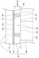
도 2는 도 1의 멤브레인(200)의 상면도이다. 도 2에 도시된 바와 같이, 압력 유닛(100)은 캐리어 헤드(300)의 중심 축선(C)에 대해 적어도 하나의 둘레방향 라인을 따라 적어도 부분적으로 배치된다(도 1 참고). 다시 말하면, 압력 유닛(100)들 중 적어도 2개는 중심 축선(C)에 대해 동일한 둘레방향 라인 상에 위치한다. 이러한 방식으로, 기판(W)의 프로파일 제어는 기판(W)의 중심 축선에 대해 적어도 하나의 둘레방향 라인을 따라 행해질 수 있다(도 1 참고).2 is a top view of the
도 2에 도시된 바와 같이, 일부 실시예에 있어서, 제1 파티션 벽(110)은 중심 축선(C)에 대해 실질적으로 둘레 방향을 따라 연장된다. 다시 말하면, 제1 파티션 벽(110)은 환형의 벽이다. 예를 들면, 제1 파티션 벽(110)은 서로 대향하는 2개의 둘레방향 표면(112)을 갖는다. 둘레방향 표면(112)은 중심 축선(C)에 대해 실질적으로 둘레 방향을 따라 만곡된다. 일부 실시예에 있어서, 제2 파티션 벽(120)은 중심 축선(C)에 대해 실질적으로 반경 방향(R)을 따라 연장된다. 다시 말하면, 제2 파티션 벽(120)은 평판 형상일 수 있다. 예를 들면, 제2 파티션 벽(120)은 제1 파티션 벽(110) 및 하부 벽(130)에 연결되는 적어도 하나의 측방향 표면(122)을 갖는다. 제2 파티션 벽(120)의 측방향 표면(122)은 반경 방향(R)에 대해 실질적으로 평행하다.As shown in Figure 2, in some embodiments, the
도 2에 도시된 바와 같이, 압력 챔버(102)는 2개의 대향하는 제1 파티션 벽(110)들 및 2개의 대향하는 제2 파티션 벽(120)들에 의해 에워싸이게 된다. 제2 파티션 벽(120)들은 간격을 두고 제1 파티션 벽(110)의 둘레방향 표면에 연결된다. 다시 말하면, 중심 축선(C)에 대해 동일한 둘레방향 라인을 따라 이웃하게 배치되는 2개의 압력 챔버(102)는 제2 파티션 벽(120)에 의해 공간적으로 분리되며, 이에 따라 중심 축선(C)에 대해 동일한 둘레방향 라인을 따라 이웃하게 배치되는 압력 챔버(102)들은 서로 유체 연통하지 않을 수 있으므로, 압력 유닛(100)들은 기판(W)의 연마 프로파일에 대한 영역별 제어를 개별적으로 제공할 수 있고(도 1 참고), 이는 기판(W)의 비대칭 형태를 균일하게 하는 것을 용이하게 할 수 있다. 예를 들면, 압력 유닛(100)의 압력 챔버(102)가 개별적으로 가압될 때, 압력 유닛(100)의 하부 벽(130)은 개별적으로 변형될 수 있고, 이에 따라 기판(W)의 다양한 영역을 각각 압박할 수 있어 기판(W)의 비대칭 형태를 균일하게 할 수 있다.As shown in FIG. 2, the
도 2에 도시된 바와 같이, 일부 실시예에 있어서, 동일한 둘레방향 라인 상에 위치하는 압력 유닛(100)은 그 크기 면에서 실질적으로 동일하다. 예를 들면, 동일한 둘레방향 라인 상에 위치하는 압력 유닛(100)은 완전한 원 또는 완전한 링이기보다는 환형 섹터(annular sector)의 형상일 수 있다. 이러한 환형 섹터들은 동일한 면적을 가질 수 있다.As shown in Figure 2, in some embodiments, the
도 2에 도시된 바와 같이, 일부 실시예에 있어서, 압력 유닛(100a)은 환형 압력 유닛이다. 달리 말하면, 압력 유닛(100a)은 링의 형상이다. 일부 실시예에 있어서, 동일한 둘레방향 라인 상에 위치하는 압력 유닛(100)은 환형 압력 유닛(100a)에 의해 둘러싸여 있다. 다시 말하면, 압력 유닛(100)은 환형 압력 유닛(100a)보다 중심 축선(C)에 더 근접하게 위치한다.As shown in Figure 2, in some embodiments, the
도 2에 도시된 바와 같이, 일부 실시예에 있어서, 압력 유닛(100b)은 원형 압력 유닛이다. 달리 말하면, 압력 유닛(100b)은 원의 형상이다. 일부 실시예에 있어서, 압력 유닛(100b)은 실질적으로 중심 축선(C) 상에 위치한다.As shown in Figure 2, in some embodiments, the
도 3은 도 1에서의 캐리어 헤드(300)의 하면도이다. 도 3에 도시된 바와 같이, 일부 실시예에 있어서, 소스(140)는 압력 챔버(102)에 대해 유체를 각각 도입하기 위한 캐리어 헤드(300)의 하부 표면(302) 상에 노출될 수 있으며(도 2 참고), 이에 따라 하부 벽(130)(도 2 참고)은 기판(W)의 부분 영역을 각각 압박할 수 있다(도 1 참고). 따라서, 국지화된 힘이 기판(W)에 인가될 수 있다. 일부 실시예에 있어서, 소스(140)에 의해 도입되는 유체는 가스일 수 있지만, 이로써 한정되는 것은 아니다. 다시 말하면, 소스(140)는 가스 소스일 수 있지만, 이로써 한정되는 것은 아니다.3 is a bottom view of the
도 4는 도 2에서의 라인 B-B'를 따라 취한, 멤브레인(200)의 부분 단면도이다. 도 4에 도시된 바와 같이, 일부 실시예에 있어서, 유체를 도입하기 위한 소스(140)는 각각 압력 챔버(102) 위에 위치하게 되며, 이에 따라 압력 챔버(102)들은 다양한 소스(140)에 의해 개별적으로 가압될 수 있다. 일부 실시예에 있어서, 하부 벽(130)은 유체 수용 표면(132) 및 기판 압박 표면(134)을 가지며, 이들 유체 수용 표면 및 기판 압력 표면은 서로 대향된다. 유체 수용 표면(132)은 소스(140)를 향해 면하고 있다. 소스(140)가 유체 수용 표면(132)을 향해 분출되는 분출 위치는, 제1 파티션 벽(110) 및 제2 파티션 벽(120)으로부터 이격되어 있으며, 이에 따라 소스(140)는 2개 이상의 압력 챔버(102)를 커버(cover)하지 않게 되고, 이는 소스(140)가 압력 챔버(102)들을 개별적으로 가압하는 것을 용이하게 한다.Figure 4 is a partial cross-sectional view of the
도 4에 도시된 바와 같이, 일부 실시예에 있어서, 제1 파티션 벽(110) 및 제2 파티션 벽(120)은 하부 벽(130)의 동일 표면 상에 배치된다. 예를 들면, 제2 파티션 벽(120)의 측방향 표면(122) 및 제1 파티션 벽(110)의 둘레방향 표면(112)은 하부 벽(130)의 유체 수용 표면(132)에 이웃한다. 따라서, 제1 파티션 벽(110)과 하부 벽(130) 사이에는 간격이 없으며, 제2 파티션 벽(120)과 하부 벽(130) 사이에도 또한 간격이 없다. 이에 따라, 압력 챔버(102)의 압력은 다른 압력 챔버(102)의 압력과 무관할 수 있다. 따라서, 하나의 압력 유닛(100)이 기판(W) 상에 가하는 힘은, 다른 압력 유닛(100)이 기판(W) 상에 가하는 힘과 무관하다.As shown in FIG. 4, in some embodiments, the
도 4에 도시된 바와 같이, 일부 실시예에 있어서, 제1 파티션 벽(110) 및 제2 파티션 벽(120)은 캐리어 헤드(300)와 접촉하게 된다. 예를 들면, 제1 파티션 벽(110) 및 제2 파티션 벽(120)은 각각 제1 상부 표면(114) 및 제2 상부 표면(124)을 갖는다. 제1 상부 표면(114) 및 제2 상부 표면(124)은 캐리어 헤드(300)의 하부 표면(302)과 접촉한다. 이러한 구성에 있어서, 제1 파티션 벽(110)과 캐리어 헤드(300) 사이에는 간격이 없으며, 제2 파티션 벽(120)과 캐리어 헤드(300) 사이에도 또한 간격이 없다. 이에 따라, 압력 챔버(102)의 압력은 다른 압력 챔버(102)의 압력과 무관할 수 있다. 따라서, 하나의 압력 유닛(100)이 기판(W) 상에 가하는 힘은, 다른 압력 유닛(100)이 기판(W) 상에 가하는 힘과 무관하다.As shown in FIG. 4, in some embodiments, the
도 4에 도시된 바와 같이, 제1 상부 표면(114) 및 제2 상부 표면(124)은 양자 모두 하부 표면(130)에 대해 원위에 있다. 구체적으로, 제1 상부 표면(114)은 하부 표면(130)의 유체 수용 표면(132)으로부터 이격된, 달리 말하면 하부 표면의 유체 수용 표면과 접촉하지 않는, 제1 파티션 벽(110)의 표면이다. 마찬가지로, 제2 상부 표면(124)은 하부 표면(130)의 유체 수용 표면(132)으로부터 이격된 제2 파티션 벽(120)의 표면이다. 일부 실시예에 있어서, 제1 상부 표면(114)은 제2 상부 표면(124)와 실질적으로 정렬되어, 제1 상부 표면(114) 및 제2 상부 표면(124)이 하부 표면(302)에 접촉되는 것을 가능하게 한다. 달리 말하면, 제1 파티션 벽(110)의 높이(H1)는 제2 파티션 벽(120)의 높이(H2)와 실질적으로 동일할 수 있다. 높이(H1)는 제1 상부 표면(114)과 유체 수용 표면(132) 사이의 거리를 가리키며, 높이(H2)는 제2 상부 표면(124)과 유체 수용 표면(132) 사이의 거리를 가리킨다.As shown in FIG. 4, the first
이제 도 1을 참고한다. 일부 실시예에 있어서, 연마 헤드(10)는 압력 제어기(900)를 포함한다. 압력 제어기(900)는 기판(W) 상에 가해지는 힘을 제어하도록 구성된다. 구체적으로, 압력 제어기(900)는 소스(140)에 의해 도입되는 유체의 압력을 제어한다. 사용자는 기판(W)의 사전 연마 프로파일에 대한 사전 연마 데이터를 획득할 수 있다. 예를 들면, 사전 연마 데이터는 기판을 연마하기에 앞서 기판(W)의 두께 분포를 측정함으로써 획득될 수 있다. 사용자는 사전 연마 데이터에 기초하여 소스(140)에 의해 도입되는 유체의 압력을 제어하기 위해 압력 제어기(900)를 사용할 수 있다. 이러한 구성에 있어서, 압력 챔버(102)는 기판(W)의 사전 연마 프로파일에 의해 결정되는 사전 연마 데이터에 기초하여 가압될 수 있고, 이에 따라 기판(W)의 비대칭 형태를 균일하게 하는 것을 용이하게 한다.Reference is now made to Fig. In some embodiments, the polishing
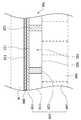
도 5는 본 개시내용의 일부 실시예에 따른 멤브레인(200)의 부분 단면도이다. 도 5에 도시된 바와 같이, 일부 실시예에 있어서, 압력 유닛(100)이 기판(W) 상에 힘을 가할 때 기판(W)에 의한 반력을 탐지하기 위해 적어도 하나의 압전 층(800)이 압력 유닛(100) 상에 배치된다. 압력 제어기(900)(도 1 참고)는 탐지된 반력에 따라 기판(W) 상에 가해지는 힘을 제어할 수 있다.5 is a partial cross-sectional view of a
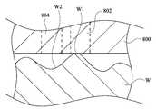
예를 들어, 압전 층(800) 및 기판(W)의 확대 단면도인 도 6을 이제 참고한다. 도 6에 도시된 바와 같이, 기판(W)은 평평하지 않고, 기판은 적어도 하나의 돌출된 부분(W1) 및 적어도 하나의 오목한 부분(W2)을 포함한다. 압전 층(800)이 기판(W)을 향해 이동할 때, 압전 층은 오목한 부분(W2)에 앞서 돌출된 부분(W1)에 닿는다. 압전 층(800)이 기판(W)을 압박하도록 압력 유닛(100)(도 5 참고)에 의해 압전 층(800)에 힘이 가해질 때, 돌출된 부분(W1)을 압박하는 압전 층(800)의 제1 부분(802)은, 오목한 부분(W2)을 압박하는 압전 층(800)의 제2 부분(804)이 견디는 반력보다 더 큰 반력을 견디며, 이에 따라 제1 부분(802) 상에서 압전 재료에 의해 발생되는 전압은 제2 부분(804) 상에서 압전 재료에 의해 발생되는 전압과 동일하지 않다. 이에 따라, 기판(W)의 사전 연마 프로파일에 의해, 특히 비대칭 형태에 의해 전압차가 결정된다. 더욱이, 압력 제어기(900)(도 1 참고)는 압전 층(800)의 전압에 기초하여 소스(140)에 의해 도입되는 유체의 압력을 제어한다(도 1 참고). 이러한 방식으로, 기판(W)에 가해지는 힘은 기판(W)의 사전 연마 프로파일에 의해 결정될 수 있으며, 이에 따라 비대칭 형태를 균일하게 하는 것을 용이하게 한다.6, which is an enlarged cross-sectional view of the
일부 실시예에서는, 도 5에 도시된 바와 같이, CMP 프로세스 동안, 압전 층(800)이 기판(W)에 의한 반력을 계속 탐지할 수 있으며, 압력 제어기(900)(도 1 참고)는 CMP 프로세스 동안 탐지되는 반력에 기초하여 기판(W) 상에 가해지는 힘을 캘리브레이션(calibration)할 수 있다. 이러한 방식으로, 기판(W)에 가해지는 힘은 CMP 프로세스 동안 기판(W)의 순간 프로파일에 의해 결정될 수 있으며, 이에 따라 기판(W)의 비대칭 형태를 균일하게 하는 것을 용이하게 한다.In some embodiments, during the CMP process, the
일부 실시예에서는, 도 5에 도시된 바와 같이, 기판(W)에 의한 반력을 탐지하기 위해, 하부 벽(130)의 기판 압박 표면(134) 상에 압전 층(800)이 배치될 수 있다. 예를 들면, CMP 프로세스 동안, 기판 압박 표면(134) 상에 압전 층(800)이 배치되기 때문에, 압전 층(800)은 하부 벽(130)과 기판(W) 사이에 끼워져 있을 수 있으며, 압전 층은 기판(W)에 의한 반력을 탐지할 수 있다. 다른 실시예에 있어서, 압전 층(800)은 하부 벽(130) 내에 위치하게 될 수 있다. 달리 말하면, 압전 층(800)은 유체 수용 표면(132)과 기판 압박 표면(134) 사이에 끼워져 있을 수 있다.In some embodiments, the
도 7은 본 개시내용의 일부 실시예에 따른 연마 패드(400)의 부분 단면도이다. 도 7에 도시된 바와 같이, 일부 실시예에 있어서, 연마 패드(400)는 베이스부(410), 연결 층(430) 및 커버 층(440)을 포함한다. 압전 층(420)은 연마 패드(400)에 배치된다. 예를 들면, 압전 층(420)은 연마 패드(400)의 베이스부(410) 상에 배치될 수 있다. 연결 층(430)은 베이스부(410)에 대향하여 압전 층(420) 상에 배치될 수 있다. 커버 층(440)은 압전 층(420)에 대향하여 연결 층(430) 상에 배치될 수 있다. 기판(W)(도 1 참고)이 연마 패드(400) 상에 위치하게 되고 연마 헤드(10)에 의해 압박될 때(도 1 참고), 연마 패드(400)는 기판(W)에 힘을 가하며, 반력이 기판(W)에 의해 연마 패드(400) 상에 가해진다. 압전 층(420)은 반력을 탐지할 수 있다. 압력 제어기(900)(도 1 참고)는 압전 층(420)에 의해 탐지된 반력에 따라 기판(W) 상에 가해지는 힘을 제어할 수 있다.7 is a partial cross-sectional view of a
사전 연마된 기판(W)이 평평하지 않을 때, 압전 층(420)의 다양한 부분이 불균일한 힘을 견디게 된다. 이러한 불균일한 힘은 압전 층(420)의 다양한 부분에서 압전 재료가 불균일한 전압을 출력하도록 유도한다. 따라서, 전압차는 기판(W)의 사전 연마 프로파일 또는 CMP 프로세스 중 기판(W)의 순간 프로파일과 같은, 기판(W)의 프로파일에 의해 결정될 수 있다. 더욱이, 압력 제어기(900)(도 1 참고)는 압전 층(420)의 전압에 기초하여 기판(W) 상에 가해지는 힘을 제어할 수 있다. 이러한 방식으로, 기판(W) 상에 가해지는 힘은 압전 층(420)에 의해 획득되는 기판(W)의 프로파일에 의해 결정될 수 있으며, 이에 따라 기판(W)의 비대칭 형태를 균일하게 하는 것을 용이하게 한다. 일부 실시예에 있어서, 압전 층(420)이 채용될 때, 압전 층(800)(도 5 참고)은 생략될 수 있다. 반대로, 일부 실시예에 있어서, 압전 층(800)이 채용될 때, 압전 층(420)은 생략될 수 있다. 일부 실시예에 있어서, 압전 층(420) 및 압전 층(800)이 채용될 수 있다.When the pre-polished substrate W is not planar, various portions of the
도 7에 도시된 바와 같이, 일부 실시예에 있어서, 베이스부(410)의 재료는 폴리머일 수 있지만, 이로써 한정되는 것은 아니다. 일부 실시예에 있어서, 접속 층(430)의 재료는 접착제(glue)일 수 있지만, 이로써 한정되는 것은 아니다. 일부 실시예에 있어서, 상부 층(440)의 재료는 폴리머일 수 있지만, 이로써 한정되는 것은 아니다.As shown in FIG. 7, in some embodiments, the material of the
도 8은 본 개시내용의 일부 실시예에 따른 멤브레인(200a)의 상면도이다. 도 8에 도시된 바와 같이, 이 실시예와 도 2에 도시된 실시예 사이의 주요한 차이는, 압력 유닛(100)이 환형 압력 유닛(100a)에 의해 둘러싸이지 않는다는 것이다(도 2 참고). 구체적으로, 환형 압력 유닛(100a)이 채용되지 않는다.8 is a top view of a
도 9는 본 개시내용의 일부 실시예에 따른 멤브레인(200b)의 상면도이다. 도 9에 도시된 바와 같이, 이 실시예와 도 2에 도시된 실시예 사이의 주요한 차이는, 압력 유닛(100)들 중 적어도 2개가 중심 축선(C) 상에 배치된다는 것, 그리고 원형 압력 유닛(100b)이 채용되지 않는다는 것이다(도 2 참고).Figure 9 is a top view of a
도 10은 본 개시내용의 일부 실시예에 따른 멤브레인(200c)의 상면도이다. 도 10에 도시된 바와 같이, 일부 실시예에 있어서, 제2 파티션 벽(120c)들 중 적어도 하나는 아치 형상이다. 예를 들면, 제2 파티션 벽(120c)의 측방향 표면(122c)은 만곡된 표면이다. 이에 따라, 압력 유닛(100)의 경계는 만곡된다.10 is a top view of a
일부 실시예에 있어서, 캐리어 헤드 및 이 캐리어 헤드 상에 배치되는 복수 개의 압력 유닛을 포함하는 연마 헤드가 개시된다. 압력 유닛들 중 적어도 2개는 캐리어 헤드의 중심 축선에 대해 동일한 둘레방향 라인 상에 위치하게 된다.In some embodiments, a polishing head is disclosed that includes a carrier head and a plurality of pressure units disposed on the carrier head. At least two of the pressure units are located on the same circumferential line with respect to the central axis of the carrier head.
또한, 연마 헤드, 플레튼 및 슬러리 도입 메커니즘을 포함하는 화학 기계적 연마 시스템이 개시된다. 연마 헤드는 캐리어 헤드 및 이 캐리어 헤드 상에 배치되는 복수 개의 압력 유닛을 포함한다. 압력 유닛은 캐리어 헤드의 중심 축선에 대해 적어도 하나의 둘레방향 라인을 따라 적어도 부분적으로 배치된다. 플레튼은 연마 헤드 아래에 배치된다. 슬러리 도입 메커니즘은 플레튼 위에 배치된다.Also disclosed is a chemical mechanical polishing system comprising a polishing head, a platen and a slurry introduction mechanism. The polishing head includes a carrier head and a plurality of pressure units disposed on the carrier head. The pressure unit is disposed at least partially along at least one circumferential line with respect to the central axis of the carrier head. The platen is placed under the polishing head. The slurry introduction mechanism is placed on the platen.
또한, 기판을 연마하는 방법이 개시된다. 상기 방법은 아래의 단계들을 포함한다. 슬러리가 연마 패드 상에 공급된다. 기판이 연마 패드에 대해 유지된다. 기판의 중심 축선에 대해 동일한 둘레방향 라인 상에 위치하게 되는 적어도 2개의 압력 유닛은 개별적으로 작동된다. 연마 패드 및 기판 양자 모두는 회전하게 된다.Also disclosed is a method of polishing a substrate. The method includes the following steps. A slurry is fed onto the polishing pad. The substrate is held against the polishing pad. At least two pressure units which are located on the same circumferential line with respect to the central axis of the substrate are operated individually. Both the polishing pad and the substrate are rotated.
본 명세서에서 사용되는 용어는 일반적으로 당업계 및 각각의 용어가 사용되는 특정한 상황에서 그 통상의 의미를 갖는다. 본 명세서에서 언급되는 임의의 용어의 예를 비롯하여, 본 명세서에서의 사용례는 단지 설명을 위한 것이며, 어떠한 방식으로도 임의의 예시된 용어 또는 개시내용의 범위 및 의미를 한정하지 않는다. 마찬가지로, 본 개시내용은 본 명세서에 제시된 다양한 실시예로 한정되지 않는다.The terms used herein generally have their ordinary meaning in the art and in the specific context in which each term is used. The use examples in this specification, including examples of any of the terms mentioned herein, are for the purpose of illustration only and are not intended to limit the scope and meaning of any illustrated terms or disclosure content in any way. Likewise, the present disclosure is not limited to the various embodiments presented herein.
용어 "제1", "제2" 등이 본 명세서에서 다양한 요소를 설명하기 위해 사용될 수 있지만, 이들 요소는 이러한 용어에 의해 한정되지 않는다는 것을 이해할 것이다. 이들 용어는 하나의 요소를 다른 요소와 구분하기 위해 사용된다. 예를 들면, 실시예의 범위로부터 벗어나지 않으면서, 제1 요소는 제2 요소라 불릴 수도 있고, 마찬가지로 제2 요소는 제1 요소라 불릴 수도 있다. 본 명세서에서 사용될 때, 용어 "및/또는"은 관련되어 나열된 물품들 중 임의의 물품 및 이들 물품 중 하나 이상의 모든 조합을 포함한다.Although the terms "first "," second "and the like may be used herein to describe various elements, it will be understood that these elements are not limited by these terms. These terms are used to distinguish one element from another. For example, without departing from the scope of the embodiment, the first element may be referred to as the second element, and likewise the second element may be referred to as the first element. As used herein, the terms "and / or" include any of the articles listed and all combinations of one or more of these articles.
본 명세서에서 사용될 때, 용어 "포함하는", "비롯하여", "구비하는", "수용하는", "관련되는" 등은 제약을 두지 않는다는 것을 이해할 것이며, 즉 포함하는 것을 의미하지만 이로써 한정되지는 않는다.As used herein, the terms "comprises," "including," "comprising," "accommodating," "relating," and the like, Do not.
전체 개시내용에서 용어 "실질적으로"는 기술적인 특징의 정수에 영향을 주지 않는 임의의 사소한 변경 또는 변형을 포함하는 실시예가 본 개시내용의 범위에 포함될 수 있다는 것을 의미한다. 전체 개시내용에서 구문 "특징 A가 특징 B 상에 배치된다"는, 특징 A가 특징 B 위에 직접 또는 간접적으로 위치하게 된다는 것을 가리킨다. 다시 말하면, 특징 B의 평면에 대해 투영된 특징 A의 투영은 특징 B를 덮는다. 따라서, 특징 A는 특징 B 상에 오직 직접적으로만 쌓여이지 않을 수 있고, 특징 A가 특징 B 위에 여전히 위치하고 있는 한 추가적인 특징 C가 특징 A와 특징 B 사이에 게재되어 있을 수 있다.The term "substantially" in the context of the entire disclosure is intended to encompass within the scope of the present disclosure any embodiment that includes any minor variations or modifications that do not affect the essence of the technical features. In the entire disclosure, the phrase "Feature A is placed on Feature B" indicates that Feature A is located directly or indirectly on Feature B. In other words, the projection of the projected feature A over the plane of feature B covers feature B. Thus, feature A may not only be directly superimposed on feature B, and an additional feature C may be placed between feature A and feature B as long as feature A is still located on feature B. [
명세서 전반에 걸쳐 "일부 실시예"라 함은, 실시예와 관련하여 설명된 구체적인 특징, 구조, 구현물 또는 특성이 본 개시내용의 적어도 하나의 실시예에 포함된다는 것을 의미한다. 따라서, 명세서 전반에 걸쳐 여러 위치에서 "일부 실시예에 있어서"라는 문구를 사용하는 것은, 반드시 모두 동일한 실시예를 가리키는 것은 아니다. 더욱이, 구체적인 특징, 구조, 구현물 또는 특성이 하나 이상의 실시예에서 임의의 적절한 방식으로 조합될 수 있다.Throughout the specification, "some embodiments" means that a particular feature, structure, implementation, or characteristic described in connection with the embodiment is included in at least one embodiment of the present disclosure. Accordingly, the use of the phrase "in some embodiments" in various places throughout the specification is not necessarily all referring to the same embodiment. Furthermore, a particular feature, structure, implementation, or characteristic may be combined in any suitable manner in one or more embodiments.
당업자가 이해하는 바와 같이, 본 개시내용의 이상의 실시예는 본 개시내용을 한정하려는 것이 아니라 본 개시내용을 설명하려는 것이다. 이는 첨부된 청구범위의 사상 및 범위 내에 포함되는 다양한 변경 및 유사한 구성을 포괄하려는 의도이며, 첨부된 청구범위의 범위는 이러한 모든 변형 및 유사한 구성을 포괄하도록 가장 광의로 해석되어야 한다.As those skilled in the art will appreciate, the foregoing embodiments of the present disclosure are not intended to limit the present disclosure but to illustrate the present disclosure. It is intended to cover various modifications and similar arrangements included within the spirit and scope of the appended claims, the scope of the appended claims should be accorded the broadest interpretation so as to encompass all such modifications and similar structures.
10 : 연마 헤드100 : 압력 유닛
200 : 멤브레인300 : 캐리어 헤드
400 : 연마 패드500 : 슬러리 도입 메커니즘
600 : 플래튼800 : 압전 층
900 : 압력 제어기10: polishing head 100: pressure unit
200: Membrane 300: Carrier head
400: polishing pad 500: slurry introduction mechanism
600: Platen 800: Piezoelectric layer
900: Pressure controller
Claims (9)
Translated fromKorean캐리어 헤드;
상기 캐리어 헤드 상에 배치되는 복수 개의 압력 유닛들로서, 압력 유닛들 중 적어도 2개는 상기 캐리어 헤드의 중심 축선에 대해 동일한 둘레방향 라인 상에 위치하게 되는 것인 복수 개의 압력 유닛들;
상기 압력 유닛들이 기판 상에 힘을 가할 때 상기 기판에 의한 반력을 탐지하기 위해 상기 압력 유닛들 상에 배치되는 적어도 하나의 압전 층; 및
탐지된 반력에 따라 상기 기판 상에 가해지는 힘을 제어하기 위한 압력 제어기
를 포함하고,
상기 압력 유닛들 중 적어도 일부의 각각은 가요성 하부 벽 및 상기 가요성 하부 벽으로부터 상기 캐리어 헤드를 향하여 돌출하는 복수의 파티션 벽들을 포함하는 것인, 연마 헤드.A polishing head for a chemical mechanical polishing system,
Carrier head;
A plurality of pressure units disposed on the carrier head, wherein at least two of the pressure units are positioned on the same circumferential line with respect to the central axis of the carrier head;
At least one piezoelectric layer disposed on the pressure units to detect a reaction force by the substrate when the pressure units exert a force on the substrate; And
A pressure controller for controlling a force applied to the substrate in accordance with the detected reaction force;
Lt; / RTI >
Wherein each of at least some of the pressure units comprises a flexible bottom wall and a plurality of partition walls projecting from the flexible bottom wall toward the carrier head.
하부 벽;
상기 캐리어 헤드에 상기 하부 벽을 연결하는 적어도 2개의 대향하는 제1 파티션 벽들;
상기 하부 벽을 상기 캐리어 헤드에 연결하는 적어도 2개의 대향하는 제2 파티션 벽들로서, 상기 하부 벽, 상기 제1 파티션 벽들, 상기 제2 파티션 벽들 및 상기 캐리어 헤드가 압력 챔버를 형성하도록 하는 것인 제2 파티션 벽들; 및
압력 챔버 내로 유체를 도입하기 위한 소스
를 포함하는 것인, 연마 헤드.2. The apparatus of claim 1, wherein at least one of the pressure units comprises:
Bottom wall;
At least two opposing first partition walls connecting the lower wall to the carrier head;
At least two opposing second partition walls connecting the lower wall to the carrier head such that the lower wall, the first partition walls, the second partition walls and the carrier head form a pressure chamber 2 partition walls; And
A source for introducing fluid into the pressure chamber
The polishing head comprising:
연마 헤드로서,
캐리어 헤드; 및
상기 캐리어 헤드 상에 배치되는 유체적으로 격리된 복수 개의 압력 유닛들로서, 상기 압력 유닛들 중 적어도 일부의 각각은 가요성 하부 벽 및 상기 가요성 하부 벽으로부터 상기 캐리어 헤드를 향하여 연장하는 복수의 파티션 벽들을 포함하고, 상기 압력 유닛들의 가요성 하부 벽들은 서로 유체적으로 격리되고, 상기 캐리어 헤드의 중심 축선에 대한 둘레방향 라인은 상기 유체적으로 격리된 압력 유닛들 중 적어도 두 개의 압력 유닛들의 가요성 하부 벽을 통과하는 것인, 복수 개의 압력 유닛들
을 포함하는 연마 헤드;
상기 연마 헤드 아래에 배치되는 플레튼(platen); 및
상기 플레튼 위에 배치되는 슬러리 도입 메커니즘
을 포함하는 것인, 화학 기계적 연마 시스템.As a chemical mechanical polishing system,
As a polishing head,
Carrier head; And
A plurality of pressure units disposed on the carrier head, each of at least some of the pressure units comprising a flexible lower wall and a plurality of partition walls extending from the flexible lower wall toward the carrier head, Wherein the flexible lower walls of the pressure units are fluidly isolated from one another and a circumferential line with respect to the central axis of the carrier head defines a flexibility of at least two of the fluidically isolated pressure units A plurality of pressure units < RTI ID = 0.0 >
A polishing head;
A platen disposed below the polishing head; And
The slurry introduction mechanism disposed on the platen
Wherein the chemical mechanical polishing system comprises:
상기 플레튼 상에 배치되는 적어도 하나의 연마 패드;
상기 연마 패드가 기판 상에 힘을 가할 때 상기 기판에 의한 반력을 탐지하기 위해 상기 연마 패드 상에 배치되는 적어도 하나의 압전 층; 및
탐지된 반력에 따라 상기 기판 상에 가해지는 힘을 제어하기 위한 압력 제어기
를 더 포함하는 것인, 화학 기계적 연마 시스템.6. The method of claim 5,
At least one polishing pad disposed on the platen;
At least one piezoelectric layer disposed on the polishing pad to detect a reaction force by the substrate when the polishing pad applies a force on the substrate; And
A pressure controller for controlling a force applied to the substrate in accordance with the detected reaction force;
Further comprising a chemical mechanical polishing system.
연마 패드 상에 슬러리를 공급하는 단계;
상기 연마 패드에 대해 기판을 유지하는 단계;
상기 기판의 중심 축선에 대해 동일한 둘레방향 라인 상에 위치하게 되는 적어도 2개의 압력 유닛들을 개별적으로 작동시키는 단계 - 상기 적어도 2개의 압력 유닛들 각각은 가요성 하부 벽 및 상기 가요성 하부 벽으로부터 돌출하는 복수의 파티션 벽들을 포함함 - ;
상기 연마 패드 및 상기 기판 양자 모두를 회전시키는 단계;
상기 적어도 2개의 압력 유닛들이 상기 기판 상에 힘을 가할 때 상기 기판에 의한 반력을 탐지하는 단계로서, 상기 반력을 탐지하는 단계는 상기 적어도 2개의 압력 유닛들 상에 배치되는 적어도 하나의 압전 층에 의해 수행되는 것인, 반력을 탐지하는 단계; 및
탐지된 반력에 따라 상기 기판 상에 가해지는 힘을 제어하는 단계
를 포함하는, 기판 연마 방법.A method of polishing a substrate,
Feeding the slurry onto a polishing pad;
Maintaining a substrate relative to the polishing pad;
Separately actuating at least two pressure units located on the same circumferential line with respect to a central axis of the substrate, each of the at least two pressure units having a flexible lower wall and a plurality of pressure- A plurality of partition walls;
Rotating both the polishing pad and the substrate;
Detecting a reaction force by the substrate when the at least two pressure units exert a force on the substrate, wherein the step of detecting the reaction force comprises the steps of: detecting at least one piezoelectric layer disposed on the at least two pressure units Detecting a reaction force; And
Controlling the force applied on the substrate in accordance with the detected reaction force
And polishing the substrate.
사전 연마 데이터를 획득하는 단계
를 더 포함하며,
상기 압력 유닛들을 개별적으로 작동시키는 단계는 상기 사전 연마 데이터에 따라 상기 압력 유닛들을 개별적으로 작동시키는 것을 포함하는 것인, 기판 연마 방법.8. The method of claim 7,
Obtaining the pre-polishing data
Further comprising:
Wherein actuating the pressure units individually comprises actuating the pressure units individually in accordance with the pre-polishing data.
캐리어 헤드; 및
상기 캐리어 헤드 상에 배치되는 유체적으로 격리된 복수 개의 압력 유닛들로서, 상기 압력 유닛들 중 적어도 두 개는 상기 캐리어 헤드의 중심 축선에 대해 동일한 둘레방향 라인을 오버랩하는 것인, 복수 개의 압력 유닛들
을 포함하고,
상기 압력 유닛들 중 적어도 일부의 각각은 가요성 하부 벽 및 상기 가요성 하부 벽으로부터 상기 캐리어 헤드를 향하여 돌출하는 복수의 파티션 벽들을 포함하고,
상기 압력 유닛들의 가요성 하부 벽들은 서로 유체적으로 격리되고 상기 캐리어 헤드의 중심 축선에 대해 동일한 둘레방향 라인을 오버랩하는 것인, 연마 헤드.
A polishing head for a chemical mechanical polishing system,
Carrier head; And
Wherein a plurality of pressure units are disposed on the carrier head and wherein at least two of the pressure units overlap the same circumferential line with respect to the central axis of the carrier head,
/ RTI >
Wherein each of at least some of the pressure units comprises a flexible lower wall and a plurality of partition walls projecting from the flexible lower wall toward the carrier head,
Wherein the flexible lower walls of the pressure units are fluidly isolated from each other and overlap the same circumferential line with respect to the central axis of the carrier head.
Applications Claiming Priority (2)
| Application Number | Priority Date | Filing Date | Title |
|---|---|---|---|
| US14/103,629 | 2013-12-11 | ||
| US14/103,629US10328549B2 (en) | 2013-12-11 | 2013-12-11 | Polishing head, chemical-mechanical polishing system and method for polishing substrate |
Related Parent Applications (1)
| Application Number | Title | Priority Date | Filing Date |
|---|---|---|---|
| KR1020140178337ADivisionKR20150068331A (en) | 2013-12-11 | 2014-12-11 | Polishing head, chemical-mechanical polishing system and method for polishing substrate |
Publications (2)
| Publication Number | Publication Date |
|---|---|
| KR20160027959A KR20160027959A (en) | 2016-03-10 |
| KR101719097B1true KR101719097B1 (en) | 2017-04-04 |
Family
ID=53270217
Family Applications (2)
| Application Number | Title | Priority Date | Filing Date |
|---|---|---|---|
| KR1020140178337ACeasedKR20150068331A (en) | 2013-12-11 | 2014-12-11 | Polishing head, chemical-mechanical polishing system and method for polishing substrate |
| KR1020160019176AActiveKR101719097B1 (en) | 2013-12-11 | 2016-02-18 | Polishing head, chemical-mechanical polishing system and method for polishing substrate |
Family Applications Before (1)
| Application Number | Title | Priority Date | Filing Date |
|---|---|---|---|
| KR1020140178337ACeasedKR20150068331A (en) | 2013-12-11 | 2014-12-11 | Polishing head, chemical-mechanical polishing system and method for polishing substrate |
Country Status (3)
| Country | Link |
|---|---|
| US (3) | US10328549B2 (en) |
| KR (2) | KR20150068331A (en) |
| CN (2) | CN104708529A (en) |
Families Citing this family (13)
| Publication number | Priority date | Publication date | Assignee | Title |
|---|---|---|---|---|
| US10328549B2 (en) | 2013-12-11 | 2019-06-25 | Taiwan Semiconductor Manufacturing Co., Ltd. | Polishing head, chemical-mechanical polishing system and method for polishing substrate |
| US10315286B2 (en)* | 2016-06-14 | 2019-06-11 | Axus Technologi, Llc | Chemical mechanical planarization carrier system |
| CN109202923A (en)* | 2017-07-03 | 2019-01-15 | 株式会社安川电机 | Robot grinding system, robot system, grinding device, Acetabula device, driving part and Pressure generator |
| KR102512133B1 (en)* | 2018-05-10 | 2023-03-22 | 주식회사 케이씨텍 | Wafer carrier and control method thereof |
| CN109648460A (en)* | 2018-12-20 | 2019-04-19 | 丰豹智能科技(上海)有限公司 | A kind of detachable sensing device of no current multi partition |
| US11731231B2 (en) | 2019-01-28 | 2023-08-22 | Micron Technology, Inc. | Polishing system, polishing pad, and related methods |
| CN211728760U (en)* | 2019-12-31 | 2020-10-23 | 深圳市中光工业技术研究院 | A wafer polishing device |
| US11602821B2 (en)* | 2020-01-17 | 2023-03-14 | Taiwan Semiconductor Manufacturing Company Ltd. | Wafer polishing head, system thereof, and method using the same |
| KR102368924B1 (en) | 2020-02-28 | 2022-03-03 | 김진호 | Apparatus for tightening wire |
| KR102733621B1 (en)* | 2020-06-24 | 2024-11-25 | 어플라이드 머티어리얼스, 인코포레이티드 | Polishing carrier head with piezoelectric pressure control |
| CN115723036B (en)* | 2022-09-20 | 2025-03-28 | 广东粤港澳大湾区黄埔材料研究院 | A pressure distribution detection system and method for polishing equipment |
| CN119036298A (en)* | 2024-10-14 | 2024-11-29 | 华海清科股份有限公司 | Polishing head pressure detection apparatus, polishing head pressure detection method, and polishing apparatus for wafer processing |
| CN119427174A (en)* | 2024-11-07 | 2025-02-14 | 西安奕斯伟材料科技股份有限公司 | Polishing method, polishing equipment and silicon wafer |
Citations (1)
| Publication number | Priority date | Publication date | Assignee | Title |
|---|---|---|---|---|
| JP2002079454A (en)* | 2000-09-06 | 2002-03-19 | Canon Inc | Board holding device, and board polishing method and device using the same |
Family Cites Families (35)
| Publication number | Priority date | Publication date | Assignee | Title |
|---|---|---|---|---|
| DE3430499C2 (en)* | 1984-08-18 | 1986-08-14 | Fa. Carl Zeiss, 7920 Heidenheim | Method and device for lapping or polishing optical workpieces |
| JP2861883B2 (en)* | 1995-09-18 | 1999-02-24 | 日本電気株式会社 | Wafer polishing method and apparatus |
| US5720845A (en)* | 1996-01-17 | 1998-02-24 | Liu; Keh-Shium | Wafer polisher head used for chemical-mechanical polishing and endpoint detection |
| KR100218309B1 (en) | 1996-07-09 | 1999-09-01 | 구본준 | Semiconductor wafer leveling detection device and method of CMP device |
| US5868896A (en)* | 1996-11-06 | 1999-02-09 | Micron Technology, Inc. | Chemical-mechanical planarization machine and method for uniformly planarizing semiconductor wafers |
| DE19651761A1 (en)* | 1996-12-12 | 1998-06-18 | Wacker Siltronic Halbleitermat | Method and device for polishing semiconductor wafers |
| US6531397B1 (en)* | 1998-01-09 | 2003-03-11 | Lsi Logic Corporation | Method and apparatus for using across wafer back pressure differentials to influence the performance of chemical mechanical polishing |
| US6394882B1 (en)* | 1999-07-08 | 2002-05-28 | Vanguard International Semiconductor Corporation | CMP method and substrate carrier head for polishing with improved uniformity |
| US6558232B1 (en)* | 2000-05-12 | 2003-05-06 | Multi-Planar Technologies, Inc. | System and method for CMP having multi-pressure zone loading for improved edge and annular zone material removal control |
| CN1852787A (en)* | 2000-08-31 | 2006-10-25 | 多平面技术公司 | Chemical mechanical polishing (CMP) head, apparatus and method, and planarized semiconductor wafer produced thereby |
| US6675058B1 (en)* | 2001-03-29 | 2004-01-06 | Advanced Micro Devices, Inc. | Method and apparatus for controlling the flow of wafers through a process flow |
| US6863771B2 (en)* | 2001-07-25 | 2005-03-08 | Micron Technology, Inc. | Differential pressure application apparatus for use in polishing layers of semiconductor device structures and methods |
| JP4107835B2 (en) | 2001-12-06 | 2008-06-25 | 株式会社荏原製作所 | Substrate holding device and polishing device |
| US7008299B2 (en)* | 2002-08-29 | 2006-03-07 | Micron Technology, Inc. | Apparatus and method for mechanical and/or chemical-mechanical planarization of micro-device workpieces |
| US7131891B2 (en)* | 2003-04-28 | 2006-11-07 | Micron Technology, Inc. | Systems and methods for mechanical and/or chemical-mechanical polishing of microfeature workpieces |
| US7052371B2 (en)* | 2003-05-29 | 2006-05-30 | Tbw Industries Inc. | Vacuum-assisted pad conditioning system and method utilizing an apertured conditioning disk |
| JP2005011977A (en) | 2003-06-18 | 2005-01-13 | Ebara Corp | Device and method for substrate polishing |
| KR20050008231A (en)* | 2003-07-14 | 2005-01-21 | 삼성전자주식회사 | Head pressure adjustment apparatus of chemical mechanical polishing apparatus and the head pressure adjustment method there of |
| EP1692457A4 (en)* | 2003-12-11 | 2007-09-26 | Proteus Biomedical Inc | Implantable pressure sensors |
| KR100586018B1 (en)* | 2004-02-09 | 2006-06-01 | 삼성전자주식회사 | Flexible membrane for polishing head and polishing device comprising same |
| US7150673B2 (en)* | 2004-07-09 | 2006-12-19 | Ebara Corporation | Method for estimating polishing profile or polishing amount, polishing method and polishing apparatus |
| WO2007018391A1 (en)* | 2005-08-05 | 2007-02-15 | Seung-Hun Bae | Chemical mechanical polishing apparatus |
| US20070149094A1 (en)* | 2005-12-28 | 2007-06-28 | Choi Jae Y | Monitoring Device of Chemical Mechanical Polishing Apparatus |
| US20070167110A1 (en)* | 2006-01-16 | 2007-07-19 | Yu-Hsiang Tseng | Multi-zone carrier head for chemical mechanical polishing and cmp method thereof |
| CN101007396A (en)* | 2006-01-24 | 2007-08-01 | 联华电子股份有限公司 | Polishing head applied to chemical mechanical polishing process and chemical mechanical polishing method |
| US8129279B2 (en) | 2008-10-13 | 2012-03-06 | Taiwan Semiconductor Manufacturing Co., Ltd. | Chemical mechanical polish process control for improvement in within-wafer thickness uniformity |
| CN102294646A (en)* | 2010-06-23 | 2011-12-28 | 中芯国际集成电路制造(上海)有限公司 | Grinding head and chemical mechanical grinding machine |
| CN102501187A (en)* | 2011-11-04 | 2012-06-20 | 厦门大学 | Polishing disk capable of adjusting regional pressure |
| CN103302587B (en)* | 2012-03-16 | 2016-01-06 | 中芯国际集成电路制造(上海)有限公司 | Chemical mechanical polishing device and system |
| US9067295B2 (en)* | 2012-07-25 | 2015-06-30 | Applied Materials, Inc. | Monitoring retaining ring thickness and pressure control |
| US8962224B2 (en) | 2012-08-13 | 2015-02-24 | Applied Materials, Inc. | Methods for controlling defects for extreme ultraviolet lithography (EUVL) photomask substrate |
| US9233452B2 (en)* | 2012-10-29 | 2016-01-12 | Wayne O. Duescher | Vacuum-grooved membrane abrasive polishing wafer workholder |
| US10328549B2 (en)* | 2013-12-11 | 2019-06-25 | Taiwan Semiconductor Manufacturing Co., Ltd. | Polishing head, chemical-mechanical polishing system and method for polishing substrate |
| KR102447219B1 (en) | 2015-10-01 | 2022-09-23 | 인테벡, 인코포레이티드 | Wafer plate and mask arrangement for substrate fabrication |
| SG11201906154PA (en) | 2017-01-17 | 2019-08-27 | Hoya Corp | Substrate with conductive film, substrate with multilayer reflective film, reflective mask blank, reflective mask and method for manufacturing semiconductor device |
- 2013
- 2013-12-11USUS14/103,629patent/US10328549B2/enactiveActive
- 2014
- 2014-12-10CNCN201410756619.5Apatent/CN104708529A/enactivePending
- 2014-12-10CNCN202010782692.5Apatent/CN111941269B/enactiveActive
- 2014-12-11KRKR1020140178337Apatent/KR20150068331A/ennot_activeCeased
- 2016
- 2016-02-18KRKR1020160019176Apatent/KR101719097B1/enactiveActive
- 2019
- 2019-06-24USUS16/449,855patent/US11407083B2/enactiveActive
- 2022
- 2022-07-22USUS17/871,259patent/US12128522B2/enactiveActive
Patent Citations (1)
| Publication number | Priority date | Publication date | Assignee | Title |
|---|---|---|---|---|
| JP2002079454A (en)* | 2000-09-06 | 2002-03-19 | Canon Inc | Board holding device, and board polishing method and device using the same |
Also Published As
| Publication number | Publication date |
|---|---|
| CN104708529A (en) | 2015-06-17 |
| CN111941269B (en) | 2022-07-22 |
| US10328549B2 (en) | 2019-06-25 |
| US20220355437A1 (en) | 2022-11-10 |
| US20150158140A1 (en) | 2015-06-11 |
| US12128522B2 (en) | 2024-10-29 |
| US20190308295A1 (en) | 2019-10-10 |
| US11407083B2 (en) | 2022-08-09 |
| KR20160027959A (en) | 2016-03-10 |
| CN111941269A (en) | 2020-11-17 |
| KR20150068331A (en) | 2015-06-19 |
Similar Documents
| Publication | Publication Date | Title |
|---|---|---|
| KR101719097B1 (en) | Polishing head, chemical-mechanical polishing system and method for polishing substrate | |
| JP6867430B2 (en) | Single-sided polishing head with flexible center, with recesses and caps | |
| TW548162B (en) | System and method for CMP head having multi-pressure zone loading for improved edge and annular zone material removal control | |
| TW553799B (en) | System and method for pneumatic diaphragm cmp head having separate retaining ring and multi-region wafer pressure control | |
| US7014535B2 (en) | Carrier head having low-friction coating and planarizing machine using same | |
| TWI375294B (en) | Elastic membrane | |
| US7335088B1 (en) | CMP system with temperature-controlled polishing head | |
| KR20130083873A (en) | Retaining ring, flexible membrane for applying load to a retaining ring, and retaining ring assembly | |
| US10118273B2 (en) | Polishing head, CMP apparatus having polishing head, and semiconductor integrated circuit manufacturing method using CMP apparatus | |
| US20110230123A1 (en) | Polisher, pressure plate of the polisher and method of polishing | |
| KR101589445B1 (en) | Carrier head of chemical mechanical apparatus and membrane used therein | |
| KR20140125289A (en) | Carrier head of chemical mechanical apparatus and membrane used therein | |
| TW200425995A (en) | Substrate holding apparatus and polishing apparatus | |
| CN108818294A (en) | grinding head, grinding system and grinding method | |
| TW200940251A (en) | Flexible membrane assembly for a CMP system | |
| JPH09225821A5 (en) | ||
| TW202231405A (en) | System and method for chemical mechanical polishing | |
| KR101653536B1 (en) | Chemical mechanical polishing apparatus | |
| KR102181101B1 (en) | Carrier head of chemical mechanical apparatus | |
| TW201902623A (en) | Elastic film used for polishing head that comprises a film body and an anti-sticking layer and capable of reducing the risk of machine breakdown during the manufacturing process | |
| KR101411836B1 (en) | Membrane of carrier head in chemical mechanical polishing apparatus and carrier head using same | |
| KR102437235B1 (en) | Apparatus of polishing wafer | |
| CN115135449A (en) | Deformable substrate chuck | |
| TW201538273A (en) | Manufacturing method and equipment of polishing pad | |
| KR101583432B1 (en) | Membrane for using cmp head |
Legal Events
| Date | Code | Title | Description |
|---|---|---|---|
| A107 | Divisional application of patent | ||
| A201 | Request for examination | ||
| PA0107 | Divisional application | Comment text:Divisional Application of Patent Patent event date:20160218 Patent event code:PA01071R01D Filing date:20141211 Application number text:1020140178337 | |
| PA0201 | Request for examination | ||
| PG1501 | Laying open of application | ||
| E902 | Notification of reason for refusal | ||
| PE0902 | Notice of grounds for rejection | Comment text:Notification of reason for refusal Patent event date:20160405 Patent event code:PE09021S01D | |
| AMND | Amendment | ||
| E601 | Decision to refuse application | ||
| PE0601 | Decision on rejection of patent | Patent event date:20161104 Comment text:Decision to Refuse Application Patent event code:PE06012S01D Patent event date:20160405 Comment text:Notification of reason for refusal Patent event code:PE06011S01I | |
| AMND | Amendment | ||
| PX0901 | Re-examination | Patent event code:PX09011S01I Patent event date:20161104 Comment text:Decision to Refuse Application Patent event code:PX09012R01I Patent event date:20160705 Comment text:Amendment to Specification, etc. | |
| PX0701 | Decision of registration after re-examination | Patent event date:20161220 Comment text:Decision to Grant Registration Patent event code:PX07013S01D Patent event date:20161207 Comment text:Amendment to Specification, etc. Patent event code:PX07012R01I Patent event date:20161104 Comment text:Decision to Refuse Application Patent event code:PX07011S01I Patent event date:20160705 Comment text:Amendment to Specification, etc. Patent event code:PX07012R01I | |
| X701 | Decision to grant (after re-examination) | ||
| GRNT | Written decision to grant | ||
| PR0701 | Registration of establishment | Comment text:Registration of Establishment Patent event date:20170316 Patent event code:PR07011E01D | |
| PR1002 | Payment of registration fee | Payment date:20170316 End annual number:3 Start annual number:1 | |
| PG1601 | Publication of registration | ||
| PR1001 | Payment of annual fee | Payment date:20220303 Start annual number:6 End annual number:6 | |
| PR1001 | Payment of annual fee | Payment date:20240305 Start annual number:8 End annual number:8 | |
| PR1001 | Payment of annual fee | Payment date:20250305 Start annual number:9 End annual number:9 |