KR101717890B1 - Imaging system and imaging device - Google Patents
Imaging system and imaging deviceDownload PDFInfo
- Publication number
- KR101717890B1 KR101717890B1KR1020167003897AKR20167003897AKR101717890B1KR 101717890 B1KR101717890 B1KR 101717890B1KR 1020167003897 AKR1020167003897 AKR 1020167003897AKR 20167003897 AKR20167003897 AKR 20167003897AKR 101717890 B1KR101717890 B1KR 101717890B1
- Authority
- KR
- South Korea
- Prior art keywords
- imaging
- image
- image data
- image pickup
- time
- Prior art date
- Legal status (The legal status is an assumption and is not a legal conclusion. Google has not performed a legal analysis and makes no representation as to the accuracy of the status listed.)
- Expired - Fee Related
Links
Images


Classifications
- H04N5/232—
- H—ELECTRICITY
- H04—ELECTRIC COMMUNICATION TECHNIQUE
- H04N—PICTORIAL COMMUNICATION, e.g. TELEVISION
- H04N7/00—Television systems
- H04N7/18—Closed-circuit television [CCTV] systems, i.e. systems in which the video signal is not broadcast
- H04N7/183—Closed-circuit television [CCTV] systems, i.e. systems in which the video signal is not broadcast for receiving images from a single remote source
- F—MECHANICAL ENGINEERING; LIGHTING; HEATING; WEAPONS; BLASTING
- F25—REFRIGERATION OR COOLING; COMBINED HEATING AND REFRIGERATION SYSTEMS; HEAT PUMP SYSTEMS; MANUFACTURE OR STORAGE OF ICE; LIQUEFACTION SOLIDIFICATION OF GASES
- F25D—REFRIGERATORS; COLD ROOMS; ICE-BOXES; COOLING OR FREEZING APPARATUS NOT OTHERWISE PROVIDED FOR
- F25D29/00—Arrangement or mounting of control or safety devices
- F—MECHANICAL ENGINEERING; LIGHTING; HEATING; WEAPONS; BLASTING
- F25—REFRIGERATION OR COOLING; COMBINED HEATING AND REFRIGERATION SYSTEMS; HEAT PUMP SYSTEMS; MANUFACTURE OR STORAGE OF ICE; LIQUEFACTION SOLIDIFICATION OF GASES
- F25D—REFRIGERATORS; COLD ROOMS; ICE-BOXES; COOLING OR FREEZING APPARATUS NOT OTHERWISE PROVIDED FOR
- F25D27/00—Lighting arrangements
- F25D27/005—Lighting arrangements combined with control means
- F—MECHANICAL ENGINEERING; LIGHTING; HEATING; WEAPONS; BLASTING
- F25—REFRIGERATION OR COOLING; COMBINED HEATING AND REFRIGERATION SYSTEMS; HEAT PUMP SYSTEMS; MANUFACTURE OR STORAGE OF ICE; LIQUEFACTION SOLIDIFICATION OF GASES
- F25D—REFRIGERATORS; COLD ROOMS; ICE-BOXES; COOLING OR FREEZING APPARATUS NOT OTHERWISE PROVIDED FOR
- F25D29/00—Arrangement or mounting of control or safety devices
- F25D29/005—Mounting of control devices
- H—ELECTRICITY
- H04—ELECTRIC COMMUNICATION TECHNIQUE
- H04N—PICTORIAL COMMUNICATION, e.g. TELEVISION
- H04N23/00—Cameras or camera modules comprising electronic image sensors; Control thereof
- H04N23/57—Mechanical or electrical details of cameras or camera modules specially adapted for being embedded in other devices
- H—ELECTRICITY
- H04—ELECTRIC COMMUNICATION TECHNIQUE
- H04N—PICTORIAL COMMUNICATION, e.g. TELEVISION
- H04N23/00—Cameras or camera modules comprising electronic image sensors; Control thereof
- H04N23/60—Control of cameras or camera modules
- H04N23/63—Control of cameras or camera modules by using electronic viewfinders
- H04N23/633—Control of cameras or camera modules by using electronic viewfinders for displaying additional information relating to control or operation of the camera
- H—ELECTRICITY
- H04—ELECTRIC COMMUNICATION TECHNIQUE
- H04N—PICTORIAL COMMUNICATION, e.g. TELEVISION
- H04N23/00—Cameras or camera modules comprising electronic image sensors; Control thereof
- H04N23/60—Control of cameras or camera modules
- H04N23/65—Control of camera operation in relation to power supply
- H04N23/651—Control of camera operation in relation to power supply for reducing power consumption by affecting camera operations, e.g. sleep mode, hibernation mode or power off of selective parts of the camera
- H—ELECTRICITY
- H04—ELECTRIC COMMUNICATION TECHNIQUE
- H04N—PICTORIAL COMMUNICATION, e.g. TELEVISION
- H04N23/00—Cameras or camera modules comprising electronic image sensors; Control thereof
- H04N23/60—Control of cameras or camera modules
- H04N23/66—Remote control of cameras or camera parts, e.g. by remote control devices
- H04N23/661—Transmitting camera control signals through networks, e.g. control via the Internet
- H—ELECTRICITY
- H04—ELECTRIC COMMUNICATION TECHNIQUE
- H04N—PICTORIAL COMMUNICATION, e.g. TELEVISION
- H04N23/00—Cameras or camera modules comprising electronic image sensors; Control thereof
- H04N23/60—Control of cameras or camera modules
- H04N23/667—Camera operation mode switching, e.g. between still and video, sport and normal or high- and low-resolution modes
- H—ELECTRICITY
- H04—ELECTRIC COMMUNICATION TECHNIQUE
- H04N—PICTORIAL COMMUNICATION, e.g. TELEVISION
- H04N23/00—Cameras or camera modules comprising electronic image sensors; Control thereof
- H04N23/70—Circuitry for compensating brightness variation in the scene
- H04N23/71—Circuitry for evaluating the brightness variation
- H04N5/225—
Landscapes
- Engineering & Computer Science (AREA)
- Multimedia (AREA)
- Signal Processing (AREA)
- Mechanical Engineering (AREA)
- Combustion & Propulsion (AREA)
- Physics & Mathematics (AREA)
- Chemical & Material Sciences (AREA)
- Thermal Sciences (AREA)
- General Engineering & Computer Science (AREA)
- Cold Air Circulating Systems And Constructional Details In Refrigerators (AREA)
- Studio Devices (AREA)
- Closed-Circuit Television Systems (AREA)
- Television Signal Processing For Recording (AREA)
Abstract
Translated fromKorean
Description
Translated fromKorean본 발명의 실시 형태는 촬상 시스템 및 촬상 장치에 관한 것이다.An embodiment of the present invention relates to an image pickup system and an image pickup apparatus.
종래, 냉장고 고내의 식품에 관한 정보를 인식하기 위하여, 카메라를 이용한 냉장고 시스템이 제안되어 있다.Conventionally, a refrigerator system using a camera has been proposed in order to recognize information on food in a refrigerator compartment.
그러나 소위 감시 카메라와는 달리, 상기의 카메라에서는 냉장고 안(고내)의 정보를 취득하기 위해 그때마다 사용자에 의한 촬상 지시가 필요하게 된다. 즉, 촬상하기 위한 조작부를 갖는 카메라로는 사용자가 조작부를 조작하여 화상 데이터를 취득해야 하는 등의 번거로운 조작을 할 수 밖에 없다.However, unlike the so-called surveillance camera, in order to acquire information of the inside of the refrigerator (in-house) in the above-described camera, an instruction for imaging by the user is required every time. In other words, with a camera having an operation section for imaging, the user has to perform troublesome operations such as the operation of operating the operation section to acquire image data.
본 발명이 해결하려고 하는 과제는, 편리성을 높여 실용적인 촬상 시스템 및 촬상 장치를 제공하는 것이다.A problem to be solved by the present invention is to provide a practical imaging system and an imaging apparatus by enhancing convenience.
실시 형태에 의한 촬상 시스템은, 촬상하는 장치와 외부의 장치가 통신 수단에 의해 통신 가능하게 구성된 것으로, 촬상에 관한 설정 조작을 행하기 위한 조작 수단과, 상기 조작 수단의 설정 조작에 기초하여 상기 촬상하는 장치로써 정기적으로 촬상하여 화상 데이터를 생성하는 촬상 장치와, 상기 화상 데이터에 기초하여 표시를 행하기 위한 표시 수단을 구비한다.An imaging system according to an embodiment of the present invention is an imaging system configured to allow an imaging device and an external device to communicate with each other through a communication means and includes operation means for performing a setting operation relating to imaging, An image pickup device for periodically picking up an image by using an image pickup device and generating image data; and display means for performing display based on the image data.
실시 형태에 의한 촬상 장치는, 화상 데이터에 기초하여 표시를 행하기 위한 표시 수단과 촬상에 관한 설정 조작을 행하기 위한 조작 수단을 구비한 촬상 시스템에 이용되는 것으로, 상기 조작 수단의 설정 조작에 기초하여 정기적으로 촬상하여 화상 데이터를 생성하는 촬상부와, 외부 장치와의 통신을 행하기 위한 통신부를 구비하고, 상기 통신부를 통하여 상기 화상 데이터의 상기 외부 장치로의 송신이 가능하도록 구성되어 있다.An imaging apparatus according to an embodiment is used in an imaging system including display means for performing display on the basis of image data and operation means for performing setting operation relating to imaging, An image pickup section for periodically picking up an image and generating image data, and a communication section for performing communication with the external device, and the image data can be transmitted to the external device through the communication section.
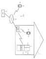
도 1은 일 실시 형태의 촬상 시스템을 모식적으로 도시한 도면,
도 2(a) 및 2(b)는, 촬상 장치의 외관을 나타낸 정면도 및 내부 구조를 도시한 종단 측면도,
도 3은 촬상 장치 및 실내 촬상 시스템의 전기적 구성을 모식적으로 도시한 도면,
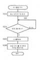
도 4는 메인 처리의 플로차트,
도 5는 제1 촬상 처리의 플로차트,
도 6은 제2 촬상 처리의 플로차트이다.1 is a diagram schematically showing an image pickup system according to an embodiment,
2 (a) and 2 (b) are a front view showing the external appearance of the image pickup apparatus and a longitudinal side view showing the internal structure,
3 is a diagram schematically showing an electrical configuration of an image pickup apparatus and an indoor image pickup system,
4 is a flowchart of the main processing,
5 is a flowchart of the first imaging process,
6 is a flowchart of the second image pick-up process.
이하, 일 실시 형태에 대하여 도 1 ~ 도 6을 참조하면서 설명한다.Hereinafter, one embodiment will be described with reference to Figs. 1 to 6. Fig.
도 1에 도시하는 바와 같이, 본 실시 형태의 촬상 시스템(100)은, 가전제품인 냉장고(1), 실내를 촬상하기 위한 촬상 장치(2), 액세스 포인트(3), 휴대 단말기(4) 등의 외부 장치를 구비하고 있다. 이 중, 액세스 포인트(3)는, 촬상 장치(2) 등과의 사이에 통신을 행하기 위한 것으로, 외부 네트워크(5)에 접속되어 있다. 이 액세스 포인트(3)에 의해서, 원격지의 휴대 단말기(4)나 서버(6) 등과 촬상 장치(2)측 또는 냉장고(1)측 사이를 외부 네트워크(5)를 통해 통신 가능하게 접속하고 있다. 본 실시 형태에서는, 촬상 장치(2)와 액세스 포인트(3)의 사이, 액세스 포인트(3)와 휴대 단말기(4)의 사이, 및 냉장고(1)와 액세스 포인트(3)의 사이는, 예를 들어 Bluetooth(등록상표)에 의한 무선 통신으로 각각 통신이 이루어진다.1, an image capturing
휴대 단말기(4)는, 촬상 장치(2)로 촬상된 화상 데이터를 표시하는 표시 화면(4a)를 갖는다. 휴대 단말기(4)는, 통신 단말기로서 소위 스마트 폰(고기능 휴대 전화)을 상정하고 있다. 다만, 통신 단말기로서는, 휴대 단말기(4)에 한정되지 않고, 예를 들어 타블렛형의 PC 등이어도 된다. 이 휴대 단말기(4)가 주택(7) 안에 위치하고 있는 경우에는, 액세스 포인트(3)와의 사이에 근거리 무선 방식에 의해 통신 가능하게 접속된다. 또한, 휴대 단말기(4)가 주택(7) 밖에 위치하고 있는 경우에는, 광역 통신에 의해 외부 네트워크(5)를 통하여 액세스 포인트(3)와의 사이에 통신 가능하게 접속된다. 또한 휴대 단말기(4)는, 주택(7) 안에 있어도 광역 통신에 의해 외부 네트워크(5)를 통하여 액세스 포인트(3)에 접속하는 것이 가능한 동시에, 주택(7) 안에서는, 액세스 포인트(3)를 통하지 않고 촬상 장치(2)측이나 냉장고(1)측과 직접적으로 통신 가능하다.The
서버(6)는, 주지의 컴퓨터 시스템에 의해 구성되어 있고, 촬상 장치(2)로 촬상한 화상 데이터를 기억하는 기억 수단을 구비한다. 서버(6)의 기억 수단은, ROM 등의 비휘발성 메모리, RAM 등의 휘발성 메모리, EEPROM 등의 전기적으로 개서 가능한 비휘발성 메모리를 포함한다. 서버(6)의 기억 수단에는, 촬상 장치(2)에 액세스하기 위한 정보(예를 들면 IP주소) 등도 기억되어 있다. 상기한 휴대 단말기(4)나 서버(6) 등은, 상기 화상 데이터에 기초하여 표시를 행하기 위한 표시 수단(도 1에서는 휴대 단말기(4)의 표시 화면(4a)만 표시)을 구비한다. 이들 휴대 단말기(4)나 서버(6) 등은, 외부의 장치에 상당한다. 또한, 촬상 장치(2)에 표시 수단을 설치해도 된다.The server 6 is constituted by a well-known computer system and includes a storage means for storing image data taken by the
상기 냉장고(1) 등의 가전제품은 네트워크화되어 있다(도 3의 통신 어댑터(34) 참조). 이 네트워크화에 의해 각 가전제품의 소비 전력을 사용자가 볼 수 있는 형태로 제공하는 「가시화」를 실현할 수 있다. 또한 네트워크화에 의해 여름 철의 낮 등의 전력 수요가 커지는 시간대에 있어서의 전력 소비를 저감하는 피크 시프트, 일반 가정의 정격을 넘는 전력의 순간적인 사용을 회피하는 피크 컷 등의 전력 컨트롤이나, 가전제품의 고장 진단 등, 사용 편리성이나 쾌적성 또는 편리성을 제공하기 위한 시스템을 제공하는 것이 가능해진다.The household appliances such as the
또한, 본 실시 형태의 촬상 장치(2)는, 예를 들어 냉장고(1)에 있어서, 그 실내 모습(즉 고내의 물품 저장 상태 등)을 촬상하도록, 사용자에 의해 배치된다. 그리고 각 가전제품의 각종 정보, 및 촬상 장치(2)로 촬상된 화상 데이터 등을 서버(6)에 기억시키고, 또한 휴대 단말기(4)에 송신하도록 구성되어 있다. 이로써, 원격지에서도 언제라도 외부 네트워크(5) 등을 통하여 휴대 단말기(4) 등에 의해 이들 정보를 참조하는 것이 가능해진다.The
저장고로서의 냉장고(1)에 있어서 그 상부의 냉장실은 양문식의 좌우 문(1a, 1b)에 의해 개폐된다. 예를 들어, 문(1a, 1b)은 냉장실의 좌우 양측부의 경첩부에 회동 가능하도록 피봇된 회동식문이다. 이 문(1a, 1b) 중, 좌우 방향 중 치수가 큰 오른쪽 문(1b)의 이면측(안측의 도시하지 않는 도어 포켓)에 촬상 장치(2)가 배치된다(도 1의 2점 쇄선 참조). 이 외, 촬상 장치(2)는, 냉장실 아래 측 야채실의 서랍식 문(1c)의 이면 측에 배치하는 등 고내의 상태를 파악하기 쉬운 위치에 세트 하면 된다.In the
냉장고(1)에서의 문(1a~1c)의 앞면은, 절연성의 유리 재료 즉 전파를 투과 시키는 비금속제 재료인 유리판으로 덮여 있다. 문(1a~1c)의 내부에는, 단열재인 우레탄이 충전제로서 충전되어 있다. 문(1a~1c)의 뒷면은, 비금속 수지제의 내판으로 구성되어 있다. 그러므로, 촬상 장치(2)로부터의 무선 통신용의 전파는, 문(1a~1c)에 있어서 금속판 등을 이용하는 경우에 비해 투과하기 쉬워진다. 특히, 문(1a, 1b)과 같이 좌우 여닫이문인 경우에는, 촬상 장치(2)를 도 1의 2점 쇄선으로 도시하는 바와 같이 오른쪽 문(1b)의 개방단 측에 배치함으로써, 냉장실의 좌우 방향의 중앙부가 되고, 또한 양문(1a, 1b)의 틈새로부터 전파가 냉장고 밖으로 쉽게 나가게 할 수 있다. 따라서, 해당 촬상 장치(2)의 배치에서는, 문(1a, 1b)의 앞면이 금속재료로 형성되어 있는 경우에도, 전파가 냉장고 밖으로 쉽게 나갈 수 있고, 문(1a, 1b) 내부가 우레탄으로 충전되어 있기 때문에, 전파를 차단할 가능성이 적다.The front faces of the
냉장고(1)에서는, 단열재로서 우레탄 대신 또는 우레탄과 함께, 진공 단열재를 이용한 구성으로 해도 된다. 진공 단열재는, 금속제의 얇은 부재(예를 들면 알루미늄 박)와 예를 들어 합성 수지제의 필름 부재를 맞붙여 래미네이트 가공한 필름으로 유리 섬유 등의 심재(芯材)를 감싸므로써, 예를 들어 장방형의 얇은 판자 형상으로 형성한 구성에 있다. 이 진공 단열재를, 냉장고(1)의 케이스나 문의 내부 부재로서 이용하는 경우, 촬상 장치(2) 근방을 피해 배설함으로써, 전파가 밖으로 나가기 쉬워진다. 이로써, 냉장고(1)의 단열성을 최대로 유지하면서도 전파를 쉽게 보낼 수 있고 냉장고(1)의 통신 어댑터(34)를 통하지 않고도 촬상 장치(2)로부터 정보를 외부의 장치로 송신할 수 있다.In the
이어서 촬상 장치(2)에 대해 설명한다.Next, the
도 2(a)에 도시하는 바와 같이, 촬상 장치(2)는, 외곽을 이루는 케이스(10)가 대략 직육면체 형상으로 형성되어 있다. 촬상 장치(2)는, 냉장고(1)의 고내와 같은 암실에서도 촬상 가능하게 하는 조명 수단을 갖는 카메라이다. 케이스(10)에는, 촬상 렌즈(12) 및 촬상 라이트(13)와 광 센서(14a)가 노출되도록 설치되어 있다. 이하에서는, 해당 렌즈(12) 등이 노출되는 측(도 2(b)에서는 우측)을 케이스(10)의 메인 면(10a)으로 하고, 반대측을 뒷면으로 한다. 또한, 렌즈(12) 및 라이트(13)가 직접 노출되어 있는 것이 아니라, 그 표면을 커버 등으로 덮는 구성으로 해도 된다.As shown in Fig. 2 (a), in the
도 2(b)에 도시하는 바와 같이 케이스(10) 안에는, 제어 기판(15), 전지(16), 통신 모듈(17)이 수용되어 있다. 제어 기판(15)에는, 예를 들어 LED로 이루어진 2개의 라이트(13, 13)가 상기 렌즈(12)를 사이에 두는 위치에 실장되어 있다. 즉, 라이트(13)는 그 조사 방향과 촬상 장치(2)의 촬상 방향이 같은 방향으로, 촬상시에 조사하는 빛에 의해 암실 안을 비추도록 되어 있다. 라이트(13)는, 광 센서(14a)와 함께 조명 수단을 구성한다. 또한 제어 기판(15)에는, CCD나 CMOS 등의 주지의 촬상 소자를 갖는 촬상부(11, 도 3 참조), 촬상측 제어부(18) 등이 설치되어 있다.As shown in Fig. 2 (b), a
전지(16)는, 도 3에 도시한 검지부(14)나, 촬상측 제어부(18), 통신 모듈(17) 등에 전력을 공급한다. 즉, 촬상 장치(2)는 전지(16)를 내장하고 있어, 전원 케이블 등이 필요하지 않다. 그러므로 촬상 장치(2)를 임의의 장소에 설치할 수 있어, 본 실시 형태의 냉장고(1)와 같이 문을 갖는 저장고 안에 설치하는 것이 가능해진다.The
통신 모듈(17)은, 촬상부(11)로 촬상한 고내의 화상 데이터를 외부 장치로 송신하거나 후술하는 시각 정보를 수신하기 위한 통신부이다. 상기 화상 데이터는, 액세스 포인트(3)를 통하여 휴대 단말기(4)나 서버(6) 등에 송신된다. 서버(6)에서는 송신된 화상 데이터가 기억된다. 여기서 화상 데이터란, 고내의 화상을 포함한 촬상 데이터이다. 화상 데이터는, 예를 들어 비트 맵 형식이나 JPEG 형식 혹은 MPEG 형식 등의 주지의 포맷의 데이터(정지화면, 동영상), 그 데이터를 압축이나 암호화 또는 화상 처리함으로써 변환한 데이터 등, 고내의 모습을 휴대 단말기(4) 등으로 확인할 수 있는 데이터라면, 어떠한 형상이어도 된다.The
그리고 상기 프레임(10)의 측부에는, 각종 스위치류로 이루어진 조작부(20, 도 3 참조)가 설치되어 있다. 조작부(20)는, 전원 스위치(20a)나 모드 스위치(20b), 세트 스위치(20c)라고 하는 촬상에 관한 스위치류로 구성되어 있다. 구체적으로 전원 스위치(20a)는, 촬상 장치(2)의 전원을 온/오프하기 위한 조작부이다. 모드 스위치(20b)는 모드 설정 수단이다. 모드 스위치(20b)를 조작함으로써, 예를 들어 시각 설정 모드, 제1 촬상 모드, 제2 촬상 모드 중에서 모드를 선택할 수 있다.On the side of the
상기 시각 설정 모드는, 내부 시계인 RTC(18d, 도3 참조)의 시각을 설정하기 위한 모드이다. RTC(18d)의 시각을 참조하여, 촬상측 제어부(18)는, 촬상 장치(2)에서 지정 시간에 정확한 동작이나 제어 또는 계시(計時)를 실시한다. 촬상 장치(2)는, 외부 네트워크(5)와 통신 모듈(17)을 통하여 통신이 가능하다. 촬상 장치(2)는, 시각 설정 모드에서는 예를 들어 상기 서버(6)와는 별도로 도시하지 않은 시각 서버(시간 정보를 송신할 수 있는 서버)로부터 취득한 시각을 사용하여 RTC(18d)의 시각을 설정한다.The time setting mode is a mode for setting the time of the RTC 18d (see FIG. 3) as the internal clock. With reference to the time of the RTC 18d, the imaging-
상기 제 1 촬상 모드는, 소정 주기로 정기적으로 촬상하는 모드이다. 촬상측 제어부(18)는, RTC(18d)의 시각을 참조하여, 제1 촬상 모드에 대한 정확한 주기(예를 들면 24시간 주기)로, 지정 시간(예를 들면 오후 3시 등)에 촬상을 자동적으로 실시한다. 따라서 사용자는, 촬상 장치(2)를 냉장고(1)의 고내에 배치하여 제1 촬상 모드로 설정하면, 해당 배치 위치의 촬상 장치(2)에서 촬상된 최신 화상 데이터, 즉 고내의 식품 재료의 종류 등을 휴대 단말기(4) 등으로 확인할 수 있다. 또한, 지정 시간은, 초기값으로 미리 설정된 시간이어도 되고, 조작부(20)로 사용자가 시간을 지정하는 구성으로 해도 된다.The first imaging mode is a mode in which imaging is performed periodically at predetermined intervals. The imaging
상기 제 2 촬상 모드는, 세트 스위치(20c) 조작을 하고 나서 소정 시간 경과 후에 촬상하는 모드이다. 여기서의 소정 시간이란, 촬상 장치(2)를 세트하고 나서 자동적으로 촬상될 때까지의 적당한 소요 시간(예를 들면 10초)이다. 따라서, 제2 촬상 모드에서는, 냉장고(1) 문(1b)의 상기 도어 포켓에 촬상 장치(2)를 세트한 경우, 세트 스위치(20c)를 조작하고 나서 예를 들어 10초 후에, 해당 문(1b)을 닫은 상태로 자동적으로 촬상을 실시할 수 있다. 따라서, 제2 촬상 모드로 설정하면, 문(1b)을 폐쇄한 상태로 촬상한 화상을 휴대 단말기(4) 등으로 확인함으로써, 촬상 장치(2)의 세트 위치가 적절한지의 여부를 알 수 있다. 이와 같이, 제2 촬상 모드는, 말하자면 촬상 장치(2)의 시험 촬영(배치 확인용) 모드이다.The second imaging mode is a mode in which imaging is performed after a lapse of a predetermined time from the operation of the
상기 세트 스위치(20c)는, 예를 들어 모드 스위치(20b)로 모드를 선택하여 결정하거나, 또는 선택한 모드를 개시하기 위해 조작되는 결정 키이다. 이들 스위치(20a ~ 20c)는, 상기한 종류나 조작 방법으로 한정되는 것은 아니다. 예를 들어 모드 스위치(20b)는, 각종 모드를 슬라이드 조작으로 선택하여 결정하도록 구성해도 되고, 모드의 수를 증감해도 된다.The
또한 본 실시 형태의 촬상측 제어부(18)는, 어떤 모드로 촬영된 화상 데이터인지를 구별할 수 있도록, 예를 들어 제2 촬상 모드의 화상 데이터에, 해당 제 2 촬상 모드에서의 화상인 것을 표시하는 식별 데이터를 부가한다. 또한, 촬상측 제어부(18)는, 제1 촬상 모드의 화상 데이터와 제2 촬상 모드의 화상 데이터의 적어도 어느 하나 또는 쌍방에 식별 데이터를 부가하여 양 모드의 화상 데이터를 구별할 수 있도록 구성해도 된다.In addition, the imaging-
상기 촬상측 제어부(18)는, 마이크로 컴퓨터를 메인으로 구성되어, 촬상 장치(2) 전체의 제어를 맡는다. 도 3에 도시하는 바와 같이 촬상측 제어부(18)는 내부에 CPU(18a), ROM(18b), RAM(18c), RTC(18d) 등을 갖는다. 촬상측 제어부(18)는 촬상부(11)에 의한 촬상 타이밍의 제어, 촬상 라이트(13)의 점등 등, 촬상시의 촬상 환경을 조정하는 제어를 실시한다. 또한 촬상측 제어부(18)는, 통신 모듈(17)에 의한 화상 데이터의 송신을 위한 제어나, 촬상한 화상의 보정 등의 화상 처리를 실시하는 제어 수단으로서 구성되어 있다. ROM(18b)에는 상기 복수 모드로의 처리를 실행하기 위한 제어 프로그램이 기억되어 있다.The imaging-
촬상측 제어부(18)에는 촬상부(11), 라이트(13), 조작부(20), 통신 모듈(17), 검지부(14)가 접속되어 있다. 상기 검지부(14)는 예를 들어 광 센서(14a), 소리 센서(14b)를 포함한다. 광 센서(14a)는, 촬상 장치(2)의 주변의 조도를 검출하는 조도 센서이며, 소정의 파장 대역의 빛 에너지를 검출한다. 광 센서(14a)로 검출된 빛 에너지는, 전기신호로 변환되어 촬상측 제어부(18)에 출력된다. 소리 센서(14b)는 미리 설정되어 있는 주파수 대역에서 발생되는 소리이며, 본 실시 형태의 고내에서는 후술의 패널 부저(29)나 실내 부저(33)로부터 발생되는 소리 에너지를 검출한다. 소리 센서(14b)로 검출된 소리 에너지는 전기신호로 변환되어 촬상측 제어부(18)에 출력된다.An
구체적으로는 후술한 바와 같이, 촬상 장치(2)는, 항상 통상 동작 모드보다 상대적으로 소비 전력이 적은 저전력 모드에서 대기하고, 상기 제 1 촬상 모드나 제2 촬상 모드로 촬상할 때, 통상 동작 모드로 복귀하여 고내를 촬상한다. 이 때 촬상한 화상 데이터는, 통신 모듈(17)에 의해 외부의 장치 측으로 송신하는 일방향 통신을 실시한다. 한편 시각 설정이 필요할 때, 즉 시각 설정 모드에서는, 통상 동작 모드로 통신 모듈(17)측에서의 요구 신호를 따라, 시각 취득 또는 수신을 실시한다(쌍방향 통신). 이와 같이, 본 실시 형태에서는, 외부 장치측으로의 통신 방향인 단방향 통신인 일방향 통신과, 전파를 통하여 촬상 장치(2)와 외부 장치 사이의 쌍방향으로 데이터를 통신하는 쌍방향 통신이 가능하게 된다. 이와 같은 일방향 통신은, 송신과 수신의 쌍방을 실시할 필요가 없고, 시각 설정 모드에서 쌍방향 통신을 실시하는 빈도는, 촬상하는 빈도에 비해 적다. 그러므로 일방향 통신은, 소비 전력의 관점에서도 바람직한 구성이라 할 수 있다More specifically, as will be described later, the
도 3에 도시하는 냉장고(1)의 고측 제어부(21)는, 마이크로컴퓨터를 메인으로 구성하여, 냉장고(1) 전체의 제어를 맡는다. 고측 제어부(21)는, 내부에 CPU(21a), ROM(21b), RAM(21c), 타이머(21d) 등을 구비한다. 고측 제어부(21)에는, 주지의 냉동 사이클 등으로 구성되는 냉장용 냉각 기구(25)와 냉동용 냉각 기구(26)가 접속되는 동시에, 냉장고(1)의 각 문의 문 센서(24)와 후술하는 조작 패널(22)과 온도 센서(23)가 접속되어 있다. 고측 제어부(21)는 조작 패널(22)로 설정된 운전 상태가 되도록, 온도 센서(23)로 검출된 고내의 온도나 문 센서(24)로 검출된 문의 개폐 상태 등에 기초하여, 각 냉각 기구(25, 26)를 각각 구동 제어한다.The high-
상기 조작 패널(22)에는, 도시하지 않는 패널 표시기나 패널 LED 외, 패널 부저(29)가 설치되어 있다. 패널 표시기나 패널 LED는 설정 값을 표시하거나 조작 스위치를 점등시킨다. 패널 부저(29)는 압전 부저 등으로 구성되어 조작에 따라 음성(소리 에너지)을 발생시킴으로써, 조작 내용을 통지한다. 또한 패널 부저(29)는, 예를 들어 6kHz의 소리를 출력할 수 있다. 패널 부저(29)는 촬상 장치(2)에 대해서 촬상에 관한 정보를 소정의 명동(鳴動) 패턴으로 전달하기 위한 소리 에너지를 발생시키는 전달 수단으로서 기능한다.The
또한, 도 3에 도시하는 실내 부저(33)는 예를 들어 냉장실 등에 설치된 압전 부저이며, 전달 수단으로서 소리 에너지를 발생한다. 이 소리 에너지는, 예를 들어 가청 지역으로부터 벗어난 20kHz의 음성이며, 소리 센서(14b)로 검출된다. 한편, 송풍기(31)는 통상적인 동작으로는 냉장고(1) 안의 냉기를 순환시키기 위해서 설치되어 있다. 이 송풍기(31)는, 예를 들어 회전수를 통상의 동작보다 크게 함으로써, 바람 가르는 소리나 모터음 등의 소리 에너지를 발생시키는 것이 가능하게 된다. 이들 부저(29, 33) 및 송풍기(31)는 모두 택일적으로 전달 수단으로서 기능시킬 수 있다.The
실내 조명(30) 및 실내 LED(32)는 모두 냉장실 등에 설치되어 있다. 실내 조명(30)은 문이 개방되었을 때에 점등하여 빛 에너지를 발생시킨다. 실내 조명(30)은 고측 제어부(21)의 제어에 의해 점멸 가능하게 되어 있다. 실내 LED(32)는 촬상 장치(2)에 대한 정보 전달을 위해 광 센서(14a)에 의해 검출 가능한 소정 주파수 대역의 빛(빛 에너지)을 발생한다. 실내 LED(32)는 촬상에 관한 정보를 표시하기 위해 소정 점멸 패턴으로 점멸시킬 수 있다. 이와 같이 실내 조명(30) 및 실내 LED(32)는, 모두 촬상 장치(2)에 대하여 빛 에너지로 촬상에 관한 정보를 전달하는 전달 수단으로 기능시킬 수 있다. 그러므로 실내 조명(30) 및 실내 LED(32)는, 택일적으로 이용할 수 있다.The indoor lighting (30) and the indoor LED (32) are all installed in a refrigerating room or the like. The
통신 어댑터(34)는, 냉장고(1)에 착탈 가능하게 설치되어 있다. 통신 어댑터(34)는, 액세스 포인트(3)나 실내의 휴대 단말기(4) 등과의 사이에 통신을 행한다. 통신 어댑터(34)는, 액세스 포인트(3)를 통하지 않고, 촬상 장치(2)와의 사이에 직접적으로 통신을 행하는 것도 가능한 구성으로 되어 있다. 통신 어댑터(34)는, 상기한 「가시화」등에도 이용되는 것에서, 냉장고(1)가 동작하고 있는 상태에서는 기본적으로 항상 작동하고 있다. 또한 도 1에는 냉장고(1)만을 도시하고 있지만, 통신 어댑터(34)는, 에어컨 등의 다른 가전제품에도 설치함으로써, 가전제품을 네트워크화할 수 있다.The
외부 장치인 예를 들어 휴대 단말기(4)와 촬상 장치(2) 사이의 통신 수단은, 상기 통신 모듈(17), 통신 어댑터(34), 액세스 포인트(3), 외부 네트워크(5) 등으로 구성된다. 즉, 휴대 단말기(4)와 촬상 장치(2) 사이의 통신은, 상술한 전파에 의해 냉장고(1)의 통신 어댑터(34)를 통하지 않고 직접적으로 행할 수 있는 한편, 해당 통신 어댑터(34)를 통하여 간접적으로 행할 수도 있다. 후자인 경우 상기 전달 수단에 의해 촬상 장치(2)로 정보를 전달하는 등 하여, 촬상 장치(2)(제어부(18))와 냉장고(1)(제어부(21)) 사이의 정보 교환을 행한다. 즉 촬상에 관한 정보를 예를 들어 상기 점멸 패턴 또는 명동 패턴에 대하여 일반적인 냉장고(1)의 사용 상태에서는 발생할 수 없는 패턴으로 알린다. 이 때, 촬상측 제어부(18)에 의해 해당 점멸 패턴 또는 명동 패턴에 관하여 미리 설정된 데이터 테이블을 조합(照合)함으로써, 촬상에 관한 정보 내용을 식별할 수 있다. 이하의 작용 설명으로는, 휴대 단말기(4)와 촬상 장치(2) 사이의 통신을 직접적으로 행하는 경우, 즉 냉장고(1)의 통신 어댑터(34)의 생략이 가능한 구성인 것을 전제로 하여 설명한다.The communication means between the external device such as the
이어서, 상기 구성의 작용에 대하여 설명한다.Next, the operation of the above configuration will be described.
여기서, 사용자는 촬상 장치(2)를 주택(7) 실내의 원하는 위치에 배치한다. 상기와 같이 촬상 장치(2)는 촬상 라이트(13)를 가짐으로써, 냉장고(1)의 고내와 같은 암실에 배치할 수 있다. 이하에서는, 도 1에 파선으로 도시하는 바와 같이, 냉장고(1)의 오른쪽 문(1b)의 상기 도어 포켓에, 해당 문(1b)을 폐쇄한 상태로 촬상 장치(2)의 주면(10a)이 냉장실 구석부분을 향하도록 배치하여, 고내를 촬상하는 것으로 한다. 또한, 도 4~도 6의 플로차트는, 촬상 장치(2)의 전원 스위치(20a)의 ON 조작에 의해 개시되어 촬상측 제어부(18)에 의해 실행되는 제어 프로그램의 흐름을 나타내고 있다.Here, the user places the
즉, 촬상 장치(2)는, 전원 스위치(20a)로 전원을 ON으로 하면(도 4의 단계 S1), 슬립 모드로 이행된다(단계 S2). 이 슬립 모드는 통상적인 동작 모드보다 전력 소비가 적은 저전력 모드에 상당한다. 즉, 예를 들어 쌍방향 통신이 가능한 구성으로 통신 모듈(17)을 항상 동작하게 하면, 전력 소비가 커져, 하루 또는 며칠 안에 전지(16) 교환(또는 충전)이 필요한 사태가 생길 수 있다. 여기서, 촬상측 제어부(18)는, 슬립 모드로 대기하고 있는 상태에서, 조작부(20)에서의 설정 조작의 유무 등을 판정한다.That is, the
여기서, 촬상 장치(2)에서의 쌍방향 통신은, 사용자가 모드 스위치(20b)를 조작하여 시각 설정 모드로 설정한 경우에 행해진다(단계 S3에서 '예', 단계 S4). 이 경우, 도시는 생략 하지만, 촬상측 제어부(18)은 통상 동작 모드로 복귀하고, 통신 모듈(17)측에서의 요구 신호를 따라, 외부 네트워크(5)를 통하여 상기 시각 서버로부터 시각 정보의 수신을 행한다. 이것에 의해, RTC(18d)의 시각이 어긋나있었다고 해도, 취득한 시각 정보로 RTC(18d)의 시각 교정을 실시할 수 있다. 이로써, 단계 S4에서 시각 설정 처리를 끝내면, 다시 슬립 모드로 이행(단계 S2로 리턴한다)함으로써, 소비 전력을 크게 저감할 수 있다Here, the bidirectional communication in the
한편, 촬상 장치(2)를 상기 도어 포켓(고내)에 설치하고 바로, 카메라에 찍힌 것을 확인하고 싶은 경우에는, 모드 스위치(20b)를 조작하여, 테스트 촬영 모드인 제2 촬상 모드를 선택한다(단계 S3에서 '아니요', 단계 S5에서 '아니요', 단계 S7에서 '예'). 이 경우, 촬상측 제어부(18)는, 단계 S8로 이행되어 제2 촬상 처리를 실행한다(도 6 참조). 제2 촬상 처리에 있어서, 촬상측 제어부(18)는, 통상적인 동작 모드로 복귀(단계 S21)하고, 상기 세트 스위치(20c)를 조작하고 나서 소정 시간의 경과 여부를 판단한다(단계 S22). 이 소정 시간은, 상술한 바와 같이 촬상 장치(2)를 세트하고 나서 촬상할 때까지의 적당한 소요 시간(예를 들면 10초)이며, 해당 세트 후에 문(1b)을 닫은 상태로 촬상 장치(2)에 의한 자동적인 촬상이 행해진다(단계 S23). 또한 이 촬상 때, 촬상측 제어부(18)는, 광 센서(14a)의 검출 신호에 기초하여, 소정의 조도에 못 미친다고 판단된 경우, 고내를 비춘다. 그리고 촬상측 제어부(18)는, 촬상에 의해 생성된 화상 데이터를, 테스트 촬영임을 나타내는 식별 데이터와 함께 휴대 단말기(4)로 송신하거나 서버(6)로 송신하여 기억시킨다(단계 S24). 이로써, 제2 촬상 처리를 끝내면, 다시 슬립 모드로 이행된다(단계 S2로 리턴 한다).On the other hand, when it is desired to confirm that the
테스트 촬영 결과, 그 촬상 장치(2)의 배치로 정기적인 촬상을 행하고 싶은 경우, 모드 스위치(20b)를 조작하여, 제1 촬상 모드를 선택한다(단계 S5에서 '예'). 이 경우, 촬상측 제어부(18)는, 단계 S6으로 이행되어 제1 촬상 처리를 실행한다(도 5 참조). 제1 촬상 처리로는, 미리 정해진 주기에 정기적으로 촬상할 수 있도록, 상기 지정 시간이 도래(단계 S11에서 '예')할 때까지, 슬립 모드에서 대기한다. 그리고 촬상측 제어부(18)는 지정 시간의 도래에 의해 통상적인 동작 모드로 복귀하고(단계 S12), 고내를 촬상한다(단계 S13). 이때 촬상측 제어부(18)는, 제2 촬상 모드와 마찬가지로, 고내를 비추며 촬상하고, 그 화상 데이터를 휴대 단말기(4)나 서버(6)로 송신한다(단계 S14). 이후, 촬상측 제어부(18)는, 다시 슬립 모드로 이행된다(단계 S16). 이로써, 촬상측 제어부(18)는, 다른 모드로 전환될 때까지(단계 S15에서 '아니요'), 단계 S14~S16를 반복하여 실행함으로써 정기적인 촬상을 행한다.As a result of the test photographing, if it is desired to perform periodic imaging with the arrangement of the
휴대 단말기(4)에서는, 촬상 장치(2)를 설치할 때, 또는 정기적으로 촬상되어 수신된 화상 데이터에 기초하여, 그 화면(4a)에 고내의 식품의 화상을 표시할 수 있다. 이 경우, 휴대 단말기(4)는 상기 식별 데이터에 기초하여 제2 촬상 모드로 촬상된 화상을 식별할 수 있다. 그러므로 예를 들어 화면(4a)상에서 제1 촬상 모드로의 화상과 함께 「00일 촬영」이라고 표시하거나 제2 촬상 모드에서의 화상과 함께 「테스트 촬영」이라고 표시해도 된다The
이상으로 설명한 바와 같이, 본 실시 형태의 촬상 시스템(100)은, 촬상하는 장치와 외부의 장치가 통신 수단에 의해 통신 가능하게 구성된 것이고, 촬상에 관한 설정 조작을 행하기 위한 조작부(20)와, 조작부(20)의 설정 조작에 기초하여 촬상하는 장치로서 정기적으로 촬상하여 화상 데이터를 생성하는 촬상 장치(2)와, 화상 데이터에 기초한 표시를 행하기 위한 표시 수단을 구비한다As described above, the
이로써, 촬상 장치(2)와 외부의 장치가 통신 가능하게 구성되어 촬상 장치(2)에서 촬상한 화상 데이터에 기초하여 표시 수단에 표시를 행할 수 있다. 따라서, 조작부(20)의 설정 조작에 기초하여 정기적으로 촬상한 화상을, 표시 수단에 의해 확인할 수 있어 편리성이 높아 실용하기에 적절하다고 할 수 있다.Thereby, the
또한, 촬상에 관한 설정 조작을 행하기 위한 조작 수단은, 촬상 장치(2)의 조작부(20)로 한정하는 것이 아니고, 외부의 장치의 조작부이어도 된다. 즉 예를 들어, 휴대 단말기(4)의 터치 패널이나 서버(6)의 키보드(모두 도시 생략) 등을 조작 수단으로서 상기 통신 수단을 통하여 촬상 장치(2)에 대하여 촬상에 관한 설정 조작을 행하도록 구성한 경우에서도, 상기와 같은 효과를 갖는다.The operation means for performing the setting operation relating to the image pickup is not limited to the
상기 표시 수단은 외부의 장치에 설치되어 촬상 장치(2)에서 생성된 화상 데이터를, 통신 수단에 의해 외부의 장치로 송신한다. 이로써, 촬상 장치(2)에서 촬상한 화상을, 해당 촬상 장치(2)로부터 떨어진 외부 장치의 표시 수단에서 확인할 수 있다.The display means is provided in an external apparatus and transmits image data generated by the image pickup apparatus (2) to an external apparatus by a communication means. Thereby, the image picked up by the
상기 촬상 장치(2)는, 문이 있는 저장고에, 그 고내를 촬상하도록 배치되어, 조작부(20)의 설정 조작을 하고 나서 소정 시간 경과 후에 해당 고내를 촬상하는 테스트 촬영을 실시한다. 이로써, 촬상 장치(2)를 저장고에 배치한 후, 문을 닫는 시간을 고려한 촬상 타이밍에서 테스트 촬영을 실시할 수 있다. 이와 같이 소정 시간을 설정함으로써, 저장고에 촬상 장치(2)를 세트한 경우, 즉석으로 해당 촬상 장치(2)의 화상을 확인할 수 있어 편리성을 한층 향상시킬 수 있다. 특히, 촬상 장치(2)가 문에 장착되어 있는 경우, 문을 닫은 후의 저장고 안(실내)을 테스트용으로 찍어야 하기 때문에, 상기 소정 시간을 설정하면 효과적이다.The
상기 촬상 장치(2)는 암실에 배치되고, 적어도 해당 촬상 장치(2) 또는 암실에 조명 수단을 구비하며, 촬상 장치(2)는 촬상 시에 조명 수단에 의해 암실 안을 비추어 촬상한다. 이로써, 암실이 소정의 조도에 못 미친 경우에도, 그 암실 안(상기 실시 형태에서는 피사체로서의 식품(고내))을 확인할 수 있는 화상을 얻을 수 있다.The
상기 촬상 장치(2)는, 외부의 장치에 대해 화상 데이터를 일방향 통신으로 송신한다. 이로써, 예를 들어 쌍방향 통신으로 언제 수신할지가 불명확하기 때문에 통신 모듈(17)을 항상 동작시킬 필요가 없어, 소비 전력을 저감 할 수 있다. 또한 본 실시 형태에서는 모드를 바꾸어 쌍방향 통신을 행하고 있는데, 일방향 통신인 송신측과 수신측이 고정된 통신 형태(상기 변환을 할 수 없는 형태) 이어도 된다.The image capture device (2) transmits image data to an external device via one-way communication. This makes it unnecessary to always operate the
상기 촬상 장치(2)는, 전지식으로 항상 통상 동작 모드보다 상대적으로 전력 소비가 적은 저전력 모드에서 대기하고 있어, 촬상 시에 통상적인 동작 모드로 복귀하여 촬상한다. 이로써, 통상적인 동작 상태인 채로 대기할 필요가 없기 때문에, 대기중의 전력 소비를 삭감할 수 있다.The
상기 외부의 장치는, 통신 수단을 통하여 취득한 화상 데이터를 기억하는 기억 수단을 갖는 서버(6)이다. 이로써, 정기적으로 얻을 수 있는 화상 데이터를 서버(6)의 기억 수단에 축적할 수 있는 동시에, 다른 외부의 장치에 의해, 서버(6)로부터 화상 데이터를 취득할 수 있다The external apparatus is a server (6) having a storage means for storing image data acquired through a communication means. Thereby, image data that can be obtained periodically can be stored in the storage means of the server 6, and image data can be acquired from the server 6 by another external apparatus
상기 외부의 장치는, 통신 수단을 통하여 취득한 화상 데이터에 기초하여 화상 표시하는 단말기측 표시 수단을 갖는 통신 단말기이다. 이로써, 통신 단말기에 있어서, 표시 수단(예를 들면 화면(4a))의 화상을 확인할 수 있어, 보다 편리하게 사용할 수 있다The external apparatus is a communication terminal having terminal display means for displaying an image based on image data acquired through communication means. Thereby, in the communication terminal, the image of the display means (for example, the
상기 표시 수단은, 소정 주기에 정기적으로 촬상한 화상 데이터의 화상과, 조작부(20)의 설정 조작을 하고 나서 소정 시간 경과 후에 촬상한 테스트 촬영의 화상 데이터의 화상을 구별하여 표시한다. 이로써, 예를 들어 전자와 후자의 화상 데이터가 모두 표시 수단으로 표시 가능한 경우에도, 양자의 화상을 판별할 수 있어 테스트 촬영의 화상을 용이하게 파악할 수 있다.The display means displays images of image data periodically photographed at regular intervals and images of image data of test photography images taken after a predetermined period of time after the setting operation of the
상기 촬상 장치(2)는 소정의 주기에 정기적으로 촬상한 화상 데이터와 조작부(20)의 설정 조작을 하고 나서 소정 시간 경과 후에 촬상한 테스트 촬영의 화상 데이터를 구별하기 위하여, 이들 화상 데이터의 적어도 어느 하나에 식별 데이터를 부가하여 외부의 장치로 송신한다. 이로써, 외부의 장치에서, 식별 데이터에 기초하여 정기적으로 촬상한 화상 데이터와 테스트 촬영한 화상 데이터가 식별되어, 각각의 화상을 구별할 수 있다.In order to distinguish image data periodically photographed at predetermined intervals and image data of a test image photographed after elapse of a predetermined period of time after setting operation of the
상기 촬상 장치(2)는, 소정의 조건을 반복하여 촬상하는 제1 촬상 모드와 조작부(20)의 설정 조작을 하고 나서 소정 시간 경과 후에 촬상하는 제2 촬상 모드의 선택이 가능하게 구성되어 있다. 이로써, 사용자의 촬상 목적에 따라, 촬상 장치(2)에서의 제1 촬상 모드로의 촬상과 제2 촬상 모드로의 촬상을 선택할 수 있어 편리성을 보다 향상시킬 수 있다The
또한, 제1 촬상 모드에서의 촬상 타이밍을 재는 소정 조건으로써 식품의 저장량이 변화한 타이밍, 또는 저장량의 변화가 추정되는 타이밍에 촬상해도 된다. 예를 들어, 냉장고(1)에, 고내의 용기나 선반(모두 도시 생략) 상의 식품의 중량을 검지하기 위한 중량 센서를 설치한다. 이 중량 센서에서 검지되는 중량 변화의 타이밍을 상기 고측 제어부(21)로 검출함으로써, 해당 타이밍에 자동적으로 촬상하도록 구성해도 된다. 이로써, 식품의 저장량이 변화했을 때만 촬상하게 되어, 쓸데 없는 촬상(통신의 로스)을 없앨 수 있다Alternatively, a predetermined condition for determining the imaging timing in the first imaging mode may be taken at a timing at which the stored amount of food changes, or at a timing at which a change in the stored amount is estimated. For example, the
상기 식품 저장량의 검지 수단으로서는, 적외선 센서나, 화상 인식 수단을 이용하여 그 센서의 신호나 화상 데이터에 기초하여 고측 제어부(21)로 식품의 저장 상태의 변화를 검지하도록 구성해도 된다. 또한, 고내의 광량을 검지하는 수광량(受光量) 검지 수단이나 문 센서(24)를 이용하여, 문이 개방되는 것에 기초하여, 고측 제어부(21)에 의해, 고내의 식품이 사용되었거나 고내에 식품이 추가로 저장되었다고 추정하도록 구성해도 된다As a means for detecting the food storage amount, a configuration may be employed in which a change in the storage state of food is detected by the high-
상기 실시 형태에서는, 촬상 장치(2)를 냉장고(1) 안에 배치했는데, 이것에 한정되는 것은 아니고, 촬상 장치(2)를 주택(7) 안의 실내나, 다른 저장고 또는 암실에 배치해도 된다.In the above embodiment, the
또한, 촬상 장치(2)는, 냉장고(1)에 착탈 가능하게 배치하는 구성으로 한정되는 것은 아니고, 고내를 촬상하도록 냉장고(1)에 일체로 설치한 구성으로 해도 된다. 촬상측 제어부(18)를 고측 제어부(21)의 내부에 설치해도 된다. 이 경우, 통신 어댑터(34)는, 통신 모듈(17)의 기능을 구비하도록 하면 된다. 도시는 생략 하지만, 이와 같이 저장고에 일체화한 촬상 장치(카메라)에 있어서, 그 고내의 벽면이나 문에 배설된 촬상부나 촬상 라이트가, 방향 변경이 가능하거나 케이블을 통하여 제어부에 접속되어 위치 변경 가능하게 구성되어 있는 경우, 상기 테스트 촬영을 실시하는 것이 유효하게 된다.The
본 발명의 몇 개의 실시 형태를 설명했지만, 이러한 실시 형태는, 예로서 제시한 것으로, 발명의 범위를 한정하는 것은 아니다. 이들 신규 실시 형태는, 이 외의 여러 가지 형태로 실시할 수 있고, 발명의 요지를 일탈하지 않는 범위에서, 여러 가지의 생략 치환 변경을 실시할 수 있다. 이들 실시 형태나 그 변형은, 발명의 범위나 요지에 포함되는 동시에, 특허 청구의 범위에 기재된 발명과 그 균등의 범위에 포함된다.Although a few embodiments of the present invention have been described, these embodiments are provided by way of example and do not limit the scope of the invention. These new embodiments can be implemented in various other forms, and various omissions and substitutions can be made without departing from the gist of the invention. These embodiments and their modifications fall within the scope and spirit of the invention, and are included in the scope of equivalents to the invention described in the claims.
1 : 저장고
1a~1c : 문
2 : 촬상 장치
4 : 통신 단말기(외부 장치)
4a : 표시 수단(단말기측 표시 수단)
6 : 서버(외부 장치)
11 : 촬상부
13, 14a : 조명 수단
17 : 통신부
20 : 조작 수단
100 : 촬상 시스템1: Storage
1a ~ 1c: door
2: Imaging device
4: Communication terminal (external device)
4a: display means (terminal side display means)
6: Server (external device)
11:
13, 14a: Lighting means
17:
20: Operation means
100: imaging system
Claims (12)
Translated fromKorean촬상에 관한 설정 조작을 행하기 위한 조작 수단과,
상기 조작 수단의 설정 조작에 기초하여 상기 촬상하는 장치로서 정기적으로 촬상하여 화상 데이터를 생성하는 촬상 장치와,
상기 화상 데이터에 기초하여 표시를 하기 위한 표시 수단,
을 구비하고,
상기 촬상 장치는, 소정의 조건으로 반복하여 촬상하는 제1 촬상 모드와, 상기 조작 수단의 설정 조작을 하고 나서 소정 시간 경과 후에 촬상하는 제2 촬상 모드의 선택이 가능하고,
제1 및 제2 촬상 모드 중 적어도 어느 하나의 촬상 모드로 촬상한 때의 일시에 관한 데이터를 부가하는 것에 의해, 상기 표시 수단에서 상기 화상 데이터에 기초한 표시와 촬상한 일시에 관한 데이터에 기초한 표시를 실시하는 것을 특징으로 하는 촬상 시스템.An imaging system configured to allow an imaging device and an external device to communicate by communication means,
An operation means for performing a setting operation relating to image pickup,
An image pickup device for periodically picking up the image pickup device and generating image data based on setting operation of the operation means;
Display means for displaying on the basis of the image data,
And,
Wherein the imaging device is capable of selecting a first imaging mode in which imaging is repeatedly performed under a predetermined condition and a second imaging mode in which imaging is performed after a predetermined time elapses after setting operation of the operating means,
By adding data concerning the date and time at the time of imaging in at least one of the first and second imaging modes, the display based on the image data and the date based on the image data is displayed on the display means To the image pickup device.
상기 표시 수단은 상기 외부의 장치에 설치되어 상기 촬상 장치로 생성된 화상 데이터 및 상기 일시에 관한 데이터를 상기 통신 수단에 의해 상기 외부 장치로 송신하는 것을 특징으로 하는 촬상 시스템The method according to claim 1,
Wherein the display means transmits the image data generated by the image pickup device and the date and time data provided to the external apparatus to the external apparatus by the communication means
상기 촬상 장치는 문이 있는 저장고의 고내를 촬상하도록 배치되고, 상기 조작 수단의 설정 조작을 하고 나서 소정 시간 경과 후에 해당 고내를 촬상하는 테스트 촬영을 상기 제2 촬상 모드로 행하는 것을 특징으로 하는 촬상 시스템3. The method according to claim 1 or 2,
Characterized in that the imaging device is arranged to take an image of the interior of a storage room with a door and to perform test photography in the second imaging mode for taking an image of the interior of the warehouse after a predetermined time has elapsed after setting operation of the operating means
상기 촬상 장치는 암실에 배치되어 적어도 해당 촬상 장치 또는 암실에 조명 수단을 구비하고, 상기 촬상 장치는, 촬상 시에 상기 조명 수단에 의해 상기 암실 안을 비추어 촬상하는 것을 특징으로 하는 촬상 시스템The method according to claim 1,
Characterized in that the imaging device is disposed in a dark room and includes illumination means at least in the imaging device or the darkroom, and the imaging device picks up the image in the dark room by the illumination means at the time of imaging,
상기 촬상 장치는, 상기 외부의 장치에 대하여 상기 화상 데이터를 일방향 통신으로 송신하는 것을 특징으로 하는 촬상 시스템The method according to claim 1,
Wherein the image pickup apparatus transmits the image data to the external apparatus via one-way communication,
상기 촬상 장치는, 전지식으로 평소에는 통상동작모드보다 상대적으로 전력 소비가 적은 저전력 모드에서 대기하고, 촬상 시에 통상동작모드로 복귀하여 촬상하는 것을 특징으로 하는 촬상 시스템.The method according to claim 1,
Wherein the image pickup apparatus waits in a low power mode in which power consumption is relatively lower than normal operation mode and is returned to a normal operation mode at the time of image pickup by the user.
상기 외부 장치는, 상기 통신 수단을 통하여 취득한 화상 데이터를 기억하는 기억 수단을 갖는 서버인 것을 특징으로 하는 촬상 시스템.The method according to claim 1,
Wherein the external device is a server having storage means for storing image data acquired through the communication means.
상기 외부의 장치는, 상기 통신 수단을 통하여 취득한 화상 데이터 및 상기 일시에 관한 데이터에 기초하여, 화상 표시와 함께 상기 일시에 관한 정보를 표시하는 단말측 표시 수단을 갖는 통신 단말인 것을 특징으로 하는 촬상 시스템.The method according to claim 1,
Wherein the external device is a communication terminal having terminal display means for displaying image information and date and time information on the basis of the image data acquired through the communication means and the date and time data, system.
상기 표시 수단은, 소정의 주기로 정기적으로 촬상한 화상 데이터의 화상과, 상기 조작 수단의 설정 조작을 하고 나서 소정 시간 경과 후에 촬상한 테스트 촬영의 화상 데이터의 화상을 구별하여 표시하는 것을 특징으로 하는 촬상 시스템The method according to claim 1,
Characterized in that the display means displays images of image data periodically photographed at predetermined intervals and images of image data of test photography images taken after a predetermined period of time from the setting operation of the operating means system
상기 촬상 장치는, 소정의 주기로 정기적으로 촬상한 화상 데이터와,
상기 조작 수단의 설정 조작을 하고 나서 소정 시간 경과 후에 촬상한 테스트 촬영의 화상 데이터를 구별하기 위하여, 이들 화상 데이터의 적어도 어느 하나에 식별 데이터를 부가하여 상기 외부 장치에 송신하는 것을 특징으로 하는 촬상시스템The method according to claim 1,
The image pickup apparatus includes image data periodically photographed at a predetermined cycle,
Characterized in that identification data is added to at least one of these image data and the image data is transmitted to the external apparatus so as to distinguish image data of the test image picked up after a predetermined period of time from the setting operation of the operating means
상기 조작 수단의 설정 조작에 기초하여 정기적으로 촬상하여 화상 데이터를 생성하는 촬상부와,
외부 장치의 통신을 수행하기 위한 통신부,
를 구비하고,
상기 촬상 장치는, 소정의 조건으로 반복하여 촬상하는 제1 촬상 모드와, 상기 조작 수단의 설정 조작을 하고 나서 소정 시간 경과 후에 촬상하는 제2 촬상 모드의 선택이 가능하고,
제1 및 제2 촬상 모드 중 적어도 어느 하나의 촬상 모드에서 촬상한 때의 일시에 관한 데이터를 부가하여, 상기 통신부를 통하여 상기 화상 데이터 및 해당 일시에 관한 데이터를 상기 외부 장치로 송신하는 것이 가능한 것을 특징으로 하는 촬상 장치.An imaging apparatus used in an imaging system having display means for performing display based on image data and operation means for performing setting operation relating to imaging,
An image pickup section for periodically picking up an image based on a setting operation of the operating means and generating image data;
A communication unit for performing communication with an external device,
And,
Wherein the imaging device is capable of selecting a first imaging mode in which imaging is repeatedly performed under a predetermined condition and a second imaging mode in which imaging is performed after a predetermined time elapses after setting operation of the operating means,
It is possible to add data relating to the date and time at the time of image pickup in at least one of the first and second image pickup modes and transmit the image data and data concerning the date and time to the external apparatus through the communication section And an image pickup device.
Applications Claiming Priority (3)
| Application Number | Priority Date | Filing Date | Title |
|---|---|---|---|
| JP2013176756AJP6092049B2 (en) | 2013-08-28 | 2013-08-28 | Imaging system and imaging apparatus |
| JPJP-P-2013-176756 | 2013-08-28 | ||
| PCT/JP2014/071562WO2015029823A1 (en) | 2013-08-28 | 2014-08-18 | Imaging system and imaging device |
Publications (2)
| Publication Number | Publication Date |
|---|---|
| KR20160032203A KR20160032203A (en) | 2016-03-23 |
| KR101717890B1true KR101717890B1 (en) | 2017-03-17 |
Family
ID=52586387
Family Applications (1)
| Application Number | Title | Priority Date | Filing Date |
|---|---|---|---|
| KR1020167003897AExpired - Fee RelatedKR101717890B1 (en) | 2013-08-28 | 2014-08-18 | Imaging system and imaging device |
Country Status (7)
| Country | Link |
|---|---|
| US (2) | US10362275B2 (en) |
| EP (1) | EP3041216A4 (en) |
| JP (1) | JP6092049B2 (en) |
| KR (1) | KR101717890B1 (en) |
| CN (5) | CN110260586B (en) |
| TW (1) | TWI558216B (en) |
| WO (1) | WO2015029823A1 (en) |
Families Citing this family (11)
| Publication number | Priority date | Publication date | Assignee | Title |
|---|---|---|---|---|
| JP6092049B2 (en) | 2013-08-28 | 2017-03-08 | 東芝ライフスタイル株式会社 | Imaging system and imaging apparatus |
| EP3489638B1 (en)* | 2016-07-20 | 2022-11-02 | Kwang-Cheol Jeong | Smart tray for measuring food intake and weight change, and weight management system comprising same |
| CN109477677A (en)* | 2016-07-21 | 2019-03-15 | 三菱电机株式会社 | Refrigerator system |
| WO2018116390A1 (en)* | 2016-12-21 | 2018-06-28 | 三菱電機株式会社 | Refrigerator |
| JP7012263B2 (en)* | 2017-10-06 | 2022-01-28 | パナソニックIpマネジメント株式会社 | refrigerator |
| FR3073997B1 (en)* | 2017-11-21 | 2021-04-16 | Airbus Operations Sas | SYSTEM OF DIFFUSION OF A TIME REFERENCE IN AN AIRCRAFT |
| JP6906455B2 (en)* | 2018-01-31 | 2021-07-21 | 日立グローバルライフソリューションズ株式会社 | refrigerator |
| CN111692830A (en)* | 2019-03-13 | 2020-09-22 | 青岛海尔电冰箱有限公司 | Control method of refrigerator and refrigerator adopting control method |
| JP7424793B2 (en)* | 2019-10-29 | 2024-01-30 | 東芝ライフスタイル株式会社 | refrigerator |
| KR20220023599A (en)* | 2020-08-21 | 2022-03-02 | 주식회사 위니아전자 | Apparatus for removing dew of camera for refrigerator and method controlling thereof |
| JP7182139B2 (en)* | 2020-09-03 | 2022-12-02 | パナソニックIpマネジメント株式会社 | Food detection device and food management system |
Citations (4)
| Publication number | Priority date | Publication date | Assignee | Title |
|---|---|---|---|---|
| JP2002295959A (en) | 2001-03-28 | 2002-10-09 | Seiko Epson Corp | Refrigerator with shooting device |
| JP2003207258A (en) | 2002-01-16 | 2003-07-25 | Toshiba Corp | refrigerator |
| JP2006080889A (en) | 2004-09-09 | 2006-03-23 | Funai Electric Co Ltd | Electrophotographic device |
| JP2006236076A (en) | 2005-02-25 | 2006-09-07 | Canon Inc | Data processing apparatus, imaging apparatus, wireless communication system, control method, and program |
Family Cites Families (66)
| Publication number | Priority date | Publication date | Assignee | Title |
|---|---|---|---|---|
| US5689641A (en)* | 1993-10-01 | 1997-11-18 | Vicor, Inc. | Multimedia collaboration system arrangement for routing compressed AV signal through a participant site without decompressing the AV signal |
| US6594688B2 (en)* | 1993-10-01 | 2003-07-15 | Collaboration Properties, Inc. | Dedicated echo canceler for a workstation |
| GB2282906B (en)* | 1993-10-13 | 1996-11-06 | Dataquill Ltd | Data enty systems |
| US5926210A (en)* | 1995-07-28 | 1999-07-20 | Kalatel, Inc. | Mobile, ground-based platform security system which transmits images that were taken prior to the generation of an input signal |
| US5691684A (en)* | 1995-09-20 | 1997-11-25 | Symbol Technologies, Inc. | Article storage container with bar code scanning |
| US6504580B1 (en)* | 1997-03-24 | 2003-01-07 | Evolve Products, Inc. | Non-Telephonic, non-remote controller, wireless information presentation device with advertising display |
| US6353848B1 (en)* | 1998-07-31 | 2002-03-05 | Flashpoint Technology, Inc. | Method and system allowing a client computer to access a portable digital image capture unit over a network |
| US6985178B1 (en)* | 1998-09-30 | 2006-01-10 | Canon Kabushiki Kaisha | Camera control system, image pick-up server, client, control method and storage medium therefor |
| US6204763B1 (en)* | 1999-03-22 | 2001-03-20 | Jujitsu Limited | Household consumable item automatic replenishment system including intelligent refrigerator |
| US7760905B2 (en)* | 1999-06-29 | 2010-07-20 | Digimarc Corporation | Wireless mobile phone with content processing |
| US20100045816A1 (en)* | 1999-05-19 | 2010-02-25 | Rhoads Geoffrey B | User Feedback in Connection with Object Recognition |
| US6499054B1 (en)* | 1999-12-02 | 2002-12-24 | Senvid, Inc. | Control and observation of physical devices, equipment and processes by multiple users over computer networks |
| KR100351819B1 (en)* | 2000-03-30 | 2002-09-11 | 엘지전자주식회사 | Monitor installation structure for refrigerator |
| JP4226188B2 (en)* | 2000-04-07 | 2009-02-18 | 富士フイルム株式会社 | Digital camera with audio function |
| CN1186936C (en)* | 2000-05-22 | 2005-01-26 | 松下电器产业株式会社 | Image communication terminal |
| JP2002236798A (en)* | 2001-02-13 | 2002-08-23 | Matsushita Refrig Co Ltd | Device and method for managing food in refrigerator |
| JP2002267336A (en)* | 2001-03-09 | 2002-09-18 | Hitachi Ltd | A system that displays items stored in the warehouse on a mobile phone, etc. |
| US6834807B2 (en)* | 2001-07-13 | 2004-12-28 | Hand Held Products, Inc. | Optical reader having a color imager |
| JP2003042626A (en)* | 2001-07-26 | 2003-02-13 | Toshiba Corp | refrigerator |
| US7342489B1 (en)* | 2001-09-06 | 2008-03-11 | Siemens Schweiz Ag | Surveillance system control unit |
| KR20030068415A (en)* | 2002-02-14 | 2003-08-21 | 샤프 가부시키가이샤 | Display device, electronic appliance and camera |
| US7773802B2 (en)* | 2002-07-26 | 2010-08-10 | Olympus Corporation | Image processing system with multiple imaging modes |
| EP1865631B1 (en)* | 2002-10-24 | 2011-04-13 | Nakagawa Laboratories, Inc. | Illumination light communication device |
| JP2004282162A (en)* | 2003-03-12 | 2004-10-07 | Minolta Co Ltd | Camera, and monitoring system |
| JP4160883B2 (en)* | 2003-09-02 | 2008-10-08 | 富士フイルム株式会社 | Image recording apparatus and image recording method |
| JP2005176301A (en)* | 2003-11-11 | 2005-06-30 | Canon Inc | Image processing apparatus, network camera system, image processing method, and program |
| JP2005167634A (en)* | 2003-12-02 | 2005-06-23 | Canon Inc | Imaging apparatus and power supply control method thereof |
| CN100350792C (en)* | 2004-04-14 | 2007-11-21 | 奥林巴斯株式会社 | Image capturing apparatus |
| US8407097B2 (en)* | 2004-04-15 | 2013-03-26 | Hand Held Products, Inc. | Proximity transaction apparatus and methods of use thereof |
| US20100231506A1 (en)* | 2004-09-07 | 2010-09-16 | Timothy Pryor | Control of appliances, kitchen and home |
| US20070139529A1 (en)* | 2005-06-02 | 2007-06-21 | Searete Llc, A Limited Liability Corporation Of The State Of Delaware | Dual mode image capture technique |
| US20060274153A1 (en)* | 2005-06-02 | 2006-12-07 | Searete Llc, A Limited Liability Corporation Of The State Of Delaware | Third party storage of captured data |
| JP2007046833A (en)* | 2005-08-09 | 2007-02-22 | Funai Electric Co Ltd | Article storage, article storage monitoring system, and refrigerator monitoring system |
| JP2007046834A (en)* | 2005-08-09 | 2007-02-22 | Funai Electric Co Ltd | Article storage, article storage monitoring system and refrigerator monitoring system |
| JP4488989B2 (en)* | 2005-09-16 | 2010-06-23 | 株式会社東芝 | Digital video camera device |
| JP5170961B2 (en)* | 2006-02-01 | 2013-03-27 | ソニー株式会社 | Image processing system, image processing apparatus and method, program, and recording medium |
| JP5074752B2 (en)* | 2006-12-07 | 2012-11-14 | キヤノン株式会社 | Image request method |
| JP4869981B2 (en)* | 2007-02-28 | 2012-02-08 | オリンパス株式会社 | IMAGING SYSTEM AND IMAGING DEVICE AUTHENTICATION METHOD |
| US8711102B2 (en)* | 2007-06-15 | 2014-04-29 | Microsoft Corporation | Graphical communication user interface with graphical position user input mechanism for selecting a display image |
| KR20090007970A (en)* | 2007-07-16 | 2009-01-21 | 삼성전자주식회사 | Digital broadcasting output device and method for portable terminal with camera |
| JP4412389B2 (en)* | 2007-10-31 | 2010-02-10 | ソニー株式会社 | Data recording apparatus, control method therefor, and computer program |
| US7847729B2 (en)* | 2008-01-28 | 2010-12-07 | Research In Motion Limited | GPS pre-acquisition for geotagging digital photos |
| JP5113853B2 (en)* | 2008-02-08 | 2013-01-09 | イムナス・ファーマ株式会社 | Antibody specifically binding to Aβ oligomer and use thereof |
| CN101621621A (en)* | 2008-07-04 | 2010-01-06 | 佛山普立华科技有限公司 | Shooting apparatus and timing shooting method thereof |
| CN101640789B (en)* | 2008-07-31 | 2011-07-13 | 比亚迪股份有限公司 | Monitor terminal, monitor method and remote monitor system used for remote monitoring |
| CN201259364Y (en)* | 2008-09-12 | 2009-06-17 | 孟庆国 | Automatic control and management system for refrigerating house |
| JP2010118754A (en)* | 2008-11-11 | 2010-05-27 | Hitachi Ltd | Imaging apparatus |
| JP5489516B2 (en)* | 2009-04-13 | 2014-05-14 | オリンパス株式会社 | Image transmission terminal, image transmission method, and program |
| KR101517083B1 (en)* | 2009-05-11 | 2015-05-15 | 엘지전자 주식회사 | A Portable terminal controlling refrigerator and operation method for the same |
| JP5554218B2 (en)* | 2009-12-14 | 2014-07-23 | パナソニック株式会社 | Electronic equipment, communication system |
| JP5237978B2 (en)* | 2010-02-12 | 2013-07-17 | パナソニック株式会社 | Imaging apparatus and imaging method, and image processing method for the imaging apparatus |
| US8467133B2 (en)* | 2010-02-28 | 2013-06-18 | Osterhout Group, Inc. | See-through display with an optical assembly including a wedge-shaped illumination system |
| JP5432799B2 (en)* | 2010-03-30 | 2014-03-05 | オリンパスイメージング株式会社 | Imaging apparatus, imaging system, and imaging method |
| US20110243532A1 (en)* | 2010-03-31 | 2011-10-06 | Motorola, Inc. | System and method of video stabilization during movement |
| US9137574B2 (en)* | 2010-07-28 | 2015-09-15 | Yahoo! Inc. | Method or system to predict media content preferences |
| CN102455111A (en)* | 2010-10-26 | 2012-05-16 | 李政宗 | Intelligent refrigerator combined with handheld electronic device and control method thereof |
| US8848048B2 (en)* | 2011-03-07 | 2014-09-30 | NON-GRID inc. | Electronic mirroring system |
| KR101774054B1 (en) | 2011-04-15 | 2017-09-12 | 엘지전자 주식회사 | A network system and a control method the same |
| JP5806512B2 (en)* | 2011-05-31 | 2015-11-10 | オリンパス株式会社 | Imaging apparatus, imaging method, and imaging program |
| CN103037153A (en)* | 2011-09-30 | 2013-04-10 | 联想(北京)有限公司 | Monitoring method based on camera and electronic device with camera |
| US8957982B2 (en)* | 2011-10-04 | 2015-02-17 | Olympus Imaging Corp. | Imaging device and imaging method |
| JP5872834B2 (en)* | 2011-10-06 | 2016-03-01 | オリンパス株式会社 | Imaging apparatus, imaging method, and imaging program |
| WO2013063495A1 (en)* | 2011-10-28 | 2013-05-02 | Qualcomm Incorporated | Commissioning system for smart buildings |
| CN103234323B (en)* | 2012-07-27 | 2018-09-25 | 博西华电器(江苏)有限公司 | Smart refrigerator, refrigerator system including the smart refrigerator, and control method thereof |
| KR102024595B1 (en)* | 2013-04-25 | 2019-09-24 | 엘지전자 주식회사 | Refrigerator and control method of the same |
| JP6092049B2 (en)* | 2013-08-28 | 2017-03-08 | 東芝ライフスタイル株式会社 | Imaging system and imaging apparatus |
- 2013
- 2013-08-28JPJP2013176756Apatent/JP6092049B2/enactiveActive
- 2014
- 2014-08-18CNCN201910212923.6Apatent/CN110260586B/ennot_activeExpired - Fee Related
- 2014-08-18CNCN201480045795.6Apatent/CN105474618B/enactiveActive
- 2014-08-18WOPCT/JP2014/071562patent/WO2015029823A1/ennot_activeCeased
- 2014-08-18KRKR1020167003897Apatent/KR101717890B1/ennot_activeExpired - Fee Related
- 2014-08-18EPEP14840500.4Apatent/EP3041216A4/ennot_activeWithdrawn
- 2014-08-18CNCN201910212785.1Apatent/CN110213477B/ennot_activeExpired - Fee Related
- 2014-08-18CNCN201910212650.5Apatent/CN110260585B/enactiveActive
- 2014-08-18CNCN201910212222.2Apatent/CN110139027B/enactiveActive
- 2014-08-21TWTW103128726Apatent/TWI558216B/ennot_activeIP Right Cessation
- 2016
- 2016-02-25USUS15/053,536patent/US10362275B2/enactiveActive
- 2019
- 2019-05-16USUS16/414,197patent/US10917616B2/enactiveActive
Patent Citations (4)
| Publication number | Priority date | Publication date | Assignee | Title |
|---|---|---|---|---|
| JP2002295959A (en) | 2001-03-28 | 2002-10-09 | Seiko Epson Corp | Refrigerator with shooting device |
| JP2003207258A (en) | 2002-01-16 | 2003-07-25 | Toshiba Corp | refrigerator |
| JP2006080889A (en) | 2004-09-09 | 2006-03-23 | Funai Electric Co Ltd | Electrophotographic device |
| JP2006236076A (en) | 2005-02-25 | 2006-09-07 | Canon Inc | Data processing apparatus, imaging apparatus, wireless communication system, control method, and program |
Also Published As
| Publication number | Publication date |
|---|---|
| US20190273897A1 (en) | 2019-09-05 |
| CN110139027A (en) | 2019-08-16 |
| CN110213477A (en) | 2019-09-06 |
| CN110260586A (en) | 2019-09-20 |
| US10917616B2 (en) | 2021-02-09 |
| EP3041216A4 (en) | 2017-07-19 |
| CN110139027B (en) | 2021-10-29 |
| WO2015029823A1 (en) | 2015-03-05 |
| EP3041216A1 (en) | 2016-07-06 |
| CN105474618B (en) | 2019-04-19 |
| CN110260585A (en) | 2019-09-20 |
| TW201515471A (en) | 2015-04-16 |
| CN110213477B (en) | 2021-12-28 |
| CN110260585B (en) | 2022-04-01 |
| TWI558216B (en) | 2016-11-11 |
| CN105474618A (en) | 2016-04-06 |
| CN110260586B (en) | 2022-04-01 |
| US10362275B2 (en) | 2019-07-23 |
| JP2015046760A (en) | 2015-03-12 |
| KR20160032203A (en) | 2016-03-23 |
| JP6092049B2 (en) | 2017-03-08 |
| US20160173830A1 (en) | 2016-06-16 |
Similar Documents
| Publication | Publication Date | Title |
|---|---|---|
| KR101717890B1 (en) | Imaging system and imaging device | |
| US10371439B2 (en) | Refrigerator and refrigerator watching system | |
| JP6659204B2 (en) | Camera device, indoor imaging system, indoor information acquisition device | |
| TW201447204A (en) | Refrigerator, imaging device, door pocket for refrigerator, communicating terminal, home electronics system, image display program of refrigerator interior | |
| JP6239902B2 (en) | Camera device for storage and storage with the same | |
| JP7185659B2 (en) | refrigerator | |
| JP6708766B2 (en) | Camera device, indoor imaging system, indoor information acquisition device | |
| JP6223748B2 (en) | Camera device for storage and storage with the same | |
| JP2017200237A (en) | Indoor imaging system | |
| JP6184803B2 (en) | Indoor imaging system | |
| JP6315921B2 (en) | Camera device for storage and storage with the same |
Legal Events
| Date | Code | Title | Description |
|---|---|---|---|
| A201 | Request for examination | ||
| PA0105 | International application | St.27 status event code:A-0-1-A10-A15-nap-PA0105 | |
| PA0201 | Request for examination | St.27 status event code:A-1-2-D10-D11-exm-PA0201 | |
| R17-X000 | Change to representative recorded | St.27 status event code:A-3-3-R10-R17-oth-X000 | |
| PG1501 | Laying open of application | St.27 status event code:A-1-1-Q10-Q12-nap-PG1501 | |
| N231 | Notification of change of applicant | ||
| PN2301 | Change of applicant | St.27 status event code:A-3-3-R10-R13-asn-PN2301 St.27 status event code:A-3-3-R10-R11-asn-PN2301 | |
| D13-X000 | Search requested | St.27 status event code:A-1-2-D10-D13-srh-X000 | |
| R18-X000 | Changes to party contact information recorded | St.27 status event code:A-3-3-R10-R18-oth-X000 | |
| D14-X000 | Search report completed | St.27 status event code:A-1-2-D10-D14-srh-X000 | |
| E902 | Notification of reason for refusal | ||
| PE0902 | Notice of grounds for rejection | St.27 status event code:A-1-2-D10-D21-exm-PE0902 | |
| E13-X000 | Pre-grant limitation requested | St.27 status event code:A-2-3-E10-E13-lim-X000 | |
| P11-X000 | Amendment of application requested | St.27 status event code:A-2-2-P10-P11-nap-X000 | |
| P13-X000 | Application amended | St.27 status event code:A-2-2-P10-P13-nap-X000 | |
| E701 | Decision to grant or registration of patent right | ||
| PE0701 | Decision of registration | St.27 status event code:A-1-2-D10-D22-exm-PE0701 | |
| GRNT | Written decision to grant | ||
| PR0701 | Registration of establishment | St.27 status event code:A-2-4-F10-F11-exm-PR0701 | |
| PR1002 | Payment of registration fee | St.27 status event code:A-2-2-U10-U12-oth-PR1002 Fee payment year number:1 | |
| PG1601 | Publication of registration | St.27 status event code:A-4-4-Q10-Q13-nap-PG1601 | |
| FPAY | Annual fee payment | Payment date:20200219 Year of fee payment:4 | |
| PR1001 | Payment of annual fee | St.27 status event code:A-4-4-U10-U11-oth-PR1001 Fee payment year number:4 | |
| PR1001 | Payment of annual fee | St.27 status event code:A-4-4-U10-U11-oth-PR1001 Fee payment year number:5 | |
| P22-X000 | Classification modified | St.27 status event code:A-4-4-P10-P22-nap-X000 | |
| PR1001 | Payment of annual fee | St.27 status event code:A-4-4-U10-U11-oth-PR1001 Fee payment year number:6 | |
| P22-X000 | Classification modified | St.27 status event code:A-4-4-P10-P22-nap-X000 | |
| P22-X000 | Classification modified | St.27 status event code:A-4-4-P10-P22-nap-X000 | |
| PC1903 | Unpaid annual fee | St.27 status event code:A-4-4-U10-U13-oth-PC1903 Not in force date:20230314 Payment event data comment text:Termination Category : DEFAULT_OF_REGISTRATION_FEE | |
| PC1903 | Unpaid annual fee | St.27 status event code:N-4-6-H10-H13-oth-PC1903 Ip right cessation event data comment text:Termination Category : DEFAULT_OF_REGISTRATION_FEE Not in force date:20230314 | |
| R18-X000 | Changes to party contact information recorded | St.27 status event code:A-5-5-R10-R18-oth-X000 | |
| P22-X000 | Classification modified | St.27 status event code:A-4-4-P10-P22-nap-X000 |