KR101715779B1 - Apparatus for sound source signal processing and method thereof - Google Patents
Apparatus for sound source signal processing and method thereofDownload PDFInfo
- Publication number
- KR101715779B1 KR101715779B1KR1020100110838AKR20100110838AKR101715779B1KR 101715779 B1KR101715779 B1KR 101715779B1KR 1020100110838 AKR1020100110838 AKR 1020100110838AKR 20100110838 AKR20100110838 AKR 20100110838AKR 101715779 B1KR101715779 B1KR 101715779B1
- Authority
- KR
- South Korea
- Prior art keywords
- sound source
- signal
- unit
- microphone
- sound
- Prior art date
- Legal status (The legal status is an assumption and is not a legal conclusion. Google has not performed a legal analysis and makes no representation as to the accuracy of the status listed.)
- Active
Links
Images


Classifications
- H—ELECTRICITY
- H04—ELECTRIC COMMUNICATION TECHNIQUE
- H04R—LOUDSPEAKERS, MICROPHONES, GRAMOPHONE PICK-UPS OR LIKE ACOUSTIC ELECTROMECHANICAL TRANSDUCERS; DEAF-AID SETS; PUBLIC ADDRESS SYSTEMS
- H04R3/00—Circuits for transducers, loudspeakers or microphones
- H04R3/005—Circuits for transducers, loudspeakers or microphones for combining the signals of two or more microphones
- H—ELECTRICITY
- H04—ELECTRIC COMMUNICATION TECHNIQUE
- H04R—LOUDSPEAKERS, MICROPHONES, GRAMOPHONE PICK-UPS OR LIKE ACOUSTIC ELECTROMECHANICAL TRANSDUCERS; DEAF-AID SETS; PUBLIC ADDRESS SYSTEMS
- H04R2201/00—Details of transducers, loudspeakers or microphones covered by H04R1/00 but not provided for in any of its subgroups
- H04R2201/40—Details of arrangements for obtaining desired directional characteristic by combining a number of identical transducers covered by H04R1/40 but not provided for in any of its subgroups
- H04R2201/401—2D or 3D arrays of transducers
- H—ELECTRICITY
- H04—ELECTRIC COMMUNICATION TECHNIQUE
- H04R—LOUDSPEAKERS, MICROPHONES, GRAMOPHONE PICK-UPS OR LIKE ACOUSTIC ELECTROMECHANICAL TRANSDUCERS; DEAF-AID SETS; PUBLIC ADDRESS SYSTEMS
- H04R2201/00—Details of transducers, loudspeakers or microphones covered by H04R1/00 but not provided for in any of its subgroups
- H04R2201/40—Details of arrangements for obtaining desired directional characteristic by combining a number of identical transducers covered by H04R1/40 but not provided for in any of its subgroups
- H04R2201/403—Linear arrays of transducers
Landscapes
- Engineering & Computer Science (AREA)
- Signal Processing (AREA)
- Physics & Mathematics (AREA)
- Acoustics & Sound (AREA)
- Health & Medical Sciences (AREA)
- Otolaryngology (AREA)
- General Health & Medical Sciences (AREA)
- Circuit For Audible Band Transducer (AREA)
- Obtaining Desirable Characteristics In Audible-Bandwidth Transducers (AREA)
- Computational Linguistics (AREA)
- Quality & Reliability (AREA)
- Audiology, Speech & Language Pathology (AREA)
- Human Computer Interaction (AREA)
- Multimedia (AREA)
Abstract
Translated fromKoreanDescription
Translated fromKorean본 발명은 마이크로폰 어레이를 이용하여 빔포밍을 수행하는 음원 신호 처리 장치 및 그 제어 방법에 관한 것이다.The present invention relates to a sound source signal processing apparatus for performing beam forming using a microphone array and a control method thereof.
휴대용 디지털 기기를 사용하여 전화 통화를 하거나 외부 음성을 녹음하거나 동영상을 취득하는 것이 일상화되는 시대가 도래하였다.The time has come to become commonplace when using portable digital devices to make phone calls, record external voices, or acquire video.
CE(consumer electronics) 기기, 휴대 전화 및 디지털 캠코더 등 다양한 디지털 기기, 차내 음성인식 장치에서는 음성을 취득하기 위한 수단으로서 마이크로폰(microphone)을 사용한다.Various digital devices such as CE (consumer electronics) devices, mobile phones and digital camcorders, and in-vehicle voice recognition devices use microphones as means for acquiring voice.
이러한 디지털 기기를 통해 음원을 녹음하거나 음성 신호를 입력받는 환경은 주변 간섭음이 없이 조용한 환경이기보다는 다양한 소음과 주변 간섭음이 모두 포함되어 있는 환경일 경우가 많다.In such an environment in which a sound source is recorded or a voice signal is input through such a digital device, an environment in which various noises and surrounding interference sounds are included rather than a quiet environment without surrounding interference is often used.
이와 같은 환경에서 화자의 음성만을 획득하기 위해서는 지향성(directivity)이 좋은 마이크로폰(Uni-directional Mic.)을 사용하거나 마이크로폰과 화자 간의 거리를 가깝게 유지시켜야 한다. 이때 마이크로폰과 화자 사이가 멀어지면 주변의 화자의 목소리 뿐만 아니라 주변 잡음이나 잔향음이 마이크로폰으로 들어갈 가능성이 높아지므로 낮은 잡음 대 신호비(Signal-to-Noise Ratio, SNR)를 가지게 된다.In such an environment, it is necessary to use a microphone having a good directivity or to keep the distance between the microphone and the speaker close to obtain the speaker's voice. At this time, if the distance between the microphone and the speaker is increased, the possibility of surrounding noise or reverberation not only in the surrounding speaker's voice but also in the microphone increases, which results in a low signal-to-noise ratio (SNR).
따라서 마이크로폰과 화자 사이의 거리를 좁히는 대신 두 개 이상의 마이크로폰 어레이를 이용하여 특정방향으로 빔을 형성하는 빔포머(beamformer) 기술이 개발되었다.Thus, instead of narrowing the distance between the microphone and the speaker, a beamformer technique has been developed that uses two or more microphone arrays to form a beam in a specific direction.
여기서 빔포머는 각 마이크로폰에 도달하는 신호의 시간차를 이용하여 소리의 방향을 찾아내고 특정 방향에 위치한 음성 신호만을 강화하거나, 역으로 불필요한 간섭 잡음을 제거하는 것으로, 이때 빔포머를 위해서는 최소한 두 개 이상의 마이크로폰을 사용해야 하고 각 마이크로폰의 배치와 거리도 미리 알고 있어야 한다.Here, the beamformer finds the direction of the sound using the time difference of the signal arriving at each microphone, and enhances only the voice signal located in a specific direction, or conversely, eliminates unnecessary interference noise. At this time, You should use a microphone and know the placement and distance of each microphone in advance.
이러한 빔포머 기술을 이용하면 화자 주변의 다른 잡음원을 배제하거나 분리해 내는 음원분리(Sound Sepration)나 화자 위치 인식(Speaker Localization) 등의 성능 향상이 가능하고 후처리(Post-Filtering)를 통해 방향성이 존재하지 않는 잡음이나 잔향을 줄일 수도 있다.By using this beamformer technology, it is possible to improve the performance such as sound separation or speaker localization that excludes or separates other noise sources around the speaker, and it is possible to improve the performance by post-filtering. It may also reduce non-existent noise or reverberation.
즉, 마이크로폰 어레이를 이용하여 원거리에 존재하는 음성 신호들을 취득함으로써 특정 방향으로부터 입력되는 음성 신호를 강조하거나 억제할 수 있고 특정 방향 이외의 소리를 제거한다.That is, by acquiring speech signals existing at a long distance using a microphone array, it is possible to emphasize or suppress the speech signal inputted from a specific direction, and to eliminate sounds other than the specific direction.
이러한 빔포머는 공간상의 특정영역의 신호만 필터링해주는 공간 필터(spatial filter)와 같은 역할을 수행하게 되는데, 이때 빔포머가 향한 방향에 대해서 어느 정도의 빔폭(Beam width)이 형성되는가가 빔포머의 분해성능과 직결된다. 여기서 빔폭은 지향된 방향의 3dB정도 감소되는 지점인 반치전력 빔폭(Half Power Beamwidth)로 나타내어지는데 딜레이 앤 섬(delay-and-sum) 빔포머의 경우 다음과 같다.The beamformer functions as a spatial filter that filters only a specific region of a space. At this time, how much the beam width is formed in the direction toward the beamformer depends on the beamformer And is directly related to the decomposition performance. Here, the beam width is represented by Half Power Beamwidth, which is a point where the direction of the beam is reduced by about 3 dB. In the case of the delay-and-sum beam former,

여기서 N은 마이크로폰 어레이를 구성하는 마이크로폰의 개수로, 분해성능은 마이크로폰 어레이의 크기와 주파수에 비례함을 알 수 있다. 즉, 마이크로폰 어레이의 크기가 크고, 목표 음원의 주파수가 높을 수록 좋은 분해성능을 기대할 수 있다. 이때 마이크로폰 어레이를 구성하는 마이크로폰의 간격(d)은 공간 에일리어싱(Spatial Aliasing) 현상을 방지하기 위해 아래와 같은 조건을 만족해야 한다.Here, N is the number of microphones constituting the microphone array, and the decomposition performance is proportional to the size and frequency of the microphone array. That is, as the size of the microphone array is large and the frequency of the target sound source is high, better decomposition performance can be expected. At this time, the interval (d) of the microphones constituting the microphone array must satisfy the following condition in order to prevent spatial aliasing phenomenon.

이는 이웃하는 마이크로폰 간에 시간 지연으로 생기는 위상차가 2π이내에서만 구분 가능하기 때문이다.This is because the phase difference caused by the time delay between neighboring microphones can be distinguished only within 2π.
즉 빔포머의 경우 마이크로폰 어레이의 크기가 충분히 크지 않으면 저주파대역의 신호에서는 효과를 발휘 할 수 없는 문제가 있다.That is, in the case of the beam former, if the size of the microphone array is not sufficiently large, there is a problem that the effect can not be exhibited in the low frequency band signal.
특히 음성신호의 경우 1,000Hz 이하에서 빔포머 기술이 적절히 이용되지 못하는 문제가 있다. 이로 인해 마이크로폰 어레이 내의 마이크로폰의 수를 늘려야 하나 마이크로폰 어레이의 수를 늘리게 되면 제조 단가가 높아지게 되고, 마이크로폰의 수가 증가함에 따라 마이크로폰의 크기가 커져 설치 공간이 부족한 문제점이 있다.Particularly, in the case of voice signals, there is a problem that the beamformer technique is not appropriately used at 1,000 Hz or less. This increases the number of microphones in the microphone array. However, if the number of microphone arrays is increased, the manufacturing cost is increased. As the number of microphones increases, the size of the microphone increases.
마이크로폰 어레이와 적어도 하나의 마이크로폰을 이용하여 음원 신호를 빔포밍하는 음원 신호 처리 장치 및 그 제어 방법을 제공한다.A sound source signal processing apparatus for beam forming a sound source signal using a microphone array and at least one microphone and a control method therefor are provided.
마이크로폰 어레이와, 적어도 하나의 마이크로폰과, 마이크로폰 어레이와 적어도 하나의 마이크로폰의 상대적 위치를 검출하는 위치 검출부를 이용하여 검출하고, 검출된 위치 정보를 이용하여 음원 신호를 빔포밍하는 음원 신호 처리 장치 및 그 제어 방법을 제공한다.A sound source signal processing apparatus for detecting a sound source signal using a microphone array, at least one microphone, a position detector for detecting a relative position between the microphone array and at least one microphone, and using the detected position information to beam- Control method.
일 측면에 따르면 음원 신호 처리 장치는 음원 신호를 검출하는 적어도 하나의 마이크로폰을 가지는 제1음원 검출부; 제1음원 검출부와 이격 설치되고 음원 신호를 검출하는 적어도 하나의 마이크로폰을 가지는 제2음원 검출부; 제1음원 검출부 및 제2음원 검출부에서 검출된 음원 신호를 빔포밍하는 빔포밍부를 포함한다.According to an aspect, a sound source signal processing apparatus includes a first sound source detection unit having at least one microphone for detecting a sound source signal; A second sound source detection unit spaced apart from the first sound source detection unit and having at least one microphone for detecting a sound source signal; And a beamforming unit for beamforming the sound source signal detected by the first sound source detecting unit and the second sound source detecting unit.
빔포밍부는, 제1음원검출부와 제2음원검출부의 상대적인 위치 정보를 이용하여 빔포밍한다.The beamforming unit performs beamforming using relative position information between the first sound source detection unit and the second sound source detection unit.
제1음원 검출부와 제2음원 검출부의 상대적인 위치 정보는 미리 정해진다.The relative positional information of the first sound source detection unit and the second sound source detection unit is predetermined.
음원 신호 처리 장치는 제1음원 검출부와 제2음원 검출부에 마련되어 제1음원 검출부와 제2음원 검출부의 상대적인 위치를 검출하는 위치 검출부를 더 포함한다.The sound source signal processing apparatus further includes a position detection unit provided in the first sound source detection unit and the second sound source detection unit and detecting a relative position between the first sound source detection unit and the second sound source detection unit.
위치 검출부는, 알에프 송신부와, 알에프 수신부를 포함한다.The position detecting section includes an RF transmitting section and an RF receiving section.
위치 검출부는, 초음파 송신부와 초음파 수신부를 포함한다.The position detection unit includes an ultrasonic wave transmission unit and an ultrasonic wave reception unit.
위치 검출부는, 적외선 송신부와 적외선 수신부를 포함한다.The position detection section includes an infrared ray transmission section and an infrared ray reception section.
상대적 위치 정보는, 제1음원 검출부와 제2음원 검출부의 상대적 거리 및 각도이다.The relative position information is a relative distance and an angle between the first sound source detection unit and the second sound source detection unit.
음원 신호 처리 장치는 음원 신호의 음압을 음압 검출부; 검출된 음압 신호의 음압레벨과 기준 음압레벨을 비교하여 음원 신호에 음성 신호가 존재하는지 판단하고, 음성 신호가 존재하면 음원 신호의 빔포밍이 수행되도록 제어하는 제어부를 더 포함한다.The sound source signal processing apparatus includes a sound pressure detector for detecting the sound pressure of the sound source signal; And a controller for comparing the sound pressure level of the detected sound pressure signal with a reference sound pressure level to determine whether a sound signal is present in the sound source signal and controlling the beam forming of the sound source signal in the presence of the sound signal.
제어부는, 빔포밍 수행 제어 시 위치검출부가 주기적으로 구동되도록 제어하여 제1음원 검출부와 제2음원 검출부의 상대적인 위치 정보를 획득한다.The control unit controls the position detecting unit to be periodically driven to control relative position information between the first sound source detecting unit and the second sound source detecting unit in the control of beam forming.
음원 신호 처리 장치는 사용자로부터 빔포밍 방향 정보를 입력받는 방향 입력부를 더 포함하고, 빔포밍부는 빔포밍 방향 정보를 반영하여 음원 신호를 빔포밍한다.The sound source signal processing apparatus further includes a direction input section for receiving the beam forming direction information from the user, and the beam forming section reflects the beam forming direction information to beamform the sound source signal.
다른 측면에 따른 음원 신호 처리 방법은 적어도 하나의 마이크로폰을 각각 가지는 제1, 2 음원 검출부를 통해 서로 다른 위치에서 음원 신호를 검출하고, 서로 다른 위치에서 검출된 음원 신호 간의 위치 정보에 기초하여 음원 신호를 빔포밍한다.According to another aspect of the present invention, there is provided a method for processing a sound source signal by detecting sound source signals at different positions through first and second sound source detection sections each having at least one microphone, .
음원 신호를 빔포밍하는 것은, 서로 다른 위치에서 검출된 각 음원 신호에 가중치를 반영하여 각각 주파수 변환하고, 각각 주파수 변환된 신호를 합산하고, 합산된 신호를 역 주파수 변환하는 것을 포함한다.The beamforming of the excitation signal includes frequency-transforming the respective excitation signal detected at different positions, respectively, by weighting, adding the respective frequency-converted signals, and performing inverse frequency transformation on the summed signal.
서로 다른 위치에서 검출된 음원 신호 간의 위치 정보는, 미리 정해진 위치 정보를 이용한다.The position information between the sound source signals detected at different positions uses predetermined position information.
음원 신호 처리 방법은 음원 신호가 검출되면 제2음원 검출부에 인접하게 설치된 송신부를 통해 위치 신호를 송신하고, 제1음원 검출부에 인접하게 설치된 수신부를 통해 위치 신호를 수신하고, 수신된 위치 신호에 기초하여 서로 다른 위치에서 검출된 음원 신호 간 상대적 위치 정보를 획득하는 것을 더 포함한다.The sound source signal processing method comprises the steps of: when a sound source signal is detected, transmitting a position signal through a transmission section provided adjacent to the second sound source detection section, receiving a position signal through a reception section provided adjacent to the first sound source detection section, And obtaining relative position information between the sound source signals detected at different positions.
음원 신호 처리 방법은 음원 신호가 검출되면 제1음원 검출부에 인접하게 설치된 송신부를 통해 위치 신호를 송신하고, 제2음원 검출부에 인접하게 설치된 수신부를 통해 위치 신호를 수신하고, 수신된 위치 신호에 기초하여 서로 다른 위치에서 검출된 음원 신호 간 상대적 위치 정보를 획득하는 것을 더 포함한다.The sound source signal processing method comprises the steps of: when a sound source signal is detected, transmitting a position signal through a transmission unit provided adjacent to the first sound source detection unit, receiving a position signal through a reception unit provided adjacent to the second sound source detection unit, And obtaining relative position information between the sound source signals detected at different positions.
위치 신호는, 초음파 신호 또는 알에프 신호 중 어느 하나의 신호이다.The position signal is either an ultrasonic signal or an RF signal.
음원 신호를 빔포밍하는 것은, 사용자로부터 어느 한 방향 정보가 입력되면 입력된 방향 정보에 기초하여 음원 신호를 빔포밍하는 것을 더 포함한다.The beamforming of the sound source signal further includes beamforming the sound source signal based on the direction information inputted when one directional information is input from the user.
음원 신호 처리 방법은 음원 신호의 음압 레벨을 검출하고, 검출된 음압 레벨과 기준 음압레벨을 비교하고, 검출된 음압 레벨이 기준 음압레벨 이상이면 음성 신호가 존재한다고 판단하고, 음성 신호가 존재하면 음원 신호를 빔포밍하는 것을 더 포함한다.The sound source signal processing method detects a sound pressure level of a sound source signal, compares the detected sound pressure level with a reference sound pressure level, determines that a sound signal exists if the detected sound pressure level is equal to or greater than a reference sound pressure level, And further comprising beamforming the signal.
음원 신호를 빔포밍하는 것은, 음원 신호의 주파수를 확인하고, 확인된 주파수에 기초하여 음성 신호가 존재하는지 판단하고, 음성 신호가 존재하면 음원 신호를 빔포밍하는 것을 더 포함한다.The beamforming of the sound source signal further comprises determining the frequency of the sound source signal, determining whether a sound signal is present based on the identified frequency, and beamforming the sound source signal if the sound signal is present.
일 측면에 따르면, 마이크로폰 어레이에 적어도 하나의 마이크로폰을 추가하고 마이크로폰의 위치정보와 음원정보를 이용하여 음원 신호의 빔포밍 성능을 향상시킬 수 있다.According to an aspect of the present invention, at least one microphone is added to a microphone array, and beamforming performance of a sound source signal can be improved by using position information and sound source information of a microphone.
다른 측면에 따르면 적어도 하나의 마이크로폰을 고정 또는 이동 가능하게 설치할 수 있어 설치가 용이하다.According to another aspect, at least one microphone can be fixedly or movably installed, which facilitates installation.
적어도 하나의 마이크로폰을 이동 가능하게 설치하는 경우 알에프(RF)나 초음파를 이용하여 마이크로폰 어레이와 적어도 하나의 마이크 간의 상대적인 위치정보를 알 수 있다.When at least one microphone is movably installed, relative position information between the microphone array and at least one microphone can be known by using RF or ultrasonic waves.
적어도 하나의 마이크로폰의 위치에 따라 마이크로폰 어레이의 크기가 비약적으로 커질 수 있어 저주파 대역에서도 공간필터링의 효과가 최대화 되고, 음성인식이나 저주파대역의 음원 위치를 효과적으로 추적할 수 있다.The size of the microphone array can be dramatically increased according to the position of at least one microphone, so that the effect of spatial filtering is maximized even in a low frequency band and the position of a sound source in speech recognition and low frequency band can be effectively tracked.
적어도 하나의 마이크로폰을 추가적으로 설치함으로써 마이크로폰 어레이의 수를 줄일 수 있고 또한 크기를 줄일 수 있어 공간 활용도를 향상시킬 수 있다.By additionally providing at least one microphone, the number of microphone arrays can be reduced and the size can be reduced to improve space utilization.
또한 마이크로폰의 수를 줄일 수 있어 제조 비용이 크게 절감되는 큰 효과가 있다.Also, since the number of microphones can be reduced, manufacturing cost is greatly reduced.
도 1은 본 발명의 일 실시예에 따른 음원 신호 처리 장치의 구성도이다.
도 2a 내지 도 2c는 본 발명의 일 실시예에 따른 음원 신호 처리 장치의 빔포밍 예시도이다.
도 3은 본 발명의 일 실시예에 따른 음원 신호 처리 장치의 제어 순서도이다.
도 4a 내지 4c는 본 발명의 일 실시예에 따른 음원 신호 처리 장치의 빔패턴 예시도이다.
도 5는 본 발명의 다른 실시예에 따른 음원 신호 처리 장치의 구성도이다.
도 6은 본 발명의 다른 실시예에 따른 음원 신호 처리 장치의 빔포밍 예시도이다.
도 7은 본 발명의 다른 실시예에 따른 음원 신호 처리 장치의 제어 순서도이다.1 is a block diagram of a sound source signal processing apparatus according to an embodiment of the present invention.
2A to 2C are diagrams illustrating examples of beamforming of a sound source signal processing apparatus according to an embodiment of the present invention.
3 is a flowchart illustrating a control procedure of a sound source signal processing apparatus according to an embodiment of the present invention.
4A to 4C are diagrams illustrating exemplary beam patterns of a sound source signal processing apparatus according to an exemplary embodiment of the present invention.
5 is a configuration diagram of a sound source signal processing apparatus according to another embodiment of the present invention.
6 is a diagram illustrating an example of beamforming of a sound source signal processing apparatus according to another embodiment of the present invention.
7 is a control flowchart of a sound source signal processing apparatus according to another embodiment of the present invention.
이하, 첨부된 도면을 참조하여 본 발명의 실시예에 대해 설명한다.Hereinafter, embodiments of the present invention will be described with reference to the accompanying drawings.
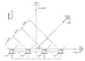
도 1은 본 발명의 일 실시예에 따른 음원 신호 처리 장치의 구성도로서, 음원 신호 처리 장치는 제1음원 검출부(110), 제2음원검출부(120), 음원 증폭부(130), 빔포밍부(140), 방향 입력부(150), 제어부(160), 출력부(170)를 포함한다.FIG. 1 is a block diagram of a sound source signal processing apparatus according to an embodiment of the present invention. The sound source signal processing apparatus includes a first sound
제1음원 검출부(110)는 단말기나 회의실과 같은 특정 공간 등 음원을 검출하고자 하는 영역에 고정 설치된다.The first sound
제1음원 검출부(110)는 마이크로폰 어레이로 이루어지고, 이 마이크로폰 어레이는 음원의 음파를 검출하고, 이 음파에 대응하는 전기 신호를 발생시킨다. 이 전기 신호를 음원 신호라 한다.The first sound
이 마이크로폰 어레이는 복수의 마이크로폰(ma1 내지 ma4)으로 이루어지고, 복수의 마이크로폰(ma1 내지 ma4)은 일직선 상에 서로 등간격 또는 비 등간격으로 마련된다. 이때 서로 인접한 마이크로폰 간의 간격은 미리 저장되어 있다.The microphone array is composed of a plurality of microphones ma1 to ma4, and the plurality of microphones ma1 to ma4 are arranged on a straight line at regular intervals or at equal intervals. At this time, intervals between adjacent microphones are stored in advance.
여기서 마이크로폰 어레이는 적어도 하나의 마이크로폰으로 이루어지는 것도 가능하다.Here, the microphone array may be composed of at least one microphone.
제2음원검출부(120)는 제1음원검출부(110)와 분리되어 서로 다른 위치에 설치된 것으로, 제2음원 검출부(120)는 제1음원 검출부(110)와 같은 영역에 고정 설치되되, 제1음원 검출부(110)와 이격 설치된다. 이때 제2음원 검출부(120)와 제1음원 검출부(110)의 상대적 위치 정보는 미리 정해져 저장 되어 있다.The second sound
여기서 제2음원 검출부(120)와 제1음원 검출부(110)의 상대적 위치 정보는 제2음원 검출부(120)와 제1음원 검출부(110)의 어느 한 점 사이의 상대적 거리 및 각도이다. 제1음원 검출부(110)의 어느 한 점은 제1 음원 검출부(110)의 일직선 상의 중심 점을 이용하는 것도 가능하다.The relative position information between the second sound
제2음원 검출부(120)는 적어도 하나의 마이크로폰(ms)으로 이루어지고, 이 마이크로폰은 음원의 음파를 검출하고, 이 음파에 대응하는 전기 신호를 발생시킨다. 이 전기 신호를 음원 신호라 한다.The second sound
음원 증폭부(130)는 복수개로 이루어진다. 이러한 음원 증폭부(130)는 제1음원 검출부(110)의 복수 마이크로폰(ma1 내지 ma4)에 각각 연결된 제1증폭부(131), 제2증폭부(132), 제3증폭부(133), 제4증폭부(134) 및 제2음원 검출부(120)의 마이크로폰(ms)에 연결된 제5증폭부(135)로 이루어진다.The sound
음원 증폭부(130)의 제1증폭부(131), 제2증폭부(132), 제3증폭부(133), 제4증폭부(134)는 제1음원 검출부(110)의 복수 마이크로폰(ma1 내지 ma4)으로부터 각각 전송된 음원 신호를 증폭시키고, 제5증폭부(135)는 제2음원 검출부(120)의 마이크로폰(ms)으로부터 전송된 음원 신호를 증폭시킨다.The
빔포밍부(140)는 제1음원 검출부(110) 및 제2음원 검출부(120)의 각 마이크로폰의 가중치를 변화시켜 음원 신호를 빔포밍함으로써 목표 방향에 존재하는 음원 신호만을 선택적으로 출력하고 나머지 방향에 존재하는 음원 신호는 제거한다.The
이러한 빔포밍부(140)는 음원 증폭부(130)로부터 전송된 각 음원 신호(Xn(t))를 저장하는 복수 개의 버퍼부와, 복수 개의 버퍼부로부터 음원 신호(Xn(t))를 전송받아 각 마이크로폰별로 주파수 변환(FFT)을 수행하여 주파수별로 신호를 분해하는 복수 개의 주파수 변환부(FFT)와, 복수 개의 주파수 변환부에서 주파수 변환된 신호를 수신하여 각각의 주파수에 해당하는 가중치를 반영한 후 신호를 합산하는 연산부와, 연산부로부터 신호를 수신받아 역 주파수 변환을 수행하는 역 주파수 변환부를 포함한다.The
만약 사용자로부터 어느 하나의 방향, 즉 빔포밍 방향이 입력된 경우, 빔포밍부(140)는 입력된 방향으로부터 검출되는 음원 신호에 시간차를 보상한 후 주파수 변환을 수행한다.If any direction from the user, that is, the beam forming direction, is input, the
빔포밍부(140)는 음성 신호가 존재하는 방향의 음원 신호만을 선택적으로 출력하고 음성 신호가 존재하지 않는 방향의 음원 신호는 제거하는 것도 가능하다.The
여기서 음성신호는 광대역 신호로, 빔포밍부(140)는 각각의 마이크로폰별로 일정 시간 음원 신호를 저장한 후 주파수 변환을 수행하고, 각각의 주파수 별로 협대역 빔포밍을 수행한 후 역 주파수 변환을 수행하여 빔포밍을 수행하게 된다. 따라서, 음원의 방향성을 이용하여 음성 신호가 포함된 음원의 방향과 다른 방향에서 검출되는 잡음을 제거할 수 있다.Here, the voice signal is a wideband signal, the
즉, 빔포밍부(140)는 제1음원 검출부(110) 및 제2음원검출부(120)의 마이크로폰을 통해 검출된 음원 신호 중 음성 신호가 존재하는 방향(또는 사용자로부터 입력된 방향)의 음원 신호만을 선택하여 출력하고 나머지 방향의 음원 시호는 제거한다.That is, the
이러한 빔포밍부(140)를 추후 도 2a 내지 도 2c를 참조하여 설명한다.The
방향 입력부(150)는 사용자로부터 어느 하나의 방향을 입력받고, 입력된 방향의 정보를 제어부(160)에 전송한다. 여기서 어느 하나의 방향은 빔포밍 시 지향하고자 하는 방향이다.The
제어부(160)는 제1음원 검출부(110)에서 검출된 음원에 특정 신호가 존재하는지 판단하고, 특정 신호가 존재한다고 판단되면 빔포머부(140)의 구동을 제어한다.The
여기서 특정 신호는 음성 신호인 것이 가능하다. 즉 음성 신호를 판단하는 것은, 사람이 귀로 들을 수 있는 주파수 범위 20 내지 20000Hz의 음압레벨 0 내지 130dB인 사운드 신호를 판단하는 것이다.Here, it is possible that the specific signal is a voice signal. That is, judging a voice signal is to judge a sound signal having a sound pressure level of 0 to 130 dB in a frequency range of 20 to 20,000 Hz in which a person can listen to the ear.
제어부(160)는 방향 입력부(150)를 통해 어느 하나의 방향 정보가 입력되면, 입력된 방향 정보를 빔포밍부(140)에 전송한다. 이로써 사용자에 의해 입력된 어느 하나의 방향에서 검출된 음원 신호만 필터링하는 것도 가능하다.When the direction information is input through the
제어부(160)는 빔포밍부(140)에서 빔포밍된 음원 신호가 출력부(170)를 통해 출력되도록 출력부(170)의 구동을 제어한다.The
출력부(170)는 제어부(160)의 제어 명령에 기초하여 역 주파수 변환에 대응하는 음원 신호를 진동판의 진동으로 바꾸어 공기에 음파를 출력한다.The
출력부(170)는 음성 신호를 출력하는 경우 역 주파수 변환에 대응하는 음성 신호를 진동판의 진동으로 바꾸어 공기에 소밀파를 발생시켜 음파를 출력한다.When outputting a voice signal, the
이러한 출력부(170)는 스피커로 이루어진다.The
도 2a 내지 도 2c는 본 발명의 일 실시예에 따른 음원 신호 처리 장치의 빔포밍 예시도이다.2A to 2C are diagrams illustrating examples of beamforming of a sound source signal processing apparatus according to an embodiment of the present invention.
도 2a에 도시된 바와 같이, 등 간격을 이루는 복수의 마이크로폰(ma1 내지 ma4)을 가지는 선형 마이크로폰 어레이를 가지는 제1음원 검출부(110)와, 선형 마이크로폰 어레이(ma1 내지 ma4)와 이격 설치된 적어도 하나의 마이크로폰(ms, 싱글 마이크로폰이라 함)을 가지는 제2음원 검출부(120)가 마련된다.A first sound
음원이 마이크로폰 어레이의 크기에 비해 먼 거리에서 발생한다고 가정하면 마이크로폰 어레이의 각 마이크로폰(ma1 내지 ma4)에 도달하는 신호는 평면파(planar wave)가 된다.Assuming that the sound source occurs at a distance greater than the size of the microphone array, the signal reaching each microphone (ma1 to ma4) of the microphone array becomes a planar wave.
이 평면파의 음원 신호가 마이크로폰 어레이의 각 마이크로폰(ma1 내지 ma4) 및 싱글 마이크로폰(ms)에 도달하는 신호는 마이크로폰의 위치에 따라 시간 지연만 다른 신호들이 된다.The signals that the sound source signals of the plane waves arrive at the respective microphones (ma1 to ma4) and the single microphone (ms) of the microphone array are signals having different time delays depending on the positions of the microphones.
도 2a에 도시된 바와 같이, 서로 인접한 마이크로폰 사이의 간격을 d, 음원 신호의 속도를 c, 음원의 검출 방향이 마이크 어레이에 대해 θ방향이라 하면, 서로 인접한 마이크로폰 사이의 음원 신호는
기준이 되는 마이크로폰(여기서는 첫 번째 마이크로폰(ma1)으로 함)의 음원 신호를 x0, 첫 번째 마이크로폰(ma1)에 음원 신호가 도달한 시간을 t라고 했을 때 마이크로폰 간 도달 시간의 차를 보상해주면 음원 신호(xn(t))의 출력은 다음과 같다.When said sound source signal from the microphone (here, the first microphone (ma1)) as a reference x0, for the first time that the sound signal reaches the second microphone (ma1) t haejumyeon compensate for the difference in arrival time between the microphone sound source The output of the signal xn (t) is as follows.

다음, 마이크로폰 어레이의 각 마이크로폰별 음원 신호(xn(t))와 각 마이크로폰별 가중치(w)를 반영하여 빔포밍한 결과는 다음과 같다.Next, the result of the beamforming reflecting the sound source signal xn (t) of each microphone of the microphone array and the weight (w) of each microphone is as follows.

이는 딜레이 앤 섬 빔포머(Delay-and-Sum Beamformer)를 이용한 것이다.It uses a delay-and-sum beamformer.
이에 대한 주파수 변환을 수행하면 다음과 같다.The frequency conversion is performed as follows.

따라서 빔포밍에 대한 주파수 응답은 다음과 같다.Therefore, the frequency response for beamforming is as follows.

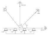
도 2b에 도시된 바와 같이, 제1음원 검출부(110)의 마이크로폰 어레이의 중심과 제2음원 검출부(120)의 싱글 마이크로폰 사이의 거리를 l, 각도를 Ω, 음원 신호의 속도를 c, 음원의 검출 방향이 마이크 어레이에 대해 θ방향이라 하면, 마이크로폰 어레이의 중심에 비해 싱글 마이크로폰(ms)은
기준이 되는 마이크로폰(여기서는 첫 번째 마이크로폰(ma1)으로 함)의 음원 신호를 x0, 첫 번째 마이크로폰(ma1)에 음원 신호가 도달한 시간을 t라고 했을 때 마이크로폰 간 도달 시간의 차를 보상해주면 싱글 마이크로폰(ms)의 음원 신호(xs(t))의 출력은 다음과 같다.When said sound source signal from the microphone (here, the first microphone (ma1)) as a reference x0, for the first time that the sound signal reaches the second microphone (ma1) t haejumyeon compensate for the difference in arrival time between the microphone single The output of the sound source signal xs (t) of the microphone ms is as follows.

다음, 싱글 마이크로폰(ms)의 음원 신호(xs(t))와 싱글 마이크로폰(ms)의 가중치(w')를 반영하여 빔포밍한 결과는 다음과 같다.Next, the result of beamforming reflecting the weight (w ') of the single microphone (ms) and the excitation signal xs (t) of the single microphone ms is as follows.

이에 대한 주파수 변환을 수행하면 다음과 같다.The frequency conversion is performed as follows.

따라서 빔포밍에 대한 주파수 응답은 다음과 같다.Therefore, the frequency response for beamforming is as follows.

즉, 제1음원 검출부(110)의 마이크로폰 어레이와 제2음원 검출부(120)의 싱글 마이크로폰의 음원 신호에 대한 주파수 응답은 다음과 같다.That is, the frequency response of the sound source signal of the microphone array of the first sound


즉, 음원 처리 장치는 빔포밍부(140)의 빔포밍에 의해 H(f)에 대응하는 신호를 출력하게 된다.In other words, the sound source processing apparatus outputs a signal corresponding to H (f) by beamforming of the
도 2c에 도시된 바와 같이, 사용자로부터 어느 하나의 방향(φ)에서 발생된 음원 신호만을 필터링하게 설계되었다면 각 마이크로폰에 들어오는 음원 신호에 각각

다음, 마이크로폰 어레이의 마이크로폰(ma1 내지 ma4)별 음원 신호(xn(t))와 각 마이크로폰별 가중치(w)를 반영하여 빔포밍한 결과는 다음과 같다.Next, the result of the beamforming reflecting the sound source signal xn (t) for each microphone (ma1 to ma4) of the microphone array and the weight (w) for each microphone is as follows.

이에 대한 주파수 변환을 수행하면 다음과 같다.The frequency conversion is performed as follows.

따라서 빔포밍에 대한 주파수 응답은 다음과 같다.Therefore, the frequency response for beamforming is as follows.

제1음원 검출부(110)의 마이크로폰 어레이와 제2음원 검출부(120)의 싱글 마이크로폰(ms)의 음원 신호를 처리하여 얻은 주파수 응답은 다음과 같다.The frequency response obtained by processing the sound source signals of the microphone array of the first sound


즉, 음원 처리 장치는 빔포밍부(140)의 빔포밍에 의해 H(f)에 대응하는 신호를 출력하게 된다.In other words, the sound source processing apparatus outputs a signal corresponding to H (f) by beamforming of the
이와 같이 N개의 마이크로폰로 이루어지는 마이크로폰 어레이에 이격 설치된 싱글 마이크로폰을 더 추가함으로써, 전체적인 마이크로폰의 크기를 늘릴 수 있어 분해 성능을 향상시킬 수 있고, 또한 저주파 대역의 신호의 빔포밍 효과를 향상시킬 수 있다.By additionally providing a single microphone spaced apart from the microphone array composed of N microphones, it is possible to increase the size of the entire microphone, thereby improving the degradation performance and improving the beam forming effect of the low frequency band signal.
특히 음성 신호의 경우 1,000Hz 이하에서 효과적인 빔포밍을 수행할 수 있다.In particular, in the case of a voice signal, efficient beamforming can be performed at 1,000 Hz or less.
여기서 분해성능은 마이크로폰 어레이의 크기와 주파수에 비례하기 때문이다.This is because the decomposition performance is proportional to the size and frequency of the microphone array.
이로 인해 마이크로폰 어레이 내의 마이크로폰의 수를 늘리거나 마이크로폰 간 거리를 넓히지 않고도, 마이크로폰의 크기를 늘일 수 있어 마이크로폰 어레이의 제조 단가를 낮출 수 있고 마이크로폰 어레이의 설치에 따른 공간을 효율적으로 이용할 수 있다.This can increase the size of the microphone without increasing the number of the microphones in the microphone array or widening the distance between the microphones, thereby reducing the manufacturing cost of the microphone array and efficiently utilizing the space for installation of the microphone array.
도 3은 본 발명의 일 실시예에 따른 음원 신호 처리 장치의 제어 순서도이다.3 is a flowchart illustrating a control procedure of a sound source signal processing apparatus according to an embodiment of the present invention.
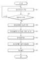
제1음원 검출부(110)의 마이크로폰 어레이 및 제2음원 검출부(120)의 마이크로폰(ms)을 이용하여 음원을 검출(201)하고, 각 마이크로폰(ma1 내지 ma4, ms)을 통해 검출된 음원 신호를 각각의 음원 증폭부(130: 131 내지 135)에서 증폭하고, 증폭된 아날로그 신호인 음원 신호를 디지털 신호로 변환(202)한다.The sound source is detected 201 using the microphone array of the first sound
다음 음원 신호 처리 장치는 미리 정해진 제1음원 검출부(110)의 마이크로폰 어레이 및 제2음원 검출부(120)의 마이크로폰(ms) 사이의 상대적 위치 정보인 거리(l)와 각도(Ω), 제1음원 검출부(110)의 마이크로폰 어레이를 이루는 마이크로폰(ma1 내지 ma4) 간의 미리 정해진 거리(d) 정보를 이용하여 빔포밍을 수행한다.The next sound source signal processing apparatus includes a distance l and an angle Ω which are relative positional information between a predetermined microphone array of the first sound
여기서 빔포밍 수행을 좀 더 구체적으로 설명하면 다음과 같다.Here, the beamforming operation will be described in more detail as follows.
음원 신호 처리 장치는 각 마이크로폰(ma1 내지 ma4, ms)에서 검출된 음원 신호를 일정기간 저장하였다가 마이크로폰(ma1 내지 ma4, ms)별 음원 신호에 가중치를 반영하여 합산하고, 합산된 신호를 주파수 변환(FFT)을 수행(203)한다.The sound source signal processing apparatus stores the sound source signals detected by the microphones ma1 to ma4 and ms for a predetermined period of time, reflects the weights to the sound source signals of the microphones ma1 to ma4 and ms, (FFT) is performed (203).
다음 음원 신호 처리 장치는 주파수 변환된 신호를 주파수별로 분해한 후 역 주파수 변환을 수행(204)한다.The next sound source signal processor decomposes the frequency-converted signal by frequency and performs an inverse frequency conversion (204).
이때 음원 신호 처리 장치는 음원 신호를 각각의 주파수별로 나누어 가중치를 적용한 후 다시 합산하면 음성 신호의 주파수만으로 독립인 빔을 만들 수 있다.In this case, the sound source signal processing apparatus can divide the sound source signal into individual frequencies, apply the weights, and then add the sound signals to generate independent beams only at the frequency of the sound signal.
다음, 음원 신호 처리 장치는 디지털 신호인 역 주파수 변환에 대응하는 신호를 아날로그 신호로 변환한 후 아날로그 신호로 변환된 음원을 출력(205)한다.Next, the sound source signal processing apparatus converts a signal corresponding to the reverse frequency conversion, which is a digital signal, into an analog signal, and outputs (205) the sound source converted into the analog signal.
도 4a 내지 4c는 본 발명의 일 실시예에 따른 음원 신호 처리 장치의 빔패턴 예시도이다.4A to 4C are diagrams illustrating exemplary beam patterns of a sound source signal processing apparatus according to an exemplary embodiment of the present invention.
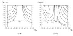
도 4a의 좌측은 종래 음원 신호 처리 장치의 빔포밍 시 주파수 8000Hz 이내의 빔패턴이고, 우측은 본 발명의 실시예에 따른 음원 신호 처리 장치의 빔포밍 시 주파수 8000Hz 이내의 빔패턴이다.The left side of FIG. 4A is a beam pattern within a frequency of 8000 Hz at the time of beamforming of a conventional tone signal processing apparatus, and the right side is a beam pattern within a frequency of 8000 Hz at the time of beamforming of a tone signal processing apparatus according to an embodiment of the present invention.
도 4b의 좌측 빔패턴과 우측 빔패턴은 도 4a의 좌측 빔패턴과 우측 빔패턴 중 저주파인 주파수 1000Hz 이내의 빔패턴을 확대한 것이다.The left beam pattern and the right beam pattern in FIG. 4B are enlarged beam patterns within a frequency of 1000 Hz which is a low frequency of the left and right beam patterns in FIG. 4A.
도 4c의 좌측은 종래 음원 신호 처리 장치의 빔포밍 시 주파수 1000Hz 이내의 빔패턴이고, 우측은 본 발명의 실시예에 따른 음원 신호 처리 장치의 빔포밍 시 주파수 1000Hz 이내의 빔패턴이다. 도 4c는 사용자로부터 입력된 빔포밍 지향 방향이 각도 60ㅀ인 음원 신호의 빔패턴이다.The left side of FIG. 4C is a beam pattern within a frequency of 1000 Hz at the time of beam forming of the conventional tone signal processing apparatus, and the right side is a beam pattern within a frequency of 1000 Hz at the time of beam forming of the tone signal processing apparatus according to the embodiment of the present invention. 4C is a beam pattern of a sound source signal having an angle of 60 [mu] in the direction of beam-forming input from the user.
도 4a 내지 도 4c의 좌우 빔패턴을 살펴보면, 좌측에 도시된 종래 빔패턴에 비해 우측에 도시된 본 발명의 실시예에 따른 빔패턴의 빔폭(BW: Beam Width)이 훨씬 좁은 것을 알 수 있다.4A to 4C, the beam width (BW) of the beam pattern according to the embodiment of the present invention is much narrower than the conventional beam pattern shown on the left side.
특히 도 4b에 도시된 바와 같이 1Khz 이하의 저주파 대역에서의 빔패턴에서 빔폭(BW: Beam Width)이 더욱 좁아짐이 두드러진 것을 알 수 있다.In particular, as shown in FIG. 4B, it can be seen that the beam width (BW) is further narrowed in the beam pattern in the low frequency band of 1 KHz or less.
또한 도 4c에 도시된 바와 같이 양끝 단에서 빔폭(BW: Beam Width)이 종래보다 본 발명의 실시예에서 더 좁음을 알 수 있다.Also, as shown in FIG. 4C, the beam width (BW) at both ends is narrower in the embodiment of the present invention than in the prior art.
이에 따라 공간필터의 분해성능이 뛰어나고 그 만큼 지향성 잡음과 음성 신호를 잘 분리해 낼 수가 있다. 여기서 빔패턴의 빔폭이 좁은 만큼 공간필터의 분해성능이 뛰어나기 때문이다.Accordingly, the spatial filter is superior in the decomposition performance and the directional noise and the voice signal can be separated well. This is because the spatial resolution of the spatial filter is improved as the beam width of the beam pattern is narrow.
즉 음원 신호 처리 장치는 저주파대역에서 분해성능을 효율적으로 유지할 수 있고, 또한 중요한 저주파 대역의 신호를 특별한 후처리 필요없이 유지시켜줄 수 있다.That is, the sound source signal processing apparatus can efficiently maintain the decomposition performance in a low frequency band, and can also keep important low frequency band signals without special post-processing.
도 5는 본 발명의 다른 실시예에 따른 음원 신호 처리 장치의 구성도이고, 도 6은 본 발명의 다른 실시예에 따른 음원 신호 처리 장치의 빔포밍 예시도이다.FIG. 5 is a block diagram of a sound source signal processing apparatus according to another embodiment of the present invention, and FIG. 6 is an illustration of an example of beam forming of a sound source signal processing apparatus according to another embodiment of the present invention.
도 5에 도시된 바와 같이 음원 신호 처리 장치는 제1음원 검출부(310), 제2음원검출부(320), 음원 증폭부(330), 빔포밍부(340), 방향 입력부(350), 제어부(360), 출력부(370), 위치검출부(380)를 포함한다.5, the sound source signal processing apparatus includes a first sound
여기서 음원 증폭부(330), 빔포밍부(340), 방향 입력부(350), 출력부(370)는 도 1에 도시된 음원 증폭부(130), 빔포밍부(140), 방향 입력부(150), 출력부(170)의 구성과 동일하여 그 설명을 생략한다.The sound
제1음원 검출부(310)는 단말기나 회의실과 같은 특정 공간 등 음원을 검출하고자 하는 영역에 설치된다.The first sound
제1음원 검출부(310)는 마이크로폰 어레이로 이루어지고, 이 마이크로폰 어레이는 음원의 음파를 검출하고, 이 음파에 대응하는 전기 신호를 발생시킨다. 이 전기 신호를 음원 신호라 한다.The first sound
이 마이크로폰 어레이는 복수의 마이크로폰(ma1 내지 ma4)으로 이루어지고, 복수의 마이크로폰(ma1 내지 ma4)은 일직선 상에 서로 등간격 또는 비 등간격으로 마련된다. 이때 서로 인접한 마이크로폰 간의 간격은 미리 저장되어 있다.The microphone array is composed of a plurality of microphones ma1 to ma4, and the plurality of microphones ma1 to ma4 are arranged on a straight line at regular intervals or at equal intervals. At this time, intervals between adjacent microphones are stored in advance.
여기서 마이크로폰 어레이는 적어도 하나의 마이크로폰으로 이루어지는 것도 가능하다.Here, the microphone array may be composed of at least one microphone.
제2음원검출부(320)는 제1음원검출부(310)와 분리되어 서로 다른 위치에 설치된 것으로, 제2음원 검출부(320)는 제1음원 검출부(310)와 같은 영역에 설치되되, 제1음원 검출부(310)와 이격 설치되고, 또한 이동 가능하게 설치된다.The second sound
여기서 제2음원 검출부(320)와 제1음원 검출부(310)의 상대적 위치 정보는 제2음원 검출부(320)와 제1음원 검출부(310)의 어느 한 점 사이의 상대적 거리 및 각도이다. 제1음원 검출부(310)의 어느 한 점은 제1 음원 검출부(310)의 일직선 상의 중심 점을 이용하는 것이 가능하다.The relative positional information between the second sound
제2음원 검출부(320)는 적어도 하나의 마이크로폰(ms)으로 이루어지고, 이 마이크로폰(ms)은 음원의 음파를 검출하고, 이 음파에 대응하는 전기 신호를 발생시킨다. 이 전기 신호를 음원 신호라 한다.The second sound
제어부(360)는 적어도 하나의 마이크로폰(ma1 내지 ma4, ms)으로부터 검출된 음원 신호에 음성 신호가 존재하는지 판단하고, 음성 신호가 존재한다고 판단되면 위치검출부(380)의 송신부(381)가 구동되도록 송신부(381)를 제어하고, 위치검출부(380)의 수신부(382)로부터 수신된 신호에 기초하여 제1음원 검출부(310)의 마이크로폰 어레이와 제2음원 검출부(320)의 마이크로폰 사이의 상대적 위치를 판단한다.The
여기서 음성 신호의 존재를 판단하는 것은, 검출된 음원 신호에 가청 주파수 20 내지 20000Hz 가 포함되었는지 판단하는 것이다.The determination of the presence of the speech signal is to determine whether the detected sound source signal includes an audible frequency of 20 to 20000 Hz.
아울러 제1음원 검출부(310)의 마이크로폰 어레이와 제2음원 검출부(320)의 마이크로폰 사이의 상대적 위치는, 제1음원 검출부(310)의 마이크로폰 어레이의 중심과 제2음원 검출부(320)의 마이크로폰 사이의 상대적 거리(l) 및 각도(Ω)이다.The relative position between the microphone array of the first sound
여기서 기준 음압은 사람이 들을 수 있는 대략 0 내지 130dB의 음압이다.Here, the reference sound pressure is a sound pressure of about 0 to 130 dB which can be heard by a person.
아울러 음성 신호 이외에도 사용자로부터 입력된 특정 신호를 검출하여 빔포밍을 제어하는 것도 가능하다.It is also possible to control a beamforming by detecting a specific signal inputted from a user in addition to a voice signal.
제어부(360)는 음성 신호가 존재하면 제1음원 검출부(310)의 마이크로폰 어레이와 제2음원 검출부(320)의 마이크로폰(ms) 사이의 상대적 위치 정보를 빔포밍부(340)에 전송하고, 빔포머부(340)의 구동을 제어함으로써 제1음원 검출부(310)의 마이크로폰 어레이와 제2음원 검출부(320)의 마이크로폰 사이의 상대적 위치에 기초하여 음성 신호의 빔포밍이 수행되도록 한다.The
제어부(360)는 음압검출부(미도시)의 구동을 제어하여 음압이 검출되도록 하고, 음압 검출부로부터 검출된 음압레벨 신호가 전송되면 검출된 음압과 기준 음압레벨을 비교하여 검출된 음압레벨이 기준 음압레벨 이상이면 빔포밍부(340)의 구동을 제어하는 것도 가능하다.The
제어부(360)는 방향 입력부(350)를 통해 어느 하나의 방향 정보가 입력되면, 입력된 방향의 정보를 빔포밍부(140)에 전송한다. 이로써 사용자에 의해 입력된 어느 하나의 방향에서 검출되는 음성 신호만 필터링하는 것도 가능하다.The
제어부(360)는 빔포밍부(340)에서 빔포밍된 음성 신호가 출력부(370)를 통해 출력되도록 출력부(370)의 구동을 제어한다.The
위치 검출부(380)는 송신부(381)와 수신부(382)로 이루어진다.The
도 6에 도시된 바와 같이 위치 검출부(380)의 송신부(381)는 제2음원 검출부(320)의 마이크로폰(ms)과 인접하게 설치되고, 위치 검출부(380)의 수신부(382)는 제1음원 검출부(310)의 마이크로폰 어레이(ma1 내지 ma4)와 인접하게 설치된다.6, the transmitting
아울러 위치 검출부(380)의 송신부(381)는 제1음원 검출부(310)의 마이크로폰 어레이와 인접하게 설치되고, 위치 검출부(380)의 수신부(382)는 제2음원 검출부(320)의 마이크로폰(ms)과 인접하게 설치되는 것도 가능하다.The transmitting
이때 위치 검출부(380)의 수신부(382)는 제1음원 검출부(310)의 마이크로폰 어레이의 일직선 상의 중심에 설치하는 것도 가능하다.At this time, the receiving
위치 검출부(380)의 송신부(381)는 제어부(360)의 명령에 대응하여 위치 신호를 송신하고, 위치 검출부(380)의 수신부(382)는 송신부(381)에서 송신된 위치 신호를 수신하여 제어부(360)에 전송한다.The
여기서 위치 검출부(380)의 송신부(381)는 초음파 발진부, 송신부(382)는 초음파 수신부로 이루어지는 것이 가능하고, 이 경우 제어부(360)는 초음파가 도달된 시간에 기초하여 제1, 2 음원 검출부(310, 320) 간의 상대적 위치를 판단한다.Here, the transmitting
또한 위치 검출부(380)의 송신부(381)는 알에프(RF: Radio Frequency) 발진부, 송신부(382)는 알에프(RF) 수신부로 이루어지는 것이 가능하고, 이 경우 제어부(360)는 알에프(RF) 신호가 도달된 시간에 기초하여 제1, 2 음원 검출부(310, 320) 간의 상대적 위치를 판단한다.The
아울러 위치 검출부(380)의 송신부(381)는 적외선 방출부, 송신부(382)는 적외선 수신부로 이루어지는 것이 가능하고, 이 경우 제어부(360)는 광량에 기초하여 제1, 2 음원 검출부(310, 320) 간의 상대적 위치를 판단하는 것도 가능하다.In this case, the
도 7은 본 발명의 다른 실시예에 따른 음원 신호 처리 장치의 제어 순서도이다. 여기서 음성 신호를 빔포밍하여 출력하는 것을 예를 들어 설명한다.7 is a control flowchart of a sound source signal processing apparatus according to another embodiment of the present invention. Here, a description will be given of an example in which a voice signal is beamformed and output.
음원 신호 처리 장치는 대기상태(Idle)를 유지하면서 음원 검출 영역에서 발생하는 음원 신호의 음압 레벨을 검출하고, 검출된 음압 레벨이 기준 음압 레벨 이상인지 판단함으로써 음원 검출 영역의 음원 신호에 음성 신호가 존재하는지 모니터링(401)한다.The sound source signal processing apparatus detects the sound pressure level of the sound source signal generated in the sound source detection area while keeping the standby state Idle and judges whether the detected sound pressure level is equal to or higher than the reference sound pressure level, (401).
여기서 기준 음압 레벨은 음성인지 판단하기 위한 음압 레벨(Sound Pressure Level, SPL)이다.Here, the reference sound pressure level is a sound pressure level (SPL) for determining whether sound is sound.
이때 음원 신호 처리 장치는 기준 음압 레벨 미만의 음압 레벨을 가진 음원이 검출되면 음성 신호가 존재하지 않는다고 판단하고, 기준 음압 레벨 이상의 음압레벨을 가진 음원이 검출되면 음성 신호가 존재(402)한다고 판단한다.At this time, if the sound source having the sound pressure level lower than the reference sound pressure level is detected, the sound source signal processing apparatus determines that the sound signal is not present. If the sound source having the sound pressure level higher than the reference sound pressure level is detected, .
아울러 음성 신호의 존재 여부를 판단하는 것은, 음원 신호의 주파수에 기초하여 판단하는 것도 가능하다.It is also possible to determine whether or not the voice signal is present based on the frequency of the sound source signal.
다음 음성 신호가 존재하면 제2음원 검출부(320)의 마이크로폰(ms)에 인접 설치된 위치 검출부(380)의 송신부(381)를 구동(403)시켜 위치 신호를 송신한다.If the next voice signal is present, the
다음, 제1음원 검출부(310)의 마이크로폰 어레이의 중심에 인접 설치된 위치 검출부(380)의 수신부(382)에서 송신부(381)의 위치 신호가 수신(404)되면 수신된 위치 신호를 제어부(360)에 전송한다.Next, when the position signal of the transmitting
여기서 신호는 RF 또는 초음파 중 어느 하나이다. 아울러 신호는 적외선인 것도 가능하다.Where the signal is either RF or ultrasonic. It is also possible that the signal is infrared.
다음 음원 신호 처리 장치의 제어부(360)는 수신된 신호에 기초하여 제1음원 검출부(310)의 마이크로폰 어레이의 중심과 제2음원 검출부(320)의 마이크로폰(ms) 사이의 상대적 위치 정보인 거리(l)와 각도(Ω)를 획득(405)하고 획득된 위치 정보를 빔포밍부(340)에 전송한다.The
다음, 음원 신호 처리 장치는 제1음원 검출부(310)의 마이크로폰 어레이 및 제2음원 검출부(320)의 마이크로폰(ms)을 이용하여 음원 신호를 검출하고, 검출된 음원을 각각의 음원 증폭부(330: 331 내지 335)에서 증폭하고, 증폭된 아날로그 신호의 음원 신호를 디지털 신호로 변환한다.Next, the sound source signal processing apparatus detects a sound source signal using the microphone array of the first sound
다음 음원 신호 처리 장치는 제1음원 검출부(310)의 마이크로폰 어레이 및 제2음원 검출부(320)의 마이크로폰(ms) 사이의 상대적 위치 정보인 거리(l)와 각도(Ω), 제1음원 검출부(110)의 마이크로폰 어레이를 이루는 마이크로폰(ma1 내지 ma4) 간의 미리 정해진 거리(d) 정보를 이용하여 빔포밍을 수행(406)한다.The next sound source signal processing apparatus includes a distance l and an angle Ω which are relative positional information between the microphone array of the first sound
다음 음원 신호 처리 장치는 빔포밍된 음원 신호 중 음성 신호를 강조하여 출력부(370)를 통해 출력(407)한다.Next, the sound source signal processing apparatus emphasizes the voice signal among the beam-formed sound source signals and outputs (407) through the
그리고 음원이 발생하는 동안 제2음원 검출부(320)의 위치가 변경될 수 있기 때문에 일정 주기로 위치 검출부(380)의 송신부(381)와 수신부(382)의 동작을 제어하여 제2음원 검출부(320)와 제1음원 검출부(310)의 위치 정보를 획득하고, 획득된 정보에 기초하여 빔포밍을 수행한다.Since the position of the second
아울러 위치 검출부(380)의 수신부(382)에 수신된 신호로부터 제2음원 검출부(320)의 위치를 알 수 없는 경우에는 제1음원 검출부(310)의 마이크로폰 어레이만의 독립적인 빔포밍을 수행하도록 한다.If the position of the second sound
110, 310: 제1음원 검출부120, 320: 제2음원 검출부
130, 330: 음원 증폭부140, 340: 빔포밍부
150: 350: 방향 입력부160, 360: 제어부
170, 370: 출력부380: 위치 검출부
381: 송신부382: 수신부110, 310: first sound
130, 330: Sound
150: 350:
170, 370: output unit 380: position detector
381: transmitting unit 382:
Claims (20)
Translated fromKorean상기 음원 신호를 검출하는 하나의 마이크로폰을 가지는 제2음원 검출부; 및
상기 제1음원 검출부와 상기 제2음원 검출부의 상기 하나의 마이크로폰 사이의 상대적인 위치에 기초하여 상기 제1음원 검출부 및 상기 제2음원 검출부의 상기 하나의 마이크로폰에서 검출된 상기 음원 신호를 빔포밍하는 빔포밍부를 포함하되,
상기 상대적인 위치는 상기 제1음원 검출부의 중심과 상기 제2음원 검출부의 상기 하나의 마이크로폰 사이의 거리 및 각도인 음원 신호 처리 장치.A first sound source detection unit having at least one microphone for detecting a sound source signal;
A second sound source detection unit having a microphone for detecting the sound source signal; And
And a second sound source detection unit for detecting the sound source signal detected by the first sound source detection unit and the second sound source detection unit based on a relative position between the first sound source detection unit and the one microphone of the second sound source detection unit. Forming portion,
Wherein the relative position is a distance and an angle between the center of the first sound source detection unit and the one microphone of the second sound source detection unit.
상기 제1음원 검출부와 상기 제2음원 검출부의 상기 하나의 마이크로폰 사이의 상기 상대적인 위치는 미리 정해진 음원 신호 처리 장치.The method according to claim 1,
Wherein the relative position between the first sound source detecting unit and the one microphone of the second sound source detecting unit is predetermined.
상기 제1음원 검출부와 상기 제2음원 검출부의 상기 하나의 마이크로폰에 마련되어 상기 제1음원 검출부와 상기 제2음원 검출부의 상기 하나의 마이크로폰 사이의 상기 상대적인 위치를 검출하는 위치 검출부를 더 포함하는 음원 신호 처리 장치.The method according to claim 1,
And a position detector for detecting the relative position between the first sound source detecting unit and the one microphone of the second sound source detecting unit, the position detecting unit being provided in the one microphone of the first sound source detecting unit and the second sound source detecting unit, Processing device.
알에프 송신부와, 알에프 수신부를 포함하는 음원 신호 처리 장치.5. The apparatus according to claim 4,
An RF transmitting unit, and an RF receiving unit.
초음파 송신부와 초음파 수신부를 포함하는 음원 신호 처리 장치.5. The apparatus according to claim 4,
A sound source signal processing apparatus comprising an ultrasonic transmission unit and an ultrasonic reception unit.
적외선 송신부와 적외선 수신부를 포함하는 음원 신호 처리 장치.5. The apparatus according to claim 4,
An audio signal processing apparatus including an infrared ray transmitting unit and an infrared ray receiving unit.
상기 음원 신호의 음압을 검출하는 음압 검출부; 및
상기 검출된 음원 신호의 음압 레벨과 기준 음압 레벨을 비교하여 상기 음원 신호 내에 음성 신호가 존재하는지 여부를 판단하고, 상기 음원 신호 내에 상기 음성 신호가 존재한다고 판단되면 상기 음원 신호의 빔포밍이 수행되도록 제어하는 제어부를 더 포함하는 음원 신호 처리 장치.The method according to claim 1,
A sound pressure detector for detecting the sound pressure of the sound source signal; And
And determining whether or not a voice signal exists in the sound source signal by comparing the sound pressure level of the detected sound source signal with a reference sound pressure level so that if the sound signal is present in the sound source signal, And a control unit for controlling the sound source signal processing unit.
제어부를 더 포함하고,
상기 제어부는 상기 빔포밍 수행 제어 시 상기 위치 검출부가 주기적으로 구동되도록 제어하여 상기 제1음원 검출부와 상기 제2음원 검출부의 상기 하나의 마이크로폰 사이의 상기 상대적인 위치를 획득하는 음원 신호 처리 장치.5. The method of claim 4,
Further comprising a control unit,
Wherein the controller controls the position detector to be periodically driven during the beamforming performance control to obtain the relative position between the one microphone of the first sound source detector and the one microphone of the second sound source detector.
사용자로부터 상기 빔포밍 시 방향 정보를 입력 받는 방향 입력부를 더 포함하고,
상기 빔포밍부는, 상기 사용자로부터 입력된 상기 방향 정보를 반영하여 상기 음원 신호를 빔포밍하는 음원 신호 처리 장치.The method according to claim 1,
Further comprising a direction input unit for receiving the direction information at the beam forming from a user,
Wherein the beamforming unit reflects the direction information input from the user to beamform the sound source signal.
상기 제1 음원 검출부와 상기 제2 음원 검출부의 상기 하나의 마이크로폰 사이의 상대적인 위치에 기초하여 상기 음원 신호를 빔포밍하되,
상기 상대적인 위치는 상기 제1음원 검출부의 중심과 상기 제2음원 검출부의 상기 하나의 마이크로폰 사이의 거리 및 각도인 음원 신호 처리 방법.Detecting a sound source signal at different positions through a first sound source detecting unit having at least one microphone and a second sound source detecting unit including one microphone;
Wherein the sound source signal is beamformed based on a relative position between the first sound source detecting unit and the one microphone of the second sound source detecting unit,
Wherein the relative position is a distance and an angle between a center of the first sound source detection unit and the one microphone of the second sound source detection unit.
상기 서로 다른 위치에서 검출된 각 음원 신호에 가중치를 반영하여 각각 주파수 변환하고;
상기 각각 주파수 변환된 신호를 합산하고;
상기 합산된 신호의 역 주파수 변환을 수행하는 것을 포함하는 음원 신호 처리 방법.13. The method of claim 12, wherein beamforming the excitation signal comprises:
Each of the sound source signals detected at the different positions is frequency-converted by reflecting a weight value;
Sum the frequency-converted signals;
And performing inverse frequency conversion of the summed signal.
상기 제1 음원 검출부와 상기 제2 음원 검출부의 상기 하나의 마이크로폰 사이의 상기 상대적인 위치는 미리 정해진 음원 신호 처리 방법.13. The method of claim 12,
Wherein the relative position between the first sound source detection unit and the one microphone of the second sound source detection unit is predetermined.
상기 음원 신호가 검출되면 상기 제2음원 검출부의 상기 하나의 마이크로폰에 인접하게 설치된 송신부를 통해 위치 신호를 송신하고;
상기 제1음원 검출부에 인접하게 설치된 수신부를 통해 상기 위치 신호를 수신하고;
상기 수신된 위치 신호에 기초하여 상기 서로 다른 위치에서 검출된 상기 음원 신호 간 상기 상대적인 위치를 획득하는 것을 더 포함하는 음원 신호 처리 방법.13. The method of claim 12,
When the sound source signal is detected, transmitting a position signal through a transmission unit provided adjacent to the one microphone of the second sound source detection unit;
Receiving the position signal via a receiving unit provided adjacent to the first sound source detecting unit;
And obtaining the relative position between the sound source signals detected at the different positions based on the received position signal.
상기 음원 신호가 검출되면 상기 제1음원 검출부에 인접하게 설치된 송신부를 통해 위치 신호를 송신하고;
상기 제2음원 검출부의 상기 하나의 마이크로폰에 인접하게 설치된 수신부를 통해 상기 위치 신호를 수신하고;
상기 수신된 위치 신호에 기초하여 상기 서로 다른 위치에서 검출된 상기 음원 신호 간 상기 상대적인 위치를 획득하는 것을 더 포함하는 음원 신호 처리 방법.13. The method of claim 12,
When the sound source signal is detected, transmitting a position signal through a transmission unit provided adjacent to the first sound source detection unit;
Receiving the position signal through a receiving unit provided adjacent to the one microphone of the second sound source detecting unit;
And obtaining the relative position between the sound source signals detected at the different positions based on the received position signal.
초음파 신호 또는 알에프 신호 중 어느 하나의 신호인 음원 신호 처리 방법.17. The method according to claim 15 or 16,
Wherein the signal is one of an ultrasonic signal and an RF signal.
사용자에 의해 입력된 방향 정보에 기초하여 상기 음원 신호를 빔포밍하는 음원 신호 처리 방법.13. The method of claim 12, wherein beamforming the excitation signal comprises:
A method of processing a sound source signal for beamforming the sound source signal based on direction information input by a user.
상기 음원 신호의 음압 레벨을 검출하고;
상기 검출된 음압 레벨과 기준 음압 레벨을 비교하고;
상기 검출된 음압 레벨이 상기 기준 음압 레벨 이상이면 상기 음원 신호 내에 음성 신호가 존재한다고 판단하고;
상기 음원 신호 내에 상기 음성 신호가 존재한다고 판단되면 상기 음원 신호를 빔포밍하는 것을 더 포함하는 음원 신호 처리 방법.13. The method of claim 12,
Detecting a sound pressure level of the sound source signal;
Comparing the detected sound pressure level with a reference sound pressure level;
Determining that a voice signal exists in the sound source signal if the detected sound pressure level is equal to or greater than the reference sound pressure level;
Further comprising: beamforming the sound source signal if it is determined that the sound signal exists in the sound source signal.
상기 음원 신호의 주파수를 확인하고;
상기 확인된 주파수에 기초하여 상기 음원 신호 내에 음성 신호가 존재하는지 여부를 판단하고;
상기 음원 신호 내에 상기 음성 신호가 존재한다고 판단되면 상기 음원 신호를 빔포밍하는 음원 신호 처리 방법.13. The method of claim 12, wherein beamforming the excitation signal comprises:
Identify the frequency of the source signal;
Determining whether a voice signal is present in the sound source signal based on the identified frequency;
Wherein the sound source signal is beamformed when it is determined that the sound signal exists in the sound source signal.
Priority Applications (2)
| Application Number | Priority Date | Filing Date | Title |
|---|---|---|---|
| KR1020100110838AKR101715779B1 (en) | 2010-11-09 | 2010-11-09 | Apparatus for sound source signal processing and method thereof |
| US13/275,801US9113242B2 (en) | 2010-11-09 | 2011-10-18 | Sound source signal processing apparatus and method |
Applications Claiming Priority (1)
| Application Number | Priority Date | Filing Date | Title |
|---|---|---|---|
| KR1020100110838AKR101715779B1 (en) | 2010-11-09 | 2010-11-09 | Apparatus for sound source signal processing and method thereof |
Publications (2)
| Publication Number | Publication Date |
|---|---|
| KR20120049534A KR20120049534A (en) | 2012-05-17 |
| KR101715779B1true KR101715779B1 (en) | 2017-03-13 |
Family
ID=46019647
Family Applications (1)
| Application Number | Title | Priority Date | Filing Date |
|---|---|---|---|
| KR1020100110838AActiveKR101715779B1 (en) | 2010-11-09 | 2010-11-09 | Apparatus for sound source signal processing and method thereof |
Country Status (2)
| Country | Link |
|---|---|
| US (1) | US9113242B2 (en) |
| KR (1) | KR101715779B1 (en) |
Families Citing this family (37)
| Publication number | Priority date | Publication date | Assignee | Title |
|---|---|---|---|---|
| US9078057B2 (en)* | 2012-11-01 | 2015-07-07 | Csr Technology Inc. | Adaptive microphone beamforming |
| KR102150013B1 (en) | 2013-06-11 | 2020-08-31 | 삼성전자주식회사 | Beamforming method and apparatus for sound signal |
| US9747917B2 (en) | 2013-06-14 | 2017-08-29 | GM Global Technology Operations LLC | Position directed acoustic array and beamforming methods |
| KR101682484B1 (en)* | 2013-08-20 | 2016-12-05 | (주)파워보이스 | Device and method for tracking location of sound source |
| WO2015159731A1 (en)* | 2014-04-16 | 2015-10-22 | ソニー株式会社 | Sound field reproduction apparatus, method and program |
| US10412208B1 (en)* | 2014-05-30 | 2019-09-10 | Apple Inc. | Notification systems for smart band and methods of operation |
| US9326060B2 (en)* | 2014-08-04 | 2016-04-26 | Apple Inc. | Beamforming in varying sound pressure level |
| WO2016114487A1 (en)* | 2015-01-13 | 2016-07-21 | 주식회사 씨케이머티리얼즈랩 | Haptic information provision device |
| US9554207B2 (en) | 2015-04-30 | 2017-01-24 | Shure Acquisition Holdings, Inc. | Offset cartridge microphones |
| US9565493B2 (en) | 2015-04-30 | 2017-02-07 | Shure Acquisition Holdings, Inc. | Array microphone system and method of assembling the same |
| GB2551780A (en)* | 2016-06-30 | 2018-01-03 | Nokia Technologies Oy | An apparatus, method and computer program for obtaining audio signals |
| US10367948B2 (en) | 2017-01-13 | 2019-07-30 | Shure Acquisition Holdings, Inc. | Post-mixing acoustic echo cancellation systems and methods |
| US10789949B2 (en)* | 2017-06-20 | 2020-09-29 | Bose Corporation | Audio device with wakeup word detection |
| US11150869B2 (en) | 2018-02-14 | 2021-10-19 | International Business Machines Corporation | Voice command filtering |
| CN108490384B (en)* | 2018-03-30 | 2024-08-02 | 深圳海岸语音技术有限公司 | Small-sized space sound source azimuth detection device and method thereof |
| US11238856B2 (en) | 2018-05-01 | 2022-02-01 | International Business Machines Corporation | Ignoring trigger words in streamed media content |
| US11200890B2 (en) | 2018-05-01 | 2021-12-14 | International Business Machines Corporation | Distinguishing voice commands |
| CN112335261B (en) | 2018-06-01 | 2023-07-18 | 舒尔获得控股公司 | Patterned microphone array |
| US11297423B2 (en) | 2018-06-15 | 2022-04-05 | Shure Acquisition Holdings, Inc. | Endfire linear array microphone |
| CN109217943A (en)* | 2018-07-19 | 2019-01-15 | 珠海格力电器股份有限公司 | Directional broadcast method and device, household appliance and computer readable storage medium |
| US11310596B2 (en) | 2018-09-20 | 2022-04-19 | Shure Acquisition Holdings, Inc. | Adjustable lobe shape for array microphones |
| CN113841419B (en) | 2019-03-21 | 2024-11-12 | 舒尔获得控股公司 | Ceiling array microphone enclosure and associated design features |
| WO2020191380A1 (en) | 2019-03-21 | 2020-09-24 | Shure Acquisition Holdings,Inc. | Auto focus, auto focus within regions, and auto placement of beamformed microphone lobes with inhibition functionality |
| US11558693B2 (en) | 2019-03-21 | 2023-01-17 | Shure Acquisition Holdings, Inc. | Auto focus, auto focus within regions, and auto placement of beamformed microphone lobes with inhibition and voice activity detection functionality |
| CN114051738B (en) | 2019-05-23 | 2024-10-01 | 舒尔获得控股公司 | Steerable speaker array, system and method thereof |
| WO2020243471A1 (en) | 2019-05-31 | 2020-12-03 | Shure Acquisition Holdings, Inc. | Low latency automixer integrated with voice and noise activity detection |
| US11380312B1 (en)* | 2019-06-20 | 2022-07-05 | Amazon Technologies, Inc. | Residual echo suppression for keyword detection |
| US11355108B2 (en)* | 2019-08-20 | 2022-06-07 | International Business Machines Corporation | Distinguishing voice commands |
| EP4018680A1 (en) | 2019-08-23 | 2022-06-29 | Shure Acquisition Holdings, Inc. | Two-dimensional microphone array with improved directivity |
| WO2021087377A1 (en) | 2019-11-01 | 2021-05-06 | Shure Acquisition Holdings, Inc. | Proximity microphone |
| US11552611B2 (en) | 2020-02-07 | 2023-01-10 | Shure Acquisition Holdings, Inc. | System and method for automatic adjustment of reference gain |
| US11706562B2 (en) | 2020-05-29 | 2023-07-18 | Shure Acquisition Holdings, Inc. | Transducer steering and configuration systems and methods using a local positioning system |
| JP7559521B2 (en)* | 2020-11-19 | 2024-10-02 | 株式会社ジェイテクト | Monitoring device, sound collection device, and monitoring method |
| EP4285605A1 (en) | 2021-01-28 | 2023-12-06 | Shure Acquisition Holdings, Inc. | Hybrid audio beamforming system |
| WO2023059655A1 (en) | 2021-10-04 | 2023-04-13 | Shure Acquisition Holdings, Inc. | Networked automixer systems and methods |
| US12250526B2 (en) | 2022-01-07 | 2025-03-11 | Shure Acquisition Holdings, Inc. | Audio beamforming with nulling control system and methods |
| KR102725256B1 (en)* | 2022-06-30 | 2024-11-04 | 세향산업 주식회사 | Directional sensor apparatus for specific ultrasonic wave source |
Citations (2)
| Publication number | Priority date | Publication date | Assignee | Title |
|---|---|---|---|---|
| US20040175005A1 (en)* | 2003-03-07 | 2004-09-09 | Hans-Ueli Roeck | Binaural hearing device and method for controlling a hearing device system |
| JP2009260948A (en)* | 2008-03-27 | 2009-11-05 | Yamaha Corp | Speech processing device |
Family Cites Families (2)
| Publication number | Priority date | Publication date | Assignee | Title |
|---|---|---|---|---|
| KR100493172B1 (en)* | 2003-03-06 | 2005-06-02 | 삼성전자주식회사 | Microphone array structure, method and apparatus for beamforming with constant directivity and method and apparatus for estimating direction of arrival, employing the same |
| JP5452158B2 (en)* | 2009-10-07 | 2014-03-26 | 株式会社日立製作所 | Acoustic monitoring system and sound collection system |
- 2010
- 2010-11-09KRKR1020100110838Apatent/KR101715779B1/enactiveActive
- 2011
- 2011-10-18USUS13/275,801patent/US9113242B2/enactiveActive
Patent Citations (2)
| Publication number | Priority date | Publication date | Assignee | Title |
|---|---|---|---|---|
| US20040175005A1 (en)* | 2003-03-07 | 2004-09-09 | Hans-Ueli Roeck | Binaural hearing device and method for controlling a hearing device system |
| JP2009260948A (en)* | 2008-03-27 | 2009-11-05 | Yamaha Corp | Speech processing device |
Also Published As
| Publication number | Publication date |
|---|---|
| KR20120049534A (en) | 2012-05-17 |
| US9113242B2 (en) | 2015-08-18 |
| US20120114138A1 (en) | 2012-05-10 |
Similar Documents
| Publication | Publication Date | Title |
|---|---|---|
| KR101715779B1 (en) | Apparatus for sound source signal processing and method thereof | |
| KR102352928B1 (en) | Dual microphone voice processing for headsets with variable microphone array orientation | |
| US9226070B2 (en) | Directional sound source filtering apparatus using microphone array and control method thereof | |
| US9774970B2 (en) | Multi-channel multi-domain source identification and tracking | |
| CN108475511B (en) | Adaptive beamforming for creating reference channels | |
| US9967661B1 (en) | Multichannel acoustic echo cancellation | |
| EP1116961B1 (en) | Method and system for tracking human speakers | |
| US9769552B2 (en) | Method and apparatus for estimating talker distance | |
| US9818425B1 (en) | Parallel output paths for acoustic echo cancellation | |
| US8233352B2 (en) | Audio source localization system and method | |
| US8204248B2 (en) | Acoustic localization of a speaker | |
| JP3521914B2 (en) | Super directional microphone array | |
| JP5654513B2 (en) | Sound identification method and apparatus | |
| US8345890B2 (en) | System and method for utilizing inter-microphone level differences for speech enhancement | |
| JP5050616B2 (en) | Sound emission and collection device | |
| US20160161595A1 (en) | Narrowcast messaging system | |
| US20160165338A1 (en) | Directional audio recording system | |
| US20160165341A1 (en) | Portable microphone array | |
| KR20200009035A (en) | Correlation Based Near Field Detector | |
| US9521486B1 (en) | Frequency based beamforming | |
| US20160161594A1 (en) | Swarm mapping system | |
| US8615392B1 (en) | Systems and methods for producing an acoustic field having a target spatial pattern | |
| JP2008252625A (en) | Directional speaker system | |
| CN103329200A (en) | Target sound enhancement device and car navigation system | |
| JP2007318550A (en) | Sound emission/pickup apparatus |
Legal Events
| Date | Code | Title | Description |
|---|---|---|---|
| PA0109 | Patent application | Patent event code:PA01091R01D Comment text:Patent Application Patent event date:20101109 | |
| PG1501 | Laying open of application | ||
| A201 | Request for examination | ||
| PA0201 | Request for examination | Patent event code:PA02012R01D Patent event date:20150924 Comment text:Request for Examination of Application Patent event code:PA02011R01I Patent event date:20101109 Comment text:Patent Application | |
| E902 | Notification of reason for refusal | ||
| PE0902 | Notice of grounds for rejection | Comment text:Notification of reason for refusal Patent event date:20160823 Patent event code:PE09021S01D | |
| E701 | Decision to grant or registration of patent right | ||
| PE0701 | Decision of registration | Patent event code:PE07011S01D Comment text:Decision to Grant Registration Patent event date:20170106 | |
| GRNT | Written decision to grant | ||
| PR0701 | Registration of establishment | Comment text:Registration of Establishment Patent event date:20170307 Patent event code:PR07011E01D | |
| PR1002 | Payment of registration fee | Payment date:20170308 End annual number:3 Start annual number:1 | |
| PG1601 | Publication of registration | ||
| FPAY | Annual fee payment | Payment date:20200225 Year of fee payment:4 | |
| PR1001 | Payment of annual fee | Payment date:20200225 Start annual number:4 End annual number:4 | |
| PR1001 | Payment of annual fee | Payment date:20210222 Start annual number:5 End annual number:5 | |
| PR1001 | Payment of annual fee | Payment date:20220216 Start annual number:6 End annual number:6 | |
| PR1001 | Payment of annual fee | Payment date:20230214 Start annual number:7 End annual number:7 | |
| PR1001 | Payment of annual fee | Payment date:20240219 Start annual number:8 End annual number:8 |