KR101713800B1 - Hybrid drive apparatus of aircraft - Google Patents
Hybrid drive apparatus of aircraftDownload PDFInfo
- Publication number
- KR101713800B1 KR101713800B1KR1020150083950AKR20150083950AKR101713800B1KR 101713800 B1KR101713800 B1KR 101713800B1KR 1020150083950 AKR1020150083950 AKR 1020150083950AKR 20150083950 AKR20150083950 AKR 20150083950AKR 101713800 B1KR101713800 B1KR 101713800B1
- Authority
- KR
- South Korea
- Prior art keywords
- gear
- shaft
- power
- motor
- engine
- Prior art date
- Legal status (The legal status is an assumption and is not a legal conclusion. Google has not performed a legal analysis and makes no representation as to the accuracy of the status listed.)
- Active
Links
- 238000010248power generationMethods0.000claimsabstractdescription15
- 230000005540biological transmissionEffects0.000claimsabstractdescription13
- 230000006870functionEffects0.000claimsabstractdescription8
- 239000000446fuelSubstances0.000claimsabstractdescription4
- 230000007659motor functionEffects0.000claimsabstractdescription4
- 238000000034methodMethods0.000claimsdescription3
- 230000005611electricityEffects0.000description4
- 230000009471actionEffects0.000description2
- 238000002485combustion reactionMethods0.000description2
- 238000010586diagramMethods0.000description2
- 230000001141propulsive effectEffects0.000description2
- 230000007613environmental effectEffects0.000description1
- 239000003344environmental pollutantSubstances0.000description1
- 239000002803fossil fuelSubstances0.000description1
- 238000012986modificationMethods0.000description1
- 230000004048modificationEffects0.000description1
- 231100000719pollutantToxicity0.000description1
- 230000008569processEffects0.000description1
- 230000009467reductionEffects0.000description1
- 239000013585weight reducing agentSubstances0.000description1
Images


Classifications
- B—PERFORMING OPERATIONS; TRANSPORTING
- B64—AIRCRAFT; AVIATION; COSMONAUTICS
- B64D—EQUIPMENT FOR FITTING IN OR TO AIRCRAFT; FLIGHT SUITS; PARACHUTES; ARRANGEMENT OR MOUNTING OF POWER PLANTS OR PROPULSION TRANSMISSIONS IN AIRCRAFT
- B64D27/00—Arrangement or mounting of power plants in aircraft; Aircraft characterised by the type or position of power plants
- B64D27/02—Aircraft characterised by the type or position of power plants
- B—PERFORMING OPERATIONS; TRANSPORTING
- B64—AIRCRAFT; AVIATION; COSMONAUTICS
- B64D—EQUIPMENT FOR FITTING IN OR TO AIRCRAFT; FLIGHT SUITS; PARACHUTES; ARRANGEMENT OR MOUNTING OF POWER PLANTS OR PROPULSION TRANSMISSIONS IN AIRCRAFT
- B64D35/00—Transmitting power from power plants to propellers or rotors; Arrangements of transmissions
- B64D35/08—Transmitting power from power plants to propellers or rotors; Arrangements of transmissions characterised by the transmission being driven by a plurality of power plants
- F—MECHANICAL ENGINEERING; LIGHTING; HEATING; WEAPONS; BLASTING
- F16—ENGINEERING ELEMENTS AND UNITS; GENERAL MEASURES FOR PRODUCING AND MAINTAINING EFFECTIVE FUNCTIONING OF MACHINES OR INSTALLATIONS; THERMAL INSULATION IN GENERAL
- F16H—GEARING
- F16H3/00—Toothed gearings for conveying rotary motion with variable gear ratio or for reversing rotary motion
- F16H3/02—Toothed gearings for conveying rotary motion with variable gear ratio or for reversing rotary motion without gears having orbital motion
- F16H3/08—Toothed gearings for conveying rotary motion with variable gear ratio or for reversing rotary motion without gears having orbital motion exclusively or essentially with continuously meshing gears, that can be disengaged from their shafts
- F16H3/087—Toothed gearings for conveying rotary motion with variable gear ratio or for reversing rotary motion without gears having orbital motion exclusively or essentially with continuously meshing gears, that can be disengaged from their shafts characterised by the disposition of the gears
- F16H3/093—Toothed gearings for conveying rotary motion with variable gear ratio or for reversing rotary motion without gears having orbital motion exclusively or essentially with continuously meshing gears, that can be disengaged from their shafts characterised by the disposition of the gears with two or more countershafts
- F16H3/097—Toothed gearings for conveying rotary motion with variable gear ratio or for reversing rotary motion without gears having orbital motion exclusively or essentially with continuously meshing gears, that can be disengaged from their shafts characterised by the disposition of the gears with two or more countershafts the input and output shafts being aligned on the same axis
- F—MECHANICAL ENGINEERING; LIGHTING; HEATING; WEAPONS; BLASTING
- F16—ENGINEERING ELEMENTS AND UNITS; GENERAL MEASURES FOR PRODUCING AND MAINTAINING EFFECTIVE FUNCTIONING OF MACHINES OR INSTALLATIONS; THERMAL INSULATION IN GENERAL
- F16H—GEARING
- F16H3/00—Toothed gearings for conveying rotary motion with variable gear ratio or for reversing rotary motion
- F16H3/02—Toothed gearings for conveying rotary motion with variable gear ratio or for reversing rotary motion without gears having orbital motion
- F16H3/08—Toothed gearings for conveying rotary motion with variable gear ratio or for reversing rotary motion without gears having orbital motion exclusively or essentially with continuously meshing gears, that can be disengaged from their shafts
- F16H3/10—Toothed gearings for conveying rotary motion with variable gear ratio or for reversing rotary motion without gears having orbital motion exclusively or essentially with continuously meshing gears, that can be disengaged from their shafts with one or more one-way clutches as an essential feature
Landscapes
- Engineering & Computer Science (AREA)
- General Engineering & Computer Science (AREA)
- Mechanical Engineering (AREA)
- Aviation & Aerospace Engineering (AREA)
- Hybrid Electric Vehicles (AREA)
Abstract
Translated fromKoreanDescription
Translated fromKorean본 발명은 항공기에 탑재되어 프로펠러를 회전 구동시키는 장치에 관한 것이다.BACKGROUND OF THE INVENTION 1. Field of the Invention The present invention relates to an apparatus mounted on an aircraft for rotationally driving a propeller.
일반적으로, 항공기는 엔진을 동력원으로 주로 사용하고 있다. 그런데, 엔진은 항공유를 연소시켜 동력을 발생시키므로, 항공유의 연소시 오염 물질이 배출되고 소음도 발생된다. 따라서, 항공기는 오랫동안 환경 문제의 주요 원인으로 꼽혀 왔다. 최근에는 화석연료의 고갈 등도 문제되고 있기 때문에, 항공산업에서도 항공유 소비를 줄이기 위한 방안을 강구 중이다. 게다가, 항공기는 고가의 항공유를 대량으로 사용하므로, 비용 절감을 위해서라도 항공유 소비를 줄이기 위한 방안이 요구되고 있다.Generally, an aircraft mainly uses an engine as a power source. However, since the engine generates combustion by burning aviation oil, pollutants are discharged and noise is generated when the aviation oil is burned. Thus, aircraft have long been recognized as a major cause of environmental problems. Recently, because of the problem of exhaustion of fossil fuels, the aviation industry is trying to reduce the consumption of aviation oil. In addition, since aircraft use large amounts of expensive aviation fuel, a method for reducing aviation oil consumption is required even for cost reduction.
본 발명의 과제는 항공유 소비를 절감하고 경량 구조로 이루어질 수 있는 항공기의 하이브리드 구동장치를 제공함에 있다.An object of the present invention is to provide a hybrid drive system for an aircraft which can reduce aviation oil consumption and can be constructed in a lightweight structure.
상기의 과제를 달성하기 위한 본 발명에 따른 항공기의 하이브리드 구동장치는 항공기에 탑재되어 프로펠러를 회전시키는 것으로, 엔진과, 발전 겸용 모터, 및 동력전달 유닛을 포함한다. 엔진은 항공유를 연소시켜 동력을 발생시킨다. 발전 겸용 모터는 발전 기능과 전동 기능을 구비한다. 동력전달 유닛은 엔진의 구동시 발생된 동력을 프로펠러로 전달함과 동시에 발전 겸용 모터로 전달해서 발전하게 하며, 발전 겸용 모터의 구동시 발생된 동력을 상기 프로펠러로만 전달하며, 엔진의 시동시 발전 겸용 모터의 역구동에 의한 동력을 엔진으로 전달한다.According to another aspect of the present invention, there is provided a hybrid drive system for an aircraft, which includes an engine, a motor for generating electricity, and a power transmission unit mounted on an aircraft for rotating the propeller. The engine burns jet fuel to generate power. The generator-motor has a generator function and a motor function. The power transmission unit transmits the power generated when the engine is driven to the propeller and simultaneously transmits the generated power to the power generation combined motor so that the power generated when the power generation combined motor is driven is transmitted only to the propeller, And transmits the power by the reverse drive of the motor to the engine.
본 발명에 따른 하이브리드 구동장치는 항공기 비행시 엔진과 발전 겸용 모터를 병행해서 사용할 수 있게 하므로, 항공유 소비를 절감하고, 경량화에 유리할 수 있으며, 추력을 증가시킬 수 있다.The hybrid drive system according to the present invention can reduce the consumption of aviation oil, can be advantageous in weight reduction, and can increase the thrust.
또한, 본 발명에 따른 하이브리드 구동장치는 발전 겸용 모터로 프로펠러를 회전시킬 뿐 아니라, 엔진 구동시 발전 겸용 모터로 엔진의 동력을 전달해서 배터리를 충전할 수 있으며, 발전 겸용 모터에 의해 엔진을 시동하는데 사용할 수 있으므로, 하나의 발전 겸용 모터로 3가지의 기능을 수행할 수 있다.In addition, the hybrid drive system according to the present invention not only rotates the propeller with the power generation motor but also charges the battery by transmitting the power of the engine to the power generation motor when the engine is driven, and the engine is started by the power generation motor Therefore, it is possible to perform three functions with a single generator motor.
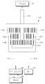
도 1은 본 발명의 일 실시예에 따른 항공기의 하이브리드 구동장치에 대한 구성도이다.
도 2는 도 1에 있어서, 하이브리드 구동장치의 내부를 도시한 사시도이다.
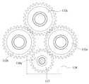
도 3은 도 2에 대한 정면도이다.
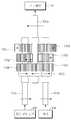
도 4는 도 3에 대한 분해 사시도이다.
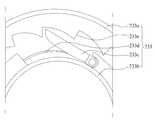
도 5는 도 2에 있어서, 제1 원웨이 클러치의 일 예를 도시한 단면도이다.
도 6은 도 5에 있어서, 제1 원웨이 클러치의 다른 예를 도시한 단면도이다.
도 7 및 도 8은 도 3에 있어서, 단속부의 작용을 설명하기 위한 도면이다.
도 9 내지 도 12는 도 1에 도시된 하이브리드 구동장치의 작용을 설명하기 위한 도면이다.1 is a configuration diagram of a hybrid drive system for an aircraft according to an embodiment of the present invention.
Fig. 2 is a perspective view showing the inside of the hybrid drive system in Fig. 1; Fig.
Figure 3 is a front view of Figure 2;
FIG. 4 is an exploded perspective view of FIG. 3. FIG.
Fig. 5 is a cross-sectional view showing an example of the first one-way clutch in Fig. 2;
Fig. 6 is a cross-sectional view showing another example of the first one-way clutch in Fig. 5;
Fig. 7 and Fig. 8 are views for explaining the action of the intermittent portion in Fig.
9 to 12 are views for explaining the operation of the hybrid driving apparatus shown in FIG.
본 발명에 대해 첨부된 도면을 참조하여 상세히 설명하면 다음과 같다. 여기서, 동일한 구성에 대해서는 동일부호를 사용하며, 반복되는 설명, 본 발명의 요지를 불필요하게 흐릴 수 있는 공지 기능 및 구성에 대한 상세한 설명은 생략한다. 본 발명의 실시형태는 당업계에서 평균적인 지식을 가진 자에게 본 발명을 보다 완전하게 설명하기 위해서 제공되는 것이다. 따라서, 도면에서의 요소들의 형상 및 크기 등은 보다 명확한 설명을 위해 과장될 수 있다.The present invention will now be described in detail with reference to the accompanying drawings. Here, the same reference numerals are used for the same components, and a detailed description of known functions and configurations that may unnecessarily obscure the gist of the present invention will be omitted. Embodiments of the present invention are provided to more fully describe the present invention to those skilled in the art. Accordingly, the shapes and sizes of the elements in the drawings and the like can be exaggerated for clarity.
도 1은 본 발명의 일 실시예에 따른 항공기의 하이브리드 구동장치에 대한 구성도이다. 도 2는 도 1에 있어서, 하이브리드 구동장치의 내부를 도시한 사시도이다. 도 3은 도 2에 대한 정면도이다. 도 4는 도 3에 대한 분해 사시도이다. 도 5는 도 2에 있어서, 제1 원웨이 클러치의 일 예를 도시한 단면도이다.1 is a configuration diagram of a hybrid drive system for an aircraft according to an embodiment of the present invention. Fig. 2 is a perspective view showing the inside of the hybrid drive system in Fig. 1; Fig. Figure 3 is a front view of Figure 2; FIG. 4 is an exploded perspective view of FIG. 3. FIG. Fig. 5 is a cross-sectional view showing an example of the first one-way clutch in Fig. 2;
도 1 내지 도 5를 참조하면, 본 발명의 일 실시예에 따른 항공기의 하이브리드 구동장치(100)는 항공기에 탑재되어 프로펠러(10)를 회전시키는 것으로, 엔진(110)과, 발전 겸용 모터(120), 및 동력전달 유닛(130)을 포함한다.1 to 5, an aircraft hybrid drive system 100 according to an embodiment of the present invention is mounted on an aircraft and rotates a
엔진(110)은 항공유를 연소시켜 동력을 발생시킨다. 엔진(110)은 내연기관으로 이루어질 수 있다. 엔진(110)은 회전 동력을 출력하도록 구성된다. 엔진(110)은 통상적인 구성으로 이루어질 수 있다.The
발전 겸용 모터(120)는 발전 기능과 전동 기능을 구비한다. 발전 겸용 모터(120)는 배터리(140)로부터 전기가 입력되면, 회전 동력을 발생시켜 동력전달 유닛(130)으로 출력한다. 발전 겸용 모터(120)는 동력전달 유닛(130)으로부터 회전력이 입력되면, 전기를 발생시켜 배터리(140)로 출력한다. 발전 겸용 모터(120)는 통상적인 구성으로 이루어질 수 있다.The generator-
동력전달 유닛(130)은 엔진(110)의 구동시 발생된 동력을 프로펠러(10)로 전달함과 동시에 발전 겸용 모터(120)로 전달해서 발전하게 한다. 프로펠러(10)는 동력전달 유닛(130)으로부터 동력을 전달받아 회전함으로써, 항공기를 추진시킨다. 동력전달 유닛(130)은 발전 겸용 모터(120)의 구동시 발생된 동력을 프로펠러(10)로만 전달하며, 엔진(110)으로 전달되지 않게 한다. 또한, 동력전달 유닛(130)은 엔진(110)의 시동시 발전 겸용 모터(120)의 역구동에 의한 동력을 엔진(110)으로 전달한다.The
예컨대, 동력전달 유닛(130)은 제1 샤프트 내지 제3 샤프트(131a, 131b, 131c)와, 제1 기어 내지 제7 기어(132a, 132b, 132c, 132d, 132e, 132f, 132g), 및 단속기(136)를 포함할 수 있다. 제1 내지 제3 샤프트(131a, 131b, 131c)는 프레임(101)에 의해 회전 가능하도록 지지될 수 있다.For example, the power transmitting
제1 샤프트(131a)는 프로펠러(10)에 연결되어 회전한다. 제1 샤프트(131a)는 동력전달 유닛(130)으로부터 회전 동력을 전달받아 회전함에 따라 프로펠러(10)를 회전시킨다. 제2 샤프트(131b)는 엔진(110)에 연결되어 회전한다. 제2 샤프트(131b)는 엔진(110)으로부터 회전 동력을 공급받아 회전한다.The
제3 샤프트(131c)는 발전 겸용 모터(120)에 연결되어 회전한다. 제3 샤프트(131c)는 발전 겸용 모터(120)로부터 회전 동력을 공급받아 회전한다. 제3 샤프트(131c)는 동력전달 유닛(130)으로부터 발전 겸용 모터(120)의 회전 동력 방향과 반대 방향의 회전 동력을 전달받아 회전한다.The
제1 기어(132a)는 제2 샤프트(131b)에 동축으로 삽입된다. 제1 기어(132a)는 제2 샤프트(131b)가 정회전할 때만 제1 원웨이 클러치(133)에 의해 제2 샤프트(131b)의 회전을 전달받는다. 제1 원웨이 클러치(133)는 제2 샤프트(131b)가 정회전할 때만 제2 샤프트(131b)의 회전을 제1 기어(132a)로 전달하며, 제2 샤프트(131b)가 역회전할 때 제2 샤프트(131b)의 회전을 제1 기어(132a)로 전달하지 않는다.The
또한, 제1 원웨이 클러치(133)는 제1 기어(132a)가 제2 샤프트(131b)의 정회전 방향과 반대 방향으로 회전할 때만 제1 기어(132a)의 회전을 제2 샤프트(131b)로 전달하며, 제1 기어(132a)가 제2 샤프트(131b)의 정회전 방향과 동일 방향으로 회전할 때 제1 기어(132a)의 회전을 제2 샤프트(131b)로 전달하지 않는다.The first one-
제1 원웨이 클러치(133)는 제1 기어(132a)와 제2 샤프트(131b) 사이에 장착된다. 제1 원웨이 클러치(133)는 다양하게 구성될 수 있다. 일 예로, 도 5에 도시된 바와 같이, 제1 원웨이 클러치(133)는 외륜(133a)과, 내륜(133b)과, 베어링 볼(133c)들, 및 스프링(133d)들을 포함한다. 외륜(133a)은 제1 기어(132a)의 내주면에 고정될 수 있다. 외륜(133a)의 내주면에는 각각 경사진 형태의 걸림 턱(133e)들이 형성된다. 베어링 볼(133c)들은 걸림 턱(133e)들 사이의 홈들에 각각 삽입되며, 스프링(133d)들에 의해 각각 탄성력으로 지지된다. 내륜(133b)은 외륜(133a) 내에서 동심으로 배치된다. 내륜(133b)은 제2 샤프트(131b)의 외주면에 고정될 수 있다.The first one-
따라서, 도 5를 기준으로, 제2 샤프트(131b)가 반시계 방향으로 회전하면, 베어링 볼(133c)들이 홈들로부터 인출되어 제2 샤프트(131b)를 제1 기어(132a)에 구속함으로써, 제2 샤프트(131b)의 회전이 제1 기어(132a)로 전달되게 한다. 제2 샤프트(131b)가 시계 방향으로 회전하면, 베어링 볼(133c)들이 홈들로부터 인입되어 제2 샤프트(131b)를 제1 기어(132a)로부터 구속 해지함으로써, 제2 샤프트(131b)의 회전이 제1 기어(132a)로 전달되지 않게 한다.5, when the
또한, 제1 기어(132a)가 시계 방향으로 회전하면, 베어링 볼(133c)들이 홈들로부터 인출되어 제1 기어(132a)를 제2 샤프트(131b)에 구속함으로써, 제1 기어(132a)의 회전이 제2 샤프트(131b)로 전달되게 한다. 제1 기어(132a)가 반시계 방향으로 회전하면, 베어링 볼(133c)들이 홈들로부터 인입되어 제1 기어(132a)를 제2 샤프트(131b)로부터 구속 해지함으로써, 제1 기어(132a)의 회전이 제2 샤프트(131b)로 전달되지 않게 한다.When the
다른 예에 따른 제1 원웨이 클러치(233)는 도 6에 도시된 바와 같이 구성될 수 있다. 도 6에 도시된 바에 따르면, 제1 원웨이 클러치(233)는 외륜(233a)의 내주면에 걸림 턱(233e)들이 형성된다. 내륜(233b)의 외주면에 래치(233c)가 피벗 가능하게 설치된다. 래치(233c)는 스프링(233d)에 의해 외륜(233a)의 걸림 턱(233e)들 중 어느 하나에 걸린 상태로 유지한다.The first one-way clutch 233 according to another example may be configured as shown in Fig. 6, the first one-way clutch 233 is formed with
본 예에 따른 제1 원웨이 클러치(233)는 외륜(233a) 또는 내륜(233b)의 회전 방향에 따라 래치(233c)가 걸림 턱(233e)에 걸리거나 해제됨으로써, 전술한 예의 제1 원웨이 클러치(133)와 동일하게 작용할 수 있다. 이 밖에도, 제1 원웨이 클러치(133, 233)는 전술한 기능을 수행하는 범주에서 다양하게 구성될 수 있다.The first one-way clutch 233 according to this example is engaged or released by the
제2 기어(132b)는 제3 샤프트(131c)에 동축으로 삽입된다. 제2 기어(132b)는 제1 기어(132a)의 잇수와 동일한 잇수를 가질 수 있다. 제2 기어(132b)는 제3 샤프트(131c)가 정회전할 때만 제2 원웨이 클러치(134)에 의해 제3 샤프트(131c)의 회전을 전달받는다. 제2 원웨이 클러치(134)는 제2 기어(132b)가 제3 샤프트(131c)의 정회전 방향과 반대 방향으로 회전할 때만 제2 기어(132b)의 회전을 제3 샤프트(131c)로 전달한다. 제2 원웨이 클러치(134)는 제2 기어(132b)와 제3 샤프트(131c) 사이에 장착된다. 제2 원웨이 클러치(134)는 제1 원웨이 클러치(133, 233)와 동일하게 구성될 수 있다.The
제3 기어(132c)는 제1,2 기어(132a, 132b)에 치합된 상태로 제1 샤프트(131a)에 동축으로 고정된다. 제3 기어(132c)는 제1 샤프트(131a)와 함께 회전한다. 제3 기어(132c)는 제1,2 기어(132a, 132b)보다 적은 잇수로 이루어져 제1,2 기어(132a, 132b)보다 빠르게 회전할 수 있다. 제4 기어(132d)는 제1 기어(132a)로부터 이격된 상태로 제2 샤프트(131b)에 동축으로 고정된다. 제4 기어(132d)는 제2 샤프트(131b)와 함께 회전한다.The
제5 기어(132e)는 제4 기어(132d)와 치합된 상태로 제3 샤프트(131c)에 동축으로 삽입된다. 제5 기어(132e)는 제4 기어(132d)의 잇수와 동일한 잇수를 가질 수 있다. 제5 기어(132e)는 제3 샤프트(131c)가 역회전할 때만 제3 원웨이 클러치(135)에 의해 제3 샤프트(131c)의 회전을 전달받는다. 제3 원웨이 클러치(135)는 제5 기어(132e)가 제3 샤프트(131c)의 역회전 방향과 반대 방향으로 회전할 때만 제5 기어(132e)의 회전을 제3 샤프트(131c)로 전달한다. 제3 원웨이 클러치(135)는 제5 기어(132e)와 제3 샤프트(131c) 사이에 장착된다. 제3 원웨이 클러치(135)는 제1 원웨이 클러치(133, 233)와 동일하게 구성될 수 있다.The
제6 기어(132f)는 제1 기어(132a)와 제4 기어(132d) 사이에서 제2 샤프트(131b)에 동축으로 고정된다. 제7 기어(132g)는 제2 기어(132b)와 제5 기어(132e) 사이에서 제3 샤프트(131c)에 동축으로 고정된다. 제7 기어(132g)는 제6 기어(132f)의 잇수와 동일한 잇수를 가질 수 있다.The
단속기(136)는 제6 기어(132f)와 제7 기어(132g) 간에 회전 전달을 단속한다. 예컨대, 단속기(136)는 단속 기어(137)와, 안내 부재(138), 및 탄성 부재(139)를 포함한다. 단속 기어(137)는 제6,7 기어(132f, 132g)에 치합되도록 형성된다. 안내 부재(138)는 단속 기어(137)가 제6 기어(132f)에 치합된 상태에서 제7 기어(132g)와 치합 또는 분리되도록 단속 기어(137)의 이동을 안내한다.The
안내 부재(138)는 일정 간격을 두고 배치된 측벽들을 갖고, 측벽들 사이에 단속 기어(137)를 수용하는 구조로 이루어진다. 안내 부재(138)의 측벽들에는 단속 기어(137)의 양 회전축을 각각 끼우는 안내 홀(138a)이 형성된다. 안내 홀(138a)은 단속 기어(137)가 제6 기어(133f)에 치합된 상태를 유지하면서 제7 기어(132g)와 치합 또는 분리되도록 단속 기어(137)의 이동을 안내하는 궤적을 갖는다.The
탄성 부재(139)는 단속 기어(137)가 제7 기어(132g)로부터 분리되는 방향으로 단속 기어(137)에 탄성력을 가한다. 탄성 부재(139)는 인장 코일스프링으로 이루어질 수 있다. 인장 코일 스프링은 일단이 안내 부재(138)에 고정되고 타단이 단속 기어(137)에 고정될 수 있다.The
예컨대, 제2 샤프트(131b)의 정회전 방향이 시계 방향인 것으로 가정하면, 단속기(137)는 다음과 같이 작용할 수 있다. 단속 기어(137)는 제6 기어(132f)가 엔진(110)의 구동에 의해 시계 방향으로 회전할 때 제7 기어(132g)에 치합되도록 이동한다. 따라서, 제6 기어(132f)의 회전이 제7 기어(132g)로 전달된다. 단속 기어(137)는 제7 기어(132g)가 발전 겸용 모터(120)의 구동에 의해 시계 방향으로 회전할 때 제7 기어(132g)로부터 분리되도록 이동한다. 따라서, 제7 기어(132g)의 회전이 제6 기어(132f)로 전달되지 않는다.For example, if it is assumed that the forward rotation direction of the
전술한 하이브리드 구동장치(100)의 작용을 도 9 내지 도 12를 참조하여 설명하면 다음과 같다. 여기서, 엔진(110)의 구동에 의한 제2 샤프트(131b)의 정회전 방향은 시계 방향이며, 발전 겸용 모터(120)의 구동에 의한 제3 샤프트(131c)의 정회전 방향은 시계 방향인 것으로 가정한다. 이 경우, 제1 원웨이 클러치(133)에 의해, 제2 샤프트(131b)는 시계 방향으로 회전할 때 제1 기어(132a)와 구속되며, 제1 기어(132a)는 반시계 방향으로 회전할 때 제2 샤프트(131b)와 구속된다.The operation of the hybrid drive system 100 will be described with reference to FIGS. 9 to 12. FIG. Here, the forward rotation direction of the
그리고, 제2 원웨이 클러치(134)에 의해, 제3 샤프트(131c)는 시계 방향으로 회전할 때 제2 기어(132b)와 구속되며, 제2 기어(132b)는 반시계 방향으로 회전할 때 제3 샤프트(131c)와 구속된다. 제3 원웨이 클러치(135)에 의해, 제3 샤프트(131c)는 반시계 방향으로 회전할 때 제5 기어(132e)와 구속되며, 제5 기어(132e)는 시계 방향으로 회전할 때 제3 샤프트(131c)와 구속된다.By the second one-
도 9에 도시된 바와 같이, 엔진(110)의 구동에 의해 제2 샤프트(131b)가 시계 방향으로 회전한다. 그러면, 제1 기어(132a)는 제1 원웨이 클러치(133)에 의해 제2 샤프트(131b)에 구속되어 시계 방향으로 회전한다. 그러면, 제3 기어(132c)는 제1 기어(132a)에 의해 반시계 방향으로 회전함에 따라 제1 샤프트(131a)를 함께 회전시키게 된다. 따라서, 제1 샤프트(131a)와 연결된 프로펠러(10)로 엔진(110)의 동력이 전달될 수 있다.As shown in Fig. 9, the
제2 기어(132b)는 제3 기어(132c)에 의해 시계 방향으로 회전하므로, 제2 원웨이 클러치(134)에 의해 제3 샤프트(131c)로부터 구속 해지된다. 따라서, 제2 기어(132b)의 회전은 제3 샤프트(131c)로 전달되지 않는다. 제4 기어(132d)는 제2 샤프트(131b)와 함께 시계 방향으로 회전한다. 그러면, 제5 기어(132e)는 제4 기어(132d)에 의해 반시계 방향으로 회전한다. 제5 기어(132d)는 제3 원웨이 클러치(135)에 의해 제3 샤프트(131c)로부터 구속 해지된다. 따라서, 제5 기어(132e)의 회전은 제3 샤프트(131c)로 전달되지 않는다.The
제6 기어(132f)는 제2 샤프트(131b)와 함께 시계 방향으로 회전한다. 그러면, 단속 기어(137)는 제6 기어(132f)에 치합된 상태를 유지하면서 제7 기어(132g)에 치합되도록 이동한다. 따라서, 제6 기어(132f)의 회전이 제7 기어(132g)로 전달된다. 그러면, 제7 기어(132g)는 시계 방향으로 회전함에 따라 제3 샤프트(131c)를 함께 회전시킨다. 따라서, 제3 샤프트(131c)와 연결된 발전 겸용 모터(120)로 엔진(110)의 동력이 전달되므로, 발전 겸용 모터(120)에서 전기가 발생되어 배터리(140)를 충전시킬 수 있다.And the
이와 같이, 엔진(110)의 구동시 발생된 동력은 프로펠러(10)로 전달되어 추진력을 발생시킴과 동시에, 발전 겸용 모터(120)로 전달되어 배터리(140)를 충전시킬 수 있다.In this way, the power generated when the
도 10에 도시된 바와 같이, 발전 겸용 모터(120)의 구동에 의해 제3 샤프트(131c)가 시계 방향으로 회전한다. 그러면, 제2 기어(132b)는 제2 원웨이 클러치(134)에 의해 제3 샤프트(131c)에 구속되어 시계 방향으로 회전한다. 그러면, 제3 기어(132c)는 제2 기어(132b)에 의해 반시계 방향으로 회전함에 따라 제1 샤프트(131a)를 함께 회전시키게 된다. 따라서, 제1 샤프트(131a)와 연결된 프로펠러(10)로 발전 겸용 모터(120)의 동력이 전달될 수 있다.As shown in Fig. 10, the
제1 기어(132a)는 제3 기어(132c)에 의해 시계 방향으로 회전하므로, 제1 원웨이 클러치(133)에 의해 제2 샤프트(131b)로부터 구속 해지된다. 따라서, 제1 기어(132a)의 회전은 제2 샤프트(131b)로 전달되지 않는다. 제2 샤프트(131b)는 회전하지 않게 되므로, 제4, 6 기어(132d, 132f)는 회전하지 않는다.The
제3 샤프트(131c)가 시계 방향으로 회전하면, 제5 기어(132e)는 제3 원웨이 클러치(135)에 의해 제3 샤프트(131c)로부터 구속 해지된다. 따라서, 제3 샤프트(131c)의 회전은 제5 기어(132e)로 전달되지 않는다. 제7 기어(132g)는 제3 샤프트(131c)에 의해 시계 방향으로 회전한다. 그러면, 단속 기어(137)는 제7 기어(132g)로부터 분리되므로, 제7 기어(132g)의 회전이 제6 기어(132f)로 전달되지 않는다. 이와 같이, 발전 겸용 모터(120)의 구동시 발생된 동력은 프로펠러(10)로만 전달되어 추진력을 발생시킬 수 있다.When the
도 11에 도시된 바와 같이, 엔진(110)의 시동시, 발전 겸용 모터(120)의 역구동에 의해 제3 샤프트(131c)가 반시계 방향으로 회전한다. 그러면, 제2 기어(132b)는 제2 원웨이 클러치(134)에 의해 제3 샤프트(131c)로부터 구속 해지되며, 제5 기어(132e)는 제3 원웨이 클러치(135)에 의해 제3 샤프트(131c)에 구속된다.As shown in Fig. 11, when the
제5 기어(132e)가 반시계 방향으로 회전함에 따라, 제4 기어(132d)가 시계 방향으로 회전하게 된다. 그러면, 제2 샤프트(131b)가 제4 기어(132d)에 의해 시계 방향으로 회전하므로, 제2 샤프트(131b)와 연결된 엔진(110)에 동력을 전달할 수 있다. 따라서, 엔진(110)을 시동시킬 수 있다. 이 과정에서, 제6 기어(132f)는 시계 방향으로 회전하게 되는데, 엔진(110)의 시동이 완료될 때까지 제6 기어(132f)의 회전 속도가 낮으므로, 단속 기어(137)는 제7 기어(132g)로부터 분리된 상태를 유지하게 된다. 따라서, 제7 기어(132g)의 반시계 방향 회전은 제6 기어(132f)로 전달되지 않는다.As the
엔진(110)의 시동이 완료된 후, 발전 겸용 모터(120)의 역구동을 중지시키면, 전술한 바와 같은 엔진(110)의 구동에 의한 작용과 동일하게 작용하게 된다. 한편, 제1 기어(132a)는 제1 원웨이 클러치(133)에 의해 제2 샤프트(131b)에 구속되므로, 시계 방향으로 회전하게 된다. 그러면, 제3 기어(132c)가 반시계 방향으로 회전함에 따라 제1 샤프트(131a)를 통해 프로펠러(10)로 동력을 전달할 수 있다.When the reverse operation of the
도 12에 도시된 바와 같이, 엔진(110)과 발전 겸용 모터(120)를 동시에 구동시키면, 제2, 3 샤프트(131b, 131c)가 시계 방향으로 회전한다. 그러면, 제1 기어(132a)는 제1 원웨이 클러치(133)에 의해 제2 샤프트(131b)에 구속되어 시계 방향으로 회전하며, 제2 기어(132b)는 제2 원웨이 클러치(134)에 의해 제3 샤프트(131c)에 구속되어 시계 방향으로 회전한다. 따라서, 제3 기어(132c)는 제1,2 기어(132a, 132b)에 의해 반시계 방향으로 회전함에 따라 제1 샤프트(131a)를 통해 엔진(110)과 발전 겸용 모터(120)의 동력을 프로펠러(10)로 전달할 수 있게 된다.As shown in FIG. 12, when the
이때, 제3 샤프트(131c)는 시계 방향으로 회전하므로, 제5 기어(132e)는 제3 원웨이 클러치(135)에 의해 제3 샤프트(131c)로부터 구속 해지되므로, 제4 기어(132d)에 의해 반시계 방향으로 회전할 수 있게 된다. 단속 기어(137)는 제7 기어(132g)가 시계 방향으로 회전함에 따라 제7 기어(132g)로부터 분리되어 제6 기어(132f)로 회전을 전달하지 않는다. 이와 같이, 고추력이 필요한 경우, 예컨대 항공기의 수직 이착륙나, 최고속도 비행이 필요한 경우, 엔진(110)과 발전 겸용 모터(120)의 2개 동력을 동시에 사용할 수 있다.At this time, since the
본 발명은 첨부된 도면에 도시된 일 실시예를 참고로 설명되었으나 이는 예시적인 것에 불과하며, 당해 기술분야에서 통상의 지식을 가진 자라면 이로부터 다양한 변형 및 균등한 타 실시예가 가능하다는 점을 이해할 수 있을 것이다. 따라서, 본 발명의 진정한 보호 범위는 첨부된 청구 범위에 의해서만 정해져야 할 것이다.While the present invention has been particularly shown and described with reference to exemplary embodiments thereof, it is clearly understood that the same is by way of illustration and example only and is not to be taken by way of limitation and that those skilled in the art will recognize that various modifications and equivalent arrangements may be made therein. It will be possible. Accordingly, the true scope of protection of the present invention should be determined only by the appended claims.
10..프로펠러110..엔진
120..발전 겸용 모터130..동력전달 유닛
131a..제1 샤프트131b..제2 샤프트
131c..제3 샤프트132a..제1 기어
132b..제2 기어132c..제3 기어
132d..제4 기어132e..제5 기어
132f..제6 기어132g..제7 기어
133..제1 원웨이 클러치134..제2 원웨이 클러치
135..제3 원웨이 클러치137..단속 기어
140..배터리10.
120 .. Motor combined with
131a ..
131c ..
132b ..
132d ..
132f ..
133. First one-
135. Third one way clutch 137 .. Intermittent gear
140 .. Battery
Claims (3)
Translated fromKorean항공유를 연소시켜 동력을 발생시키는 엔진;
발전 기능과 전동 기능을 구비한 발전 겸용 모터; 및
상기 엔진의 구동시 발생된 동력을 상기 프로펠러로 전달함과 동시에 상기 발전 겸용 모터로 전달해서 발전하게 하며, 상기 발전 겸용 모터의 구동시 발생된 동력을 상기 프로펠러로만 전달하며, 상기 엔진의 시동시 상기 발전 겸용 모터의 역구동에 의한 동력을 상기 엔진으로 전달하는 동력전달 유닛;을 포함하며,
상기 동력전달 유닛은,
상기 프로펠러에 연결되어 회전하는 제1 샤프트와,
상기 엔진에 연결되어 회전하는 제2 샤프트와,
상기 발전 겸용 모터에 연결되어 회전하는 제3 샤프트와,
상기 제2 샤프트에 동축으로 삽입되며 상기 제2 샤프트가 정회전할 때만 제1 원웨이 클러치에 의해 상기 제2 샤프트의 회전을 전달받는 제1 기어와,
상기 제3 샤프트에 동축으로 삽입되며 상기 제3 샤프트가 정회전할 때만 제2 원웨이 클러치에 의해 상기 제3 샤프트의 회전을 전달받는 제2 기어와,
상기 제1,2 기어에 치합된 상태로 상기 제1 샤프트에 동축으로 고정된 제3 기어와,
상기 제1 기어로부터 이격된 상태로 상기 제2 샤프트에 동축으로 고정된 제4 기어와,
상기 제4 기어와 치합된 상태로 상기 제3 샤프트에 동축으로 삽입되며 상기 제3 샤프트가 역회전할 때만 제3 원웨이 클러치에 의해 상기 제3 샤프트의 회전을 전달받는 제5 기어와,
상기 제1 기어와 제4 기어 사이에서 상기 제2 샤프트에 동축으로 고정된 제6 기어와,
상기 제2 기어와 제5 기어 사이에서 상기 제3 샤프트에 동축으로 고정된 제7 기어, 및
상기 제6 기어와 제7 기어 간에 회전 전달을 단속하는 단속기를 포함하는 것을 특징으로 하는 항공기의 하이브리드 구동장치.By rotating the propeller mounted on an aircraft,
An engine that burns jet fuel to generate power;
A generator-motor having a generator function and a motor function; And
The power generated when the engine is driven is transmitted to the propeller and is transmitted to the power generation combined motor to generate power, and the power generated when the power generation combined motor is driven is transmitted only to the propeller, And a power transmission unit for transmitting power to the engine by reverse driving of the power generation combined motor,
The power transmitting unit includes:
A first shaft connected to the propeller and rotated,
A second shaft connected to the engine and rotating,
A third shaft connected to the power-generating motor and rotating,
A first gear coaxially inserted into the second shaft and receiving rotation of the second shaft by the first one-way clutch only when the second shaft rotates forward;
A second gear which is coaxially inserted into the third shaft and receives rotation of the third shaft by the second one-way clutch only when the third shaft rotates forward,
A third gear coaxially fixed to the first shaft while being engaged with the first and second gears,
A fourth gear coaxially fixed to the second shaft while being spaced apart from the first gear,
A fifth gear inserted coaxially with the third shaft in a state of meshing with the fourth gear and receiving the rotation of the third shaft by the third one-way clutch only when the third shaft rotates reversely,
A sixth gear coaxially fixed to the second shaft between the first gear and the fourth gear,
A seventh gear coaxially fixed to the third shaft between the second gear and the fifth gear, and
And a stepper for interrupting rotation transmission between the sixth gear and the seventh gear.
상기 단속기는,
상기 제6,7 기어에 치합되도록 형성된 단속 기어와,
상기 단속 기어가 상기 제6 기어에 치합된 상태에서 상기 제7 기어와 치합 또는 분리되도록 상기 단속 기어의 이동을 안내하는 안내 부재, 및
상기 단속 기어가 상기 제7 기어로부터 분리되는 방향으로 상기 단속 기어에 탄성력을 가하는 탄성 부재를 포함하는 것을 특징으로 하는 항공기의 하이브리드 구동장치.3. The method of claim 2,
Wherein,
An intermittent gear formed to mesh with the sixth and seventh gears,
A guide member for guiding the movement of the intermittent gear to engage or disengage with the seventh gear in a state where the intermittent gear is meshed with the sixth gear,
And an elastic member that applies an elastic force to the intermittent gear in a direction in which the intermittent gear is separated from the seventh gear.
Priority Applications (1)
| Application Number | Priority Date | Filing Date | Title |
|---|---|---|---|
| KR1020150083950AKR101713800B1 (en) | 2015-06-15 | 2015-06-15 | Hybrid drive apparatus of aircraft |
Applications Claiming Priority (1)
| Application Number | Priority Date | Filing Date | Title |
|---|---|---|---|
| KR1020150083950AKR101713800B1 (en) | 2015-06-15 | 2015-06-15 | Hybrid drive apparatus of aircraft |
Publications (2)
| Publication Number | Publication Date |
|---|---|
| KR20160147339A KR20160147339A (en) | 2016-12-23 |
| KR101713800B1true KR101713800B1 (en) | 2017-03-08 |
Family
ID=57736009
Family Applications (1)
| Application Number | Title | Priority Date | Filing Date |
|---|---|---|---|
| KR1020150083950AActiveKR101713800B1 (en) | 2015-06-15 | 2015-06-15 | Hybrid drive apparatus of aircraft |
Country Status (1)
| Country | Link |
|---|---|
| KR (1) | KR101713800B1 (en) |
Cited By (6)
| Publication number | Priority date | Publication date | Assignee | Title |
|---|---|---|---|---|
| US11486472B2 (en) | 2020-04-16 | 2022-11-01 | United Technologies Advanced Projects Inc. | Gear sytems with variable speed drive |
| US11535392B2 (en) | 2019-03-18 | 2022-12-27 | Pratt & Whitney Canada Corp. | Architectures for hybrid-electric propulsion |
| US11628942B2 (en) | 2019-03-01 | 2023-04-18 | Pratt & Whitney Canada Corp. | Torque ripple control for an aircraft power train |
| US11697505B2 (en) | 2019-03-01 | 2023-07-11 | Pratt & Whitney Canada Corp. | Distributed propulsion configurations for aircraft having mixed drive systems |
| US11732639B2 (en) | 2019-03-01 | 2023-08-22 | Pratt & Whitney Canada Corp. | Mechanical disconnects for parallel power lanes in hybrid electric propulsion systems |
| US12240619B2 (en) | 2019-03-01 | 2025-03-04 | Pratt & Whitney Canada Corp. | Torque balancing for hybrid electric propulsion systems and aircraft utilizing hybrid electric propulsion systems |
Families Citing this family (6)
| Publication number | Priority date | Publication date | Assignee | Title |
|---|---|---|---|---|
| FR3055883B1 (en)* | 2016-09-09 | 2019-03-29 | Airbus Helicopters | MECHANICAL SYSTEM FOR TRANSMITTING A MOVEMENT AND AIRCRAFT EQUIPPED WITH A CORRESPONDING SYSTEM |
| KR102279741B1 (en)* | 2019-07-12 | 2021-07-20 | (주)창인에이비에이션 | VERTICAL TAKE OFF AND LANDING AIRCRAFT USING HYBRID-ELECTRIC PROPULSION SYSTEM and THE CONTROL METHOD |
| EP3878752B1 (en) | 2018-11-07 | 2024-04-17 | Changinaviation Co., Ltd | Vertical takeoff and landing aircraft using hybrid electric propulsion system and control method therefor |
| EP3931095A4 (en)* | 2019-03-01 | 2022-11-16 | Pratt & Whitney Canada Corp. | AIRCRAFT WITH A HYBRID ELECTRIC PROPULSION SYSTEM WITH IN-WING HOUSED POWER STORAGE |
| EP3931093A4 (en)* | 2019-03-01 | 2022-12-07 | Pratt & Whitney Canada Corp. | AIRPLANE WITH A HYBRID ELECTRIC PROPULSION SYSTEM WITH FUSELAGE-HOUSED POWER STORAGE |
| KR102365065B1 (en)* | 2021-05-06 | 2022-02-23 | 한성산업(주) | Electric fly |
Citations (2)
| Publication number | Priority date | Publication date | Assignee | Title |
|---|---|---|---|---|
| JP2002204504A (en) | 2000-09-14 | 2002-07-19 | Hitachi Ltd | Vehicle power transmission system and vehicle equipped with the same |
| JP2009190458A (en) | 2008-02-12 | 2009-08-27 | Toyota Motor Corp | Power output device and vehicle |
Family Cites Families (2)
| Publication number | Priority date | Publication date | Assignee | Title |
|---|---|---|---|---|
| DE102010021026A1 (en)* | 2010-05-19 | 2011-11-24 | Eads Deutschland Gmbh | Hybrid propulsion and power system for aircraft |
| FR2962404B1 (en)* | 2010-07-08 | 2012-07-20 | Eurocopter France | ELECTRICAL ARCHITECTURE FOR AN AIRCRAFT WITH A HYBRID MOTORIZED TURNING SAIL |
- 2015
- 2015-06-15KRKR1020150083950Apatent/KR101713800B1/enactiveActive
Patent Citations (2)
| Publication number | Priority date | Publication date | Assignee | Title |
|---|---|---|---|---|
| JP2002204504A (en) | 2000-09-14 | 2002-07-19 | Hitachi Ltd | Vehicle power transmission system and vehicle equipped with the same |
| JP2009190458A (en) | 2008-02-12 | 2009-08-27 | Toyota Motor Corp | Power output device and vehicle |
Cited By (8)
| Publication number | Priority date | Publication date | Assignee | Title |
|---|---|---|---|---|
| US11628942B2 (en) | 2019-03-01 | 2023-04-18 | Pratt & Whitney Canada Corp. | Torque ripple control for an aircraft power train |
| US11697505B2 (en) | 2019-03-01 | 2023-07-11 | Pratt & Whitney Canada Corp. | Distributed propulsion configurations for aircraft having mixed drive systems |
| US11732639B2 (en) | 2019-03-01 | 2023-08-22 | Pratt & Whitney Canada Corp. | Mechanical disconnects for parallel power lanes in hybrid electric propulsion systems |
| US12240619B2 (en) | 2019-03-01 | 2025-03-04 | Pratt & Whitney Canada Corp. | Torque balancing for hybrid electric propulsion systems and aircraft utilizing hybrid electric propulsion systems |
| US11535392B2 (en) | 2019-03-18 | 2022-12-27 | Pratt & Whitney Canada Corp. | Architectures for hybrid-electric propulsion |
| US12071256B2 (en) | 2019-03-18 | 2024-08-27 | Pratt & Whitney Canada Corp. | Architectures for hybrid-electric propulsion |
| US11486472B2 (en) | 2020-04-16 | 2022-11-01 | United Technologies Advanced Projects Inc. | Gear sytems with variable speed drive |
| US12066083B2 (en) | 2020-04-16 | 2024-08-20 | Pratt & Whitney Canada Corp. | Gear systems with variable speed drive |
Also Published As
| Publication number | Publication date |
|---|---|
| KR20160147339A (en) | 2016-12-23 |
Similar Documents
| Publication | Publication Date | Title |
|---|---|---|
| KR101713800B1 (en) | Hybrid drive apparatus of aircraft | |
| US8169100B2 (en) | Torque transmission for an aircraft engine | |
| KR101637725B1 (en) | Transmission for hybrid vehicle | |
| EP2664785A2 (en) | Vehicle starter and transmission mechanism for the same | |
| KR101762693B1 (en) | Marine gearbox by using power-split planetary gear-train | |
| KR20160073234A (en) | Hybrid powertrain | |
| JP2017534014A5 (en) | ||
| CN105346712B (en) | Small single-rotor unmanned helicopter transmission system | |
| JP6423201B2 (en) | Driving force transmission device | |
| EP3569507B1 (en) | Aircraft propulsion system | |
| KR101637724B1 (en) | Transmission for hybrid vehicle | |
| CN105332843B (en) | A kind of starter and its starting device and its unidirectional and reducing gear | |
| US10760650B2 (en) | Gear mechanism providing passive ratio switching | |
| US11028778B2 (en) | Engine with start assist | |
| US20120167713A1 (en) | Engine startup device | |
| US10598255B2 (en) | Self-contained reduction gear with two ratios, and system with engine and reversible electrical machine including this reduction gear | |
| CN212951156U (en) | Variable-rotation-speed transmission system and unmanned aerial vehicle | |
| KR102395290B1 (en) | Starter-generator system | |
| RU2556821C2 (en) | Power plant of underwater vehicle | |
| KR101882029B1 (en) | Reverse and Reduction Gear Unit for Marine Propulsion | |
| US8939858B2 (en) | Electrically variable drive unit | |
| EP3715601A1 (en) | Auxiliary power unit with plural spool assembly and starter transmission arrangement | |
| JP2017053454A (en) | Variable Speed Pulley Mechanism | |
| KR101882526B1 (en) | Marine Transmission with Geared PTO Drives | |
| CN204003220U (en) | A kind of starter motor and starting arrangement and its unidirectional and reducing gear |
Legal Events
| Date | Code | Title | Description |
|---|---|---|---|
| A201 | Request for examination | ||
| PA0109 | Patent application | Patent event code:PA01091R01D Comment text:Patent Application Patent event date:20150615 | |
| PA0201 | Request for examination | ||
| E902 | Notification of reason for refusal | ||
| PE0902 | Notice of grounds for rejection | Comment text:Notification of reason for refusal Patent event date:20160714 Patent event code:PE09021S01D | |
| E701 | Decision to grant or registration of patent right | ||
| PE0701 | Decision of registration | Patent event code:PE07011S01D Comment text:Decision to Grant Registration Patent event date:20161201 | |
| PG1501 | Laying open of application | ||
| GRNT | Written decision to grant | ||
| PR0701 | Registration of establishment | Comment text:Registration of Establishment Patent event date:20170302 Patent event code:PR07011E01D | |
| PR1002 | Payment of registration fee | Payment date:20170303 End annual number:3 Start annual number:1 | |
| PG1601 | Publication of registration | ||
| PR1001 | Payment of annual fee | Payment date:20200902 Start annual number:4 End annual number:4 | |
| PR1001 | Payment of annual fee | Payment date:20220303 Start annual number:6 End annual number:6 | |
| PR1001 | Payment of annual fee | Payment date:20230303 Start annual number:7 End annual number:7 | |
| PR1001 | Payment of annual fee | Payment date:20240304 Start annual number:8 End annual number:8 | |
| PR1001 | Payment of annual fee | Payment date:20250304 Start annual number:9 End annual number:9 |