KR101713238B1 - Tire monitoring device and vehicle comprising the same - Google Patents
Tire monitoring device and vehicle comprising the sameDownload PDFInfo
- Publication number
- KR101713238B1 KR101713238B1KR1020160059777AKR20160059777AKR101713238B1KR 101713238 B1KR101713238 B1KR 101713238B1KR 1020160059777 AKR1020160059777 AKR 1020160059777AKR 20160059777 AKR20160059777 AKR 20160059777AKR 101713238 B1KR101713238 B1KR 101713238B1
- Authority
- KR
- South Korea
- Prior art keywords
- wireless power
- sensor
- pneumatic tires
- unit
- information
- Prior art date
- Legal status (The legal status is an assumption and is not a legal conclusion. Google has not performed a legal analysis and makes no representation as to the accuracy of the status listed.)
- Active
Links
- 238000012806monitoring deviceMethods0.000titleclaimsdescription4
- 230000005540biological transmissionEffects0.000claimsdescription35
- 230000010365information processingEffects0.000claimsdescription18
- 238000000034methodMethods0.000claimsdescription18
- 238000012544monitoring processMethods0.000claimsdescription12
- 238000010168coupling processMethods0.000claimsdescription7
- 238000007599dischargingMethods0.000claimsdescription6
- 230000008569processEffects0.000claimsdescription6
- 239000010410layerSubstances0.000description26
- 238000006243chemical reactionMethods0.000description12
- 239000011324beadSubstances0.000description11
- 238000010586diagramMethods0.000description7
- 229920001971elastomerPolymers0.000description6
- 229910000831SteelInorganic materials0.000description5
- 230000008859changeEffects0.000description5
- 230000008878couplingEffects0.000description5
- 238000005859coupling reactionMethods0.000description5
- 239000010959steelSubstances0.000description5
- XLYOFNOQVPJJNP-UHFFFAOYSA-NwaterSubstancesOXLYOFNOQVPJJNP-UHFFFAOYSA-N0.000description3
- 230000001133accelerationEffects0.000description2
- 239000011248coating agentSubstances0.000description2
- 238000000576coating methodMethods0.000description2
- 230000000694effectsEffects0.000description2
- 230000005672electromagnetic fieldEffects0.000description2
- 239000000945fillerSubstances0.000description2
- 230000001939inductive effectEffects0.000description2
- 229920000728polyesterPolymers0.000description2
- 238000005096rolling processMethods0.000description2
- 229920000297RayonPolymers0.000description1
- XUIMIQQOPSSXEZ-UHFFFAOYSA-NSiliconChemical compound[Si]XUIMIQQOPSSXEZ-UHFFFAOYSA-N0.000description1
- 230000032683agingEffects0.000description1
- 238000005452bendingMethods0.000description1
- 229920005549butyl rubberPolymers0.000description1
- 230000007547defectEffects0.000description1
- 239000004744fabricSubstances0.000description1
- 239000000835fiberSubstances0.000description1
- 230000005484gravityEffects0.000description1
- 238000010030laminatingMethods0.000description1
- 239000007788liquidSubstances0.000description1
- 238000012986modificationMethods0.000description1
- 230000004048modificationEffects0.000description1
- 239000011368organic materialSubstances0.000description1
- 239000002964rayonSubstances0.000description1
- 230000004044responseEffects0.000description1
- 238000000926separation methodMethods0.000description1
- 229910052710siliconInorganic materials0.000description1
- 239000010703siliconSubstances0.000description1
- 239000002356single layerSubstances0.000description1
- 229920002994synthetic fiberPolymers0.000description1
- 239000012209synthetic fiberSubstances0.000description1
Images


Classifications
- B—PERFORMING OPERATIONS; TRANSPORTING
- B60—VEHICLES IN GENERAL
- B60C—VEHICLE TYRES; TYRE INFLATION; TYRE CHANGING; CONNECTING VALVES TO INFLATABLE ELASTIC BODIES IN GENERAL; DEVICES OR ARRANGEMENTS RELATED TO TYRES
- B60C23/00—Devices for measuring, signalling, controlling, or distributing tyre pressure or temperature, specially adapted for mounting on vehicles; Arrangement of tyre inflating devices on vehicles, e.g. of pumps or of tanks; Tyre cooling arrangements
- B60C23/001—Devices for manually or automatically controlling or distributing tyre pressure whilst the vehicle is moving
- B60C23/002—Devices for manually or automatically controlling or distributing tyre pressure whilst the vehicle is moving by monitoring conditions other than tyre pressure or deformation
- B—PERFORMING OPERATIONS; TRANSPORTING
- B60—VEHICLES IN GENERAL
- B60C—VEHICLE TYRES; TYRE INFLATION; TYRE CHANGING; CONNECTING VALVES TO INFLATABLE ELASTIC BODIES IN GENERAL; DEVICES OR ARRANGEMENTS RELATED TO TYRES
- B60C23/00—Devices for measuring, signalling, controlling, or distributing tyre pressure or temperature, specially adapted for mounting on vehicles; Arrangement of tyre inflating devices on vehicles, e.g. of pumps or of tanks; Tyre cooling arrangements
- B60C23/02—Signalling devices actuated by tyre pressure
- B60C23/04—Signalling devices actuated by tyre pressure mounted on the wheel or tyre
- B60C23/0408—Signalling devices actuated by tyre pressure mounted on the wheel or tyre transmitting the signals by non-mechanical means from the wheel or tyre to a vehicle body mounted receiver
- B60C23/041—Means for supplying power to the signal- transmitting means on the wheel
- B60C23/0413—Wireless charging of active radio frequency circuits
Landscapes
- Engineering & Computer Science (AREA)
- Mechanical Engineering (AREA)
- Computer Networks & Wireless Communication (AREA)
- Tires In General (AREA)
Abstract
Translated fromKoreanDescription
Translated fromKorean본 발명의 실시예들은, 타이어 모니터링 장치 및 이를 구비한 차량에 관한 것이다.Embodiments of the present invention relate to a tire monitoring apparatus and a vehicle having the same.
차량 운전자의 안전을 보장하고 운전의 편의를 돕기 위한 기술로는 차량용 레이더, 타이어 공기압 감지 장치, 원격시동 장치, 지리정보시스템 등이 있다. 한편 타이어는 차량의 수많은 부품들 중 도로와 직접 접촉하는 부품으로써, 차량의 하중을 지탱하고, 차량의 구동력 및 제동력을 지면으로 전달하며, 노면에서의 충격을 완화하는 등의 기능을 수행하는바, 타이어의 상태는 운전자의 안전에 직접적인 관련이 있다. 이를 위해 주행 중의 타이어의 상태를 지속적으로 모니터링 할 필요가 있다. 예를 들어, 타이어 공기압 감지 장치는 휠에 장착된 센서에서 타이어의 압력 및 온도를 측정하고, 이를 사용자에게 알려줌으로써, 타이어의 결함 발생을 미연에 방지하도록 할 수 있다. 한편, 종래에는 센서에 전선이 연결되거나, 센서가 건전지 등을 구비함으로써, 센서의 구동에 필요한 전력을 공급하였다.Techniques for ensuring the safety of the driver and facilitating driving include vehicle radar, tire pressure sensor, remote starting device, and geographic information system. On the other hand, a tire is a part that directly contacts with the road among a large number of parts of the vehicle, carries the load of the vehicle, transmits the driving force and the braking force of the vehicle to the ground, and mitigates the impact on the road surface. The condition of the tire is directly related to the safety of the driver. For this purpose, it is necessary to continuously monitor the condition of the tires while driving. For example, a tire air pressure sensor measures the pressure and temperature of a tire in a sensor mounted on a wheel, and informs the user of the pressure and temperature of the tire, thereby preventing a defect in the tire from occurring. On the other hand, conventionally, a wire is connected to a sensor, or a sensor is provided with a battery or the like, thereby supplying power necessary for driving the sensor.
그러나, 전선을 연결하여 전력을 센서로 공급하는 경우, 타이어 장탈착 작업이 까다로워지고, 주행 중 전선의 노화 또는 피로 파괴 현상으로 인해 단선이 발생할 수도 있다. 또한, 건전지를 삽입할 경우, 건전지가 완전히 방전되면 센서로부터 데이터를 받지 못하게 되고, 건전지를 교체할 때마다 타이어를 장탈착해야 하는 번거로움이 있으며, 건전지의 수명을 늘리기 위해 복수 개의 건전지를 사용하면, 센서의 토탈 중량이 증가해서 차량 주행 시 발생되는 관성과 진동으로 인해 센서가 이탈될 가능성이 높아진다.However, when electric power is supplied to the sensor by connecting the electric wires, it is difficult to remove the tire from the tire, and the wire may be damaged due to aging or fatigue breakage during running. In addition, when the battery is inserted, when the battery is completely discharged, the data is not received from the sensor, and it is troublesome to remove and remove the tire every time the battery is replaced. In order to increase the life of the battery, , The total weight of the sensor is increased, and the possibility that the sensor is detached due to inertia and vibration generated when the vehicle travels is increased.
본 발명의 실시예들은, 타이어 내부에 위치한 센서부로 무선전력을 효율적으로 공급할 수 있는 타이어 모니터링 장치 및 이를 구비한 차량을 제공한다.Embodiments of the present invention provide a tire monitoring apparatus capable of efficiently supplying wireless power to a sensor unit located inside a tire and a vehicle having the same.
본 발명의 일 실시예는, 차량 본체에 장착된 복수의 공기입 타이어들 내부에 각각 위치하는 복수의 센서부들, 상기 복수의 공기입 타이어들 내부에 각각 위치하고, 상기 복수의 센서부들로 전력을 공급하는 복수의 무선 전력 수신부들, 및 상기 복수의 무선 전력 수신부들과 대응하여 상기 복수의 무선 전력 수신부들로 무선 전력을 각각 송신하는 복수의 무선 전력 송신부들을 포함하고, 상기 복수의 공기입 타이어들 각각은, 트레드, 상기 트레드의 양측 단부에 각각 배치된 한 쌍의 사이드 월들, 및 상기 트레드와 상기 한 쌍의 사이드 월들 내측에 위치하여 상기 공기입 타이어의 내부 공기압을 유지시키는 이너라이너를 포함하고, 상기 복수의 센서부들은, 상기 복수의 공기입 타이어들의 상기 이너라이너 상에 배치된 타이어 모니터링 장치를 개시한다.According to an embodiment of the present invention, there is provided an airbag device comprising: a plurality of sensor units respectively disposed in a plurality of pneumatic tires mounted on a vehicle body; a plurality of sensor units positioned respectively in the plurality of pneumatic tires, And a plurality of radio power transmitters for respectively transmitting radio power to the plurality of radio power receivers in correspondence with the plurality of radio power receivers, A pair of sidewalls disposed at both side ends of the tread and an inner liner positioned inside the tread and the pair of sidewalls to maintain the internal air pressure of the pneumatic tire, The plurality of sensor units may include a plurality of pneumatic tires, .
본 실시예에 있어서, 상기 복수의 센서부들은, 상기 트레드와 중첩한 위치에서 상기 이너라이너 상에 배치될 수 있다.In the present embodiment, the plurality of sensor portions may be disposed on the inner liner in a position overlapping the tread.
본 실시예에 있어서, 상기 복수의 센서부들에 의해 감지된 정보를 수신하여 처리하는 정보처리부와, 상기 정보처리부에 의해 처리된 정보를 표시하는 표시부를 포함할 수 있다.In this embodiment, the information processing unit may include an information processing unit for receiving and processing information sensed by the plurality of sensor units, and a display unit for displaying information processed by the information processing unit.
본 실시예에 있어서, 상기 복수의 센서부들에 의해 감지된 상기 정보는, 상기 차량의 주행 중의 상기 복수의 공기입 타이어들의 상태 및 노면 상태 중 적어도 어느 하나일 수 있다.In the present embodiment, the information sensed by the plurality of sensor units may be at least one of a state of the plurality of pneumatic tires while the vehicle is running, and a road surface state.
본 실시예에 있어서, 상기 복수의 센서부들 각각은, 상기 정보를 감지하는 적어도 하나의 센서, 상기 적어도 하나의 센서에서 감지한 상기 정보를 상기 정보처리부로 전송하는 정보 송신부, 및 상기 복수의 무선 전력 수신부에서 공급하는 상기 전력을 충전 및 방전하는 충전부를 포함할 수 있다.Each of the plurality of sensor units may include at least one sensor for sensing the information, an information transmission unit for transmitting the information sensed by the at least one sensor to the information processing unit, And a charging unit charging and discharging the power supplied from the receiving unit.
본 실시예에 있어서, 상기 복수의 공기입 타이어들 각각은 휠을 포함하고, 상기 복수의 공기입 타이어들의 상기 무선 전력 수신부는 상기 트레드와 중첩하여 배치되며, 상기 복수의 공기입 타이어들의 상기 무선 전력 송신부는 상기 휠의 드롭 센터 상에 배치될 수 있다.In this embodiment, each of the plurality of pneumatic tires includes a wheel, and the wireless power receiver of the plurality of pneumatic tires is disposed over the tread, and the wireless power of the plurality of pneumatic tires The transmitter may be disposed on the drop center of the wheel.
본 실시예에 있어서, 상기 무선 전력 수신부와 상기 무선 전력 송신부는 서로 마주 보게 배치될 수 있다.In the present embodiment, the wireless power receiving unit and the wireless power transmitting unit may be arranged to face each other.
본 실시예에 있어서, 상기 복수의 공기입 타이어들의 상기 무선 전력 수신부는 상기 한 쌍의 사이드월들 중 어느 하나의 사이드월과 중첩하여 배치될 수 있다.In this embodiment, the wireless power receiving portion of the plurality of pneumatic tires may be arranged to overlap with a sidewall of any one of the pair of sidewalls.
본 실시예에 있어서, 상기 어느 하나의 사이드월은 상기 차량 본체에 인접한 측이며, 상기 무선 전력 송신부들은 상기 차량 본체에 위치할 수 있다.In this embodiment, the one sidewall is a side adjacent to the vehicle body, and the wireless power transmission units may be located in the vehicle body.
본 발명의 다른 실시예는, 차량 본체, 상기 차량 본체에 장착된 복수의 공기입 타이어들 및 주행중의 상기 복수의 공기입 타이어들의 상태 및 노면 상태 중 적어도 어느 하나를 감지하고 이를 표시하는 타이어 모니터링 장치를 포함하고, 상기 복수의 공기입 타이어들 각각은, 트레드, 상기 트레드의 양측 단부에 각각 배치된 한 쌍의 사이드 월들, 및 상기 트레드와 상기 한 쌍의 사이드 월들 내측에 위치하여 상기 공기입 타이어의 내부 공기압을 유지시키는 이너라이너를 포함하며, 상기 타이어 모니터링 장치는, 상기 공기입 타이어들 내부에 각각 위치하는 복수의 센서부들을 포함하고, 상기 복수의 센서부들은 상기 공기입 타이어들의 상기 트레드와 중첩한 위치에서 상기 이너라이너 상에 배치된 차량을 개시한다.Another embodiment of the present invention is a tire monitoring apparatus for detecting and indicating at least any one of a state of a vehicle body, a plurality of pneumatic tires mounted on the vehicle body, and a state and a road surface state of the plurality of pneumatic tires in- Each of the plurality of pneumatic tires comprising: a tread, a pair of sidewalls disposed at opposite ends of the tread, and a sidewall disposed within the tread and the pair of sidewalls, Wherein the tire monitoring device includes a plurality of sensor portions each located within the pneumatic tires, the plurality of sensor portions overlapping the tread of the pneumatic tires Discloses a vehicle disposed on the inner liner in one position.
본 실시예에 있어서, 상기 타이어 모니터링 장치는, 상기 공기입 타이어들 내부에 각각 위치하고, 상기 복수의 센서부들로 전력을 공급하는 복수의 무선 전력 수신부들과, 상기 복수의 무선 전력 수신부들과 대응하여 상기 복수의 무선 전력 수신부들로 무선 전력을 각각 송신하는 복수의 무선 전력 송신부들을 포함하고, 상기 복수의 무선 전력 송신부들은 상기 차량 본체의 배터리로부터 전력을 공급받을 수 있다.In the present embodiment, the tire monitoring apparatus includes a plurality of wireless power receivers, each of which is located inside the pneumatic tires and supplies power to the plurality of sensor units, and a plurality of wireless power receivers corresponding to the plurality of wireless power receivers And a plurality of wireless power transmitters for transmitting wireless power to the plurality of wireless power receivers, respectively, and the plurality of wireless power transmitters can receive power from the battery of the vehicle body.
본 실시예에 있어서, 상기 복수의 공기입 타이어들 각각은 휠을 포함하고, 상기 복수의 공기입 타이어들의 상기 무선 전력 수신부는 상기 트레드와 중첩하여 배치되며, 상기 복수의 공기입 타이어들의 상기 무선 전력 송신부는 상기 휠의 드롭 센터 상에 배치될 수 있다.In this embodiment, each of the plurality of pneumatic tires includes a wheel, and the wireless power receiver of the plurality of pneumatic tires is disposed over the tread, and the wireless power of the plurality of pneumatic tires The transmitter may be disposed on the drop center of the wheel.
본 실시예에 있어서, 상기 무선 전력 수신부와 상기 무선 전력 송신부는 서로 대향하여 배치될 수 있다.In the present embodiment, the wireless power receiving unit and the wireless power transmitting unit may be disposed opposite to each other.
본 실시예에 있어서, 상기 복수의 공기입 타이어들의 상기 무선 전력 수신부는 상기 한 쌍의 사이드월들 중 어느 하나의 사이드월과 중첩하여 배치될 수 있다.In this embodiment, the wireless power receiving portion of the plurality of pneumatic tires may be arranged to overlap with a sidewall of any one of the pair of sidewalls.
본 실시예에 있어서, 상기 어느 하나의 사이드월은 상기 차량 본체에 인접한 측이며, 상기 무선 전력 송신부들은 상기 차량 본체에 위치할 수 있다.In this embodiment, the one sidewall is a side adjacent to the vehicle body, and the wireless power transmission units may be located in the vehicle body.
본 실시예에 있어서, 상기 타이어 모니터링 장치는, 상기 복수의 센서부들에 의해 감지된 상기 복수의 공기입 타이어들의 상태 및 상기 노면 상태 중 적어도 어느 하나에 대한 정보를 수신하여 처리하는 정보처리부와, 상기 정보처리부에 의해 처리된 정보를 표시하는 표시부를 포함할 수 있다.In the present embodiment, the tire monitoring apparatus includes an information processing unit for receiving and processing information on at least one of the state of the plurality of pneumatic tires sensed by the plurality of sensor units and the road surface state, And a display unit for displaying information processed by the information processing unit.
본 실시예에 있어서, 상기 복수의 센서부들 각각은, 적어도 하나의 센서, 상기 적어도 하나의 센서에서 감지한 상기 정보를 상기 정보처리부로 전송하는 정보 송신부, 및 상기 복수의 무선 전력 수신부에서 공급하는 상기 전력을 충전 및 방전하는 충전부를 포함할 수 있다.Each of the plurality of sensor units may include at least one sensor, an information transmission unit that transmits the information sensed by the at least one sensor to the information processing unit, And a charging unit for charging and discharging electric power.
전술한 것 외의 다른 측면, 특징, 이점이 이하의 도면, 특허청구범위 및 발명의 상세한 설명으로부터 명확해질 것이다.Other aspects, features, and advantages will become apparent from the following drawings, claims, and detailed description of the invention.
본 발명의 실시예들에 의하면, 타이어 내부에 위치한 센서부로 무선 전력을 효율적으로 공급할 수 있다. 물론 이러한 효과에 의해 본 발명의 범위가 한정되는 것은 아니다.According to embodiments of the present invention, wireless power can be efficiently supplied to a sensor unit located in a tire. Of course, the scope of the present invention is not limited by these effects.
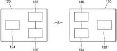
도 1은 본 발명의 일 실시예에 따른 차량을 개략적으로 도시한 평면도이다.
도 2는 본 발명의 일 실시예에 따른 타이어 모니터링 장치의 구성의 일 예를 개략적으로 도시한 블록도이다.
도 3은 도 2의 센서부와 정보처리부의 구성의 일 예를 개략적으로 도시한 블록도이다.
도 4는 도 2의 무선전력 수신부와 무선전력 송신부의 구성의 일 예를 개략적으로 도시한 블록도이다.
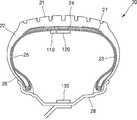
도 5는 도 1의 타이어의 단면을 개략적으로 도시한 단면도이다.
도 6은 도 1의 A 부분을 개략적으로 도시한 평면도이다.1 is a plan view schematically showing a vehicle according to an embodiment of the present invention.
2 is a block diagram schematically illustrating an example of the configuration of a tire monitoring apparatus according to an embodiment of the present invention.
3 is a block diagram schematically showing an example of the configuration of the sensor unit and the information processing unit of FIG.
4 is a block diagram schematically showing an example of the configuration of the wireless power receiver and the wireless power transmitter of FIG.
Fig. 5 is a cross-sectional view schematically showing a cross section of the tire of Fig. 1;
6 is a plan view schematically showing a portion A in Fig.
본 발명은 다양한 변환을 가할 수 있고 여러 가지 실시예를 가질 수 있는 바, 특정 실시예들을 도면에 예시하고 상세한 설명에 상세하게 설명하고자 한다. 본 발명의 효과 및 특징, 그리고 그것들을 달성하는 방법은 도면과 함께 상세하게 후술되어 있는 실시예들을 참조하면 명확해질 것이다. 그러나 본 발명은 이하에서 개시되는 실시예들에 한정되는 것이 아니라 다양한 형태로 구현될 수 있다.BRIEF DESCRIPTION OF THE DRAWINGS The present invention is capable of various modifications and various embodiments, and specific embodiments are illustrated in the drawings and described in detail in the detailed description. The effects and features of the present invention and methods of achieving them will be apparent with reference to the embodiments described in detail below with reference to the drawings. However, the present invention is not limited to the embodiments described below, but may be implemented in various forms.
이하, 첨부된 도면을 참조하여 본 발명의 실시예들을 상세히 설명하기로 하며, 도면을 참조하여 설명할 때 동일하거나 대응하는 구성 요소는 동일한 도면부호를 부여하고 이에 대한 중복되는 설명은 생략하기로 한다.Hereinafter, exemplary embodiments of the present invention will be described in detail with reference to the accompanying drawings, wherein like reference numerals refer to like or corresponding components throughout the drawings, and a duplicate description thereof will be omitted .
이하의 실시예에서, 제1, 제2 등의 용어는 한정적인 의미가 아니라 하나의 구성 요소를 다른 구성 요소와 구별하는 목적으로 사용되었다.In the following embodiments, the terms first, second, and the like are used for the purpose of distinguishing one element from another element, not the limitative meaning.
이하의 실시예에서, 단수의 표현은 문맥상 명백하게 다르게 뜻하지 않는 한, 복수의 표현을 포함한다.In the following examples, the singular forms "a", "an" and "the" include plural referents unless the context clearly dictates otherwise.
이하의 실시예에서, 포함하다 또는 가지다 등의 용어는 명세서상에 기재된 특징, 또는 구성요소가 존재함을 의미하는 것이고, 하나 이상의 다른 특징들 또는 구성요소가 부가될 가능성을 미리 배제하는 것은 아니다.In the following embodiments, terms such as inclusive or possessive are intended to mean that a feature, or element, described in the specification is present, and does not preclude the possibility that one or more other features or elements may be added.
이하의 실시예에서, 구성 요소 등의 부분이 다른 부분 위에 또는 상에 있다고 할 때, 다른 부분의 바로 위에 있는 경우뿐만 아니라, 그 중간에 구성 요소 등이 개재되어 있는 경우도 포함한다.In the following embodiments, when a portion of an element or the like is on or on another portion, the present invention includes not only a case where the portion is directly on another portion, but also a case where an element or the like is interposed in between.
도면에서는 설명의 편의를 위하여 구성 요소들이 그 크기가 과장 또는 축소될 수 있다. 예컨대, 도면에서 나타난 각 구성의 크기 및 두께는 설명의 편의를 위해 임의로 나타내었으므로, 본 발명이 반드시 도시된 바에 한정되지 않는다.In the drawings, components may be exaggerated or reduced in size for convenience of explanation. For example, the size and thickness of each component shown in the drawings are arbitrarily shown for convenience of explanation, and thus the present invention is not necessarily limited to those shown in the drawings.
도 1은 본 발명의 일 실시예에 따른 차량을 개략적으로 도시한 평면도, 도 2는 본 발명의 일 실시예에 따른 타이어 모니터링 장치의 구성의 일 예를 개략적으로 도시한 블록도, 도 3은 도 2의 센서부와 정보처리부의 구성의 일 예를 개략적으로 도시한 블록도, 도 4는 도 2의 무선전력 수신부와 무선전력 송신부의 구성의 일 예를 개략적으로 도시한 블록도, 도 5는 도 1의 타이어의 단면을 개략적으로 도시한 단면도, 그리고 도 6은 도 1의 A 부분을 개략적으로 도시한 평면도이다.2 is a block diagram schematically illustrating an example of the configuration of a tire monitoring apparatus according to an embodiment of the present invention. FIG. 3 is a block diagram FIG. 4 is a block diagram schematically showing an example of the configuration of the wireless power receiving unit and the wireless power transmitting unit of FIG. 2, and FIG. 5 is a block diagram 1 is a cross-sectional view schematically showing a cross-section of a tire of Fig. 1, and Fig. 6 is a plan view schematically showing a portion A of Fig.
먼저, 도 1 내지 도 5를 참조하면, 본 발명의 일 실시예에 따른 차량(1)은 차량 본체(10), 차량 본체(10)에 장착된 복수의 공기입 타이어(20)들, 및 차량(1)의 주행중의 복수의 공기입 타이어(20)들의 상태 및 노면 상태 중 적어도 어느 하나를 감지하고 이를 표시하는 타이어 모니터링 장치(100)를 포함할 수 있다.1 to 5, a
차량 본체(10)는 차량(1)의 외관을 형성하며, 운전자 등이 탑승할 수 있고, 주행을 위한 엔진, 배터리 등이 탑재된다.The
복수의 공기입 타이어(20)들은 휠과 결합하여 차량 본체(10)에 장착될 수 있다. 복수의 공기입 타이어(20)들 각각은, 트레드(21), 트레드(21)의 양측 단부에 각각 배치된 한 쌍의 사이드 월(22)들, 트레드(21)와 한 쌍의 사이드 월(22)들 내측에 위치하여 공기입 타이어(20)의 내부 공기압을 유지시키는 이너라이너(23)를 포함할 수 있다. 또한, 공기입 타이어(20)는 사이드 월(22)들 각각의 하부에 위치한 비드부(26), 트레드(21)의 아래에 위치하는 벨트층(24)과 카카스층(25)을 포함할 수 있으며, 트레드(21)와 벨트층(24) 사이에는 캡 플라이(27)가 더 포함될 수 있다.A plurality of pneumatic tires (20) can be mounted on the vehicle body (10) in combination with the wheel. Each of the plurality of
트레드(21)는, 두꺼운 고무층으로 이루져 차량(1)의 구동력 및 제동력을 지면에 전달한다. 트레드(21)의 표면에는 조종 안정성, 견인력, 제동성을 위한 트레드 패턴들과 트레드 패턴들에 의해 구획된 블록들이 위치할 수 있다. 트레드 패턴들은 젖은 노면에서의 주행 시 배수를 위한 그루브와 견인력 및 제동력을 향상시키기 위한 사이프를 포함할 수 있다. 그루브는 차량의 주행방향과 일치하는 원주방향 그루브와 원주방향 그루브 사이의 횡방향 그루브를 포함할 수 있다. 사이프는 블록에 형성되며, 그루브보다 작은 크기를 가진 홈일 수 있다. 사이프는 젖은 노면에서의 주행시 수분을 흡수하여 수막을 끊는 역할을 함으로써, 공기입 타이어(20)의 구동력과 제동력을 증가시킬 수 있다. 블록은 트레드(21)의 대부분을 차지하는 영역으로, 지면과 직접 접하여 차량의 구동력 및 제동력을 지면에 전달한다.The
사이드 월(22)은 트레드(21)의 단부로부터 하방으로 연장되어 배치된다. 사이드 월(22)은 공기입 타이어(20)의 옆부분으로, 카카스층(25)을 보호하고, 공기입 타이어(20)의 측면 안정성을 제공하며, 굴신운동을 함으로써 승차감을 높일 수 있다. 또한, 사이드 월(22)은 드라이브 샤프트를 통해 받은 엔진의 토크를 트레드(21)에 전달하는 역할을 한다.The
비드부(26)는 사이드 월(22)의 단부에 구비되며, 공기입 타이어(20)를 림(28)에 장착시키는 역할을 한다. 비드부(26)는 비드 코어와 비드 충전재를 포함할 수 있다. 비드 코어는 고무가 코팅된 강철 와이어를 복수 개 꼬아 형성될 수 있으며, 비드 충전재는 비드 코어에 부착된 고무일 수 있다.The
카카스층(25)은 공기입 타이어(20)의 골격을 형성하며, 공기입 타이어(20)가 받는 하중, 충격 등을 견디고 공기입 타이어(20)의 공기압을 유지시킨다. 카카스층(25)은 스틸 또는 폴리에스터, 레이온 등과 같은 고강도 섬유 유기재로 이루어지는 복수의 코드지를 겹친 후, 고무로 피복하여 압연 가공하여 형성될 수 있다 일 실시예로, 카카스층(25)은 서로 중첩된 제1 카카스층과 제2 카카스층을 포함할 수 있다. 제1 카카스층은 비드부(26)에서 턴업되어 트레드(21)를 향해 연장된다. 턴업된 제1 카카스층의 일 단부는 사이드 월(22)의 내측을 커버하도록 연장되어 사이드 월(22)의 강성을 향상시킬 수 있다. 제2 카카스층은 제1 카카스층의 외측에 위치하며, 비드부(26)에서 턴업되어 트레드(21)를 향해 연장되되, 턴업된 제2 카카스층의 일 단부는 제1 카카스층의 일 단부보다 짧게 형성되어 비드부(26)의 내측을 커버할 수 있다. 본 실시예에서는, 카카스층(25)이 2개의 카카스층으로 형성된 구조를 설명하였으나, 본 발명은 이에 한정되지 않는다. 또 다른 실시예로서, 카카스층(25)은 단일 층으로 형성될 수 있다.The
트레드(21)와 카카스층(25) 사이의 벨트층(24)은 차량의 주행(1)시 노면 충격을 감소시키고, 노면에 닿은 트레드(21) 부위를 넓게 하여 주행 안정성을 향상시킬 수 있으며, 트레드(21)와 카카스층(25)의 분리를 방지할 수 있다. 벨트층(24)은 스틸로 이루어지는 복수의 벨트 코드를 고무로 피복하여 압연 가공으로 형성될 수 있다.The
트레드(21)와 벨트층(24) 사이에는 캡 플라이(27)가 더 포함될 수 있다. 캡 플라이(27)는 벨트층(24) 위에 부착되는 특수코드지로 주행시 성능을 향상시킬 수 있다. 캡 플라이(27)는 일 예로 폴리에스테르 합성섬유를 포함하여 이루어질 수 있다.A cap ply 27 may further be included between the
이너라이너(23)는 튜브대신 공기입 타이어(20)의 공기 누출을 방지하는 층으로, 밀폐성이 우수한 고무층으로 이루어질 수 있다. 일 예로, 이너라이너(23)는 밀도가 높은 부틸고무 등으로 이루어질 수 있으며, 공기입 타이어(20) 내의 공기압을 유지시킬 수 있다.The
타이어 모니터링 장치(100)는 복수의 센서부(110)들, 복수의 센서부(110)들로 전력을 공급하는 복수의 무선 전력 수신부(120)들, 복수의 무선 전력 수신부(120)들과 대응하여 복수의 무선 전력 수신부(120)들로 무선 전력을 각각 송신하는 복수의 무선 전력 송신부(130)들을 포함할 수 있다. 또한, 타이어 모니터링 장치(100)는 복수의 센서부(110)들에 의해 감지된 정보를 수신하여 처리하는 정보처리부(140)와, 정보처리부(140)에 의해 처리된 정보를 표시하는 표시부(150)를 포함할 수 있다.The
복수의 센서부(110)들은 복수의 공기입 타이어(20)들 내부에 각각 위치하며, 적어도 하나의 센서(112)와 상기 센서(112)에 의해 감지된 정보를 정보처리부(140)로 전송하는 정보 송신부(114)를 포함할 수 있다. 또한, 복수의 센서부(110)들은 공급되는 무선전력을 충전 및 방전하는 충전부(116)를 더 포함할 수 있다.The plurality of
적어도 하나의 센서(112)는 차량(1)의 주행 중의 복수의 공기입 타이어(20)들의 상태 및 노면 상태 중 적어도 하나를 감지한다. 예를 들어, 적어도 하나의 센서(112)는 공기입 타이어(20)의 압력, 온도 등을 측정하거나, 차량(1)이 주행중인 도로 상태 즉, 노면이 얼어 있거나, 수막이 형성되어 있는 등의 노면 상태를 감지할 수 있다. 이를 위해, 적어도 하나의 센서(112)는 압력 센서, 온도 센서, 위상각 센서 등을 포함할 수 있다.At least one
압력 센서는 기체나 액체의 압력을 전기적 신호로 변환하는 방법에 따라 스트레인 게이지 압력센서, 정전 용량형 압력센서, 전위차계식 압력센서, 압전기식 압력센서, 실리콘 압력 센서 등을 포함할 수 있다.The pressure sensor may include a strain gauge pressure sensor, a capacitive pressure sensor, a potentiometric pressure sensor, a piezoelectric pressure sensor, a silicon pressure sensor, or the like, depending on the method of converting gas or liquid pressure into an electrical signal.
위상각 센서는 휠의 위상각을 측정할 수 있다. 일 예로, 위상각 센서는 중력의 변화에 따라 전기적 신호를 출력하는 가속도 센서일 수 있다. 따라서, 위상각 센서는 공기입 타이어(20)의 회전에 따라 연속적으로 값이 변화하는 신호를 출력할 수 있다. 다만, 본 발명은 이에 한하지 않으며, 위상각 센서는 신호 출력 방법에 따라 충격 센서 또는 압전 센서 등 다양한 센서를 포함할 수 있다.The phase angle sensor can measure the phase angle of the wheel. For example, the phase angle sensor may be an acceleration sensor that outputs an electrical signal in response to a change in gravity. Therefore, the phase angle sensor can output a signal whose value changes continuously in accordance with the rotation of the
정보 송신부(114)는 센서(112)에서 감지한 정보를 정보처리부(140)로 전송한다. 정보 송신부(114)는 센서(112)에서 감지한 정보에 대한 아날로그 신호를 디지털 신호로 변환하고, 이를 부호화된 무선 주파수 신호로 출력할 수 있다. 한편, 복수의 센서부(110)에 각각 포함된 정보 송신부(114)들은 각각 서로 다른 고유 식별자를 포함하는 정보를 송출할 수 있다.The
충전부(116)는 센서부(110)의 동작에 필요한 전력을 충전하고, 방전할 수 있는 2차 전지를 포함할 수 있다.The charging
이와 같은 센서부(110)는 이너라이너(23) 상에 배치될 수 있다. 보다 구체적으로, 센서부(110)는 트레드(21)와 중첩한 위치에서 이너라이너(23) 상에 배치될 수 있다. 따라서, 센서부(110)가 공기입 타이어(20)의 내부에 직접 위치하여 공기입 타이어(20)의 압력, 온도 등을 정확하게 측정할 수 있으며, 지면과 맞닿는 트레드(21)에 최대한 근접하여 위치함으로써 차량(1)의 주행 중의 진동, 가속도의 변화 등을 정밀하게 센싱할 수 있다. 한편, 여기서 센서부(110)가 이너라이너(23) 상에 배치된다는 의미는, 공기입 타이어(20)의 내측을 향하는 이너라이너(23)의 제1 면 상에 센서부(110)가 배치되거나, 또는 트레드(21)를 향하는 이너라이너(23)의 제2 면 상에 센서부(110)가 배치된 것을 모두 포함한다.The
정보처리부(140)는 정보 송신부(114)에서 전송한 정보를 수신하는 정보 수신부(142)와 수신된 정보를 처리 하는 데이터 처리부(144)를 포함할 수 있다.The
정보 수신부(142)는 정보 송신부(114)와 무선 통신할 수 있다. 예를 들어, 정보 수신부(142)와 정보 송신부(114)는 블루투스(Bluetooth), 전자 태그(Radio Frequency Identification), 적외선 통신(IrDA, infrared Data Association), 초광대역 통신(Ultra Wideband), 와이파이(Wi-Fi) 중 어느 하나의 무선 통신 방식을 사용할 수 있으나, 이에 한정하지 아니한다.The
데이터 처리부(144)는 수신된 정보를 처리하여, 그 결과를 표시부(150)로 전송할 수 있다. 데이터 처리부(144)는 복수의 센서부(110)에서 수신된 정보들을 고유 식별자별로 구분하고, 메모리에 저장된 정보에 기반하여 수신된 정보를 처리한 후, 표시부(150)로 이를 전송할 수 있다.The
예를 들어, 데이터 처리부(144)는 공기입 타이어(20)의 공기압, 온도 등을 표시부(150)로 전송할 수 있다. 또한, 데이터 처리부(144)는 위상각 센서에서 측정한 휠의 위상각의 변화와 휠의 위상각이 변화하는 동안의 시간에 기초하여 차량(1)의 속력, 각 타이어(20)의 각속도 등을 계산할 수 있다. 일 예로, 차량(1)의 좌측 또는 우측 타이어(20)의 각속도가 상대적으로 적은 경우, 도로에 수막 또는 빙판이 형성된 것으로 판단할 수 있고, 데이터 처리부(144)는 이와 같은 정보를 표시부(150)로 전송할 수 있다.For example, the
표시부(150)는 시각적 또는 청각적으로 데이터 처리부(144)로부터 전송된 정보를 표시한다. 예를 들어, 표시부(150)는 경고음 등의 사운드를 출력하거나, 또는 디스플레이에 상기 정보를 표시할 수 있다. 이에 의해, 운전자는 도로 상태 및 타이어 상태에 대한 정보를 용이하게 인식할 수 있다.The
또한, 데이터 처리부(144)는 차량(1)의 CPU로 상기 정보를 전송하고, 차량(1)의 CPU는 상기 정보에 기초하여 차량(1)의 동작을 제어할 수 있다. 일 예로, 노면에 수막 등이 형성된 경우, 차량(1)의 CPU는 제동장치를 통해 각각의 휠을 제동함으로써, 주행중의 안전을 확보할 수 있다.Further, the
무선 전력 수신부(120)는 전력 수신부(122), 전력 수신 제어부(124), 변복조부(126) 등을 포함할 수 있다.The wireless
전력 수신부(122)는 무선 전력 송신부(130)로부터 무선으로 전달되는 전력을 수신한다. 전력 수신부(122)는 무선 전력 전달 방식에 따라 무선 전력 신호를 수신하기 위해 필요한 구성 요소를 포함할 수 있다.The
전력 수신부(122)는 자기장 또는 전자기장의 형태로 전달되는 무선 전력 신호를 수신하기 위한 코일을 포함하도록 구성될 수 있다. 일 예로, 유도 결합 방식에 따른 구성 요소로서, 전력 수신부(122)는 변화되는 자기장에 의하여 전류가 유도되는 2차 코일을 포함할 수 있다. 다른 예로, 전력 수신부(122)는 공진 결합 방식에 따른 구성 요소로서 특정 공진 주파수를 가진 자기장에 의하여 공진 현상이 발생되는 코일 및 공진 회로를 포함할 수 있다. 또 다른 예로, 전력 수신부(122)는 RF에너지 송출 방식에 의해 전달되는 무선 전력 신호를 수신하기 위한 구성을 포함할 수 있다.The
전력 수신부(122)는 수신된 무선 전력 신호를 직류로 변환하기 위한 컨버터를 포함하며, 수신된 전력 신호에 의하여 과전압 또는 과전류가 발생하지 않도록 방지하는 보호 회로를 더 포함할 수 있다.The
전력 수신 제어부(124)는 무선 전력 수신부(120)에 포함된 각 구성요소를 제어할 수 있으며, 변복조부(126)는 전력 수신부(122)와 전기적으로 연결될 수 있다. 전력 수신부(122)가 무선 전력 신호를 수신하면, 전력 수신 제어부(124)는 무선 전력 신호를 변조(modulation)하도록 변복조부(126)를 제어할 수 있으며, 이에 의해 변복조부(126)의 리액턴스(reactance)가 변경되어, 무선 전력 신호로부터 수신하는 전력량이 그에 따라 변하도록 변조 과정이 수행될 수 있다. 또한, 전력 수신 제어부(124)는 전달된 전력을 이용하여 충전을 수행하도록 센서부(110)의 충전부(116)를 제어할 수 있다.The power
무선 전력 송신부(130)는 전력 송신 제어부(132), 전력 변환부(136), 변복조부(134) 등을 포함할 수 있다.The wireless
전력 변환부(136)는 공급된 전력을 무선 전력 신호(wireless power signal)로 변환하여 무선 전력 수신부(120)로 전달할 수 있다. 전력 변환부(136)는 차량(1)의 배터리로부터 전력을 공급받을 수 있다. 전력 변환부(136)는 무선 전력 신호가 발생하는 코일을 포함하며, 이에 따라 무선 전력 신호는 자기장 또는 전자기장의 형태로 형성될 수 있다.The
전력 변환부(136)는 각 전력 전달 방식에 따라 다른 형태의 무선 전력 신호를 형성하기 위한 구성 요소를 포함할 수 있다. 일 예로, 전력 변환부(136)는 유도 결합 방식에 따라 무선 전력을 공급하기 위하여 1차 코일을 포함하도록 구성될 수 있다. 다른 예로, 전력 변환부(136)는 공진 결합 방식에 의해 무선 전력을 공급하기 위하여 특정 공진 주파수를 가진 자기장을 형성시키는 코일을 포함할 수 있다. 또 다른 예로, 전력 변환부(136)는 RF에너지 송출 방식에 의해 무선 전력 신호를 전달하기 위한 구성을 포함할 수 있다.The
전력 송신 제어부(132)는 무선 전력 송신부(130)에 포함된 각 구성요소를 제어하며, 무선 전력 수신부(120)의 존재를 검출하고, 무선 전력 전송을 시작할 것인지 여부를 결정할 수 있다. 또한, 전력 송신 제어부(132)는 무선 전력 수신부(120)로부터 전력 제어 메시지를 수신하고, 전력 변환부(136), 변복조부(134)등의 동작을 제어할 수 있다. 예를 들어, 무선 전력 수신부(120)의 변복조부(126)에 의해 전력량이 변경된 경우, 이와 같은 전력량의 변경은 무선 전력 신호를 형성시키는 전력 변환부(136)의 전류 및/또는 전압의 변경을 가져오고, 이때, 무선 전력 송신부(130) 측의 변복조부(134)는 전력 변환부(136)의 전류 및/또는 전압의 변경을 감지하여 복조(demodulation) 과정을 수행할 수 있다.The power
이와 같은 무선 전력 수신부(120)와 무선 전력 송신부(130)는 무선 전력 신호의 송수신이 효율적으로 이루어질 수 있도록 배치될 수 있다.The wireless
일 예로, 도 5에 도시하는 바와 같이, 무선 전력 수신부(120)는 이너라이너(23) 상에 배치되고, 무선 전력 송신부(130)는 휠에 배치될 수 있다. 여기서, 무선 전력 수신부(120)가 이너라이너(23) 상에 배치된다는 의미는, 공기입 타이어(20)의 내측을 향하는 이너라이너(23)의 제1 면 상에 무선 전력 수신부(120)가 배치되거나, 또는 트레드(21)를 향하는 이너라이너(23)의 제2 면 상에 무선 전력 수신부(120)가 배치된 것을 모두 포함한다.For example, as shown in FIG. 5, the wireless
보다 구체적으로, 무선 전력 수신부(120)는 트레드(21)와 중첩한 위치에서 이너라이너(23) 상에 위치하고, 무선 전력 송신부(130)는 휠의 림(28)에 배치될 수 있다. 특히, 무선 전력 송신부(130)는 림(28)의 드롭 센터 상에 배치될 수 있다. 따라서, 무선 전력 송신부(130)와 무선 전력 수신부(120) 사이에 스틸로 이루어지는 벨트층(24) 등이 위치 하지 않으므로, 무선 전력 신호의 전송이 효율적으로 이루어질 수 있다.More specifically, the wireless
또한, 무선 전력 수신부(120)와 무선 전력 송신부(130)는 서로 마주 보게 배치될 수 있다. 따라서, 차량(1)의 주행 중에도 무선 전력 송신부(130)와 무선 전력 수신부(120)는 매칭된 공진 상태를 유지할 수 있으므로, 공진 결합 방식에 의한 무선 전력 전송 효율이 향상될 수 있다.In addition, the wireless
한편, 무선 전력 송신부(130)의 전력 변환부(136)는 차량(1)의 배터리로부터 전력을 공급받을 수 있는데, 휠에 배치된 무선 전력 송신부(130)는 슬립링을 통하여 차량(1)의 배터리로부터 전력을 직접 공급받을 수 있다.The
도 6은 무선 전력 수신부(120)와 무선 전력 송신부(130)의 배치에 관한 다른 예를 도시하고 있다. 도 5와 도 6을 함께 참조하면, 무선 전력 수신부(120)는 한 쌍의 사이드월(22)들 중 어느 하나의 사이드월(22)과 중첩한 위치에서 이너라이너(23) 상에 배치될 수 있으며, 무선 전력 송신부(130)는 차량 본체(10)에 위치할 수 있다. 이때, 무선 전력 수신부(120)과 중첩하는 어느 하나의 사이드월(22)은 차량 본체(10)에 인접한 측일 수 있다.6 shows another example of the arrangement of the wireless
따라서, 무선 전력 신호의 전송이 스틸로 이루어지는 벨트층(24) 등에 의해 차단되지 않으므로, 무선 전력 송신부(130)와 무선 전력 수신부(120) 사이에 무선 전력 송수신이 효율적으로 이루어질 수 있다.Therefore, since the transmission of the wireless power signal is not blocked by the
한편, 무선 전력 송신부(130)가 차량 본체(10)에 위치하므로, 타이어(20)의 회전시 무선 전력 송신부(130)와 무선 전력 수신부(120) 간의 거리는 주기적으로 변하게 되므로, 무선 전력 송신부(130)는 유도 결합 방식에 따라 무선 전력을 무선 전력 수신부(120)로 공급할 수 있으며, 공급되는 무선 전력은 센서부(110)의 충전부(116)에 충전되고, 센서(112)는 충전부(116)에서 공급하는 구동 전력에 의해 구동될 수 있다.Since the wireless
이상에서는 본 발명의 바람직한 실시예에 대하여 도시하고 설명하였지만, 본 발명은 상술한 특정의 실시예에 한정되지 아니하며, 청구범위에서 청구하는 본 발명의 요지를 벗어남이 없이 당해 발명이 속하는 기술분야에서 통상의 지식을 가진자에 의해 다양한 변형실시가 가능한 것은 물론이고, 이러한 변형실시들은 본 발명의 기술적 사상이나 전망으로부터 개별적으로 이해되어져서는 안될 것이다.While the present invention has been particularly shown and described with reference to exemplary embodiments thereof, it is clearly understood that the same is by way of illustration and example only and is not to be construed as limiting the scope of the invention as defined by the appended claims. It will be understood by those skilled in the art that various changes in form and details may be made therein without departing from the spirit and scope of the invention.
1: 차량
10: 차량 본체
20: 공기입 타이어
100: 타이어 모니터링 장치
110: 센서부
120: 무선 전력 수신부
130: 무선 전력 송신부
140: 정보처리부
150: 표시부1: vehicle
10:
20: Pneumatic tire
100: tire monitoring device
110:
120: wireless power receiver
130: Wireless power transmitter
140: Information processor
150:
Claims (17)
Translated fromKorean상기 복수의 공기입 타이어들 내부에 각각 위치하고, 상기 복수의 센서부들로 전력을 공급하는 복수의 무선 전력 수신부들; 및
상기 복수의 공기입 타이어들 내부에 각각 위치하고, 상기 복수의 무선 전력 수신부들과 대응하여 상기 복수의 무선 전력 수신부들로 무선 전력을 각각 송신하는 복수의 무선 전력 송신부들;을 포함하고,
상기 복수의 공기입 타이어들 각각은, 트레드, 상기 트레드의 양측 단부에 각각 배치된 한 쌍의 사이드 월들, 상기 트레드와 상기 한 쌍의 사이드 월들 내측에 위치하여 상기 공기입 타이어의 내부 공기압을 유지시키는 이너라이너 및 상기 차량 본체에 장착되는 휠을 포함하고,
상기 복수의 센서부들과 상기 복수의 무선 전력 수신부들은, 상기 복수의 공기입 타이어들의 상기 트레드와 중첩한 위치에서 상기 이너라이너 상에 배치되며,
상기 무선 전력 송신부는 상기 휠의 림의 드롭 센터 상에 배치되어, 상기 차량 본체의 주행시에도 상기 무선 전력 송신부와 마주 보는 상태를 유지하는 타이어 모니터링 장치.A plurality of sensor units respectively located in a plurality of pneumatic tires mounted on the vehicle body;
A plurality of wireless power receivers respectively located in the plurality of pneumatic tires and supplying electric power to the plurality of sensor units; And
And a plurality of radio power transmitters each located within the plurality of pneumatic tires and each transmitting radio power to the plurality of radio power receivers in correspondence with the plurality of radio power receivers,
Each of said plurality of pneumatic tires comprising: a tread, a pair of sidewalls disposed at opposite ends of said tread, a sidewall disposed within said tread and said pair of sidewalls to maintain an internal air pressure of said pneumatic tire An inner liner and a wheel mounted on the vehicle body,
The plurality of sensor portions and the plurality of wireless power receiving portions are disposed on the inner liner at a position overlapping the tread of the plurality of pneumatic tires,
Wherein the wireless power transmission unit is disposed on a drop center of a rim of the wheel so as to maintain a state of facing the wireless power transmission unit even when the vehicle body is traveling.
상기 복수의 공기입 타이어들 각각의 상기 무선 전력 송신부와 상기 무선 전력 수신부는 공진 결합 방식에 의해 상기 무선 전력을 송수신하는 타이어 모니터링 장치.The method according to claim 1,
Wherein the wireless power transmission unit and the wireless power reception unit of each of the plurality of pneumatic tires transmit and receive the wireless power by a resonance coupling method.
상기 복수의 센서부들에 의해 감지된 정보를 수신하여 처리하는 정보처리부와, 상기 정보처리부에 의해 처리된 정보를 표시하는 표시부를 포함하는 타이어 모니터링 장치.The method according to claim 1,
An information processing unit for receiving and processing information sensed by the plurality of sensor units; and a display unit for displaying information processed by the information processing unit.
상기 복수의 센서부들에 의해 감지된 상기 정보는, 상기 차량의 주행 중의 상기 복수의 공기입 타이어들의 상태 및 노면 상태 중 적어도 어느 하나인 타이어 모니터링 장치.The method of claim 3,
Wherein the information detected by the plurality of sensor units is at least one of a state of the plurality of pneumatic tires while the vehicle is running and a road surface state.
상기 복수의 센서부들 각각은,
상기 정보를 감지하는 적어도 하나의 센서;
상기 적어도 하나의 센서에서 감지한 상기 정보를 상기 정보처리부로 전송하는 정보 송신부; 및
상기 복수의 무선 전력 수신부에서 공급하는 상기 전력을 충전 및 방전하는 충전부;를 포함하는 타이어 모니터링 장치.The method of claim 3,
Wherein each of the plurality of sensor units comprises:
At least one sensor for sensing the information;
An information transmission unit for transmitting the information sensed by the at least one sensor to the information processing unit; And
And a charging unit charging and discharging the power supplied from the plurality of wireless power receiving units.
상기 차량 본체에 장착된 복수의 공기입 타이어들; 및
주행중의 상기 복수의 공기입 타이어들의 상태 및 노면 상태 중 적어도 어느 하나를 감지하고 이를 표시하는 타이어 모니터링 장치;를 포함하고,
상기 복수의 공기입 타이어들 각각은, 트레드, 상기 트레드의 양측 단부에 각각 배치된 한 쌍의 사이드 월들, 상기 트레드와 상기 한 쌍의 사이드 월들 내측에 위치하여 상기 공기입 타이어의 내부 공기압을 유지시키는 이너라이너 및 상기 차량 본체에 장착되는 휠을 포함하며,
상기 타이어 모니터링 장치는, 상기 공기입 타이어들 내부에 각각 위치하는 복수의 센서부들, 복수의 무선 전력 수신부들, 및 복수의 무선 전력 송신부들을 포함하고,
상기 복수의 센서부들과 상기 복수의 무선 전력 수신부들은 상기 공기입 타이어들의 상기 트레드와 중첩한 위치에서 상기 이너라이너 상에 각각 배치되며,
상기 무선 전력 송신부는 상기 휠의 림의 드롭 센터 상에 배치되어, 상기 차량 본체의 주행시에도 상기 무선 전력 송신부와 마주 보는 상태를 유지하는 차량.A vehicle body;
A plurality of pneumatic tires mounted on the vehicle body; And
And a tire monitoring device for sensing and displaying at least any one of the state of the plurality of pneumatic tires and the road surface state during running,
Each of said plurality of pneumatic tires comprising: a tread, a pair of sidewalls disposed at opposite ends of said tread, a sidewall disposed within said tread and said pair of sidewalls to maintain an internal air pressure of said pneumatic tire An inner liner and a wheel mounted on the vehicle body,
The tire monitoring apparatus includes a plurality of sensor units, a plurality of wireless power receiving units, and a plurality of wireless power transmitting units, each of which is located in the pneumatic tires,
The plurality of sensor portions and the plurality of wireless power receiving portions are respectively disposed on the inner liner at positions overlapping the tread of the pneumatic tires,
Wherein the wireless power transmission unit is disposed on a drop center of a rim of the wheel so as to maintain a state of facing the wireless power transmission unit even when the vehicle body is traveling.
상기 복수의 무선 전력 송신부들은 상기 차량 본체의 배터리로부터 전력을 공급받는 차량.11. The method of claim 10,
Wherein the plurality of wireless power transmission units are supplied with power from the battery of the vehicle body.
상기 복수의 공기입 타이어들 각각의 상기 무선 전력 송신부와 상기 무선 전력 수신부는 공진 결합 방식에 의해 무선 전력을 송수신하는 차량.11. The method of claim 10,
Wherein the wireless power transmission unit and the wireless power reception unit of each of the plurality of pneumatic tires transmit and receive wireless power by a resonance coupling method.
상기 타이어 모니터링 장치는, 상기 복수의 센서부들에 의해 감지된 상기 복수의 공기입 타이어들의 상태 및 상기 노면 상태 중 적어도 어느 하나에 대한 정보를 수신하여 처리하는 정보처리부와, 상기 정보처리부에 의해 처리된 정보를 표시하는 표시부를 더 포함하는 차량.11. The method of claim 10,
The tire monitoring apparatus includes an information processing unit that receives and processes information on at least one of a state of the plurality of pneumatic tires sensed by the plurality of sensor units and the road surface state, Further comprising a display section for displaying information.
상기 복수의 센서부들 각각은,
적어도 하나의 센서;
상기 적어도 하나의 센서에서 감지한 상기 정보를 상기 정보처리부로 전송하는 정보 송신부; 및
상기 복수의 무선 전력 수신부에서 공급하는 상기 전력을 충전 및 방전하는 충전부;를 포함하는 차량.17. The method of claim 16,
Wherein each of the plurality of sensor units comprises:
At least one sensor;
An information transmission unit for transmitting the information sensed by the at least one sensor to the information processing unit; And
And a charging unit charging and discharging the power supplied from the plurality of wireless power receiving units.
Priority Applications (1)
| Application Number | Priority Date | Filing Date | Title |
|---|---|---|---|
| KR1020160059777AKR101713238B1 (en) | 2016-05-16 | 2016-05-16 | Tire monitoring device and vehicle comprising the same |
Applications Claiming Priority (1)
| Application Number | Priority Date | Filing Date | Title |
|---|---|---|---|
| KR1020160059777AKR101713238B1 (en) | 2016-05-16 | 2016-05-16 | Tire monitoring device and vehicle comprising the same |
Publications (1)
| Publication Number | Publication Date |
|---|---|
| KR101713238B1true KR101713238B1 (en) | 2017-03-07 |
Family
ID=58411366
Family Applications (1)
| Application Number | Title | Priority Date | Filing Date |
|---|---|---|---|
| KR1020160059777AActiveKR101713238B1 (en) | 2016-05-16 | 2016-05-16 | Tire monitoring device and vehicle comprising the same |
Country Status (1)
| Country | Link |
|---|---|
| KR (1) | KR101713238B1 (en) |
Cited By (5)
| Publication number | Priority date | Publication date | Assignee | Title |
|---|---|---|---|---|
| EP3663110A1 (en)* | 2018-12-05 | 2020-06-10 | The Goodyear Tire & Rubber Company | Integrated tire sensor and reader system |
| US10935466B2 (en) | 2017-12-20 | 2021-03-02 | The Goodyear Tire & Rubber Company | Integrated tire sensor and reader system |
| KR20210060057A (en)* | 2019-11-18 | 2021-05-26 | 콘티넨탈 오토모티브 게엠베하 | Apparatus for learning wheel unit position of tire pressure monitoring system and method thereof |
| KR102355864B1 (en)* | 2020-08-24 | 2022-02-07 | 금호타이어 주식회사 | Wireless power system of tire sensor |
| KR20230049281A (en)* | 2021-10-06 | 2023-04-13 | 금호타이어 주식회사 | Measuring device for Tire slippage |
Citations (3)
| Publication number | Priority date | Publication date | Assignee | Title |
|---|---|---|---|---|
| KR19980047920U (en)* | 1996-12-28 | 1998-09-25 | 박병재 | Sun visor device of vehicle |
| JP2003151063A (en)* | 2001-11-16 | 2003-05-23 | Honda Motor Co Ltd | Tire monitoring system |
| JP2005343281A (en)* | 2004-06-02 | 2005-12-15 | Bridgestone Corp | Method and apparatus for estimating dynamic state of tire, and tire with sensor |
- 2016
- 2016-05-16KRKR1020160059777Apatent/KR101713238B1/enactiveActive
Patent Citations (3)
| Publication number | Priority date | Publication date | Assignee | Title |
|---|---|---|---|---|
| KR19980047920U (en)* | 1996-12-28 | 1998-09-25 | 박병재 | Sun visor device of vehicle |
| JP2003151063A (en)* | 2001-11-16 | 2003-05-23 | Honda Motor Co Ltd | Tire monitoring system |
| JP2005343281A (en)* | 2004-06-02 | 2005-12-15 | Bridgestone Corp | Method and apparatus for estimating dynamic state of tire, and tire with sensor |
Cited By (9)
| Publication number | Priority date | Publication date | Assignee | Title |
|---|---|---|---|---|
| US10935466B2 (en) | 2017-12-20 | 2021-03-02 | The Goodyear Tire & Rubber Company | Integrated tire sensor and reader system |
| EP3663110A1 (en)* | 2018-12-05 | 2020-06-10 | The Goodyear Tire & Rubber Company | Integrated tire sensor and reader system |
| KR20210060057A (en)* | 2019-11-18 | 2021-05-26 | 콘티넨탈 오토모티브 게엠베하 | Apparatus for learning wheel unit position of tire pressure monitoring system and method thereof |
| WO2021099170A1 (en) | 2019-11-18 | 2021-05-27 | Continental Automotive Gmbh | Tire position learning apparatus and method for tire pressure monitoring system |
| KR102465055B1 (en)* | 2019-11-18 | 2022-11-08 | 콘티넨탈 오토모티브 게엠베하 | Apparatus for learning wheel unit position of tire pressure monitoring system and method thereof |
| US12115820B2 (en) | 2019-11-18 | 2024-10-15 | Continental Automotive Gmbh | Tire position learning apparatus and method for tire pressure monitoring system |
| KR102355864B1 (en)* | 2020-08-24 | 2022-02-07 | 금호타이어 주식회사 | Wireless power system of tire sensor |
| KR20230049281A (en)* | 2021-10-06 | 2023-04-13 | 금호타이어 주식회사 | Measuring device for Tire slippage |
| KR102590430B1 (en) | 2021-10-06 | 2023-10-19 | 금호타이어 주식회사 | Measuring device for Tire slippage |
Similar Documents
| Publication | Publication Date | Title |
|---|---|---|
| KR101713238B1 (en) | Tire monitoring device and vehicle comprising the same | |
| EP1487682B1 (en) | Method and system for monitoring a tyre during the running of a vehicle | |
| JP5631335B2 (en) | Apparatus and method for measuring tread groove depth of automotive tire | |
| US10935466B2 (en) | Integrated tire sensor and reader system | |
| US7394357B2 (en) | Wheel condition determination apparatus | |
| EP1794007B1 (en) | Method and system for determining a cornering angle of a tyre during the running of a vehicle | |
| US7543491B2 (en) | Capacitive measurement of tire deformation | |
| JP6084515B2 (en) | Wheel position determination device | |
| JP5933473B2 (en) | Tire wear detection device | |
| US11738604B2 (en) | Sensor retaining system for vehicle tire | |
| US7716977B2 (en) | Tire sensor system and method | |
| JP5933472B2 (en) | Tire wear detection device | |
| US20110282546A1 (en) | Apparatus and method for identifying tire pressure sensor module | |
| EP1572474A1 (en) | Tyre revolution counter | |
| JP5905854B2 (en) | Tire pressure detector | |
| KR101853844B1 (en) | Tire monitoring device, vehicle comprising the same and tire monitoring method | |
| KR101720978B1 (en) | Tire monitoring system | |
| KR102053672B1 (en) | Tire condition monitoring system | |
| JP2005119543A (en) | Tire internal pressure warning device | |
| JP2014178269A (en) | Tire abrasion detection device | |
| CN101400528B (en) | Vehicles including at least one installed component and the use of measurement systems |
Legal Events
| Date | Code | Title | Description |
|---|---|---|---|
| PA0109 | Patent application | Patent event code:PA01091R01D Comment text:Patent Application Patent event date:20160516 | |
| PA0201 | Request for examination | ||
| PA0302 | Request for accelerated examination | Patent event date:20160519 Patent event code:PA03022R01D Comment text:Request for Accelerated Examination Patent event date:20160516 Patent event code:PA03021R01I Comment text:Patent Application | |
| PE0902 | Notice of grounds for rejection | Comment text:Notification of reason for refusal Patent event date:20160919 Patent event code:PE09021S01D | |
| E701 | Decision to grant or registration of patent right | ||
| PE0701 | Decision of registration | Patent event code:PE07011S01D Comment text:Decision to Grant Registration Patent event date:20170125 | |
| GRNT | Written decision to grant | ||
| PR0701 | Registration of establishment | Comment text:Registration of Establishment Patent event date:20170228 Patent event code:PR07011E01D | |
| PR1002 | Payment of registration fee | Payment date:20170302 End annual number:3 Start annual number:1 | |
| PG1601 | Publication of registration | ||
| PR1001 | Payment of annual fee | Payment date:20210216 Start annual number:5 End annual number:5 | |
| PR1001 | Payment of annual fee | Payment date:20220215 Start annual number:6 End annual number:6 | |
| PR1001 | Payment of annual fee | Payment date:20230302 Start annual number:7 End annual number:7 |