KR101712219B1 - Exposure apparatus, exposure method and device manufacturing method - Google Patents
Exposure apparatus, exposure method and device manufacturing methodDownload PDFInfo
- Publication number
- KR101712219B1 KR101712219B1KR1020117023415AKR20117023415AKR101712219B1KR 101712219 B1KR101712219 B1KR 101712219B1KR 1020117023415 AKR1020117023415 AKR 1020117023415AKR 20117023415 AKR20117023415 AKR 20117023415AKR 101712219 B1KR101712219 B1KR 101712219B1
- Authority
- KR
- South Korea
- Prior art keywords
- liquid
- gas
- supply port
- space
- port
- Prior art date
- Legal status (The legal status is an assumption and is not a legal conclusion. Google has not performed a legal analysis and makes no representation as to the accuracy of the status listed.)
- Active
Links
Images


Classifications
- G—PHYSICS
- G03—PHOTOGRAPHY; CINEMATOGRAPHY; ANALOGOUS TECHNIQUES USING WAVES OTHER THAN OPTICAL WAVES; ELECTROGRAPHY; HOLOGRAPHY
- G03F—PHOTOMECHANICAL PRODUCTION OF TEXTURED OR PATTERNED SURFACES, e.g. FOR PRINTING, FOR PROCESSING OF SEMICONDUCTOR DEVICES; MATERIALS THEREFOR; ORIGINALS THEREFOR; APPARATUS SPECIALLY ADAPTED THEREFOR
- G03F7/00—Photomechanical, e.g. photolithographic, production of textured or patterned surfaces, e.g. printing surfaces; Materials therefor, e.g. comprising photoresists; Apparatus specially adapted therefor
- G03F7/70—Microphotolithographic exposure; Apparatus therefor
- G03F7/70216—Mask projection systems
- G03F7/70341—Details of immersion lithography aspects, e.g. exposure media or control of immersion liquid supply
Landscapes
- Physics & Mathematics (AREA)
- General Physics & Mathematics (AREA)
- Exposure Of Semiconductors, Excluding Electron Or Ion Beam Exposure (AREA)
- Exposure And Positioning Against Photoresist Photosensitive Materials (AREA)
- Engineering & Computer Science (AREA)
- Optics & Photonics (AREA)
- Condensed Matter Physics & Semiconductors (AREA)
- Manufacturing & Machinery (AREA)
- Computer Hardware Design (AREA)
- Microelectronics & Electronic Packaging (AREA)
- Power Engineering (AREA)
Abstract
Translated fromKorean
Description
Translated fromKorean본 발명은 노광 장치, 노광 방법, 및 디바이스 제조 방법에 관한 것이다.The present invention relates to an exposure apparatus, an exposure method, and a device manufacturing method.
포토리소그래피 공정에서 사용되는 노광 장치에 있어서, 예를 들어 하기 특허문헌에 개시되어 있는 바와 같은, 액체를 통하여 노광광으로 기판을 노광하는 액침 노광 장치가 알려져 있다.In an exposure apparatus used in a photolithography process, for example, there is known an immersion exposure apparatus for exposing a substrate with exposure light through a liquid as disclosed in the following Patent Document.
액침 노광 장치에 있어서, 노광광의 광로를 채우는 액체가 대전될 가능성이 있다. 또, 액체와 접촉하는 부재가 대전될 가능성도 있다. 그 대전에 의해, 액체 및 부재의 적어도 일방에 이물질이 흡착될 가능성이 있다. 그 결과, 노광 불량이 발생되어, 불량 디바이스가 발생될 가능성이 있다.In the liquid immersion exposure apparatus, there is a possibility that the liquid filling the optical path of the exposure light is charged. Also, there is a possibility that a member in contact with the liquid is charged. There is a possibility that foreign matter is adsorbed on at least one of the liquid and the member by the charging. As a result, there is a possibility that an exposure failure occurs and a defective device is generated.
본 발명의 양태는, 액체 등의 대전에서 기인되는 노광 불량의 발생을 억제할 수 있는 노광 장치, 및 노광 방법을 제공하는 것을 목적으로 한다. 또 본 발명의 양태는, 불량 디바이스의 발생을 억제할 수 있는 디바이스 제조 방법을 제공하는 것을 목적으로 한다.An aspect of the present invention is to provide an exposure apparatus and an exposure method capable of suppressing the occurrence of an exposure failure caused by charging of a liquid or the like. It is another object of the present invention to provide a device manufacturing method capable of suppressing the occurrence of defective devices.
본 발명의 제 1 양태에 따르면, 액체를 통하여 노광광으로 기판을 노광하는 노광 장치로서, 노광광을 사출하는 사출면을 갖는 광학계와, 사출면으로부터 사출되는 노광광의 광로를 액체로 채우기 위해 액체를 공급하는 액체 공급구와, 액체에 의해 형성된 액침 공간 주위의 공간의 적어도 일부에, 액체의 비저항값을 변경할 수 있는 물질을 함유하는 유체를 공급하는 유체 공급구를 구비하는 노광 장치가 제공된다.According to a first aspect of the present invention, there is provided an exposure apparatus for exposing a substrate with exposure light through a liquid, comprising: an optical system having an exit surface through which the exposure light is emitted; There is provided an exposure apparatus comprising a liquid supply port for supplying a liquid and a fluid supply port for supplying a fluid containing a substance capable of changing the specific resistance value of the liquid to at least a part of the space around the liquid immersion space formed by the liquid.
본 발명의 제 2 양태에 따르면, 노광광으로 기판을 노광하는 노광 장치로서, 노광광을 사출하는 사출면을 갖는 광학계와, 사출면으로부터 사출되는 노광광의 광로를 제 1 비저항값을 갖는 제 1 액체로 채우기 위해 제 1 액체를 공급하는 제 1 공급구와, 제 1 액체에 의해 형성된 액침 공간 주위의 공간의 적어도 일부에, 제 1 액체보다 낮은 비저항값을 갖는 제 2 액체를 공급하는 제 2 공급구를 구비하는 노광 장치가 제공된다.According to a second aspect of the present invention, there is provided an exposure apparatus for exposing a substrate with exposure light, comprising: an optical system having an exit surface through which the exposure light is emitted; And a second supply port for supplying a second liquid having a specific resistance value lower than that of the first liquid to at least a part of the space around the liquid immersion space formed by the first liquid, An exposure apparatus is provided.
본 발명의 제 3 양태에 따르면, 액체를 통하여 노광광으로 기판을 노광하는 노광 장치로서, 노광광을 사출하는 사출면을 갖는 광학계와, 사출면으로부터 사출되는 노광광의 광로를 액체로 채우기 위해 액체를 공급하는 액체 공급구와, 액체의 비저항값을 변경할 수 있는 물질을 함유하는 유체를 공급하는 유체 공급구와, 액체에 의해 형성된 액침 공간 주위의 공간의 적어도 일부로부터 유체의 적어도 일부를 회수하는 유체 회수구를 구비하는 노광 장치가 제공된다.According to a third aspect of the present invention, there is provided an exposure apparatus for exposing a substrate with exposure light through a liquid, comprising: an optical system having an exit surface through which the exposure light is emitted; A fluid supply port for supplying a fluid containing a substance capable of changing the specific resistance value of the liquid; a fluid recovery port for recovering at least a part of the fluid from at least a part of the space around the liquid- An exposure apparatus is provided.
본 발명의 제 4 양태에 따르면, 제 1, 제 2, 제 3 양태의 노광 장치를 사용하여 기판을 노광하는 것과, 노광된 기판을 현상하는 것을 포함하는 디바이스 제조 방법이 제공된다.According to a fourth aspect of the present invention, there is provided a device manufacturing method including exposing a substrate using the exposure apparatus of the first, second, and third aspects, and developing the exposed substrate.
본 발명의 제 5 양태에 따르면, 광학계의 사출면과 기판 사이의 노광광의 광로를 액체로 채우는 것과, 기판 상에 형성된 액체의 액침 공간 주위의 공간의 적어도 일부에, 액체의 비저항값을 변경할 수 있는 물질을 함유하는 유체를 공급하는 것과, 사출면과 기판 사이의 액체를 통하여 노광광으로 기판을 노광하는 것을 포함하는 노광 방법이 제공된다.According to a fifth aspect of the present invention, there is provided a method of manufacturing a semiconductor device, comprising: filling a light path of exposure light between an exit surface of an optical system and a substrate with a liquid; and changing at least a part of a space around a liquid immersion space There is provided an exposure method comprising: supplying a fluid containing a substance; and exposing the substrate to exposure light through a liquid between the exit surface and the substrate.
본 발명의 제 6 양태에 따르면, 광학계의 사출면과 기판 사이의 노광광의 광로를 제 1 액체로 채우는 것과, 기판 상에 형성된 제 1 액체의 액침 공간 주위의 공간의 적어도 일부에, 제 1 액체보다 낮은 비저항값을 갖는 제 2 액체를 공급하는 것과, 사출면과 기판 사이의 제 1 액체를 통하여 노광광으로 기판을 노광하는 것을 포함하는 노광 방법이 제공된다.According to a sixth aspect of the present invention, there is provided a method of manufacturing a semiconductor device, comprising: filling an optical path of exposure light between an emitting surface of an optical system and a substrate with a first liquid; There is provided an exposure method comprising: supplying a second liquid having a low resistivity; and exposing the substrate with exposure light through a first liquid between the exit surface and the substrate.
본 발명의 제 7 양태에 따르면, 광학계의 사출면과 기판 사이의 노광광의 광로를 액체로 채우는 것과, 액체의 비저항값을 변경할 수 있는 물질을 함유하는 유체를 공급하는 것과, 기판 상에 형성된 액체의 액침 공간 주위의 공간의 적어도 일부로부터 유체의 적어도 일부를 회수하는 것과, 사출면과 기판 사이의 액체를 통하여 노광광으로 기판을 노광하는 것을 포함하는 노광 방법이 제공된다.According to a seventh aspect of the present invention, there is provided a method of manufacturing a semiconductor device, comprising: filling a light path of exposure light between an emission surface of an optical system and a substrate with a liquid; supplying a fluid containing a material capable of changing a resistivity value of the liquid; Withdrawing at least a portion of the fluid from at least a portion of the space around the immersion space, and exposing the substrate with exposure light through the liquid between the exit surface and the substrate.
본 발명의 제 8 양태에 따르면, 제 5, 제 6, 제 7 양태의 노광 방법을 사용하여 기판을 노광하는 것과, 노광된 기판을 현상하는 것을 포함하는 디바이스 제조 방법이 제공된다.According to an eighth aspect of the present invention, there is provided a device manufacturing method including exposing a substrate using the exposure method of the fifth, sixth, and seventh aspects, and developing the exposed substrate.
본 발명의 양태에 의하면, 노광 불량의 발생을 억제할 수 있다. 또 본 발명에 의하면, 불량 디바이스의 발생을 억제할 수 있다.According to the embodiment of the present invention, it is possible to suppress occurrence of an exposure failure. Further, according to the present invention, generation of defective devices can be suppressed.
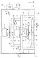
도 1 은 제 1 실시형태에 관련된 노광 장치의 일례를 나타내는 개략 구성도이다.
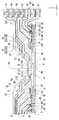
도 2 는 제 1 실시형태에 관련된 종단 광학 소자 및 액침 부재의 근방을 나타내는 단면도이다.
도 3 은 제 1 실시형태에 관련된 액침 부재의 근방을 나타내는 단면도이다.
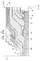
도 4 는 제 2 실시형태에 관련된 액침 부재의 근방을 나타내는 단면도이다.
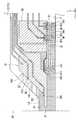
도 5 는 제 3 실시형태에 관련된 액침 부재의 근방을 나타내는 단면도이다.
도 6 은 제 4 실시형태에 관련된 액침 부재의 근방을 나타내는 단면도이다.
도 7 은 제 5 실시형태에 관련된 액침 부재의 근방을 나타내는 단면도이다.
도 8 은 제 6 실시형태에 관련된 액침 부재의 근방을 나타내는 단면도이다.
도 9 는 제 7 실시형태에 관련된 액침 부재의 근방을 나타내는 단면도이다.
도 10 은 마이크로 디바이스의 제조 공정의 일례를 설명하기 위한 플로우 차트이다.1 is a schematic structural view showing an example of an exposure apparatus according to the first embodiment.
2 is a cross-sectional view showing the vicinity of the end optical element and the liquid immersion member related to the first embodiment.
3 is a cross-sectional view showing the vicinity of the liquid immersion member according to the first embodiment.
4 is a cross-sectional view showing the neighborhood of the liquid immersion member according to the second embodiment.
5 is a cross-sectional view showing the neighborhood of the liquid immersion member according to the third embodiment.
6 is a cross-sectional view showing the neighborhood of the liquid immersion member according to the fourth embodiment.
7 is a cross-sectional view showing the neighborhood of the liquid immersion member according to the fifth embodiment.
8 is a cross-sectional view showing the vicinity of the liquid immersion member according to the sixth embodiment.
9 is a cross-sectional view showing the neighborhood of the liquid immersion member according to the seventh embodiment.
10 is a flowchart for explaining an example of a manufacturing process of the microdevice.
이하, 본 발명의 실시형태에 대해 도면을 참조하면서 설명하는데, 본 발명은 이에 한정되지 않는다. 이하의 설명에 있어서는, XYZ 직교 좌표계를 설정하고, 이 XYZ 직교 좌표계를 참조하면서 각 부의 위치 관계에 대해 설명한다. 수평면 내의 소정 방향을 X 축 방향, 수평면 내에 있어서 X 축 방향과 직교하는 방향을 Y 축 방향, X 축 방향 및 Y 축 방향의 각각과 직교하는 방향 (즉 연직 방향) 을 Z 축 방향으로 한다. 또, X 축, Y 축, 및 Z 축 둘레의 회전 (경사) 방향을 각각, θX, θY, 및 θZ 방향으로 한다.Hereinafter, embodiments of the present invention will be described with reference to the drawings, but the present invention is not limited thereto. In the following description, the XYZ orthogonal coordinate system is set, and the positional relationship of each part is described with reference to the XYZ orthogonal coordinate system. The direction orthogonal to the X-axis direction is defined as the Y-axis direction, and the direction perpendicular to each of the X-axis direction and the Y-axis direction (that is, the vertical direction) is defined as the Z-axis direction. The directions of rotation (inclination) about the X axis, the Y axis, and the Z axis are the? X,? Y, and? Z directions, respectively.
<제 1 실시형태>≪ First Embodiment >
제 1 실시형태에 대해 설명한다. 도 1 은, 제 1 실시형태에 관련된 노광 장치 (EX) 의 일례를 나타내는 개략 구성도이다. 본 실시형태의 노광 장치 (EX) 는, 액체 (LQ) 를 통하여 노광광 (EL) 으로 기판 (P) 을 노광하는 액침 노광 장치이다. 본 실시형태에 있어서는, 노광광 (EL) 의 광로의 적어도 일부가 액체 (LQ) 로 채워지도록 액침 공간 (LS) 이 형성된다. 액침 공간 (LS) 은, 액체 (LQ) 로 채워진 부분 (공간, 영역) 이다. 기판 (P) 은, 액침 공간 (LS) 의 액체 (LQ) 를 통하여 노광광 (EL) 에 의해 노광된다. 본 실시형태에 있어서는, 액체 (LQ) 로서 물 (순수) 을 사용한다.The first embodiment will be described. 1 is a schematic structural view showing an example of an exposure apparatus EX according to the first embodiment. The exposure apparatus EX of the present embodiment is an immersion exposure apparatus that exposes the substrate P with the exposure light EL through the liquid LQ. In the present embodiment, the immersion space LS is formed such that at least a part of the optical path of the exposure light EL is filled with the liquid LQ. The immersion space LS is a portion (space, area) filled with the liquid LQ. The substrate P is exposed by the exposure light EL through the liquid LQ in the immersion space LS. In the present embodiment, water (pure water) is used as the liquid LQ.
도 1 에 있어서, 노광 장치 (EX) 는, 마스크 (M) 를 유지하여 이동 가능한 마스크 스테이지 (1) 와, 기판 (P) 을 유지하여 이동 가능한 기판 스테이지 (2) 와, 마스크 스테이지 (1) 및 기판 스테이지 (2) 의 위치를 광학적으로 계측하는 간섭계 시스템 (3) 과, 마스크 (M) 를 노광광 (EL) 으로 조명하는 조명계 (IL) 와, 노광광 (EL) 에 의해 조명된 마스크 (M) 의 패턴 이미지를 기판 (P) 에 투영하는 투영 광학계 (PL) 와, 노광광 (EL) 의 광로의 적어도 일부가 액체 (LQ) 로 채워지도록 액침 공간 (LS) 을 형성 가능한 액침 부재 (4) 와, 적어도 투영 광학계 (PL) 및 기판 스테이지 (2) 를 수용하는 챔버 장치 (5) 와, 적어도 투영 광학계 (PL) 를 지지하는 바디 (6) 와, 노광 장치 (EX) 전체의 동작을 제어하는 제어 장치 (7) 를 구비하고 있다.1, the exposure apparatus EX includes a
마스크 (M) 는, 기판 (P) 에 투영되는 디바이스 패턴이 형성된 레티클을 포함한다. 마스크 (M) 는, 예를 들어 유리판 등의 투명판과, 그 투명판 상에 크롬 등의 차광 재료를 사용하여 형성된 패턴을 갖는 투과형 마스크를 포함한다. 또한, 마스크 (M) 로서 반사형 마스크를 사용할 수도 있다.The mask M includes a reticle in which a device pattern to be projected onto the substrate P is formed. The mask M includes, for example, a transparent plate such as a glass plate and a transmissive mask having a pattern formed by using a light-shielding material such as chromium on the transparent plate. Further, a reflective mask may be used as the mask M.
기판 (P) 은, 디바이스를 제조하기 위한 기판이다. 기판 (P) 은, 예를 들어 반도체 웨이퍼 등의 기재와, 그 기재 상에 형성된 다층막을 포함한다. 다층막은, 적어도 감광막을 포함하는 복수의 막이 적층된 막이다. 감광막은, 감광재로 형성된 막이다. 또, 다층막이, 예를 들어 반사 방지막, 및 감광막을 보호하는 보호막 (탑코트막) 을 포함해도 된다.The substrate P is a substrate for manufacturing a device. The substrate P includes, for example, a substrate such as a semiconductor wafer and a multilayer film formed on the substrate. The multilayer film is a film in which a plurality of films including at least a photosensitive film are laminated. The photosensitive film is a film formed of a photosensitive material. The multilayered film may include, for example, an antireflection film and a protective film (top coat film) for protecting the photoresist film.
챔버 장치 (5) 는, 실질적으로 닫힌 내부 공간 (8) 을 형성하는 챔버 부재 (5A) 와, 내부 공간 (8) 의 환경 (온도, 습도, 클린도, 및 압력 등) 을 제어하는 환경 제어 장치 (5B) 를 갖는다. 기판 스테이지 (2) 는, 내부 공간 (8) 을 이동한다. 제어 장치 (7) 는, 환경 제어 장치 (5A) 를 사용하여, 적어도 기판 스테이지 (2) 에 유지된 기판 (P) 의 노광이 실시되는 공간 (내부 공간 (8)) 의 환경을 제어한다.The
본 실시형태에 있어서는, 내부 공간 (8) 에, 바디 (6) 가 배치된다. 바디 (6) 는, 지지면 (FL) 상에 형성된 제 1 칼럼 (9) 과, 제 1 칼럼 (9) 상에 형성된 제 2 칼럼 (10) 을 갖는다. 제 1 칼럼 (9) 은, 제 1 지지 부재 (11) 와 제 1 지지 부재 (11) 에 방진 장치 (12) 를 개재하여 지지된 제 1 정반 (定盤) (13) 을 갖는다. 제 2 칼럼 (10) 은, 제 1 정반 (13) 상에 형성된 제 2 지지 부재 (14) 와, 제 2 지지 부재 (14) 에 방진 장치 (15) 를 개재하여 지지된 제 2 정반 (16) 을 갖는다. 또, 본 실시형태에 있어서는, 지지면 (FL) 상에, 방진 장치 (17) 를 개재하여, 제 3 정반 (18) 이 배치되어 있다.In the present embodiment, the
조명계 (IL) 는, 소정의 조명 영역 (IR) 에 노광광 (EL) 을 조사한다. 조명 영역 (IR) 은, 조명계 (IL) 로부터 사출되는 노광광 (EL) 이 조사 가능한 위치를 포함한다. 조명계 (IL) 는, 조명 영역 (IR) 에 배치된 마스크 (M) 의 적어도 일부를, 균일한 조도 분포의 노광광 (EL) 으로 조명한다. 조명계 (IL) 로부터 사출되는 노광광 (EL) 으로서, 예를 들어 수은 램프로부터 사출되는 휘선 (g 선, h 선, i 선) 및 KrF 엑시머 레이저광 (파장 248 ㎚) 등의 원자외광 (DUV 광), ArF 엑시머 레이저광 (파장 193 ㎚), 및 F2 레이저광 (파장 157 ㎚) 등의 진공 자외광 (VUV 광) 등이 사용된다. 본 실시형태에 있어서는, 노광광 (EL) 으로서 자외광 (진공 자외광) 인 ArF 엑시머 레이저광을 사용한다.The illumination system IL irradiates the predetermined illumination area IR with exposure light EL. The illumination region IR includes a position at which the exposure light EL emitted from the illumination system IL can be irradiated. The illumination system IL illuminates at least a part of the mask M arranged in the illumination area IR with the exposure light EL of uniform illumination distribution. As the exposure light EL that is emitted from the illumination system IL, for example, light rays (g line, h line, i line) emitted from a mercury lamp and external light (DUV light Vacuum ultraviolet light (VUV light) such as ArF excimer laser light (wavelength 193 nm) and F2 laser light (wavelength 157 nm) are used. In the present embodiment, ArF excimer laser light which is ultraviolet light (vacuum ultraviolet light) is used as the exposure light EL.
마스크 스테이지 (1) 는, 마스크 (M) 를 릴리스가능하게 유지하는 마스크 유지부 (19) 를 갖고, 마스크 (M) 를 유지한 상태에서, 제 2 정반 (16) 의 가이드면 (16G) 상을 이동 가능하다. 마스크 스테이지 (1) 는, 구동 시스템 (20) 의 작동에 의해, 조명 영역 (IR) 에 대해, 마스크 (M) 를 유지하여 이동 가능하다. 구동 시스템 (20) 은, 마스크 스테이지 (1) 에 배치된 가동자 (20A) 와, 제 2 정반 (16) 에 배치된 고정자 (20B) 를 갖는 평면 모터를 포함한다. 마스크 스테이지 (1) 를 이동 가능한 평면 모터는, 예를 들어 미국 특허 제6452292호 명세서에 개시되어 있다. 마스크 스테이지 (1) 는, 구동 시스템 (20) 의 작동에 의해, X 축, Y 축, Z 축, θX, θY, 및 θZ 방향의 6 개의 방향으로 이동 가능하다.The
투영 광학계 (PL) 는, 소정의 투영 영역 (PR) 에 노광광 (EL) 을 조사한다. 투영 광학계 (PL) 는, 투영 영역 (PR) 에 배치된 기판 (P) 의 적어도 일부에, 마스크 (M) 의 패턴 이미지를 소정의 투영 배율로 투영한다. 본 실시형태의 투영 광학계 (PL) 는, 그 투영 배율이 예를 들어 1/4, 1/5, 또는 1/8 등의 축소계이다. 또한, 투영 광학계 (PL) 는 등배계 및 확대계의 어느 것이어도 된다. 본 실시형태에 있어서는, 투영 광학계 (PL) 의 광축 (AX) 은 Z 축과 평행이다. 또, 투영 광학계 (PL) 는, 반사 광학 소자를 포함하지 않는 굴절계, 굴절 광학 소자를 포함하지 않는 반사계, 반사 광학 소자와 굴절 광학 소자를 포함하는 반사 굴절계의 어느 것이어도 된다. 또, 투영 광학계 (PL) 는, 도립상 (倒立像) 과 정립상 (正立像) 의 어느 것을 형성해도 된다.The projection optical system PL irradiates the predetermined projection area PR with exposure light EL. The projection optical system PL projects a pattern image of the mask M onto at least a part of the substrate P disposed in the projection area PR at a predetermined projection magnification. The projection optical system PL of the present embodiment has a projection magnification of, for example, 1/4, 1/5, or 1/8 or the like. Further, the projection optical system PL may be any of an equi-magnification system and an enlargement system. In the present embodiment, the optical axis AX of the projection optical system PL is parallel to the Z axis. The projection optical system PL may be any of a refracting system that does not include a reflective optical element, a reflective system that does not include a refractive optical element, and a reflective refracting system that includes a reflective optical element and a refractive optical element. Further, the projection optical system PL may be either an inverted image or an erect image.
투영 광학계 (PL) 의 복수의 광학 소자는, 유지 부재 (경통) (21) 에 유지되어 있다. 유지 부재 (21) 는, 플랜지 (21F) 를 갖는다. 투영 광학계 (PL) 는, 플랜지 (21F) 를 개재하여, 제 1 정반 (13) 에 지지된다. 또한, 제 1 정반 (13) 과 유지 부재 (21) 사이에 방진 장치를 형성할 수 있다.A plurality of optical elements of the projection optical system PL are held in a holding member (lens barrel) The holding
투영 광학계 (PL) 는, 투영 광학계 (PL) 의 이미지면을 향하여 노광광 (EL) 을 사출하는 사출면 (23) 을 갖는다. 사출면 (23) 은, 투영 광학계 (PL) 의 복수의 광학 소자 중, 투영 광학계 (PL) 의 이미지면에 가장 가까운 종단 광학 소자 (22) 에 배치되어 있다. 투영 영역 (PR) 은, 사출면 (23) 으로부터 사출되는 노광광 (EL) 이 조사 가능한 위치를 포함한다. 본 실시형태에 있어서, 사출면 (23) 은 -Z 방향을 향하고 있고, XY 평면과 평행이다. 또한, -Z 방향을 향하고 있는 사출면 (23) 은, 볼록면이어도 되고, 오목면이어도 된다.The projection optical system PL has an
본 실시형태에 있어서, 종단 광학 소자 (22) 의 광축 (투영 광학계 (PL) 의 이미지면 근방의 광축) (AX) 은, Z 축과 거의 평행이다. 또한, 종단 광학 소자 (22) 와 이웃하는 광학 소자로 규정되는 광축을 종단 광학 소자 (22) 의 광축으로 간주해도 된다. 또, 본 실시형태에 있어서, 투영 광학계 (PL) 의 이미지면은, X 축과 Y 축을 포함하는 XY 평면과 거의 평행이다. 또, 본 실시형태에 있어서, 이미지면은 거의 수평이다. 단, 이미지면은 XY 평면과 평행이 아니어도 되고, 곡면이어도 된다.In this embodiment, the optical axis (optical axis AX) near the image plane of the projection optical system PL is almost parallel to the Z axis of the end
기판 스테이지 (2) 는, 기판 (P) 을 릴리스가능하게 유지하는 기판 유지부 (24) 를 갖고, 제 3 정반 (18) 의 가이드면 (18G) 상을 이동 가능하다. 기판 스테이지 (2) 는, 구동 시스템 (25) 의 작동에 의해, 투영 영역 (PR) 에 대하여, 기판 (P) 을 유지하여 이동 가능하다. 구동 시스템 (25) 은, 기판 스테이지 (2) 에 배치된 가동자 (25A) 와, 제 3 정반 (18) 에 배치된 고정자 (25B) 를 갖는 평면 모터를 포함한다. 기판 스테이지 (2) 를 이동 가능한 평면 모터는, 예를 들어 미국 특허 제6452292호 명세서에 개시되어 있다. 기판 스테이지 (2) 는, 구동 시스템 (25) 의 작동에 의해, X 축, Y 축, Z 축, θX, θY, 및 θZ 방향의 6 개의 방향으로 이동 가능하다.The
기판 스테이지 (2) 는, 기판 유지부 (24) 의 주위에 배치되고, 사출면 (23) 과 대향 가능한 상면 (26) 을 갖는다. 본 실시형태에 있어서, 기판 스테이지 (2) 는, 미국 특허 출원 공개 제2007/0177125호 명세서 등에 개시되어 있는 바와 같은, 기판 유지부 (24) 의 주위의 적어도 일부에 배치되고, 플레이트 부재 (T) 의 하면을 릴리스가능하게 유지하는 플레이트 부재 유지부 (27) 를 갖는다. 본 실시형태에 있어서, 기판 스테이지 (2) 의 상면 (26) 은, 플레이트 부재 (T) 의 상면을 포함한다. 상면 (26) 은 평탄하다. 또한, 플레이트 부재 (T) 가 기판 스테이지 (2) 로부터 릴리스할 수 없어도 된다.The
본 실시형태에 있어서, 기판 유지부 (24) 는, 기판 (P) 의 표면과 XY 평면이 거의 평행이 되도록, 기판 (P) 을 유지할 수 있다. 플레이트 부재 유지부 (27) 는, 플레이트 부재 (T) 의 상면 (26) 과 XY 평면이 거의 평행이 되도록, 플레이트 부재 (T) 를 유지할 수 있다.In the present embodiment, the
간섭계 시스템 (3) 은, XY 평면 내에 있어서의 마스크 스테이지 (1) (마스크 (M)) 의 위치를 광학적으로 계측할 수 있는 제 1 간섭계 유닛 (3A) 과, XY 평면 내에 있어서의 기판 스테이지 (2) (기판 (P)) 의 위치를 광학적으로 계측할 수 있는 제 2 간섭계 유닛 (3B) 을 갖는다. 기판 (P) 의 노광 처리를 실행할 때, 혹은 소정의 계측 처리를 실행할 때, 제어 장치 (7) 는, 간섭계 시스템 (3) 의 계측 결과에 기초하여, 구동 시스템 (20, 25) 을 작동시키고, 마스크 스테이지 (1) (마스크 (M)) 및 기판 스테이지 (2) (기판 (P)) 의 위치 제어를 실행한다.The interferometer system 3 includes a
액침 부재 (4) 는, 노광광 (EL) 의 광로 주위의 적어도 일부에 배치된다. 본 실시형태에 있어서, 액침 부재 (4) 의 적어도 일부는, 종단 광학 소자 (22) 의 주위의 적어도 일부에 배치된다. 본 실시형태에 있어서, 액침 부재 (4) 는, 지지 기구 (28) 에 지지되어 있다. 본 실시형태에 있어서, 지지 기구 (28) 는, 제 1 정반 (13) 에 지지되어 있다. 본 실시형태에 있어서, 액침 부재 (4) 는, 지지 기구 (28) 을 개재하여, 제 1 정반 (13) 에 매달려져 있다.The
본 실시형태의 노광 장치 (EX) 는, 마스크 (M) 와 기판 (P) 을 소정의 주사 방향으로 동기 이동시키면서, 마스크 (M) 의 패턴 이미지를 기판 (P) 에 투영하는 주사형 노광 장치 (소위 스캐닝 스테퍼) 이다. 기판 (P) 의 노광시, 제어 장치 (7) 는, 마스크 스테이지 (1) 및 기판 스테이지 (2) 를 제어하고, 마스크 (M) 및 기판 (P) 을, 광축 (AX) (노광광 (EL) 의 광로) 과 교차하는 XY 평면 내의 소정의 주사 방향으로 이동시킨다. 본 실시형태에 있어서는, 기판 (P) 의 주사 방향 (동기 이동 방향) 을 Y 축 방향으로 하고, 마스크 (M) 의 주사 방향 (동기 이동 방향) 도 Y 축 방향으로 한다. 제어 장치 (7) 는, 기판 (P) 을 투영 광학계 (PL) 의 투영 영역 (PR) 에 대해 Y 축 방향으로 이동시킴과 함께, 그 기판 (P) 의 Y 축 방향으로의 이동과 동기시켜, 조명계 (IL) 의 조명 영역 (IR) 에 대해 마스크 (M) 를 Y 축 방향으로 이동시키면서, 투영 광학계 (PL) 와 기판 (P) 상의 액침 공간 (LS) 의 액체 (LQ) 를 통하여 기판 (P) 에 노광광 (EL) 을 조사한다. 이로써, 마스크 (M) 의 패턴의 이미지가 기판 (P) 에 투영되고, 기판 (P) 은 노광광 (EL) 에 의해 노광된다.The exposure apparatus EX of the present embodiment is a scanning exposure apparatus for projecting a pattern image of a mask M onto a substrate P while synchronously moving the mask M and the substrate P in a predetermined scanning direction Called scanning stepper). The control device 7 controls the
다음으로, 도 2 및 도 3 을 참조하여, 액침 부재 (4) 에 대해 설명한다. 도 2 는, 액침 부재 (4) 의 근방을 나타내는 측단면도, 도 3 은, 도 2 의 일부를 확대한 도면이다.Next, the
본 실시형태에 있어서, 액침 부재 (4) 는, 고리형의 부재이다. 액침 부재 (4) 의 적어도 일부는, 노광광 (EL) 의 일부의 광로 및 종단 광학 소자 (22) 의 주위에 배치되어 있다. 본 실시형태에 있어서, XY 평면 내에 있어서의 액침 부재 (4) 의 외형은, 원형이다. 또한, 액침 부재 (4) 의 외형이, 다른 형상 (예를 들어, 직사각형) 이어도 된다.In this embodiment, the
액침 부재 (4) 는, 사출면 (23) 과 대향하는 위치에 배치된 물체의 표면 (상면) 과 대향 가능한 하면 (下面) (30) 을 갖는다. 액침 부재 (4) 는, 사출면 (23) 과, 사출면 (23) 과 대향하는 위치에 배치된 물체와의 사이의 노광광 (EL) 의 광로 (K) 가 액체 (LQ) 로 채워지도록 액침 공간 (LS) 을 형성한다. 액체 (LQ) 가, 액침 부재 (4) 의 하면 (30) 과 대향하는 물체의 표면 (상면) 과, 액침 부재 (4) 의 하면 (30) 의 적어도 일부와의 사이에 유지되고, 액침 공간 (LS) 의 일부가, 그 물체의 표면과 액침 부재 (4) 의 하면 (30) 사이에 형성된다. 또, 본 실시형태에 있어서는, 액침 공간 (LS) 의 일부가, 물체의 표면과 종단 광학 소자 (22) 사이, 및 종단 광학 소자 (22) 와 액침 부재 (4) 사이에 형성된다. 즉, 본 실시형태에 있어서는, 액침 공간 (LS) 의 액체 (LQ) 는, 액침 부재 (4) 와 물체 사이에 유지되는 액체 (LQ), 종단 광학 소자 (22) 와 물체 사이에 유지되는 액체 (LQ), 및 액침 부재 (4) 와 종단 광학 소자 (22) 사이에 유지되는 액체 (LQ) 를 포함한다.The
본 실시형태에 있어서, 사출면 (23) 과 대향하는 위치로 이동 가능한 물체는, 기판 스테이지 (2) (플레이트 부재 (T)), 및 기판 스테이지 (2) 에 유지된 기판 (P) 중 적어도 일방을 포함한다. 기판 (P) 의 노광 중, 액침 부재 (4) 는, 노광광 (EL) 의 광로 (K) 가 액체 (LQ) 로 채워지도록 액침 공간 (LS) 을 형성한다.In this embodiment, an object movable to a position opposed to the
이하, 간단하므로, 사출면 (23) 및 하면 (30) 과 대향하는 위치에 기판 (P) 이 배치되고, 액침 부재 (4) 와 기판 (P) 사이에 액체 (LQ) 가 유지되어 액침 공간 (LS) 이 형성되는 경우를 예로 들어 설명한다. 또한, 종단 광학 소자 (22) 및 액침 부재 (4) 와 다른 부재 (기판 스테이지 (2) 의 플레이트 부재 (T) 등) 사이에 액침 공간 (LS) 을 형성할 수 있다.The substrate P is disposed at a position opposite to the
본 실시형태에 있어서는, 기판 (P) 에 노광광 (EL) 이 조사되고 있을 때, 투영 영역 (PR) 을 포함하는 기판 (P) 의 표면의 일부 영역이 액체 (LQ) 로 덮이도록 액침 공간 (LS) 이 형성된다. 본 실시형태의 노광 장치 (EX) 는, 국소 액침 방식을 채용한다.In this embodiment, when the substrate P is irradiated with the exposure light EL, the liquid immersion space (the liquid immersion space) is formed so that a part of the surface of the substrate P including the projection region PR is covered with the liquid LQ LS are formed. The exposure apparatus EX of the present embodiment employs a local immersion method.
본 실시형태에 있어서는, 액침 공간 (LS) 의 액체 (LQ) 의 기액 계면 (메니스커스) 은, 액침 부재 (4) 의 하면 (30) 과, 기판 (P) 의 표면 사이에 배치되는 제 1 계면 (LG1) 과, 사출면 (23) 과 상이한 투영 광학계 (PL) 의 측면 (31) 과, 하면 (30) 과 상이한 액침 부재 (4) 의 내면 (32) 사이에 배치되는 제 2 계면 (LG2) 을 포함한다.The meniscus of the liquid LQ in the liquid immersion space LS is formed in such a manner that the meniscus of the liquid LQ in the liquid immersion space LS is held between the
액침 부재 (4) 의 하면 (30) 은, 투영 광학계 (PL) 의 사출면 (23) 으로부터 사출되는 노광광 (EL) 의 광로 (K) 주위의 적어도 일부에 배치된다. 하면 (30) 은, 사출면 (23) 으로부터 사출되는 노광광 (EL) 이 조사 가능한 위치에 배치되는 기판 (P) 의 표면과 대향 가능하다. 사출면 (23) 및 하면 (30) 은, 액침 부재 (4) 의 하방에 배치된 기판 (P) 의 표면과 대향 가능하다. 기판 (P) 의 노광 중 적어도 일부에 있어서, 사출면 (23) 및 하면 (30) 은, 기판 (P) 의 표면과 대향한다.The
투영 광학계 (PL) 의 측면 (31) 은, 사출면 (23) 주위에 배치된 종단 광학 소자 (22) 의 외측면 (31A) 과, 외측면 (31A) 주위에 배치되고, 하방을 향하는 하면 (31B) 을 포함한다. 외측면 (31A) 및 하면 (31B) 은, 노광광 (EL) 이 통과하지 않는 면이다.The
액침 부재 (4) 의 내면 (32) 은, 사출면 (23) 보다 상방에서, 투영 광학계 (PL) 의 측면 (31) 의 적어도 일부와 대향한다. 액침 부재 (4) 의 내면 (32) 은, 외측면 (31A) 과 대향하는 액침 부재 (4) 의 내측면 (32A) 과, 하면 (31B) 과 대향하는 액침 부재 (4) 의 상면 (32B) 을 포함한다. 본 실시형태에 있어서, 계면 (LG2) 은, 외측면 (31A) 과 내측면 (32A) 사이에 배치된다.The
본 실시형태에 있어서, 액침 부재 (4) 는, 적어도 일부가 사출면 (23) 과 대향하도록 배치된 플레이트부 (41) 와, 적어도 일부가 종단 광학 소자 (22) 주위에 배치되는 본체부 (42) 를 갖는다. 하면 (30) 은, 플레이트부 (41) 및 본체부 (42) 에 배치되어 있다. 내측면 (32A) 및 상면 (32B) 은, 본체부 (42) 에 배치되어 있다. 내측면 (32A) 은, 외측면 (31A) 과 간극을 개재하여 대향한다. 상면 (32B) 은, 하면 (31B) 과 간극을 개재하여 대향한다.In this embodiment, the
본 실시형태에 있어서, 상면 (32B) 은, 종단 광학 소자 (22) 의 표면의 적어도 일부와 대향한다. 본 실시형태에 있어서, 종단 광학 소자 (22) 는, 외측면 (31A) 의 주위에 배치된 플랜지부 (22F) 를 갖고, 하면 (31B) 은, 플랜지부 (22F) 의 하면을 포함한다. 또한, 상면 (32B) 이, 투영 광학계 (PL) 의 유지 부재 (21) 의 표면 (하면) 과 대향해도 되고, 종단 광학 소자 (22) 의 표면 및 유지 부재 (21) 의 표면의 양방과 대향해도 된다. 또, 내측면 (32A) 의 적어도 일부가, 유지 부재 (21) 의 일부와 대향해도 되고, 종단 광학 소자 (22) 및 유지 부재 (21) 와 대향해도 된다.In the present embodiment, the
또, 액침 부재 (4) 의 플레이트부 (41) 는, 노광광 (EL) 의 광로 (K) 주위의 적어도 일부에 배치되고, 적어도 일부가 사출면 (23) 과 대향하는 상면 (33) 을 갖는다. 상면 (33) 은, 하면 (30) 의 반대 방향을 향한다.The
액침 부재 (4) (플레이트부 (41)) 는, 사출면 (23) 으로부터 사출된 노광광 (EL) 이 통과 가능한 개구 (34) 를 갖는다. 하면 (30) 및 상면 (33) 은, 개구 (34) 주위에 배치되어 있다. 기판 (P) 의 노광 중, 사출면 (23) 으로부터 사출된 노광광 (EL) 은, 개구 (34) 를 통하여, 기판 (P) 의 표면에 조사된다. 본 실시형태에 있어서, 개구 (34) 는, 기판 (P) 의 주사 방향 (Y 축 방향) 과 교차하는 X 축 방향으로 길다.The liquid immersion member 4 (plate portion 41) has an
본 실시형태에 있어서, 액침 부재 (4) 는, 노광광 (EL) 의 광로 (K) 를 액체 (LQ) 로 채우기 위해, 액체 (LQ) 를 공급하는 액체 공급구 (35) 와, 액체 (LQ) 에 의해 형성된 액침 공간 (LS) 의 주위 공간 (S1) 의 적어도 일부에, 액체 (LQ) 의 비저항값을 변경할 수 있는 물질을 함유하는 가스 (GD) 를 공급하는 가스 공급구 (36) 와, 가스 공급구 (36) 와 다른 위치에 배치되고, 액침 공간 (LS) 의 주위 공간 (S2) 중 적어도 일부에, 액체 (LQ) 의 비저항값을 변경할 수 있는 물질을 함유하는 가스 (GD) 를 공급하는 가스 공급구 (37) 를 구비하고 있다.The
가스 공급구 (36) 는, 액침 부재 (4) 와 기판 (P) 사이의 공간의 적어도 일부에, 가스 (GD) 를 공급한다. 가스 공급구 (36) 는, 액침 부재 (4) 의 하면 (30) 과 기판 (P) 의 표면 사이에 있어서의, 계면 (LG1) 의 주위 공간 (S1) 의 적어도 일부에 가스 (GD) 를 공급한다.The
가스 공급구 (37) 는, 투영 광학계 (PL) 와 액침 부재 (4) 사이의 공간의 적어도 일부에, 가스 (GD) 를 공급한다. 가스 공급구 (37) 는, 투영 광학계 (PL) 의 측면 (31) 과 액침 부재 (4) 의 내면 (32) 사이에 있어서의, 계면 (LG2) 의 주위의 공간 (S2) 중 적어도 일부에 가스 (GD) 를 공급한다. 본 실시형태에 있어서는, 가스 공급구 (36, 37) 로부터 공급되는 가스 (GD) 는, 챔버 장치 (5) (환경 제어 장치 (5B)) 에 의해 제어되는 내부 공간 (8) 의 기체보다, 액체 (LQ) 의 비저항값을 변경하는 (저하시키는) 물질을 많이 포함하고 있다. 즉, 본 실시형태에 있어서는, 가스 공급구 (36, 37) 로부터 가스 (GD) 를 공급함으로써, 액체 (LQ) 의 비저항값을 변경하는 물질의 농도 (비율) 가 내부 공간 (8) 보다 높은 기체 공간 (S1, S2) 을 액침 공간 (LS) 주위의 적어도 일부에 형성한다.The
본 실시형태에 있어서, 액체 (LQ) 의 비저항값을 변경할 수 있는 물질은, 이산화탄소이다. 가스 공급구 (36, 37) 는, 이산화탄소를 함유하는 가스 (탄산 가스) (GD) 를 공급한다.In the present embodiment, the substance capable of changing the specific resistance value of the liquid LQ is carbon dioxide. The
이산화탄소는, 액체 공급구 (35) 로부터 공급되는 액체 (LQ) 에 가용 (可溶) 이다. 또, 이산화탄소는, 액체 (LQ) 의 비저항값을 저하시킬 수 있다.The carbon dioxide is soluble in the liquid (LQ) supplied from the liquid supply port (35). Further, the carbon dioxide can lower the specific resistance value of the liquid LQ.
가스 공급구 (36) 로부터 액침 부재 (4) 의 하면 (30) 과 기판 (P) 의 표면 사이의 공간 (S1) 에 공급된 가스 (GD) 중 적어도 일부는, 계면 (LG1) 에 접촉된다. 계면 (LG1) 에 접촉하도록 공급된 이산화탄소를 함유하는 가스 (GD) 는, 액체 (LQ) 에 용해시킴으로써, 그 액체 (LQ) 의 비저항값을 저하시킨다.At least a part of the gas GD supplied to the space S1 between the
즉, 본 실시형태에 있어서는, 액침 공간 (LS) 의 계면 (LG1) 의 주위의 공간 (S1) 에 공급된 이산화탄소를 함유하는 가스 (GD) 가, 계면 (LG1) 의 근방의 액체 (LQ) 의 일부에 혼입되어, 용해된다. 이로써, 액체 공급구 (35) 로부터 공급되고, 계면 (LG1) 의 근방에 존재하는 액체 (LQ) (순수) 의 일부가, 탄산수로 변화된다. 그 때문에, 그 계면 (LG1) 의 근방의 액체 (LQ) 의 비저항값이 저하된다.That is, in the present embodiment, the gas GD containing the carbon dioxide supplied to the space S1 around the interface LG1 of the immersion space LS is the gas of the liquid LQ in the vicinity of the interface LG1. It is incorporated into a part and dissolved. As a result, a part of the liquid LQ (pure water) supplied from the
이와 같이, 본 실시형태에 있어서는, 공간 (S1) 에 공급된 가스 (GD) 가, 액침 부재 (4) 와 기판 (P) 사이에 있어서, 액침 공간 (LS) 의 액체 (LQ) 의 일부에 용해되고, 그 액체 (LQ) 의 일부의 비저항값을 저하시킨다. 따라서, 계면 (LG1) 의 근방에 있어서, 액체 (LQ) 의 대전이 억제된다.As described above, in the present embodiment, the gas GD supplied to the space S1 dissolves in a part of the liquid LQ in the immersion space LS between the
동일하게, 가스 공급구 (37) 로부터 투영 광학계 (PL) 의 측면 (31) 과 액침 부재 (4) 의 내면 (32) 사이의 공간에 공급된 가스 (GD) 중 적어도 일부는, 계면 (LG2) 에 접촉된다. 계면 (LG2) 에 접촉하도록 공급된 이산화탄소를 함유하는 가스 (GD) 는, 그 계면 (LG2) 의 근방의 액체 (LQ) 에 용해되고, 그 계면 (LG2) 의 근방의 액체 (LQ) 의 비저항값을 저하시킨다. 이로써, 계면 (LG2) 의 근방에 있어서, 액체 (LQ) 의 대전이 억제된다.At least a part of the gas GD supplied to the space between the
또한, 가스 (GD) 는, 이산화탄소 (탄산 가스) 만으로 구성되어 있어도 되고, 예를 들어 이산화탄소와 다른 가스 (클린한 공기 등) 와의 혼합 가스여도 된다.The gas GD may be composed only of carbon dioxide (carbon dioxide gas), or may be a mixed gas of carbon dioxide and another gas (clean air, etc.).
또한, 액체 (LQ) 의 비저항값을 변경할 수 있는 물질이, 이산화탄소가 아니어도 되고, 예를 들어 오존이어도 되며, 수소여도 된다. 그들 물질도, 액체 (LQ) 에 혼입됨으로써, 그 액체 (LQ) 의 비저항값을 저하시킬 수 있다. 또, 가스 (GD) 가, 액체 (LQ) 의 비저항값을 변경 가능한 2 종류 이상의 물질을 포함하고 있어도 되고, 예를 들어 상기 서술한 이산화탄소, 오존, 및 수소 중, 임의의 2 종류 이상의 물질을 포함해도 된다.Further, the substance capable of changing the specific resistance value of the liquid LQ may not be carbon dioxide, for example, ozone or hydrogen. These materials can also be incorporated into the liquid LQ, thereby lowering the specific resistance value of the liquid LQ. The gas GD may include two or more kinds of materials capable of changing the resistivity value of the liquid LQ. For example, the gas GD may contain any two or more kinds of substances selected from the above-mentioned carbon dioxide, ozone, and hydrogen You can.
또, 본 실시형태에 있어서, 액침 부재 (4) 는, 가스 (GD) 중 적어도 일부를 회수하는 가스 회수구 (38) 와, 가스 회수구 (38) 와 다른 위치에 배치되고, 가스 (GD) 중 적어도 일부를 회수하는 가스 회수구 (39) 를 구비하고 있다. 가스 회수구 (38) 는, 액침 부재 (4) 의 하면 (30) 과 기판 (P) 의 표면 사이에 있어서의, 계면 (LG1) 주위의 공간 (S1) 의 가스 (GD) 중 적어도 일부를 회수한다. 가스 회수구 (39) 는, 투영 광학계 (PL) 의 측면 (31) 과 액침 부재 (4) 의 내면 (32) 사이에 있어서의, 계면 (LG2) 주위의 공간 (S2) 의 가스 (GD) 중 적어도 일부를 회수한다.In this embodiment, the
또, 본 실시형태에 있어서, 액침 부재 (4) 는, 액체 (LQ) 의 적어도 일부를 회수하는 액체 회수구 (40) 를 구비하고 있다.In the present embodiment, the
본 실시형태에 있어서, 액체 공급구 (35) 는, 액침 부재 (4) 와 종단 광학 소자 (22) 사이에 액체 (LQ) 를 공급한다. 본 실시형태에 있어서, 액체 공급구 (35) 는, 내측면 (32A) 에 배치되어 있다. 본 실시형태에 있어서, 액체 공급구 (35) 는, 광로 (K) 에 면하도록, 액침 부재 (4) 의 소정 부위에 배치되어 있다. 본 실시형태에 있어서, 액체 공급구 (35) 는, 사출면 (23) 과 상면 (33) 사이에 액체 (LQ) 를 공급한다.In the present embodiment, the
또한, 액체 공급구 (35) 가, 외측면 (31A) 과 대향하도록, 내측면 (32A) 에 배치되고, 외측면 (31A) 과 내측면 (32A) 사이의 공간에 액체 (LQ) 를 공급해도 된다.The
본 실시형태에 있어서, 액체 공급구 (35) 는, 개구 (34) (노광광 (EL) 의 광로 (K)) 에 대해 +Y 측 및 -Y 측의 각각에 배치되어 있다. 또한, 액체 공급구 (35) 가, 개구 (34) (노광광 (EL) 의 광로 (K)) 에 대해 +X 측 및 -X 측의 각각에 배치되어도 된다. 또, 액체 공급구 (35) 의 수는, 2 개에 한정되지 않는다. 액체 공급구 (35) 는, 노광광 (EL) 의 광로 (K) 의 주위에 있어서, 3 지점 이상의 위치에 배치되어도 된다.In the present embodiment, the
액체 공급구 (35) 로부터의 액체 (LQ) 는, 노광광 (EL) 의 광로 (K) 에 공급된다. 이로써, 노광광 (EL) 의 광로 (K) 가 액체 (LQ) 로 채워진다.The liquid LQ from the
본 실시형태에 있어서는, 액체 회수구 (40) 는, 하면 (30) 의 적어도 일부에 배치되어 있다. 본 실시형태에 있어서, 액침 부재 (4) 의 하방에 배치된 기판 (P) 의 표면은, 액체 회수구 (40) 와 대향 가능하다.In this embodiment, the
본 실시형태에 있어서, 액체 회수구 (40) 는, 하면 (30) 에 있어서 광로 (K) (광축 (AX)) 주위의 적어도 일부에 배치되어 있다. 액체 회수구 (40) 는, 하면 (30) 과 대향하는 위치에 배치되는 기판 (P) (물체) 상의 액체 (LQ) 를 회수할 수 있다. 본 실시형태에 있어서, XY 평면 내에 있어서의 액체 회수구 (40) 의 형상은, 원환상 (元環狀) 이다.In this embodiment, the
또한, XY 평면 내에 있어서의 액체 회수구 (40) 의 형상이, 직사각형의 고리형이어도 된다. 또, 액체 회수구 (40) 가, 광로 (K) 주위의 일부에 배치되어 있어도 된다. 예를 들어, 액체 회수구 (40) 가, 광로 (K) (개구 (34)) 에 대해, 기판 (P) 의 주사 방향의 일방측 (+Y 측) 및 타방측 (-Y 측) 에만 배치되어 있어도 되고, 복수의 액체 회수구 (40) 가 하면 (30) 에 있어서 광로 (K) 주위에 소정 간격으로 배치되어 있어도 된다.Further, the shape of the
본 실시형태에 있어서, 액체 회수구 (40) 에는, 다공 부재 (41) 가 배치되어 있다. 다공 부재 (41) 는, 복수의 구멍 (openings 혹은 pores) 을 포함하는 플레이트상의 부재이다. 또한, 다공 부재 (41) 가, 그물형으로 다수의 작은 구멍이 형성된 다공 부재 (41) 인 메시 필터여도 된다. 액체 회수구 (40) 는, 다공 부재 (41) 의 구멍을 통하여, 기판 (P) 상의 액체 (LQ) 를 회수한다.In the present embodiment, a
본 실시형태에 있어서는, 기판 (P) 노광의 적어도 일부에 있어서, 액체 공급구 (35) 에 의한 액체 (LQ) 의 공급 동작과 병행하여, 액체 회수구 (40) 에 의한 액체 (LQ) 의 회수 동작이 실행된다. 기판 (P) 노광의 적어도 일부에 있어서, 액체 공급구 (35) 로부터 사출면 (23) 과 상면 (33) 사이에 공급된 액체 (LQ) 의 적어도 일부는, 개구 (34) 를 통하여, 하면 (30) 과 기판 (P) 의 표면 사이에 공급되고, 노광광 (EL) 의 광로 (K) 가 액체 (LQ) 로 채워진다. 또, 액체 (LQ) 의 일부는, 하면 (30) 과 기판 (P) 의 표면 사이에 유지된다. 액체 공급구 (35) 에 의한 액체 (LQ) 의 공급 동작과 병행하여, 액체 회수구 (40) 에 의한 액체 (LQ) 의 회수 동작이 실행됨으로써, 액침 부재 (4) 와 기판 (P) 사이에 형성되는 액침 공간 (LS) 의 크기 (체적) 가 정해진다. 기판 (P) 은, 사출면 (23) 과 기판 (P) 의 표면 사이의 액체 (LQ) 를 통하여, 사출면 (23) 으로부터의 노광광 (EL) 에 의해 노광된다.In this embodiment, in at least a part of the exposure of the substrate P, in parallel with the supply operation of the liquid LQ by the
가스 공급구 (36) 는, 공간 (S1) 에 면하도록, 액침 부재 (4) 의 소정 부위에 배치되어 있다. 본 실시형태에 있어서, 가스 공급구 (36) 는, 하면 (30) 의 적어도 일부에 배치되어 있다.The
가스 공급구 (36) 는, 광축 (AX) 에 대한 방사 방향에 있어서, 액체 회수구 (40) 의 외측에 배치되어 있다. 가스 공급구 (36) 는, 하면 (30) 에 있어서, 광로 (K) (광축 (AX)) 주위의 적어도 일부에 배치되어 있다. 본 실시형태에 있어서, 가스 공급구 (36) 는, 액체 (LQ) 가 접촉되지 않는 위치에 배치되어 있다. 즉, 가스 공급구 (36) 는, 광축 (AX) 에 대한 방사 방향에 있어서, 계면 (LG1) 의 외측에 배치된다.The
본 실시형태에 있어서, 가스 공급구 (36) 는, 가스 공급구 (36) 에 대향하는 기판 (P) 의 표면을 향해 기체 (GD) 를 공급한다. 또한, 가스 공급구 (36) 가, 광축 (AX) 에 대한 방사 방향에 있어서 내측을 향해 (계면 (LG1) 을 향해) 가스 (GD) 를 공급해도 된다.In this embodiment, the
본 실시형태에 있어서, 가스 공급구 (36) 는, 광로 (K) (광축 (AX)) 주위의 적어도 일부에 배치되어 있다. 본 실시형태에 있어서, XY 평면 내에 있어서의 가스 공급구 (36) 의 형상은, 원환상이다. 본 실시형태에 있어서, 가스 공급구 (36) 는, 노광광 (EL) 의 광로 (K) 를 둘러싸듯이 형성된 슬릿 개구이다. 또한, XY 평면 내에 있어서의 가스 공급구 (36) 의 형상이, 직사각형의 고리형이어도 된다.In this embodiment, the
본 실시형태에 있어서, 하면 (30) 의 적어도 일부에, 오목부 (42) 가 형성되어 있다. 오목부 (42) 는, 하면 (30) 에 대향하는 기판 (P) 의 표면으로부터 멀어지도록 패여 있다. 본 실시형태에 있어서, 가스 공급구 (36) 는, 오목부 (42) 를 규정하는 오목부의 내면에 배치되어 있다.In the present embodiment, the recessed
본 실시형태에 있어서, XY 평면 내에 있어서의 오목부 (42) 의 형상은, 원환상이다. 또한, XY 평면 내에 있어서의 오목부 (42) 의 형상이, 직사각형의 고리형이어도 된다.In the present embodiment, the shape of the
또한, 가스 공급구 (36) 가, 광로 (K) (광축 (AX)) 주위의 일부에 배치되어 있어도 된다. 예를 들어, 복수의 가스 공급구 (36) 가, 하면 (30) 에 있어서 광로 (K) 주위에 소정 간격으로 배치되어 있어도 된다. 이 경우, 복수의 오목부 (42) 를 하면 (30) 에 소정 간격으로 배치하고, 복수의 오목부 (42) 의 일부 또는 전부에 적어도 1 개의 가스 공급구 (36) 를 배치해도 된다.Further, the
또한, 복수의 가스 공급구 (36) 가, 광축 (AX) 에 대한 방사 방향으로 떨어져 배치되어도 된다. 예를 들어, 가스 공급구 (36) 가, 광로 (K) 의 주위에 배치되는 고리형의 제 1 가스 공급구와, 그 제 1 가스 공급구의 외측에 배치된 제 1 가스 공급구와 거의 동심의 제 2 가스 공급구를 포함해도 된다. 이 경우, 그 제 1, 제 2 가스 공급구의 양방이, 오목부 (42) 의 내면에 배치되어도 되고, 제 1 가스 공급구 및 제 2 가스 공급구의 어느 일방이, 오목부 (42) 의 외측의 하면 (30) 에 배치되고, 타방이, 오목부 (42) 의 내면에 배치되어도 된다.Further, the plurality of
또한, 오목부 (42) 를 형성하지 않고, 하면 (30) 에 가스 공급구 (36) 를 배치해도 된다.Further, the
가스 회수구 (38) 는, 공간 (S1) 에 면하도록, 액침 부재 (4) 에 배치되어 있다. 본 실시형태에 있어서, 가스 회수구 (38) 는, 하면 (30) 의 적어도 일부에 배치되어 있다.The
본 실시형태에 있어서, 가스 회수구 (38) 는, 광축 (AX) 에 대한 방사 방향에 있어서, 가스 공급구 (36) 의 외측에 배치되어 있다. 가스 회수구 (38) 는, 하면 (30) 에 있어서, 가스 공급구 (36) 주위의 적어도 일부에 배치되어 있다. 가스 회수구 (38) 는, 계면 (LG1) 주위의 공간 (S1) 의 가스 (GD) 중 적어도 일부를 회수할 수 있다.In this embodiment, the
본 실시형태에 있어서, XY 평면 내에 있어서의 가스 회수구 (38) 의 형상은, 원환상이다. 본 실시형태에 있어서, 가스 회수구 (38) 는, 노광광 (EL) 의 광로 (K) 를 둘러싸듯이 형성된 슬릿 개구이다. 또한, XY 평면 내에 있어서의 가스 회수구 (38) 의 형상이, 직사각형의 고리형이어도 된다.In the present embodiment, the shape of the
본 실시형태에 있어서, 하면 (30) 의 적어도 일부에, 오목부 (43) 가 형성되어 있다. 오목부 (43) 는, 하면 (30) 에 대향하는 기판 (P) 의 표면으로부터 멀어지도록 패여 있다. 오목부 (43) 는, 광로 (K) (광축 (AAX)) 주위에 배치되어 있다. 오목부 (43) 는, 광축 (AX) 에 대한 방사 방향에 있어서, 오목부 (42) 의 외측에 배치되어 있다. 본 실시형태에 있어서, 가스 회수구 (38) 는, 오목부 (43) 를 규정하는 오목부 (43) 의 내면에 배치되어 있다.In the present embodiment, the recessed
본 실시형태에 있어서, XY 평면 내에 있어서의 오목부 (43) 의 형상은, 원환상이다. 또한, XY 평면 내에 있어서의 오목부 (43) 의 형상이, 직사각형의 고리형이어도 된다.In the present embodiment, the shape of the
또한, 가스 회수구 (38) 가, 가스 공급구 (36) 주위의 일부에 배치되어 있어도 된다. 예를 들어, 복수의 가스 회수구 (38) 가, 하면 (30) 에 있어서 광로 (K) (광축 (AX)) 주위에 소정 간격으로 배치되어 있어도 된다. 이 경우, 복수의 오목부 (43) 를, 하면 (30) 에 있어서 광로 (K) 주위에 소정 간격으로 배치하고, 복수의 오목부 (43) 의 각각에 적어도 하나의 가스 회수구 (38) 를 배치해도 된다. 또, 복수의 가스 회수구 (38) 가, 광축 (AX) 에 대한 방사 방향으로 떨어져 배치되어도 된다. 이 경우, 광로 (K) (광축 (AX)) 에 가까운 가스 회수구와, 제 1 가스 회수구보다 광축 (AX) 으로부터 먼 가스 회수구의 양방을 오목부 (43) 의 내면에 배치해도 되고, 어느 일방만을 오목부 (43) 의 내부에 내면에 배치해도 된다.Further, the
본 실시형태에 있어서는, 가스 공급구 (36) 로부터 가스 (GD) 가 공급된 공간 (S1) 의 습도를, 챔버 장치 (5) (환경 제어 장치 (5B)) 에 의해 제어되는 내부 공간 (8) 의 습도보다 높게 하는 가습 시스템 (44) 이 형성되어 있다. 가습 시스템 (44) 은, 액체 (LQ) 의 증기 (GW) 에 의해 가스 (GD) 를 가습한다.The humidity in the
본 실시형태에 있어서, 가습 시스템 (44) 은, 공간 (S1) 에 액체 (LQ) 의 증기 (GW) 를 공급하는 급기구 (45) 를 갖는다. 본 실시형태에 있어서, 급기구 (45) 는, 공간 (S1) 에 면하도록 액침 부재 (4) 의 하면 (30) 에 배치되어 있다.In the present embodiment, the
본 실시형태에 있어서, 챔버 장치 (5) 는, 내부 공간 (8) 을 클린한 공기로 채우고, 급기구 (45) 는, 수증기에 의해 가습된 공기를 공간 (S1) 에 공급한다.In the present embodiment, the
본 실시형태에 있어서, 급기구 (45) 는, 가스 공급구 (36) 의 근방에 배치되어 있다. 본 실시형태에 있어서는, 급기구 (45) 는, 오목부 (42) 의 내면에 배치되어 있다.In the present embodiment, the
본 실시형태에 있어서, XY 평면 내에 있어서의 급기구 (45) 의 형상은, 원환상이다. 본 실시형태에 있어서, 급기구 (45) 는, 노광광 (EL) 의 광로 (K) 를 둘러싸듯이 형성된 슬릿 개구이다. 또한, XY 평면 내에 있어서의 급기구 (45) 의 형상이, 직사각형의 고리형이어도 된다.In the present embodiment, the shape of the
또한, 복수의 급기구 (45) 가, 광축 (AX) 에 대한 방사 방향으로 떨어져 배치되어도 된다. 또, 급기구 (45) 가, 광로 (K) 주위의 일부에 배치되어 있어도 된다. 예를 들어, 급기구 (45) 가, 하면 (30) 에 있어서 광로 (K) 주위에 소정 간격으로 복수 배치되어 있어도 된다. 또, 급기구 (45) 가 오목부 (42) 의 밖의 하면 (30) 에 배치되어 있어도 된다. 또, 복수의 급기구 (45) 의 일부가, 오목부 (42) 에 배치되고, 나머지가 오목부 (42) 의 외측의 하면 (30) 에 배치되어도 된다.Further, a plurality of
가스 공급구 (37) 는, 공간 (S2) 에 면하도록, 액침 부재 (4) 에 배치되어 있다. 본 실시형태에 있어서, 가스 공급구 (37) 는, 내측면 (32A) 의 적어도 일부에 배치되어 있다.The
가스 공급구 (37) 는, 사출면 (23) 의 상방에 배치되어 있다. 가스 공급구 (37) 는, 액체 (LQ) 가 접촉되지 않는 위치에 배치된다. 즉, 가스 공급구 (37) 는, 계면 (LG2) 의 상방에 배치된다.The
본 실시형태에 있어서, 가스 공급구 (37) 는, 가스 공급구 (37) 에 대향하는 종단 광학 소자 (22) 의 외측면 (31A) 을 향해 가스 (GD) 를 공급한다. 또한, 가스 공급구 (37) 가, 하방을 향해 (계면 (LG2) 을 향해) 가스 (GD) 를 공급해도 된다.The
본 실시형태에 있어서, 가스 공급구 (37) 는, 고리형이다. 본 실시형태에 있어서, 가스 공급구 (37) 는, 외측면 (31A) 을 둘러싸듯이 형성된 슬릿 개구이다.In this embodiment, the
또한, 가스 공급구 (37) 가, 광축 (AX) 주위의 일부에 배치되어 있어도 된다. 예를 들어, 복수의 가스 공급구 (37) 가 내측면 (32A) 에 있어서 광축 (AX) 의 주위에 소정 간격으로 배치되어 있어도 된다.Further, the
가스 회수구 (39) 는, 공간 (S2) 에 면하도록, 액침 부재 (4) 에 배치되어 있다. 본 실시형태에 있어서, 가스 회수구 (39) 는, 내측면 (32A) 의 적어도 일부에 배치되어 있다.The
가스 회수구 (39) 는, 가스 공급구 (37) 의 상방에 배치되어 있다. 본 실시형태에 있어서, 가스 회수구 (39) 는 고리형이다. 본 실시형태에 있어서, 가스 회수구 (39) 는, 외측면 (31A) 을 둘러싸듯이 형성된 슬릿 개구이다.The
또한, 가스 회수구 (39) 가, 광로 (K) 주위의 일부에 배치되어 있어도 된다. 예를 들어, 복수의 가스 회수구 (39) 가, 내측면 (32A) 에 있어서 광축 (AX) 주위에 소정 간격으로 배치되어 있어도 된다.Further, the
또한, 가스 공급구 (37) 및 가스 회수구 (39) 가, 상면 (32B) 에 배치되어 있어도 된다. 또, 가스 공급구 (37) 가 내측면 (32A) 에 배치되고, 가스 회수구 (39) 가 상면 (32B) 에 배치되어도 된다.The
도 2 에 나타내는 바와 같이, 액체 공급구 (35) 는 공급 유로를 통하여, 액체 공급 장치 (46) 와 접속되어 있다. 공급 유로는, 액침 부재 (4) 의 내부 유로, 및 그 내부 유로와 액체 공급 장치 (46) 를 접속하는 공급관의 유로를 포함한다. 액체 공급 장치 (46) 는, 클린하고 온도 조정된 액체 (LQ) 를, 액체 공급구 (35) 에 공급한다.2, the
액체 회수구 (40) 는, 회수 유로를 통하여, 액체 회수 장치 (47) 와 접속되어 있다. 본 실시형태에 있어서, 회수 유로는, 액침 부재 (4) 의 내부 유로, 및 그 내부 유로와 액체 회수 장치 (47) 를 접속하는 회수관의 유로를 포함한다. 액체 회수 장치 (47) 는, 진공 시스템 (진공원과 액체 회수구 (40) 의 접속 상태를 제어하는 밸브 등) 을 포함하고, 액체 회수구 (40) 로부터 액체 (LQ) 를 흡인하여 회수할 수 있다.The liquid recovery port (40) is connected to the liquid recovery device (47) through the recovery flow path. In the present embodiment, the recovery flow path includes an internal flow path of the
본 실시형태에 있어서, 제어 장치 (7) 는, 액체 회수 장치 (47) 를 제어하고, 다공 부재 (41) 의 하면측 공간 (다공 부재 (41) 의 하면과 기판 (P) 의 표면 사이의 공간) 으로부터 상면측 공간 (회수 유로) 으로 액체 (LQ) 만이 통과되도록, 다공 부재 (41) 의 상면측과 하면측의 압력차를 제어할 수 있다. 본 실시형태에 있어서, 하면측 공간의 압력은, 분위기에 개방되고, 챔버 장치 (5) 에 의해 제어되고 있다. 제어 장치 (7) 는, 다공 부재 (41) 의 하면측으로부터 상면측으로 액체 (LQ) 만이 통과되도록, 액체 회수 장치 (47) 를 제어하고, 하면측의 압력 에 따라, 상면측의 압력을 조정한다. 즉, 제어 장치 (7) 는, 가스는 다공 부재 (41) 의 구멍을 통과하지 않도록 상면측의 공간의 압력을 조정한다. 다공 부재 (41) 의 일측과 타측의 압력차를 조정하고, 다공 부재 (41) 의 일측으로부터 타측에 액체 (LQ) 만을 통과시키는 기술은, 예를 들어 미국 특허 제7292313호 명세서 등에 개시되어 있다.The control device 7 controls the
또한, 본 실시형태에 있어서, 「분위기」는, 액침 부재 (4) 를 둘러싸는 기체이다. 본 실시형태에 있어서, 액침 부재 (4) 를 둘러싸는 기체는, 챔버 장치 (5) 에 의해 형성되는 내부 공간 (8) 의 기체이다. 본 실시형태에 있어서, 챔버 장치 (5) 는, 환경 제어 장치 (5B) 를 사용하여, 내부 공간 (8) 을 클린한 공기로 채운다. 또, 챔버 장치 (5) 는, 환경 제어 장치 (5B) 를 사용하여, 내부 공간 (8) 을 거의 대기압으로 조정한다. 물론, 내부 공간 (8) 을 대기압보다 높게 설정해도 된다.In the present embodiment, the "atmosphere" is a gas surrounding the
본 실시형태에 있어서, 투영 광학계 (PL) 의 측면 (31) 과 액침 부재 (4) 의 내면 (32) 사이의 공간은, 분위기에 개방되어 있다. 또, 액침 부재 (4) 의 하면 (30) 과 기판 (P) 의 표면 사이의 공간도, 분위기에 개방되어 있다.In this embodiment, the space between the
가스 공급구 (36) 는, 급기 유로를 통하여, 가스 공급 장치 (48) 와 접속되어 있다. 급기 유로는, 액침 부재 (4) 의 내부 유로, 및 그 내부 유로와 가스 공급 장치 (48) 를 접속하는 급기관의 유로를 포함한다. 가스 공급 장치 (48) 는, 클린하고 온도 조정된 기체 (GD) 를, 가스 공급구 (36) 에 공급할 수 있다.The
동일하게, 가스 공급구 (37) 는, 급기 유로를 통하여, 가스 공급 장치 (49) 와 접속되어 있다.Similarly, the
급기구 (45) 는, 공급 유로를 통하여, 가습 장치 (50) 와 접속되어 있다. 공급 유로는, 액침 부재 (4) 의 내부 유로, 및 그 내부 유로와 가습 장치 (50) 를 접속하는 공급관의 유로를 포함한다. 가습 장치 (50) 는, 액체 (LQ) 의 증기 (GW) 를 급기구 (45) 에 공급한다.The air supply mechanism (45) is connected to the humidifying device (50) through a supply flow path. The supply flow path includes an internal flow path of the
가스 회수구 (38) 는, 회수 유로를 통하여, 가스 회수 장치 (51) 와 접속되어 있다. 본 실시형태에 있어서, 회수 유로는, 액침 부재 (4) 의 내부 유로, 및 그 내부 유로와 가스 회수 장치 (51) 를 접속하는 회수관의 유로를 포함한다. 가스 회수 장치 (51) 는, 진공 시스템을 포함하고, 가스 회수구 (38) 로부터 공간 (S1) 의 가스를 흡인하여 회수할 수 있다.The
동일하게, 가스 회수구 (39) 는, 회수 유로를 통하여, 가스 회수 장치 (52) 와 접속되어 있다.Similarly, the
다음으로, 상기 서술한 구성을 갖는 노광 장치 (EX) 를 사용하여 기판 (P) 을 노광하는 방법에 대해 설명한다.Next, a method of exposing the substrate P using the exposure apparatus EX having the above-described configuration will be described.
먼저, 제어 장치 (7) 는, 투영 광학계 (PL) 의 사출면 (23) 및 액침 부재 (4) 의 하면 (30) 과 기판 (P) 의 표면 (혹은 기판 스테이지 (2) 의 상면 (26)) 을 대향시킨다.First, the controller 7 controls the
제어 장치 (7) 는, 사출면 (23) 및 하면 (30) 과 기판 (P) 의 표면을 대향시킨 상태에서, 액체 공급 장치 (46) 로부터 액체 (LQ) 를 송출한다. 또, 제어 장치 (7) 는, 액체 회수 장치 (47) 를 작동시킨다. 액체 공급 장치 (46) 로부터 송출된 액체 (LQ) 는, 액체 공급구 (35) 에 공급된다. 액체 공급구 (35) 는, 사출면 (23) 과 기판 (P) 의 표면 사이의 광로 (K) 가 액체 (LQ) 로 채워지도록, 사출면 (23) 과 상면 (33) 사이에 액체 (LQ) 를 공급한다. 액체 공급구 (35) 로부터 사출면 (23) 과 상면 (33) 사이에 공급된 액체 (LQ) 는, 사출면 (23) 으로부터 사출되는 노광광 (EL) 의 광로 (K) 에 공급된다. 이로써, 노광광 (EL) 의 광로 (K) 는, 액체 (LQ) 로 채워진다.The control device 7 sends out the liquid LQ from the
또, 액체 공급구 (35) 로부터 공급된 액체 (LQ) 의 적어도 일부는, 개구 (34) 를 통하여, 하면 (30) 과 기판 (P) 의 표면 사이에 공급되고, 하면 (30) 과 기판 (P) 의 표면 사이에 유지된다. 이로써, 액체 공급구 (35) 로부터 공급된 액체 (LQ) 에 의해, 사출면 (23) 과 기판 (P) 사이의 노광광 (EL) 의 광로 (K) 가 액체 (LQ) 로 채워지도록, 액침 공간 (LS) 이 형성된다.At least a part of the liquid LQ supplied from the
하면 (30) 과 기판 (P) 의 표면 사이의 액체 (LQ) 의 적어도 일부는, 액체 회수구 (40) 로부터 회수된다. 액체 회수구 (40) 로부터 회수된 액체 (LQ) 는, 액체 회수 장치 (47) 로 회수된다.At least a part of the liquid LQ between the
또, 제어 장치 (7) 는, 가스 공급 장치 (48, 49) 로부터 가스 (GD) 를 송출한다. 또, 제어 장치 (7) 는, 가스 회수 장치 (51, 52) 를 작동시킨다. 또, 제어 장치 (7) 는, 가습 장치 (50) 를 작동시킨다.In addition, the control device 7 sends out the gas GD from the
가스 공급 장치 (48) 로부터 송출된 가스 (GD) 는, 가스 공급구 (36) 로부터, 기판 (P) 상에 형성된 액체 (LQ) 의 액침 공간 (LS) 의 주위의 공간 (S1) 중 적어도 일부에 공급된다. 또, 가습 장치 (50) 로부터 송출된 증기 (GW) 는, 급기구 (45) 로부터, 공간 (S1) 의 적어도 일부에 공급된다. 또, 가스 공급 장치 (49) 로부터 송출된 가스 (GD) 는, 가스 공급구 (37) 로부터, 액체 공간 (LS) 주위의 공간 (S2) 중 적어도 일부에 공급된다.The gas GD discharged from the
제어 장치 (7) 는, 액체 공급구 (35) 에 의한 액체 (LQ) 의 공급 동작과, 액체 회수구 (40) 에 의한 액체 (LQ) 의 회수 동작과, 가스 공급구 (36) 에 의한 가스 (GD) 의 공급 동작과, 급기구 (45) 에 의한 증기 (GW) 의 공급 동작과, 가스 회수구 (38) 에 의한 가스 (GD) 및 증기 (GW) 의 회수 동작과, 가스 공급구 (37) 에 의한 가스 (GD) 의 공급 동작과, 가스 회수구 (39) 에 의한 가스 (GD) 의 회수 동작이 병행하여 실행되도록, 액체 공급 장치 (46), 액체 회수 장치 (47), 가스 공급 장치 (48), 가습 장치 (50), 가스 회수 장치 (51), 가스 공급 장치 (49), 및 가스 회수 장치 (52) 의 각각을 제어한다. 즉, 제어 장치 (7) 는, 액체 공급구 (35) 로부터 공급된 액체 (LQ) 에 의해 액침 공간 (LS) 이 형성된 상태에서, 그 액침 공간 (LS) 주위의 공간 (S1) 에 가스 (GD) 및 증기 (GW) 를 공급함과 함께, 그 공간 (S1) 의 가스 (GD) 및 증기 (GW) 를 회수한다. 또, 제어 장치 (7) 는, 액침 공간 (LS) 이 형성된 상태에서, 그 액침 공간 (LS) 주위의 공간 (S2) 에 가스 (GD) 를 공급함과 함께, 그 공간 (S2) 의 가스 (GD) 를 회수한다.The controller 7 controls the operation of supplying the liquid LQ by the
제어 장치 (7) 는, 액침 공간 (LS) 이 형성된 상태에서, 기판 (P) 의 노광을 개시한다. 제어 장치 (7) 는, 조명계 (IL) 로부터 노광광 (EL) 을 사출하고, 마스크 (M) 를 노광광 (EL) 으로 조명한다. 마스크 (M) 로부터의 노광광 (EL) 은, 투영 광학계 (PL) 의 사출면 (23) 으로부터 사출된다. 제어 장치 (7) 는, 사출면 (23) 과 기판 (P) 의 표면 사이의 액체 (LQ) 를 통하여, 사출면 (23) 으로부터의 노광광 (EL) 으로 기판 (P) 을 노광한다. 이로써, 마스크 (M) 의 패턴의 이미지가 기판 (P) 에 투영되고, 기판 (P) 이 노광광 (EL) 에 의해 노광된다. 기판 (P) 의 노광 중에도, 액체 공급구 (35) 에 의한 액체 (LQ) 의 공급 동작과, 액체 회수구 (40) 에 의한 액체 (LQ) 의 회수 동작과, 가스 공급구 (36) 에 의한 가스 (GD) 의 공급 동작과, 급기구 (45) 에 의한 증기 (GW) 의 공급 동작과, 가스 회수구 (38) 에 의한 가스 (GD) 및 증기 (GW) 의 회수 동작과, 가스 공급구 (37) 에 의한 가스 (GD) 의 공급 동작과, 가스 회수구 (39) 에 의한 가스 (GD) 의 회수 동작이 병행하여 실행된다.The control device 7 starts exposure of the substrate P in a state in which the immersion space LS is formed. The control device 7 irradiates the exposure light EL from the illumination system IL and illuminates the mask M with the exposure light EL. The exposure light EL from the mask M is emitted from the
공간 (S1) 에 가스 (GD) 가 공급됨으로써, 계면 (LG1) 의 근방에 있어서, 액체 (LQ) 의 대전이 억제된다. 또, 그 액체 (LQ) 에 접촉되는 액침 부재 (4) 의 대전, 기판 (P) 의 대전, 및 기판 스테이지 (2) (플레이트 부재 (T)) 의 대전이 억제된다.By supplying the gas GD to the space S1, the charging of the liquid LQ is suppressed in the vicinity of the interface LG1. The charging of the
본 실시형태에 있어서는, 오목부 (42, 43) 가 형성되어 있으므로, 가스 (GD) 가 채워지는 공간 (S1) 을 크게 할 수 있다. 따라서, 공간 (S1) 의 가스 (GD) 는, 액체 (LQ) 에 원활히 용해될 수 있고, 대전을 억제할 수 있다.In the present embodiment, since the
또, 공간 (S2) 에 가스 (GD) 가 공급됨으로써, 계면 (LG2) 의 근방에 있어서, 액체 (LQ) 의 대전이 억제된다. 또, 그 액체 (LQ) 에 접촉되는 액침 부재 (4) 의 대전, 및 종단 광학 소자 (22) 의 대전이 억제된다.In addition, by supplying the gas GD to the space S2, charging of the liquid LQ is suppressed in the vicinity of the interface LG2. Also, the charging of the
또, 공간 (S1) 의 가스 (GD) 는, 가스 회수구 (38) 로부터 회수되므로, 가스 (GD) 가 액침 부재 (4) 주위의 공간 (분위기, 내부 공간 (8)) 에 유출되는 것이 억제된다. 동일하게, 가스 회수구 (39) 에 의해, 공간 (S2) 의 가스 (GD) 가, 액침 부재 (4) 주위의 공간에 유출되는 것이 억제된다.Since the gas GD in the space S1 is recovered from the
또, 본 실시형태에 있어서는, 가스 (GD) 가 공급된 공간 (S1) 에, 증기 (GW) 가 공급된다. 액침 공간 (LS) 주위의 공간 (S1) 을 고습도로 한 상태에서, 가스 (GD) 와 액체 (LQ) 를 접촉시킴으로써, 가스 (GD) (액체 (LQ) 의 비저항값을 변경하는 물질) 는, 액체 (LQ) 에 용해되기 쉬워진다. 따라서, 공간 (S1) 에 증기 (GW) 를 공급함으로써, 액체 (LQ) 에 대한 가스 (GD) 의 용해가 촉진되고, 액체 (LQ) 의 대전을 보다 효과적으로 억제할 수 있다.In the present embodiment, the steam GW is supplied to the space S1 to which the gas GD is supplied. The gas GD (a substance which changes the specific resistance value of the liquid LQ) by bringing the gas GD into contact with the liquid LQ in a state where the space S1 around the liquid immersion space LS is in a high humidity state, And is liable to be dissolved in the liquid LQ. Therefore, by supplying the vapor GW to the space S1, the dissolution of the gas GD to the liquid LQ is promoted, and the charging of the liquid LQ can be suppressed more effectively.
또, 액침 공간 (LS) 주위의 공간 (S1) 을 고습도로 함으로써, 액침 공간 (LS) 의 액체 (LQ) 의 기화를 억제할 수 있다. 따라서, 액체 (LQ) 의 기화열 에 의한 액체 (LQ), 액침 부재 (4), 기판 스테이지 (2) (플레이트 부재 (T)) 의 온도 변화의 발생을 억제할 수 있다.In addition, vaporization of the liquid LQ in the liquid immersion space LS can be suppressed by making the space S1 around the liquid immersion space LS high-humidity. It is possible to suppress the occurrence of temperature changes of the liquid LQ, the
또한, 가스 공급 장치 (48) 가, 가습된 가스 (GD) 를, 가스 공급구 (36) 에 공급해도 된다. 즉, 가스 공급 장치 (48) 가 가습 장치를 구비하고 있어도 된다. 이 경우, 가습 장치 (50) 및 급기구 (45) 를 포함하는 가습 시스템 (44) 을 생략해도 된다. 또, 가스 공급 장치 (49) 가, 가습된 가스 (GD) 를, 가스 공급구 (37) 에 공급해도 된다.Further, the
본 실시형태에 있어서, 제어 장치 (7) 는, 가스 공급구 (36) 로부터 공간 (S1) 에 공급되는 단위 시간 당의 기체 (GD) 의 공급량과 가스 공급구 (37) 로부터 공간 (S2) 에 공급되는 단위 시간 당의 기체 (GD) 의 공급량의 적어도 일방을 조정해도 된다. 예를 들어, 액체 (LQ) 의 대전량을 검출할 수 있는 센서를 형성하고, 그 센서의 검출 결과에 기초하여, 제어 장치 (7) 는, 기체 (GD) 의 공급량을 조정한다. 예를 들어, 액침 부재 (4) 의 적어도 일부에 형성된, 액체 (LQ) 의 대전량을 검출할 수 있는 정전 (靜電) 용량 센서의 검출 결과에 기초하여, 제어 장치 (7) 는, 기체 (GD) 의 공급량을 조정할 수 있다. 기체 (GD) 의 공급량에 따라, 액체 (LQ) 의 비저항값이 변경된다. 예를 들어, 센서의 검출 결과에 기초하여, 액체 (LQ) 의 대전량이 크다고 판단되었을 경우, 제어 장치 (7) 는, 기체 (GD) 의 공급량을 많게 한다. 한편, 액체 (LQ) 의 대전량이 작다고 판단되었을 경우, 제어 장치 (7) 는, 기체 (GD) 의 공급량을 줄인다. 또, 제어 장치 (7) 는, 가스 공급구 (36) 로부터의 가스 (GD) 에 포함되는 이산화탄소의 비율 (농도) 과 가스 공급구 (37) 로부터의 가스 (GD) 에 포함되는 이산화탄소의 비율 (농도) 의 적어도 일방을 조정해도 된다. 이 경우도, 상기 서술한 센서의 결과에 기초하여 조정을 실시할 수 있다. 또, 제어 장치 (7) 는, 급기구 (45) 로부터 공간 (S1) 에 공급되는 단위 시간 당의 증기 (GW) 의 양 (유속) 을 조정해도 된다. 이 경우도, 센서의 검출 결과에 기초하여 조정을 실시할 수 있다.The control device 7 controls the supply amount of the gas GD per unit time supplied from the
액체 공급구 (35) 로부터 공급되는 액체 (LQ) 가, 순수 (초순수) 인 경우, 액체 (LQ) 가 대전될 가능성이 높아진다. 또, 기판 스테이지 (2) (플레이트 부재 (T)) 의 상면 (26), 기판 (P) 의 표면 등, 액체 (LQ) 와 접촉되는 부재의 표면이 절연성인 경우, 그 부재가 대전될 가능성이 높아진다. 예를 들어, 기판 스테이지 (2) 의 상면 (26) 이, 절연성의 발액성 재료 (불소계 재료 등) 로 형성되어 있는 경우, 대전될 가능성이 높아진다. 또, 기판 (P) 의 표면이, 절연성의 탑코트막으로 형성되어 있는 경우에도, 대전될 가능성이 높아진다. 또, 본 실시형태의 노광 장치 (EX) 는, 주사형 노광 장치이고, 액침 공간 (LS) 이 형성되어 있는 상태에서, 기판 (P) (기판 스테이지 (2)) 이 XY 평면 내의 소정 방향으로 이동 됨으로써, 액체 (LQ) 및 액체 (LQ) 에 접촉되는 부재 (기판 (P), 기판 스테이지 (2) 등) 의 적어도 일방이 대전될 가능성이 높아진다.When the liquid LQ supplied from the
본 실시형태에 의하면, 액침 공간 (LS) 주위의 공간 (S1, S2) 에, 액체 (LQ) 의 비저항값을 변경할 수 있는 물질을 함유하는 가스 (GD) 가 공급되므로, 액체 (LQ) 및 그 액체 (LQ) 에 접촉되는 부재의 대전을 억제할 수 있다. 즉, 공급된 가스 (GD) 에 의해, 계면 (LG1, LG2) 의 근방의 액체 (LQ) 가 탄산수로 변화되고, 액체 (LQ) 의 비저항값이 변경되므로, 그 계면 (LG1, LG2) 의 근방에 있어서의 액체 (LQ) 의 대전을 억제할 수 있다. 특히, 계면 (LG1, LG2) 근방의 액체 (LQ) 가 대전되기 쉬운 경우, 본 실시형태는 유효하다.According to the present embodiment, since the gas GD containing the substance capable of changing the resistivity value of the liquid LQ is supplied to the spaces S1 and S2 around the liquid immersion space LS, It is possible to suppress the charging of the member contacting the liquid LQ. That is, the liquid LQ in the vicinity of the interfaces LG1 and LG2 is changed to carbonic acid and the specific resistance value of the liquid LQ is changed by the supplied gas GD, so that the vicinity of the interfaces LG1 and LG2 It is possible to suppress the charging of the liquid LQ in the liquid LQ. Particularly, when the liquid LQ in the vicinity of the interfaces LG1 and LG2 is liable to be charged, the present embodiment is effective.
본 실시형태에 있어서는, 계면 (LG1) 주위의 공간 (S1) 은, 가스 (GD) 로 채워지고, 계면 (LG2) 주위의 공간 (S2) 은, 가스 (GD) 로 채워져 있고, 그 가스 (GD) 로 채워진 공간 (S1, S2) 에 의해, 액침 공간 (LS) 의 액체 (LQ) 와, 챔버 장치 (5) 에 의해 제어되는 내부 공간 (8) 의 기체 (본 실시형태에 있어서는 공기) 와의 접촉이 억제된다.In the present embodiment, the space S1 around the interface LG1 is filled with the gas GD, the space S2 around the interface LG2 is filled with the gas GD, and the gas GD The contact between the liquid LQ in the immersion space LS and the gas (air in the present embodiment) of the
본 실시형태에 있어서는, 액체 공급구 (35) 로부터 공급된 액체 (LQ) 에 의해 형성된 액침 공간 (LS) 주위의 공간 (S1, S2) 에, 액체 (LQ) 의 비저항값을 변경할 수 있는 물질을 함유하는 가스 (GD) 가 공급되므로, 노광광 (EL) 의 광로 (K) 의 액체 (LQ) 의 물성 변화를 억제하면서, 액침 공간 (LS) 의 주연부의 액체 (LQ) 및 그 액체 (LQ) 에 접촉되는 부재의 대전을 억제할 수 있다. 따라서, 기판 (P) 을 양호하게 노광할 수 있다.A material capable of changing the resistivity value of the liquid LQ is formed in the spaces S1 and S2 around the liquid immersion space LS formed by the liquid LQ supplied from the
이상 설명한 바와 같이, 본 실시형태에 의하면, 액침 공간 (LS) 의 액체 (LQ) 의 대전, 및 그 액체 (LQ) 에 접촉되는 부재의 대전을 억제할 수 있다. 따라서, 노광 불량의 발생을 억제할 수 있고, 불량 디바이스의 발생을 억제할 수 있다.As described above, according to the present embodiment, it is possible to suppress the charging of the liquid LQ in the liquid immersion space LS and the charging of the member in contact with the liquid LQ. Therefore, occurrence of defective exposure can be suppressed, and generation of defective devices can be suppressed.
예를 들어, 액체 (LQ) 및 부재 중 적어도 일방이 대전되면, 액체 (LQ) 혹은 부재에 이물질 (파티클) 이 흡착되어, 노광 불량이 발생될 가능성이 있다. 또한, 이물질로는, 예를 들어, 기판 (P) 으로부터 발생되는 이물질 (감광막의 일부가 박리된 것, 탑코트막의 일부가 박리된 것, 반사 방지막의 일부가 박리된 것 등), 혹은 기판 스테이지 (2) 주위의 공중을 부유하는 이물질 등을 생각할 수 있다.For example, if at least one of the liquid LQ and the member is charged, foreign matter (particles) may be adsorbed to the liquid LQ or the member, and exposure failure may occur. The foreign substances may be, for example, a foreign matter (a part of the photoresist film peeled off, a part of the top coat film peeled off, a part of the antireflection film peeled, etc.) generated from the substrate P, (2) Foreign matter floating around the air can be considered.
본 실시형태에 의하면, 액체 (LQ) 및 그 액체 (LQ) 에 접촉되는 부재의 대전이 억제되므로, 액체 (LQ) 및 부재에 대한 이물질의 흡착을 억제할 수 있다. 따라서, 노광 불량의 발생을 억제할 수 있다.According to the present embodiment, since the charging of the liquid LQ and the member in contact with the liquid LQ is suppressed, adsorption of foreign matter to the liquid LQ and the member can be suppressed. Therefore, occurrence of an exposure failure can be suppressed.
<제 2 실시형태>≪ Second Embodiment >
다음으로, 제 2 실시형태에 대해 설명한다. 이하의 설명에 있어서, 상기 서술한 실시형태와 동일 또는 동등한 구성 부분에 대해서는 동일한 부호를 붙이고, 그 설명을 간략 혹은 생략한다.Next, the second embodiment will be described. In the following description, constituent elements which are the same as or equivalent to those in the above-described embodiment are denoted by the same reference numerals, and the description thereof will be simplified or omitted.
도 4 는, 제 2 실시형태에 관련된 액침 부재 (4B) 의 일례를 나타내는 도면이다. 제 2 실시형태는, 제 1 실시형태의 변형예이다. 상기 서술한 제 1 실시형태와 상이한 제 2 실시형태의 특징적인 부분은, 내측면 (32A) 의 적어도 일부에, 오목부 (53, 54) 가 형성되고, 그 오목부 (53) 를 규정하는 오목부 (53) 의 내면에, 가스 (GD) 를 공급하는 가스 급기구 (37B), 및 증기 (GW) 를 공급하는 급기구 (55B) 가 배치되고, 오목부 (54) 를 규정하는 오목부 (54) 의 내면에, 가스 (GD) 및 가스 (GW) 를 회수하는 가스 회수구 (39B) 가 배치되어 있는 점에 있다.4 is a view showing an example of the
도 4 에 있어서, 오목부 (53) 는, 내측면 (32A) 에 대향하는 외측면 (31A) 으로부터 멀어지듯이 패여 있다. 오목부 (53) 는, 외측면 (31A) 주위에 배치되어 있다. 오목부 (54) 는, 오목부 (53) 의 상방에 배치되어 있다. 오목부 (54) 는, 내측면 (32A) 에 대향하는 외측면 (31A) 으로부터 멀어지듯이 패여 있다. 오목부 (54) 는, 외측면 (31A) 의 주위에 배치되어 있다.In Fig. 4, the
가스 공급구 (37B) 는, 오목부 (53) 의 내면에 배치되어 있다. 가스 공급구 (37B) 는, 외측면 (31A) 과 내측면 (32A) 사이의 공간 (S2) 에 가스 (GD) 를 공급한다. 급기구 (55B) 는, 액체 (LQ) 의 증기 (GW) 를 공간 (S2) 에 공급하고, 가스 (GD) 가 공급된 공간 (S2) 의 습도를, 내부 공간 (8) 의 습도보다 높게 한다.The
본 실시형태에 있어서는, 오목부 (53, 54) 가 형성되어 있으므로, 가스 (GD) 가 채워지는 공간 (S2) 을 크게 할 수 있다. 따라서, 공간 (S2) 의 가스 (GD) 는, 액체 (LQ) 에 원활히 용해할 수 있고, 대전을 억제할 수 있다. 또, 공간 (S2) 에 증기 (GW) 가 공급되므로, 액체 (LQ) 에 대한 가스 (GD) 의 용해가 촉진되고, 액체 (LQ) 의 대전을 보다 효과적으로 억제할 수 있다. 또, 액체 (LQ) 의 계면 (LG2) 근방에서의 액체 (LQ) 의 기화가 억제되므로, 액체 (LQ), 종단 광학 소자 (22), 액침 부재 (4B) 의 온도의 변화를 억제할 수 있다.In the present embodiment, since the
또한, 제 2 실시형태에 있어서는, 오목부 (53) 에 가스 공급구 (37B) 와 급기구 (55B) 가 배치되어 있는데, 일방을 오목부 (53) 에 배치하고, 타방을 오목부 (53) 밖의 내측면 (32A) 에 배치해도 된다.In the second embodiment, the
또, 오목부 (53) 를 형성하지 않고, 내측면 (32A) 에 가스 공급구 (37B) 와 급기구 (55B) 를 배치해도 된다. 또, 오목부 (54) 를 형성하지 않고, 내측면 (32A) 에 가스 회수구 (39B) 를 배치해도 된다.It is also possible to dispose the
또, 제 2 실시형태에 있어서도, 가스 공급구 (37B), 가스 회수구 (39B), 및 급기구 (55B) 의 적어도 하나를 액침 부재 (4B) 의 상면 (32B) 에 형성할 수 있다.Also in the second embodiment, at least one of the
<제 3 실시형태>≪ Third Embodiment >
다음으로, 제 3 실시형태에 대해 설명한다. 이하의 설명에 있어서, 상기 서술한 실시형태와 동일 또는 동등한 구성 부분에 대해서는 동일한 부호를 붙이고, 그 설명을 간략 혹은 생략한다.Next, the third embodiment will be described. In the following description, constituent elements which are the same as or equivalent to those in the above-described embodiment are denoted by the same reference numerals, and the description thereof will be simplified or omitted.
도 5 는, 제 3 실시형태에 관련된 액침 부재 (4C) 의 일례를 나타내는 도면이다. 제 3 실시형태는, 제 1 실시형태의 변형예이다. 상기 서술한 제 1 실시형태와 상이한 제 3 실시형태의 특징적인 부분은, 노광광 (EL) 의 광로 (K) 주위의 적어도 일부로서, 광축 (AX) 에 대한 방사 방향에 있어서, 액침 부재 (4C) 의 외측에 배치된 유지 부재 (56) 에 가스 공급구 (36C) 와, 급기구 (45C) 와, 가스 회수구 (38C) 가 배치되어 있는 점에 있다.5 is a view showing an example of the
본 실시형태에 있어서, 유지 부재 (56) 는, 액침 부재 (4C) 의 주위에 배치된 고리형의 부재이다. 유지 부재 (56) 는, 기판 (P) 의 표면과 대향 가능한 하면 (57) 을 갖는다. 본 실시형태에 있어서는, 유지 부재 (56) 의 하면 (57) 과 기판 (P) 의 표면 사이에, 가스 공급구 (36C) 로부터 공급된 가스 (GD) 중 적어도 일부가 유지된다.In the present embodiment, the holding
본 실시형태에 있어서는, 액침 부재 (4C) 에, 노광광 (EL) 의 광로 (K) 를 액체 (LQ) 로 채우기 위해 액체 (LQ) 를 공급하는 액체 공급구 (35C) 와, 액체 (LQ) 를 회수하는 액체 회수구 (40C) (다공 부재 (41C)) 와, 공간 (S2) 에 가스 (GD) 를 공급하는 가스 공급구 (37C) 와, 공간 (S2) 의 가스 (GD) 를 회수하는 가스 회수구 (39C) 가 배치되어 있다.The
본 실시형태에 있어서는, 유지 부재 (56) 의 하면 (57) 에, 공간 (S1) 에 가스 (GD) 를 공급하는 가스 공급구 (36C) 와, 공간 (S1) 에 증기 (GW) 를 공급하는 급기구 (45C) 와, 공간 (S1) 의 가스 (GD) 및 증기 (GW) 를 회수하는 가스 회수구 (38C) 가 배치되어 있다. 가스 공급구 (36C) 및 급기구 (45C) 는, 하면 (57) 에 형성된 오목부 (42C) 의 내면에 배치되고, 가스 회수구 (38C) 는, 하면 (57) 에 형성된 오목부 (43C) 의 내면에 배치되어 있다. 본 실시형태에 있어서, 공간 (S1) 은, 액침 부재 (4C) 의 하면 (30C) 의 적어도 일부, 및 유지 부재 (56) 의 하면 (57) 과 기판 (P) 의 표면 사이의 공간이다.In the present embodiment, the
본 실시형태에 있어서도, 액체 (LQ) 등의 대전을 억제하고, 노광 불량의 발생을 억제할 수 있다.Also in this embodiment, it is possible to suppress the charging of the liquid LQ or the like, and to suppress the occurrence of an exposure failure.
또한, 본 실시형태에 있어서, 가스 공급구 (36C) 및 급기구 (45C) 가, 액침 부재 (4C) 에 배치되고, 가스 회수구 (38C) 가 유지 부재 (56) 에 배치되어도 된다. 즉, 가스 공급구 (36C), 급기구 (45C), 및 가스 회수구 (38C) 의 일부를 유지 부재 (56) 에 배치하고, 나머지를 액침 부재 (4C) 에 배치해도 된다. 또, 가스 공급구 (36C), 급기구 (45C), 및 가스 회수구 (38C) 의 일부를, 또 다른 부재에 배치해도 된다.In the present embodiment, the
또, 제 3 실시형태에 있어서도, 가스 공급구 (36C) 와 급기구 (45C) 의 일방을 오목부 (42C) 내에 배치하고, 타방을 유지 부재 (56) 의 하면 (57) 에 배치해도 되고, 오목부 (42C) 를 형성하지 않고, 가스 공급구 (36C) 와 급기구 (45C) 의 양방을 하면 (57) 에 형성해도 된다. 또, 제 3 실시형태에 있어서도, 오목부 (43C) 를 형성하지 않고, 하면 (57) 에 가스 회수구 (38C) 를 형성해도 된다. 또, 제 3 실시형태에 있어서도, 가스 공급구 (36C) 로부터 가습된 가스 (GD) 를 공급하고, 급기구 (45C) 를 생략해도 된다. 또, 제 3 실시형태에 있어서도, 공간 (S2) 에 액체 (LQ) 의 증기를 공급해도 되고, 가스 공급구 (37C) 로부터 가습된 가스 (GD) 를 공급해도 된다.Also in the third embodiment, one of the
또한, 상기 서술한 제 1 ∼ 제 3 실시형태에 있어서는, 증기 (GW) 가, 액체 (LQ) 의 증기에 의해 가스 (GD) 를 가습하는 경우를 예로 들어 설명했는데, 액체 (LQ) 와 상이한 액체의 증기에 의해, 가스 (GD) 를 가습해도 된다.In the first to third embodiments described above, the case where the vapor (GW) humidifies the gas (GD) by the vapor of the liquid (LQ) has been described as an example. However, The gas (GD) may be humidified by the vapor of the gas.
또, 상기 서술한 제 1 ∼ 제 3 실시형태에 있어서는, 가스 공급구로부터 공간 (S1) 에 공급되는 가스 (GD) 와 가스 공급구로부터 공간 (S2) 에 공급되는 가스 (GD) 는 동일했는데, 상이해도 된다. 예를 들어, 공간 (S1) 에 공급되는 가스 (GD) 는, 액체 (LQ) 의 비저항값을 변경하는 물질로서 이산화탄소를 함유하고, 공간 (S2) 에 공급되는 가스 (GD) 가 액체 (LQ) 의 비저항값을 변경하는 물질로서 수소를 함유하고 있어도 된다. 혹은, 공간 (S1) 에 공급되는 가스 (GD) 와, 공간 (S2) 에 공급되는 가스 (GD) 에서, 액체 (LQ) 의 비저항값을 변경하는 물질의 농도 (비율) 가 상이해도 된다.In the first to third embodiments described above, the gas GD supplied from the gas supply port to the space S1 and the gas GD supplied from the gas supply port to the space S2 are the same, . For example, the gas GD supplied to the space S1 contains carbon dioxide as a substance for changing the specific resistance value of the liquid LQ, and the gas GD supplied to the space S2 is a liquid LQ, Hydrogen may be contained as a material for changing the specific resistance value of the hydrogen-containing gas. Alternatively, the concentration (ratio) of the substance for changing the resistivity value of the liquid LQ may be different between the gas GD supplied to the space S1 and the gas GD supplied to the space S2.
또, 상기 서술한 제 1 ∼ 제 3 실시형태에 있어서, 액체 (LQ) 의 비저항값을 변경하는 물질을 포함하는 가스의 공급을, 공간 (S1) 과 공간 (S2) 의 어느 일방에만 실행해도 된다. 또, 상기 서술한 제 1 ∼ 제 3 실시형태에 있어서, 급기구로부터 증기 (GW) 를 공급함으로써, 및/또는 가스 공급구로부터 가습된 가스 (GD) 를 공급함으로써, 공간 (S1) 의 적어도 일부를 가습하고 있는데, 가습하지 않아도 된다. 또, 상기 서술한 제 1 ∼ 제 3 실시형태에 있어서, 공간 (S1) 으로부터 기체를 회수하는 가스 회수구와 공간 (S2) 으로부터 기체를 회수하는 가스 회수구 중 적어도 일방을 생략해도 된다.In the first to third embodiments described above, the supply of the gas containing the substance for changing the resistivity value of the liquid LQ may be performed only in one of the space S1 and the space S2 . In the first to third embodiments described above, at least a part of the space S1 is formed by supplying steam (GW) from the air supply mechanism and / or supplying the gas (GD) , But do not need to humidify. In the first to third embodiments described above, at least one of the gas recovery port for recovering the gas from the space S1 and the gas recovery port for recovering the gas from the space S2 may be omitted.
<제 4 실시형태>≪ Fourth Embodiment &
다음으로, 제 4 실시형태에 대해 설명한다. 이하의 설명에 있어서, 상기 서술한 실시형태와 동일 또는 동등한 구성 부분에 대해서는 동일한 부호를 붙이고, 그 설명을 간략 혹은 생략한다.Next, the fourth embodiment will be described. In the following description, constituent elements which are the same as or equivalent to those in the above-described embodiment are denoted by the same reference numerals, and the description thereof will be simplified or omitted.
도 6 은, 제 4 실시형태에 관련된 액침 부재 (4D) 의 일례를 나타내는 도면이다. 도 6 에 있어서, 액침 부재 (4D) 는, 사출면 (23) 으로부터 사출되는 노광광 (EL) 의 광로 (K) 를 제 1 비저항값을 갖는 제 1 액체 (LQ1) 로 채우기 위해 제 1 액체 (LQ1) 를 공급하는 제 1 공급구 (35D) 와, 제 1 액체 (LQ1) 에 의해 형성된 액침 공간 (LS1) 주위의 공간 (S11) 중 적어도 일부에, 제 1 액체 (LQ1) 와는 상이한 비저항값을 갖는 제 2 액체 (LQ2) 를 공급하는 제 2 공급구 (36D) 를 구비하고 있다. 본 실시형태에 있어서, 제 2 액체 (LQ2) 는, 제 1 액체 (LQ1) 보다 낮은 비저항값을 갖는다.Fig. 6 is a view showing an example of the
상기 서술한 제 1 실시형태의 액침 부재 (4) 와 동일하게, 본 실시형태에 관련된 액침 부재 (4D) 는, 광로 (K) 주위의 적어도 일부에 배치된다. 액침 공간 (LS1) 의 일부는, 액침 부재 (4D) 의 하면 (30D) 에 대향하는 기판 (P) 과, 액침 부재 (4D) 의 하면 (30D) 사이에 형성된다.Like the
제 1 공급구 (35D) 는, 사출면 (23) 과 상면 (33) 사이에 제 1 액체 (LQ1) 를 공급한다. 본 실시형태에 있어서, 제 1 액체 (LQ1) 는, 물 (순수) 이다.The
제 2 공급구 (36D) 는, 액침 부재 (4D) 의 하면 (30D) 에 배치되어 있다. 제 2 공급구 (36D) 는, 공간 (S11) 에 제 2 액체 (LQ2) 를 공급한다. 본 실시형태에 있어서, 제 2 액체 (LQ2) 는, 제 1 액체 (LQ1) 를 포함한다. 즉, 제 2 액체 (LQ2) 의 주성분은, 제 1 액체 (LQ1) (물) 이다.The
본 실시형태에 있어서, 제 2 액체 (LQ2) 는, 제 1 액체 (LQ1) 의 비저항값을 저하시키는 물질을 제 1 액체 (LQ1) 에 용해시킴으로써 (첨가함으로써) 형성된다. 본 실시형태에 있어서, 그 물질은 이산화탄소이다. 즉, 제 2 액체 (LQ2) 는, 이산화탄소를 제 1 액체 (LQ1) (물) 에 용해시킴으로써 형성된 탄산수이다.In the present embodiment, the second liquid LQ2 is formed by dissolving (adding) a substance that lowers the specific resistance value of the first liquid LQ1 in the first liquid LQ1. In the present embodiment, the substance is carbon dioxide. That is, the second liquid LQ2 is carbonated water formed by dissolving carbon dioxide in the first liquid LQ1 (water).
또한, 제 2 액체 (LQ2) 가, 오존을 함유해도 되고, 수소를 함유해도 된다. 즉, 제 2 액체 (LQ2) 가, 오존을 물에 용해시킨 오존수여도 되고, 수소를 물에 용해시킨 수소수여도 된다. 오존수, 혹은 수소수여도, 제 1 액체 (LQ1) 의 비저항값을 저하시킬 수 있다.Further, the second liquid LQ2 may contain ozone or contain hydrogen. That is, the second liquid (LQ2) may be supplied with ozone in which ozone is dissolved in water, and hydrogen may be dissolved in water to give hydrogen. The ozone water or the degree of hydrogen addition and the specific resistance value of the first liquid LQ1 can be lowered.
또, 액침 부재 (4D) 는, 하면 (30D) 에 배치되고, 기판 (P) 상의 제 1 액체 (LQ1) 의 적어도 일부를 회수하는 제 1 회수구 (40D) 를 구비하고 있다. 제 1 회수구 (40D) 에는, 다공 부재 (41D) 가 배치된다. 액침 부재 (4D) 의 제 1 회수구 (40D) 는, 상기 서술한 제 1 실시형태의 액침 부재 (4) 의 액체 회수구 (40) 와 거의 동일한 구성이기 때문에, 상세한 설명은 생략한다.The
제 2 공급구 (36D) 는, 광축 (AX) 에 대한 방사 방향에 있어서, 제 1 회수구 (40D) 의 외측에 배치되어 있다. 본 실시형태에 있어서, XY 평면 내에 있어서의 제 2 공급구 (36D) 의 형상은, 고리형이다. 제 2 공급구 (36D) 는, 제 1 회수구 (40D) 를 둘러싸듯이 배치되어 있다. 또한, 복수의 제 2 공급구 (36D) 가, 하면 (30D) 에 있어서 광로 (K) 주위에 소정 간격으로 배치되어 있어도 된다.The
또, 액침 부재 (4D) 는, 하면 (30D) 에 배치되고, 기판 (P) 상의 제 2 액체 (LQ2) 의 적어도 일부를 회수하는 제 2 회수구 (58D) 를 구비하고 있다. 제 2 회수구 (58D) 는, 광축 (AX) 에 대한 방사 방향에 있어서, 제 2 공급구 (36D) 의 외측에 배치되어 있다. 제 2 회수구 (58D) 에는, 다공 부재 (59D) 가 배치되어 있다. 제 1 회수구 (40D) 와 동일하게, 제 2 회수구 (58D) 는, 다공 부재 (59) 의 구멍을 통하여, 액체만을 회수하고 가스는 회수하지 않는다.The
또, 액침 부재 (4D) 는, 내측면 (32A) 에 배치되고, 종단 광학 소자 (22) 와 액침 부재 (4D) 사이의 공간 (S2) 에, 제 1 액체 (LQ1) 의 비저항값을 변경할 수 있는 물질을 함유하는 가스 (GD) 를 공급할 수 있는 가스 공급구 (37D) 와, 공간 (S2) 의 가스 (GD) 를 회수할 수 있는 가스 회수구 (39D) 를 구비하고 있다. 액침 부재 (4D) 의 가스 공급구 (37D), 및 가스 회수구 (39D) 는, 상기 서술한 제 1 실시형태의 액침 부재 (4) 의 가스 공급구 (37), 및 가스 회수구 (39D) 와 거의 동일한 구성이기 때문에, 상세한 설명은 생략한다.The
다음으로, 상기 서술한 구성을 갖는 노광 장치 (EX) 를 사용하여 기판 (P) 을 노광하는 방법에 대해 설명한다.Next, a method of exposing the substrate P using the exposure apparatus EX having the above-described configuration will be described.
제어 장치 (7) 는, 사출면 (23) 및 하면 (30D) 과 기판 (P) 의 표면을 대향시킨 상태에서, 제 1 공급구 (35D) 에 의한 제 1 액체 (LQ1) 의 공급 동작을 실시함과 함께, 제 1 회수구 (40D) 에 의한 액체의 회수 동작을 실시한다. 제 1 공급구 (35D) 는, 노광광 (EL) 의 광로 (K) 에 제 1 액체 (LQ1) 를 공급한다. 하면 (30D) 과 기판 (P) 의 표면 사이의 제 1 액체 (LQ1) 의 적어도 일부는, 제 1 회수구 (40D) 로부터 회수된다. 제 1 공급구 (35D) 로부터 공급된 제 1 액체 (LQ1) 에 의해, 사출면 (23) 과 기판 (P) 의 표면 사이의 노광광 (EL) 의 광로 (K) 가 제 1 액체 (LQ1) 로 채워지도록, 액침 공간 (LS1) 이 형성된다.The control device 7 performs the supply operation of the first liquid LQ1 by the
또, 제어 장치 (7) 는, 가스 공급구 (37D) 에 의한 공간 (S2) 에 대한 가스 (GD) 의 공급 동작을 실시함과 함께, 가스 회수구 (39D) 에 의한 공간 (S2) 의 가스 (GD) 의 회수 동작을 실시한다. 이로써, 공간 (S2) 이 가스 (GD) 로 채워지고, 가스 (GD) 는, 제 1 액체 (LQ1) 의 계면 (LG2) 에 접촉된다.The control device 7 performs the operation of supplying the gas GD to the space S2 by the
또, 제어 장치 (7) 는, 제 2 공급구 (36D) 에 의한 공간 (S11) 에 대한 제 2 액체 (LQ2) 의 공급 동작을 실시함과 함께, 제 2 회수구 (58D) 에 의한 공간 (S11) 의 제 2 액체 (LQ2) 의 회수 동작을 실시한다. 제 2 공급구 (36D) 로부터 공간 (S11) 에 공급된 제 2 액체 (LQ2) 의 적어도 일부는, 제 1 회수구 (40D) 로부터 회수된다. 또, 제 2 공급구 (36D) 로부터 공간 (S11) 에 공급된 제 2 액체 (LQ2) 의 적어도 일부는, 제 2 회수구 (58D) 로부터 회수된다. 즉, 본 실시형태에 있어서는, 제 1 회수구 (40D) 는, 기판 (P) 상의 제 1 액체 (LQ1) 및 제 2 액체 (LQ2) 를 회수하고, 제 2 회수구 (58D) 는, 기판 (P) 상의 제 2 액체 (LQ2) 를 주로 회수한다.The control device 7 performs the operation of supplying the second liquid LQ2 to the space S11 by the
이로써, 공간 (S11) 이 제 2 액체 (LQ2) 로 채워지고, 제 2 공급구 (36D) 로부터 공간 (S11) 에 공급된 제 2 액체 (LQ2) 는, 액침 공간 (LS1) 의 제 1 액체 (LQ1) 의 계면 (LG1) 에 접촉된다.Thereby, the space S11 is filled with the second liquid LQ2, and the second liquid LQ2 supplied from the
제어 장치 (7) 는, 액침 공간 (LS1) 이 형성된 상태에서, 기판 (P) 의 노광을 개시한다. 제어 장치 (7) 는, 사출면 (23) 과 기판 (P) 의 표면 사이의 제 1 액체 (LQ1) 를 통하여, 사출면 (23) 으로부터의 노광광 (EL) 으로 기판 (P) 을 노광한다.The control device 7 starts exposure of the substrate P in a state in which the immersion space LS1 is formed. The control device 7 exposes the substrate P with the exposure light EL from the
기판 (P) 의 노광 중에도, 제 1 공급구 (35D) 에 의한 제 1 액체 (LQ1) 의 공급 동작과, 제 2 공급구 (36D) 에 의한 제 2 액체 (LQ2) 의 공급 동작과, 제 1 회수구 (40D) 에 의한 제 1, 제 2 액체 (LQ1, LQ2) 의 회수 동작과, 제 2 회수구 (58D) 에 의한 제 2 액체 (LQ2) 의 회수 동작과, 가스 공급구 (37D) 에 의한 가스 (GD) 의 공급 동작과, 가스 회수구 (39D) 에 의한 가스 (GD) 의 회수 동작이 병행하여 실행된다.During the exposure of the substrate P, the supply operation of the first liquid LQ1 by the
본 실시형태에 있어서는, 제 1 액체 (LQ1) 에 의해 형성된 액침 공간 (LS1) 의 주위의 공간 (S1) 은, 비저항값이 낮은 제 2 액체 (LQ2) 로 채워지고, 그 제 2 액체 (LQ2) 로 채워진 공간 (S11) 에 의해, 액침 공간 (LS1) 의 제 1 액체 (LQ1) 와, 챔버 장치 (5) 에 의해 제어되는 내부 공간 (8) 의 기체 (본 실시형태에 있어서는 공기) 와의 접촉이 억제된다.In the present embodiment, the space S1 around the liquid immersion space LS1 formed by the first liquid LQ1 is filled with the second liquid LQ2 having a low specific resistance value, and the second liquid LQ2 is filled with the second liquid LQ2. The contact between the first liquid LQ1 of the immersion space LS1 and the substrate (air in this embodiment) of the
본 실시형태에 있어서는, 공간 (S11) 에, 제 1 액체 (LQ1) 보다 낮은 비저항값을 갖고, 계면 (LG1) 근방의 제 1 액체 (LQ1) 와 서로 섞여, 그 계면 (LG1) 근방에 있어서의 제 1 액체 (LQ1) 의 비저항값을 저하시킬 수 있는 제 2 액체 (LQ2) 가 공급되므로, 제 1 액체 (LQ1) 의 대전이 억제된다. 또, 그 제 1 액체 (LQ1) 에 접촉되는 액침 부재 (4) 의 대전, 기판 (P) 의 대전, 및 기판 스테이지 (2) (플레이트 부재 (T)) 의 대전이 억제된다.In the present embodiment, the first liquid LQ1 has a specific resistance value lower than that of the first liquid LQ1 in the space S11 and is mixed with the first liquid LQ1 in the vicinity of the interface LG1, Since the second liquid LQ2 capable of lowering the specific resistance value of the first liquid LQ1 is supplied, the charging of the first liquid LQ1 is suppressed. The charging of the
<제 5 실시형태>≪
다음으로, 제 5 실시형태에 대해 설명한다. 이하의 설명에 있어서, 상기 서술한 실시형태와 동일 또는 동등한 구성 부분에 대해서는 동일한 부호를 붙이고, 그 설명을 간략 혹은 생략한다.Next, the fifth embodiment will be described. In the following description, constituent elements which are the same as or equivalent to those in the above-described embodiment are denoted by the same reference numerals, and the description thereof will be simplified or omitted.
도 7 은, 제 5 실시형태에 관련된 액침 부재 (4E) 의 일례를 나타내는 도면이다. 제 5 실시형태에 관련된 액침 부재 (4E) 는, 상기 서술한 제 4 실시형태에 관련된 액침 부재 (4D) 의 변형예이다. 제 4 실시형태에 관련된 액침 부재 (4D) 와 상이한 제 5 실시형태에 관련된 액침 부재 (4E) 의 특징적인 부분은, 광축 (AX) 에 대한 방사 방향에 있어서, 제 2 액체 (LQ2) 를 공급하는 제 2 공급구 (36E) 가, 제 1 회수구 (40E) 의 내측에 배치되어 있는 점에 있다. 또, 본 실시형태의 액침 부재 (4E) 에 있어서는, 제 2 회수구 (58D) 가 생략되어 있다.7 is a view showing an example of the
본 실시형태에 있어서, 제 2 공급구 (36E) 는, 액침 부재 (4E) 의 하면 (30E) 에 있어서 광로 (K) 의 주위에 배치되어 있다. 즉, 제 2 공급구 (36E) 의 형상은, 고리형이다. 또한, 복수의 제 2 공급구 (36E) 가, 하면 (30E) 에 있어서 광로 (K) 의 주위에 소정 간격으로 배치되어 있어도 된다.In the present embodiment, the
또, 액침 부재 (4E) 는, 공간 (S2) 에 가스 (GD) 를 공급하는 가스 공급구 (37E) 와, 공간 (S2) 의 가스 (GD) 를 회수하는 가스 회수구 (39E) 를 갖는다. 액침 부재 (4E) 의 가스 공급구 (37E), 및 가스 회수구 (39E) 는, 상기 서술한 제 1 실시형태의 액침 부재 (4) 의 가스 공급구 (37), 및 가스 회수구 (39D) 와 거의 동일한 구성이기 때문에, 상세한 설명은 생략한다.The
본 실시형태에 있어서는, 광로 (K) 가, 제 1 액체 (LQ1) 에 의해 형성되고, 액침 부재 (4E) 와 기판 (P) 사이에 있어서의 계면 (LG11) 을 포함하는 액침 공간 (LS2) 의 주연부가, 제 1 공급구 (35E) 로부터의 제 1 액체 (LQ1) 와 제 2 공급구 (36E) 로부터의 제 2 액체 (LQ2) 에 의해 형성된다. 제 1 회수구 (40E) 는, 다공 부재 (41E) 를 통하여, 제 1 액체 (LQ1) 및 제 2 액체 (LQ2) 의 양방을 회수한다.The optical path K is formed in the liquid immersion space LS2 including the interface LG11 between the
본 실시형태에 있어서는, 계면 (LG11) 의 근방에서, 제 1 액체 (LQ1) 보다 낮은 비저항값의 제 2 액체 (LQ2) 가 공급되고 있으므로, 계면 (LG11) 의 근방에 있어서의 액침 공간 (LS) 의 액체의 대전을 효과적으로 억제할 수 있다.Since the second liquid LQ2 having a lower specific resistance value than the first liquid LQ1 is supplied in the vicinity of the interface LG11 in this embodiment, the liquid immersion space LS in the vicinity of the interface LG11, It is possible to effectively suppress the charging of the liquid of the liquid.
또한, 본 실시형태에 있어서, 광축 (AX) 에 대한 방사 방향에 있어서, 제 1 회수구 (40E) 의 외측에, 제 1 회수구 (40) 로부터 떨어져 배치된 제 2 회수구를, 액침 부재 (4E) 의 하면 (30E) 에 설치해도 된다.In the present embodiment, a second collection port disposed away from the
또, 본 실시형태에 있어서, 광축 (AX) 에 대한 방사 방향에 있어서, 제 1 회수구 (40E) 의 외측에 제 2 액체 (LQ2) 의 증기를 공급하는 급기구를 형성하고, 상기 서술한 제 1 ∼ 제 3 실시형태와 동일하게, 액침 공간 (LS2) 주위의 적어도 일부에, 내부 공간 (8) 보다 고습도인 공간을 형성해도 된다.In the present embodiment, a supply mechanism for supplying the vapor of the second liquid LQ2 to the outside of the
<제 6 실시형태>≪ Sixth Embodiment &
다음으로, 제 6 실시형태에 대해 설명한다. 이하의 설명에 있어서, 상기 서술한 실시형태와 동일 또는 동등한 구성 부분에 대해서는 동일한 부호를 붙이고, 그 설명을 간략 혹은 생략한다.Next, a sixth embodiment will be described. In the following description, constituent elements which are the same as or equivalent to those in the above-described embodiment are denoted by the same reference numerals, and the description thereof will be simplified or omitted.
도 8 은, 제 6 실시형태에 관련된 액침 부재 (4F) 의 일례를 나타내는 도면이다. 제 6 실시형태는, 제 4 실시형태의 변형예이다. 상기 서술한 제 4 실시형태와 상이한 제 6 실시형태의 특징적인 부분은, 노광광 (EL) 의 광로 (K) 의 주위의 적어도 일부로서, 광축 (AX) 에 대한 방사 방향에 있어서, 액침 부재 (4F) 의 외측에 배치된 유지 부재 (56F) 에 제 2 공급구 (36F), 및 제 2 회수구 (58F) (다공 부재 (59F)) 가 배치되어 있는 점에 있다.8 is a view showing an example of the
본 실시형태에 있어서, 유지 부재 (56F) 는, 액침 부재 (4F) 의 주위에 배치된 고리형의 부재이다. 유지 부재 (56F) 는, 기판 (P) 의 표면과 대향 가능한 하면 (57F) 을 갖는다. 본 실시형태에 있어서는, 유지 부재 (56F) 의 하면 (57F) 과 기판 (P) 의 표면 사이에, 제 2 액체 (LQ2) 의 적어도 일부가 유지된다.In the present embodiment, the holding
본 실시형태에 있어서는, 액침 부재 (4F) 에, 광로 (K) 에 제 1 액체 (LQ1) 를 공급하는 제 1 공급구 (35F) 와, 다공 부재 (41F) 가 배치되고, 기판 (P) 상의 액체를 회수하는 제 1 회수구 (40F) 와, 공간 (S2) 에 가스 (GD) 를 공급하는 가스 공급구 (37F) 와, 공간 (S2) 의 가스 (GD) 를 회수하는 가스 회수구 (39F) 가 배치되어 있다.In this embodiment, the
본 실시형태에 있어서는, 유지 부재 (56F) 의 하면 (57F) 에, 공간 (S11) 에 제 2 액체 (LQ2) 를 공급하는 제 2 공급구 (36F) 와, 제 2 액체 (LQ2) 의 적어도 일부를 회수하는 제 2 회수구 (58F) 가 배치되어 있다. 제 2 회수구 (58F) 는, 다공 부재 (59F) 를 통하여, 제 2 액체 (LQ2) 를 회수한다. 광축 (AX) 에 대한 방사 방향에 있어서, 제 2 회수구 (58F) 는, 제 2 공급구 (36F) 의 외측에 배치되어 있다. 제 2 회수구 (58F) 는, 제 2 공급구 (36F) 로부터의 제 2 액체 (LQ2) 를 주로 회수하고, 제 1 회수구 (40F) 는, 제 1 공급구 (35F) 로부터의 제 1 액체 (LQ1) 와 제 2 공급구 (36F) 로부터의 제 2 액체 (LQ2) 를 회수한다.The
본 실시형태에 있어서도, 제 1 액체 (LQ1) 등의 대전을 억제하고, 노광 불량의 발생을 억제할 수 있다.Also in this embodiment, it is possible to suppress the charging of the first liquid LQ1 or the like, and to suppress the occurrence of an exposure failure.
또한, 본 실시형태에 있어서, 제 2 공급구 (36F) 를 유지 부재 (56F) 에 배치하고, 제 2 회수구 (58F) 를, 액침 부재 (4F) 및 유지 부재 (56F) 와는 상이한 부재에 배치해도 된다.In the present embodiment, the
<제 7 실시형태>≪ Seventh Embodiment &
다음으로, 제 7 실시형태에 대해 설명한다. 이하의 설명에 있어서, 상기 서술한 실시형태와 동일 또는 동등한 구성 부분에 대해서는 동일한 부호를 붙이고, 그 설명을 간략 혹은 생략한다.Next, the seventh embodiment will be described. In the following description, constituent elements which are the same as or equivalent to those in the above-described embodiment are denoted by the same reference numerals, and the description thereof will be simplified or omitted.
도 9 는, 제 7 실시형태에 관련된 액침 부재 (4G) 의 일례를 나타내는 도면이다. 제 7 실시형태는, 제 6 실시형태의 변형예이다.9 is a view showing an example of the
도 9 에 나타내는 바와 같이, 공간 (S11) 에 제 2 액체 (LQ2) 를 공급하는 제 2 공급구 (36G) 가, 액침 부재 (4G) 의 하면 (30G) 에 형성되어 있다. 또, 액침 부재 (4G) 는, 광로 (K) 에 제 1 액체 (LQ1) 를 공급하는 제 1 공급구 (35G) 와, 공간 (S2) 에 가스 (GD) 를 공급하는 가스 공급구 (37G) 와, 공간 (S2) 의 가스 (GD) 를 회수하는 가스 회수구 (39G) 와, 기판 (P) 상의 액체를 회수하는 제 1 회수구 (40G) 를 갖는다.A
본 실시형태에 있어서는, 제 2 액체 (LQ2) 의 적어도 일부를 회수하는 제 2 회수구 (58G) 가, 유지 부재 (56G) 의 하면 (57G) 에 형성되어 있다.In the present embodiment, a
본 실시형태에 있어서도, 제 1 액체 (LQ1) 등의 대전을 억제하고, 노광 불량의 발생을 억제할 수 있다.Also in this embodiment, it is possible to suppress the charging of the first liquid LQ1 or the like, and to suppress the occurrence of an exposure failure.
또한, 상기 서술한 제 4 ∼ 제 7 실시형태에 있어서는, 제 2 액체 (LQ2) 가, 제 1 액체 (LQ1) 의 비저항을 저하시키는 물질을 제 1 액체 (LQ1) 에 용해시킴으로써 형성되는 경우를 예로 들어 설명했는데, 제 1 액체 (LQ1) 와 상이한 액체에 물질을 용해시킴으로써 형성되어도 된다. 즉, 제 1 액체 (LQ1) 의 주성분과, 제 2 액체 (LQ2) 의 주성분이 상이해도 된다.In the above-described fourth to seventh embodiments, the case where the second liquid LQ2 is formed by dissolving a substance which lowers the resistivity of the first liquid LQ1 in the first liquid LQ1 is shown as an example However, it may be formed by dissolving a substance in a liquid different from the first liquid LQ1. That is, the main component of the first liquid LQ1 may be different from the main component of the second liquid LQ2.
또, 상기 서술한 제 4 ∼ 제 7 실시형태에 있어서, 제 2 액체 (LQ2) 에 함유되는 제 1 액체 (LQ1) 의 비저항값을 저하시키는 물질이, 공간 (S2) 에 공급되는 가스 (GD) 에 함유되는 제 1 액체 (LQ1) 의 비저항값을 저하시키는 물질과 상이해도 된다.In the fourth to seventh embodiments described above, the material for lowering the specific resistance value of the first liquid LQ1 contained in the second liquid LQ2 is the gas GD supplied to the space S2, May be different from a material for lowering the resistivity value of the first liquid (LQ1) contained in the first liquid (LQ1).
또, 상기 서술한 제 4 ∼ 제 7 실시형태에 있어서, 공간 (S2) 으로부터 기체를 회수하는 가스 회수구 (39D, 39E, 39F, 39G) 가 액침 부재 (4D, 4E, 4F, 4G) 의 상면 (32) 에 형성되어 있어도 되고, 가스 회수구 (39D, 39E, 39F, 39G) 가 없어도 된다.In the fourth to seventh embodiments described above, the
또, 상기 서술한 제 4 ∼ 제 7 실시형태에 있어서, 공간 (S2) 에 제 1 액체 (LQ1) 의 증기를 공급해도 되고, 제 1 액체 (LQ1) 의 증기에 의해 가습된 가스 (GD) 를 공간 (S2) 에 공급해도 된다.In the fourth to seventh embodiments described above, the vapor of the first liquid LQ1 may be supplied to the space S2, the gas GD moistened by the vapor of the first liquid LQ1 may be supplied to the space S2, Or may be supplied to the space S2.
또, 상기 서술한 제 4 ∼ 제 7 실시형태에 있어서, 공간 (S2) 에 가스 (GD) 를 공급하는 가스 공급구 (37D, 37E, 37F, 37G), 및 공간 (S2) 으로부터 기체를 회수하는 가스 회수구 (39D, 39E, 39F, 39G) 를 생략해도 된다.In the fourth to seventh embodiments described above,
또, 상기 서술한 제 4, 제 6, 및 제 7 실시형태에 있어서, 광축 (AX) 에 대한 방사 방향에 있어서, 제 2 회수구 (58D, 58F ,58G) 의 외측에 제 2 액체 (LQ2) 의 증기를 공급하는 급기구를 형성하고, 상기 서술한 제 1 ∼ 제 3 실시형태와 동일하게, 공간 (S11) 의 주위의 적어도 일부에, 내부 공간 (8) 보다 고습도인 공간을 형성해도 된다.In the fourth, sixth, and seventh embodiments described above, the second liquid LQ2 is provided outside the second collecting holes 58D, 58F, 58G in the radial direction with respect to the optical axis AX. A space higher in humidity than the
또, 상기 서술한 제 4, 제 6, 및 제 7 실시형태에 있어서, 제 2 회수구 (58D, 58F, 58G) 는 액체만이 회수되도록 다공 부재 (59D, 59F, 59G) 의 상측 공간의 압력과 하면 공간의 압력의 차이가 조정되고 있는데, 제 2 회수구 (58D, 58F, 58G) 가 액체를 기체와 함께 회수하도록 해도 된다. 이 경우, 다공 부재 (59D, 59F, 59G) 를 생략해도 된다.In the fourth, sixth, and seventh embodiments described above, the second collecting holes 58D, 58F, 58G are formed so that the pressure of the upper space of the
또, 상기 서술한 제 4, 제 6, 및 제 7 실시형태에 있어서, 제 2 회수구 (다공 부재) 가 제 1 회수구 (다공 부재) 보다 하방에 배치되어 있어도 된다.In the above-described fourth, sixth, and seventh embodiments, the second collection port (porous member) may be disposed below the first collection port (porous member).
또, 상기 서술한 제 1 ∼ 제 7 실시형태에 있어서, 제 1 회수구 (40 등) 는 액체만을 회수하고 있는데, 액체를 기체와 함께 회수해도 된다. 이 경우, 제 1 회수구 (40 등) 의 다공 부재 (41 등) 를 생략해도 된다.In the first to seventh embodiments described above, only the liquid is recovered in the first recovery port (40, etc.), but the liquid may be recovered together with the gas. In this case, the porous member (41 or the like) of the first recovery port (40, etc.) may be omitted.
또, 상기 서술한 제 1 ∼ 제 7 실시형태에 있어서, 액침 부재 (4 등) 는, 종단 광학 소자 (22) 에 대해, X 축, Y 축, Z 축의 적어도 하나와 평행하게 가동이어도 되고, X 축, Y 축, Z 축에 대해 회전 가능해도 된다.In the first to seventh embodiments described above, the liquid immersion member (4 or the like) may be movable parallel to at least one of the X-axis, the Y-axis, and the Z-axis with respect to the end
또한, 상기 서술한 제 1 ∼ 제 7 실시형태에 있어서, 액침 부재의 플레이트부 (41) 가 생략되어도 된다. 예를 들어, 사출면 (23) 주위의 적어도 일부에 액침 부재의 하면 (30 등) 을 형성해도 된다. 이 경우, 액침 부재의 하면 (30 등) 이 사출면 (23) 과 같은 높이, 혹은 사출면 (23) 보다 상방 (+Z 측) 에 배치되어도 된다.Further, in the first to seventh embodiments described above, the
또한, 상기 서술한 제 1 ∼ 제 7 실시형태에 있어서는, 투영 광학계 (PL) 의 종단 광학 소자 (22) 의 사출측 (이미지면측) 의 광로가 액체 (LQ) (제 1 액체 (LQ1)) 로 채워져 있는데, 예를 들어 국제 공개 제2004/019128호 팜플렛에 개시되어 있는 바와 같이, 종단 광학 소자 (22) 의 입사측 (물체면측) 의 광로도 액체로 채워지는 투영 광학계를 채용할 수도 있다. 또한, 종단 광학 소자 (22) 의 입사측의 광로에 채워지는 액체는, 액체 (LQ) (제 1 액체 (LQ1)) 와 동일한 종류의 액체여도 되고, 상이한 종류의 액체여도 된다.In the first to seventh embodiments described above, the optical path of the exit side (image plane side) of the end
또한, 상기 서술한 각 실시형태의 액체 (LQ) (제 1 액체 (LQ1)) 는 물이지만, 물 이외의 액체여도 된다. 예를 들어, 액체 (LQ) (제 1 액체 (LQ1)) 로서 하이드로플로로에테르 (HFE), 과불화폴리에테르 (PFPE), 팜블린 오일 등을 사용하는 것도 가능하다. 또, 액체 (LQ) 로서 여러 가지의 유체, 예를 들어, 초임계 유체를 사용하는 것도 가능하다.Further, the liquid LQ (the first liquid LQ1) in each of the embodiments described above is water, but it may be a liquid other than water. For example, it is also possible to use hydrofluoroether (HFE), perfluorinated polyether (PFPE), palmblein oil or the like as the liquid LQ (the first liquid LQ1). It is also possible to use various fluids, for example, supercritical fluid, as the liquid LQ.
또한, 상기 서술한 각 실시형태의 기판 (P) 으로는, 반도체 디바이스 제조용의 반도체 웨이퍼뿐만 아니라, 디스플레이 디바이스용의 유리 기판, 박막 자기 헤드용의 세라믹 웨이퍼, 혹은 노광 장치에서 사용되는 마스크 또는 레티클의 원판 (합성 석영, 실리콘 웨이퍼) 등이 적용된다.As the substrate P in each of the above-described embodiments, not only a semiconductor wafer for semiconductor device fabrication but also a glass substrate for a display device, a ceramic wafer for a thin film magnetic head, or a mask or reticle used in an exposure apparatus Disc (synthetic quartz, silicon wafer) and the like are applied.
노광 장치 (EX) 로는, 마스크 (M) 와 기판 (P) 을 동기 이동시켜 마스크 (M) 의 패턴을 주사 노광하는 스텝·앤드·스캔 방식의 주사형 노광 장치 (스캐닝 스테퍼) 이외에, 마스크 (M) 와 기판 (P) 을 정지시킨 상태에서 마스크 (M) 의 패턴을 일괄 노광하고, 기판 (P) 을 순차 스텝 이동시키는 스텝·앤드·리피트 방식의 투영 노광 장치 (스테퍼) 에도 적용할 수 있다.The exposure apparatus EX includes a masking type exposure apparatus (scanning stepper) in addition to a step-and-scan method in which the mask M and the substrate P are synchronously moved to scan-expose a pattern of the mask M, And a projection exposure apparatus (stepper) of a step-and-repeat method in which the pattern of the mask M is exposed in a batch while the substrate P is stopped and the substrate P is moved step by step.
또한, 스텝·앤드·리피트 방식의 노광에 있어서, 제 1 패턴과 기판 (P) 을 거의 정지시킨 상태에서, 투영 광학계를 사용하여 제 1 패턴의 축소 이미지를 기판 (P) 상에 전사한 후, 제 2 패턴과 기판 (P) 을 거의 정지시킨 상태에서, 투영 광학계를 사용하여 제 2 패턴의 축소 이미지를 제 1 패턴과 부분적으로 겹쳐 기판 (P) 상에 일괄 노광해도 된다 (스티치 방식의 일괄 노광 장치). 또, 스티치 방식의 노광 장치로는, 기판 (P) 상에서 적어도 2 개의 패턴을 부분적으로 겹쳐 전사하고, 기판 (P) 을 순차 이동시키는 스텝·앤드·스티치 방식의 노광 장치에도 적용할 수 있다.Further, in the step-and-repeat exposure method, a reduced image of the first pattern is transferred onto the substrate P using the projection optical system while the first pattern and the substrate P are almost stationary, The reduced image of the second pattern may be partially overlapped with the first pattern using the projection optical system in a state in which the second pattern and the substrate P are substantially stationary, so that they are collectively exposed on the substrate P (a stitch- Device). The stitch-type exposure apparatus can also be applied to a step-and-stitch exposure apparatus in which at least two patterns are partially superimposed and transferred on a substrate P, and the substrate P is sequentially moved.
또, 예를 들어 대응 미국 특허 제6611316호 명세서에 개시되어 있는 바와 같이, 2 개의 마스크 패턴을, 투영 광학계를 개재하여 기판 상에서 합성하고, 1 회의 주사 노광에 의해 기판 상의 하나의 쇼트 영역을 거의 동시에 이중 노광하는 노광 장치 등에도 본 발명을 적용할 수 있다. 또, 프록시미티 방식의 노광 장치, 미러 프로젝션·얼라이너 등에도 본 발명을 적용할 수 있다.In addition, for example, as disclosed in corresponding US Pat. No. 6,611,316, two mask patterns are synthesized on a substrate via a projection optical system, and one shot region on the substrate is formed almost simultaneously The present invention can also be applied to an exposure apparatus for double exposure. The present invention can also be applied to a proximity exposure apparatus, a mirror projection aligner, and the like.
또, 본 발명은, 미국 특허 제6341007호 명세서, 미국 특허 제6208407호 명세서, 미국 특허 제6262796호 명세서 등에 개시되어 있는 바와 같은 복수의 기판 스테이지를 구비한 트윈 스테이지형의 노광 장치에도 적용할 수 있다.The present invention can also be applied to a twin-stage type exposure apparatus having a plurality of substrate stages as disclosed in U.S. Patent No. 6341007, U.S. Patent No. 6,208,407, U.S. Patent No. 6,262,796 .
또한, 예를 들어 미국 특허 제6897963호 명세서, 미국 특허 출원 공개 제2007/0127006호 명세서 등에 개시되어 있는 바와 같은, 기판을 유지하는 기판 스테이지와, 기준 마크가 형성된 기준 부재 및/또는 각종 광전 센서를 탑재하고, 노광 대상 기판을 유지하지 않는 계측 스테이지를 구비한 노광 장치에도 본 발명을 적용할 수 있다. 또, 복수의 기판 스테이지와 계측 스테이지를 구비한 노광 장치에도 적용할 수 있다.In addition, for example, as disclosed in U.S. Patent No. 6897963, U.S. Patent Application Publication No. 2007/0127006, etc., a substrate stage for holding a substrate, a reference member having a reference mark formed therein, and / The present invention can also be applied to an exposure apparatus having a measurement stage that does not hold a substrate to be exposed. The present invention can also be applied to an exposure apparatus having a plurality of substrate stages and a measurement stage.
노광 장치 (EX) 의 종류로는, 기판 (P) 에 반도체 소자 패턴을 노광하는 반도체 소자 제조용의 노광 장치에 한정되지 않고, 액정 표시 소자 제조용 또는 디스플레이 제조용의 노광 장치나, 박막 자기 헤드, 촬상 소자 (CCD), 마이크로 머신, MEMS, DNA 칩, 혹은 레티클 또는 마스크 등을 제조하기 위한 노광 장치 등에도 널리 적용할 수 있다.The exposure apparatus EX is not limited to an exposure apparatus for manufacturing a semiconductor element that exposes a semiconductor element pattern on a substrate P but may be an exposure apparatus for manufacturing a liquid crystal display element or a display or a thin film magnetic head, (CCD), a micromachine, a MEMS, a DNA chip, an exposure apparatus for manufacturing a reticle or a mask, and the like.
또, 상기 서술한 각 실시형태에서는, 노광광 (EL) 으로서 ArF 엑시머 레이저광을 발생시키는 광원 장치로서, ArF 엑시머 레이저를 사용해도 되는데, 예를 들어, 미국 특허 제7023610호 명세서에 개시되어 있는 바와 같이, DFB 반도체 레이저 또는 화이버 레이저 등의 고체 레이저 광원, 화이버 앰프 등을 갖는 광증폭부, 및 파장 변환부 등을 포함하고, 파장 193 ㎚ 의 펄스광을 출력하는 고조파 발생 장치를 사용해도 된다. 또한, 상기 실시형태에서는, 전술한 각 조명 영역과, 투영 영역이 각각 직사각형상인 것으로 했는데, 다른 형상, 예를 들어 원호상 등이어도 된다.In each of the embodiments described above, an ArF excimer laser may be used as a light source device that generates ArF excimer laser light as the exposure light EL. For example, as disclosed in U.S. Patent No. 7023610 A harmonic generator including a solid laser light source such as a DFB semiconductor laser or a fiber laser, an optical amplifier unit having a fiber amplifier or the like, a wavelength converter, or the like and outputting a pulse light with a wavelength of 193 nm may be used. In the above-described embodiment, each of the illumination regions and the projection regions described above are rectangular, but they may have different shapes, for example, in a circular arc.
또한, 상기 서술한 각 실시형태에 있어서는, 광투과성의 기판 상에 소정의 차광 패턴 (또는 위상 패턴·감광 패턴) 을 형성한 광투과형 마스크를 사용했는데, 이 마스크 대신에, 예를 들어 미국 특허 제6778257호 명세서에 개시되어 있는 바와 같이, 노광해야 하는 패턴의 전자 데이터에 기초하여 투과 패턴 또는 반사 패턴, 혹은 발광 패턴을 형성하는 가변 성형 마스크 (전자 마스크, 액티브 마스크, 혹은 이미지 제너레이터라고도 불린다) 를 사용해도 된다. 가변 성형 마스크는, 예를 들어 비발광형 화상 표시 소자 (공간 광변조기) 의 일종인 DMD (Digital Micro-mirror Device) 등을 포함한다. 또, 비발광형 화상 표시 소자를 구비하는 가변 성형 마스크 대신에, 자발광형 화상 표시 소자를 포함하는 패턴 형성 장치를 구비하도록 해도 된다. 자발광형 화상 표시 소자로는, 예를 들어, CRT (Cathode Ray Tube), 무기 EL 디스플레이, 유기 EL 디스플레이 (OLED : Organic Light Emitting Diode), LED 디스플레이, LD 디스플레이, 전계 방출 디스플레이 (FED : Field Emission Display), 플라즈마 디스플레이 (PDP : Plasma Display Panel) 등을 들 수 있다.Further, in each of the embodiments described above, a light-transmitting mask in which a predetermined light-shielding pattern (or a phase pattern / light-shielding pattern) is formed on a light-transmitting substrate is used. Instead of this mask, (Also referred to as an electron mask, an active mask, or an image generator) that forms a transmission pattern, a reflection pattern, or a light emission pattern based on electronic data of a pattern to be exposed, as disclosed in JP-A-6778257 . The variable shape mask includes, for example, a DMD (Digital Micro-mirror Device) which is a kind of non-light emitting type image display device (spatial light modulator). Instead of the variable mold mask having the non-light emitting type image display element, a pattern forming apparatus including the self light emitting type image display element may be provided. Examples of self-emission type image display devices include cathode ray tubes (CRTs), inorganic EL displays, organic light emitting diodes (OLEDs), LED displays, LD displays, field emission displays (FEDs) Display, and a plasma display panel (PDP).
상기 서술한 각 실시형태에 있어서는, 투영 광학계 (PL) 를 구비한 노광 장치를 예로 들어 설명해 왔는데, 투영 광학계 (PL) 를 사용하지 않는 노광 장치 및 노광 방법에 본 발명을 적용할 수 있다. 이와 같이 투영 광학계 (PL) 를 사용하지 않는 경우여도, 노광광은 렌즈 등의 광학 부재를 통하여 기판에 조사되고, 그러한 광학 부재와 기판 사이의 소정 공간에 액침 공간이 형성된다.In each of the embodiments described above, the exposure apparatus including the projection optical system PL has been described as an example. However, the present invention can be applied to an exposure apparatus and exposure method that do not use the projection optical system PL. Thus, even when the projection optical system PL is not used, the exposure light is irradiated to the substrate through the optical member such as a lens, and a liquid immersion space is formed in a predetermined space between the optical member and the substrate.
또, 예를 들어 국제 공개 제2001/035168호 팜플렛에 개시되어 있는 바와 같이, 간섭 무늬를 기판 (P) 상에 형성함으로써, 기판 (P) 상에 라인·앤드·스페이스 패턴을 노광하는 노광 장치 (리소그래피 시스템) 에도 본 발명을 적용할 수 있다.In addition, as disclosed in, for example, International Publication No. 2001/035168, an interference fringe is formed on a substrate P to form an exposure apparatus (hereinafter referred to as an " exposure apparatus " Lithography system).
이상과 같이, 본 실시형태의 노광 장치 (EX) 는, 본원 청구 범위에 예로 들어진 각 구성 요소를 포함하는 각종 서브 시스템을, 소정의 기계적 정밀도, 전기적 정밀도, 광학적 정밀도를 유지하도록, 조립함으로써 제조된다. 이들 각종 정밀도를 확보하기 위해서, 이 조립 전후에는, 각종 광학계에 대해서는 광학적 정밀도를 달성하기 위한 조정, 각종 기계계에 대해서는 기계적 정밀도를 달성하기 위한 조정, 각종 전기계에 대해서는 전기적 정밀도를 달성하기 위한 조정이 실시된다. 각종 서브 시스템으로부터 노광 장치로의 조립 공정은, 각종 서브 시스템 상호의, 기계적 접속, 전기 회로의 배선 접속, 기압 회로의 배관 접속 등이 포함된다. 이 각종 서브 시스템으로부터 노광 장치로의 조립 공정 전에, 각 서브 시스템 각각의 조립 공정이 있는 것은 말할 필요도 없다. 각종 서브 시스템의 노광 장치로의 조립 공정이 종료되면, 종합 조정이 실시되고, 노광 장치 전체로서의 각종 정밀도가 확보된다. 또한, 노광 장치의 제조는 온도 및 클린도 등이 관리된 클린룸에서 실시되는 것이 바람직하다.As described above, the exposure apparatus EX of the present embodiment can be manufactured by assembling various subsystems including the respective components exemplified in the scope of the present invention, so as to maintain predetermined mechanical precision, electrical precision and optical precision. do. In order to secure these various accuracies, before and after the assembly, adjustment is performed to achieve optical precision for various optical systems, adjustment for achieving mechanical precision for various mechanical systems, adjustment for achieving electrical precision for various machines . The assembly process from various subsystems to the exposure apparatus includes mechanical connection, wiring connection of electric circuits, piping connection of a pneumatic circuit, and the like among various subsystems. Needless to say, there is a process of assembling each of the subsystems before the assembling process from the various subsystems to the exposure apparatus. When the assembling process of the various subsystems into the exposure apparatus is completed, comprehensive adjustment is performed, and various precision of the entire exposure apparatus is secured. The manufacturing of the exposure apparatus is preferably performed in a clean room where temperature, cleanliness, etc. are managed.
반도체 디바이스 등의 마이크로 디바이스는, 도 10 에 나타내는 바와 같이, 마이크로 디바이스의 기능·성능 설계를 실시하는 단계 201, 이 설계 단계에 근거한 마스크 (레티클) 를 제작하는 단계 202, 디바이스의 기재인 기판을 제조하는 단계 203, 상기 서술한 실시형태에 따라, 마스크의 패턴을 사용하여 노광광으로 기판을 노광하는 것, 및 노광된 기판을 현상하는 것을 포함하는 기판 처리 단계 204, 디바이스 조립 단계 (다이싱 공정, 본딩 공정, 패키지 공정 등의 가공 프로세스를 포함한다) 205, 검사 단계 206 등을 거쳐 제조된다.As shown in Fig. 10, a microdevice such as a semiconductor device includes a
또한, 상기 서술한 각 실시형태의 요건은, 적절히 조합할 수 있다. 또, 일부의 구성 요소를 사용하지 않는 경우도 있다. 또, 법령으로 허용되는 한에 있어서, 상기 서술한 각 실시형태 및 변형예에서 인용한 노광 장치 등에 관한 모든 공개 공보 및 미국 특허의 개시를 원용하여 본문 기재의 일부로 한다.The requirements of the above-described embodiments can be appropriately combined. Also, some components may not be used. In addition, as far as the laws and ordinances permit, all publications relating to the exposure apparatuses and the like cited in each of the above-described embodiments and modified examples and the disclosure of the U.S. patent are referred to as a part of the description of the present invention.
2 : 기판 스테이지
4 : 액침 부재
5 : 챔버 장치
5B : 환경 제어 장치
7 : 제어 장치
8 : 내부 공간
22 : 종단 광학 소자,
23 : 사출면
35 : 액체 공급구
35D : 제 1 공급구
36 : 가스 공급구
36D : 제 2 공급구
37 : 가스 공급구
38 : 가스 회수구
39 : 가스 회수구
44 : 가습 시스템
45 : 급기구
56 : 유지 부재
EL : 노광광
EX : 노광 장치
GD : 가스
GW : 증기
K : 광로
LG1 : 계면
LG2 : 계면
LQ : 액체
LQ1 : 제 1 액체
LQ2 : 제 2 액체
LS : 액침 공간
P : 기판
PL : 투영 광학계
S1 : 공간
S2 : 공간2: substrate stage
4: Immersion member
5: chamber device
5B: Environmental control device
7: Control device
8: Internal space
22: end optical element,
23: Injection surface
35: liquid supply port
35D: a first supply port
36: gas supply port
36D: second supply port
37: gas supply port
38: gas recovery port
39: gas recovery port
44: Humidification system
45:
56: Retaining member
EL: exposure light
EX: Exposure device
GD: Gas
GW: Steam
K: optical path
LG1: Interface
LG2: Interface
LQ: liquid
LQ1: First liquid
LQ2: Second liquid
LS: immersion space
P: substrate
PL: projection optical system
S1: Space
S2: Space
Claims (42)
Translated fromKorean상기 광로 주위의 적어도 일부에 배치된 액침 부재와,
상기 순수를 공급하는 액체 공급구와,
상기 순수에 의해 형성된 액침 공간 주위의 공간의 적어도 일부에, 상기 액침 공간의 계면과 접촉하는 탄산 가스를 공급하는 제 1 가스 공급구를 구비하고,
상기 액침 공간의 일부가 상기 액침 부재와 대향하는 물체와 상기 액침 부재 사이에 형성되고,
상기 액침 부재는, 상기 광로 주위의 적어도 일부에 배치되고 상기 액체 공급구로부터 공급된 순수의 적어도 일부를 회수하는 액체 회수구를 갖고,
상기 광학계의 광축에 대한 방사 방향에 있어서, 상기 제 1 가스 공급구는, 상기 액체 회수구의 외측에 배치되어 있는, 노광 장치.An exposure apparatus for exposing a substrate with exposure light through pure water while filling an optical path of exposure light emitted from an exit surface of an optical system with pure water,
A liquid immersion member disposed at least in a part around the optical path,
A liquid supply port for supplying the pure water,
And a first gas supply port for supplying carbon dioxide gas to be in contact with the interface of the immersion space at least a part of the space around the immersion space formed by the pure water,
Wherein a part of the immersion space is formed between an object opposite to the immersion member and the immersion member,
Wherein the liquid immersion member has a liquid recovery port disposed at least in a part around the optical path and for recovering at least a part of the pure water supplied from the liquid supply port,
Wherein the first gas supply port is disposed outside the liquid recovery port in a radial direction with respect to an optical axis of the optical system.
상기 공간의 적어도 일부에 공급된 상기 탄산 가스의 적어도 일부를 회수하는 제 1 가스 회수구를 추가로 구비하는, 노광 장치.The method according to claim 1,
And a first gas recovery port for recovering at least a part of the carbonic acid gas supplied to at least a part of the space.
상기 광로 주위의 적어도 일부로서, 상기 광학계의 광축에 대한 방사 방향에 있어서 상기 액침 부재의 외측에 배치된 유지 부재를 추가로 구비하고,
상기 유지 부재와 상기 물체 사이에 상기 탄산 가스의 적어도 일부가 유지되는, 노광 장치.3. The method of claim 2,
Further comprising a holding member disposed at an outer side of the liquid immersion member in a radial direction with respect to an optical axis of the optical system as at least a part around the optical path,
And at least a part of the carbonic acid gas is held between the holding member and the object.
상기 제 1 가스 공급구와 상기 제 1 가스 회수구가 상기 액침 부재에 형성되어 있는, 노광 장치.3. The method of claim 2,
Wherein the first gas supply port and the first gas recovery port are formed in the liquid immersion member.
상기 제 1 가스 공급구가 상기 액침 부재에 형성되고,
상기 제 1 가스 회수구가 상기 유지 부재에 형성되어 있는, 노광 장치.The method of claim 3,
The first gas supply port is formed in the liquid immersion member,
And the first gas recovery port is formed in the holding member.
상기 제 1 가스 공급구와 상기 제 1 가스 회수구가 상기 유지 부재에 형성되어 있는, 노광 장치.The method of claim 3,
Wherein the first gas supply port and the first gas recovery port are formed in the holding member.
상기 광학계의 광축에 대한 방사 방향에 있어서, 상기 제 1 가스 회수구는, 상기 제 1 가스 공급구의 외측에 배치되어 있는, 노광 장치.3. The method of claim 2,
Wherein the first gas recovery port is disposed outside the first gas supply port in a radial direction with respect to an optical axis of the optical system.
상기 광학계의 광축에 대한 방사 방향에 있어서, 상기 제 1 가스 회수구는, 상기 제 1 가스 공급구의 외측에 배치되어 있는, 노광 장치.5. The method of claim 4,
Wherein the first gas recovery port is disposed outside the first gas supply port in a radial direction with respect to an optical axis of the optical system.
상기 액체 공급구로부터 공급되고, 상기 제 1 가스 공급구로부터의 탄산 가스와 접촉한 순수는, 상기 액체 회수구로부터 회수되는, 노광 장치.9. The method according to any one of claims 1 to 8,
Wherein pure water supplied from the liquid supply port and in contact with the carbonic acid gas from the first gas supply port is recovered from the liquid recovery port.
상기 액침 부재는, 상기 광학계와 상기 액침 부재 사이의 공간에 가스를 공급하는 제 2 가스 공급구를 갖는, 노광 장치.9. The method according to any one of claims 1 to 8,
Wherein the liquid immersion member has a second gas supply port for supplying a gas to a space between the optical system and the liquid immersion member.
상기 액침 부재는, 상기 광학계와 상기 액침 부재 사이의 공간으로부터 가스를 회수하는 제 2 가스 회수구를 갖는, 노광 장치.9. The method according to any one of claims 1 to 8,
Wherein the liquid immersion member has a second gas recovery port for recovering gas from a space between the optical system and the liquid immersion member.
상기 액체 공급구는, 상기 액침 부재에 형성되고, 상기 광학계와 상기 액침 부재 사이의 공간에 순수를 공급하는, 노광 장치.9. The method according to any one of claims 1 to 8,
Wherein the liquid supply port is formed in the liquid immersion member and supplies pure water to a space between the optical system and the liquid immersion member.
상기 광학계는, 상기 순수와 접하는 종단 광학 소자를 갖고,
상기 액체 공급구는, 상기 종단 광학 소자의 측면과 대향하는, 노광 장치.13. The method of claim 12,
Wherein the optical system has an end optical element in contact with the pure water,
Wherein the liquid supply port faces a side surface of the optical element.
상기 순수를 액체 공급구로부터 공급하는 것과,
상기 순수에 의해 형성된 액침 공간 주위의 공간의 적어도 일부에 제 1 가스 공급구로부터 상기 액침 공간의 계면과 접촉하는 탄산 가스를 공급하는 것을 포함하고,
상기 액침 공간의 일부는, 상기 광로 주위의 적어도 일부에 배치된 액침 부재에 대향하는 물체와 상기 액침 부재 사이에 형성되고,
상기 액침 부재는, 상기 광로 주위의 적어도 일부에 배치되고 상기 액체 공급구로부터 공급된 순수의 적어도 일부를 회수하는 액체 회수구를 갖고,
상기 광학계의 광축에 대한 방사 방향에 있어서, 상기 제 1 가스 공급구는, 상기 액체 회수구의 외측에 배치되어 있는, 노광 방법.An exposure method for exposing a substrate with exposure light through pure water while filling an optical path of exposure light emitted from an exit surface of an optical system with pure water,
Supplying the pure water from the liquid supply port,
Supplying at least a part of the space around the immersion space formed by the pure water to the carbonic acid gas in contact with the interface of the immersion space from the first gas supply port,
Wherein a part of the immersion space is formed between an object opposed to the immersion member disposed at least at a part around the optical path and the immersion member,
Wherein the liquid immersion member has a liquid recovery port disposed at least in a part around the optical path and for recovering at least a part of the pure water supplied from the liquid supply port,
Wherein the first gas supply port is disposed outside the liquid recovery port in a radial direction with respect to an optical axis of the optical system.
상기 공간의 적어도 일부에 공급된 상기 탄산 가스의 적어도 일부를 제 1 가스 회수구로부터 회수하는 것을 포함하는, 노광 방법.15. The method of claim 14,
And recovering at least a part of the carbonic acid gas supplied to at least a part of the space from the first gas recovery port.
상기 광로 주위의 적어도 일부로서, 상기 광학계의 광축에 대한 방사 방향에 있어서 상기 액침 부재의 외측에 배치된 유지 부재와 상기 물체 사이에 상기 탄산 가스의 적어도 일부가 유지되는, 노광 방법.16. The method of claim 15,
Wherein at least a part of the carbonic acid gas is held between the holding member disposed on the outer side of the liquid immersion member and the object in at least part of the optical path around the optical axis of the optical system.
상기 공간의 적어도 일부에 탄산 가스를 공급하는 상기 제 1 가스 공급구와, 상기 제 1 가스 회수구가, 상기 액침 부재에 형성되어 있는, 노광 방법.16. The method of claim 15,
Wherein the first gas supply port and the first gas recovery port are formed in the liquid immersion member to supply carbonic acid gas to at least a part of the space.
상기 공간의 적어도 일부에 탄산 가스를 공급하는 상기 제 1 가스 공급구가 상기 액침 부재에 형성되고,
상기 제 1 가스 회수구가 상기 유지 부재에 형성되어 있는, 노광 방법.17. The method of claim 16,
The first gas supply port for supplying carbon dioxide gas to at least a part of the space is formed in the liquid immersion member,
And the first gas recovery port is formed in the holding member.
상기 공간의 적어도 일부에 탄산 가스를 공급하는 제 1 가스 공급구와, 상기 제 1 가스 회수구가, 상기 유지 부재에 형성되어 있는, 노광 방법.17. The method of claim 16,
A first gas supply port for supplying carbon dioxide gas to at least a part of the space; and the first gas recovery port is formed in the holding member.
상기 광학계의 광축에 대한 방사 방향에 있어서, 상기 탄산 가스의 회수는, 상기 탄산 가스의 공급보다 외측에서 실시되는, 노광 방법.16. The method of claim 15,
Wherein the recovery of the carbonic acid gas is performed outside the supply of the carbonic acid gas in the radial direction with respect to the optical axis of the optical system.
상기 광학계의 광축에 대한 방사 방향에 있어서, 상기 탄산 가스의 회수는, 상기 탄산 가스의 공급보다 외측에서 실시되는, 노광 방법.18. The method of claim 17,
Wherein the recovery of the carbonic acid gas is performed outside the supply of the carbonic acid gas in the radial direction with respect to the optical axis of the optical system.
상기 액체 공급구로부터 공급되고, 상기 제 1 가스 공급구로부터의 탄산 가스와 접촉한 순수는, 상기 액체 회수구로부터 회수되는, 노광 방법.22. The method according to any one of claims 14 to 21,
Wherein pure water supplied from the liquid supply port and in contact with the carbonic acid gas from the first gas supply port is recovered from the liquid recovery port.
상기 광학계와 상기 액침 부재 사이의 공간에 제 2 가스 공급구로부터 가스를 공급하는 것을 추가로 포함하는, 노광 방법.22. The method according to any one of claims 14 to 21,
Further comprising supplying gas from a second gas supply port to a space between the optical system and the immersion member.
상기 광학계와 상기 액침 부재 사이의 공간으로부터 제 2 가스 회수구를 통하여 가스를 회수하는 것을 추가로 포함하는, 노광 방법.22. The method according to any one of claims 14 to 21,
Further comprising recovering the gas from the space between the optical system and the immersion member through the second gas recovery port.
상기 액체 공급구는, 상기 광학계와 상기 액침 부재 사이의 공간에 순수를 공급하는, 노광 방법.22. The method according to any one of claims 14 to 21,
Wherein the liquid supply port supplies pure water to a space between the optical system and the liquid immersion member.
상기 광학계는, 상기 순수와 접하는 종단 광학 소자를 갖고,
상기 액체 공급구는, 상기 종단 광학 소자의 측면과 대향하는, 노광 방법.26. The method of claim 25,
Wherein the optical system has an end optical element in contact with the pure water,
Wherein the liquid supply port faces the side surface of the optical element.
상기 노광된 기판을 현상하는 것을 포함하는, 디바이스 제조 방법.
A method for exposing a substrate using the exposure method according to any one of claims 14 to 21,
And developing the exposed substrate.
Applications Claiming Priority (3)
| Application Number | Priority Date | Filing Date | Title |
|---|---|---|---|
| US20253309P | 2009-03-10 | 2009-03-10 | |
| US61/202,533 | 2009-03-10 | ||
| PCT/JP2010/001695WO2010103822A1 (en) | 2009-03-10 | 2010-03-10 | Exposure apparatus, exposure method and device manufacturing method |
Publications (2)
| Publication Number | Publication Date |
|---|---|
| KR20110137343A KR20110137343A (en) | 2011-12-22 |
| KR101712219B1true KR101712219B1 (en) | 2017-03-03 |
Family
ID=42728118
Family Applications (1)
| Application Number | Title | Priority Date | Filing Date |
|---|---|---|---|
| KR1020117023415AActiveKR101712219B1 (en) | 2009-03-10 | 2010-03-10 | Exposure apparatus, exposure method and device manufacturing method |
Country Status (4)
| Country | Link |
|---|---|
| US (3) | US9041902B2 (en) |
| JP (2) | JP5482784B2 (en) |
| KR (1) | KR101712219B1 (en) |
| WO (1) | WO2010103822A1 (en) |
Families Citing this family (10)
| Publication number | Priority date | Publication date | Assignee | Title |
|---|---|---|---|---|
| KR101712219B1 (en)* | 2009-03-10 | 2017-03-03 | 가부시키가이샤 니콘 | Exposure apparatus, exposure method and device manufacturing method |
| NL2005655A (en)* | 2009-12-09 | 2011-06-14 | Asml Netherlands Bv | A lithographic apparatus and a device manufacturing method. |
| NL2007453A (en) | 2010-10-18 | 2012-04-19 | Asml Netherlands Bv | A fluid handling structure, a lithographic apparatus and a device manufacturing method. |
| US20120162619A1 (en)* | 2010-12-27 | 2012-06-28 | Nikon Corporation | Liquid immersion member, immersion exposure apparatus, exposing method, device fabricating method, program, and storage medium |
| NL2009899A (en)* | 2011-12-20 | 2013-06-24 | Asml Netherlands Bv | A pump system, a carbon dioxide supply system, an extraction system, a lithographic apparatus and a device manufacturing method. |
| CN104570613B (en)* | 2013-10-25 | 2018-01-19 | 上海微电子装备(集团)股份有限公司 | Submerge head, immersion flow field initialization and maintain method and lithographic equipment |
| CN104950585B (en)* | 2014-03-25 | 2017-06-27 | 上海微电子装备有限公司 | A kind of immersion liquid limiting mechanism |
| WO2016000883A1 (en) | 2014-07-04 | 2016-01-07 | Asml Netherlands B.V. | Lithographic apparatus and a method of manufacturing a device using a lithographic apparatus |
| NL2015915A (en) | 2014-12-19 | 2016-09-20 | Asml Netherlands Bv | A Fluid Handling Structure, A Lithographic Apparatus and a Device Manufacturing Method. |
| EP4028832A1 (en) | 2019-09-13 | 2022-07-20 | ASML Netherlands B.V. | Fluid handling system and lithographic apparatus |
Citations (3)
| Publication number | Priority date | Publication date | Assignee | Title |
|---|---|---|---|---|
| JP2005183744A (en) | 2003-12-22 | 2005-07-07 | Nikon Corp | Exposure apparatus and device manufacturing method |
| JP2006073906A (en) | 2004-09-06 | 2006-03-16 | Canon Inc | Exposure apparatus, exposure system, and device manufacturing method |
| JP2008504708A (en) | 2004-07-01 | 2008-02-14 | ザ ビーオーシー グループ ピーエルシー | Immersion photolithography system |
Family Cites Families (35)
| Publication number | Priority date | Publication date | Assignee | Title |
|---|---|---|---|---|
| KR20030096435A (en) | 1996-11-28 | 2003-12-31 | 가부시키가이샤 니콘 | Aligner and method for exposure |
| JP3626504B2 (en) | 1997-03-10 | 2005-03-09 | アーエスエム リソグラフィ ベスローテン フェンノートシャップ | Positioning device having two article holders |
| JP3817836B2 (en)* | 1997-06-10 | 2006-09-06 | 株式会社ニコン | EXPOSURE APPARATUS, ITS MANUFACTURING METHOD, EXPOSURE METHOD, AND DEVICE MANUFACTURING METHOD |
| US6897963B1 (en) | 1997-12-18 | 2005-05-24 | Nikon Corporation | Stage device and exposure apparatus |
| US6208407B1 (en) | 1997-12-22 | 2001-03-27 | Asm Lithography B.V. | Method and apparatus for repetitively projecting a mask pattern on a substrate, using a time-saving height measurement |
| WO1999046835A1 (en) | 1998-03-11 | 1999-09-16 | Nikon Corporation | Ultraviolet laser apparatus and exposure apparatus comprising the ultraviolet laser apparatus |
| WO2001035168A1 (en) | 1999-11-10 | 2001-05-17 | Massachusetts Institute Of Technology | Interference lithography utilizing phase-locked scanning beams |
| US6452292B1 (en) | 2000-06-26 | 2002-09-17 | Nikon Corporation | Planar motor with linear coil arrays |
| KR100815222B1 (en) | 2001-02-27 | 2008-03-19 | 에이에스엠엘 유에스, 인크. | A method of exposing a field on a substrate stage with an image from a lithographic apparatus and at least two patterns formed on at least one reticle |
| TW529172B (en) | 2001-07-24 | 2003-04-21 | Asml Netherlands Bv | Imaging apparatus |
| TWI249082B (en) | 2002-08-23 | 2006-02-11 | Nikon Corp | Projection optical system and method for photolithography and exposure apparatus and method using same |
| KR20050110033A (en)* | 2003-03-25 | 2005-11-22 | 가부시키가이샤 니콘 | Exposure system and device production method |
| EP1498778A1 (en)* | 2003-06-27 | 2005-01-19 | ASML Netherlands B.V. | Lithographic apparatus and device manufacturing method |
| EP3223053A1 (en) | 2003-09-03 | 2017-09-27 | Nikon Corporation | Apparatus and method for providing fluid for immersion lithography |
| SG144907A1 (en)* | 2003-09-29 | 2008-08-28 | Nikon Corp | Liquid immersion type lens system, projection exposure apparatus, and device fabricating method |
| JP4323946B2 (en)* | 2003-12-19 | 2009-09-02 | キヤノン株式会社 | Exposure equipment |
| US7589822B2 (en) | 2004-02-02 | 2009-09-15 | Nikon Corporation | Stage drive method and stage unit, exposure apparatus, and device manufacturing method |
| EP3203498A1 (en)* | 2004-06-09 | 2017-08-09 | Nikon Corporation | Exposure apparatus and device manufacturing method |
| KR101227290B1 (en) | 2004-06-09 | 2013-01-29 | 가부시키가이샤 니콘 | Substrate holding device, exposure apparatus having same, exposure method, method for producing device, and liquid repellent plate |
| JP2006019585A (en)* | 2004-07-02 | 2006-01-19 | Advanced Lcd Technologies Development Center Co Ltd | Aligner, its method, and substrate processing equipment |
| JP2006024819A (en)* | 2004-07-09 | 2006-01-26 | Renesas Technology Corp | Immersion exposure apparatus and manufacturing method for electronic device |
| KR101506100B1 (en)* | 2004-09-17 | 2015-03-26 | 가부시키가이샤 니콘 | Exposure apparatus, exposure method, and method for manufacturing device |
| DE102004050642B4 (en)* | 2004-10-18 | 2007-04-12 | Infineon Technologies Ag | Method for monitoring parameters of an immersion lithography exposure apparatus and immersion lithography exposure apparatus |
| CN102360170B (en)* | 2005-02-10 | 2014-03-12 | Asml荷兰有限公司 | Immersion liquid, exposure apparatus, and exposure process |
| KR101344142B1 (en) | 2005-04-25 | 2013-12-23 | 가부시키가이샤 니콘 | Exposure method, exposure apparatus and device manufacturing method |
| US20070085989A1 (en)* | 2005-06-21 | 2007-04-19 | Nikon Corporation | Exposure apparatus and exposure method, maintenance method, and device manufacturing method |
| KR20080018158A (en)* | 2005-06-21 | 2008-02-27 | 가부시키가이샤 니콘 | Exposure apparatus and exposure method, maintenance method and device manufacturing method |
| US7291569B2 (en)* | 2005-06-29 | 2007-11-06 | Infineon Technologies Ag | Fluids for immersion lithography systems |
| JP4125315B2 (en)* | 2005-10-11 | 2008-07-30 | キヤノン株式会社 | Exposure apparatus and device manufacturing method |
| US7420188B2 (en) | 2005-10-14 | 2008-09-02 | Taiwan Semiconductor Manufacturing Company, Ltd. | Exposure method and apparatus for immersion lithography |
| JP2007142366A (en)* | 2005-10-18 | 2007-06-07 | Canon Inc | Exposure apparatus and device manufacturing method |
| JP2008034801A (en)* | 2006-06-30 | 2008-02-14 | Canon Inc | Exposure apparatus and device manufacturing method |
| US20080156356A1 (en)* | 2006-12-05 | 2008-07-03 | Nikon Corporation | Cleaning liquid, cleaning method, liquid generating apparatus, exposure apparatus, and device fabricating method |
| KR101712219B1 (en) | 2009-03-10 | 2017-03-03 | 가부시키가이샤 니콘 | Exposure apparatus, exposure method and device manufacturing method |
| NL2005655A (en)* | 2009-12-09 | 2011-06-14 | Asml Netherlands Bv | A lithographic apparatus and a device manufacturing method. |
- 2010
- 2010-03-10KRKR1020117023415Apatent/KR101712219B1/enactiveActive
- 2010-03-10WOPCT/JP2010/001695patent/WO2010103822A1/enactiveApplication Filing
- 2010-03-10JPJP2011503713Apatent/JP5482784B2/enactiveActive
- 2011
- 2011-09-08USUS13/228,032patent/US9041902B2/enactiveActive
- 2013
- 2013-12-20JPJP2013264412Apatent/JP5846191B2/enactiveActive
- 2015
- 2015-05-22USUS14/719,937patent/US9753378B2/enactiveActive
- 2017
- 2017-08-28USUS15/687,989patent/US10310383B2/enactiveActive
Patent Citations (3)
| Publication number | Priority date | Publication date | Assignee | Title |
|---|---|---|---|---|
| JP2005183744A (en) | 2003-12-22 | 2005-07-07 | Nikon Corp | Exposure apparatus and device manufacturing method |
| JP2008504708A (en) | 2004-07-01 | 2008-02-14 | ザ ビーオーシー グループ ピーエルシー | Immersion photolithography system |
| JP2006073906A (en) | 2004-09-06 | 2006-03-16 | Canon Inc | Exposure apparatus, exposure system, and device manufacturing method |
Also Published As
| Publication number | Publication date |
|---|---|
| JP5482784B2 (en) | 2014-05-07 |
| JP2014057106A (en) | 2014-03-27 |
| US20150253678A1 (en) | 2015-09-10 |
| US20170357160A1 (en) | 2017-12-14 |
| JPWO2010103822A1 (en) | 2012-09-13 |
| US9753378B2 (en) | 2017-09-05 |
| WO2010103822A1 (en) | 2010-09-16 |
| US9041902B2 (en) | 2015-05-26 |
| KR20110137343A (en) | 2011-12-22 |
| US10310383B2 (en) | 2019-06-04 |
| US20120062860A1 (en) | 2012-03-15 |
| JP5846191B2 (en) | 2016-01-20 |
Similar Documents
| Publication | Publication Date | Title |
|---|---|---|
| KR101712219B1 (en) | Exposure apparatus, exposure method and device manufacturing method | |
| US9612538B2 (en) | Exposure apparatus, exposure method, and device manufacturing method | |
| TWI631426B (en) | Liquid immersion member, exposure apparatus, exposing method, method for manufacturing device | |
| CN107422612B (en) | Liquid immersion member, exposure apparatus, liquid immersion exposure method, and device manufacturing method | |
| US8953143B2 (en) | Liquid immersion member | |
| KR20150048908A (en) | Liquid recovery system and immersion exposure apparatus | |
| JP2009105472A (en) | Vacuum system, immersion exposure apparatus and exposure method, and device manufacturing method | |
| CN102714141B (en) | Liquid immersion member, exposure device, exposure method and manufacturing method | |
| JP2010205914A (en) | Exposure device, exposure method, and method for manufacturing device | |
| KR20170091789A (en) | Stage apparatus, exposure apparatus, exposure method, and device fabrication method | |
| KR20140056284A (en) | Exposure apparatus and method of confining a liquid | |
| JP2010135794A (en) | Immersion lithography apparatus and method, and device manufacturing method | |
| JP2010157724A (en) | Exposure apparatus, exposure method, and device manufacturing method | |
| JP2011018744A (en) | Exposure apparatus, exposure method, and device manufacturing method | |
| JP2010157726A (en) | Exposure apparatus, exposure method, and device manufacturing method | |
| JP2010157725A (en) | Exposure apparatus, exposure method, and device manufacturing method | |
| JP2010278299A (en) | Exposure apparatus, exposure method, and device manufacturing method | |
| HK1242789A1 (en) | Liquid immersion member and exposure apparatus | |
| JP2010135795A (en) | Immersion lithography apparatus and method, and device manufacturing method | |
| HK1206435B (en) | Liquid immersion member and exposure apparatus |
Legal Events
| Date | Code | Title | Description |
|---|---|---|---|
| PA0105 | International application | Patent event date:20111005 Patent event code:PA01051R01D Comment text:International Patent Application | |
| PG1501 | Laying open of application | ||
| A201 | Request for examination | ||
| AMND | Amendment | ||
| PA0201 | Request for examination | Patent event code:PA02012R01D Patent event date:20150209 Comment text:Request for Examination of Application | |
| PE0902 | Notice of grounds for rejection | Comment text:Notification of reason for refusal Patent event date:20151015 Patent event code:PE09021S01D | |
| AMND | Amendment | ||
| E601 | Decision to refuse application | ||
| PE0601 | Decision on rejection of patent | Patent event date:20160823 Comment text:Decision to Refuse Application Patent event code:PE06012S01D Patent event date:20151015 Comment text:Notification of reason for refusal Patent event code:PE06011S01I | |
| X091 | Application refused [patent] | ||
| AMND | Amendment | ||
| PX0901 | Re-examination | Patent event code:PX09011S01I Patent event date:20160823 Comment text:Decision to Refuse Application Patent event code:PX09012R01I Patent event date:20160412 Comment text:Amendment to Specification, etc. Patent event code:PX09012R01I Patent event date:20150209 Comment text:Amendment to Specification, etc. | |
| PX0701 | Decision of registration after re-examination | Patent event date:20161125 Comment text:Decision to Grant Registration Patent event code:PX07013S01D Patent event date:20161121 Comment text:Amendment to Specification, etc. Patent event code:PX07012R01I Patent event date:20160823 Comment text:Decision to Refuse Application Patent event code:PX07011S01I Patent event date:20160412 Comment text:Amendment to Specification, etc. Patent event code:PX07012R01I Patent event date:20150209 Comment text:Amendment to Specification, etc. Patent event code:PX07012R01I | |
| X701 | Decision to grant (after re-examination) | ||
| GRNT | Written decision to grant | ||
| PR0701 | Registration of establishment | Comment text:Registration of Establishment Patent event date:20170224 Patent event code:PR07011E01D | |
| PR1002 | Payment of registration fee | Payment date:20170224 End annual number:3 Start annual number:1 | |
| PG1601 | Publication of registration | ||
| FPAY | Annual fee payment | Payment date:20200218 Year of fee payment:4 | |
| PR1001 | Payment of annual fee | Payment date:20200218 Start annual number:4 End annual number:4 | |
| PR1001 | Payment of annual fee | Payment date:20210218 Start annual number:5 End annual number:5 | |
| PR1001 | Payment of annual fee | Payment date:20220204 Start annual number:6 End annual number:6 | |
| PR1001 | Payment of annual fee | Payment date:20230131 Start annual number:7 End annual number:7 | |
| PR1001 | Payment of annual fee | Payment date:20240119 Start annual number:8 End annual number:8 | |
| PR1001 | Payment of annual fee | Payment date:20250108 Start annual number:9 End annual number:9 |