KR101706693B1 - Wireless power transmission apparatus using near field focusing - Google Patents
Wireless power transmission apparatus using near field focusingDownload PDFInfo
- Publication number
- KR101706693B1 KR101706693B1KR1020090133596AKR20090133596AKR101706693B1KR 101706693 B1KR101706693 B1KR 101706693B1KR 1020090133596 AKR1020090133596 AKR 1020090133596AKR 20090133596 AKR20090133596 AKR 20090133596AKR 101706693 B1KR101706693 B1KR 101706693B1
- Authority
- KR
- South Korea
- Prior art keywords
- near field
- wireless power
- power transmission
- magnetic field
- focusing
- Prior art date
- Legal status (The legal status is an assumption and is not a legal conclusion. Google has not performed a legal analysis and makes no representation as to the accuracy of the status listed.)
- Expired - Fee Related
Links
Images


Classifications
- H—ELECTRICITY
- H02—GENERATION; CONVERSION OR DISTRIBUTION OF ELECTRIC POWER
- H02J—CIRCUIT ARRANGEMENTS OR SYSTEMS FOR SUPPLYING OR DISTRIBUTING ELECTRIC POWER; SYSTEMS FOR STORING ELECTRIC ENERGY
- H02J50/00—Circuit arrangements or systems for wireless supply or distribution of electric power
- H02J50/70—Circuit arrangements or systems for wireless supply or distribution of electric power involving the reduction of electric, magnetic or electromagnetic leakage fields
- H—ELECTRICITY
- H02—GENERATION; CONVERSION OR DISTRIBUTION OF ELECTRIC POWER
- H02J—CIRCUIT ARRANGEMENTS OR SYSTEMS FOR SUPPLYING OR DISTRIBUTING ELECTRIC POWER; SYSTEMS FOR STORING ELECTRIC ENERGY
- H02J50/00—Circuit arrangements or systems for wireless supply or distribution of electric power
- H02J50/10—Circuit arrangements or systems for wireless supply or distribution of electric power using inductive coupling
- H02J50/12—Circuit arrangements or systems for wireless supply or distribution of electric power using inductive coupling of the resonant type
- H—ELECTRICITY
- H02—GENERATION; CONVERSION OR DISTRIBUTION OF ELECTRIC POWER
- H02J—CIRCUIT ARRANGEMENTS OR SYSTEMS FOR SUPPLYING OR DISTRIBUTING ELECTRIC POWER; SYSTEMS FOR STORING ELECTRIC ENERGY
- H02J50/00—Circuit arrangements or systems for wireless supply or distribution of electric power
- H02J50/90—Circuit arrangements or systems for wireless supply or distribution of electric power involving detection or optimisation of position, e.g. alignment
- H—ELECTRICITY
- H04—ELECTRIC COMMUNICATION TECHNIQUE
- H04B—TRANSMISSION
- H04B5/00—Near-field transmission systems, e.g. inductive or capacitive transmission systems
- H04B5/70—Near-field transmission systems, e.g. inductive or capacitive transmission systems specially adapted for specific purposes
- H04B5/79—Near-field transmission systems, e.g. inductive or capacitive transmission systems specially adapted for specific purposes for data transfer in combination with power transfer
Landscapes
- Engineering & Computer Science (AREA)
- Computer Networks & Wireless Communication (AREA)
- Power Engineering (AREA)
- Physics & Mathematics (AREA)
- Electromagnetism (AREA)
- Signal Processing (AREA)
- Near-Field Transmission Systems (AREA)
- Electric Propulsion And Braking For Vehicles (AREA)
- Control Of Motors That Do Not Use Commutators (AREA)
- Transmitters (AREA)
- Charge And Discharge Circuits For Batteries Or The Like (AREA)
- Particle Accelerators (AREA)
Abstract
Translated fromKoreanDescription
Translated fromKorean기술분야는 무선 전력 전송 시스템에 관한 것이다. 보다 구체적으로, 무선 전력 전송 시스템에 있어서, 근접 필드 포커싱을 이용하여 공진기에서 발생되는 마그네틱 필드의 방향을 제어 할 수 있는 무선 전력 전송 장치가 개시된다.The technical field relates to a wireless power transmission system. More particularly, in a wireless power transmission system, a wireless power transmission device capable of controlling the direction of a magnetic field generated in a resonator using proximity field focusing is disclosed.
IT 기술 발전과 함께 다양한 휴대용 전자제품이 출시되었고, 이들의 보급도 늘고 있다. 휴대용 전자제품의 특성 상, 해당 휴대용 전자제품의 배터리 성능이 중요한 문제로 대두되고 있다. 휴대용 전자제품뿐 아니라 생활가전제품에서 데이터를 무선으로 전송하는 기능이 제공되고 있으나, 전력(power)은 전력선(power line)을 통하여 제공 받는다.With the advancement of IT technology, various portable electronic products have been introduced and their spread is increasing. Due to the characteristics of portable electronic products, battery performance of the portable electronic products is becoming an important issue. The ability to transmit data wirelessly in portable electronics as well as in household appliances is provided, but power is provided through the power line.
최근 들어 무선으로 전력을 공급할 수 있는 무선 전력 전송 기술 (wireless power transmission)이 연구되고 있다. 무선 전력 전송 환경의 특성 상, 무선 전력 전송 장치의 마그네틱 필드에 의하여, 주변 장치들은 영향을 받게 된다.Recently, wireless power transmission technology capable of supplying power wirelessly has been studied. Due to the nature of the wireless power transmission environment, peripheral devices are affected by the magnetic field of the wireless power transmission device.
본 명세서에서는 무선 전력 전송 환경의 특성을 고려하여, 주변 장치들에 미치는 영향을 줄일 수 있는 무선 전력 전송 장치를 제안한다.In this specification, a wireless power transmission apparatus capable of reducing the influence on peripheral devices in consideration of characteristics of a wireless power transmission environment is proposed.
본 발명의 일측에 따른 무선 전력 전송 장치는, 타겟 장치로 무선 전력을 전송하는 전원 공진기를 포함하는 소스부 및 상기 전원 공진기의 전방향으로 방사되는 마그네틱 필드의 근접필드(near field)를 상기 타겟 장치측으로 포커싱(focusing)하는 근접필드 포커싱부를 포함한다.A radio power transmission apparatus according to an aspect of the present invention includes a source unit including a power resonator for transmitting radio power to a target device and a near field of a magnetic field radiated in all directions of the power resonator, And a near field focusing unit that focuses the near field.
상기 근접필드 포커싱부는, 음의 굴절 특성을 갖는 메타-수퍼스트레이트(Meta-Superstrate)로 구성될 수 있다.The near field focusing unit may include a meta-superstrate having a negative refraction characteristic.
상기 근접필드 포커싱부는, 빔 포밍(beam forming) 특성을 갖는 MNZ(Mu Near Zero) 또는 ENG(Epsilon Near Zero) 수퍼스트레이트로 구성될 수 있다.The near field focusing unit may be composed of MNZ (Mu Near Zero) or ENS (Epsilon Near Zero) super straight having beam forming characteristics.
본 발명의 다른 일측에 따른 무선 전력 전송 장치는, 높은 임피던스 표면(HIS, High Impedance Suffice) 특성을 갖도록 설계된 근접필드 제어부를 더 포함할 수 있다.The wireless power transmission apparatus according to another aspect of the present invention may further include a near field control unit designed to have a high impedance suffice (HIS) characteristic.
상기 근접 필드 제어부는, 상기 소스부의 마그네틱 필드가 인-페이즈(in-phase) 특성을 갖도록 설계될 수 있다.The near field control unit may be designed such that the magnetic field of the source unit has an in-phase characteristic.
상기 근접 필드 제어부는, 상기 소스부의 측면 마그네틱 필드의 방향을 제어하는 사이드 포커싱부; 및 상기 소스부의 후면 마그네틱 필드의 방향을 제어하는 후면 포커싱부를 포함할 수 있다.Wherein the near field control unit comprises: a side focusing unit for controlling a direction of a side magnetic field of the source unit; And a back focus portion for controlling a direction of a rear magnetic field of the source portion.
무선 전력 전송 시 원하지 않는 방향으로 나가는 마그네틱 필드를 타겟 장치 측으로 포커싱 할 수 있다. 이에 따라, 에너지 전송 효율을 높이고, 주변 기기에 미치는 간섭을 최소화 할 수 있다.It is possible to focus the magnetic field that goes out in an undesired direction toward the target device side during wireless power transmission. As a result, it is possible to increase the energy transfer efficiency and minimize interference to peripheral devices.
이하, 본 발명의 실시예를 첨부된 도면을 참조하여 상세하게 설명한다.DETAILED DESCRIPTION OF THE PREFERRED EMBODIMENTS Hereinafter, embodiments of the present invention will be described in detail with reference to the accompanying drawings.
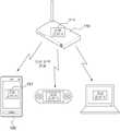
도 1은 본 발명의 일 실시 예에 따른 무선 전력 전송 장치로부터 타겟 장치로 전력을 무선 전송하는 동작을 나타낸다.Figure 1 illustrates the operation of wirelessly transmitting power from a wireless power transmission device to a target device in accordance with an embodiment of the present invention.
도 1을 참조하면, 본 발명의 일 실시 예에 따른 무선 전력 전송 장치(110)는 타겟 장치(120)에게 전력을 무선 전송한다. 무선 전력 전송 장치(110)는 전원 공진기(source resonator)(111)를 포함하며, 타겟 장치(120)는 대상 공진기(target resonator)(121)를 포함한다. 무선 전력 전송 장치(110)는 휴대용 단말기에 일 모듈의 형태로 삽입되도록 구현될 수 있다.Referring to FIG. 1, a wireless
도 2는 본 발명의 일 실시 예에 따른 무선 전력 전송 장치를 나타낸다.2 shows a wireless power transmission apparatus according to an embodiment of the present invention.
도 2를 참조하면, 무선 전력 전송 장치(210)는 소스부(211) 및 근접필드 포커싱부(213)를 포함한다.Referring to FIG. 2, the wireless
소스부(211)는 타겟 장치(120)로 무선 전력을 전송하는 전원 공진기를 포함한다. 또한, 소스부(211)는 타겟 장치(120)의 위치 또는 방향을 측정하기 위한 수 단을 포함할 수 있다. 이때, 타겟 장치(120)의 위치 또는 방향을 측정하기 위한 수단은, 타겟 장치(120)와의 통신 채널을 통하여 위치 정보를 수신하는 통신 모듈일 수 있다. 또한, 타겟 장치(120)의 위치 또는 방향을 측정하기 위한 수단은, 타겟 장치(120)별로 기 설정된 방향을 검출하는 수단일 수 있다.The
근접필드 포커싱부(213)는 전원 공진기의 전방향으로 방사되는 마그네틱 필드의 근접필드(near field)를 타겟 장치(120)측으로 포커싱(focusing)한다. 근접필드 포커싱부(213)는 도 3에 도시한 바와 같이, 음의 굴절 특성(negative refractive index)을 갖는 메타-수퍼스트레이트(Meta-Superstrate)로 구성될 수 있다. 이때, 음의 굴절 특성을 갖는 메타-수퍼스트레이트(Meta-Superstrate)는 도 3의 실선 화살표로 표시된 바와 같이, 점선화살표로 표시된 일반적인 매질과는 반대 방향으로 입사 파(wave)를 투과시키는 특성을 갖는다. 따라서, 음의 굴절 특성을 갖는 메타-수퍼스트레이트에 의하여 마그네틱 필드의 근접필드는 타겟장치(120) 측으로 포커싱 될 수 있다.The near
한편, 근접필드 포커싱부(213)는 도 4에 도시한 바와 같이, 빔 포밍(beam forming) 특성을 갖는 MNZ(Mu Near Zero) 또는 ENG(Epsilon Near Zero) 수퍼스트레이트로 구성될 수 있다. 이때, MNZ(Mu Near Zero) 또는 ENG(Epsilon Near Zero) 수퍼스트레이트는 실선 화살표로 표시된 바와 같이, 점선화살표로 표시된 일반적인 매질과는 달리, 웨이브(wave)의 입사각에 상관 없이 입사된 웨이브를 투과면에 직각으로 투과시키는 특성을 갖는다. 예를 들어, 도 5에 도시된 바와 같이 근접필드 포커싱부(213)는 타겟장치(120) 측으로 구부러진 형상으로 구비될 수 있으며, 이 때, 근접필드는 근접필드 포커싱부(213)의 투과면에 직각으로 형성될 수 있다.Meanwhile, as shown in FIG. 4, the near
근접필드 포커싱부(213)는 무선 전력 전송 시 원하지 않는 방향으로 방사되는 마그네틱 필드를 타겟 장치로 포커싱한다. 따라서, 본 발명의 실시 예에 따르면, 방사되는 에너지로 인한 주변 기기에 미치는 간섭(interference)를 방지할 수 있다. 또한, 전원 공진기의 전방향으로 방사되는 마그네틱 필드의 근접필드(near field)를 타겟 장치(120)측으로 포커싱(focusing)함으로써, 에너지 전송 효율을 증가시킬 수 있다.The near
도 6은 본 발명의 다른 실시 예에 따른 무선 전력 전송 장치를 나타낸다.6 shows a wireless power transmission apparatus according to another embodiment of the present invention.
도 6을 참조하면, 무선 전력 전송 장치(610)는 소스부(211), 근접필드 포커싱부(213) 및 근접필드 제어부(615)를 포함한다. 도 6에 도시된 소스부(211) 및 근접필드 포커싱부(213)는 도 2 내지 도 5에 도시된 소스부(211) 및 근접필드 포커싱부(213)와 동일한 구성을 나타낸다.Referring to FIG. 6, the wireless
근접필드 제어부(615)는 높은 임피던스 표면(HIS, High Impedance Suffice) 특성을 갖도록 설계될수 있다. 이에 따라, 근접필드 제어부(615)는 Ground Effect를 최소화 함으로써, 전원 공진기의 공진 주파수나 Q-factor의 변화를 최소화 시킬 수 있다.The near
이때, High Impedance Suffice 특성은, 소스부(211)의 공진 주파수를 고려하여 설계될 수 있다. 즉, 근접필드 제어부(615)는 소스부(211)의 마그네틱 필드가 인-페이즈(in-phase) 특성을 갖도록 설계될 수 있다. 근접필드 제어부(615)가 High Impedance Suffice 특성을 갖는 경우, 소스부(211)에서 발생되는 마그네틱 필드는 근접필드 제어부(615)에 대하여 in-phase 특성을 갖게 된다. 따라서, 본 발명의 일 실시 예에 따르면, 마그네틱 필드에 민감한 주변 장치에 미치는 영향을 최소화 할 수 있다.At this time, the high impedance suffice characteristic can be designed in consideration of the resonance frequency of the
이때, 근접필드 제어부(615)는 사이드 포커싱부, 후면 포커싱부 및 방향조정부를 포함하여 구성될 수 있다. 사이드 포커싱부는, 도 6에 도시된 바와 같이, 소스부(211)의 측면 마그네틱 필드가 타겟 장치로 포커싱 되도록, 소스부(211)의 측면 마그네틱 필드의 방향을 제어할 수 있다. 후면 포커싱부는, 도 6에 도시된 바와 같이, 소스부(211)의 후면 마그네틱 필드가 타겟 장치로 포커싱 되도록, 소스부(211)의 후면 마그네틱 필드의 방향을 제어할 수 있다.At this time, the near
이상과 같이 본 발명은 비록 한정된 실시예와 도면에 의해 설명되었으나, 본 발명은 상기의 실시예에 한정되는 것은 아니며, 본 발명이 속하는 분야에서 통상의 지식을 가진 자라면 이러한 기재로부터 다양한 수정 및 변형이 가능하다.While the invention has been shown and described with reference to certain preferred embodiments thereof, it will be understood by those of ordinary skill in the art that various changes in form and details may be made therein without departing from the spirit and scope of the invention as defined by the appended claims. This is possible.
그러므로, 본 발명의 범위는 설명된 실시예에 국한되어 정해져서는 아니 되며, 후술하는 특허청구범위뿐 아니라 이 특허청구범위와 균등한 것들에 의해 정해져야 한다.Therefore, the scope of the present invention should not be limited to the described embodiments, but should be determined by the equivalents of the claims, as well as the claims.
도 1은 본 발명의 일 실시 예에 따른 무선 전력 전송 장치로부터 타겟 장치로 전력을 무선 전송하는 동작을 나타낸다.Figure 1 illustrates the operation of wirelessly transmitting power from a wireless power transmission device to a target device in accordance with an embodiment of the present invention.
도 2는 본 발명의 일 실시 예에 따른 무선 전력 전송 장치를 나타낸다.2 shows a wireless power transmission apparatus according to an embodiment of the present invention.
도 3 내지 도 5는 도 2의 근접필드 포커싱부의 구성 예들을 나타낸다.FIGS. 3 to 5 show exemplary configurations of the near field focusing unit of FIG.
도 6은 본 발명의 다른 실시 예에 따른 무선 전력 전송 장치를 나타낸다.6 shows a wireless power transmission apparatus according to another embodiment of the present invention.
Claims (6)
Translated fromKoreanPriority Applications (6)
| Application Number | Priority Date | Filing Date | Title |
|---|---|---|---|
| KR1020090133596AKR101706693B1 (en) | 2009-12-30 | 2009-12-30 | Wireless power transmission apparatus using near field focusing |
| US12/978,553US9013068B2 (en) | 2009-12-30 | 2010-12-25 | Wireless power transmission apparatus using near field focusing |
| EP10841298.2AEP2520004B1 (en) | 2009-12-30 | 2010-12-30 | Wireless power transmission apparatus using near field focusing |
| CN201080060375.7ACN102696166B (en) | 2009-12-30 | 2010-12-30 | Utilize the wireless power transmission apparatus of near field focus |
| PCT/KR2010/009541WO2011081466A2 (en) | 2009-12-30 | 2010-12-30 | Wireless power transmission apparatus using near field focusing |
| JP2012547029AJP5689139B2 (en) | 2009-12-30 | 2010-12-30 | Wireless power transmitter using proximity field focusing |
Applications Claiming Priority (1)
| Application Number | Priority Date | Filing Date | Title |
|---|---|---|---|
| KR1020090133596AKR101706693B1 (en) | 2009-12-30 | 2009-12-30 | Wireless power transmission apparatus using near field focusing |
Publications (2)
| Publication Number | Publication Date |
|---|---|
| KR20110077130A KR20110077130A (en) | 2011-07-07 |
| KR101706693B1true KR101706693B1 (en) | 2017-02-14 |
Family
ID=44186597
Family Applications (1)
| Application Number | Title | Priority Date | Filing Date |
|---|---|---|---|
| KR1020090133596AExpired - Fee RelatedKR101706693B1 (en) | 2009-12-30 | 2009-12-30 | Wireless power transmission apparatus using near field focusing |
Country Status (6)
| Country | Link |
|---|---|
| US (1) | US9013068B2 (en) |
| EP (1) | EP2520004B1 (en) |
| JP (1) | JP5689139B2 (en) |
| KR (1) | KR101706693B1 (en) |
| CN (1) | CN102696166B (en) |
| WO (1) | WO2011081466A2 (en) |
Families Citing this family (23)
| Publication number | Priority date | Publication date | Assignee | Title |
|---|---|---|---|---|
| WO2011005012A2 (en)* | 2009-07-06 | 2011-01-13 | 삼성전자주식회사 | Wireless power transmission system and resonator for the system |
| KR101718715B1 (en)* | 2010-04-28 | 2017-03-22 | 삼성전자주식회사 | Method and Apparatus of Controlling of Resonance Bandwidth in Wireless Power Transform System |
| US8441153B2 (en)* | 2010-06-22 | 2013-05-14 | General Electric Company | Contactless power transfer system |
| EP2551988A3 (en)* | 2011-07-28 | 2013-03-27 | General Electric Company | Dielectric materials for power transfer system |
| EP2551250B1 (en)* | 2011-07-28 | 2016-12-07 | General Electric Company | Dielectric materials for power tranfer system |
| KR101209979B1 (en)* | 2011-10-24 | 2012-12-07 | 엘지이노텍 주식회사 | Apparatus for shielding and apparatus for transmissing wireless power |
| US9079043B2 (en)* | 2011-11-21 | 2015-07-14 | Thoratec Corporation | Transcutaneous power transmission utilizing non-planar resonators |
| US9431856B2 (en) | 2012-01-09 | 2016-08-30 | Pabellon, Inc. | Power transmission |
| US8933589B2 (en) | 2012-02-07 | 2015-01-13 | The Gillette Company | Wireless power transfer using separately tunable resonators |
| CN103296781A (en)* | 2012-03-01 | 2013-09-11 | 深圳光启创新技术有限公司 | Wireless energy transmitting system |
| US9231309B2 (en)* | 2012-07-27 | 2016-01-05 | Toyota Motor Engineering & Manufacturing North America, Inc. | Metamaterial magnetic field guide |
| JP2014195364A (en)* | 2013-03-28 | 2014-10-09 | Ryutech Co Ltd | Wireless power transmission system |
| KR20140129926A (en)* | 2013-04-30 | 2014-11-07 | 인텔렉추얼디스커버리 주식회사 | Meta material structure |
| US10114120B2 (en)* | 2014-04-16 | 2018-10-30 | The Regents Of The University Of Michigan | Unidirectional near-field focusing using near-field plates |
| KR102208964B1 (en)* | 2014-05-30 | 2021-01-28 | 삼성전자주식회사 | Near field lens and imaging apparatus including the same |
| WO2016134107A1 (en)* | 2015-02-19 | 2016-08-25 | Arizona Board Of Regents On Behalf Of Arizona State University | Virtual magnetic transmission lines for communication and power transfer in conducting media |
| JP2019140658A (en) | 2017-03-21 | 2019-08-22 | 京セラ株式会社 | Composite antenna, radio communication module, and radio communication equipment |
| JP6930292B2 (en)* | 2017-08-29 | 2021-09-01 | 富士通株式会社 | Power relay device, transmitter, power receiver, and power transmission / reception system |
| US10622845B2 (en)* | 2017-12-05 | 2020-04-14 | Searete Llc | Non-Gaussian beamforming for wireless power transfer optimization |
| CN109038867A (en)* | 2018-08-10 | 2018-12-18 | 华中科技大学 | The wireless power transmission systems performance boost device combined based on negative magnetic and zero magnetic Meta Materials |
| JP2019187237A (en)* | 2019-05-24 | 2019-10-24 | 株式会社リューテック | Wireless power transmission system |
| DE102020210894A1 (en) | 2020-08-28 | 2022-03-03 | Fraunhofer-Gesellschaft zur Förderung der angewandten Forschung eingetragener Verein | Transmission device and energy transmission system for the contactless transmission of electrical energy |
| CN113300493B (en)* | 2021-05-31 | 2022-11-01 | 桂林电子科技大学 | Magnetically coupled resonant wireless power transfer system based on electromagnetic metamaterials |
Citations (4)
| Publication number | Priority date | Publication date | Assignee | Title |
|---|---|---|---|---|
| JP2004064780A (en)* | 2003-08-27 | 2004-02-26 | Hiroji Kawakami | antenna |
| JP2005110273A (en)* | 2003-09-30 | 2005-04-21 | Denso Corp | Multiple-frequency common antenna |
| WO2009065099A2 (en)* | 2007-11-16 | 2009-05-22 | Nigel Power, Llc | Wireless power bridge |
| JP2011045045A (en) | 2009-07-23 | 2011-03-03 | Nippon Soken Inc | Power transmitting/receiving antenna and power transmitter |
Family Cites Families (32)
| Publication number | Priority date | Publication date | Assignee | Title |
|---|---|---|---|---|
| US6512494B1 (en)* | 2000-10-04 | 2003-01-28 | E-Tenna Corporation | Multi-resonant, high-impedance electromagnetic surfaces |
| US6690327B2 (en)* | 2001-09-19 | 2004-02-10 | Etenna Corporation | Mechanically reconfigurable artificial magnetic conductor |
| USRE43699E1 (en)* | 2002-02-05 | 2012-10-02 | Theodore R. Anderson | Reconfigurable scanner and RFID system using the scanner |
| US6922173B2 (en)* | 2002-02-05 | 2005-07-26 | Theodore R. Anderson | Reconfigurable scanner and RFID system using the scanner |
| US6859114B2 (en)* | 2002-05-31 | 2005-02-22 | George V. Eleftheriades | Metamaterials for controlling and guiding electromagnetic radiation and applications therefor |
| JP4089778B2 (en) | 2002-11-07 | 2008-05-28 | 株式会社アイデンビデオトロニクス | Energy supply equipment |
| US7151506B2 (en)* | 2003-04-11 | 2006-12-19 | Qortek, Inc. | Electromagnetic energy coupling mechanism with matrix architecture control |
| US7456803B1 (en) | 2003-05-12 | 2008-11-25 | Hrl Laboratories, Llc | Large aperture rectenna based on planar lens structures |
| US7154451B1 (en)* | 2004-09-17 | 2006-12-26 | Hrl Laboratories, Llc | Large aperture rectenna based on planar lens structures |
| US6985118B2 (en)* | 2003-07-07 | 2006-01-10 | Harris Corporation | Multi-band horn antenna using frequency selective surfaces |
| US7190315B2 (en)* | 2003-12-18 | 2007-03-13 | Intel Corporation | Frequency selective surface to suppress surface currents |
| US7190325B2 (en)* | 2004-02-18 | 2007-03-13 | Delphi Technologies, Inc. | Dynamic frequency selective surfaces |
| US7218285B2 (en) | 2004-08-05 | 2007-05-15 | The Boeing Company | Metamaterial scanning lens antenna systems and methods |
| EP1782434A1 (en) | 2004-08-09 | 2007-05-09 | George V. Eleftheriades | Negative-refraction metamaterials using continuous metallic grids over ground for controlling and guiding electromagnetic radiation |
| US7593696B2 (en) | 2005-02-10 | 2009-09-22 | Alcatel-Lucent Usa Inc. | Tunable radio frequency filter |
| US20070159396A1 (en)* | 2006-01-06 | 2007-07-12 | Sievenpiper Daniel F | Antenna structures having adjustable radiation characteristics |
| JP2009535942A (en)* | 2006-04-27 | 2009-10-01 | レイスパン コーポレーション | Antennas, devices, and systems based on metamaterial structures |
| AU2007281584A1 (en)* | 2006-07-29 | 2008-02-07 | Powercast Corporation | RF power transmission network and method |
| WO2008024993A2 (en)* | 2006-08-25 | 2008-02-28 | Rayspan Corporation | Antennas based on metamaterial structures |
| US7928900B2 (en) | 2006-12-15 | 2011-04-19 | Alliant Techsystems Inc. | Resolution antenna array using metamaterials |
| US8482157B2 (en)* | 2007-03-02 | 2013-07-09 | Qualcomm Incorporated | Increasing the Q factor of a resonator |
| US8003965B2 (en) | 2007-05-18 | 2011-08-23 | The Regents Of The University Of Michigan | Apparatus for sub-wavelength near-field focusing of electromagnetic waves |
| EP2186211A4 (en)* | 2007-08-13 | 2016-08-10 | Qualcomm Inc | Long range low frequency resonator and materials |
| DE102007060811A1 (en) | 2007-09-01 | 2009-03-05 | Maquet Gmbh & Co. Kg | Device and method for wireless energy and / or data transmission between a source device and at least one target device |
| US7570432B1 (en) | 2008-02-07 | 2009-08-04 | Toyota Motor Engineering & Manufacturing North America, Inc. | Metamaterial gradient index lens |
| US8180213B2 (en) | 2008-04-24 | 2012-05-15 | Raytheon Company | Methods and systems for optical focusing using negative index metamaterial |
| JP5106237B2 (en) | 2008-05-02 | 2012-12-26 | オリンパス株式会社 | Wireless power supply system |
| US8400017B2 (en)* | 2008-09-27 | 2013-03-19 | Witricity Corporation | Wireless energy transfer for computer peripheral applications |
| US8295788B2 (en)* | 2009-06-09 | 2012-10-23 | Broadcom Corporation | Method and system for an N-phase transmitter utilizing a leaky wave antenna |
| US20110084782A1 (en)* | 2009-10-09 | 2011-04-14 | Hiroshi Kanno | Electromagnetic filter and electronic device having same |
| KR101688893B1 (en)* | 2009-12-14 | 2016-12-23 | 삼성전자주식회사 | Wireless power transmission apparatus |
| US8884834B1 (en)* | 2012-09-21 | 2014-11-11 | First Rf Corporation | Antenna system with an antenna and a high-impedance backing |
- 2009
- 2009-12-30KRKR1020090133596Apatent/KR101706693B1/ennot_activeExpired - Fee Related
- 2010
- 2010-12-25USUS12/978,553patent/US9013068B2/enactiveActive
- 2010-12-30CNCN201080060375.7Apatent/CN102696166B/ennot_activeExpired - Fee Related
- 2010-12-30WOPCT/KR2010/009541patent/WO2011081466A2/ennot_activeCeased
- 2010-12-30EPEP10841298.2Apatent/EP2520004B1/ennot_activeNot-in-force
- 2010-12-30JPJP2012547029Apatent/JP5689139B2/ennot_activeExpired - Fee Related
Patent Citations (4)
| Publication number | Priority date | Publication date | Assignee | Title |
|---|---|---|---|---|
| JP2004064780A (en)* | 2003-08-27 | 2004-02-26 | Hiroji Kawakami | antenna |
| JP2005110273A (en)* | 2003-09-30 | 2005-04-21 | Denso Corp | Multiple-frequency common antenna |
| WO2009065099A2 (en)* | 2007-11-16 | 2009-05-22 | Nigel Power, Llc | Wireless power bridge |
| JP2011045045A (en) | 2009-07-23 | 2011-03-03 | Nippon Soken Inc | Power transmitting/receiving antenna and power transmitter |
Also Published As
| Publication number | Publication date |
|---|---|
| US20110156492A1 (en) | 2011-06-30 |
| JP2013516830A (en) | 2013-05-13 |
| EP2520004B1 (en) | 2018-06-13 |
| WO2011081466A2 (en) | 2011-07-07 |
| US9013068B2 (en) | 2015-04-21 |
| EP2520004A4 (en) | 2017-08-30 |
| KR20110077130A (en) | 2011-07-07 |
| EP2520004A2 (en) | 2012-11-07 |
| CN102696166A (en) | 2012-09-26 |
| WO2011081466A3 (en) | 2011-11-24 |
| CN102696166B (en) | 2015-11-25 |
| JP5689139B2 (en) | 2015-03-25 |
Similar Documents
| Publication | Publication Date | Title |
|---|---|---|
| KR101706693B1 (en) | Wireless power transmission apparatus using near field focusing | |
| KR101688893B1 (en) | Wireless power transmission apparatus | |
| US8023890B2 (en) | Communication system, communication apparatus, and electric-field-coupling antenna | |
| US8238824B2 (en) | Communication system and communication apparatus | |
| KR101167401B1 (en) | Apparatus for transmitting and receiving wireless energy using meta material structure having zero refractive index | |
| KR101373208B1 (en) | Electric device, wireless power transmission device and power transmission method thereof | |
| KR101694950B1 (en) | Apparatus and method for wireless energy suppliment | |
| US9246359B2 (en) | Apparatus for harvesting leakage energy | |
| ATE403244T1 (en) | WAVEGUIDE SLOT ANTENNA | |
| JP2012090228A (en) | Electronic device and antenna unit | |
| US10581277B2 (en) | Apparatus for reducing electromagnetic wave in wireless power transmitter using reducing coil | |
| Kim et al. | Experimental demonstration of optical wireless power transfer with a DC-to-DC transfer efficiency of 12.1% | |
| US20200161904A1 (en) | Systems and methods for wireless power transmission | |
| EP2518863A1 (en) | Methods and apparatuses for wireless power transfer | |
| KR101983138B1 (en) | Apparatus and method wireless power transmission, and wireless power transmission system using the same | |
| KR101584909B1 (en) | Yagi-uda antenna and wireless power transfer apparatus comprising the same | |
| KR20130095124A (en) | Magnetic focusing table for wireless power transmission | |
| CN106340978A (en) | Long-distance wireless power transmission system | |
| US8954002B2 (en) | Wireless communication apparatus including high-frequency coupler | |
| Katbay et al. | Retrodirective wireless power transfer for short and long range applications | |
| Shuai et al. | 1‐Bit reconfigurable transmitarray with low insertion loss for wireless power transmission | |
| TWI873284B (en) | Near electric field communication | |
| TWI812943B (en) | Passive sensing device | |
| KR20200099903A (en) | Wireless power transmission device and method the same | |
| Yazaki et al. | Demonstration of optical wireless USB 2.0 system with wireless power transfer |
Legal Events
| Date | Code | Title | Description |
|---|---|---|---|
| PA0109 | Patent application | St.27 status event code:A-0-1-A10-A12-nap-PA0109 | |
| PG1501 | Laying open of application | St.27 status event code:A-1-1-Q10-Q12-nap-PG1501 | |
| R18-X000 | Changes to party contact information recorded | St.27 status event code:A-3-3-R10-R18-oth-X000 | |
| A201 | Request for examination | ||
| PA0201 | Request for examination | St.27 status event code:A-1-2-D10-D11-exm-PA0201 | |
| P22-X000 | Classification modified | St.27 status event code:A-2-2-P10-P22-nap-X000 | |
| E902 | Notification of reason for refusal | ||
| PE0902 | Notice of grounds for rejection | St.27 status event code:A-1-2-D10-D21-exm-PE0902 | |
| E13-X000 | Pre-grant limitation requested | St.27 status event code:A-2-3-E10-E13-lim-X000 | |
| P11-X000 | Amendment of application requested | St.27 status event code:A-2-2-P10-P11-nap-X000 | |
| P13-X000 | Application amended | St.27 status event code:A-2-2-P10-P13-nap-X000 | |
| E701 | Decision to grant or registration of patent right | ||
| PE0701 | Decision of registration | St.27 status event code:A-1-2-D10-D22-exm-PE0701 | |
| GRNT | Written decision to grant | ||
| PR0701 | Registration of establishment | St.27 status event code:A-2-4-F10-F11-exm-PR0701 | |
| PR1002 | Payment of registration fee | St.27 status event code:A-2-2-U10-U11-oth-PR1002 Fee payment year number:1 | |
| PG1601 | Publication of registration | St.27 status event code:A-4-4-Q10-Q13-nap-PG1601 | |
| P22-X000 | Classification modified | St.27 status event code:A-4-4-P10-P22-nap-X000 | |
| FPAY | Annual fee payment | Payment date:20200130 Year of fee payment:4 | |
| PR1001 | Payment of annual fee | St.27 status event code:A-4-4-U10-U11-oth-PR1001 Fee payment year number:4 | |
| PC1903 | Unpaid annual fee | St.27 status event code:A-4-4-U10-U13-oth-PC1903 Not in force date:20210209 Payment event data comment text:Termination Category : DEFAULT_OF_REGISTRATION_FEE | |
| P22-X000 | Classification modified | St.27 status event code:A-4-4-P10-P22-nap-X000 | |
| PC1903 | Unpaid annual fee | St.27 status event code:N-4-6-H10-H13-oth-PC1903 Ip right cessation event data comment text:Termination Category : DEFAULT_OF_REGISTRATION_FEE Not in force date:20210209 | |
| P22-X000 | Classification modified | St.27 status event code:A-4-4-P10-P22-nap-X000 |