KR101706094B1 - Robot joint driving apparatus and robot having the same, cable linking method of robot joint driving apparatus - Google Patents
Robot joint driving apparatus and robot having the same, cable linking method of robot joint driving apparatusDownload PDFInfo
- Publication number
- KR101706094B1 KR101706094B1KR1020100003518AKR20100003518AKR101706094B1KR 101706094 B1KR101706094 B1KR 101706094B1KR 1020100003518 AKR1020100003518 AKR 1020100003518AKR 20100003518 AKR20100003518 AKR 20100003518AKR 101706094 B1KR101706094 B1KR 101706094B1
- Authority
- KR
- South Korea
- Prior art keywords
- cable
- output pulley
- line
- moving member
- robot
- Prior art date
- Legal status (The legal status is an assumption and is not a legal conclusion. Google has not performed a legal analysis and makes no representation as to the accuracy of the status listed.)
- Active
Links
Images


Classifications
- B—PERFORMING OPERATIONS; TRANSPORTING
- B25—HAND TOOLS; PORTABLE POWER-DRIVEN TOOLS; MANIPULATORS
- B25J—MANIPULATORS; CHAMBERS PROVIDED WITH MANIPULATION DEVICES
- B25J9/00—Programme-controlled manipulators
- B25J9/10—Programme-controlled manipulators characterised by positioning means for manipulator elements
- B25J9/104—Programme-controlled manipulators characterised by positioning means for manipulator elements with cables, chains or ribbons
- B—PERFORMING OPERATIONS; TRANSPORTING
- B25—HAND TOOLS; PORTABLE POWER-DRIVEN TOOLS; MANIPULATORS
- B25J—MANIPULATORS; CHAMBERS PROVIDED WITH MANIPULATION DEVICES
- B25J17/00—Joints
- B25J17/02—Wrist joints
- B25J17/0241—One-dimensional joints
- B—PERFORMING OPERATIONS; TRANSPORTING
- B25—HAND TOOLS; PORTABLE POWER-DRIVEN TOOLS; MANIPULATORS
- B25J—MANIPULATORS; CHAMBERS PROVIDED WITH MANIPULATION DEVICES
- B25J19/00—Accessories fitted to manipulators, e.g. for monitoring, for viewing; Safety devices combined with or specially adapted for use in connection with manipulators
- B—PERFORMING OPERATIONS; TRANSPORTING
- B25—HAND TOOLS; PORTABLE POWER-DRIVEN TOOLS; MANIPULATORS
- B25J—MANIPULATORS; CHAMBERS PROVIDED WITH MANIPULATION DEVICES
- B25J9/00—Programme-controlled manipulators
- B25J9/10—Programme-controlled manipulators characterised by positioning means for manipulator elements
- B25J9/12—Programme-controlled manipulators characterised by positioning means for manipulator elements electric
- B25J9/126—Rotary actuators
- Y—GENERAL TAGGING OF NEW TECHNOLOGICAL DEVELOPMENTS; GENERAL TAGGING OF CROSS-SECTIONAL TECHNOLOGIES SPANNING OVER SEVERAL SECTIONS OF THE IPC; TECHNICAL SUBJECTS COVERED BY FORMER USPC CROSS-REFERENCE ART COLLECTIONS [XRACs] AND DIGESTS
- Y10—TECHNICAL SUBJECTS COVERED BY FORMER USPC
- Y10S—TECHNICAL SUBJECTS COVERED BY FORMER USPC CROSS-REFERENCE ART COLLECTIONS [XRACs] AND DIGESTS
- Y10S901/00—Robots
- Y10S901/27—Arm part
- Y10S901/28—Joint
- Y—GENERAL TAGGING OF NEW TECHNOLOGICAL DEVELOPMENTS; GENERAL TAGGING OF CROSS-SECTIONAL TECHNOLOGIES SPANNING OVER SEVERAL SECTIONS OF THE IPC; TECHNICAL SUBJECTS COVERED BY FORMER USPC CROSS-REFERENCE ART COLLECTIONS [XRACs] AND DIGESTS
- Y10—TECHNICAL SUBJECTS COVERED BY FORMER USPC
- Y10T—TECHNICAL SUBJECTS COVERED BY FORMER US CLASSIFICATION
- Y10T74/00—Machine element or mechanism
- Y10T74/20—Control lever and linkage systems
- Y10T74/20207—Multiple controlling elements for single controlled element
- Y10T74/20305—Robotic arm
- Y10T74/20323—Robotic arm including flaccid drive element
Landscapes
- Engineering & Computer Science (AREA)
- Robotics (AREA)
- Mechanical Engineering (AREA)
- Manipulator (AREA)
Abstract
Translated fromKoreanDescription
Translated fromKorean본 발명은 로봇용 관절 구동장치 및 이를 포함하는 로봇, 로봇용 관절 구동장치의 케이블 연결방법에 관한 것으로서, 특히 로봇 관절부의 회전 강성이 강화된 로봇용 관절 구동장치 및 이를 포함하는 로봇, 로봇용 관절 구동장치의 케이블 연결방법에 관한 것이다.BACKGROUND OF THE INVENTION 1. Field of the Invention The present invention relates to a joint driving apparatus for a robot, a robot including the same, and a cable connecting method for the joint driving apparatus for a robot. More particularly, the present invention relates to a joint driving apparatus for a robot, And a cable connecting method of the driving apparatus.
가정용, 군사용, 산업용 등의 목적으로 2족 보행, 4족 보행 등이 가능한 다양한 형태의 로봇이 개발되고 있다.Various types of robots capable of bipedal walking and quadruped walking are being developed for the purposes of household, military, and industrial use.
특히, 인간형 로봇은 인간의 신체구조와 유사하게 만든 로봇으로서 인간의 동작과 유사한 동작을 수행하도록 하는 것이 그 제작 목적이 된다.Particularly, a humanoid robot is a robot made similar to a human body structure, and its purpose is to perform an operation similar to a human motion.
이러한 로봇은 인간의 관절과 유사한 관절의 운동을 통해 달리기, 걷기 등의 보행동작 뿐만 아니라 다양한 동작을 구현하게 된다.These robots implement not only gait movements such as running and walking but also various movements through movement of joints similar to human joints.
관절을 구동하는 방식으로는 모터 및 모터에 연결된 감속기를 이용하여 관절을 구동하는 방식과 케이블을 이용하여 관절을 구동하는 방식이 있다.There are two ways of driving joints: a method of driving joints using a motor and a speed reducer connected to a motor, and a method of driving joints using cables.
본 발명의 일 측면은 구조가 개선된 로봇용 관절 구동장치 및 이를 포함하는 로봇, 로봇용 관절 구동장치의 케이블 연결방법을 제공하는 것이다.One aspect of the present invention provides a joint driving apparatus for a robot, a robot including the same, and a cable connecting method for a joint driving apparatus for a robot.
또한, 로봇 관절부의 회전 강성(torsional stiffness)이 강화된 로봇용 관절 구동장치 및 이를 포함하는 로봇, 로봇용 관절 구동장치의 케이블 연결방법을 제공하는 것이다.The present invention also provides a joint driving apparatus for a robot having enhanced torsional stiffness of the robot joint, and a method of connecting a cable of a robot and a joint driving apparatus for the same.
또한, 출력 풀리에서 슬립 현상이 일어나지 않도록 하는 로봇용 관절 구동장치 및 이를 포함하는 로봇, 로봇용 관절 구동장치의 케이블 연결방법을 제공하는 것이다.It is another object of the present invention to provide a joint drive device for a robot that prevents a slip phenomenon from occurring in an output pulley, a robot including the same, and a cable connection method for a joint drive device for a robot.
또한, 전체적으로 크기가 작아진 로봇용 관절 구동장치 및 이를 포함하는 로봇, 로봇용 관절 구동장치의 케이블 연결방법을 제공하는 것이다.It is another object of the present invention to provide a joint drive device for a robot having a small overall size, a robot including the same, and a cable connection method for a joint drive device for a robot.
본 발명의 사상에 따르면, 로봇용 관절 구동장치는 정방향, 역방향으로 회전 가능하도록 마련되는 구동모터와, 상기 구동모터의 구동력을 전달받아 직선 운동하는 이동부재와, 상기 이동부재의 양방향에서 연결되는 케이블(cable)과, 상기 케이블의 일측부와 접촉하여 회전하는 아이들 풀리(idle pulley)와, 상기 케이블의 타측부와 접촉하여 회전하며 관절부를 직접 구동하는 출력 풀리를 포함하고, 상기 케이블은 상기 아이들 풀리, 이동부재 및 출력 풀리 사이에서 적어도 1회 병렬로 연결되는 것을 특징으로 한다.According to an aspect of the present invention, a joint drive apparatus for a robot includes a drive motor provided to be rotatable in a forward direction and a reverse direction, a moving member that linearly moves under the driving force of the driving motor, an idle pulley rotating in contact with one side of the cable and an output pulley rotating in contact with the other side of the cable and directly driving the joint, , The moving member and the output pulley at least once in parallel.
상기 케이블은 1줄의 케이블로 폐루프(closed loop)를 형성하고, 상기 1줄 케이블의 양단부는 상기 케이블을 압착하도록 형성되는 연결 루프 슬리브(loop sleeve)에 의해 연결될 수 있다.The cable forms a closed loop with a single row of cables, and both ends of the single row cable can be connected by a loop sleeve formed to compress the cable.
상기 케이블은 일측에서 상기 출력 풀리와 아이들 풀리 사이에 형성되는 제1라인과, 상기 제1라인의 측면에 병렬로 마련되는 제2라인과, 상기 제2라인의 측면에 병렬로 마련되는 제3라인과, 상기 제3라인의 측면에 병렬로 마련되는 제4라인을 포함할 수 있다.The cable includes a first line formed between the output pulley and the idle pulley at one side, a second line provided in parallel at the side of the first line, and a second line formed in parallel at the side of the second line, And a fourth line provided in parallel on the side of the third line.
상기 출력 풀리는 상기 케이블과의 슬립(slip) 현상을 방지하기 위한 케이블 고정부를 포함할 수 있다.The output pulley may include a cable fixing portion to prevent a slip phenomenon with the cable.
상기 케이블 고정부는 상기 케이블이 상기 출력 풀리의 축 방향과 평행하게 배치되도록 가이드 하는 케이블 가이드 브라켓(bracket)을 포함할 수 있다.The cable fixing part may include a cable guide bracket for guiding the cable to be disposed parallel to the axial direction of the output pulley.
상기 출력 풀리와 접촉하는 상기 케이블의 부위에는 상기 케이블을 압착하도록 형성되는 고정 루프 슬리브(loop sleeve)가 끼워지고, 상기 케이블 고정부는 상기 고정 루프 슬리브가 상기 출력 풀리에 고정되도록 하는 스페이서(spacer)를 포함할 수 있다.A portion of the cable in contact with the output pulley is fitted with a loop sleeve formed to compress the cable, and the cable fixing portion includes a spacer for fixing the fixed loop sleeve to the output pulley .
상기 이동부재가 나사 결합되는 볼 스크류부를 더 포함할 수 있다.And a ball screw unit to which the moving member is screwed.
상기 볼 스크류부가 결합되는 볼 스크류부 프레임을 더 포함하고, 상기 볼 스크류부 프레임은 상기 이동부재의 회전이 방지되도록 가이드 하는 가이드 슬롯(guide slot)을 포함할 수 있다.The ball screw subframe may further include a guide slot for guiding the rotation of the moving member to be prevented.
상기 이동부재는 상기 가이드 슬롯에 끼워져 이동하는 적어도 하나의 가이드 베어링을 포함할 수 있다.The moving member may include at least one guide bearing that moves in the guide slot.
상기 이동부재는 몸체를 형성하며 상기 케이블이 결합되는 장착 블럭(block)을 포함하고, 상기 장착 블럭은 상기 케이블이 결합될 수 있도록 마련되는 케이블 결합부를 포함할 수 있다.The moving member may include a block to form a body and to which the cable is coupled, and the mounting block may include a cable coupling portion to which the cable can be coupled.
상기 케이블 결합부는 상기 케이블이 병렬로 걸리도록 상기 장착 블럭에 결합되는 제1가이드 핀(guide pin)과, 상기 케이블 사이의 간격이 줄어들도록 상기 장착 블럭에 결합되는 제2가이드 핀을 포함할 수 있다.The cable coupling portion may include a first guide pin coupled to the mounting block so that the cable is juxtaposed in parallel, and a second guide pin coupled to the mounting block such that the gap between the cables is reduced .
또한, 로봇은 로봇의 관절부를 구동하는 관절 구동장치를 포함하는 로봇에 있어서, 상기 관절 구동장치는 정방향, 역방향으로 회전 가능하도록 마련되는 구동모터와, 상기 구동모터의 구동력을 전달받아 직선 운동하는 이동부재와, 상기 이동부재의 양방향에서 연결되는 케이블과, 상기 케이블의 일측부와 접촉하여 회전하는 아이들(idle) 풀리와, 상기 케이블의 타측부와 접촉하여 회전하며 상기 관절부를 직접 구동하는 출력 풀리를 포함하고, 상기 케이블은 상기 관절부의 회전 강성(torsional stiffness)이 커지도록 적어도 1회 병렬로 연결되는 것을 특징으로 한다.In addition, the robot includes a joint driving device for driving a joint of the robot. The joint driving device includes a driving motor provided to be rotatable in a forward direction and a reverse direction, An idle pulley rotating in contact with one side of the cable and an output pulley rotating in contact with the other side of the cable and directly driving the joint, And the cable is connected at least once in parallel so that the torsional stiffness of the joint is increased.
상기 케이블은 1줄의 케이블로 폐루프(closed loop)를 형성하고, 상기 1줄 케이블의 양단부는 상기 케이블을 압착하도록 형성되는 연결 루프 슬리브(loop sleeve)에 의해 연결될 수 있다.The cable forms a closed loop with a single row of cables, and both ends of the single row cable can be connected by a loop sleeve formed to compress the cable.
상기 출력 풀리는 상기 케이블과의 슬립(slip) 현상을 방지하기 위한 케이블 고정부를 포함할 수 있다.The output pulley may include a cable fixing portion to prevent a slip phenomenon with the cable.
상기 케이블 고정부는 상기 케이블이 상기 출력 풀리의 축 방향과 평행하게 배치되도록 가이드 하는 케이블 가이드 브라켓(bracket)을 포함할 수 있다.The cable fixing part may include a cable guide bracket for guiding the cable to be disposed parallel to the axial direction of the output pulley.
상기 출력 풀리와 접촉하는 상기 케이블의 부위에는 상기 케이블을 압착하도록 형성되는 고정 루프 슬리브(loop sleeve)가 끼워지고, 상기 케이블 고정부는 상기 고정 루프 슬리브가 상기 출력 풀리에 고정되도록 하는 스페이서(spacer)를 포함할 수 있다.A portion of the cable in contact with the output pulley is fitted with a loop sleeve formed to compress the cable, and the cable fixing portion includes a spacer for fixing the fixed loop sleeve to the output pulley .
상기 이동부재가 나사 결합되는 볼 스크류부를 더 포함할 수 있다.And a ball screw unit to which the moving member is screwed.
상기 볼 스크류부가 결합되는 볼 스크류부 프레임을 더 포함하고, 상기 볼 스크류부 프레임은 상기 이동부재의 회전이 방지되도록 가이드 하는 가이드 슬롯(guide slot)을 포함할 수 있다.The ball screw subframe may further include a guide slot for guiding the rotation of the moving member to be prevented.
상기 이동부재는 상기 가이드 슬롯에 끼워져 이동하는 적어도 하나의 가이드 베어링을 포함할 수 있다.The moving member may include at least one guide bearing that moves in the guide slot.
상기 이동부재는 몸체를 형성하며 상기 케이블이 결합되는 장착 블럭(block)을 포함하고, 상기 장착 블럭은 상기 케이블이 결합될 수 있도록 마련되는 케이블 결합부를 포함할 수 있다.The moving member may include a block to form a body and to which the cable is coupled, and the mounting block may include a cable coupling portion to which the cable can be coupled.
상기 케이블 결합부는 상기 케이블이 병렬로 걸리도록 상기 장착 블럭에 결합되는 제1가이드 핀(guide pin)과, 상기 케이블 사이의 간격이 줄어들도록 상기 장착 블럭에 결합되는 제2가이드 핀을 포함할 수있다.The cable coupling portion may include a first guide pin coupled to the mounting block so that the cable is juxtaposed in parallel, and a second guide pin coupled to the mounting block such that the gap between the cables is reduced .
또한, 로봇용 관절 구동장치의 케이블 연결방법은 직선 운동하는 이동부재와, 상기 이동부재의 양방향에서 연결되는 케이블과, 상기 케이블의 일측과 접촉하여 회전하는 아이들 풀리와, 상기 케이블의 타측과 접촉하여 회전하는 출력 풀리를 포함하는 로봇용 관절 구동장치의 케이블 연결방법에 있어서, 1줄의 케이블이 폐루프(closed loop)를 이루도록 양단부를 연결 루프 슬리브(loop sleeve)로 연결하는 매듭 단계;와, 상기 케이블을 상기 아이들 풀리, 이동부재 및 출력 풀리 사이에 적어도 1회 병렬로 연결하는 병렬 배치 단계;를 포함하는 것을 특징으로 한다.Also, the cable connecting method of the joint driving device for a robot includes a moving member for linear motion, a cable connected in both directions of the moving member, an idle pulley rotating in contact with one side of the cable, A method of connecting a cable of a joint drive device for a robot including a rotating output pulley, the method comprising: a knotting step of connecting both ends to a loop sleeve so that one line of cable forms a closed loop; And a parallel arrangement step of connecting the cable at least once in parallel between the idle pulley, the movable member and the output pulley.
상기 케이블과 출력 풀리와의 슬립 현상이 방지되도록 상기 출력 풀리의 축 방향과 평행하게 상기 케이블을 배치하는 슬립 방지 단계;를 더 포함할 수 있다.And a slip preventing step of disposing the cable in parallel with the axial direction of the output pulley so that slipping of the cable and the output pulley is prevented.
상기 출력 풀리와 접촉하는 상기 케이블의 부위에 상기 케이블을 압착하는 고정 루프 슬리브(loop sleeve)를 끼우고, 상기 고정 루프 슬리브를 상기 케이블의 프리텐션(pretension)을 이용하여 상기 출력 풀리에 고정시키는 케이블 고정 단계;를 더 포함할 수 있다.A cable for clamping the cable to a portion of the cable in contact with the output pulley and fixing the fixed loop sleeve to the output pulley using a pre- And a fixing step.
이상에서 설명한 본 발명의 일 실시예에 따른 로봇용 관절 구동장치 및 이를 포함하는 로봇, 로봇용 관절 구동장치의 케이블 연결방법은 아이들 풀리, 이동부재 및 출력 풀리 사이에서 케이블을 적어도 1회 병렬로 연결시켜 로봇 관절부의 회전 강성을 크게 할 수 있다.The above-described joint driving apparatus for a robot, the robot including the same, and the cable connecting method of the joint driving apparatus for a robot according to the present invention are characterized in that cables are connected in parallel at least once between the idle pulley, So that the rotational rigidity of the robot joint part can be increased.
또한, 출력 풀리에 케이블 고정부를 포함시켜 케이블의 슬립 현상이 방지되도록 할 수 있다.In addition, it is possible to prevent the slip phenomenon of the cable by including the cable fixing portion in the output pulley.
또한, 구조를 개선하여 전체적인 관절 구동장치의 크기가 작아지도록 하였다.Further, the structure is improved to reduce the overall size of the joint drive device.
도 1은 본 발명의 일 실시예에 따른 인간형 로봇의 외관을 도시한 정면도이다.
도 2는 도 1의 인간형 로봇의 구성을 개략적으로 도시한 개략 사시도이다.
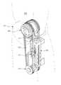
도 3은 로봇용 관절 구동장치의 외관 사시도이다.
도 4는 도 3의 정면도이다.
도 5는 도 3의 분해 사시도이다.
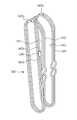
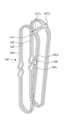
도 6a 및 도 6b는 방향을 달리한 케이블의 연결 상태도이다.
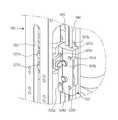
도 7은 출력 풀리 부분을 확대한 확대 사시도이다.
도 8은 도 7의 측면도이다.
도 9는 이동부재와 볼 스크류부 프레임의 결합을 나타내는 도면이다.
도 10은 이동부재를 나타내는 도면이다.
도 11은 이동부재 내부의 케이블과의 결합 상태를 나타내는 도면이다.1 is a front view showing an appearance of a humanoid robot according to an embodiment of the present invention.
Fig. 2 is a schematic perspective view schematically showing the configuration of the humanoid robot of Fig. 1. Fig.
3 is an external perspective view of a joint drive device for a robot.
4 is a front view of Fig.
5 is an exploded perspective view of Fig.
6A and 6B are connection states of cables with different directions.
7 is an enlarged perspective view showing an enlarged view of the output pulley portion.
Fig. 8 is a side view of Fig. 7. Fig.
9 is a view showing the combination of the moving member and the ball screw sub frame.
10 is a view showing the moving member.
11 is a view showing a state of engagement with a cable inside the moving member.
이하에서는 본 발명에 따른 바람직한 실시예를 첨부된 도면을 참조하여 상세히 설명한다.Hereinafter, preferred embodiments of the present invention will be described in detail with reference to the accompanying drawings.
도 1은 본 발명의 일 실시예에 따른 인간형 로봇의 외관을 도시한 정면도이고, 도 2는 도 1의 인간형 로봇의 구성을 개략적으로 도시한 개략 사시도이다.FIG. 1 is a front view showing the appearance of a humanoid robot according to an embodiment of the present invention, and FIG. 2 is a schematic perspective view schematically showing a configuration of the humanoid robot of FIG.
도 1 및 도 2에 도시된 바와 같이, 인간형 로봇(1)(이하에서는 간단히 '로봇'이라 한다)은 동체(胴體)(10)와, 동체(10)의 상부 양측에 연결되는 팔(20R, 20L)과, 동체(10)의 상단부에 연결되는 머리(30)와, 동체(10)의 하부 양측에 연결되는 다리(40R, 40L)를 구비한다. 양팔(20R, 20L)은 어깨관절 어셈블리(210R, 210L)를 통해 동체(10)에 연결되고, 머리(30)는 목(50)을 통해 동체(10)에 연결된다. 참조 부호에서 "R", "L"은 각각 우측과 좌측을 나타낸다.1 and 2, a humanoid robot 1 (hereinafter, simply referred to as a robot) includes a
동체(10)의 내부는 커버(11)에 의해 보호된다. 동체(10)에는 제어유닛(12), 배터리(13) 및 경사센서(14)가 설치될 수 있다. 경사센서(14)는 연직축에 대한 동체(10)의 경사각도와 그 각속도 등을 검출한다.The inside of the
동체(10)는 가슴부(10a)와 허리부(10b)로 분할될 수 있으며, 가슴부(10a)와 허리부(10b) 사이에는 가슴부(10a)가 허리부(10b)에 대해 상대 회전할 수 있도록 관절(15)이 설치될 수 있다. 도 2에서는 동체(10)를 동체링크로서 간략히 도시하였다.The
양측 팔(20R, 20L)은 상박링크(21), 하박링크(22) 및 손(23)을 구비한다. 상박링크(21)는 어깨관절 어셈블리(210)를 통해 동체(10)에 연결된다. 상박링크(21)와 하박링크(22)는 팔꿈치관절부(220)를 통해 서로 연결되고, 하박링크(22)와 손(23)은 손목관절부(230)를 통해 서로 연결된다.Both
팔꿈치관절부(220)는 피치(pitch) 방향의 회전관절(221)과, 요(yaw) 방향의 회전관절(222)을 포함하여 2자유도를 가지고, 손목관절부(230)는 피치 방향의 회전관절(231)과 롤(roll) 방향의 회전관절(232)을 포함하여 2자유도를 가질 수 있다.The elbow
손(23)에는 5개의 손가락(23a)이 설치된다. 각각의 손가락(23a)에는 모터에 의해 구동되는 다수의 관절(미도시)들이 설치될 수 있다. 손가락(23a)은 팔(20)의 움직임에 연동하여 물건을 파지하거나 특정 방향을 가리키는 것과 같은 다양한 동작을 실행한다.The
어깨관절 어셈블리(210R, 210L)는 동체(10)의 양측에 장착되어 양팔(20R, 20L)을 동체(10)에 연결한다. 두 어깨관절 어셈블리(210R, 210L)는 로봇(1)의 동체(10)와 팔(20R, 20L) 사이에 배치되어 팔(20R, 20L)을 움직인다.The shoulder
머리(30)에는 로봇(1)의 시각으로서 기능하는 카메라(31)와, 청각으로서 기능하는 마이크로폰(32)이 설치될 수 있다.The
머리(30)는 목관절부(310)를 통해 동체(10)와 연결된다. 목관절부(310)는 요 방향의 회전관절(311), 피치 방향의 회전관절(312) 및 롤 방향의 회전관절(313)을 포함하여 3자유도를 가질 수 있다.The
목관절부(310)의 각각의 회전관절(311)(312)(313)에는 머리 회전용 모터들(미도시)이 연결된다. 제어유닛(12)은 각각의 모터들을 제어하여 회전관절들(311)(312)(313)을 적정 각도로 구동함으로써 머리(30)를 원하는 방향으로 움직일 수 있다.Head rotation motors (not shown) are connected to the
양측 다리(40R, 40L)는 각각 대퇴 링크(41), 하퇴 링크(42) 및 발(43)을 포함한다. 대퇴 링크(41)는 대퇴 관절부(410)를 통해 동체(10)에 연결된다. 대퇴 링크(41)와 하퇴 링크(42)는 무릎 관절부(420)룰 통해 서로 연결되고, 하퇴 링크(42)와 발(43)은 발목(ankle) 관절부(430)를 통해 서로 연결된다.Both
대퇴 관절부(410)는 3자유도를 가진다. 구체적으로 대퇴 관절부(410)는 요(yaw) 방향(Z축 주위의 회전)의 회전관절(411)과, 피치(pitch) 방향(Y축 주위의 회전)의 회전관절(413)과, 롤(roll) 방향(X축 주위의 회전)의 회전관절(414)을 가질 수 있다. 대퇴 관절부(410) 중에서 피치 방향의 회전관절(413)과 롤 방향의 회전관절(414)은 엉덩이 관절부(412)를 구성할 수 있다.The femoral joint 410 has three degrees of freedom. Specifically, the femoral joint 410 includes a rotary joint 411 in the yaw direction (rotation around the Z axis), a rotary joint 413 in the pitch direction (rotation about the Y axis) roll direction (rotation around the X axis). The pitch joint 413 and the
무릎(knee) 관절부(420)는 피치 방향의 회전관절(421)을 포함하여 1자유도를 가진다. 발목 관절부(430)는 피치 방향과 롤 방향의 회전관절(431)(432)을 포함하여 2자유도를 가진다.The knee
무릎 관절부(420)는 피치 방향의 회전관절(421)을 포함하여 1자유도를 가진다. 발목 관절부(430)는 피치 방향과 롤 방향의 회전관절(431)(432)을 포함하여 2자유도를 가진다.The knee
이와 같이, 각각의 다리(40R, 40L)에는 세 관절부에 대해 6개의 회전관절이 마련되므로, 다리 전체에 대해서는 12개의 회전관절이 마련된다. 도면에 도시되지는 않았으나, 각각의 다리(40R, 40L))에는 각 회전관절을 구동하는 모터들이 설치된다. 제어유닛(12)은 다리(40R, 40L)에 마련된 모터들을 적절히 제어함으로써 로봇(1)의 보행을 비롯하여 다리(40R, 40L)의 다양한 동작을 구현할 수 있다.As described above, since each of the
한편, 양측 다리(40R, 40L)에서 발(43)과 발목 관절부(430)의 사이에는 다축 F/T센서(Multi-Axis Force and Torque Sensor)(44)가 각각 설치된다. 다축 F/T센서(44)는 발(43)로부터 전달되는 힘의 3방향 성분(Fx, Fy, Fz)과 모멘트의 3방향 성분(Mx, My, Mz)을 측정함으로써 발(43)의 착지 여부 및 발(43)에 가해지는 하중을 검출한다.
On the other hand, a multi-axial force and
이하에서는 이러한 로봇의 여러 관절부 중 적어도 하나에 사용되는 로봇 관절 구동장치(500)에 대해 설명한다.Hereinafter, a robot
도 3은 로봇용 관절 구동장치의 외관 사시도이고, 도 4는 도 3의 정면도이며, 도 5는 도 3의 분해 사시도이고, 도 6a 및 도 6b는 방향을 달리한 케이블의 연결 상태도이며, 도 7은 출력 풀리 부분을 확대한 확대 사시도이고, 도 8은 도 7의 측면도이며, 도 9는 이동부재와 볼 스크류부 프레임의 결합을 나타내는 도면이고, 도 10은 이동부재를 나타내는 도면이며, 도 11은 이동부재 내부의 케이블과의 결합 상태를 나타내는 도면이다.3 is an exploded perspective view of Fig. 3, Figs. 6A and 6B are connection state diagrams of cables with different directions, Fig. 7 is an exploded perspective view of Fig. Fig. 8 is a side view of Fig. 7, Fig. 9 is a view showing the combination of the moving member and the ball screw subframe, Fig. 10 is a view showing the moving member, and Fig. Fig. 8 is a view showing a state of engagement with a cable inside the movable member.
도 3 내지 도 5에 도시된 바와 같이, 로봇용 관절 구동장치(500)는 정, 역방향으로 회전 가능하도록 마련되는 구동모터(510)와, 구동모터(510)의 구동력을 전달받아 직선 운동하는 이동부재(520)와, 이동부재(520)가 나사 결합되는 볼 스크류부(535)와, 이동부재(520)의 양방향에서 연결되는 케이블(cable)(540)과, 케이블(540)의 일측부와 접촉하여 회전하는 아이들 풀리(550)와, 케이블(540)의 타측부와 접촉하여 회전하며 관절부(501)를 직접 구동하는 출력 풀리(560)를 포함한다.3 to 5, the
구동모터(510)는 로봇용 관절 구동장치(500)를 구동하기 위한 구동력을 제공한다. 구동모터(510)의 일측은 볼 스크류부(535)와 구동벨트(515)에 의해 연결되며, 구동모터(510)의 회전력은 구동벨트(515)를 통해 볼 스크류부(535)로 전달되어 볼 스크류부(535)를 회전시키게 된다.The driving
볼 스크류부(535)는 구동모터(510)에 의해 회전하게 되며, 이동부재(520)가 결합되도록 나사가 형성된 나사부(537)를 포함한다.The ball screw portion 535 is rotated by the driving
이동부재(520)는 볼 스크률부(535)가 회전하면, 나사부(537)를 따라 상하로 직선 운동하게 된다. 즉, 구동모터(510)의 정, 역방향 회전 운동이 이동부재(520)에 전달되어 상하 직선운동으로 바뀌게 된다.When the ball screw portion 535 rotates, the moving
이동부재(520)가 결합된 볼 스크류부(535)는 볼 스크류부 프레임(590)에 결합된다. 볼 스크류부 프레임(590) 내부에서 볼 스크류부(535)는 정, 역 방향으로 회전하고, 그에 따라 이동부재(520)는 상하 방향으로 직선 운동한다.The ball screw portion 535 to which the moving
이동부재(520)의 양측 상하 방향으로는 케이블(540)이 연결된다. 케이블(540)은 구동모터(510)의 구동력으로 관절부(501)를 회전시킬 수 있도록 소정의 장력을 유지하면서 출력 풀리(560)와 아이들 풀리(550)에 연결된다. 케이블(540)은 바람직하게 스틸(steel)재질로 마련되며, 원반형의 출력 풀리(560)와 아이들 풀리(550)를 감싸도록 배치된다.A
이상에서 설명한 것처럼, 로봇용 관절 구동장치(500)의 전체적인 동작은 구동모터(510)가 정, 역 방향으로 회전하면 볼 스크류부(535)도 함께 회전하고, 그에 따라 이동부재(520)는 상하 방향으로 직선 운동하여 케이블(540)을 상하 방향으로 움직이게 된다. 케이블(540)의 이동은 출력 풀리(560) 및 아이들 풀리(550)를 회전시켜서 출력 풀리(560)에 연결된 관절부(501)가 정, 역 방향으로 회전 구동되는 것이다.As described above, the overall operation of the joint drive device for a
도 6a 및 도 6b에 도시된 바와 같이, 케이블(540)은 1줄의 케이블(540)로 폐루프(closed loop)를 형성하며, 폐루프(closed loop)를 형성하기 위해 1줄 케이블(540)의 양단부(540a, 540b)는 케이블(540)을 압착하도록 형성되는 연결 루프 슬리브(546)에 의해 연결된다. 즉, 케이블(540)의 양단부(540a, 540b)가 연결 루프 슬리브(546)에 의해 연결되어 고정된다.6A and 6B, the
케이블(540)은 아이들 풀리(550), 이동부재(520) 및 출력 풀리(560) 사이에서 적어도 1회 병렬로 연결된다. 본 발명의 일 실시예의 케이블(540)은 일측에서 출력 풀리(560)와 아이들 풀리(550) 사이에 형성되는 제1라인(line)(541)과, 제1라인(541)의 측면에 병렬로 마련되는 제2라인(542)과, 제2라인(542)의 측면에 병렬로 마련되는 제3라인(543)과, 제3라인(543)의 측면에 병렬로 마련되는 제4라인(544)을 포함한다.The
이렇게 케이블(540)을 병렬로 연결시키는 이유는 로봇용 관절 구동장치(500)의 회전 강성(Torsional Stiffness)을 크게 하도록 하기 위해서이다. 회전 강성(Torsional Stiffness)은 외부에서 정지상태의 관절부(501)에 외력이 가해졌을 때 외력에 대해 관절부(501)가 움직이는 정도로 표현할 수 있다. 회전 강성(Torsional Stiffness)이 클수록 외력에 대해 관절부(501)가 덜 움직인다는 의미이다.The reason for connecting the
로봇용 관절 구동장치(500)에서 회전 강성(Torsional Stiffness)을 크게 할 수 있는 방법으로, 출력 풀리(560) 및 아이들 풀리(550)의 지름을 크게하는 방안과 케이블(540)의 자유길이를 짧게 하는 방안을 고려할 수 있다, 하지만, 출력 풀리(560) 및 아이들 풀리(550)의 지름을 크게 하면 전체적인 로봇용 관절 구동장치(500)의 크기가 커지는 문제가 있고, 케이블(540)의 자유길이를 짧게 하면 볼 스크류부(535)의 길이도 짧아지게 되어 관절부(501)의 가동각이 작아지는 문제가 있다. 본 발명의 일 실시예에서는 이러한 문제를 케이블(540)을 복수회 병렬 연결시킴으로써 해결하였다. 케이블(540)을 복수회 병렬 연결시켜서 회전 강성(Torsional Stiffness)이 커지도록 하는 방법은 여러 개의 스프링을 병렬로 연결시켜 스프링 상수(Spring Constant)가 커지도록 하는 것과 같은 원리이다.A method of increasing the diameter of the
도 7 및 도 8에 도시된 바와 같이, 출력 풀리(560)는 케이블(540)과의 슬립 현상이 방지되도록 케이블 고정부(562)를 포함한다.As shown in FIGS. 7 and 8, the
케이블 고정부(562)는 케이블(540)이 출력 풀리(560)의 축 방향과 평행하게 배치되도록 가이드 하는 케이블 가이드 브라켓(563a, 563b)을 포함한다. 즉, 출력 풀리(560)와 접촉하며, 제2라인(542)과 제3라인(543)을 연결하는 부분의 케이블(540)을 케이블 가이드 브라켓(563a, 563b)에 형성된 홈을 따라 배치되도록 하여 출력 풀리(560)와 케이블(540) 사이의 마찰력이 커지도록 하였다.The
또한, 케이블 고정부(562)은 케이블(540)을 출력 풀리(560)에 고정시키기 위한 스페이서(565a, 565b)를 포함한다. 출력 풀리(560)와 접촉하는 제1라인(541)과 제4라인(544)의 케이블(540) 부위에는 케이블(540)을 압착하도록 형성되는 고정 루프 슬리브(loop sleeve)(547a, 547b)가 끼워지고, 스페이서(565a, 565b)는 고정 루프 슬리브(547a, 547b)가 출력 풀리(560)에 고정되도록 형성된다. 즉, 출력 풀리(560)의 루프 슬리브 홈(567a, 567b) 일측에 경사면(566a, 566b)이 형성된 스페이서(565a, 565b)가 접착제로 접착되고, 스페이서(565a, 565b)와 접촉하면서 고정 루프 슬리브(547a, 547b)가 끼워지는 것이다. 이 때 케이블(540)의 프리텐션(pretension)으로 인해 고정 루브 슬리브(547a, 547b)는 루프 슬리브 홈(567a, 567b)에 고정된다.The
도 9 내지 도 11을 참조하여, 이동부재(520)와 볼 스류류부 프레임(590)의 결합 관계 및 이동부재(520)와 케이블(540)의 결합 관계를 설명한다.9 to 11, the engagement relationship between the moving
볼 스크류부 프레임(590)은 이동부재(520)의 회전이 방지되도록 가이드하는 가이드 슬롯(guide slot)(592)을 포함한다. 가이드 슬롯(592)은 상하 길이방향으로 형성되어 이동부재(520)가 상하 방향 운동 만을 하게 하고, 볼 스크류부(535)의 회전 운동에 의해서는 회전하지 않도록 하는 역할을 한다.The ball
가이드 슬롯(592)에는 이동부재(520)의 전면에 형성된 가이드 베어링(527a, 527b)이 끼워져 이동하게 된다. 가이드 베어링(527a, 527b)은 이동부재(520)에 일체로 형성되므로, 이동부재(520)도 가이드 베어링(527a, 527b)의 움직임에 따라 함께 움직이게 된다.
이동부재(520)는 몸체를 형성하며 케이블(540)이 결합되는 장착 블럭(block)(522a, 522b)을 포함한다. 장착 블럭(522a, 522b)은 전면 장착 블럭(522a)과 후면 장착 블록(522b)의 결합으로 형성된다.Moving
장착 블럭(522a, 522b)은 케이블(540)이 결합될 수 있도록 마련되는 케이블 결합부(521a, 521b, 521c, 521d)를 포함한다. 케이블 결합부(521a, 521b, 521c, 521d)는 케이블(540)이 병렬로 걸리도록 장착 블럭(522a, 522b)에 결합되는 제1가이드 핀(guide pin)(524a, 524b, 524c, 524d)과, 케이블(540) 사이의 간격이 줄어들도록 장착 블럭(522a, 522b)에 결합되는 제2가이드 핀(525a, 525b, 525c, 525d, 525e, 525f, 525g, 525h)을 포함한다.The mounting
케이블(540)은 제1가이드 핀(524a, 524b, 524c, 524d)에 걸려 고리 모양의 형상을 형성하게 되고, 제2가이드 핀(525a, 525b, 525c, 525d, 525e, 525f, 525g, 525h)에 의해 병렬로 배치된 케이블(540) 사이의 간격이 좁아진다. 이 때 제1가이드 핀(524a, 524b, 524c, 524d) 및 제2가이드 핀(525a, 525b, 525c, 525d, 525e, 525f, 525g, 525h)은 그 단면 형상을 원형으로 마련하여, 케이블(540)과의 접촉 부위에서 마모가 일어나지 않도록 하며, 케이블(540)이 곡률을 자연스럽게 형성하도록 한다. 그리고, 케이블(540)을 제1가이드 핀(524a, 524b, 524c, 524d) 및 제2가이드 핀(525a, 525b, 525c, 525d, 525e, 525f, 525g, 525h)을 이용하여 장착 블럭(522a, 522b)에 결합시키면 자연스럽게 병렬로 제1라인(541), 제2라인(542), 제3라인(543), 제4라인(544)이 형성된다.The
이하에서는 본 발명의 일 실시예에 따른 로봇용 관절 구동장치(500)의 케이블 연결방법에 대해 설명한다.Hereinafter, a cable connection method of the
케이블(540) 연결방법은 1줄의 케이블(540)이 폐루프(closed loop)를 이루도록 양단부(540a, 540b)를 연결 루프 슬리브(loop sleeve)(546)로 연결하는 매듭 단계와, 케이블(540)을 아이들 풀리(550), 이동부재(520) 및 출력 풀리(560) 사이에 적어도 1회 병렬로 연결하는 병렬 배치 단계를 거치게 된다.The method of connecting the
그리고, 케이블(540)과 출력 풀리(560)와의 슬립 현상이 방지되도록 출력 풀리(560)의 축 방향과 평행하게 케이블(540)을 배치하는 슬립 방지 단계를 거친다.The
마지막으로, 케이블(540)에 끼워진 고정 루프 슬리브(547a, 547b)를 케이블(540)의 프리텐션(pretension)을 이용하여 출력 풀리(560)에 고정시키는 케이블 고정 단계를 거친다.Finally, the fixed
이러한 과정을 거쳐 케이블(540)은 제1라인(541), 제2라인(542), 제3라인(543), 제4라인(544)의 병렬 형태로 마련된다.The
이상에서 설명한 로봇용 관절 구동장치(500)는 케이블(540)을 병렬로 연결시켜 관절부(501)의 회전 강성이 커지게 되었고, 출력 풀리(560)에 케이블 고정부(562)를 마련하여 출력 풀리(560)에서의 슬립(slip) 현상이 방지되도록 하였다.The above-described
또한, 볼 스크류부(535)와 이동부재(520) 및 볼 스크류부 프레임(590)의 구조 개선으로 인해 로봇용 관절 구동장치(500)의 제조 원가가 절감되고, 전체적인 크기가 작아졌다.In addition, the manufacturing cost of the
이상에서는 특정의 실시예에 대하여 도시하고 설명하였다. 그러나, 상기한 실시예에만 한정되지 않으며, 발명이 속하는 기술분야에서 통상의 지식을 가진 자라면 이하의 청구범위에 기재된 발명의 기술적 사상의 요지를 벗어남이 없이 얼마든지 다양하게 변경실시할 수 있을 것이다.The foregoing has shown and described specific embodiments. However, the present invention is not limited to the above-described embodiments, and various changes and modifications may be made without departing from the technical idea of the present invention described in the claims below .
1 : 인간형 로봇500 : 로봇용 관절 구동장치
510 : 구동모터520 : 이동부재
535 : 볼 스크류부540 : 케이블
550 : 아이들 풀리560 : 출력 풀리1: Humanoid robot 500: Joint drive device for robot
510: driving motor 520: moving member
535: ball screw portion 540: cable
550: idler pulley 560: output pulley
Claims (24)
Translated fromKorean상기 구동모터의 구동력을 전달받아 직선 운동하는 이동부재와,
상기 이동부재의 양방향에서 연결되는 케이블(cable)로서, 상기 케이블은 폐루프(closed loop)를 형성하는 1 줄의 케이블로 형성되는 케이블과,
상기 케이블의 일측부와 접촉하여 회전하는 아이들 풀리(idle pulley)와,
상기 케이블의 타측부와 접촉하여 회전하며 관절부를 직접 구동하는 출력 풀리를 포함하고,
상기 케이블은,
상기 아이들 풀리, 이동부재 및 출력풀리에 감겨져서 나란하도록 연결되되, 상기 케이블은 일측에서 상기 출력 풀리와 아이들 풀리 사이에 형성되는 제1라인과, 상기 제1라인의 측면에 나란하게 마련되는 제2라인과, 상기 제2라인의 측면에 나란하게 마련되는 제3라인과, 상기 제3라인의 측면에 나란하게 마련되는 제4라인을 포함하고,
상기 케이블은 상기 케이블을 압착하도록 형성되는 연결루프 슬리브(loop sleeve)에 의해 폐루프(closed loop)를 형성하며 연결되는 것을 특징으로 하는 로봇용 관절 구동장치.A drive motor provided so as to be rotatable in forward and reverse directions,
A moving member which is linearly moved to receive the driving force of the driving motor,
A cable connected in both directions of the moving member, the cable being formed of a single line of cables forming a closed loop,
An idle pulley rotating in contact with one side of the cable,
And an output pulley that rotates in contact with the other side of the cable and directly drives the joint,
The cable,
A first line formed between the output pulley and the idle pulley at one side and a second line formed at a side of the idle pulley, the moving member and the output pulley, A third line arranged in parallel with a side surface of the second line and a fourth line arranged in parallel with a side surface of the third line,
Wherein the cable is connected to a closed loop by a loop sleeve formed to compress the cable.
상기 출력 풀리는 상기 케이블과의 슬립(slip) 현상을 방지하기 위한 케이블 고정부를 포함하는 것을 특징으로 하는 로봇용 관절 구동장치.The method according to claim 1,
And a cable fixing part for preventing the output pulley from slipping with the cable.
상기 케이블 고정부는 상기 케이블이 상기 출력 풀리의 축 방향과 평행하게 배치되도록 가이드 하는 케이블 가이드 브라켓(bracket)을 포함하는 것을 특징으로 하는 로봇용 관절 구동장치.5. The method of claim 4,
Wherein the cable fixing portion includes a cable guide bracket for guiding the cable so as to be parallel to the axial direction of the output pulley.
상기 출력 풀리와 접촉하는 상기 케이블의 부위에는 상기 케이블을 압착하도록 형성되는 고정 루프 슬리브(loop sleeve)가 끼워지고, 상기 케이블 고정부는 상기 고정 루프 슬리브가 상기 출력 풀리에 고정되도록 하는 스페이서(spacer)를 포함하는 것을 특징으로 하는 로봇용 관절 구동장치.5. The method of claim 4,
A portion of the cable in contact with the output pulley is fitted with a loop sleeve formed to compress the cable, and the cable fixing portion includes a spacer for fixing the fixed loop sleeve to the output pulley And the joint driving device for a robot.
상기 이동부재가 나사 결합되는 볼 스크류부를 더 포함하는 것을 특징으로 하는 로봇용 관절 구동장치.The method according to claim 1,
Further comprising a ball screw portion to which the moving member is screwed.
상기 볼 스크류부가 결합되는 볼 스크류부 프레임을 더 포함하고,
상기 볼 스크류부 프레임은 상기 이동부재의 회전이 방지되도록 가이드 하는 가이드 슬롯(guide slot)을 포함하는 것을 특징으로 하는 로봇용 관절 구동장치.8. The method of claim 7,
And a ball screw sub frame coupled with the ball screw unit,
Wherein the ball screw subframe includes a guide slot for guiding the rotation of the moving member to be prevented.
상기 이동부재는 상기 가이드 슬롯에 끼워져 이동하는 적어도 하나의 가이드 베어링을 포함하는 것을 특징으로 하는 로봇용 관절 구동장치.9. The method of claim 8,
Wherein the moving member includes at least one guide bearing which is inserted and moved in the guide slot.
상기 이동부재는,
상기 이동부재의 몸체를 형성하며 상기 케이블이 결합되는 장착 블럭(block)을 포함하고,
상기 장착 블럭은,
상기 케이블이 결합될 수 있도록 마련되는 케이블 결합부를 포함하는 것을 특징으로 하는 로봇용 관절 구동장치.The method according to claim 1,
The moving member
And a mounting block to form the body of the moving member and to which the cable is coupled,
The mounting block includes:
And a cable coupling portion provided to allow the cable to be coupled.
상기 케이블 결합부는 상기 케이블이 병렬로 걸리도록 상기 장착 블럭에 결합되는 제1가이드 핀(guide pin)과, 상기 케이블 사이의 간격이 줄어들도록 상기 장착 블럭에 결합되는 제2가이드 핀을 포함하는 것을 특징으로 하는 로봇용 관절 구동장치.11. The method of claim 10,
Wherein the cable coupling portion includes a first guide pin coupled to the mounting block so that the cable is juxtaposed in parallel and a second guide pin coupled to the mounting block such that an interval between the cables is reduced, And a joint drive device for a robot.
상기 관절 구동장치는 정방향, 역방향으로 회전 가능하도록 마련되는 구동모터와,
상기 구동모터의 구동력을 전달받아 직선 운동하는 이동부재와,
상기 이동부재의 양방향에서 연결되는 케이블로서, 상기 케이블은 폐루프(closed loop)를 형성하는 1 줄의 케이블로 형성되는 케이블과,
상기 케이블의 일측부와 접촉하여 회전하는 아이들(idle) 풀리와,
상기 케이블의 타측부와 접촉하여 회전하며 상기 관절부를 직접 구동하는 출력 풀리를 포함하고,
상기 케이블은,
상기 아이들 풀리, 이동부재 및 출력풀리에 감겨져서 나란하도록 연결되되, 상기 케이블은 일측에서 상기 출력 풀리와 아이들 풀리 사이에 형성되는 제1라인과, 상기 제1라인의 측면에 나란하게 마련되는 제2라인과, 상기 제2라인의 측면에 나란하게 마련되는 제3라인과, 상기 제3라인의 측면에 나란하게 마련되는 제4라인을 포함하고,
상기 케이블은 1줄의 케이블로 형성되되, 상기 1줄 케이블의 양단부는 상기 케이블을 압착하도록 형성되는 연결루프 슬리브(loop sleeve)에 의해 폐루프(closed loop)를 형성하며 연결되는 것을 특징으로 하는 로봇.A robot including a joint drive device for driving a joint part of a robot,
The joint drive device includes a drive motor provided to be rotatable in forward and reverse directions,
A moving member which is linearly moved to receive the driving force of the driving motor,
A cable connected in both directions of the moving member, wherein the cable comprises a cable formed by a single line of cables forming a closed loop,
An idle pulley rotating in contact with one side of the cable,
And an output pulley that rotates in contact with the other side of the cable and directly drives the joint,
The cable,
A first line formed between the output pulley and the idle pulley at one side and a second line formed at a side of the idle pulley, the moving member and the output pulley, A third line arranged in parallel with a side surface of the second line and a fourth line arranged in parallel with a side surface of the third line,
Wherein the cable is formed by a single line of cables, and both ends of the single-line cable are connected by forming a closed loop by a loop sleeve formed to press the cable. .
상기 출력 풀리는 상기 케이블과의 슬립(slip) 현상을 방지하기 위한 케이블 고정부를 포함하는 것을 특징으로 하는 로봇.13. The method of claim 12,
And a cable fixing part for preventing the output pulley from slipping with the cable.
상기 케이블 고정부는 상기 케이블이 상기 출력 풀리의 축 방향과 평행하게 배치되도록 가이드 하는 케이블 가이드 브라켓(bracket)을 포함하는 것을 특징으로 하는 로봇.15. The method of claim 14,
Wherein the cable fixing portion includes a cable guide bracket for guiding the cable so as to be disposed parallel to the axial direction of the output pulley.
상기 출력 풀리와 접촉하는 상기 케이블의 부위에는 상기 케이블을 압착하도록 형성되는 고정 루프 슬리브(loop sleeve)가 끼워지고, 상기 케이블 고정부는 상기 고정 루프 슬리브가 상기 출력 풀리에 고정되도록 하는 스페이서(spacer)를 포함하는 것을 특징으로 하는 로봇.15. The method of claim 14,
A portion of the cable in contact with the output pulley is fitted with a loop sleeve formed to compress the cable, and the cable fixing portion includes a spacer for fixing the fixed loop sleeve to the output pulley Wherein the robot is a robot.
상기 이동부재가 나사 결합되는 볼 스크류부를 더 포함하는 것을 특징으로 하는 로봇.13. The method of claim 12,
Further comprising a ball screw portion to which the moving member is screwed.
상기 볼 스크류부가 결합되는 볼 스크류부 프레임을 더 포함하고,
상기 볼 스크류부 프레임은 상기 이동부재의 회전이 방지되도록 가이드 하는 가이드 슬롯(guide slot)을 포함하는 것을 특징으로 하는 로봇.18. The method of claim 17,
And a ball screw sub frame coupled with the ball screw unit,
Wherein the ball screw subframe includes a guide slot for guiding rotation of the moving member.
상기 이동부재는 상기 가이드 슬롯에 끼워져 이동하는 적어도 하나의 가이드 베어링을 포함하는 것을 특징으로 하는 로봇.19. The method of claim 18,
And the moving member includes at least one guide bearing that moves in the guide slot.
상기 이동부재는 몸체를 형성하며 상기 케이블이 결합되는 장착 블럭(block)을 포함하고, 상기 장착 블럭은 상기 케이블이 결합될 수 있도록 마련되는 케이블 결합부를 포함하는 것을 특징으로 하는 로봇.13. The method of claim 12,
Wherein the moving member includes a block for forming a body and to which the cable is coupled, and the mounting block includes a cable coupling portion to which the cable is coupled.
상기 케이블 결합부는 상기 케이블이 병렬로 걸리도록 상기 장착 블럭에 결합되는 제1가이드 핀(guide pin)과, 상기 케이블 사이의 간격이 줄어들도록 상기 장착 블럭에 결합되는 제2가이드 핀을 포함하는 것을 특징으로 하는 로봇.21. The method of claim 20,
Wherein the cable coupling portion includes a first guide pin coupled to the mounting block so that the cable is juxtaposed in parallel and a second guide pin coupled to the mounting block such that an interval between the cables is reduced, .
1줄의 케이블이 폐루프(closed loop)를 이루도록 양단부를 연결 루프 슬리브(loop sleeve)로 연결하는 매듭 단계;와,
상기 케이블을 상기 아이들 풀리, 이동부재 및 출력풀리 에 감겨져서 나란하도록 연결하되, 상기 출력풀리와 아이들 풀리 사이에 형성되는 제1라인과, 상기 제1라인의 측면에 나란하게 마련되는 제2라인과, 상기 제2라인의 측면에 나란하게 마련되는 제3라인과, 상기 제3라인의 측면에 나란하게 마련되는 제4라인을 형성하도록 연결하는 병렬 배치 단계;를 포함하는 것을 특징으로 하는 로봇용 관절 구동장치의 케이블 연결방법.A cable connected in both directions of the moving member, an idle pulley rotating in contact with one side of the cable, and an output pulley rotating in contact with the other side of the cable, In the cable connecting method of the present invention,
A knotting step of connecting both ends to a loop sleeve so that one line of cable forms a closed loop,
A first line formed between the output pulley and the idle pulley, and a second line arranged in parallel with a side surface of the first line, and a second line formed between the output pulley and the idle pulley, And a parallel arrangement step of connecting a third line arranged in parallel to a side surface of the second line and a fourth line arranged in parallel to a side surface of the third line, Cable connection method of drive unit.
상기 케이블과 출력 풀리와의 슬립 현상이 방지되도록 상기 출력 풀리의 축 방향과 평행하게 상기 케이블을 배치하는 슬립 방지 단계;를 더 포함하는 것을 특징으로 하는 로봇용 관절 구동장치의 케이블 연결방법.23. The method of claim 22,
Further comprising a slip prevention step of disposing the cable in parallel with an axial direction of the output pulley so as to prevent a slip phenomenon between the cable and the output pulley.
상기 출력 풀리와 접촉하는 상기 케이블의 부위에 상기 케이블을 압착하는 고정 루프 슬리브(loop sleeve)를 끼우고, 상기 고정 루프 슬리브를 상기 케이블의 프리텐션(pretension)을 이용하여 상기 출력 풀리에 고정시키는 케이블 고정 단계;를 더 포함하는 것을 특징으로 하는 로봇용 관절 구동장치의 케이블 연결방법.24. The method of claim 23,
A cable for clamping the cable to a portion of the cable in contact with the output pulley and fixing the fixed loop sleeve to the output pulley using a pre- The method of claim 1, further comprising the step of: fixing the cable.
Priority Applications (2)
| Application Number | Priority Date | Filing Date | Title |
|---|---|---|---|
| KR1020100003518AKR101706094B1 (en) | 2010-01-14 | 2010-01-14 | Robot joint driving apparatus and robot having the same, cable linking method of robot joint driving apparatus |
| US12/987,244US8635929B2 (en) | 2010-01-14 | 2011-01-10 | Robot joint driving apparatus, robot having the same and cable linkage method of robot joint driving apparatus |
Applications Claiming Priority (1)
| Application Number | Priority Date | Filing Date | Title |
|---|---|---|---|
| KR1020100003518AKR101706094B1 (en) | 2010-01-14 | 2010-01-14 | Robot joint driving apparatus and robot having the same, cable linking method of robot joint driving apparatus |
Publications (2)
| Publication Number | Publication Date |
|---|---|
| KR20110083340A KR20110083340A (en) | 2011-07-20 |
| KR101706094B1true KR101706094B1 (en) | 2017-02-14 |
Family
ID=44257457
Family Applications (1)
| Application Number | Title | Priority Date | Filing Date |
|---|---|---|---|
| KR1020100003518AActiveKR101706094B1 (en) | 2010-01-14 | 2010-01-14 | Robot joint driving apparatus and robot having the same, cable linking method of robot joint driving apparatus |
Country Status (2)
| Country | Link |
|---|---|
| US (1) | US8635929B2 (en) |
| KR (1) | KR101706094B1 (en) |
Families Citing this family (37)
| Publication number | Priority date | Publication date | Assignee | Title |
|---|---|---|---|---|
| KR20100077504A (en)* | 2008-12-29 | 2010-07-08 | 삼성전자주식회사 | Robot joint driving apparatus and robot having the same |
| KR20110026935A (en)* | 2009-09-09 | 2011-03-16 | 삼성전자주식회사 | Robot joint drive and robot comprising the same |
| FR2981420B1 (en)* | 2011-10-17 | 2013-11-29 | Commissariat Energie Atomique | ASYMMETRIC ANTI-ROTATION DEVICE AND SCREW JACK WITH SUCH A DEVICE |
| KR102025125B1 (en) | 2012-04-02 | 2019-11-04 | 삼성전자주식회사 | Driving device usable with robot arm and robot arm |
| FR2990485B1 (en)* | 2012-05-09 | 2021-04-23 | Commissariat Energie Atomique | FLEXIBLE DRIVE SHAFT, AND CABLE CYLINDER WITH OFFSET MOTOR USING SUCH A SHAFT |
| FR3002607B1 (en)* | 2013-02-22 | 2016-07-08 | Commissariat A L`Energie Atomique Et Aux Energies Alternatives | VERIN CABLE TOLERANT TO DESALIGNMENTS |
| CN205521410U (en)* | 2013-03-15 | 2016-08-31 | Sri国际公司 | Programmable body augmentation system and platform for body augmentation |
| FR3004230B1 (en)* | 2013-04-05 | 2015-05-15 | Commissariat Energie Atomique | CABLE VERIN FOR INCREASED JOINT DEBATMENT |
| DE112015003875B4 (en)* | 2014-08-25 | 2022-06-23 | Paul Ekas | Shock-absorbing and self-realigning robotic fingers |
| US10046461B2 (en)* | 2014-08-25 | 2018-08-14 | Paul Ekas | Link structure and assembly including cable guide system for robotic mechanical manipulator structure |
| US9475191B1 (en)* | 2014-09-03 | 2016-10-25 | Google Inc. | Robotic leg parallel to a ball screw |
| CN104382722B (en)* | 2014-11-24 | 2017-01-11 | 江苏大学 | Volute spring type flexible and elastic joint applicable to rehabilitation robot |
| KR102346226B1 (en)* | 2015-01-22 | 2022-01-03 | 삼성전자주식회사 | A driving module and a motion assist apparatus comprising thereof |
| US11295506B2 (en) | 2015-09-16 | 2022-04-05 | Tmrw Foundation Ip S. À R.L. | Chip with game engine and ray trace engine |
| CN105459148B (en)* | 2016-01-26 | 2017-06-13 | 哈尔滨工业大学 | A kind of steel wire drive joint with rope stretching point play compensation function |
| JP6220105B1 (en) | 2016-02-10 | 2017-10-25 | 株式会社国際電気通信基礎技術研究所 | Externally driven joint structure |
| US10702441B2 (en) | 2016-05-04 | 2020-07-07 | Ekso Bionics, Inc. | Ball screw and tensile member exoskeleton joint actuation device |
| DE102016007741A1 (en)* | 2016-06-27 | 2017-12-28 | Marcel Reese | The invention relates to the field of exoskeletons, humanoid robots and also their use in teleoperative applications in virtual worlds or the real world |
| TWI592588B (en) | 2016-07-12 | 2017-07-21 | 財團法人工業技術研究院 | Electromagnetic spring and elastic actuator having the same |
| US10253855B2 (en) | 2016-12-15 | 2019-04-09 | Boston Dynamics, Inc. | Screw actuator for a legged robot |
| CN106826920B (en)* | 2017-02-15 | 2019-05-17 | 江苏远卓电气科技有限公司 | A kind of fixed device of the bunch of robot mechanical arm |
| GB2563234B (en)* | 2017-06-06 | 2021-12-08 | Cmr Surgical Ltd | Securing an interface element rail of a robotic surgical instrument interface |
| CN107486850B (en)* | 2017-09-08 | 2020-05-01 | 四川大学 | A variable-stiffness elastic joint for a flexible cable-driven robot |
| CN107972021A (en)* | 2017-12-14 | 2018-05-01 | 杭州娃哈哈精密机械有限公司 | A kind of Multi-shaft mechanical arm |
| CN109960178B (en)* | 2017-12-26 | 2020-10-16 | 深圳市优必选科技有限公司 | Robot and joint motion control method and device thereof |
| CN108247666B (en)* | 2017-12-28 | 2020-12-01 | 中国科学院沈阳自动化研究所 | A parallel light robot joint variable stiffness actuator |
| US11301951B2 (en) | 2018-03-15 | 2022-04-12 | The Calany Holding S. À R.L. | Game engine and artificial intelligence engine on a chip |
| CN110524512B (en)* | 2018-05-23 | 2024-07-02 | 深圳市丞辉威世智能科技有限公司 | Power transmission mechanism and robot |
| CN109623805A (en)* | 2018-12-29 | 2019-04-16 | 上海理工大学 | A kind of flexible linear driving device |
| US11625884B2 (en) | 2019-06-18 | 2023-04-11 | The Calany Holding S. À R.L. | Systems, methods and apparatus for implementing tracked data communications on a chip |
| CN111481402B (en)* | 2020-04-24 | 2022-02-01 | 合肥工业大学 | Knee joint exoskeleton based on rope variable-stiffness multifunctional driver and control method |
| CN112847424B (en)* | 2020-12-24 | 2022-04-19 | 中国科学技术大学 | A stiffness-amplifying rope-driven single-degree-of-freedom joint |
| KR20230123820A (en)* | 2022-02-18 | 2023-08-24 | 코오롱인더스트리 주식회사 | Biodegradable particle, menufacturing method thereof and cosmetic composition comprising the same |
| KR20230124400A (en)* | 2022-02-18 | 2023-08-25 | 현대자동차주식회사 | Power transmission device and robot including the same |
| CN118850218A (en)* | 2023-04-26 | 2024-10-29 | 腾讯科技(深圳)有限公司 | Robot hip joint, control method, device and robot |
| CN116619438B (en)* | 2023-06-05 | 2025-07-25 | 南京航空航天大学 | Variable stiffness joint, working method and control algorithm |
| DE102023135269A1 (en)* | 2023-12-15 | 2025-06-18 | Nanyang Technological University | Rope tensioning device and robot with such a rope tensioning device |
Citations (1)
| Publication number | Priority date | Publication date | Assignee | Title |
|---|---|---|---|---|
| JP2005349489A (en)* | 2004-06-08 | 2005-12-22 | Sharp Corp | Multi-degree-of-freedom multi-fingered hand |
Family Cites Families (24)
| Publication number | Priority date | Publication date | Assignee | Title |
|---|---|---|---|---|
| US640242A (en)* | 1899-03-25 | 1900-01-02 | Robert A Turner | Steam steering-gear. |
| US2660894A (en)* | 1950-11-17 | 1953-12-01 | Gen Motors Corp | Windshield wiper drive apparatus |
| US3202000A (en)* | 1961-10-02 | 1965-08-24 | Int Harvester Co | Slewing mechanism |
| US3466937A (en)* | 1967-01-09 | 1969-09-16 | Gilbert M Motis | Linear to rotational movement converter |
| US3745888A (en)* | 1971-11-24 | 1973-07-17 | Gen Motors Corp | Fluid operated linear motor |
| AT338410B (en)* | 1975-09-18 | 1977-08-25 | Viennatone Gmbh | TRANSMISSION FOR AN ORTHESIS, PROSTHESIS OR DGL. |
| FR2404940A1 (en)* | 1977-09-30 | 1979-04-27 | Cables De Lyon Geoffroy Delore | PROCESS AND DEVICE FOR ENDED ELECTRICAL CABLES WITH COMPRESSED MINERAL INSULATION |
| EP0108657B1 (en)* | 1982-09-25 | 1987-08-12 | Fujitsu Limited | A multi-articulated robot |
| US4804220A (en)* | 1986-01-21 | 1989-02-14 | Rosheim Mark E | Wrist tendon actuator |
| DE3905561C2 (en)* | 1989-02-23 | 1995-04-20 | Rexroth Pneumatik Mannesmann | Working cylinder actuatable by pressure medium |
| US5447403A (en)* | 1990-01-05 | 1995-09-05 | Engler, Jr.; Charles D. | Dexterous programmable robot and control system |
| US5710870A (en)* | 1995-09-07 | 1998-01-20 | California Institute Of Technology | Decoupled six degree-of-freedom robot manipulator |
| US6266844B1 (en)* | 1999-09-13 | 2001-07-31 | Norwood Enterprises, Llc | Vehicle windshield wiper assembly incorporating cable and pulley drive system and remote positioned electric motor |
| US6601468B2 (en)* | 2000-10-24 | 2003-08-05 | Innovative Robotic Solutions | Drive system for multiple axis robot arm |
| DE20117795U1 (en)* | 2001-10-31 | 2002-03-07 | TRW Automotive Electronics & Components GmbH & Co. KG, 78315 Radolfzell | Drive unit for actuating a parking brake in a vehicle |
| US6988440B2 (en)* | 2002-07-18 | 2006-01-24 | Phd, Inc. | Rotary actuator assembly |
| FR2852265B1 (en)* | 2003-03-14 | 2006-02-24 | Commissariat Energie Atomique | INTERMEDIATE SEGMENT OF ARTICULATED ARMS CONTAINING SCREW AND NUT TRANSMISSION |
| FR2852373B1 (en)* | 2003-03-14 | 2005-04-15 | Commissariat Energie Atomique | SCREW TRANSMISSION, NUT AND CABLE |
| JP4315720B2 (en)* | 2003-04-01 | 2009-08-19 | 本田技研工業株式会社 | Cable guides for joints such as robots |
| EP2067581B1 (en)* | 2007-12-05 | 2011-01-12 | Korea Atomic Energy Research Institute | Cable-driven manipulator with a cable compensation device |
| US8821480B2 (en)* | 2008-07-16 | 2014-09-02 | Intuitive Surgical Operations, Inc. | Four-cable wrist with solid surface cable channels |
| KR20100030879A (en)* | 2008-09-11 | 2010-03-19 | 삼성전자주식회사 | Robot hand and humanoid robot having the same |
| CN102256555B (en)* | 2008-12-23 | 2015-09-09 | 马科外科公司 | End effector with release actuator |
| US8052185B2 (en)* | 2009-04-09 | 2011-11-08 | Disney Enterprises, Inc. | Robot hand with humanoid fingers |
- 2010
- 2010-01-14KRKR1020100003518Apatent/KR101706094B1/enactiveActive
- 2011
- 2011-01-10USUS12/987,244patent/US8635929B2/enactiveActive
Patent Citations (1)
| Publication number | Priority date | Publication date | Assignee | Title |
|---|---|---|---|---|
| JP2005349489A (en)* | 2004-06-08 | 2005-12-22 | Sharp Corp | Multi-degree-of-freedom multi-fingered hand |
Also Published As
| Publication number | Publication date |
|---|---|
| US8635929B2 (en) | 2014-01-28 |
| KR20110083340A (en) | 2011-07-20 |
| US20110167945A1 (en) | 2011-07-14 |
Similar Documents
| Publication | Publication Date | Title |
|---|---|---|
| KR101706094B1 (en) | Robot joint driving apparatus and robot having the same, cable linking method of robot joint driving apparatus | |
| CN112476478B (en) | A bionic rope-driven four-degree-of-freedom arm for human-robot collaboration | |
| US8950285B2 (en) | Robot joint driving method, computer-readable medium, device assembly and robot having the same | |
| KR20100082225A (en) | Robot joint driving apparatus and robot having the same | |
| US20090308188A1 (en) | Robot joint driving apparatus and robot having the same | |
| US9314934B2 (en) | Gravity-counterbalanced robot arm | |
| US8443694B2 (en) | Rotary series elastic actuator | |
| US8459139B2 (en) | Robot joint driving apparatus and robot having the same | |
| US8641782B2 (en) | Compact exoskeleton arm support device to compensate for gravity | |
| KR101270031B1 (en) | Weight compensation mechanism and robot arm using the same | |
| US8425363B2 (en) | Robot joint driving apparatus and robot having the same | |
| Whitney et al. | A passively safe and gravity-counterbalanced anthropomorphic robot arm | |
| CN108262763B (en) | Robot joint rigidity-variable actuator | |
| KR20160119960A (en) | Shoulder Joint Assembly of Robot Arm | |
| CN113084864B (en) | A Variable Stiffness Robot Joint Structure | |
| CN113545958A (en) | A shoulder joint rehabilitation robot | |
| KR101749572B1 (en) | Structure of robot joint and robot having the same | |
| CN113967905B (en) | Leg mechanism of exoskeleton robot | |
| CN102302835A (en) | Flexible cable driving unit | |
| KR20160132254A (en) | Joint apparatus and wearable robot having the same | |
| CN119910621B (en) | A compliant back-drive parallel robot and working method | |
| CN111152196B (en) | A multi-axis robotic arm | |
| CN119871365A (en) | Flexible rope driving serial robot based on flexible joints and tension structure | |
| Wilson et al. | Walk and roll robot | |
| CZ302298B6 (en) | Ball joint with at least two degrees of freedom |
Legal Events
| Date | Code | Title | Description |
|---|---|---|---|
| PA0109 | Patent application | Patent event code:PA01091R01D Comment text:Patent Application Patent event date:20100114 | |
| PG1501 | Laying open of application | ||
| A201 | Request for examination | ||
| PA0201 | Request for examination | Patent event code:PA02012R01D Patent event date:20150108 Comment text:Request for Examination of Application Patent event code:PA02011R01I Patent event date:20100114 Comment text:Patent Application | |
| E902 | Notification of reason for refusal | ||
| PE0902 | Notice of grounds for rejection | Comment text:Notification of reason for refusal Patent event date:20160322 Patent event code:PE09021S01D | |
| AMND | Amendment | ||
| E601 | Decision to refuse application | ||
| PE0601 | Decision on rejection of patent | Patent event date:20160929 Comment text:Decision to Refuse Application Patent event code:PE06012S01D Patent event date:20160322 Comment text:Notification of reason for refusal Patent event code:PE06011S01I | |
| AMND | Amendment | ||
| PX0901 | Re-examination | Patent event code:PX09011S01I Patent event date:20160929 Comment text:Decision to Refuse Application Patent event code:PX09012R01I Patent event date:20160523 Comment text:Amendment to Specification, etc. | |
| PX0701 | Decision of registration after re-examination | Patent event date:20161108 Comment text:Decision to Grant Registration Patent event code:PX07013S01D Patent event date:20161031 Comment text:Amendment to Specification, etc. Patent event code:PX07012R01I Patent event date:20160929 Comment text:Decision to Refuse Application Patent event code:PX07011S01I Patent event date:20160523 Comment text:Amendment to Specification, etc. Patent event code:PX07012R01I | |
| X701 | Decision to grant (after re-examination) | ||
| GRNT | Written decision to grant | ||
| PR0701 | Registration of establishment | Comment text:Registration of Establishment Patent event date:20170207 Patent event code:PR07011E01D | |
| PR1002 | Payment of registration fee | Payment date:20170208 End annual number:3 Start annual number:1 | |
| PG1601 | Publication of registration | ||
| FPAY | Annual fee payment | Payment date:20200120 Year of fee payment:4 | |
| PR1001 | Payment of annual fee | Payment date:20200120 Start annual number:4 End annual number:4 | |
| PR1001 | Payment of annual fee | Payment date:20210120 Start annual number:5 End annual number:5 | |
| PR1001 | Payment of annual fee | Payment date:20220112 Start annual number:6 End annual number:6 |