KR101698771B1 - temperature controlling system of battery and controlling method thereof - Google Patents
temperature controlling system of battery and controlling method thereofDownload PDFInfo
- Publication number
- KR101698771B1 KR101698771B1KR1020130005046AKR20130005046AKR101698771B1KR 101698771 B1KR101698771 B1KR 101698771B1KR 1020130005046 AKR1020130005046 AKR 1020130005046AKR 20130005046 AKR20130005046 AKR 20130005046AKR 101698771 B1KR101698771 B1KR 101698771B1
- Authority
- KR
- South Korea
- Prior art keywords
- battery
- inverter
- terminal
- switch
- inductor
- Prior art date
- Legal status (The legal status is an assumption and is not a legal conclusion. Google has not performed a legal analysis and makes no representation as to the accuracy of the status listed.)
- Active
Links
Images


Classifications
- H—ELECTRICITY
- H01—ELECTRIC ELEMENTS
- H01M—PROCESSES OR MEANS, e.g. BATTERIES, FOR THE DIRECT CONVERSION OF CHEMICAL ENERGY INTO ELECTRICAL ENERGY
- H01M10/00—Secondary cells; Manufacture thereof
- H01M10/60—Heating or cooling; Temperature control
- H01M10/61—Types of temperature control
- H01M10/617—Types of temperature control for achieving uniformity or desired distribution of temperature
- H—ELECTRICITY
- H01—ELECTRIC ELEMENTS
- H01M—PROCESSES OR MEANS, e.g. BATTERIES, FOR THE DIRECT CONVERSION OF CHEMICAL ENERGY INTO ELECTRICAL ENERGY
- H01M10/00—Secondary cells; Manufacture thereof
- H01M10/42—Methods or arrangements for servicing or maintenance of secondary cells or secondary half-cells
- H01M10/44—Methods for charging or discharging
- H01M10/443—Methods for charging or discharging in response to temperature
- H—ELECTRICITY
- H01—ELECTRIC ELEMENTS
- H01G—CAPACITORS; CAPACITORS, RECTIFIERS, DETECTORS, SWITCHING DEVICES, LIGHT-SENSITIVE OR TEMPERATURE-SENSITIVE DEVICES OF THE ELECTROLYTIC TYPE
- H01G9/00—Electrolytic capacitors, rectifiers, detectors, switching devices, light-sensitive or temperature-sensitive devices; Processes of their manufacture
- H01G9/0029—Processes of manufacture
- H01G9/0032—Processes of manufacture formation of the dielectric layer
- H—ELECTRICITY
- H01—ELECTRIC ELEMENTS
- H01M—PROCESSES OR MEANS, e.g. BATTERIES, FOR THE DIRECT CONVERSION OF CHEMICAL ENERGY INTO ELECTRICAL ENERGY
- H01M10/00—Secondary cells; Manufacture thereof
- H01M10/60—Heating or cooling; Temperature control
- H01M10/63—Control systems
- H—ELECTRICITY
- H02—GENERATION; CONVERSION OR DISTRIBUTION OF ELECTRIC POWER
- H02J—CIRCUIT ARRANGEMENTS OR SYSTEMS FOR SUPPLYING OR DISTRIBUTING ELECTRIC POWER; SYSTEMS FOR STORING ELECTRIC ENERGY
- H02J3/00—Circuit arrangements for AC mains or AC distribution networks
- H02J3/28—Arrangements for balancing of the load in a network by storage of energy
- H02J3/32—Arrangements for balancing of the load in a network by storage of energy using batteries with converting means
- H—ELECTRICITY
- H02—GENERATION; CONVERSION OR DISTRIBUTION OF ELECTRIC POWER
- H02J—CIRCUIT ARRANGEMENTS OR SYSTEMS FOR SUPPLYING OR DISTRIBUTING ELECTRIC POWER; SYSTEMS FOR STORING ELECTRIC ENERGY
- H02J7/00—Circuit arrangements for charging or depolarising batteries or for supplying loads from batteries
- H02J7/0013—Circuit arrangements for charging or depolarising batteries or for supplying loads from batteries acting upon several batteries simultaneously or sequentially
- H02J7/0024—Parallel/serial switching of connection of batteries to charge or load circuit
- H—ELECTRICITY
- H02—GENERATION; CONVERSION OR DISTRIBUTION OF ELECTRIC POWER
- H02J—CIRCUIT ARRANGEMENTS OR SYSTEMS FOR SUPPLYING OR DISTRIBUTING ELECTRIC POWER; SYSTEMS FOR STORING ELECTRIC ENERGY
- H02J7/00—Circuit arrangements for charging or depolarising batteries or for supplying loads from batteries
- H02J7/007—Regulation of charging or discharging current or voltage
- H02J7/007188—Regulation of charging or discharging current or voltage the charge cycle being controlled or terminated in response to non-electric parameters
- H02J7/007192—Regulation of charging or discharging current or voltage the charge cycle being controlled or terminated in response to non-electric parameters in response to temperature
- H02J7/007194—Regulation of charging or discharging current or voltage the charge cycle being controlled or terminated in response to non-electric parameters in response to temperature of the battery
- H—ELECTRICITY
- H01—ELECTRIC ELEMENTS
- H01M—PROCESSES OR MEANS, e.g. BATTERIES, FOR THE DIRECT CONVERSION OF CHEMICAL ENERGY INTO ELECTRICAL ENERGY
- H01M10/00—Secondary cells; Manufacture thereof
- H01M10/42—Methods or arrangements for servicing or maintenance of secondary cells or secondary half-cells
- H01M10/425—Structural combination with electronic components, e.g. electronic circuits integrated to the outside of the casing
- H01M2010/4271—Battery management systems including electronic circuits, e.g. control of current or voltage to keep battery in healthy state, cell balancing
- H—ELECTRICITY
- H02—GENERATION; CONVERSION OR DISTRIBUTION OF ELECTRIC POWER
- H02J—CIRCUIT ARRANGEMENTS OR SYSTEMS FOR SUPPLYING OR DISTRIBUTING ELECTRIC POWER; SYSTEMS FOR STORING ELECTRIC ENERGY
- H02J7/00—Circuit arrangements for charging or depolarising batteries or for supplying loads from batteries
- H02J7/0029—Circuit arrangements for charging or depolarising batteries or for supplying loads from batteries with safety or protection devices or circuits
- H02J7/0031—Circuit arrangements for charging or depolarising batteries or for supplying loads from batteries with safety or protection devices or circuits using battery or load disconnect circuits
- H—ELECTRICITY
- H02—GENERATION; CONVERSION OR DISTRIBUTION OF ELECTRIC POWER
- H02J—CIRCUIT ARRANGEMENTS OR SYSTEMS FOR SUPPLYING OR DISTRIBUTING ELECTRIC POWER; SYSTEMS FOR STORING ELECTRIC ENERGY
- H02J7/00—Circuit arrangements for charging or depolarising batteries or for supplying loads from batteries
- H02J7/007—Regulation of charging or discharging current or voltage
- H02J7/00711—Regulation of charging or discharging current or voltage with introduction of pulses during the charging process
- H—ELECTRICITY
- H02—GENERATION; CONVERSION OR DISTRIBUTION OF ELECTRIC POWER
- H02J—CIRCUIT ARRANGEMENTS OR SYSTEMS FOR SUPPLYING OR DISTRIBUTING ELECTRIC POWER; SYSTEMS FOR STORING ELECTRIC ENERGY
- H02J7/00—Circuit arrangements for charging or depolarising batteries or for supplying loads from batteries
- H02J7/02—Circuit arrangements for charging or depolarising batteries or for supplying loads from batteries for charging batteries from AC mains by converters
- H02J7/04—Regulation of charging current or voltage
- Y—GENERAL TAGGING OF NEW TECHNOLOGICAL DEVELOPMENTS; GENERAL TAGGING OF CROSS-SECTIONAL TECHNOLOGIES SPANNING OVER SEVERAL SECTIONS OF THE IPC; TECHNICAL SUBJECTS COVERED BY FORMER USPC CROSS-REFERENCE ART COLLECTIONS [XRACs] AND DIGESTS
- Y02—TECHNOLOGIES OR APPLICATIONS FOR MITIGATION OR ADAPTATION AGAINST CLIMATE CHANGE
- Y02E—REDUCTION OF GREENHOUSE GAS [GHG] EMISSIONS, RELATED TO ENERGY GENERATION, TRANSMISSION OR DISTRIBUTION
- Y02E60/00—Enabling technologies; Technologies with a potential or indirect contribution to GHG emissions mitigation
- Y02E60/10—Energy storage using batteries
Landscapes
- Engineering & Computer Science (AREA)
- Power Engineering (AREA)
- Manufacturing & Machinery (AREA)
- Chemical & Material Sciences (AREA)
- Chemical Kinetics & Catalysis (AREA)
- Electrochemistry (AREA)
- General Chemical & Material Sciences (AREA)
- Microelectronics & Electronic Packaging (AREA)
- Automation & Control Theory (AREA)
- Charge And Discharge Circuits For Batteries Or The Like (AREA)
Abstract
Translated fromKoreanDescription
Translated fromKorean본 발명의 실시예는 배터리 온도 제어 시스템에 관한 것으로, 특히 전력 저장 시스템(Energy Storage System)에 구비되는 배터리 온도 제어 시스템 및 그 제어 방법에 관한 것이다.BACKGROUND OF THE
환경 파괴, 자원 고갈 등이 문제되면서, 전력을 저장하고, 저장된 전력을 효율적으로 활용할 수 있는 시스템에 대한 관심이 높아지고 있다. 또한, 이와 함께 태양광, 풍력, 조력 등 무한히 공급되는 천연 자원을 이용하고, 발전 과정에서 공해를 유발하지 않는 신재생 에너지의 중요성이 증대되고 있다.Environmental degradation, resource depletion, etc., there is a growing interest in a system capable of storing electric power and efficiently utilizing stored electric power. In addition, the importance of renewable energy that uses infinitely supplied natural resources such as solar power, wind power, and tidal power and does not cause pollution in the development process is increasing.
전력 저장 시스템은 이와 같은 신재생 에너지, 전력을 저장하는 배터리, 그리고 기존의 계통 전력을 연계시키는 시스템으로서, 최근의 환경 변화에 맞추어 많은 연구 개발이 이루어지고 있다.The power storage system is a system that links the renewable energy, the battery that stores the power, and the power of the existing system, and many researches and developments have been made in accordance with the recent environmental change.
상기 전력 저장 시스템에 구비되는 배터리는 충방전이 가능한 이차전지로 구현되는데, 이러한 배터리는 상온에서는 정상적인 동작이 가능하나, 저온(일 예로 -20℃ 이하)에서는 그 출력이 상온 대비 약 16%정도로 매우 낮은 값을 갖는다.The battery included in the power storage system is a secondary battery capable of charging and discharging. The battery can operate normally at room temperature. However, at a low temperature (for example, below -20 ° C), the output of the battery is about 16% And has a low value.
이에 종래의 경우 상기 배터리의 온도 상승을 위해 히터를 사용하거나, 저항 또는 전자부하에 의한 발열을 사용하는 방법 등이 제안되었다.Accordingly, in the related art, a method of using a heater for increasing the temperature of the battery or using heat generated by a resistor or an electronic load has been proposed.
그러나, 이와 같은 종래의 방법에 의할 경우 배터리의 전력을 소비하게 되어 배터리 사용률이 저하되고, 화재의 위험성이 높아지는 단점이 있다.However, according to the conventional method, power consumption of the battery is consumed, so that the battery usage rate is lowered and the risk of fire is increased.
본 발명의 실시예는 전력 저장 시스템에 스위치를 추가 구성하여 배터리측으로의 충방전 전류 패스를 조절함으로써, 상기 배터리의 온도를 제어할 수 있는 배터리 온도 제어 시스템을 제공함을 그 목적으로 한다.It is an object of the present invention to provide a battery temperature control system capable of controlling the temperature of the battery by additionally providing a switch to the power storage system to regulate charge / discharge current paths to the battery side.
또한, 본 발명의 실시예는 전력 저장 시스템의 동작 중 배터리의 저온 상태 감지 시 계통과의 연결을 끊고 출력단측 인버터의 인덕터를 이용하여 배터리측에 충방전 전류를 발생시킴을 통해 배터리의 온도를 상승시키는 배터리 온도 제어 방법을 제공함에 그 목적이 있다.In an embodiment of the present invention, when the low temperature state of the battery is detected during the operation of the power storage system, the battery is disconnected from the system and the charge / discharge current is generated on the battery side using the inductor of the output side inverter, And a method of controlling the battery temperature.
상기 목적을 달성하기 위하여 본 발명의 실시예에 의한 배터리 온도 제어 시스템은, 전력 저장 시스템에 구비되는 배터리와; 복수의 스위치 및 하나의 컨버터 인덕터로 구성되어 상기 배터리의 전압을 승압 또는 감압하는 컨버터와; 상기 컨버터의 출력 전압을 안정화시키는 제 1, 2캐패시터가 직렬로 연결된 DC 링크부와; 복수의 스위치 및 하나의 인버터 인덕터로 구성되어 입력되는 전압을 변환(inverting)하는 인버터가 포함되며, 상기 인버터는 상기 인버터 인덕터에서 생성된 전류를 상기 배터리 측으로 전달되도록 상기 인버터 인덕터의 일측 단자를 상기 DC 링크부를 구성하는 제 1, 2캐패시터 사이의 노드에 연결하는 스위치가 더 포함된다.According to an aspect of the present invention, there is provided a battery temperature control system including: a battery included in an electric power storage system; A converter configured by a plurality of switches and one converter inductor to step up or down the voltage of the battery; A DC link unit having first and second capacitors serially connected to stabilize the output voltage of the converter; The inverter includes a plurality of switches and an inverter inductor. The inverter includes an inverter for inverting the input voltage. The inverter converts one end of the inverter inductor to the DC And a switch for connecting the node between the first and second capacitors constituting the link portion.
또한, 상기 컨버터는, 상기 배터리의 제 1단자에 연결되는 상기 컨버터 인덕터와; 상기 DC 링크부에 구비된 캐패시터의 제 1단자와 상기 컨버터 인덕터의 제 2단자 사이에 연결되는 제 1스위치와; 상기 컨버터 인덕터의 제 2단자와 상기 배터리의 제 2단자 사이에 연결되는 제 2스위치가 포함된다.The converter further includes: a converter inductor connected to a first terminal of the battery; A first switch connected between a first terminal of the capacitor included in the DC link unit and a second terminal of the converter inductor; And a second switch connected between a second terminal of the converter inductor and a second terminal of the battery.
또한, 상기 배터리의 제 1단자와 상기 DC 링크부에 구비된 제 1캐패시터의 제 1단자 사이에 연결되는 제 3스위치가 더 포함된다.The apparatus further includes a third switch connected between a first terminal of the battery and a first terminal of the first capacitor provided in the DC link unit.
또한, 상기 인버터는 입력되는 전압을 변환하기 위해 구비되는 복수의 스위치들은 하프 브릿지(Half Bridge) 구조로 구현된다.In the inverter, a plurality of switches provided to convert an input voltage are implemented as a half bridge structure.
또한, 상기 하프 브릿지 구조의 스위치들은, 상기 DC 링크부에 구비된 제 1캐패시터의 제 1단자와 상기 인버터 인덕터의 제 1단자 사이에 연결되는 제 1스위치와; 상기 인버터 인덕터의 제 1단자와 상기 배터리의 제 2단자 사이에 연결되는 제 2스위치로 구성된다.The switches of the half bridge structure include a first switch connected between the first terminal of the first capacitor provided in the DC link part and the first terminal of the inverter inductor; And a second switch connected between the first terminal of the inverter inductor and the second terminal of the battery.
또한, 상기 인버터 인덕터는 상기 제 1스위치 및 제 2스위치 사이의 노드와, 전력 저장 시스템과 부하 간의 연계를 제어하는 부하 연계기의 제 1스위치 사이에 연결된다.The inverter inductor is also connected between a node between the first switch and the second switch and a first switch of the load interconnector for controlling the connection between the power storage system and the load.
또한, 상기 인버터 인덕터의 제 2단자와 DC 링크부를 구성하는 제 1, 2캐패시터 사이의 노드에 연결되는 제 3스위치가 더 포함된다.A third switch connected to the second terminal of the inverter inductor and a node between the first and second capacitors constituting the DC link portion is further included.
또한, 본 발명의 실시예에 배터리 온도 제어 방법은, 전력 저장 시스템에 구비되는 배터리의 온도 제어 방법에 있어서, 상기 배터리의 저온 상태가 일정기간 유지됨이 감지되는 단계와; 상기 배터의 저온 상태가 감지되면, 상기 전력 저장 시스템과 연계된 계통 및 부하의 연결이 차단되는 단계와; 상기 전력 저장 시스템 내의 인버터에 구비된 인버터 인덕터에서 생성된 전류가 상기 배터리 측으로 전달되는 충방전 전류 패스가 형성되는 단계와; 상기 인버터에 구비된 복수개의 스위치들이 교변 동작하여 상기 충방전 전류 패스를 통해 상기 배터리의 충 방전 동작이 반복 수행되는 단계가 포함된다.According to another aspect of the present invention, there is provided a method of controlling a temperature of a battery included in a power storage system, the method comprising: sensing that a low temperature state of the battery is maintained for a predetermined period; When the low-temperature state of the batter is sensed, disconnecting the grid and the load associated with the power storage system; A charge / discharge current path through which a current generated in an inverter inductor provided in an inverter in the power storage system is transmitted to the battery is formed; And a plurality of switches provided in the inverter interchangeably operate so that charging and discharging operations of the battery are repeatedly performed through the charging and discharging current path.
또한, 상기 배터리의 온도가 정상 온도 범위에 도달한 이후 상기 전력 저장 시스템이 상기 부하 및 계통과 연결되고 상기 형성된 충방전 전류 패스가 차단되는 단계가 더 포함된다.The method further includes the step of connecting the power storage system to the load and the system after the temperature of the battery reaches the normal temperature range and blocking the formed charge / discharge current path.
이와 같은 본 발명의 실시예에 의하면, 전력 저장 시스템에 스위치를 추가 구성하여 배터리의 충방전 전류 패스를 조절함으로써, 배터리의 승온을 위해 복잡한 회로를 구현할 필요 없이 상기 전력 저장 시스템에 구비된 배터리가 저온 상태로 방치됨을 방지할 수 있는 장점이 있다.According to the embodiment of the present invention, a switch is additionally provided in the power storage system to adjust the charge / discharge current path of the battery, so that the battery provided in the power storage system can be operated at a low temperature There is an advantage that it can be prevented from being left in a state of being left.
또한, 기본적인 전력 저장 시스템의 운영 동작과 배터리 온도 제어를 위한 동작의 변환이 용이하게 구현될 수 있다는 장점이 있다.In addition, there is an advantage that the operation of the basic power storage system and the operation for battery temperature control can be easily implemented.
도 1은 본 발명의 실시예에 의한 배터리 온도 제어 시스템을 포함하는 전력 저장 시스템에 대한 블록도.
도 2는 도 1에 도시된 배터리 온도 제어 시스템의 실시예에 대한 회로도.
도 3a 및 도 3b는 본 발명의 실시예에 의한 배터리 온도 제어 시스템 동작을 설명하는 도면.
도 4a 및 도 4b는 본 발명의 다른 실시예에 의한 배터리 온도 제어 시스템 동작을 설명하는 도면.1 is a block diagram of a power storage system including a battery temperature control system in accordance with an embodiment of the present invention.
Figure 2 is a circuit diagram of an embodiment of the battery temperature control system shown in Figure 1;
FIGS. 3A and 3B illustrate operation of a battery temperature control system according to an embodiment of the present invention; FIGS.
4A and 4B illustrate operation of a battery temperature control system according to another embodiment of the present invention.
이하, 첨부된 도면을 참조하여 본 발명의 실시예를 보다 상세히 설명하도록 한다.Hereinafter, embodiments of the present invention will be described in more detail with reference to the accompanying drawings.
도 1은 본 발명의 실시예에 의한 배터리 온도 제어 시스템을 포함하는 전력 저장 시스템에 대한 블록도이다.1 is a block diagram of a power storage system including a battery temperature control system in accordance with an embodiment of the present invention.
즉, 도 1에 도시된 바와 같이 본 발명의 실시예에 의한 배터리 온도 제어 시스템은 전력 저장 시스템에 포함되는 구성으로서, 상기 전력 저장 시스템에 구비된 배터리가 저온 상태로 방치되는 것을 방지하고 저온 상태의 배터리의 온도를 상승시키는 동작을 수행하는 것이다.That is, as shown in FIG. 1, a battery temperature control system according to an embodiment of the present invention is included in an electric power storage system, which prevents a battery included in the electric power storage system from being left at a low temperature state, Thereby performing an operation of raising the temperature of the battery.
도 1을 참조하면, 본 발명의 실시예에 의한 전력 저장 시스템(100)은 발전 시스템(3), 계통(1)과 연계하여 부하(2)에 전력을 공급한다.Referring to FIG. 1, a
발전 시스템(3)은 에너지원, 일 예로 재상 가능한 에너지원을 이용하여 전력을 생산하는 시스템이다. 발전 시스템(3)은 생산한 전력을 전력 저장 시스템(100)에 공급한다. 발전 시스템(3)은 태양광 발전 시스템, 풍력 발전 시스템, 조력 발전 시스템 등일 수 있으며, 그 밖에 태양열이나 지열 등의 신재생 에너지를 이용하여 전력을 생산하는 발전 시스템을 모두 포함할 수 있다.The power generation system 3 is a system for generating power using an energy source, for example, a reusable energy source. The power generation system 3 supplies the produced power to the
특히 태양광을 이용하여 전기 에너지를 생산하는 태양 전지는, 각 가정 또는 공장 등에 설치하기 용이하여, 각 가정에 분산된 전력 저장 시스템(100)에 적용하기에 적합하다. 발전 시스템(3)은 다수의 발전모듈을 병렬로 구비하여 발전모듈 별로 전력을 생산함으로써 대용량 에너지 시스템을 구성할 수 있다.In particular, a solar cell that generates electric energy using solar light is easy to install in each home or factory, and is suitable for application to a
계통(1)은 발전소, 변전소, 송전선 등을 구비한다. 계통(1)은 정상 상태인 경우, 전력 저장 시스템(100) 또는 부하(2)로 전력을 공급하고, 전력 저장 시스템(100)으로부터 공급된 전력을 입력받는다. 계통(1)이 비정상 상태인 경우, 계통(1)으로부터 전력 저장 시스템(100) 또는 부하(2)로의 전력 공급은 중단되고, 전력 저장 시스템(100)으로부터 계통(1)으로의 전력 공급 또한 중단된다.The
부하(2)는 발전 시스템(3)으로부터 생산된 전력, 전력 저장 시스템(100) 내의 배터리(60)에 저장된 전력, 또는 계통(1)으로부터 공급된 전력을 소비하는 것으로서, 예를 들면 가정, 공장 등일 수 있다.The
전력 저장 시스템(100)은 발전 시스템(3)에서 발전한 전력을 내부의 배터리(60)에 저장하고, 발전한 전력을 계통(1)으로 보낼 수 있다. 또한 전력 저장 시스템(100)은 배터리(60)에 저장된 전력을 계통(1)으로 전달하거나, 계통(1)에서 공급된 전력을 배터리(60)에 저장할 수 있다. 또한, 전력 저장 시스템(100)은 이상 상황, 예를 들면 계통(1)의 정전 발생 시에는 UPS(Uninterruptible Power Supply) 동작을 수행하여 부하(2)에 전력을 공급할 수 있고, 계통(1)이 정상인 상태에서도 발전 시스템(3)이 발전한 전력이나 배터리(60)에 저장되어 있는 전력을 부하(2)로 공급할 수 있다.The
전력 저장 시스템(100)은 전력 변환부(10), DC 링크부(20), 인버터(30), 컨버터(50), 배터리 및 배터리 관리 시스템(Battery Management System: 이하 BMS)(60), 계통 연계기(40), 부하 연계기(70) 및 제어기(80)를 포함하며, 상기 인버터(30) 및 컨버터(50)는 각각 양방향 인버터(30) 및 양방향 컨버터(50)로 구현될 수 있다.The
상기 전력 변환부(10)는 상기 발전 시스템(3)과 제1 노드(N1) 사이에 연결되며, 발전 시스템(3)에서 생산된 전력(electric power)을 제1 노드(N1)의 DC 전압으로 변환하는 역할을 한다. 전력 변환부(10)의 동작은 발전 시스템(3)에서 발전하는 전력에 따라 변화한다. 예를 들어 발전 시스템(3)이 AC 전압을 발전하는 경우 전력 변환부(10)는 상기 AC 전압을 제1 노드(N1)의 DC 전압으로 변환한다. 또한 발전 시스템(3)에서 DC전압을 발전하는 경우 상기 DC 전압을 제1 노드(N1)의 DC 전압으로 승압 하거나 감압한다.The
예를 들어 발전 시스템(3)이 태양 발전 시스템인 경우에, 상기 전력 변환부(10)는 태양광에 의한 일사량 변화나 태양열에 의한 온도의 변화에 따라 최대 전력점을 검출하고 전력을 생산하는 MPPT 컨버터(Maximum power point tracking converter)일 수 있다. 이외에도 전력 변환부(10)로 다양한 종류의 컨버터(converter) 또는 정류기(rectifier)가 사용될 수 있다.For example, in the case where the power generation system 3 is a solar power generation system, the
DC 링크부(20)는 제1 노드(N1)와 양방향 인버터(30) 사이에 연결되어 제1 노드(N1)의 직류 링크 전압(Vlink)을 일정하게 유지시키는 역할을 수행한다. 발전 시스템(2) 또는 계통(3)의 순시 전압 강하, 부하(4)에서 피크 부하 발생 등으로 인하여 제1 노드(N1)에서의 전압 레벨이 불안정해질 수 있다. 그러나 제1 노드(N1)의 전압은 양방향 인버터(30) 및 양방향 컨버터(50)의 안정적인 동작을 위하여 일정하게 유지될 필요가 있다. 이를 위해 DC 링크부(20)는, 예를 들면 알루미늄 전해 커패시터(Electrolytic Capacitor), 고압용 필름 커패시터(Polymer Capacitor), 고압 대전류용 적층 칩 커패시터(Multi Layer Ceramic Capacitor, MLCC) 등의 커패시터가 사용될 수 있다.The
배터리(60)는 발전 시스템(3)에서 생산된 전력 또는 계통(1)의 전력을 공급받아 저장하고, 부하(3) 또는 계통(1)에 저장하고 있는 전력을 공급한다. 배터리(60)는 적어도 하나 이상의 배터리 셀로 이루어질 수 있으며, 각 배터리 셀은 복수의 베어셀을 포함할 수 있다. 이러한 배터리(60)는 다양한 종류의 배터리 셀로 구현될 수 있으며, 예를 들어 니켈-카드뮴 전지(nikel-cadmium battery), 납 축전지, 니켈-수소 전지(NiMH: nickel metal hydride battery), 리튬-이온 전지(lithium ion battery), 리튬 폴리머 전지(lithium polymer battery) 등일 수 있다.The
또한, BMS는 배터리(60)에 연결되며, 제어기(80)의 제어에 따라 배터리(60)의 충전 및 방전 동작을 제어한다. BMS는 배터리(60)를 보호하기 위하여, 과충전 보호 기능, 과방전 보호 기능, 과전류 보호 기능, 과전압 보호 기능, 과열 보호 기능, 셀 밸런싱(cell balancing) 기능 등을 수행할 수 있다. 이를 위해, BMS(41)는 배터리(40)의 전압, 전류, 온도, 잔여 전력량, 수명, 충전 상태 등을 모니터링하고, 관련 정보를 제어기(80)에 전송할 수 있다. 도 1의 실시예에서는 BMS가 배터리(40)가 일체로 된 배터리 팩으로 구성됨을 그 예로 설명하고 있으나, 이는 분리되어 구비될 수 있음은 물론이다.The BMS is connected to the
컨버터(50)는 배터리(60)로부터 출력된 전력의 전압을 인버터(30)에서 요구하는 전압 레벨 즉, 직류 링크 전압(Vlink)으로 DC-DC 변환한다. 또한 컨버터(50)는 제1 노드(N1)를 통해서 유입되는 충전전력을 배터리(60)에서 요구하는 전압 레벨로 DC-DC 변환한다. 여기서, 충전 전력은 예를 들어 발전 시스템(3)에서 생산된 전력 또는 계통(1)으로부터 인버터(30)를 통하여 공급되는 전력이다.The
인버터(30)는 제1 노드(N1)와 부하(2) 또는 계통 연계기(60)가 연결된 제2노드(N2) 사이에 구비되는 전력 변환기이다. 인버터(30)는 발전 시스템(3) 또는 배터리(60)로부터 출력된 직류 링크 전압(Vlink)을 계통(1)의 교류 전압으로 변환하여 출력한다. 또한 인버터(30)는 계통(1)의 전력을 배터리(60)에 저장하기 위하여, 계통(1)의 교류 전압을 정류하여 직류 링크 전압(Vlink)으로 변환하여 출력한다. 인버터(30)는 계통(1)으로 출력되는 교류 전압으로부터 고조파를 제거하기 위한 필터를 포함할 수 있으며, 무효 전력 발생을 억제하기 위하여 인버터(30)로부터 출력되는 교류 전압의 위상과 계통(3)의 교류 전압의 위상을 동기화시키기 위한 위상 동기 루프(PLL: Phase Locked Loop) 회로를 포함할 수 있다. 그 밖에, 인버터(30)는 전압 변동 범위 제한, 역률 개선, 직류 성분 제거, 과도현상(transient phenomena) 보호 등과 같은 기능을 수행할 수 있다.The
계통 연계기(40)는 계통(1)과 인버터(30) 사이에 연결된다. 계통 연계기(40)는 계통(1)에 이상 상황이 발생한 경우 제어기(80)의 제어 하에 전력 저장 시스템(100)와 계통(1)의 연계를 차단한다. 계통 연계기(40)는 스위칭 소자로 구현될 수 있으며, 이는 접합형 트랜지스터(BJT), 전계 효과트랜지스터(FET) 등 일 수 있다.The grid interconnector (40) is connected between the system (1) and the inverter (30). The
부하 연계기(70)는 인버터(30)와 부하(2) 사이에 연결되는 것으로, 상기 계통 연계기(40)와 직렬로 연결되며, 제어기(80)의 제어 하에 부하(2)로 흐르는 전력의 차단한다. 상기 부하 연계기(70) 역시 스위칭 소자로 구현될 수 있으며, 이는 접합형 트랜지스터(BJT), 전계 효과트랜지스터(FET) 등 일 수 있다.
The
또한, 본 발명의 실시예는 상기 전력 저장 시스템(100)의 구성요소들 중 배터리(60), 컨버터(50), DC 링크부(20), 인버터(30)들이 상기 배터리(60)의 온도를 제어하는 동작을 수행하는 배터리 온도 제어 시스템(200)을 구성함을 특징으로 한다.The
즉, 본 발명의 실시예는 상기 인버터(30)에 스위치를 추가하여 상기 배터리(60) 측으로의 충방전 전류 패스를 조절함으로써, 상기 배터리(60)의 온도를 제어할 수 있다.That is, in the embodiment of the present invention, the temperature of the
이를 통해 상기 전력 저장 시스템(100)의 동작 중 배터리(60)의 저온 상태가 일정기간 유지됨이 제어기(80)에 의해 감지되면, 상기 제어기(80)는 계통(1) 및 부하(2)와의 연결을 끊고 전력 저장 시스템(100)의 출력단측 인버터(30)의 인덕터(미도시)를 이용하여 상기 배터리(60) 측에 충방전 전류를 발생시킴을 통해 배터리의 온도를 상승시키는 동작을 수행하는 것이다.If the low temperature state of the
또한, 본 발명의 실시예에서는 상기 배터리 온도 제어 동작을 수행하기 위해 상기 인버터(30)에 스위치를 추가하는 것 외에 상기 컨버터(50)에 스위치를 추가할 수 있으며, 상기 추가된 스위치들의 동작은 상기 제어기(80)에 의해 제어된다.In addition, in the embodiment of the present invention, in addition to adding a switch to the
이와 같은 본 발명의 실시예에 의한 배터리 온도 제어 시스템(200)의 구체적인 구성 및 동작은 이후 도 2 및 도 3을 통해 보다 상세히 설명하도록 한다.
The detailed configuration and operation of the battery
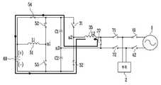
도 2는 도 1에 도시된 배터리 온도 제어 시스템의 실시예에 대한 회로도이다.2 is a circuit diagram of an embodiment of the battery temperature control system shown in FIG.
도 2를 참조하면, 본 발명에 실시예에 의한 배터리 온도 제어 시스템(200)은 도 1에 도시된 전력 저장 시스템의 구성요소들 중 배터리(60), 컨버터(50), DC 링크부(20), 인버터(30)로 구성되며, 도 2에서는 상기 배터리 온도 제어 시스템(200)과 연결되는 부하 연계기(70) 및 부하(2)와, 계통 연계기(40) 및 계통(1)이 도시되어 있다.Referring to FIG. 2, a battery
단, 도 2에서는 배터리(60)만 도시되어 있으나, 이는 설명의 편의를 위한 것으로 상기 배터리(60)에는 BMS가 포함되어 구현될 수 있다.In FIG. 2, only the
상기 컨버터(50)는 도 2에 도시된 바와 같이 제 1, 2스위치(52, 53) 및 하나의 컨버터 인덕터(L1)(51)로 구성되어 양방향 컨버팅 동작을 수행할 뿐 아니라, 상기 컨버터 인덕터(51)와 병렬로 연결된 제 3스위치(54)가 추가로 구성됨으로써, 상기 컨버터 인덕터(51)를 경유하지 않고 곧바로 배터리(60) 측으로의 충방전 전류 패스를 형성함을 특징으로 한다.The
상기 컨버터 인덕터(51)는 도시된 바와 같이 코일로 구현될 수 있으며, 이는 배터리(60)의 제 1단자(+)에 연결되는 제 1단자와, 상기 제 1스위치(52) 및 제 2스위치(53)의 사이의 노드(n1)와 연결되는 제 2단자를 포함한다.The
상기 제 1스위치(52)는 DC 링크부(20)를 구성하는 제 1캐패시터(C1)의 제 1단자와 컨버터 인덕터(51)의 제 2단자를 연결한다. 즉, 제 1스위치(52)의 제 1단자는 상기 제 1캐패시터(C1)의 제 1단자와 연결되고, 제 1스위치(52)의 제 2단자는 상기 컨버터 인덕터(51)의 제 2단자와 연결된다.The
또한, 상기 제 2스위치(53)는 컨버터 인덕터(51)의 제 2단자와, DC 링크부(20)를 구성하는 제 2캐패시터(C2)의 제 2단자 및 배터리(60)의 제 2단자(-)를 연결한다. 즉, 제 2스위치(53)의 제 1단자는 상기 컨버터 인덕터(51)의 제 2단자와 연결되고, 제 2스위치(53)의 제 2단자는 상기 제 2캐패시터(C2)의 제 2단자 및 배터리(60)의 제 2단자(-)와 연결된다.The
이와 같은 상기 제 1, 2스위치(52, 53)은 IGBT(Insulated gate bipolar transistor) 또는 MOSFET 스위치로 구현될 수 있으나, 이 외에도 스위칭 기능을 하는 스위칭 소자라면 모두 가능하다. 단, 상기 제 1, 2스위치(52, 53)가 MOSFET 스위치인 경우라면 상기 스위치(52, 53)의 제 1 단자는 소스 단자이고, 제 2 단자는 드레인 단자일 수 있다.The first and
이와 같은 구성을 갖는 컨버터(50)는 입력되는 전력의 전압을 승압하는 승압 컨버터 또는 강압할 수 있는 벅 컨버터로서 작용하는 양방향 컨버팅 동작을 수행할 수 있다.The
또한, 본 발명의 실시예에 의한 컨버터(50)는 기존의 일반적인 양방향 컨버팅 동작을 수행할 뿐 아니라, 상기 컨버터 인덕터(51)를 경유하지 않고 곧바로 배터리(60) 측으로의 충방전 전류 패스를 형성할 수 있도록 상기 컨버터 인덕터(51)와 병렬로 연결된 제 3스위치(54)가 추가로 구성됨을 특징으로 한다.In addition, the
즉, 상기 컨버터(50)에는 도시된 바와 같이 상기 배터리(60)의 제 1단자(+)와, 상기 DC 링크부에 구비된 제 1캐패시터(C1)의 제 1단자를 연결하는 제 3스위치(54)가 더 포함된다.That is, the
따라서, 상기 제 3스위치(54)가 턴 온되면 상기 컨버터 인덕터(51)를 경유하지 않고 곧바로 배터리(60) 측으로의 충방전 전류 패스가 형성되는 것이다.Therefore, when the
이 때, 상기 제 1 내지 3스위치(52, 53, 54)의 턴 온/오프의 제어는 앞서 도 1에 도시된 제어기(80)에 의해 수행된다.At this time, the control of turning on / off of the first to
다음으로 상기 인버터(30)는 도 2에 도시된 바와 같이 2개의 스위치들(31, 32)로 구성된 하프 브릿지(Half Bridge) 구조로 구현됨을 그 예로 설명한다.Next, as shown in FIG. 2, the
단, 본 발명의 실시예에 의한 인버터(30)는 이에 한정되지 않고, 풀 브릿지, 푸쉬-풀(Push-Pull) 구조로 인버터를 구성하거나, 4개 이상의 스위칭 소자들로 구성할 수 있음은 물론이다.However, the
보다 구체적으로 상기 인버터(30)는 도 2에 도시된 바와 같이 제 1, 2스위치(31, 32) 및 하나의 인버터 인덕터(L2)(35)로 구성되어 양방향 인버팅 동작을 수행할 뿐 아니라, 상기 인버터 인덕터(35)의 일측 단자(제 2단자)를 상기 DC 링크부(20)를 구성하는 제 1, 2캐패시터(C1, C2) 사이의 노드(n3)에 연결시키는 제 3스위치(37)가 추가로 구성됨으로써, 상기 인버터 인덕터(35)를 이용하여 배터리(60) 측으로 전달되는 충방전 전류를 발생시킴을 특징으로 한다. 즉, 제3 스위치(37)가 턴온 되면, 인버터 인덕터(35)를 이용하여 생성한 충방전 전류가 상기 배터리의 양극 또는 음극에 전달된다.More specifically, as shown in FIG. 2, the
이 때, 상기 인버터 인덕터(35)는 도시된 바와 같이 코일로 구현될 수 있으며, 이는 하프 브릿지 구조의 스위치들인 제 1, 2스위치(31, 32) 사이의 노드(n2)에 연결되는 제 1단자와, 상기 제 3스위치(37)의 제 1단자와 연결되는 제 2단자를 포함한다.In this case, the
즉, 상기 제 3스위치(37)이 턴 온되면 상기 인버터 인덕터(35)의 제 2단자는 DC 링크부(20)를 구성하는 제 1, 2캐패시터(C1, C2) 사이의 노드(n3)에 연결된다.That is, when the
또한, 상기 하프 브릿지 구조의 스위치들 중 상기 제 1스위치(31)는 DC 링크부(20)를 구성하는 제 1캐패시터(C1)의 제 1단자와 인버터 인덕터(L2)(35)의 제 1단자를 연결한다. 즉, 제 1스위치(31)의 제 1단자는 상기 제 1캐패시터(C1)의 제 1단자와 연결되고, 제 1스위치(31)의 제 2단자는 상기 인버터 인덕터(L2)(35)의 제 1단자와 연결된다.The
상기 제 2스위치(32)는 상기 인버터 인덕터(L2)(35)의 제 1단자와, DC 링크부(20)를 구성하는 제 2캐패시터(C2)의 제 2단자 및 배터리(60)의 제 2단자(-)를 연결한다. 즉, 제 2스위치(32)의 제 1단자는 상기 인버터 인덕터(L2)(35)의 제 1단자와 연결되고, 제 2스위치(32)의 제 2단자는 상기 제 2캐패시터(C2)의 제 2단자 및 배터리(60)의 제 2단자(-)와 연결된다.The
이와 같은 상기 제 1, 2스위치(31, 32)은 IGBT(Insulated gate bipolar transistor) 또는 MOSFET 스위치로 구현될 수 있으나, 이 외에도 스위칭 기능을 하는 스위칭 소자라면 모두 가능하다. 단, 상기 제 1, 2스위치(31, 32)가 MOSFET 스위치인 경우라면 상기 스위치들의 제 1 단자는 소스 단자이고, 제 2 단자는 드레인 단자일 수 있다.The first and
이와 같은 구성을 갖는 인버터(50)는 직류 전압을 교류 전압으로 변환하거나, 교류 전압을 정류하여 직류 전압을 변환하는 양방향 인버팅 동작을 수행할 수 있다.The
또한, 본 발명의 실시예에 의한 인버터(30)는 기존의 일반적인 양방향 인버팅 동작을 수행할 뿐 아니라, 상기 인버터 인덕터(35)를 이용하여 배터리 측으로 전달되는 충방전 전류를 발생시키기 위해 상기 인버터 인덕터(35)의 제 2단자를 상기 DC 링크부(20)를 구성하는 제 1, 2캐패시터(C1, C2) 사이의 노드(n3)에 연결시키는 제 3스위치(37)가 추가로 구성됨을 특징으로 한다.In addition, the
즉, 도 2에 도시된 실시예의 경우 상기 제 3스위치(37)는 상기 인버터 인덕터(35)의 제 2단자와 DC 링크부(20)를 구성하는 제 1, 2캐패시터(C1, C2) 사이의 노드(n3)를 연결하도록 구성된다.2, the
따라서, 상기 제 3스위치(37)가 턴 온되면 상기 인버터 인덕터(35)에서 발생된 전류가 부하(2) 또는 계통(1)이 아닌 배터리(60) 측으로의 전달될 수 있게 된다.Therefore, when the
단, 이를 위해서는 상기 부하 연계기(70)에 구비된 스위치들(71, 72) 및 계통 연계기(40)에 구비된 스위치들(41, 42)이 모두 턴 오프되어 상기 인버터(50)에 의해 변환된 전압이 상기 부하(2) 또는 계통(1)으로 전달되지 않도록 먼저 제어되어야 한다.In order to do this, however, the
이 때, 상기 인버터(30)의 제 1 내지 3스위치(31, 32, 37) 및 부하 연계기(70), 계통 연계기(40)에 구비된 스위치들에 대한 턴 온/오프의 제어는 앞서 도 1에 도시된 제어기(80)에 의해 수행된다.At this time, the control of the turn-on / off of the switches provided to the first to
이와 같은 본 발명의 실시예에 의한 배터리 온도 제어 시스템의 동작은, 상기 전력 저장 시스템(100)의 동작 중 배터리(60)의 저온 상태가 일정기간 유지됨이 제어기(80)에 의해 감지된 경우에 대응되는 동작이다.The operation of the battery temperature control system according to the embodiment of the present invention is performed when the
즉, 제어기(80)는 배터리(60)와 연결된 BMS를 통해 주기적으로 배터리의 정보를 수신하므로, 배터리(60)가 소정 기간 저온 상태가 유지되는 것을 감지할 수 있다.That is, the
상기 제어기(80)에 의해 배터리(60)의 저온 상태가 감지되면, 이후 상기 제어기(80)는 상기 배터리(60)의 온도를 상승시키기 위해 도 2에 도시된 배터리 온도 제어 시스템(200)의 동작을 제어하며, 이 경우 상기 전력 저장 시스템(100)의 기본적인 동작은 상기 배터리(60)가 정상 온도를 회복할 때까지 보류된다.When the low temperature state of the
상기 배터리 온도를 제어하는 기간 동안 상기 제어기(80)는 계통(1) 및 부하(2)와의 연결을 끊고 전력 저장 시스템(100)의 출력단측 인버터(30)의 인덕터(35)를 이용하여 상기 배터리(60) 측에 충방전 전류를 발생시킴을 통해 배터리의 온도를 상승시키는 동작을 수행하게 된다.The
도 1 및 도 2를 참조하면, 상기 제어기(80)가 배터리(60)에 구비된 BMS를 통해 배터리(60)의 저온 상태를 감지할 경우 상기 제어기(80)는 부하 연계기(70)의 스위치들(71, 72) 및 계통 연계기(40)의 스위치들(41, 42)을 턴 오프하여, 상기 전력 저장 시스템(100)과 상기 부하(3) 및 계통(1)과의 연계를 차단한다.1 and 2, when the
그리고, 인버터(30)에 포함된 제 3스위치(37)를 턴 온하여 상기 인버터(30)에 구비된 인버터 인덕터(35)의 제 2단자를 DC 링크부(20)를 구성하는 제 1, 2캐패시터(C1, C2) 사이의 노드(n3)에 연결시킨다.The
또한, 컨버터(50)에 포함된 제 3스위치(54)를 턴 온하여 상기 배터리(60)가 컨버터(50)의 인덕터(51)를 경유하지 않고 상기 인버터(30)와 직접 연결될 수 있도록 전류 패스가 형성된다.The
이후 상기 인버터(30)에 구비된 하프 브릿지 구조로 구현되는 2개의 스위치들을 교변 동작하여 상기 배터리의 충 방전 동작을 반복 수행하도록 한다.
Then, the two switches implemented in the half bridge structure included in the
도 3a 및 도 3b는 본 발명의 실시예에 의한 배터리 온도 제어 시스템 동작을 설명하는 도면이다.FIGS. 3A and 3B illustrate operation of a battery temperature control system according to an embodiment of the present invention.
도 3에 도시된 실시예는 상기 제어기(80)가 상기 인버터(30)에 포함된 스위치들 중 상기 제 1스위치(31)를 먼저 턴 온하고, 제 2스위치(32)를 턴 오프시키는 실시예를 나타낸다.The embodiment shown in FIG. 3 is similar to the embodiment in which the
도 3a를 참조하면, 도시된 바와 같이 상기 제 1스위치(31)를 턴 온하고, 제 2스위치(32)를 턴 오프하면, 상기 배터리(60)의 제 1단자(+)에서부터 컨버터(50)의 제 3스위치(54)와, DC 링크부(20)에 구비된 제 1캐패시터(C1)의 제 1단자와, 인버터(30)의 제 1스위치(31)와, 인버터 인덕터(35) 및 제 3스위치(37), DC 링크부의 제 2캐패시터(C2)를 거쳐 배터리(60)의 제 2단자(-)까지의 방전 패스가 형성된다.3A, when the
즉, 상기 도 3a에 의할 경우 상기 배터리(60)에는 상기 방전 패스를 통해 방전 전류가 흐르게 된다.That is, in the case of FIG. 3A, a discharge current flows through the discharge path to the
또한, 도 3b를 참조하면, 이는 상기 제어기(80)가 상기 인버터(30)에 포함된 스위치들 중 제 2스위치(32)를 턴 온하고, 제 1스위치(31)를 턴 오프한 것을 나타낸다.3B, this indicates that the
이 경우 상기 도 3a의 방전 패스와 반대의 방향을 갖는 충전 패스가 형성되고, 이를 통해 상기 인버터(30)의 인덕터(35)에 저장된 전력이 상기 배터리로 전달되어 상기 배터리(60)가 충전될 수 있게 된다.3A, the electric power stored in the
즉, 상기 도 3b에 의할 경우 상기 배터리(60)에는 상기 충전 패스를 통해 충전 전류가 흐르게 된다.That is, in the case of FIG. 3B, the charging current flows through the charging path to the
상기 충전 패스는 도 3b에 도시된 바와 같이 배터리(60)의 제 2단자(-)에서부터 인버터(30)의 제 2스위치(32) 및 인버터 인턱터(35), 제 3스위치(37) 및 DC 링크부(20)에 구비된 제 1캐패시터(C1)와, 컨버터(50)의 제 3스위치(54)를 거쳐 배터리(60)의 제 1단자(+)까지의 경로가 된다.
The charging path is switched from the second terminal (-) of the
도 4a 및 도 4b는 본 발명의 다른 실시예에 의한 배터리 온도 제어 시스템 동작을 설명하는 도면이다.4A and 4B are diagrams illustrating operation of a battery temperature control system according to another embodiment of the present invention.
도 4에 도시된 실시예는 상기 제어기(80)가 상기 인버터(30)에 포함된 스위치들 중 상기 제 2스위치(32)를 먼저 턴 온하고, 제 1스위치(31)를 턴 오프시키는 실시예를 나타낸다.The embodiment shown in FIG. 4 is an embodiment in which the
도 4a를 참조하면, 도시된 바와 같이 상기 제 2스위치(32)를 턴 온하고, 제 1스위치(31)를 턴 오프하면, 상기 배터리(60)의 제 1단자(+)에서부터 컨버터(50)의 제 3스위치(54)와, DC 링크부(20)에 구비된 제 1캐패시터(C1)와, 인버터(30)의 제 3스위치(37)와, 인버터 인덕터(35) 및 제 2스위치(32)를 거쳐 배터리(60)의 제 2단자(-)까지의 방전 패스가 형성된다.Referring to FIG. 4A, when the
즉, 상기 도 4a에 의할 경우 상기 배터리(60)에는 상기 방전 패스를 통해 방전 전류가 흐르게 된다.That is, according to FIG. 4A, a discharge current flows through the discharge path to the
또한, 도 4b를 참조하면, 이는 상기 제어기(80)가 상기 인버터(30)에 포함된 스위치들 중 제 1스위치(31)를 턴 온하고, 제 2스위치(32)를 턴 오프한 것을 나타낸다.4B, this indicates that the
이 경우 상기 도 4a의 방전 패스와 반대의 방향을 갖는 충전 패스가 형성되고, 이를 통해 상기 인버터(30)의 인덕터(35)에 저장된 전력이 상기 배터리로 전달되어 상기 배터리(60)가 충전될 수 있게 된다.In this case, a charging path having a direction opposite to that of the discharging path of FIG. 4A is formed, whereby the electric power stored in the
즉, 상기 도 4b에 의할 경우 상기 배터리(60)에는 상기 충전 패스를 통해 충전 전류가 흐르게 된다.4B, the charging current flows through the charging path to the
상기 충전 패스는 도 4b에 도시된 바와 같이 배터리(60)의 제 2단자(-)에서부터 DC 링크부(20)에 구비된 제 2캐패시터(C2)와, 인버터(30)의 제 3스위치(37) 및 인버터 인턱터(35), 제 1스위치(31) 및 컨버터(50)의 제 3스위치(54)를 거쳐 배터리(60)의 제 1단자(+)까지의 경로가 된다.
The charging path includes a second capacitor C2 provided from the second terminal (-) of the
앞서 언급한 바와 같이 본 발명의 실시예에 의한 배터리 온도 제어 시스템은 상기 인버터(30)에 구비된 하프 브릿지 구조로 구현되는 2개의 스위치들을 교변 동작하여 상기 배터리의 충 방전 동작을 반복 수행함을 특징으로 하는 것으로서, 도 3 및 도 4의 동작을 나누어 설명하였으나, 도 3a 내지 도 4b의 단계가 순차적으로 반복 수행될 수 있다.As described above, in the battery temperature control system according to the embodiment of the present invention, the charge / discharge operation of the battery is repeated by interchangeably operating the two switches implemented in the half bridge structure included in the
즉, 상기 제어기(80)는 도 3a 내지 도 4b의 동작을 반복하여 수행함을 통해 배터리(60)에는 충전 및 방전전류가 반복하여 흐르게 되고, 이 전류로 인해 배터리(60)의 온도는 상승하게 된다.That is, the
이후 배터리(60)의 온도가 정상 온도 범위에 도달하면, 상기 제어기(80)는 본 발명의 실시예에 의한 배터리 온도 제어 시스템의 동작을 종료하고, 전력 저장 시스템(100)의 기본적인 동작을 수행한다.Thereafter, when the temperature of the
즉, 부하 연계기(70)의 스위치들(71, 72) 및 계통 연계기(40)의 스위치들(41, 42)을 턴 온하여 상기 전력 저장 시스템(100)을 상기 부하(3) 및 계통(1)과 연결시킨다.That is, the
또한, 상기 인버터(30)에 포함된 제 3스위치(37)는 턴 오프하여 인버터(30)가 기본적인 양방향 인버팅 동작만을 수행하고, 이와 마찬가지로 상기 컨버터(50)에 포함된 제 3스위치(54) 역시 턴 오프하여 컨버터(50)가 기본적인 양방향 컨버팅 동작만을 수행한다. 즉, 상기 배터리 온도 제어 시스템 동작 시 형성된 충방전 전류 패스가 차단된다.
The
이상 설명한 내용을 통해 당업자라면 본 발명의 기술사상을 일탈하지 아니하는 범위에서 다양한 변경 및 수정이 가능함을 알 수 있을 것이다. 따라서, 본 발명의 기술적 범위는 명세서의 상세한 설명에 기재된 내용으로 한정되는 것이 아니라 특허 청구의 범위에 의하여 정하여져야만 한다.It will be apparent to those skilled in the art that various modifications and variations can be made in the present invention without departing from the spirit or scope of the invention. Therefore, the technical scope of the present invention should not be limited to the contents described in the detailed description of the specification, but should be determined by the claims.
100: 전력 저장 시스템20: DC 링크부
30: 인버터50: 컨버터
60: 배터리80: 제어기
200: 배터리 온도 제어 시스템100: power storage system 20: DC link part
30: inverter 50: converter
60: Battery 80: Controller
200: Battery temperature control system
Claims (10)
Translated fromKorean복수의 스위치 및 하나의 컨버터 인덕터로 구성되어 상기 배터리의 전압을 승압 또는 감압하는 컨버터와;
상기 컨버터의 출력 전압을 안정화시키는 제 1, 2캐패시터가 직렬로 연결된 DC 링크부와;
복수의 스위치 및 하나의 인버터 인덕터로 구성되어 입력되는 전압을 변환(inverting)하는 인버터;가 포함되며,
상기 인버터는 상기 인버터 인덕터에서 생성된 전류를 상기 배터리 측으로 전달되도록 상기 인버터 인덕터의 일측 단자를 상기 DC 링크부를 구성하는 제 1, 2캐패시터 사이의 노드에 연결하는 인버터의 제3 스위치가 더 포함되고,
상기 인버터의 제3 스위치는 턴 온되면, 상기 인버터 인덕터를 이용하여 생성한 전류가 상기 배터리의 양극 또는 음극에 전달되고,
상기 컨버터는, 상기 배터리의 제 1단자에 연결되는 상기 컨버터 인덕터와; 상기 DC 링크부에 구비된 캐패시터의 제 1단자와 상기 컨버터 인덕터의 제 2단자 사이에 연결되는 제1 스위치와; 상기 컨버터 인덕터의 제 2단자와 상기 배터리의 제 2단자 사이에 연결되는 제 2스위치가 포함되는 것을 특징으로 하는 배터리 온도 제어 시스템.A battery included in the power storage system;
A converter configured by a plurality of switches and one converter inductor to step up or down the voltage of the battery;
A DC link unit having first and second capacitors serially connected to stabilize the output voltage of the converter;
An inverter configured by a plurality of switches and one inverter inductor and inverting an input voltage,
The inverter further includes a third switch of an inverter which connects one terminal of the inverter inductor to a node between the first and second capacitors constituting the DC link portion so that a current generated in the inverter inductor is transmitted to the battery side,
When the third switch of the inverter is turned on, the current generated by the inverter inductor is transmitted to the anode or the cathode of the battery,
The converter comprising: a converter inductor coupled to a first terminal of the battery; A first switch connected between a first terminal of the capacitor included in the DC link unit and a second terminal of the converter inductor; And a second switch connected between a second terminal of the converter inductor and a second terminal of the battery.
상기 배터리의 제 1단자와 상기 DC 링크부에 구비된 제 1캐패시터의 제 1단자 사이에 연결되는 제 3스위치가 더 포함됨을 특징으로 하는 배터리 온도 제어 시스템.The method according to claim 1,
Further comprising a third switch connected between a first terminal of the battery and a first terminal of a first capacitor provided in the DC link unit.
상기 인버터는 입력되는 전압을 변환하기 위해 구비되는 복수의 스위치들은 하프 브릿지(Half Bridge) 구조로 구현됨을 특징으로 하는 배터리 온도 제어 시스템.The method according to claim 1,
Wherein the plurality of switches included in the inverter for converting an input voltage are implemented as a half bridge structure.
상기 하프 브릿지 구조의 스위치들은,
상기 DC 링크부에 구비된 제 1캐패시터의 제 1단자와 상기 인버터 인덕터의 제 1단자 사이에 연결되는 인버터의 제 1스위치와;
상기 인버터 인덕터의 제 1단자와 상기 배터리의 제 2단자 사이에 연결되는 인버터의 제 2스위치로 구성됨을 특징으로 하는 배터리 온도 제어 시스템.5. The method of claim 4,
The switches of the half-
A first switch of an inverter connected between a first terminal of a first capacitor provided in the DC link part and a first terminal of the inverter inductor;
And a second switch of an inverter connected between a first terminal of the inverter inductor and a second terminal of the battery.
상기 인버터 인덕터는 상기 인버터의 제 1스위치 및 상기 인버터의 제 2스위치 사이의 노드와, 전력 저장 시스템과 부하 간의 연계를 제어하는 부하 연계기의 제 1스위치 사이에 연결됨을 특징으로 하는 배터리 온도 제어 시스템.6. The method of claim 5,
Wherein the inverter inductor is connected between a node between the first switch of the inverter and the second switch of the inverter and a first switch of the load interconnector that controls the connection between the power storage system and the load.
상기 인버터의 제3 스위치는 상기 인버터 인덕터의 제 2단자와 DC 링크부를 구성하는 제 1, 2캐패시터 사이의 노드에 연결되는 것을 특징으로 하는 배터리 온도 제어 시스템.6. The method of claim 5,
And a third switch of the inverter is connected to a node between the second terminal of the inverter inductor and the first and second capacitors constituting the DC link portion.
상기 배터리의 저온 상태가 일정기간 유지됨이 감지되는 단계와;
상기 배터의 저온 상태가 감지되면, 상기 전력 저장 시스템과 연계된 계통 및 부하의 연결이 차단되는 단계와;
상기 전력 저장 시스템 내의 인버터에 구비된 인버터 인덕터에서 생성된 전류가 상기 배터리 측으로 전달되는 충방전 전류 패스가 형성되는 단계와;
상기 인버터에 구비된 복수개의 스위치들이 교변 동작하여 상기 충방전 전류 패스를 통해 상기 배터리의 충 방전 동작이 반복 수행되는 단계;가 포함되고,
상기 충방전 전류 패스는 상기 전력 저장 시스템 내의 컨버터에 구비된 컨버터 인덕터를 경유하지 않고 곧바로 상기 배터리로 흐르는 전류 패스인 것을 특징으로 하는 배터리 온도 제어 방법.A method for controlling a temperature of a battery included in a power storage system,
Detecting that the low temperature state of the battery is maintained for a predetermined period;
When the low-temperature state of the batter is sensed, disconnecting the grid and the load associated with the power storage system;
A charge / discharge current path through which a current generated in an inverter inductor provided in an inverter in the power storage system is transmitted to the battery is formed;
And a plurality of switches provided in the inverter interchangeably operate so that charging and discharging operations of the battery are repeatedly performed through the charging and discharging current path,
Wherein the charge / discharge current path is a current path that flows directly to the battery without passing through a converter inductor provided in a converter in the power storage system.
상기 배터리의 온도가 정상 온도 범위에 도달한 이후 상기 전력 저장 시스템이 상기 부하 및 계통과 연결되고 상기 형성된 충방전 전류 패스가 차단되는 단계가 더 포함됨을 특징으로 하는 배터리 온도 제어 방법.9. The method of claim 8,
Further comprising: after the temperature of the battery reaches a normal temperature range, the power storage system is connected to the load and the system and the formed charge / discharge current path is blocked.
상기 인버터에 구비된 복수개의 스위치들은 하프 브릿지(Half Bridge) 구조로 구현됨을 특징으로 하는 배터리 온도 제어 방법.9. The method of claim 8,
Wherein the plurality of switches provided in the inverter are implemented as a half bridge structure.
Priority Applications (2)
| Application Number | Priority Date | Filing Date | Title |
|---|---|---|---|
| KR1020130005046AKR101698771B1 (en) | 2013-01-16 | 2013-01-16 | temperature controlling system of battery and controlling method thereof |
| US13/935,462US9356323B2 (en) | 2013-01-16 | 2013-07-03 | Temperature controlling system and method for battery |
Applications Claiming Priority (1)
| Application Number | Priority Date | Filing Date | Title |
|---|---|---|---|
| KR1020130005046AKR101698771B1 (en) | 2013-01-16 | 2013-01-16 | temperature controlling system of battery and controlling method thereof |
Publications (2)
| Publication Number | Publication Date |
|---|---|
| KR20140092978A KR20140092978A (en) | 2014-07-25 |
| KR101698771B1true KR101698771B1 (en) | 2017-01-23 |
Family
ID=51164649
Family Applications (1)
| Application Number | Title | Priority Date | Filing Date |
|---|---|---|---|
| KR1020130005046AActiveKR101698771B1 (en) | 2013-01-16 | 2013-01-16 | temperature controlling system of battery and controlling method thereof |
Country Status (2)
| Country | Link |
|---|---|
| US (1) | US9356323B2 (en) |
| KR (1) | KR101698771B1 (en) |
Families Citing this family (18)
| Publication number | Priority date | Publication date | Assignee | Title |
|---|---|---|---|---|
| CN105409088A (en)* | 2013-06-13 | 2016-03-16 | 上海火亮新能源科技有限公司 | Battery energy storage system and controlling method |
| EP2827467A3 (en)* | 2013-07-18 | 2015-04-22 | Solantro Semiconductor Corp. | Stabilized power generation |
| US10797490B2 (en)* | 2014-03-26 | 2020-10-06 | Intersil Americas LLC | Battery charge system with transition control that protects adapter components when transitioning from battery mode to adapter mode |
| DE102014211206B3 (en)* | 2014-06-12 | 2015-09-10 | Continental Automotive Gmbh | Device having a printed circuit board and an electronic circuit arranged thereon, which has an electrolytic capacitor whose operating temperature can be regulated by means of the electronic circuit |
| CN104167799B (en)* | 2014-08-29 | 2017-10-17 | 阳光电源股份有限公司 | A kind of charge-discharge system, method and photovoltaic generating system |
| EP3314714B1 (en) | 2015-06-29 | 2019-11-06 | ABB Schweiz AG | A multi-level power converter and a method for controlling a multi-level power converter |
| EP3317214B1 (en) | 2015-07-01 | 2020-02-19 | Otis Elevator Company | Lithium-ion battery charging system for a battery powered elevator system |
| GB2563679B (en)* | 2017-06-19 | 2022-07-06 | Tridonic Gmbh & Co Kg | Emergency converter output switching |
| WO2019097926A1 (en)* | 2017-11-16 | 2019-05-23 | 株式会社村田製作所 | Power storage module and power supply system |
| KR102375845B1 (en) | 2017-11-24 | 2022-03-17 | 주식회사 엘지에너지솔루션 | Battery and Method for controlling battery temperature |
| US10148124B1 (en)* | 2018-01-05 | 2018-12-04 | Channel Well Technology Co., Ltd. | Uninterrupted power bank capable of supplying high DC voltage during interruption of main supply and providing AC voltage as normal supply of the main supply |
| KR101840619B1 (en)* | 2018-01-11 | 2018-03-20 | (주)엠에스엔코리아 | Battery Experiment Apparatus |
| US11594883B2 (en)* | 2018-01-23 | 2023-02-28 | Tdk Corporation | Direct current power supplying system |
| DE102018207797B3 (en)* | 2018-05-17 | 2019-11-14 | Volkswagen Aktiengesellschaft | Device for temperature conditioning of a battery, battery unit and method for temperature conditioning of a battery |
| WO2020072441A1 (en)* | 2018-10-02 | 2020-04-09 | Jabil Inc. | Apparatus, system and method for a self-heating battery circuit |
| KR102681823B1 (en)* | 2018-11-20 | 2024-07-03 | 주식회사 엘지에너지솔루션 | Apparatus and method for battery heating, and battery pack including the apparatus |
| CN112952882B (en)* | 2021-04-13 | 2024-04-12 | 阳光电源股份有限公司 | Energy storage conversion system, control method of energy storage conversion system, and computer-readable storage medium |
| CN115668588A (en)* | 2022-03-11 | 2023-01-31 | 宁德时代新能源科技股份有限公司 | Battery heating device, control method and circuit thereof, and power device |
Citations (2)
| Publication number | Priority date | Publication date | Assignee | Title |
|---|---|---|---|---|
| JP2011254673A (en) | 2010-06-04 | 2011-12-15 | Honda Motor Co Ltd | Battery heating apparatus for vehicle |
| JP2012070502A (en) | 2010-09-22 | 2012-04-05 | Toyota Motor Corp | Power control unit to be mounted on vehicle |
Family Cites Families (44)
| Publication number | Priority date | Publication date | Assignee | Title |
|---|---|---|---|---|
| US4016473A (en)* | 1975-11-06 | 1977-04-05 | Utah Research & Development Co., Inc. | DC powered capacitive pulse charge and pulse discharge battery charger |
| US5623195A (en)* | 1994-06-22 | 1997-04-22 | Lucent Technologies Inc. | Apparatus and method for controlling a charging voltage of a battery based on battery temperature |
| KR100263551B1 (en)* | 1996-10-12 | 2000-08-01 | 윤종용 | Secondary battery charging circuit |
| US6259229B1 (en)* | 1998-04-30 | 2001-07-10 | Daimlerchrysler Corporation | Circulating current battery heater |
| JP4081855B2 (en)* | 1998-05-14 | 2008-04-30 | 日産自動車株式会社 | Battery temperature riser |
| US6340879B1 (en)* | 1999-02-03 | 2002-01-22 | Nokia Mobile Phones Ltd. | Device for reactivating an electric battery |
| DE19904181A1 (en) | 1999-02-03 | 2000-08-10 | Nokia Mobile Phones Ltd | Device for reactivating an electric battery |
| JP4308408B2 (en)* | 2000-04-28 | 2009-08-05 | パナソニック株式会社 | Secondary battery input / output controller |
| US6271648B1 (en)* | 2000-09-27 | 2001-08-07 | Ford Global Tech., Inc. | Method of preconditioning a battery to improve cold temperature starting of a vehicle |
| JP2002125326A (en)* | 2000-10-12 | 2002-04-26 | Honda Motor Co Ltd | Battery charge control method |
| US7327122B2 (en)* | 2002-07-17 | 2008-02-05 | Mathews Associates, Inc. | Battery heating circuit |
| US7425816B2 (en)* | 2002-11-22 | 2008-09-16 | Milwaukee Electric Tool Corporation | Method and system for pulse charging of a lithium-based battery |
| US6850039B2 (en)* | 2003-05-02 | 2005-02-01 | O2Micro International Limited | Battery pack and a battery charging/discharging circuit incorporating the same |
| US7737658B2 (en)* | 2003-10-27 | 2010-06-15 | Sony Corporation | Battery packs having a charging mode and a discharging mode |
| CN100499251C (en)* | 2004-10-29 | 2009-06-10 | 日本电气株式会社 | Storage battery temperature control apparatus and storage battery temperature control method |
| JP5008863B2 (en)* | 2005-11-30 | 2012-08-22 | プライムアースEvエナジー株式会社 | Secondary battery control device, secondary battery deterioration determination method using secondary battery temperature estimation method |
| JP4535039B2 (en) | 2006-07-25 | 2010-09-01 | トヨタ自動車株式会社 | Power supply system, vehicle equipped with the same, power storage device temperature rise control method, and computer-readable recording medium storing a program for causing a computer to execute power storage device temperature rise control |
| US7557516B2 (en)* | 2007-03-21 | 2009-07-07 | System General Corp. | Resonant inverter |
| US8049460B2 (en)* | 2007-07-18 | 2011-11-01 | Tesla Motors, Inc. | Voltage dividing vehicle heater system and method |
| US8212412B1 (en)* | 2007-11-30 | 2012-07-03 | Northern Power Systems Utility Scale, Inc. | Energy storage connection system |
| EP2332246A1 (en)* | 2008-09-11 | 2011-06-15 | Eetrex Incorporated | Bi-directional inverter-charger |
| JP4811503B2 (en)* | 2009-07-08 | 2011-11-09 | トヨタ自動車株式会社 | Secondary battery temperature increase control device, vehicle equipped with the same, and secondary battery temperature increase control method |
| JP4840481B2 (en)* | 2009-07-08 | 2011-12-21 | トヨタ自動車株式会社 | Secondary battery temperature increase control device, vehicle equipped with the same, and secondary battery temperature increase control method |
| WO2011015974A1 (en)* | 2009-08-02 | 2011-02-10 | Steve Carkner | Battery self heating system |
| US8452490B2 (en)* | 2009-12-14 | 2013-05-28 | Control Solutions LLC | Electronic circuit for charging and heating a battery |
| EP2339715B1 (en)* | 2009-12-22 | 2012-08-08 | CTEK Sweden AB | A battery charging system, a battery operated system and a method for state controlled charging |
| KR101156535B1 (en) | 2010-01-18 | 2012-06-21 | 삼성에스디아이 주식회사 | Apparatus for energy storage, operation method thereof and energy storage system |
| KR101166020B1 (en)* | 2010-05-31 | 2012-07-19 | 삼성에스디아이 주식회사 | Contactless charging system and energy storage system including the same |
| KR101106413B1 (en)* | 2010-06-14 | 2012-01-17 | 삼성에스디아이 주식회사 | Inverter of energy storage system |
| KR101116428B1 (en) | 2010-07-14 | 2012-03-05 | 삼성에스디아이 주식회사 | Energy Storage System |
| US8941358B2 (en)* | 2010-07-30 | 2015-01-27 | Byd Company Limited | Heating circuits and methods based on battery discharging and charging using resonance components in series and freewheeling circuit components |
| CN201936967U (en)* | 2010-07-30 | 2011-08-17 | 比亚迪股份有限公司 | Heating circuit of battery |
| US8994332B2 (en)* | 2010-07-30 | 2015-03-31 | Byd Company Limited | Battery heating circuits and methods using voltage inversion based on predetermined conditions |
| US8947049B2 (en)* | 2010-07-30 | 2015-02-03 | Byd Company Limited | Battery heating circuits and methods using voltage inversion and freewheeling circuit components |
| US8344697B2 (en)* | 2010-08-02 | 2013-01-01 | GM Global Technlogy Operations LLC | Method for optimized design and operation of battery cooling system in electric vehicles |
| CN102545317B (en)* | 2010-12-20 | 2015-08-05 | 株式会社电装 | The system risen for causing battery temperature |
| US8890467B2 (en)* | 2011-03-28 | 2014-11-18 | Continental Automotive Systems, Inc. | System for controlling battery conditions |
| JP5998454B2 (en)* | 2011-11-07 | 2016-09-28 | ソニー株式会社 | Control device, control method, and control system |
| US20130271069A1 (en)* | 2012-03-21 | 2013-10-17 | Mojo Mobility, Inc. | Systems and methods for wireless power transfer |
| US9209500B2 (en) | 2012-09-24 | 2015-12-08 | Samsung Sdi Co., Ltd. | Temperature controlling system and method of battery |
| KR20140097628A (en)* | 2013-01-28 | 2014-08-07 | 삼성에스디아이 주식회사 | temperature controlling system of battery and controlling method thereof |
| KR101688485B1 (en)* | 2013-02-28 | 2016-12-21 | 삼성에스디아이 주식회사 | Energy storage apparatus |
| KR20140115501A (en)* | 2013-03-20 | 2014-10-01 | 삼성에스디아이 주식회사 | Power conversion device having battery heating function |
| US8907631B1 (en)* | 2013-07-31 | 2014-12-09 | Qnovo Inc. | Adaptive charging technique and circuitry for a battery/cell using multiple charge circuits and temperature data |
- 2013
- 2013-01-16KRKR1020130005046Apatent/KR101698771B1/enactiveActive
- 2013-07-03USUS13/935,462patent/US9356323B2/enactiveActive
Patent Citations (2)
| Publication number | Priority date | Publication date | Assignee | Title |
|---|---|---|---|---|
| JP2011254673A (en) | 2010-06-04 | 2011-12-15 | Honda Motor Co Ltd | Battery heating apparatus for vehicle |
| JP2012070502A (en) | 2010-09-22 | 2012-04-05 | Toyota Motor Corp | Power control unit to be mounted on vehicle |
Also Published As
| Publication number | Publication date |
|---|---|
| KR20140092978A (en) | 2014-07-25 |
| US9356323B2 (en) | 2016-05-31 |
| US20140197778A1 (en) | 2014-07-17 |
Similar Documents
| Publication | Publication Date | Title |
|---|---|---|
| KR101698771B1 (en) | temperature controlling system of battery and controlling method thereof | |
| KR101678536B1 (en) | temperature controlling system of battery and energy storage system using the same and controlling method thereof | |
| KR20140097628A (en) | temperature controlling system of battery and controlling method thereof | |
| KR101146670B1 (en) | Energy management system and method for controlling thereof | |
| US9293923B2 (en) | Energy storage system and controlling method of the same | |
| KR101084214B1 (en) | Grid-connected power storage system and control method of power storage system | |
| US8552590B2 (en) | Energy management system and grid-connected energy storage system including the energy management system | |
| KR101156533B1 (en) | Energy storage system and method for controlling thereof | |
| KR101084215B1 (en) | Energy storage system and its control method | |
| KR101094002B1 (en) | Power converter | |
| US20130088900A1 (en) | Energy storage system and controlling method of the same | |
| JP2011109901A5 (en) | ||
| KR101688485B1 (en) | Energy storage apparatus | |
| US20110304212A1 (en) | Renewable energy storage system | |
| KR20140115501A (en) | Power conversion device having battery heating function | |
| US20140085935A1 (en) | Power conversion device |
Legal Events
| Date | Code | Title | Description |
|---|---|---|---|
| PA0109 | Patent application | Patent event code:PA01091R01D Comment text:Patent Application Patent event date:20130116 | |
| PG1501 | Laying open of application | ||
| A201 | Request for examination | ||
| PA0201 | Request for examination | Patent event code:PA02012R01D Patent event date:20150226 Comment text:Request for Examination of Application Patent event code:PA02011R01I Patent event date:20130116 Comment text:Patent Application | |
| E902 | Notification of reason for refusal | ||
| PE0902 | Notice of grounds for rejection | Comment text:Notification of reason for refusal Patent event date:20160421 Patent event code:PE09021S01D | |
| AMND | Amendment | ||
| E601 | Decision to refuse application | ||
| PE0601 | Decision on rejection of patent | Patent event date:20161020 Comment text:Decision to Refuse Application Patent event code:PE06012S01D Patent event date:20160421 Comment text:Notification of reason for refusal Patent event code:PE06011S01I | |
| X091 | Application refused [patent] | ||
| AMND | Amendment | ||
| PX0901 | Re-examination | Patent event code:PX09011S01I Patent event date:20161020 Comment text:Decision to Refuse Application Patent event code:PX09012R01I Patent event date:20160621 Comment text:Amendment to Specification, etc. | |
| PX0701 | Decision of registration after re-examination | Patent event date:20161220 Comment text:Decision to Grant Registration Patent event code:PX07013S01D Patent event date:20161121 Comment text:Amendment to Specification, etc. Patent event code:PX07012R01I Patent event date:20161020 Comment text:Decision to Refuse Application Patent event code:PX07011S01I Patent event date:20160621 Comment text:Amendment to Specification, etc. Patent event code:PX07012R01I | |
| X701 | Decision to grant (after re-examination) | ||
| GRNT | Written decision to grant | ||
| PR0701 | Registration of establishment | Comment text:Registration of Establishment Patent event date:20170117 Patent event code:PR07011E01D | |
| PR1002 | Payment of registration fee | Payment date:20170118 End annual number:3 Start annual number:1 | |
| PG1601 | Publication of registration | ||
| FPAY | Annual fee payment | Payment date:20200103 Year of fee payment:4 | |
| PR1001 | Payment of annual fee | Payment date:20200103 Start annual number:4 End annual number:4 | |
| PR1001 | Payment of annual fee | Payment date:20210106 Start annual number:5 End annual number:5 | |
| PR1001 | Payment of annual fee | Payment date:20230103 Start annual number:7 End annual number:7 | |
| PR1001 | Payment of annual fee | Payment date:20231226 Start annual number:8 End annual number:8 |