KR101698353B1 - Cartridge Unit and Drug Infusion Device Having the Same - Google Patents
Cartridge Unit and Drug Infusion Device Having the SameDownload PDFInfo
- Publication number
- KR101698353B1 KR101698353B1KR1020150151185AKR20150151185AKR101698353B1KR 101698353 B1KR101698353 B1KR 101698353B1KR 1020150151185 AKR1020150151185 AKR 1020150151185AKR 20150151185 AKR20150151185 AKR 20150151185AKR 101698353 B1KR101698353 B1KR 101698353B1
- Authority
- KR
- South Korea
- Prior art keywords
- drug
- opening
- connector
- flow path
- discharge port
- Prior art date
- Legal status (The legal status is an assumption and is not a legal conclusion. Google has not performed a legal analysis and makes no representation as to the accuracy of the status listed.)
- Active
Links
- 239000003814drugSubstances0.000titleclaimsabstractdescription123
- 229940079593drugDrugs0.000titleclaimsabstractdescription121
- 238000001802infusionMethods0.000titleabstractdescription3
- 238000004891communicationMethods0.000claimsabstractdescription40
- 238000003780insertionMethods0.000claimsabstractdescription30
- 230000037431insertionEffects0.000claimsabstractdescription30
- 238000000034methodMethods0.000claimsdescription19
- 230000002265preventionEffects0.000claimsdescription3
- 230000005540biological transmissionEffects0.000claimsdescription2
- 238000003384imaging methodMethods0.000claimsdescription2
- 238000009751slip formingMethods0.000claims2
- 230000002093peripheral effectEffects0.000claims1
- 239000000243solutionSubstances0.000description55
- 238000007599dischargingMethods0.000description7
- 238000002347injectionMethods0.000description7
- 239000007924injectionSubstances0.000description7
- 238000005259measurementMethods0.000description6
- 230000004308accommodationEffects0.000description5
- 230000000694effectsEffects0.000description3
- 230000003287optical effectEffects0.000description2
- 239000013307optical fiberSubstances0.000description2
- 210000003491skinAnatomy0.000description2
- 230000000903blocking effectEffects0.000description1
- 210000004204blood vesselAnatomy0.000description1
- 238000010276constructionMethods0.000description1
- 239000000356contaminantSubstances0.000description1
- 238000011109contaminationMethods0.000description1
- 230000008878couplingEffects0.000description1
- 238000010168coupling processMethods0.000description1
- 238000005859coupling reactionMethods0.000description1
- 210000004207dermisAnatomy0.000description1
- 201000010099diseaseDiseases0.000description1
- 208000037265diseases, disorders, signs and symptomsDiseases0.000description1
- 210000002615epidermisAnatomy0.000description1
- 239000007927intramuscular injectionSubstances0.000description1
- 238000010255intramuscular injectionMethods0.000description1
- 238000010253intravenous injectionMethods0.000description1
- 210000003205muscleAnatomy0.000description1
- 230000001151other effectEffects0.000description1
- 206010033675panniculitisDiseases0.000description1
- 239000007929subcutaneous injectionSubstances0.000description1
- 238000010254subcutaneous injectionMethods0.000description1
- 210000004304subcutaneous tissueAnatomy0.000description1
- 210000001519tissueAnatomy0.000description1
- 210000003462veinAnatomy0.000description1
Images


Classifications
- A—HUMAN NECESSITIES
- A61—MEDICAL OR VETERINARY SCIENCE; HYGIENE
- A61M—DEVICES FOR INTRODUCING MEDIA INTO, OR ONTO, THE BODY; DEVICES FOR TRANSDUCING BODY MEDIA OR FOR TAKING MEDIA FROM THE BODY; DEVICES FOR PRODUCING OR ENDING SLEEP OR STUPOR
- A61M5/00—Devices for bringing media into the body in a subcutaneous, intra-vascular or intramuscular way; Accessories therefor, e.g. filling or cleaning devices, arm-rests
- A61M5/178—Syringes
- A61M5/31—Details
- A61M5/315—Pistons; Piston-rods; Guiding, blocking or restricting the movement of the rod or piston; Appliances on the rod for facilitating dosing ; Dosing mechanisms
- A61M5/31565—Administration mechanisms, i.e. constructional features, modes of administering a dose
- A61M5/31576—Constructional features or modes of drive mechanisms for piston rods
- A61M5/31578—Constructional features or modes of drive mechanisms for piston rods based on axial translation, i.e. components directly operatively associated and axially moved with plunger rod
- A61M5/3158—Constructional features or modes of drive mechanisms for piston rods based on axial translation, i.e. components directly operatively associated and axially moved with plunger rod performed by axially moving actuator operated by user, e.g. an injection button
- A—HUMAN NECESSITIES
- A61—MEDICAL OR VETERINARY SCIENCE; HYGIENE
- A61M—DEVICES FOR INTRODUCING MEDIA INTO, OR ONTO, THE BODY; DEVICES FOR TRANSDUCING BODY MEDIA OR FOR TAKING MEDIA FROM THE BODY; DEVICES FOR PRODUCING OR ENDING SLEEP OR STUPOR
- A61M39/00—Tubes, tube connectors, tube couplings, valves, access sites or the like, specially adapted for medical use
- A61M39/22—Valves or arrangement of valves
- A—HUMAN NECESSITIES
- A61—MEDICAL OR VETERINARY SCIENCE; HYGIENE
- A61M—DEVICES FOR INTRODUCING MEDIA INTO, OR ONTO, THE BODY; DEVICES FOR TRANSDUCING BODY MEDIA OR FOR TAKING MEDIA FROM THE BODY; DEVICES FOR PRODUCING OR ENDING SLEEP OR STUPOR
- A61M5/00—Devices for bringing media into the body in a subcutaneous, intra-vascular or intramuscular way; Accessories therefor, e.g. filling or cleaning devices, arm-rests
- A61M5/178—Syringes
- A61M5/31—Details
- A61M5/315—Pistons; Piston-rods; Guiding, blocking or restricting the movement of the rod or piston; Appliances on the rod for facilitating dosing ; Dosing mechanisms
- A61M5/31565—Administration mechanisms, i.e. constructional features, modes of administering a dose
- A61M5/3159—Dose expelling manners
- A61M5/31593—Multi-dose, i.e. individually set dose repeatedly administered from the same medicament reservoir
- A61M5/31595—Pre-defined multi-dose administration by repeated overcoming of means blocking the free advancing movement of piston rod, e.g. by tearing or de-blocking
- A—HUMAN NECESSITIES
- A61—MEDICAL OR VETERINARY SCIENCE; HYGIENE
- A61M—DEVICES FOR INTRODUCING MEDIA INTO, OR ONTO, THE BODY; DEVICES FOR TRANSDUCING BODY MEDIA OR FOR TAKING MEDIA FROM THE BODY; DEVICES FOR PRODUCING OR ENDING SLEEP OR STUPOR
- A61M5/00—Devices for bringing media into the body in a subcutaneous, intra-vascular or intramuscular way; Accessories therefor, e.g. filling or cleaning devices, arm-rests
- A61M5/42—Devices for bringing media into the body in a subcutaneous, intra-vascular or intramuscular way; Accessories therefor, e.g. filling or cleaning devices, arm-rests having means for desensitising skin, for protruding skin to facilitate piercing, or for locating point where body is to be pierced
- A61M5/427—Locating point where body is to be pierced, e.g. vein location means using ultrasonic waves, injection site templates
Landscapes
- Health & Medical Sciences (AREA)
- Heart & Thoracic Surgery (AREA)
- Hematology (AREA)
- Anesthesiology (AREA)
- Biomedical Technology (AREA)
- Engineering & Computer Science (AREA)
- Vascular Medicine (AREA)
- Life Sciences & Earth Sciences (AREA)
- Animal Behavior & Ethology (AREA)
- General Health & Medical Sciences (AREA)
- Public Health (AREA)
- Veterinary Medicine (AREA)
- Pulmonology (AREA)
- Dermatology (AREA)
- Infusion, Injection, And Reservoir Apparatuses (AREA)
Abstract
Translated fromKoreanDescription
Translated fromKorean본 발명은 착탈식 약물용기 및 이를 구비한 약물주입기에 관한 것으로써, 보다 상세하게는 선택적으로 개폐가 조절되는 약물용기를 적용하여 약물을 주입할 수 있는 착탈식 약물용기 및 이를 구비한 약물주입기에 관한 것이다.
BACKGROUND OF THE INVENTION 1. Field of the Invention [0001] The present invention relates to a detachable drug container and a drug injector having the detachable drug container. More particularly, the present invention relates to a detachable drug container capable of injecting a drug by selectively opening and closing a drug container and a drug injector .
일반적으로 주사는 각종 질병의 예방과 치료를 위하여 주사기로 약물을 생체의 조직 또는 혈관에 주입하는 시술로서, 약제의 투여에 있어 내복이나 외용하는 방법에 비해 효과가 빠른 점, 고농도의 이용이 가능한 점, 내복할 수 없는 환자에게도 약제의 투여가 가능한 점 등의 이점을 갖는 효과적인 처치수단의 하나이다.In general, injection is a technique for injecting a drug into a tissue or blood vessel of a living body with a syringe for the prevention and treatment of various diseases. It is more effective than the undergarment or external application method in administration of a drug, , And the ability to administer medicines to patients who can not undergo it.
이러한 주사의 종류로는 피부의 표피와 진피 사이에 주사하는 피내주사, 피하조직에 약제를 투여하는 피하주사, 피부보다 심층인 근육에 약제를 투여하는 근육주사, 정맥에 직접 약제를 주입하는 정맥주사 등이 있으며, 보통 악품용액의 주입은 주사기를 직접 취급하여 주사하는 경우가 많이 있다.Examples of such injections include intradermal injections injected between the epidermis and the dermis of the skin, subcutaneous injections injected into the subcutaneous tissues, intramuscular injections injected into the deep muscles of the skin, intravenous injections injected directly into the veins There are many cases where injections of ordinary solutions are handled directly by handling the syringe.
특히, 종래에는 환자의 신체에 직접 시술자가 주사바늘을 삽입하여 약물용액을 투여하는 형태의 약물주입기가 사용되고 있었다.In particular, conventionally, a drug injector in which a practitioner inserts a needle directly into a patient's body to administer the drug solution has been used.
그러나, 이와 같은 종래의 약물주입기 형태는 인체 내부에서 삽입니들의 위치를 표시해주는 수단이 없기 때문에 신체상의 주사부위를 눈으로 짐작하여 주사하였다. 이에 따라 시술자는 순수하게 감이나 짐작을 통해서 약물용액의 주입위치를 조절하였기 때문에 약물용액의 정확한 투여위치를 조절하기 어려운 문제점이 있었다.However, since the conventional drug injector type has no means for indicating the position of the inserted needle in the human body, the injected part of the body is injected by eye. Accordingly, since the practitioner has adjusted the injection position of the drug solution through a pure sense or a guess, it is difficult to control the exact administration position of the drug solution.
따라서, 시술 시 주사바늘이 삽입되는 신체상의 주사부위를 정확히 가늠하기 어려워 시술의 정확성이 떨어지고, 이로 인해 정확한 시술이 필요한 경우 고가의 약물이 낭비되거나 그 효능이 떨어지는 현상이 발생하게 되고 심지어는 재 주사를 행하여야 하는 불편을 초래하기도 하였다.Therefore, it is difficult to precisely measure the injection site on the body where the injection needle is inserted during the procedure, so that the accuracy of the procedure is lowered. Therefore, when the precise procedure is required, the expensive drug is wasted or the efficacy thereof is lowered. It is inconvenient to do so.
뿐만 아니라 일반적인 약물주입기의 경우 주사기 형태의 약물용기를 사용하지만, 돌기형의 배출구에 의해 결합 시 간섭이 발생하거나, 배출구를 통한 누수 또는 오염이 발생하는 문제가 있다.
In addition, although a drug container in the form of a syringe is used in the case of a general drug injector, there is a problem in that interference is caused by the protruding outlet, or leaking or contamination occurs through the outlet.
본 발명은 종래의 문제점을 해결하기 위한 것으로서, 삽입니들과 함께 영상측정유닛을 신체에 삽입함으로써 약물주입 위치를 정확하게 조절하며, 별도의 약물용기를 구비하여 원활한 약물용액을 공급할 뿐만 아니라 약물용기를 안적적으로 밀폐할 수 있는 착탈식 약물용기 및 이를 구비한 약물주입기를 제공하기 위함이다
Disclosure of Invention Technical Problem [8] Accordingly, the present invention has been made keeping in mind the above problems occurring in the prior art, and an object of the present invention is to provide an apparatus and a method for accurately positioning a drug- The present invention provides a detachable drug container and a drug injector having the same.
상기와 같은 과제를 해결하기 위하여 본 발명에 따른 약물주입기는 내부에 수용공간이 형성되며, 사용자가 그립하는 핸들이 구비되는 몸체, 약물용액이 유동하는 용액유로가 형성되며, 상기 몸체 내부에 일측이 고정되고 타측은 상기 몸체 외부로 연장되어 인체에 삽입되는 삽입니들, 상기 약물용액이 수용되며, 일측에 함몰 형성된 배출구를 가지는 수용부 및 길게 형성되어 일측이 차단된 상태로 내부에 배출유로가 형성되고, 상기 배출구상에서 슬라이딩 가능하도록 삽입되는 개폐조절부를 포함하는 약물용기 및 길게 형성되어 상기 몸체상에서 상기 용액유로와 연통되며 선택적으로 전후방으로 슬라이딩 가능하도록 구성되고, 상기 배출구 내부로 일부가 삽입됨과 동시에 상기 배출유로와 상기 용액유로를 연통시키는 커넥터를 포함하며, 상기 배출구를 통해 상기 커넥터의 일부가 삽입 시 상기 개폐조절부가 슬라이딩하여 상기 수용부 내부로 일부가 노출되며 상기 배출유로와 상기 수용부의 내부가 연통되는 것을 특징으로 한다.According to an aspect of the present invention, there is provided a drug infusion device comprising: a body having a receiving space formed therein and having a handle to which a user grips; a solution channel through which a drug solution flows; And the other side of which is inserted into the human body, the receiving needle having the outlet for receiving the drug solution and having a discharge port formed at one side thereof, and a discharging channel formed inside the discharging channel in a state where one side is blocked And an opening / closing regulator slidably inserted on the discharge port. The drug container is formed to be long and communicates with the solution flow path on the body, and is selectively slidable in the front and rear directions. A part of the medicine is inserted into the discharge port, And a connector for communicating the flow path with the solution flow path, To a portion of the connector, the on-off control portion sliding when inserted through the old part is exposed to the interior of the receiving portion, and is characterized in that the inside of the discharge path and the receiving portion communicate with each other.
또한, 상기 개폐조절부는 길이방향에 따른 일측의 둘레를 따라 상기 배출유로와 연통되는 연통홀이 형성되며, 슬라이딩상태에 따라 상기 연통홀이 상기 수용부 내부로 노출될 수 있다.In addition, the opening / closing control unit may include a communication hole communicating with the discharge passage along one side of the longitudinal direction, and the communication hole may be exposed to the inside of the accommodation unit according to the sliding state.
또한, 상기 연통홀은 상기 개폐조절부의 둘레를 따라 복수 개가 연속하여 형성되는 것을 특징으로 할 수 있다.In addition, a plurality of the communication holes may be formed along the periphery of the opening / closing control part.
또한, 상기 개폐조절부는 상기 수용부 내부에 배치되며 길이방향에 따른 일측의 둘레가 상기 배출구의 직경보다 상대적으로 크게 형성되는 것을 특징으로 할 수 있다.The opening and closing part may be disposed in the receiving part and may have a circumferential length on one side thereof that is relatively larger than a diameter of the outlet port along the longitudinal direction.
또한, 상기 커넥터는 길이 방향에 따른 일측이 상기 외부로 노출되어 있으며, 사용자의 조작에 의해 타측 일부가 상기 배출구 내부로 삽입되는 것을 특징으로 할 수 있다.In addition, one side of the connector along the longitudinal direction is exposed to the outside, and a part of the other side is inserted into the outlet by a user's operation.
또한, 상기 몸체는 길게 형성되어 일측이 상기 용액유로와 연결되고, 타측이 상기 커넥터와 연결되는 연통노즐을 포함하는 것을 특징으로 할 수 있다.In addition, the body may include a communication nozzle having a long side, one side connected to the solution flow path, and the other side connected to the connector.
또한, 상기 연통노즐은 상기 약물용기에서 배출되는 상기 약물용액의 역류를 방지하는 별도의 역류방지수단을 더 포함하는 것을 특징으로 할 수 있다.In addition, the communication nozzle may further include a backflow preventer for preventing backflow of the drug solution discharged from the drug container.
또한, 상기 몸체상에 배치되며 일부가 길게 형성되어 상기 삽입니들과 함께 인체 내부에 삽입되어 영상을 촬영하는 영상측정유닛을 더 포함할 수 있다.The apparatus may further include an image measurement unit disposed on the body and partially formed in a long length, and inserted into the human body together with the insertion needle to capture an image.
또한, 상기 영상측정유닛은 상기 몸체상에서 구비되어 빛을 발광하는 광원, 길게 형성되며 상기 삽입니들 내부에 배치되고, 상기 광원에서 발광되는 빛을 전달받거나 인체 내부 영상을 전달하는 광전달부, 상기 몸체 내부에서 상기 광전달부와 인접하게 배치되어 상기 광전달부를 통해 전달되는 영상을 촬영하는 촬영부 및 상기 몸체의 외부에 구비되며 상기 촬영부에서 촬영된 영상을 사용자에게 디스플레이 하는 표시부를 포함할 수 있다.In addition, the image measuring unit may include a light source for emitting light and provided on the body, a light transmitting unit disposed inside the insertion needle, formed to be long, for receiving light emitted from the light source or transmitting an internal image of the human body, And a display unit disposed on the exterior of the body for displaying an image photographed by the photographing unit to a user. The photographing unit may include a photographing unit disposed adjacent to the light transmitting unit to photograph an image transmitted through the light transmitting unit, .
또한, 상기 광전달부는 상기 광원에 연결되어 인체 내부에서 빛을 발광하는 발광라인 및 인체 내부의 영상을 촬영하여 상기 표시부로 전달하는 촬영라인을 포함하는 것을 특징으로 할 수 있다.The light transmitting unit may include a light emitting line connected to the light source and emitting light in the human body, and a photographing line for photographing an image of the inside of the human body and delivering the image to the display unit.
또한, 상기 영상측정유닛은 상기 몸체상에 구비되며 별도의 외부기기와 선택적으로 연결되어 상기 촬영부에서 촬영된 영상을 상기 외부기기로 전달하는 어댑터를 더 포함하는 것을 특징으로 할 수 있다.The image measurement unit may further include an adapter provided on the body and selectively connected to an external device to transmit the image captured by the image capturing unit to the external device.
한편, 상기한 과제를 해결하기 위한 본 발명의 다른 측면에 따르면, 내부에 수용공간이 형성되며, 사용자가 그립하는 핸들이 구비되는 몸체, 약물용액이 유동하는 용액유로가 형성되며, 상기 몸체 내부에 일측이 고정되고 타측은 상기 몸체 외부로 연장되어 인체에 삽입되는 삽입니들 및 길게 형성되어 상기 몸체상에서 상기 용액유로와 연통되며 선택적으로 전후방으로 슬라이딩 가능하도록 구성되는 커넥터를 포함하는 약물주입기에 장착되는 약물용기에 관한 것으로서, 상기 약물용액이 수용되며, 일측에 함몰 형성된 배출구를 가지는 수용부 및 길게 형성되어 일측이 차단된 상태로 내부에 배출유로가 형성되고, 상기 배출구상에서 슬라이딩 가능하도록 삽입되는 개폐조절부를 포함하며, 상기 커넥터의 일부가 상기 배출구로 삽입됨과 동시에 상기 배출유로와 상기 용액유로를 연통되고, 상기 개폐조절부의 일부가 상기 수용부 내부로 일부가 노출되며 상기 배출유로와 상기 수용부 내부가 연통되는 것을 특징으로 한다.According to another aspect of the present invention, there is provided a medical device including a body having a receiving space formed therein and having a handle gripped by a user, a solution channel through which a drug solution flows, And a connector mounted on the drug injector, the connector being configured such that one side is fixed and the other side is extended to the outside of the body and inserted into the human body, and the connector is configured to be long and can communicate with the solution channel on the body, The apparatus includes a receiving part having the discharging port formed at one side thereof and a discharging flow path formed inside the discharging port in a state where one side is blocked, and an opening / closing controlling part inserted into the discharging port so as to be slidable Wherein a portion of the connector is inserted into the outlet port, The discharge passage and the solution passage are communicated with each other, and a part of the opening / closing control portion is partially exposed to the inside of the accommodation portion, and the discharge passage and the inside of the accommodation portion communicate with each other.
또한, 상기 개폐조절부는 길이방향에 따른 일측의 둘레를 따라 상기 배출유로와 연통되는 연통홀이 형성되며, 슬라이딩상태에 따라 상기 연통홀이 상기 수용부 내부로 노출되는 것을 특징으로 할 수 있다.The open / close control unit may include a communication hole communicating with the discharge passage along one side of the lengthwise direction, and the communication hole may be exposed to the inside of the accommodation unit according to a sliding state.
또한, 상기 연통홀은 상기 개폐조절부의 둘레를 따라 복수 개가 연속하여 형성되는 것을 특징으로 할 수 있다.In addition, a plurality of the communication holes may be formed along the periphery of the opening / closing control part.
또한, 상기 개폐조절부는 상기 수용부 내부에 배치되며 길이방향에 따른 일측의 둘레가 상기 배출구의 직경보다 상대적으로 크게 형성되는 것을 특징으로 할 수 있다.
The opening and closing part may be disposed in the receiving part and may have a circumferential length on one side thereof that is relatively larger than a diameter of the outlet port along the longitudinal direction.
본 발명에 따른 범용적 적용 가능한 약물용기를 구비한 약물주입기는 다음과 같은 효과가 있다.The drug injector provided with the universally applicable drug container according to the present invention has the following effects.
첫째, 약물주입기에 장착되는 약물용기는 일반적인 주사기와 달리 배출구가 돌출되지 않아 몸체에 장착 시 간섭이 발생하지 않고 결합이 용이한 이점이 있다.First, unlike a conventional syringe, the drug container mounted on the drug injector has an advantage that the outlet is not protruded so that interference does not occur when the drug container is mounted on the body, thereby facilitating the coupling.
둘째, 약물용기는 배출구를 가지는 수용부 및 수용부 내부에서 배출구를 차단하는 개폐조절부를 포함하며, 별도의 커넥터에 의해 슬라이딩하여 수용부를 개방함으로써, 의도하지 않게 배출구가 개방되어 약물용액의 누수 또는 오염을 방지할 수 있는 이점이 있다.Second, the drug container includes a receiving part having a discharge port and an opening / closing control part for blocking the discharge port inside the receiving part. By opening the receiving part by sliding with a separate connector, the discharge port is opened unintentionally, Can be prevented.
셋째, 배출구에 삽입되어 개폐조절부와 연통되는 커넥터가 연통노즐에 의해 용액유로와 연통됨으로써, 커넥터가 배출구에 삽입됨과 동시에 수용부 내부가 용액유로와 연통되어 추가적인 연결작업이 불필요한 이점이 있다.Thirdly, the connector inserted into the discharge port and communicated with the opening / closing control section is communicated with the solution flow path by the communication nozzle, so that the connector is inserted into the discharge port and the inside of the storage section is communicated with the solution flow path.
본 발명의 효과들은 상기 언급한 효과에 제한되지 않으며, 언급되지 않은 또 다른 효과들은 청구범위의 기재로부터 당업자에게 명확하게 이해될 수 있을 것이다.
The effects of the present invention are not limited to the above-mentioned effects, and other effects not mentioned can be clearly understood by those skilled in the art from the description of the claims.
도 1은 본 발명의 실시예에 따른 약물주입기의 구성을 개략적으로 나타낸 사시도;
도 2는 도 1의 약물주입기의 내부구성을 나타낸 단면도;
도 3은 도 1의 약물주입기에서 약물용기 구성을 나타낸 도면;
도 4는 도 3의 약물용기에서 개폐조절부의 구성을 나타낸 도면;
도 5는 도 1의 약물주입기에서 삽입니들과 영상측정유닛의 구체적은 세부구성을 나타낸 도면; 및
도 6 도 1의 약물주입기에서 약물용기와 커넥터가 분리된 상태를 나타낸 도면; 및
도 7은 도 6의 약물주입기에서 커넥터의 일부가 배출구로 삽입되어 연통되는 상태를 나타낸 도면.1 is a perspective view schematically showing a configuration of a drug injector according to an embodiment of the present invention;
FIG. 2 is a sectional view showing the internal configuration of the drug injector of FIG. 1; FIG.
3 shows a drug container configuration in the drug injector of FIG. 1; FIG.
FIG. 4 is a view showing the construction of the opening / closing part in the drug container of FIG. 3;
FIG. 5 is a detailed view showing details of the insertion needle and the image measurement unit in the drug injector of FIG. 1; FIG. And
FIG. 6 shows a state in which the drug container and the connector are separated from each other in the drug injector of FIG. 1; And
FIG. 7 is a view showing a state in which a part of the connector is inserted into and communicated with the discharge port in the drug injector of FIG. 6;
이하 본 발명의 목적이 구체적으로 실현될 수 있는 본 발명의 바람직한 실시예를 첨부된 도면을 참조하여 설명한다. 본 실시예를 설명함에 있어서, 동일 구성에 대해서는 동일 명칭 및 동일 부호가 사용되며 이에 따른 부가적인 설명은 생략하기로 한다.DETAILED DESCRIPTION OF THE PREFERRED EMBODIMENTS Hereinafter, preferred embodiments of the present invention will be described with reference to the accompanying drawings. In describing the present embodiment, the same designations and the same reference numerals are used for the same components, and further description thereof will be omitted.
먼저, 도 1 내지 도 5를 참조하여 본 발명의 실시예에 따른 약물주입기에 대해서 살펴보면 다음과 같다.First, a drug injector according to an embodiment of the present invention will be described with reference to FIGS. 1 to 5. FIG.
도 1은 본 발명의 실시예에 따른 약물주입기의 구성을 개략적으로 나타낸 사시도이고, 도 2는 도 1의 약물주입기의 내부구성을 나타낸 단면도이며, 도 3은 도 1의 약물주입기에서 약물용기 구성을 나타낸 도면이다.FIG. 1 is a perspective view schematically showing the structure of a drug injector according to an embodiment of the present invention, FIG. 2 is a cross-sectional view showing the internal structure of the drug injector of FIG. 1, Fig.
그리고, 도 4는 도 3의 약물용기에서 개폐조절부의 구성을 나타낸 도면이며, 도 5는 도 1의 약물주입기에서 삽입니들과 영상측정유닛의 구체적은 세부구성을 나타낸 도면이다.FIG. 4 is a view showing the configuration of the opening / closing part in the drug container of FIG. 3, and FIG. 5 is a detailed configuration of the insertion needle and the image measuring unit in the drug injector of FIG.
본 발명에 따른 약물주입기는 삽입니들(200)을 인체에 삽입하여 약물용액을 주입하는 장치이며, 별도의 영상측정유닛(400)을 추가하여, 인체 내부의 이미지를 실시간으로 확인하도록 구성할 수도 있다.The drug injector according to the present invention injects the drug solution by inserting the inserted
본 발명에 따른 약물주입기는 크게 몸체(100), 삽입니들(200), 약물용기(300) 및 커넥터(500)를 포함하며, 추가적으로 영상측정유닛(400)이 더 포함될 수 있다.The drug injector according to the present invention mainly includes a
이하, 본 실시예를 설명함에 있어 상기 영상측정유닛(400)이 포함된 약물주입기를 기준으로 하여 설명한다.Hereinafter, the present embodiment will be described with reference to a drug injector including the
상기 몸체(100)는 전체를 지지하며, 사용자가 그립하여 조작하는 구성으로써, 상기 삽입니들(200), 상기 약물용기(300), 상기 커넥터(500) 및 상기 영상측정유닛(400)이 수용되며, 사용자가 그립하여 약물을 인체에 주입할 수 있도록 구성된다.The
구체적으로 상기 몸체(100)는 내부에 수용공간이 형성되어 상기 약물용기(300)가 수용되고, 상기 삽입니들(200)의 단부가 장착된다.Specifically, the
그리고, 상기 몸체(100)에는 상기 영상측정유닛(400)이 구비되어 일부가 후술하는 상기 삽입니들(200)과 함께 인체에 삽입되고, 상기 영상측정유닛(400)에 의해 상기 삽입니들(200)의 끝단부 위치를 사용자가 직접 확인할 수 있도록 구성된다.The
본 실시예에서 상기 몸체(100)는 하부에 사용자가 그립하는 상기 핸들이 구비되며 후술하는 상기 약물용기(300)가 내부에 착탈 가능하도록 구성된다.In the present embodiment, the
그리고 이와 함께 별도의 조작수단(미도시)이 구비되어 사용자의 조작에 의해 상기 약물용기(300)에 수용된 상기 약물용액이 후술하는 상기 삽입니들(200)에 의해 인체 내부로 전달된다.The drug solution contained in the
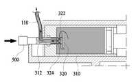
한편, 상기 몸체(100)는 내부에 상기 삽입니들(200)과 후술하는 상기 약물용기(300)가 연통될 수 있도록 하는 별도의 연통노즐(110)이 더 구비된다.The
구체적으로, 상기 연통노즐(110)은 일측이 상기 삽입니들(200)의 일단부와 연결되어 연통되도록 구성되며, 타측이 후술하는 상기 커넥터(500)와 연결되고, 상기 커넥터(500)와 상기 약물용기(300)가 선택적으로 연통됨에 따라 상기 약물용기(300)에 수용된 상기 약물용액이 상기 삽입니들(200)로 전달될 수 있도록 구성된다.Specifically, the
본 실시예에서 상기 연통노즐(110)은 배관형태로 형성되어 일측이 상기 삽입니들(200)과 고정되도록 구성되며, 구체적인 구성은 상기 커넥터(500)와 함께 후술한다.In the present embodiment, the
한편, 상기 삽입니들(200)은, 내부에 약물용액이 유동하는 용액유로(210)가 형성되며, 일측이 상기 몸체(100)에 고정되고 타측이 상기 몸체(100)의 외부로 연장되어 돌출 형성된다.The
구체적으로 본 발명에 따른 상기 삽입니들(200)은 길게 형성되며 길이방향을 따라 내부에 용액유로(210)가 형성되어 후술하는 상기 약물용기(300)에서 전달되는 약물용액을 신체 내부로 주입되도록 구성된다.Specifically, the
본 실시예에서 상기 삽입니들(200)은 원통 형상의 가는 관 형태로 형성되어 타단부가 사용자의 신체 내부로 삽입된다.In the present embodiment, the
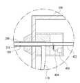
여기서 상기 삽입니들(200) 내부에는 도 5에 도시된 바와 같이 상기 용액유로(210)와 별도로 후술하는 상기 영상측정유닛(400)의 일부가 배치된다. 이때, 상기 삽입니들(200)은 상기 용액유로(210)상에 구비되어 상기 영상측정유닛(400)의 일부가 고정되는 상기 가이드부(202)를 포함한다.5, a portion of the
이때, 상기 가이드부(202)는 상기 용액유로(210) 내부에서 길이방향을 따라 복수 개가 구비될 수 있으며, 각각이 방사형으로 구성되어 상기 영상측정유닛(400)의 일부를 고정할 수 있다.At this time, a plurality of
물론 본 실시예에서와 달리 상기 가이드부(202)는 원통형상으로 길게 형성되거나 하나의 부재로 형성되는 등 다양한 형상을 가질 수 있으며, 상기 용액유로(210) 내에서 상기 영상측정유닛(400)의 일부를 고정할 수 있다면 어떠한 형상이라도 적용될 수 있다.The
한편, 상기 삽입니들(200)은 일측이 상기 몸체(100) 내부에서 상기 연통노즐(110)과 연결되며, 상기 연통노즐(110)은 후술하는 상기 커넥터(500)에 연결된다.One side of the
그리고 상기 연통노즐(110)에 의해 상기 약물용기(300)에 수용된 상기 약물용액이 상기 커넥터(500)와 상기 용액유로(210)를 거치며 인체 내부로 주입될 수 있다.The drug solution contained in the
이와 같이 상기 삽입니들(200)은 타측이 사용자의 신체 내부로 삽입되며, 후술하는 상기 영상측정유닛(400)의 일부가 함께 관통 삽입될 수 있도록 구성된다.As described above, the other side of the
한편, 상기 약물용기(300)는 상기 약물용기(300)가 내부에 수용되며 사용자의 조작에 의해 내부에 수용된 상기 약물용액을 배출할 수 있도록 구성된다.Meanwhile, the
구체적으로 본 발명에 따른 상기 약물용기(300)는 크게 수용부(310) 및 개폐조절부(320)를 포함한다.Specifically, the
상기 수용부(310)는 내부에 공간이 형성되어 상기 약물용액을 수용하고, 일측에 함몰 형성되어 외부와 연통되는 배출구(312)를 포함한다.The
여기서 상기 수용부(310)는 길게 형성되어 상기 몸체(100) 내부에 착탈 가능하도록 장착되며 상기 배출구(312)가 전방으로 향하도록 배치된다.Here, the receiving
그리고 상기 배출구(312)는 후술하는 상기 커넥터(500)가 삽입됨에 따라 상기 수용부(310)의 내부와 상기 연통노즐(110)이 연통되어 상기 약물용액이 상기 용액유로(210)와 연결될 수 있도록 한다.The
본 실시예에서 상기 수용부(310)는 도 3에 도시된 바와 같이 길게 형성되어 일측에 배출구(312)가 형성되며, 상기 배출구(312)상에는 상기 개폐조절부(320)가 슬라이딩 가능하도록 삽입된다.3, an
한편, 상기 개폐조절부(320)는 상기 배출구(312)의 크기에 대응하는 크기를 가지며 길게 형성되어 일측이 차단된 상태로 내부에 배출유로(322)가 형성된다.Meanwhile, the opening /
그리고 일측 끝단부의 둘레상에 상기 배출유로(322)의 내 외부를 연통시키는 연통홀(324)이 형성된다.And a
이때, 상기 개폐조절부(320)에 형성된 상기 배출유로(322)는 일측이 차단되어 있지만, 타측은 전방으로 개구된 상태로 형성된다.At this time, the
즉, 상기 개폐조절부(320)는 길게 관 형태로 형성되어 내부에 상기 배출유로(322)가 형성되고, 일측에는 둘레인 측면에 연통홀(324)이 형성되며 타측은 끝단부가 개구된 형태로 형성된다.That is, the opening /
이와 같이 구성된 상기 개폐조절부(320)는 상기 수용부(310) 내부에서 외부방향으로 상기 배출구(312)에 삽입된다. 여기서, 상기 개폐조절부(320)의 일측은 상기 수용부(310) 내부를 향하도록 배치되고, 타측인 상기 배출구(312)를 향하도록 배치된다.The opening /
그리고 이와 같이 상기 배출구(312)에 삽입된 상기 개폐조절부(320)는 후술하는 상기 커넥터(500)의 조작에 의해 후방으로 슬라이딩하도록 구성된다.The opening /
본 실시예에서 상기 개폐조절부(320)는 도 4에 도시된 바와 같이 T자 형으로 일측이 상기 수용부(310) 내부에 배치되며 둘레가 상기 배출구(312)의 직경보다 상대적으로 크게 형성된다.4, the opening /
그리고 상기 개폐조절부(320)의 일측에는 상기 배출유로(322)와 연통되는 복수 개의 연통홀(324)이 둘레를 따라 연속하여 형성된다.A plurality of
이와 같이 형성된 상기 개폐조절부(320)는 상기 수용부(310) 내부에서 전방으로 슬라이딩한 형태로 삽입된다.The opening /
이에 따라 도 3에 도시된 바와 같이 상기 수용부(310)상에 형성된 상기 배출구(312)는 상기 개폐조절부(320)가 삽입됨에 따라 개방되지 않고 폐쇄되어 내부의 상기 약물용액이 외부로 배출되지 않는다.3, the
구체적으로 상기 개폐조절부(320)의 일측은 차단되어 있는 상태이며, 상기 배출구(312)에 삽입됨에 따라 상기 개폐조절부(320)의 일측 끝단부를 제외하고는 측면이 상기 배출구(312) 내에 배치된 상태이기 때문에 상기 배출구(312)는 상기 수용부(310)의 내부와 완전히 차단된 상태가 된다.Specifically, as one side of the opening /
그리고 후술하는 상기 커넥터(500)에 의해 상기 개폐조절부(320)가 후방으로 슬라이딩하여 상기 수용부(310) 내부와 상기 배출유로(322)가 연통될 수 있으며, 이는 도 6 및 도 7을 참조하여 후술한다.The opening /
이와 같이 상기 약물용기(300)에서 상기 배출구(312)가 차단된 상태로 배치되기 때문에 상기 약물용액이 외부와 차단되며, 이에 따라 의도하지 않게 약물용액의 누수가 발생하거나 외부의 오염물질이 유입되는 것을 방지할 수 있다.Since the
한편, 상기 커넥터(500)는 상기 몸체(100)상에서 상기 약물용기(300)의 전방에 배치되며 길게 형성되어 전후방으로 슬라이딩 가능하도록 구성된다.Meanwhile, the
구체적으로 상기 커넥터(500)는 길이방향에 따른 일측이 외부로 노출되며 타측이 상기 배출구(312)의 전방에 배치되어 사용자의 조작에 의해 전후방으로 슬라이딩한다.Specifically, one side of the
이때, 상기 커넥터(500)는 길이방향에 따른 타측이 개구되어 상기 배출구(312) 내부로 삽입되며, 이와 함께 상기 배출유로(322)와 연통된다.At this time, the other side of the
그리고 상기 커넥터(500)의 길이방향에 따른 중앙부가 상술한 상기 연통노즐(110)에 연결된다.The central portion of the
즉 상기 커넥터(500)는 길게 형성되며 길이방향에 따른 일부가 상기 배출구(312)에 삽입됨으로써 상기 배출유로(322)와 상기 연통노즐(110)이 연통되도록 한다.That is, the
여기서, 상기 커넥터(500)의 타측이 상기 배출구(312) 내부로 삽입됨에 따라 상기 개폐조절부(320)의 타측과 접하여 상기 배출유로(322)와 연통되고, 이와 동시에 상기 개폐조절부(320)는 후방으로 슬라이딩하게 된다.As the other side of the
그리고 상기 개폐조절부(320)가 후방으로 슬라이딩 함으로써, 상기 개폐조절부(320)에 형성된 상기 연통홀(324)이 상기 수용부(310) 내부로 노출된다.The
이에 따라 상기 수용부(310) 내부는 상기 배출유로(322) 및 상기 연통노즐(110)과 연통된다.Accordingly, the inside of the
즉, 상기 커넥터(500)의 일측을 사용자가 조작하여 슬라이딩시킴으로써 상기 약물용기(300)의 배출구(312)가 개방됨과 동시에 상기 커넥터(500)에 의해 상기 배출유로(322)와 상기 연통노즐(110)이 연통된다.That is, one side of the
이에 따라 상기 수용부(310) 내부에 수용된 상기 약물용액은 상기 배출유로(322), 상기 연통노즐(110) 및 상기 용액유로(210)를 거치며 인체 내부로 주입될 수 있도록 구성된다.The drug solution contained in the
여기서, 상기 연통노즐(110)은 후술하는 약물용기(300)를 통해 배출되는 약물용액이 상기 삽입니들(200)로 전달되도록 함과 동시에 상기 약물용기(300)로부터 배출되는 상기 약물용액이 역류하지 않도록 별도의 역류방지수단(미도시)이 더 구비될 수도 있다.Here, the
상기 역류방지수단은 도면에 도시되지는 않았지만, 상기 약물용액이 흐르는 경로상에 구비되어 일 방향으로만 상기 약물용액이 이동할 수 있도록 하며, 다양한 형태로 형성될 수 있다.Although the counterflow preventing means is not shown in the drawing, the counterflow preventing means may be provided in a path through which the drug solution flows to allow the drug solution to move only in one direction, and may be formed in various forms.
이와 같이 상기 연통노즐(110)에 상기 역류방지수단이 구비됨으로써 상기 약물용액의 역류를 방지하여 환자의 안전을 보호할 수 있다.By providing the backflow prevention means in the
본 실시예에서 상기 커넥터(500)는 길게 형성되며 상기 약물용기(300)의 전방에 배치되어 후방슬라이딩을 통해 타측이 상기 배출구(312) 내부로 삽입될 수 있도록 구성된다.In this embodiment, the
그리고 상기 연통노즐(110)은 길이방향에 따른 양단이 각각 상기 용액유로(210) 및 상기 커넥터(500)에 연결됨으로써 상기 배출유로(322)와 상기 용액유로(210)가 연통될 수 있도록 한다.The
이와 같이 본 발명에 따른 상기 커넥터(500)가 구성되며, 상기 커넥터(500)를 통해 상기 약물용기(300)의 개폐가 조절됨과 동시에 상기 수용부(310)가 상기 삽입니들(200)과 연통되도록 한다.The
한편, 상기 영상측정유닛(400)은 상기 몸체(100)상에 배치되며 일부가 길게 형성되어 상기 삽입니들(200)과 함께 인체 내부에 삽입되며, 인체 내부의 영상을 촬영하는 구성으로써. 크게 광원(410), 광전달부(420), 촬영부(430) 및 표시부(440)를 포함한다.The
상기 광원(410)은 상기 몸체(100)상에 구비되어 빛을 발광하는 구성으로써 일반적인 발광장치가 적용될 수 있다.The
본 실시예에서 상기 광원(410)은 도시된 바와 같이 상기 본체에 장착되고, 상기 광전달부(420)와 연결되어 상기 삽입니들(200)을 통해 인체 내부로 빛은 전달하며, 이와 달리 상기 몸체(100) 외부에 별도로 구비될 수도 있다.In the present embodiment, the
한편, 상기 광전달부(420)는 길게 형성되어 복수 개의 광섬유로 구성되며 일부가 상기 광원(410)과 연결되며 상기 용액유로(210) 내부에 배치된다.The
그리고 상기 광전달부(420)는 상기 광원(410)에서 발광되는 빛을 전달받아 상기 삽입니들(200)과 함께 인체 내부에 삽입된 상태로 내부 영상을 전달한다.The
구체적으로 본 발명에 따른 상기 광전달부(420)는 도 5에 도시된 바와 같이 길이방향에 따른 일부가 길게 광섬유형태로 구성되어 발광라인(424) 및 촬영라인(422)으로 이루어지며, 각각이 길게 형성되어 일체로 상기 용액유로(210) 내부에 배치된다.More specifically, as shown in FIG. 5, the
여기서, 상기 발광라인(424)은 상기 광원(410)에 연결되어 빛을 공급받아 빛을 전달하는 구성으로써, 일측이 상기 광원(410)과 연결되고 타측 끝단부에서 전달받은 빛이 출사된다.The
그리고 상기 촬영라인(422)은 상술한 상기 발광라인(424)과 유사하게 형성되며 인체 내부의 영상을 상기 후술하는 상기 촬영부(430)로 전달한다. 구체적으로 상기 촬영라인(422)은 길게 형성되며 타측이 상기 삽입니들(200)상에 배치되고 일측이 상기 표시부(440)에 연결되어 인체 내부에 삽입된 상태에서 영상을 전달한다.The photographing
여기서 상기 발광라인(424) 및 상기 촬영라인(422)은 각각이 복수 개의 광섬유다발로 구성되며 도시된 바와 같이 내부에서 전반사를 통해 빛을 전달한다.The
한편, 상기 촬영부(430)는 상기 몸체(100) 내부에서 상기 광전달부(420)와 인접하게 배치되어 상기 광전달부(420)를 통해 전달되는 영상을 촬영한다.The photographing
구체적으로 상기 촬영부(430)는 일반적인 카메라나 이미지 센서, 대물렌즈형태의 광학렌즈 등으로 구성될 수 있으며, 상기 촬영라인(422)을 통해 전달되는 이미지를 촬영 및 저장한다.Specifically, the photographing
본 실시예에서 상기 촬영부(430)는 복수 개의 렌즈로 구성된 카메라 형태를 포함하며, 상기 몸체(100) 내부에서 상기 촬영라인(422)과 소정거리 이격된 상태로 배치된다.In the present embodiment, the photographing
이와 같이 상기 촬영부(430)는 상기 촬영라인(422)으로부터 전달되는 이미지를 촬영 및 저장하고 후술하는 상기 표시부(440)를 통해 사용자에게 나타낼 수 있도록 한다.As described above, the photographing
한편, 상기 표시부(440)는 상기 몸체(100)의 내부 또는 외부에 구성될 수 있으며, 상기 촬영부(430)를 통해 촬영된 이미지를 사용자가 확인할 수 있도록 표시한다.Meanwhile, the
상기 표시부(440)는 일반적인 디스플레이 화면으로 구성될 수 있으며, 본 실시예에서 도시된 바와 같이 상기 몸체(100) 외부에 배치될 수 있다. 물론 이와 달리 상기 표시부(440)가 상기 몸체(100)와 일체로 구성되지 않고 별도로 분리되어 구비될 수도 있다.The
또한, 추가적으로 상기 몸체(100)상에 구비되며 별도의 외부기기와 선택적으로 연결되어 상기 촬영부(430)에서 촬영된 영상을 상기 외부기기로 전달하는 어댑터(미도시)를 더 포함할 수도 있다.In addition, an adapter (not shown) may be further provided on the
이와 같이 구성된 상기 영상측정유닛(400)은 상기 광전달부(420)가 상기 용액유로(210) 내에 배치되어 상기 삽입니들(200)의 끝단부 이미지를 촬영할 수 있다.In the
이상과 같이 본 발명에 따른 약물주입기는 상기 몸체(100), 상기 삽입니들(200), 상기 약물용기(300), 상기 커넥터(500) 및 상기 영상측정유닛(400)을 포함하며, 사용자의 조작에 의해 상기 약물용기(300)의 개방을 조절함으로써 의도하지 않게 상기 약물용액이 오염되거나 누수가 발생하는 것을 방지할 수 잇다.As described above, the drug injector according to the present invention includes the
또한, 상기 영상측정유닛(400)을 통해 인체 내부에서 상기 삽입니들(200)의 끝단부 위치를 확인하며 약물용액을 주입할 수 있다.Further, the position of the end of the inserted
다음으로, 도 6 및 도 7을 참조하여 본 발명에 따른 상기 약물용기(300)가 개방되는 상태에 대해서 보다 상세하게 살펴보면 다음과 같다.Next, the
도 6 도 1의 약물주입기에서 약물용기(300)와 커넥터(500)가 분리된 상태를 나타낸 도면이고, 도 7은 도 6의 약물주입기에서 커넥터(500)의 일부가 배출구(312)로 삽입되어 연통되는 상태를 나타낸 도면이다.Fig. 6 is a view showing a state in which the
먼저, 도 6을 살펴보면, 상기 커넥터(500)가 상기 약물용기(300)의 전방에 배치된 상태로써, 상기 커넥터(500)가 상기 배출구(312) 내부로 삽입되지 않은 상태가 된다.6, when the
여기서, 상기 수용부(310)상에서 상기 개폐조절부(320)가 전방으로 슬라이딩하여 상기 배출구(312)를 차단하고 있는 상태이다.Here, the opening /
이와 같은 경우 상술한 바와 같이 상기 개폐조절부(320)의 일측이 차단되어 있는 상태이며, 상기 연통홀(324)은 상기 배출구(312)에 의해 차단되어 있으므로, 상기 수용부(310) 내부는 완전히 밀폐 된다.In this case, as described above, one side of the opening /
이는 상기 약물용기(300)의 초기 상태이며, 이와 같이 상기 약물용기(300)는 독립적으로 개폐가 용이하지 않으며, 배출구(312)가 돌출되어 있지 않기 때문에 몸체(100)에 장착 시 간섭이 발생하지 않게 된다.This is an initial state of the
이어서, 도 7을 살펴보면, 사용자의 조작에 의해 상기 커넥터(500)가 후방으로 슬라이딩한 상태이다.Next, referring to FIG. 7, the
여기서 상기 커넥터(500)는 일부가 상기 배출구(312)에 슬라이딩하여 삽입되며, 이와 동시에 상기 개폐조절부(320)를 가압한다.Here, a portion of the
그리고, 상기 개폐조절부(320)가 상기 수용부(310) 내부로 슬라이딩하여 상기 연통홀(324)이 상기 수용부(310) 내부로 노출되며 상기 수용부(310) 내부가 상기 배출유로(322)와 연통된다.The opening and closing
이때, 상기 커넥터(500)는 상기 개폐조절부(320)에 형성된 배출유로(322)와 접하여 연통되고, 이에 따라 상기 배출유로(322)를 통해 상기 수용부(310) 내부와 상기 연통노즐(110)이 연결된다.At this time, the
즉, 상기 커넥터(500)가 슬라이딩하여 상기 배출구(312)에 삽입되는 경우, 상기 커넥터(500)는 상기 배출유로(322)와 연결되고, 이와 함께 상기 개폐조절부(320)가 슬라이딩하여 상기 수용부(310)가 개방됨으로써, 상기 수용부(310)가 상기 용액유로(210)와 연통된다.That is, when the
이에 따라, 상기 수용부(310)에 수용된 상기 약물용액은 도시된 바와 같이 상기 연통홀(324)을 통해 상기 배출유로(322)와 상기 커넥터(500)를 경유하며 상기 연통노즐(110)로 이동하고, 상기 연통노즐(110)을 경유한 상기 약물용액은 상기 용액유로(210)로 이동하여 인체 내부로 주입된다.The drug solution stored in the
이와 같이 본 발명에 따른 약물주입기는 상기 커넥터(500)에 의해 개방되기 전에는 의도하지 않게 개방되어 약물용액의 누수가 발생하지 않는 약물용기(300)를 포함하여 위생적이며 안전하게 사용할 수 있다.
As described above, the drug injector according to the present invention includes a
이상과 같이 본 발명에 따른 바람직한 실시예를 살펴보았으며, 앞서 설명된 실시예 이외에도 본 발명이 그 취지나 범주에서 벗어남이 없이 다른 특정 형태로 구체화 될 수 있다는 사실은 해당 기술에 통상의 지식을 가진 이들에게는 자명한 것이다. 그러므로, 상술된 실시예들은 제한적인 것이 아니라 예시적인 것으로 여겨져야 하고, 이에 따라 본 발명은 상술한 설명에 한정되지 않고 첨부된 청구항의 범주 및 그 동등 범위 내에서 변경될 수도 있다.
It will be apparent to those skilled in the art that the present invention can be embodied in other specific forms without departing from the spirit or scope of the invention as defined in the appended claims. It is obvious to them. Therefore, the above-described embodiments are to be considered as illustrative rather than restrictive, and the invention is not limited to the above description, but may be modified within the scope of the appended claims and equivalents thereof.
100: 몸체
110: 연통노즐
200: 삽입니들
210: 용액유로
300: 약물용기
310: 수용부
320: 개폐조절부
400: 영상측정유닛
410: 광원
420: 광전달부
430: 촬영부
440: 표시부
500: 커넥터100: Body
110: communicating nozzle
200: Insertion needle
210:
300: drug container
310:
320: opening / closing control section
400: image measuring unit
410: Light source
420:
430:
440:
500: Connector
Claims (15)
Translated fromKorean약물용액이 유동하는 용액유로가 형성되며, 상기 몸체 내부에 일측이 고정되고 타측은 상기 몸체 외부로 연장되어 인체에 삽입되는 삽입니들;
상기 약물용액이 수용되며, 일측에 함몰 형성된 배출구를 가지는 수용부 및 길게 형성되어 일측이 차단된 상태로 내부에 배출유로가 형성되고, 상기 배출구상에서 슬라이딩 가능하도록 삽입되는 개폐조절부를 포함하는 약물용기; 및
길게 형성되어 상기 몸체상에서 상기 용액유로와 연통되며 선택적으로 전후방으로 슬라이딩 가능하도록 구성되고, 상기 배출구 내부로 일부가 삽입됨과 동시에 상기 배출유로와 상기 용액유로를 연통시키는 커넥터; 를 포함하며,
상기 배출구를 통해 상기 커넥터의 일부가 삽입 시 상기 개폐조절부가 슬라이딩하여 상기 수용부 내부로 일부가 노출되며 상기 배출유로와 상기 수용부의 내부가 연통되는 것을 특징으로 하는 약물주입기.A body having a receiving space formed therein and provided with a handle for a user to grip;
An insertion needle formed with a solution flow path through which the drug solution flows, one end fixed to the inside of the body and the other end extended to the outside of the body and inserted into the human body;
A drug container containing the drug solution and having an accommodating part having a discharge port formed at one side thereof and an opening and closing part inserted into the discharge port so as to be slidable, And
A connector formed so as to be elongated and communicable with the solution flow path on the body and selectively slidable forward and backward, a part of which is inserted into the discharge port and which communicates the discharge flow path and the solution flow path; / RTI >
Wherein when the connector is partially inserted through the discharge port, the opening / closing control part slides to expose a part of the inside of the receiving part, and the discharge path and the inside of the receiving part communicate with each other.
상기 개폐조절부는,
길이방향에 따른 일측의 둘레를 따라 상기 배출유로와 연통되는 연통홀이 형성되며, 슬라이딩상태에 따라 상기 연통홀이 상기 수용부 내부로 노출되는 것을 특징으로 하는 약물주입기.The method according to claim 1,
The opening /
And a communicating hole communicating with the discharge passage is formed along a circumference of the one side along the longitudinal direction, and the communicating hole is exposed to the inside of the accommodating portion according to a sliding state.
상기 연통홀은,
상기 개폐조절부의 둘레를 따라 복수 개가 연속하여 형성되는 것을 특징으로 하는 약물주입기.3. The method of claim 2,
The communication hole
Wherein a plurality of openings is continuously formed along the circumference of the opening / closing control part.
상기 개폐조절부는,
상기 수용부 내부에 배치되며 길이방향에 따른 일측의 둘레가 상기 배출구의 직경보다 상대적으로 크게 형성되는 것을 특징으로 하는 약물주입기.The method according to claim 1,
The opening /
And a circumference of the one side along the longitudinal direction is formed to be larger than a diameter of the discharge port.
상기 커넥터는,
길이 방향에 따른 일측이 상기 외부로 노출되어 있으며, 사용자의 조작에 의해 타측 일부가 상기 배출구 내부로 삽입되는 것을 특징으로 하는 약물주입기.The method according to claim 1,
Wherein the connector comprises:
Wherein one side along the longitudinal direction is exposed to the outside and a part of the other side is inserted into the discharge port by a user's operation.
상기 몸체는,
길게 형성되어 일측이 상기 용액유로와 연결되고, 타측이 상기 커넥터와 연결되는 연통노즐을 포함하는 것을 특징으로 하는 약물주입기.The method according to claim 1,
The body,
And a communication nozzle having one side connected to the solution flow path and the other side connected to the connector.
상기 연통노즐은,
상기 약물용기에서 배출되는 상기 약물용액의 역류를 방지하는 별도의 역류방지수단을 더 포함하는 것을 특징으로 하는 약물주입기.The method according to claim 6,
The communication nozzle
Further comprising a backflow prevention means for preventing backflow of the drug solution discharged from the drug container.
상기 몸체상에 배치되며 일부가 길게 형성되어 상기 삽입니들과 함께 인체 내부에 삽입되어 영상을 촬영하는 영상측정유닛을 더 포함하는 약물주입기.The method according to claim 1,
Further comprising: an image measuring unit disposed on the body and partially formed in a long length and inserted into the human body together with the insertion needle to capture an image.
상기 영상측정유닛은,
상기 몸체상에서 구비되어 빛을 발광하는 광원;
길게 형성되며 상기 삽입니들 내부에 배치되고, 상기 광원에서 발광되는 빛을 전달받거나 인체 내부 영상을 전달하는 광전달부;
상기 몸체 내부에서 상기 광전달부와 인접하게 배치되어 상기 광전달부를 통해 전달되는 영상을 촬영하는 촬영부; 및
상기 몸체의 외부에 구비되며 상기 촬영부에서 촬영된 영상을 사용자에게 디스플레이 하는 표시부;
를 포함하는 것을 특징으로 하는 약물주입기.9. The method of claim 8,
Wherein the image measuring unit comprises:
A light source provided on the body and emitting light;
A light transmission unit disposed inside the insertion needle and configured to receive light emitted from the light source or transmit an internal image of the human body;
A photographing unit disposed adjacent to the light transmitting unit in the body for photographing an image transmitted through the light transmitting unit; And
A display unit provided on the outside of the body and displaying an image photographed by the photographing unit to a user;
And an injector for injecting the drug.
상기 광전달부는,
상기 광원에 연결되어 인체 내부에서 빛을 발광하는 발광라인 및 인체 내부의 영상을 촬영하여 상기 표시부로 전달하는 촬영라인을 포함하는 것을 특징으로 하는 약물주입기.10. The method of claim 9,
The light-
And a photographing line connected to the light source to photograph a light emitting line that emits light in the inside of the human body and an image of the inside of the human body and transmit the photographed image to the display unit.
상기 영상측정유닛은,
상기 몸체상에 구비되며 별도의 외부기기와 선택적으로 연결되어 상기 촬영부에서 촬영된 영상을 상기 외부기기로 전달하는 어댑터를 더 포함하는 것을 특징으로 하는 약물주입기.10. The method of claim 9,
Wherein the image measuring unit comprises:
Further comprising an adapter provided on the body and selectively connected to a separate external device to transmit an image captured by the imaging unit to the external device.
상기 약물용액이 수용되며, 일측에 함몰 형성된 배출구를 가지는 수용부; 및
길게 형성되어 일측이 차단된 상태로 내부에 배출유로가 형성되고, 상기 배출구상에서 슬라이딩 가능하도록 삽입되는 개폐조절부; 를 포함하며,
상기 커넥터의 일부가 상기 배출구로 삽입됨과 동시에 상기 배출유로와 상기 용액유로를 연통되고, 상기 개폐조절부의 일부가 상기 수용부 내부로 일부가 노출되며 상기 배출유로와 상기 수용부 내부가 연통되는 것을 특징으로 하는 약물용기.A body having a handle for gripping a user and a solution flow path through which the drug solution flows are formed, and one side is fixed to the inside of the body and the other side is extended to the outside of the body, And a connector which is formed to be elongated and communicable with the solution flow path on the body and selectively slidable in forward and backward directions. The present invention relates to a drug container mounted on a drug injector,
A receiving portion for receiving the drug solution and having an outlet formed at one side thereof; And
An opening / closing control part formed in a long shape so that one side thereof is blocked, a discharge flow path is formed therein, and is slidably inserted on the discharge port; / RTI >
A part of the connector is inserted into the discharge port, and at the same time, the discharge passage and the solution passage are communicated with each other, and a part of the opening / closing control section is partially exposed to the inside of the storage section and the discharge passage and the inside of the storage section are communicated Lt; / RTI >
상기 개폐조절부는,
길이방향에 따른 일측의 둘레를 따라 상기 배출유로와 연통되는 연통홀이 형성되며, 슬라이딩상태에 따라 상기 연통홀이 상기 수용부 내부로 노출되는 것을 특징으로 하는 약물용기.13. The method of claim 12,
The opening /
And a communicating hole communicating with the discharge passage is formed along a circumference of the one side along the longitudinal direction, and the communicating hole is exposed to the inside of the accommodating portion according to the sliding state.
상기 연통홀은,
상기 개폐조절부의 둘레를 따라 복수 개가 연속하여 형성되는 것을 특징으로 하는 약물용기.14. The method of claim 13,
The communication hole
Wherein a plurality of the openings are continuously formed along the circumference of the opening / closing control part.
상기 개폐조절부는,
상기 수용부 내부에 배치되며 길이방향에 따른 일측의 둘레가 상기 배출구의 직경보다 상대적으로 크게 형성되는 것을 특징으로 하는 약물용기.13. The method of claim 12,
The opening /
And a peripheral portion disposed in the accommodating portion and extending in a longitudinal direction thereof is formed to have a relatively larger diameter than the diameter of the discharge port.
Priority Applications (1)
| Application Number | Priority Date | Filing Date | Title |
|---|---|---|---|
| KR1020150151185AKR101698353B1 (en) | 2015-10-29 | 2015-10-29 | Cartridge Unit and Drug Infusion Device Having the Same |
Applications Claiming Priority (1)
| Application Number | Priority Date | Filing Date | Title |
|---|---|---|---|
| KR1020150151185AKR101698353B1 (en) | 2015-10-29 | 2015-10-29 | Cartridge Unit and Drug Infusion Device Having the Same |
Publications (1)
| Publication Number | Publication Date |
|---|---|
| KR101698353B1true KR101698353B1 (en) | 2017-01-23 |
Family
ID=57989710
Family Applications (1)
| Application Number | Title | Priority Date | Filing Date |
|---|---|---|---|
| KR1020150151185AActiveKR101698353B1 (en) | 2015-10-29 | 2015-10-29 | Cartridge Unit and Drug Infusion Device Having the Same |
Country Status (1)
| Country | Link |
|---|---|
| KR (1) | KR101698353B1 (en) |
Cited By (1)
| Publication number | Priority date | Publication date | Assignee | Title |
|---|---|---|---|---|
| KR20180098063A (en) | 2017-02-24 | 2018-09-03 | 주식회사 청우메디칼 | A Method for Controlling a Non-inversive Injection of Medical Solution and a Non-Inversive Type of an Apparatus for Injecting Medical Solution |
Citations (4)
| Publication number | Priority date | Publication date | Assignee | Title |
|---|---|---|---|---|
| KR0168313B1 (en)* | 1993-04-14 | 1999-05-01 | 닛폰산소 가부시키가이샤 | Apparatus for reducing dissolved oxygen |
| KR100749266B1 (en)* | 2006-12-29 | 2007-08-13 | 박효남 | Chemical liquid injector |
| JP2013236811A (en)* | 2012-05-16 | 2013-11-28 | Shin Etsu Polymer Co Ltd | Valve element for connector, and the connector |
| KR20150048030A (en)* | 2013-10-24 | 2015-05-06 | 한국생산기술연구원 | Drug Infusion Device Having Bendable Needle |
- 2015
- 2015-10-29KRKR1020150151185Apatent/KR101698353B1/enactiveActive
Patent Citations (4)
| Publication number | Priority date | Publication date | Assignee | Title |
|---|---|---|---|---|
| KR0168313B1 (en)* | 1993-04-14 | 1999-05-01 | 닛폰산소 가부시키가이샤 | Apparatus for reducing dissolved oxygen |
| KR100749266B1 (en)* | 2006-12-29 | 2007-08-13 | 박효남 | Chemical liquid injector |
| JP2013236811A (en)* | 2012-05-16 | 2013-11-28 | Shin Etsu Polymer Co Ltd | Valve element for connector, and the connector |
| KR20150048030A (en)* | 2013-10-24 | 2015-05-06 | 한국생산기술연구원 | Drug Infusion Device Having Bendable Needle |
Cited By (1)
| Publication number | Priority date | Publication date | Assignee | Title |
|---|---|---|---|---|
| KR20180098063A (en) | 2017-02-24 | 2018-09-03 | 주식회사 청우메디칼 | A Method for Controlling a Non-inversive Injection of Medical Solution and a Non-Inversive Type of an Apparatus for Injecting Medical Solution |
Similar Documents
| Publication | Publication Date | Title |
|---|---|---|
| US10751472B2 (en) | Drug injecting implement equipped with sliding attachment unit | |
| US10688294B2 (en) | Portable fluid delivery system | |
| ES2989494T3 (en) | Single-use disposable set connector | |
| US12121708B2 (en) | Safety housing based implant/medicament injecting system | |
| CN102648016A (en) | Intradermal Adapter | |
| US20090318891A1 (en) | Delivery device, system, and method for delivering substances into blood vessels | |
| KR20070114721A (en) | Gateway system | |
| CN113766939B (en) | Intrathecal injector device and needle for delivering medication and method of use | |
| KR20160052761A (en) | Reusable auto-injector | |
| JP6377772B2 (en) | Self-injection device with movable needle shroud | |
| US20140371707A1 (en) | Method and device for insertion of tubing into irrigation and infusion fluid pumps | |
| US20100106097A1 (en) | Drug acceptability indicator | |
| KR20150050525A (en) | Bulking agent applicator for treating female urinary incontinence | |
| KR101698353B1 (en) | Cartridge Unit and Drug Infusion Device Having the Same | |
| KR20200018036A (en) | The Injection Set | |
| KR101520020B1 (en) | Visibility possible drug infusion device | |
| KR101734939B1 (en) | Cartridge Unit and Drug Infusion Device Having the Same | |
| KR101734940B1 (en) | Observing Device Having Sliding Separated Needle Unit | |
| KR101742484B1 (en) | Drug injection apparatus that connectable to various drug container | |
| KR101820387B1 (en) | Drug Infusion Device Having Separated Needle Unit | |
| KR101592341B1 (en) | Drug Infusion Device Having Bendable Needle | |
| GB2575127A (en) | Fluid delivery system | |
| KR102118833B1 (en) | Intravenous catheter | |
| TWI611820B (en) | Fiber injection and suction device | |
| JPWO2007039930A1 (en) | Medical equipment |
Legal Events
| Date | Code | Title | Description |
|---|---|---|---|
| PA0109 | Patent application | Patent event code:PA01091R01D Comment text:Patent Application Patent event date:20151029 | |
| PA0201 | Request for examination | ||
| PE0902 | Notice of grounds for rejection | Comment text:Notification of reason for refusal Patent event date:20160928 Patent event code:PE09021S01D | |
| E701 | Decision to grant or registration of patent right | ||
| PE0701 | Decision of registration | Patent event code:PE07011S01D Comment text:Decision to Grant Registration Patent event date:20170111 | |
| GRNT | Written decision to grant | ||
| PR0701 | Registration of establishment | Comment text:Registration of Establishment Patent event date:20170116 Patent event code:PR07011E01D | |
| PR1002 | Payment of registration fee | Payment date:20170117 End annual number:3 Start annual number:1 | |
| PG1601 | Publication of registration | ||
| FPAY | Annual fee payment | Payment date:20191223 Year of fee payment:4 | |
| PR1001 | Payment of annual fee | Payment date:20191223 Start annual number:4 End annual number:4 | |
| PR1001 | Payment of annual fee | Payment date:20210126 Start annual number:5 End annual number:19 |