KR101693823B1 - Heat dissipation kit and lighting apparatus having the same - Google Patents
Heat dissipation kit and lighting apparatus having the sameDownload PDFInfo
- Publication number
- KR101693823B1 KR101693823B1KR1020150056449AKR20150056449AKR101693823B1KR 101693823 B1KR101693823 B1KR 101693823B1KR 1020150056449 AKR1020150056449 AKR 1020150056449AKR 20150056449 AKR20150056449 AKR 20150056449AKR 101693823 B1KR101693823 B1KR 101693823B1
- Authority
- KR
- South Korea
- Prior art keywords
- heat dissipation
- heat
- module
- light source
- source
- Prior art date
- Legal status (The legal status is an assumption and is not a legal conclusion. Google has not performed a legal analysis and makes no representation as to the accuracy of the status listed.)
- Active
Links
Images


Classifications
- H01L33/642—
- H01L33/647—
- H—ELECTRICITY
- H10—SEMICONDUCTOR DEVICES; ELECTRIC SOLID-STATE DEVICES NOT OTHERWISE PROVIDED FOR
- H10H—INORGANIC LIGHT-EMITTING SEMICONDUCTOR DEVICES HAVING POTENTIAL BARRIERS
- H10H20/00—Individual inorganic light-emitting semiconductor devices having potential barriers, e.g. light-emitting diodes [LED]
- H10H20/80—Constructional details
- H10H20/85—Packages
- H10H20/858—Means for heat extraction or cooling
- H—ELECTRICITY
- H01—ELECTRIC ELEMENTS
- H01L—SEMICONDUCTOR DEVICES NOT COVERED BY CLASS H10
- H01L2924/00—Indexing scheme for arrangements or methods for connecting or disconnecting semiconductor or solid-state bodies as covered by H01L24/00
- H01L2924/10—Details of semiconductor or other solid state devices to be connected
- H01L2924/11—Device type
- H01L2924/12—Passive devices, e.g. 2 terminal devices
- H01L2924/1204—Optical Diode
- H01L2924/12041—LED
Landscapes
- Cooling Or The Like Of Electrical Apparatus (AREA)
Abstract
Translated fromKoreanDescription
Translated fromKorean본 발명은 방열 키트 및 이를 포함하는 발광 장치에 관한 것이다.
The present invention relates to a heat dissipation kit and a light emitting device including the heat dissipation kit.
반도체 소자, 발광 소자 등은 구동 시 다량의 열을 발생시킨다. 이러한 소자들은 조명 장치와 같은 제품에서 발열원으로 작용하는데 제품의 효율 향상을 위해 발열원에 대한 적절한 냉각이 중요하다.Semiconductor devices, light emitting devices, and the like generate a large amount of heat when driven. These devices act as heat sources in products such as lighting devices, and proper cooling of the heat source is important to improve the efficiency of the product.
종래에는 작업 환경 및 제품의 설계 구조에 따라서 미리 방열 방식이 정해져 제품이 제작되었다. 따라서 작업 환경이나 설계 구조가 변경되는 경우 방열 방식을 변경하는 것은 대단히 어려우며, 기존 제품을 폐기하고 새로운 제품을 다시 제작해야 하는 등의 번거로움과 이에 따른 비용이 낭비되는 문제가 있었다.
Conventionally, a heat dissipation method has been determined in advance according to a work environment and a design structure of a product, and a product is manufactured. Therefore, it is very difficult to change the heat dissipation method when the working environment or the design structure is changed, and there is a problem that the existing product is discarded and the new product is rebuilt, and the cost is wasted.
이에 당 기술분야에서는 작업 환경과 설계 구조의 변경에 관계없이 용이하게 방열 방식 및 구조를 변경할 수 있는 방안이 요구되고 있다.Accordingly, there is a need in the art to change the heat dissipation system and structure easily, regardless of changes in the working environment and the design structure.
다만, 본 발명의 목적은 이에만 제한되는 것은 아니며, 명시적으로 언급하지 않더라도 아래에서 설명하는 과제의 해결수단이나 실시 형태로부터 파악될 수 있는 목적이나 효과도 이에 포함된다고 할 것이다.
It should be understood, however, that the scope of the present invention is not limited thereto and that the objects and effects which can be understood from the solution means and the embodiments of the problems described below are also included therein.
본 발명의 일 실시 형태에 따른 발열원의 일측에 장착되는 방열 키트는, 발열원의 일측에 장착되는 방열 키트에 있어서, 상기 방열 키트는, 적어도 하나가 상기 발열원에 탈착이 가능하게 체결되는 방열 모듈; 및 상기 발열원과 상기 방열 모듈에 탈착이 가능하게 체결되어 상기 발열원과 상기 방열 모듈을 고정시키는 체결 수단을 포함하고, 상기 방열 모듈은, 상기 발열원과 대응되는 블록 형태의 구조를 가지며, 상기 체결 수단은, 상기 방열 모듈이 상기 발열원의 일측에 접한 상태에서 상기 방열 모듈과 발열원의 양 측면에 체결되며, 상기 체결 수단은, 상기 발열원과 상기 방열 모듈이 상호 접하는 경계를 가로질러 상기 발열원과 상기 방열 모듈의 각 외측면에 체결되는 연결 브라켓과, 상기 발열원과 상기 방열 모듈의 외측면에 각각 구비되어 상기 연결 브라켓이 삽입되는 체결 홈을 더 포함하며, 상기 체결 홈은, 상기 발열원과 상기 방열 모듈의 외측면 중 서로 대응하는 위치에 각각 구비되며, 상기 발열원과 상기 방열 모듈이 체결된 상태에서 서로 연결되며, 복수의 방열 모듈이 상기 발열원의 일측에 순차적으로 체결되어 적층 구조로 구현되는 경우, 서로 상이한 방식의 방열을 수행하는 2개 이상의 방열 모듈을 적층시켜 방열을 수행하며, 상기 방열 모듈에 배치되는 방열 수단은, 히트 싱크, 모터팬, 냉각제가 흐르는 파이프를 구비한 칠러, 공기 배관 및 펠티에 소자 중 어느 하나를 포함할 수 있다.A heat dissipation kit mounted on one side of a heat source according to an embodiment of the present invention is a heat dissipation kit mounted on one side of a heat source, wherein the heat dissipation kit includes: a heat dissipation module in which at least one heat sink is detachably connected to the heat source; And a fastening means for fastening the heat generating source and the heat dissipating module such that the heat dissipating module and the heat dissipating module are detachably coupled to each other, wherein the heat dissipating module has a block-like structure corresponding to the heat dissipating unit, The heat dissipation module is fastened to both sides of the heat dissipation module and the heat dissipation unit in a state in which the heat dissipation module is in contact with one side of the heat dissipation unit and the fastening unit is disposed between the heat dissipation module and the heat dissipation module And a coupling groove formed on an outer surface of the heat generating source and the heat dissipating module to receive the connection bracket, wherein the coupling groove is formed in an outer surface of the heat generating source and the heat dissipating module, And the heat sink and the heat dissipation module are connected to each other in a state where the heat sink and the heat dissipation module are fastened to each other. And a plurality of heat dissipation modules stacked on one side of the heat dissipation unit in order to realize a stacked structure, two or more heat dissipation modules for performing heat dissipation different from each other are stacked to perform heat dissipation, The heat dissipating means may include any one of a heat sink, a motor fan, a chiller having a pipe through which a coolant flows, an air piping, and a Peltier element.
상기 방열 모듈은 복수개 구비되며, 상기 복수의 방열 모듈은 각각 외측면이 상기 발열원의 외측면과 공면을 이룰 수 있다.The plurality of heat dissipation modules may have a coplanar surface with an outer surface of the heat dissipation unit.
상기 복수의 방열 모듈은 상기 발열원의 일측에 순차적으로 체결되어 적층 구조를 구현하며, 상기 발열원의 발열량에 따라서 상기 적층되는 방열 모듈의 수량이 조절될 수 있다.The plurality of heat dissipation modules may be sequentially coupled to one side of the heat dissipation unit to implement a lamination structure, and the quantity of the heat dissipation modules stacked may be adjusted according to the amount of heat generated by the heat dissipation source.
상기 방열 모듈은 내부 공간을 갖는 케이스, 및 상기 케이스 내에 배치되는 방열 수단을 포함할 수 있다.The heat dissipation module may include a case having an inner space and a heat dissipation means disposed in the case.
삭제delete
삭제delete
삭제delete
본 발명의 일 실시 형태에 따른 발광 장치는, 광원 모듈; 및 상기 광원 모듈의 일측에 장착되는 방열 키트를 포함하며, 상기 방열 키트는, 적어도 하나가 상기 광원 모듈에 탈착이 가능하게 체결되는 방열 모듈; 및 상기 광원 모듈과 상기 방열 모듈에 탈착이 가능하게 체결되어 상기 광원 모듈과 상기 방열 모듈을 고정시키는 체결 수단을 포함하고, 상기 방열 모듈은, 상기 광원 모듈과 대응되는 블록 형태의 구조를 가지며, 상기 체결 수단은, 상기 방열 모듈이 상기 광원 모듈의 일측에 접한 상태에서 상기 방열 모듈과 광원 모듈의 양 측면에 체결되며, 상기 체결 수단은, 상기 광원 모듈과 상기 방열 모듈이 상호 접하는 경계를 가로질러 상기 광원 모듈과 상기 방열 모듈의 각 외측면에 체결되는 연결 브라켓과, 상기 광원 모듈과 상기 방열 모듈의 외측면에 각각 구비되어 상기 연결 브라켓이 삽입되는 체결 홈을 포함하며, 상기 체결 홈은, 상기 광원 모듈과 상기 방열 모듈의 외측면 중 서로 대응하는 위치에 각각 구비되며, 상기 광원 모듈과 상기 방열 모듈이 체결된 상태에서 서로 연결되며, 복수의 방열 모듈이 상기 광원 모듈의 일측에 순차적으로 체결되어 적층 구조로 구현되는 경우, 서로 상이한 방식의 방열을 수행하는 2개 이상의 방열 모듈을 적층시켜 방열을 수행하며, 상기 방열 모듈에 배치되는 방열 수단은, 히트 싱크, 모터팬, 냉각제가 흐르는 파이프를 구비한 칠러, 공기 배관 및 펠티에 소자 중 어느 하나를 포함할 수 있다.A light emitting device according to an embodiment of the present invention includes a light source module; And a heat dissipation kit mounted on one side of the light source module, wherein the heat dissipation kit includes at least one heat dissipation module coupled to the light source module so as to be detachable; And a fixing means for fixing the light source module and the heat dissipation module by being detachably coupled to the light source module and the heat dissipation module, wherein the heat dissipation module has a block-like structure corresponding to the light source module, The fastening means is fastened to both sides of the heat dissipation module and the light source module in a state where the heat dissipation module is in contact with one side of the light source module and the fastening means is arranged to cross the boundary between the light source module and the heat dissipation module A connection bracket which is fastened to the outer surface of the light source module and the heat dissipation module and a coupling groove which is respectively provided on the outer surface of the light source module and the heat dissipation module and into which the connection bracket is inserted, Wherein the light source module and the heat dissipation module are provided at positions corresponding to each other of the module and the outer surface of the heat dissipation module, A plurality of heat dissipation modules connected in series to each other and sequentially stacked on one side of the light source module so as to be stacked, two or more heat dissipation modules performing different heat dissipation are stacked to perform heat dissipation, The heat dissipating means disposed in the heat dissipation module may include any one of a heat sink, a motor fan, a chiller having a pipe through which a coolant flows, an air piping, and a Peltier element.
상기 광원 모듈은, 기판 및 상기 기판상에 배열된 복수의 발광소자를 포함할 수 있다.The light source module may include a substrate and a plurality of light emitting devices arranged on the substrate.
상기 광원 모듈 상에 배치되는 광학소자를 더 포함할 수 있다.And an optical element disposed on the light source module.
본 발명의 일 실시 형태에 따르면, 작업 환경과 설계 구조의 변경에 관계없이 용이하게 방열 방식 및 구조를 변경할 수 있는 방열 키트 및 이를 포함하는 발광 장치가 제공될 수 있다.According to an embodiment of the present invention, a heat dissipation kit and a light emitting device including the heat dissipation kit can be provided that can easily change the heat dissipation method and structure irrespective of the change of the working environment and the design structure.
본 발명의 다양하면서도 유익한 장점과 효과는 상술한 내용에 한정되지 않으며, 본 발명의 구체적인 실시 형태를 설명하는 과정에서 보다 쉽게 이해될 수 있을 것이다.
The various and advantageous advantages and effects of the present invention are not limited to the above description, and can be more easily understood in the course of describing a specific embodiment of the present invention.
도 1은 본 발명의 일 실시 형태에 따른 방열 키트를 개략적으로 나타내는 사시도이다.
도 2는 도 1의 분해사시도이다.
도 3a 및 도 3b는 본 발명의 일 실시 형태에 따른 방열 모듈을 개략적으로 나타내는 사시도 및 단면도이다.
도 4a 및 도 4b는 본 발명의 다른 실시 형태에 따른 방열 모듈을 개략적으로 나타내는 것으로 각각 하부사시도 및 상부사시도이다.
도 5는 도 4b의 단면도이다.
도 6a 및 도 6b는 본 발명의 다른 실시 형태에 따른 방열 모듈을 개략적으로 나타내는 사시도 및 단면도이다.
도 7a 및 도 7b는 본 발명의 다른 실시 형태에 따른 방열 모듈을 개략적으로 나타내는 사시도 및 단면도이다.
도 8a 및 도 8b는 본 발명의 다른 실시 형태에 따른 방열 모듈을 개략적으로 나타내는 사시도 및 단면도이다.
도 9는 본 발명의 다른 실시 형태에 따른 방열 키트를 개략적으로 나타내는 사시도이다.
도 10은 본 발명의 일 실시 형태에 따른 발광 장치를 개략적으로 나타내는 사시도이다.
도 11은 도 10의 분해사시도이다.
도 12는 도 10에서 광원 모듈을 개략적으로 나타내는 분해사시도이다.
도 13은 본 발명의 다른 실시 형태에 따른 발광 장치를 개략적으로 나타내는 사시도이다.1 is a perspective view schematically showing a heat dissipation kit according to an embodiment of the present invention.
2 is an exploded perspective view of FIG.
3A and 3B are a perspective view and a cross-sectional view schematically showing a heat dissipation module according to an embodiment of the present invention.
4A and 4B schematically show a heat dissipation module according to another embodiment of the present invention, respectively, and are a bottom perspective view and a top perspective view, respectively.
FIG. 5 is a cross-sectional view of FIG. 4B. FIG.
6A and 6B are a perspective view and a cross-sectional view schematically showing a heat dissipation module according to another embodiment of the present invention.
7A and 7B are a perspective view and a cross-sectional view schematically showing a heat dissipation module according to another embodiment of the present invention.
8A and 8B are a perspective view and a cross-sectional view schematically showing a heat dissipation module according to another embodiment of the present invention.
9 is a perspective view schematically showing a heat dissipation kit according to another embodiment of the present invention.
10 is a perspective view schematically showing a light emitting device according to an embodiment of the present invention.
11 is an exploded perspective view of Fig.
12 is an exploded perspective view schematically showing the light source module in FIG.
13 is a perspective view schematically showing a light emitting device according to another embodiment of the present invention.
이하, 첨부된 도면을 참조하여 본 발명의 바람직한 실시 형태들을 설명한다. 그러나, 본 발명의 실시형태는 여러 가지 다른 형태로 변형될 수 있으며, 본 발명의 범위가 이하 설명하는 실시 형태로 한정되는 것은 아니다.Hereinafter, preferred embodiments of the present invention will be described with reference to the accompanying drawings. However, the embodiments of the present invention can be modified into various other forms, and the scope of the present invention is not limited to the embodiments described below.
또한, 본 발명의 실시형태는 당해 기술분야에서 평균적인 지식을 가진 자에게 본 발명을 더욱 완전하게 설명하기 위해서 제공되는 것이다. 따라서, 도면에서 요소들의 형상 및 크기 등은 보다 명확한 설명을 위해 과장될 수 있으며, 도면 상의 동일한 부호로 표시되는 요소는 동일한 요소이다. 본 명세서에서, '상', '상부', '상면', '하', '하부', '하면', '측면' 등의 용어는 도면을 기준으로 한 것이며, 실제로는 소자나 구성요소가 배치되는 방향에 따라 달라질 수 있을 것이다.
Further, the embodiments of the present invention are provided to more fully explain the present invention to those skilled in the art. Accordingly, the shapes and sizes of the elements in the drawings may be exaggerated for clarity of description, and the elements denoted by the same reference numerals in the drawings are the same elements. In this specification, terms such as "upper,""upper,""upper,""lower,""lower,""lower,""side," and the like are based on the drawings, It will be possible to change depending on the direction.
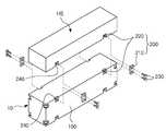
도 1 및 도 2를 참조하여 본 발명의 일 실시 형태에 따른 방열 키트를 설명한다. 도 1은 본 발명의 일 실시 형태에 따른 방열 키트를 개략적으로 나타내는 사시도이고, 도 2는 도 1의 분해사시도이다.
A heat dissipation kit according to an embodiment of the present invention will be described with reference to Figs. 1 and 2. Fig. Fig. 1 is a perspective view schematically showing a heat dissipation kit according to an embodiment of the present invention, and Fig. 2 is an exploded perspective view of Fig. 1. Fig.
도 1 및 도 2를 참조하면, 본 발명의 일 실시 형태에 따른 방열 키트(10)는 발열원(HS)의 일측에 장착되어 상기 발열원(HS)에서 발생된 열을 외부로 방출하는 것으로 상기 발열원(HS)에 체결되는 방열 모듈(100) 및 상기 발열원(HS)과 상기 방열 모듈(100)을 고정시키는 체결 수단(200)을 포함하여 구성될 수 있다.
1 and 2, a
본 실시 형태에서 상기 발열원(HS)은 작동 시 열을 발생시키는 모든 종류의 전자 소자일 수 있다. 예를 들어, 반도체 소자, 발광 소자 등이 상기 발열원(HS)을 이루는 전자 소자에 해당할 수 있으나 이에 한정하는 것은 아니다.
In the present embodiment, the heat source HS may be any type of electronic device that generates heat during operation. For example, a semiconductor device, a light emitting device, or the like may correspond to an electronic device constituting the heat generating source (HS), but the present invention is not limited thereto.
상기 방열 모듈(100)은 복수개로 구성될 수 있으며, 방열 방식에 따라서 선택된 적어도 하나가 상기 발열원(HS)에 탈착이 가능하게 체결될 수 있다. 각 방열 모듈(100)은 서로 상이한 방식으로 방열을 수행하여 상기 발열원(HS)의 열을 외부로 방출할 수 있다.
The
도 3a 및 도 3b에서는 본 발명의 일 실시 형태에 따른 방열 모듈을 개략적으로 나타내고 있다.3A and 3B schematically show a heat dissipation module according to an embodiment of the present invention.
상기 방열 모듈(100A)은 전체적인 외형이 상기 발열원(HS)과 대응되는 블록 형태의 구조를 가지며, 외측면이 상기 발열원(HS)의 외측면과 공면을 이룰 수 있다. 예를 들어, 도면에서 도시하는 바와 같이, 상기 방열 모듈(100A)은 상기 발열원(HS)과 대응되는 직사각형 형태의 블록 구조를 가질 수 있다.
The
상기 방열 모듈(100A)은 내부 공간을 갖는 케이스(110A), 및 상기 케이스(110A) 내에 배치되는 방열 수단(120A)을 포함하여 구성될 수 있다.The
상기 케이스(110A)는 상기 방열 모듈(100A)의 베이스 구조물에 해당하며, 직사각형 형태의 외측면은 상기 발열원(HS)의 외측면과 공면을 이룰 수 있다.The case 110A corresponds to the base structure of the
상기 케이스(110A)는 내열성 재질로 이루어질 수 있으며 이러한 내열성 재질로는, 예를 들어 PPA(Polyphthalamide) 수지를 포함할 수 있다. 다만, 상기 케이스(110A)의 내질이 이에 한정되는 것은 아니며, 예를 들어 알루미늄(Al)과 같은 금속 재질로 이루어지는 것도 가능하다.
The case 110A may be made of a heat-resistant material, and the heat-resistant material may include, for example, PPA (polyphthalamide) resin. However, the inner surface of the case 110A is not limited thereto, and may be made of a metal material such as aluminum (Al).
상기 방열 수단(120A)은 상기 케이스(110A) 내에 배치되며, 상기 발열원(HS)의 열을 외부로 방출시킬 수 있다. 상기 방열 수단(120A)은, 예를 들어, 복수의 방열 핀(121)이 상기 케이스(110A)의 길이 방향을 따라서 배열된 히트 싱크(heat sink)일 수 있다.The heat dissipating unit 120A is disposed in the case 110A and can radiate the heat of the heat source HS to the outside. The heat dissipation means 120A may be a heat sink having a plurality of
상기 케이스(110A)의 하부는 외부로 개방되어 상기 복수의 방열 핀(121)을 외부로 노출시킬 수 있다. 따라서, 상기 발열원(HS)에서 발생된 열은 상기 복수의 방열 핀(121)을 통해 자연 냉각 방식으로 외부로 방출될 수 있다.
The lower portion of the case 110A may be open to the outside to expose the plurality of
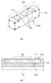
도 4a, 도 4b 및 도 5에서는 본 발명의 다른 실시 형태에 따른 방열 모듈을 개략적으로 나타내고 있다.4A, 4B and 5 schematically show a heat dissipation module according to another embodiment of the present invention.
본 실시 형태에 따른 방열 모듈(100B)은 상기 도 3a 및 도 3b의 방열 모듈(100A)과 마찬가지로 전체적인 외형이 상기 발열원(HS)과 대응되는 블록 형태의 구조를 가지며, 외측면이 상기 발열원(HS)의 외측면과 공면을 이룰 수 있다.
The
상기 방열 모듈(100B)은 내부 공간을 갖는 케이스(110B), 및 상기 케이스(110B) 내에 배치되는 방열 수단(120B)을 포함하여 구성될 수 있다.The
상기 케이스(110B)의 직사각형 형태의 외측면은 상기 발열원(HS)의 외측면과 공면을 이룰 수 있다.
The outer shape of the rectangular shape of the
상기 방열 수단(120B)은 상기 케이스(110B) 내에 배치되며, 상기 발열원(HS)의 열을 외부로 방출시킬 수 있다. 상기 방열 수단(120B)은, 예를 들어, 적어도 하나 이상의 모터 팬(122)일 수 있다.The
상기 모터 팬(122)은 상기 케이스(110B)의 상부와 하부를 관통하는 구조로 외부 노출될 수 있다. 그리고, 상기 케이스(110B)의 상부와 하부에는 각각 공기 순환을 위한 개구(111)가 추가로 마련될 수 있다.The
도 5에서 도시하는 바와 같이, 상기 모터 팬(122)의 회전에 의해 흡입된 외부 공기는 상기 발열원(HS)과 방열 모듈(100B) 사이의 공간과 상기 개구(111)를 강제 순환하며 상기 발열원(HS)에서 발생된 열을 외부로 방출시킬 수 있다.
5, the external air sucked by the rotation of the
도 6a 및 도 6b에서는 본 발명의 다른 실시 형태에 따른 방열 모듈을 개략적으로 나타내고 있다.6A and 6B schematically show a heat dissipation module according to another embodiment of the present invention.
본 실시 형태에 따른 방열 모듈(100C)은 상기 도 3a 및 도 3b의 방열 모듈(100A)과 마찬가지로 전체적인 외형이 상기 발열원(HS)과 대응되는 블록 형태의 구조를 가지며, 외측면이 상기 발열원(HS)의 외측면과 공면을 이룰 수 있다.
The
상기 방열 모듈(100C)은 내부 공간을 갖는 케이스(110C), 및 상기 케이스(110C) 내에 배치되는 방열 수단(120C)을 포함하여 구성될 수 있다.The
상기 케이스(110C)의 직사각형 형태의 외측면은 상기 발열원(HS)의 외측면과 공면을 이룰 수 있다.
The outer shape of the rectangular shape of the
상기 방열 수단(120C)은 냉각제가 흐르는 유로를 이루는 파이프(123)가 상기 케이스(110C)의 내부에 배치되고, 상기 파이프(123)의 양 끝단은 상기 케이스(110C)의 일측 끝단 영역에서 외부로 노출되어 각각 냉각제 유입구(124A) 및 배출구(124B)를 구성하는 칠러(chiller)일 수 있다. 상기 유입구(124A)와 배출구(124B)는 냉각제 저장실(R)과 연결될 수 있다.The heat dissipating means 120C is provided with a
냉각제는 상기 유입구(124A)를 통해 상기 파이프(123) 내부로 유입되고, 상기 파이프(123)를 따라 순환하여 상기 배출구(124B)를 통해 외부로 배출될 수 있다. 상기 발열원(HS)은 순환하는 상기 냉각제에 의해 냉각될 수 있다.
The coolant may be introduced into the
도 7a 및 도 7b에서는 본 발명의 다른 실시 형태에 따른 방열 모듈을 개략적으로 나타내고 있다.7A and 7B schematically show a heat dissipation module according to another embodiment of the present invention.
본 실시 형태에 따른 방열 모듈(100D)은 상기 도 3a 및 도 3b의 방열 모듈(100A)과 마찬가지로 전체적인 외형이 상기 발열원(HS)과 대응되는 블록 형태의 구조를 가지며, 외측면이 상기 발열원(HS)의 외측면과 공면을 이룰 수 있다.
The
상기 방열 모듈(100D)은 내부 공간을 갖는 케이스(110D), 및 상기 케이스(110D) 내에 배치되는 방열 수단(120D)을 포함하여 구성될 수 있다.The
상기 케이스(110D)의 직사각형 형태의 외측면은 상기 발열원(HS)의 외측면과 공면을 이룰 수 있다.
The outer shape of the rectangular shape of the
상기 방열 수단(120D)은 냉각된 차가운 공기가 흐르는 유로를 이루는 배관(125)이 상기 케이스(110D)의 내부에 배치되고, 상기 배관(125)의 양 끝단은 상기 케이스(110D)의 일측 끝단 영역에서 외부로 노출되어 각각 공기 유입구(126A) 및 배출구(126B)를 구성하는 공기 배관(air line)일 수 있다. 상기 유입구(126A)와 배출구(126B)는 압축기(C)와 연결될 수 있다.The heat dissipating means 120D is disposed inside the
상기 공기는 상기 유입구(126A)를 통해 상기 배관(125) 내부로 유입되고, 상기 배관(125)을 따라 순환하여 상기 배출구(126B)를 통해 외부로 배출될 수 있다. 상기 발열원(HS)은 순환하는 상기 공기에 의해 냉각될 수 있다.The air may be introduced into the
한편, 상기 배관(125)이 매립된 상기 케이스(110D)의 하부에는 복수의 방열 핀(127)이 추가로 구비되어 외부로 노출될 수 있다.
Meanwhile, a plurality of
도 8a 및 도 8b에서는 본 발명의 다른 실시 형태에 따른 방열 모듈을 개략적으로 나타내고 있다.8A and 8B schematically show a heat dissipation module according to another embodiment of the present invention.
본 실시 형태에 따른 방열 모듈(100E)은 상기 도 3a 및 도 3b의 방열 모듈(100A)과 마찬가지로 전체적인 외형이 상기 발열원(HS)과 대응되는 블록 형태의 구조를 가지며, 외측면이 상기 발열원(HS)의 외측면과 공면을 이룰 수 있다.
The
상기 방열 모듈(100E)은 내부 공간을 갖는 케이스(110E), 및 상기 케이스(110E) 내에 배치되는 방열 수단(120E)을 포함하여 구성될 수 있다.The
상기 케이스(110E)의 직사각형 형태의 외측면은 상기 발열원(HS)의 외측면과 공면을 이룰 수 있다.
The outer shape of the rectangular shape of the
상기 방열 수단(120E)은 상기 발열원(HS)과 접하는 상기 케이스(110E)의 상부로 냉각면(128)이 노출된 펠티(Peltier)에 소자일 수 있다.The heat dissipating means 120E may be an element of a Peltier in which the
상기 케이스(110E)의 상부에는 적어도 하나 이상의 개구(112)가 구비될 수 있다. 상기 펠티에 소자의 냉각면(128)은 상기 개구(112)를 통해 외부로 노출되고, 상기 발열원(HS)과 접할 수 있다. 상기 발열원(HS)은 상기 펠티에 소자의 구동 시 상기 냉각면(128)에 의해 냉각될 수 있다.
At least one
상기 체결 수단(200)은, 도 1 및 도 2에서 도시하는 바와 같이, 상기 발열원(HS)과 상기 방열 모듈(100)에 탈착이 가능하게 체결되어 상기 발열원(HS)과 상기 방열 모듈(100)을 고정시킬 수 있다.1 and 2, the fastening means 200 is detachably connected to the heat generating source HS and the
상기 체결 수단(200)은 상기 발열원(HS)과 상기 방열 모듈(100)을 서로 고정시키는 연결 브라켓(210), 및 상기 발열원(HS)과 상기 방열 모듈(100)의 외측면에 각각 구비되어 상기 연결 브라켓(210)이 삽입되는 체결 홈(220)을 포함할 수 있다.
The fastening means 200 includes a
상기 연결 브라켓(210)은 상기 발열원(HS)과 상기 발열원(HS)에 체결된 상기 복수의 방열 모듈(100) 중 어느 하나의 방열 모듈(100)이 상호 접하는 경계에서 상기 경계를 가로질러 상기 발열원(HS)과 상기 방열 모듈(100)의 각 외측면에 체결되어 상기 발열원(HS)과 상기 방열 모듈(100)을 서로 고정시킬 수 있다.The
상기 연결 브라켓(210)은, 예를 들어, 양 끝단에 각각 구비되는 나사(230)를 통해 상기 발열원(HS)과 방열 모듈(100)에 각각 탈착이 가능하게 체결되어 고정될 수 있다. 상기 발열원(HS)과 상기 방열 모듈(100)에는 상기 연결 브라켓(210)이 체결되는 위치에 각각 나사홈(240)이 구비될 수 있다.
The
상기 체결 홈(220)은 상기 발열원(HS)과 상기 방열 모듈(100)의 외측면 중 서로 대응하는 위치에 각각 구비되며, 상기 발열원(HS)과 상기 방열 모듈(100)이 체결된 상태에서 서로 연결될 수 있다.The
구체적으로, 상기 체결 홈(220)은 상기 발열원(HS)의 외측면에 소정 깊이로 함몰되되 상기 발열원(HS)의 바닥면을 향해 개방된 구조로 구비될 수 있다. 상기 체결 홈(220)은 상기 발열원(HS)의 서로 대향하는 양측 외측면에 각각 구비되며, 서로 대응하는 위치에 위치할 수 있다. 즉, 상기 발열원(HS)의 중심을 기준으로 좌우 대칭을 이루는 구조를 가질 수 있다.Specifically, the
또한, 상기 체결 홈(220)은 상기 방열 모듈(100)의 외측면에 소정 깊이로 함몰되되 상기 방열 모듈(100)의 상면과 바닥면을 향해 각각 개방된 구조로 구비될 수 있다. 상기 체결 홈(220)은 상기 방열 모듈(100)의 서로 대향하는 양측 외측면에 각각 구비되며, 서로 대응하는 위치에 위치할 수 있다. 즉, 상기 방열 모듈(100)의 중심을 기준으로 상하 및 좌우 대칭을 이루는 구조를 가질 수 있다.
The
상기 발열원(HS)과 방열 모듈(100)이 체결된 상태에서 상기 발열원(HS)에 구비된 체결 홈(220)과 상기 방열 모듈(100)에 구비된 체결 홈(220)은 서로 연결될 수 있다. 또한, 상기 방열 모듈(100)과 다른 방열 모듈(100)이 서로 체결된 상태에서 각 방열 모듈(100)에 구비된 체결 홈(220)은 서로 연결될 수 있다.The
이와 같이 한 쌍의 체결 홈(220)이 서로 연결되어 형성되는 공간은 상기 연결 브라켓(210)과 대응하는 형상을 가질 수 있으며, 상기 연결 브라켓(210)은 상기 공간 내에 삽입되어 끼워질 수 있다.
The space formed by connecting the pair of
상기 연결 브라켓(210)과의 선택적인 체결을 통해서 상기 방열 모듈(100)은 상기 발열원(HS)에 용이하게 탈부착이 가능하게 체결될 수 있다. 따라서, 필요에 따라서 상기 방열 모듈(100)을 용이하게 교체하는 것이 가능하다.
The
이와 같이, 본 실시 형태에 따른 복수의 방열 모듈(100A, 100B, 100C, 100D, 100E) 내에는 각각 상이한 종류의 상기 방열 수단(120A, 120B, 120C, 120D, 120E)이 배치될 수 있다. 그리고, 각 방열 모듈(100A, 100B, 100C, 100D, 100E) 내에 배치되는 상기 방열 수단(120A, 120B, 120C, 120D, 120E)의 종류에 따라서 상기 복수의 방열 모듈(100A, 100B, 100C, 100D, 100E)은 각각 상이한 방식으로 상기 발열원(HS)의 열을 외부로 방출할 수 있다.As described above, different types of the heat dissipating means 120A, 120B, 120C, 120D and 120E may be arranged in the plurality of
따라서, 작업 환경에 따라서 필요한 방열 방식을 구현할 수 있는 방열 모듈을 선택적으로 채택하여 발열원에 장착할 수 있다. 예를 들어, 먼지와 같이 이물질이 많이 발생하는 환경에서는 방열 수단으로 모터 팬 대신에 칠러, 공기 배관 또는 펠티에 소자 중 어느 하나를 적절하게 선택하여 장착할 수 있다.Therefore, a heat dissipation module capable of implementing a necessary heat dissipation system according to a work environment can be selectively adopted and mounted on a heat source. For example, in an environment where a large amount of foreign matter such as dust is generated, any one of chiller, air piping or Peltier element can be appropriately selected and installed instead of a motor fan as a heat radiating means.
또한, 서로 다른 방식으로 방열을 구현하는 복수의 방열 모듈이 규격화된 동일한 블록 형태의 구조를 가지기 때문에 제품의 구조에 따라서 선택하여 체결할 수 있으므로 종래와 같이 방열 방식의 변경에 따른 제품의 폐기 및 재생산의 문제가 발생하지 않는 장점이 있다.
In addition, since a plurality of heat dissipation modules that implement heat dissipation in different ways have the same standardized block structure, they can be selected and fastened according to the structure of the product. Therefore, There is an advantage that the problem of the problem does not occur.
도 9를 참조하여 본 발명의 다른 실시 형태에 따른 방열 키트를 설명한다. 도 9는 본 발명의 일 실시 형태에 따른 방열 키트를 개략적으로 나타내는 사시도이다.
A heat dissipation kit according to another embodiment of the present invention will be described with reference to Fig. 9 is a perspective view schematically showing a heat dissipation kit according to an embodiment of the present invention.
도 9를 참조하면, 본 발명의 일 실시 형태에 따른 방열 키트(20)는 발열원(HS)의 일측에 장착되어 상기 발열원(HS)에서 발생된 열을 외부로 방출하는 것으로 상기 발열원(HS)에 체결되는 복수의 방열 모듈(100) 및 상기 발열원(HS)과 상기 복수의 방열 모듈(100)을 상호 고정시키는 체결 수단(200)을 포함하여 구성될 수 있다.
Referring to FIG. 9, the
상기 복수의 방열 모듈(100)은 상기 발열원(HS)에 탈착이 가능하게 체결될 수 있다. 각 방열 모듈(100)은 서로 상이한 방식으로 방열을 수행하여 상기 발열원(HS)의 열을 외부로 방출할 수 있다.The plurality of
상기 복수의 방열 모듈(100) 및 상기 복수의 방열 모듈(100)을 상호 고정시키고, 상기 발열원(HS)과 상기 복수의 방열 모듈(100)을 고정시키는 상기 체결 수단(200)은 상기 도 1 및 도 2에 도시된 방열 모듈(100) 및 체결 수단(200)과 동일하다. 따라서, 이에 대한 구체적인 설명은 생략한다.
The fastening means 200 for fixing the plurality of
본 실시 형태에 따른 방열 키트(20)는 방열 모듈(100)이 복수개 구비되어 상기 발열원(HS)에 체결되는 점에서 상기 도 1 및 도 2에 도시된 실시 형태에 따른 방열 키트(10)와 차이가 있다.The
즉, 상이한 방열을 구현하는 복수의 방열 모듈(100)은 상기 발열원(HS)의 일측에 순차적으로 체결되어 적층 구조를 구현하며, 상기 발열원(HS)의 발열량에 따라서 상기 적층되는 방열 모듈(100)의 수량이 조절될 수 있다.That is, the plurality of
예를 들어, 상기 발열원(HS)에서 발생되는 열이 증가하여 단일의 방열 모듈(100)로 충분히 냉각시키지 못하는 경우 상기 발열원(HS)의 하부에는 두 개 또는 세 개와 같이 복수의 방열 모듈(100)이 순차적으로 체결되어 적층될 수 있다. 즉, 발열원(HS)의 하부에 체결된 방열 모듈(100)의 하부에 다른 방열 모듈(100)이 추가로 체결될 수 있다. 이 경우 각 방열 모듈(100)은 서로 다른 방식의 방열을 구현하는 방열 모듈로 조합될 수 있다. 예를 들어, 상기 도 3에서 도시하는 방열 모듈(100A)과 상기 도 4에서 도시하는 방열 모듈(100B)을 조합하여 체결시킬 수 있다.
For example, when the heat generated from the heat source HS increases and the heat can not be sufficiently cooled by the single
상기 체결 수단(200)의 연결 브라켓(210)은 상기 발열원(HS)과 상기 발열원(HS)에 체결된 상기 복수의 방열 모듈(100) 중 어느 하나의 방열 모듈(100)이 상호 접하는 경계에서 상기 발열원(HS)과 상기 방열 모듈(100)의 외측면에 각각 체결되어 상기 발열원(HS)과 상기 방열 모듈(100)을 서로 고정시킬 수 있다. 또한, 상기 연결 브라켓(210)은 상기 적층된 방열 모듈(100)이 상호 접하는 경계에서 일측 방열 모듈(100)과 이에 체결된 타측 방열 모듈(100)의 외측면에 각각 체결되어 상기 방열 모듈(100)들을 서로 고정시킬 수 있다.
The connecting
이와 같이, 본 실시 형태에 따른 방열 키트(20)는 발열원(HS)의 발열량에 따라서 발열원(HS)에 체결되는 방열 모듈(100)의 종류 및 수량을 조절함으로써 발열원(HS)에서 발생되는 열을 효과적으로 외부로 방출시켜 발열원(HS)이 과가열되는 것을 방지할 수 있다.As described above, the
또한, 복수의 방열 모듈(100)이 서로 동일한 형태의 블록 구조를 가져 규격화를 이룸으로써 용이한 조립이 가능하다.
In addition, since the plurality of
도 10 내지 도 12를 참조하여 본 발명의 일 실시 형태에 따른 발광 장치를 설명한다. 도 10은 본 발명의 일 실시 형태에 따른 발광 장치를 개략적으로 나타내는 사시도이고, 도 11은 도 10의 분해사시도이며, 도 12는 도 10에서 광원 모듈을 개략적으로 나타내는 분해사시도이다.
A light emitting device according to an embodiment of the present invention will be described with reference to FIGS. 10 to 12. FIG. FIG. 10 is a perspective view schematically showing a light emitting device according to an embodiment of the present invention, FIG. 11 is an exploded perspective view of FIG. 10, and FIG. 12 is an exploded perspective view schematically showing a light source module in FIG.
도 10 및 도 11을 참조하면, 본 발명의 일 실시 형태에 따른 발광 장치(1)는 광원 모듈(30) 및 상기 광원 모듈(30)의 일측에 장착되는 방열 키트(10)를 포함하여 구성될 수 있다. 그리고, 상기 광원 모듈 상에 배치되는 광학 소자(40)를 더 포함할 수 있다.
10 and 11, a
도 12에서 도시하는 바와 같이, 상기 광원 모듈(30)은 기판(31) 및 상기 기판(31) 상에 배열된 복수의 발광소자(32)를 포함할 수 있다. 그리고, 상기 기판(31) 및 복수의 발광소자(32)를 내부에 수납하는 하우징(33)을 더 포함할 수 있다.
12, the
상기 기판(31)은 일반적인 FR4 타입의 인쇄회로기판(PCB) 혹은 변형이 쉬운 플렉서블(flexible) 인쇄회로기판일 수 있고, 에폭시, 트리아진, 실리콘, 및 폴리이미드 등을 함유하는 유기 수지 소재 및 기타 유기 수지 소재로 형성될 수 있다. 또한, 실리콘 나이트라이드, AlN, Al2O3 등의 세라믹 소재로 형성되거나, MCPCB, MCCL 등과 같이 금속 및 금속화합물을 소재로 하여 형성될 수 있다.
The
상기 발광소자(32)는 복수개가 상기 기판(31)상에 실장되어 전기적으로 연결되며, 상기 기판(31)의 길이 방향을 따라서 배열될 수 있다.A plurality of the
상기 발광소자(32)는 외부에서 인가되는 구동 전원에 의해 소정 파장의 광을 발생시키는 광전소자일 수 있다. 예를 들어, n형 반도체층 및 p형 반도체층과 이들 사이에 배치된 활성층을 갖는 반도체 발광다이오드(LED)를 포함할 수 있다The
상기 발광소자(32)는 자외광을 발광하는 UV LED일 수 있다. 또한, 상기 발광소자(32)는 청색광, 녹색광, 또는 적색광을 발광하거나 백색광을 발광할 수도 있다.The
상기 복수의 발광소자(32)는 구동 시 열을 발생시킬 수 있다. 따라서, 상기 광원 모듈(30)은 상기 도 1의 발열원(HS)에 해당할 수 있다.
The plurality of light emitting
상기 광학소자(40)는 상기 광원 모듈(30) 상에 배치되어 상기 복수의 발광소자(32)를 덮을 수 있다.The
상기 광학소자(40)는, 예를 들어 상기 기판(31)의 길이 방향을 따라서 길게 연장된 실린더 렌즈를 포함할 수 있다. 또한, 상기 광학소자(40)는 상기 광원 모듈(30) 상에 배치되는 미도시된 집광 렌즈를 포함할 수도 있다.The
상기 광학소자(40)는 상기 복수의 발광소자(32)에서 발생된 광을 조사방향을 향해 균일하게 확산시킬 수 있다.The
상기 광학소자(40)는 투광성을 갖는 수지 재질로 이루어질 수 있으며, 예를 들어, 폴리카보네이트(polycarbonate, PC), 폴리메틸메타크릴레이트(PMMA), 아크릴(acrylic) 등을 포함할 수 있다. 또한, 글라스 재질로 이루어질 수도 있으나, 이에 한정하는 것은 아니다.
The
상기 광학소자(40)는 선택적으로 구비될 수 있다. 따라서, 실시 형태에 따라 상기 광학소자(40)는 생략될 수 있다. 또한, 실시 형태에 따라서 상기 광원 모듈(30) 상에는 상기 광학소자(40) 대신에 투광성의 커버 부재(미도시)가 구비되어 상기 복수의 발광소자(32)를 덮어 보호할 수도 있다.
The
상기 방열 키트(10)는 상기 광원 모듈(30)에 적어도 하나가 탈착이 가능하게 체결되며 상기 광원 모듈(30)의 열을 외부로 방출하는 방열 모듈(100), 및 상기 광원 모듈(30)과 상기 방열 모듈(100)에 탈착이 가능하게 체결되어 상기 광원 모듈(30)과 상기 적어도 하나의 방열 모듈(100)을 고정시키는 체결 수단(200)을 포함하여 구성될 수 있다.The
상기 방열 키트(10)의 구성 및 구조는 상기 도 1 내지 도 8에 도시된 방열 키트(10)와 기본 구성 및 구조가 실질적으로 동일하므로 이에 대한 구체적인 설명은 생략한다.
Since the structure and structure of the
도 13을 참조하여 본 발명의 다른 실시 형태에 따른 발광 장치를 설명한다. 도 13은 본 발명의 다른 실시 형태에 따른 발광 장치를 개략적으로 나타내는 사시도이다.A light emitting device according to another embodiment of the present invention will be described with reference to Fig. 13 is a perspective view schematically showing a light emitting device according to another embodiment of the present invention.
도 13을 참조하면, 본 발명의 일 실시 형태에 따른 발광 장치(1')는 광원 모듈(30) 및 상기 광원 모듈(30)의 일측에 장착되는 방열 키트(20)를 포함하여 구성될 수 있다. 그리고, 상기 광원 모듈 상에 배치되는 광학 소자(40)를 더 포함할 수 있다.
13, a light emitting device 1 'according to an embodiment of the present invention may include a
상기 광원 모듈(30)은 기판(31) 및 상기 기판(31) 상에 배열된 복수의 발광소자(32)를 포함할 수 있다. 그리고, 상기 기판(31) 및 복수의 발광소자(32)를 내부에 수납하는 하우징(33)을 더 포함할 수 있다.The
상기 광원 모듈(30)은 상기 도 12에 도시된 광원 모듈(30)과 실질적으로 동일하므로 이에 대한 설명은 생략한다.
Since the
상기 광학소자(40)는 상기 광원 모듈(30) 상에 배치되어 상기 복수의 발광소자(32)를 덮을 수 있다. 상기 광학소자(40)는 상기 도 10 및 도 11에 도시된 광학소자(40)와 실질적으로 동일하므로 이에 대한 설명은 생략한다.
The
상기 방열 키트(20)는 상기 광원 모듈(30)에 탈착이 가능하게 체결되며 상기 광원 모듈(30)의 열을 외부로 방출하는 복수의 방열 모듈(100), 및 상기 광원 모듈(30)과 상기 방열 모듈(100) 및 상기 복수의 방열 모듈(100)에 탈착이 가능하게 체결되어 상기 광원 모듈(30)과 상기 적어도 하나의 방열 모듈(100) 및 상기 복수의 방열 모듈(100)들을 상호 고정시키는 체결 수단(200)을 포함하여 구성될 수 있다.The
상기 방열 키트(20)의 구성 및 구조는 상기 도 9에 도시된 방열 키트(20)와 기본 구성 및 구조가 실질적으로 동일하므로 이에 대한 구체적인 설명은 생략한다.
Since the structure and structure of the
이상에서 본 발명의 실시 형태에 대하여 상세하게 설명하였지만 본 발명의 권리범위는 이에 한정되는 것은 아니고, 청구범위에 기재된 본 발명의 기술적 사상을 벗어나지 않는 범위 내에서 다양한 수정 및 변형이 가능하다는 것은 당 기술분야의 통상의 지식을 가진 자에게는 자명할 것이다.
Although the embodiments of the present invention have been described in detail, it is to be understood that the scope of the present invention is not limited thereto and that various modifications and changes may be made thereto without departing from the scope of the present invention. It will be obvious to those of ordinary skill in the art.
1, 1'... 발광 장치
10, 20... 방열 키트
30... 광원 모듈
40... 광학소자
100... 방열 모듈
200... 체결 수단1, 1 '... light emitting device
10, 20 ... heat dissipation kit
30 ... light source module
40 ... optical element
100 ... heat dissipation module
200 ... fastening means
Claims (12)
Translated fromKorean상기 방열 키트는,
적어도 하나가 상기 발열원에 탈착이 가능하게 체결되는 방열 모듈; 및
상기 발열원과 상기 방열 모듈에 탈착이 가능하게 체결되어 상기 발열원과 상기 방열 모듈을 고정시키는 체결 수단을 포함하고,
상기 방열 모듈은, 상기 발열원과 대응되는 블록 형태의 구조를 가지며,
상기 체결 수단은, 상기 방열 모듈이 상기 발열원의 일측에 접한 상태에서 상기 방열 모듈과 발열원의 양 측면에 체결되며,
상기 체결 수단은, 상기 발열원과 상기 방열 모듈이 상호 접하는 경계를 가로질러 상기 발열원과 상기 방열 모듈의 각 외측면에 체결되는 연결 브라켓과, 상기 발열원과 상기 방열 모듈의 외측면에 각각 구비되어 상기 연결 브라켓이 삽입되는 체결 홈을 더 포함하며,
상기 체결 홈은, 상기 발열원과 상기 방열 모듈의 외측면 중 서로 대응하는 위치에 각각 구비되며, 상기 발열원과 상기 방열 모듈이 체결된 상태에서 서로 연결되며,
복수의 방열 모듈이 상기 발열원의 일측에 순차적으로 체결되어 적층 구조로 구현되는 경우, 서로 상이한 방식의 방열을 수행하는 2개 이상의 방열 모듈을 적층시켜 방열을 수행하며,
상기 방열 모듈에 배치되는 방열 수단은, 히트 싱크, 모터팬, 냉각제가 흐르는 파이프를 구비한 칠러, 공기 배관 및 펠티에 소자 중 어느 하나를 포함하는 것을 특징으로 하는 방열 키트.
A heat dissipation kit mounted on one side of a heat source,
In the heat dissipation kit,
A heat dissipation module in which at least one is detachably coupled to the heat source; And
And a fastening means fastened to the heat generating source and the heat dissipating module in a detachable manner to fix the heat generating source and the heat dissipating module,
The heat dissipation module has a block-like structure corresponding to the heat source,
Wherein the fastening means is fastened to both sides of the heat dissipation module and the heat source in a state where the heat dissipation module is in contact with one side of the heat source,
The coupling means includes a connection bracket that is connected to outer surfaces of the heat generating source and the heat dissipating module across the boundary between the heat generating source and the heat dissipating module, Further comprising a fastening groove into which the bracket is inserted,
And the heat sink and the heat dissipation module are connected to each other at a position corresponding to the heat sink and the outer surface of the heat dissipation module,
The plurality of heat dissipation modules are sequentially stacked on one side of the heat source to form a stacked structure, two or more heat dissipation modules that perform different types of heat dissipation are stacked to perform heat dissipation,
Wherein the heat dissipation means disposed in the heat dissipation module includes any one of a heat sink, a motor fan, a chiller having a pipe through which a coolant flows, an air pipe, and a Peltier element.
상기 방열 모듈은 복수개 구비되며, 상기 복수의 방열 모듈은 각각 외측면이 상기 발열원의 외측면과 공면을 이루는 것을 특징으로 하는 방열 키트.
The method according to claim 1,
Wherein a plurality of the heat dissipation modules are provided, and each of the plurality of heat dissipation modules forms a coplanar surface with an outer surface of the heat dissipation unit.
상기 복수의 방열 모듈은 상기 발열원의 일측에 순차적으로 체결되어 적층 구조를 구현하며, 상기 발열원의 발열량에 따라서 상기 적층되는 방열 모듈의 수량이 조절되는 것을 특징으로 하는 방열 키트.
3. The method of claim 2,
Wherein the plurality of heat dissipation modules are sequentially coupled to one side of the heat source to realize a laminate structure, and the quantity of the heat dissipation modules stacked is controlled according to a heat amount of the heat source.
상기 방열 모듈은 내부 공간을 갖는 케이스, 및 상기 케이스 내에 배치되는 방열 수단을 포함하는 것을 특징으로 하는 방열 키트.
4. The method according to any one of claims 1 to 3,
Wherein the heat dissipation module includes a case having an internal space, and a heat dissipation means disposed in the case.
상기 광원 모듈의 일측에 장착되는 방열 키트를 포함하며,
상기 방열 키트는,
적어도 하나가 상기 광원 모듈에 탈착이 가능하게 체결되는 방열 모듈; 및
상기 광원 모듈과 상기 방열 모듈에 탈착이 가능하게 체결되어 상기 광원 모듈과 상기 방열 모듈을 고정시키는 체결 수단을 포함하고,
상기 방열 모듈은, 상기 광원 모듈과 대응되는 블록 형태의 구조를 가지며,
상기 체결 수단은, 상기 방열 모듈이 상기 광원 모듈의 일측에 접한 상태에서 상기 방열 모듈과 광원 모듈의 양 측면에 체결되며,
상기 체결 수단은, 상기 광원 모듈과 상기 방열 모듈이 상호 접하는 경계를 가로질러 상기 광원 모듈과 상기 방열 모듈의 각 외측면에 체결되는 연결 브라켓과, 상기 광원 모듈과 상기 방열 모듈의 외측면에 각각 구비되어 상기 연결 브라켓이 삽입되는 체결 홈을 포함하며,
상기 체결 홈은, 상기 광원 모듈과 상기 방열 모듈의 외측면 중 서로 대응하는 위치에 각각 구비되며, 상기 광원 모듈과 상기 방열 모듈이 체결된 상태에서 서로 연결되며,
복수의 방열 모듈이 상기 광원 모듈의 일측에 순차적으로 체결되어 적층 구조로 구현되는 경우, 서로 상이한 방식의 방열을 수행하는 2개 이상의 방열 모듈을 적층시켜 방열을 수행하며,
상기 방열 모듈에 배치되는 방열 수단은, 히트 싱크, 모터팬, 냉각제가 흐르는 파이프를 구비한 칠러, 공기 배관 및 펠티에 소자 중 어느 하나를 포함하는 것을 특징으로 하는 발광 장치.
A light source module; And
And a heat dissipation kit mounted on one side of the light source module,
In the heat dissipation kit,
At least one of which is detachably coupled to the light source module; And
And a fastening means fastened to the light source module and the heat dissipation module in a detachable manner to fix the light source module and the heat dissipation module,
The heat dissipation module has a block-like structure corresponding to the light source module,
The fastening means is fastened to both sides of the heat dissipation module and the light source module in a state where the heat dissipation module is in contact with one side of the light source module,
The fixing means includes a connection bracket which is fastened to outer surfaces of the light source module and the heat dissipation module across the boundary between the light source module and the heat dissipation module, And a coupling groove into which the connection bracket is inserted,
Wherein the coupling grooves are respectively provided at positions corresponding to each other of the light source module and the outer surface of the heat dissipation module and are connected to each other in a state where the light source module and the heat dissipation module are fastened,
In the case where a plurality of heat dissipation modules are sequentially stacked on one side of the light source module and are realized in a stacked structure, two or more heat dissipation modules performing different heat dissipation are stacked to perform heat dissipation,
Wherein the heat dissipating means disposed in the heat dissipation module includes any one of a heat sink, a motor fan, a chiller having a pipe through which a coolant flows, an air pipe, and a Peltier element.
상기 광원 모듈은, 기판 및 상기 기판상에 배열된 복수의 발광소자를 포함하는 발광 장치.
9. The method of claim 8,
Wherein the light source module includes a substrate and a plurality of light emitting elements arranged on the substrate.
상기 광원 모듈 상에 배치되는 광학소자를 더 포함하는 발광 장치.
9. The method of claim 8,
And an optical element disposed on the light source module.
Priority Applications (2)
| Application Number | Priority Date | Filing Date | Title |
|---|---|---|---|
| KR1020150056449AKR101693823B1 (en) | 2015-04-22 | 2015-04-22 | Heat dissipation kit and lighting apparatus having the same |
| PCT/KR2015/009760WO2016171342A1 (en) | 2015-04-22 | 2015-09-17 | Heat dissipation kit and light emitting device including same |
Applications Claiming Priority (1)
| Application Number | Priority Date | Filing Date | Title |
|---|---|---|---|
| KR1020150056449AKR101693823B1 (en) | 2015-04-22 | 2015-04-22 | Heat dissipation kit and lighting apparatus having the same |
Publications (2)
| Publication Number | Publication Date |
|---|---|
| KR20160126128A KR20160126128A (en) | 2016-11-02 |
| KR101693823B1true KR101693823B1 (en) | 2017-01-10 |
Family
ID=57143237
Family Applications (1)
| Application Number | Title | Priority Date | Filing Date |
|---|---|---|---|
| KR1020150056449AActiveKR101693823B1 (en) | 2015-04-22 | 2015-04-22 | Heat dissipation kit and lighting apparatus having the same |
Country Status (2)
| Country | Link |
|---|---|
| KR (1) | KR101693823B1 (en) |
| WO (1) | WO2016171342A1 (en) |
Family Cites Families (5)
| Publication number | Priority date | Publication date | Assignee | Title |
|---|---|---|---|---|
| KR20090046370A (en)* | 2007-11-06 | 2009-05-11 | (주)세오전자 | LED lamp using the combination of heat dissipation module and heat dissipation module |
| US20110305020A1 (en)* | 2010-06-09 | 2011-12-15 | Chin-Wen WANG & LEADER TREND TECHNOLOGY CORP. | Led lamp and heat-dissipating assembly thereof |
| KR101360730B1 (en)* | 2011-12-02 | 2014-02-07 | 엘지이노텍 주식회사 | Cooling device and electronic device thereof |
| EP2962526B1 (en)* | 2013-04-28 | 2018-05-30 | BYD Company Limited | Electric heater, defroster, heating and air conditioning system and vehicle |
| KR101495101B1 (en)* | 2014-04-03 | 2015-02-25 | 유버 주식회사 | Hybrid type radiating device |
- 2015
- 2015-04-22KRKR1020150056449Apatent/KR101693823B1/enactiveActive
- 2015-09-17WOPCT/KR2015/009760patent/WO2016171342A1/ennot_activeCeased
Also Published As
| Publication number | Publication date |
|---|---|
| WO2016171342A1 (en) | 2016-10-27 |
| KR20160126128A (en) | 2016-11-02 |
Similar Documents
| Publication | Publication Date | Title |
|---|---|---|
| CN101619822B (en) | Lighting device | |
| JP6057543B2 (en) | Lighting device | |
| US10330303B2 (en) | Light emitting device module with heat-sink and air guide | |
| CN105444076B (en) | LED illumination device | |
| US8931934B2 (en) | LED lamp with vertical airflow channel | |
| US20110216536A1 (en) | Illumination device | |
| JP6862803B2 (en) | Irradiation device | |
| US9521777B2 (en) | Cooling system for electronic components and led lamp having the same | |
| KR101412958B1 (en) | Light emitting module and illuminating apparatus comprising the same | |
| US8262254B2 (en) | Carrier structure for mounting LED chips | |
| US9115874B2 (en) | Optical semiconductor illuminating apparatus | |
| CN101650010A (en) | LED light source module and light machine applied by same | |
| US20100328949A1 (en) | Illumination device | |
| EP2267355A1 (en) | LED illuminating apparatus | |
| JP6634848B2 (en) | Irradiation device and heat radiation unit | |
| KR101693823B1 (en) | Heat dissipation kit and lighting apparatus having the same | |
| KR101785643B1 (en) | heat dissipating system of light emitting device | |
| KR101585376B1 (en) | Led lighting having ladiant heat apparatus | |
| KR20120010653A (en) | Lighting device | |
| TWM548768U (en) | Dual-effect heat dissipation type lighting lamp | |
| KR101446122B1 (en) | Improved hit sink and led lighting device using the same | |
| KR20160100712A (en) | A LED lighting apparatus with direct cooling system | |
| KR101833221B1 (en) | Lighting device | |
| KR20160057673A (en) | Liquid Cooling Apparatus for Heat Dissipation of high Power Light Emitting Diode | |
| KR102018660B1 (en) | Lighting module array |
Legal Events
| Date | Code | Title | Description |
|---|---|---|---|
| A201 | Request for examination | ||
| PA0109 | Patent application | Patent event code:PA01091R01D Comment text:Patent Application Patent event date:20150422 | |
| PA0201 | Request for examination | ||
| PE0902 | Notice of grounds for rejection | Comment text:Notification of reason for refusal Patent event date:20160128 Patent event code:PE09021S01D | |
| PE0601 | Decision on rejection of patent | Patent event date:20160826 Comment text:Decision to Refuse Application Patent event code:PE06012S01D Patent event date:20160128 Comment text:Notification of reason for refusal Patent event code:PE06011S01I | |
| PX0901 | Re-examination | Patent event code:PX09011S01I Patent event date:20160826 Comment text:Decision to Refuse Application Patent event code:PX09012R01I Patent event date:20160328 Comment text:Amendment to Specification, etc. | |
| PX0701 | Decision of registration after re-examination | Patent event date:20161028 Comment text:Decision to Grant Registration Patent event code:PX07013S01D Patent event date:20160923 Comment text:Amendment to Specification, etc. Patent event code:PX07012R01I Patent event date:20160826 Comment text:Decision to Refuse Application Patent event code:PX07011S01I Patent event date:20160328 Comment text:Amendment to Specification, etc. Patent event code:PX07012R01I | |
| PG1501 | Laying open of application | ||
| GRNT | Written decision to grant | ||
| PR0701 | Registration of establishment | Comment text:Registration of Establishment Patent event date:20170102 Patent event code:PR07011E01D | |
| PR1002 | Payment of registration fee | Payment date:20170103 End annual number:3 Start annual number:1 | |
| PG1601 | Publication of registration | ||
| FPAY | Annual fee payment | Payment date:20200102 Year of fee payment:4 | |
| PR1001 | Payment of annual fee | Payment date:20200102 Start annual number:4 End annual number:4 | |
| PR1001 | Payment of annual fee | Payment date:20210104 Start annual number:5 End annual number:5 | |
| PR1001 | Payment of annual fee | Payment date:20220103 Start annual number:6 End annual number:6 | |
| PR1001 | Payment of annual fee | Payment date:20230102 Start annual number:7 End annual number:7 |