KR101692467B1 - Surgical Suture And Manufacture Method And Apparatus Of That - Google Patents
Surgical Suture And Manufacture Method And Apparatus Of ThatDownload PDFInfo
- Publication number
- KR101692467B1 KR101692467B1KR1020150043284AKR20150043284AKR101692467B1KR 101692467 B1KR101692467 B1KR 101692467B1KR 1020150043284 AKR1020150043284 AKR 1020150043284AKR 20150043284 AKR20150043284 AKR 20150043284AKR 101692467 B1KR101692467 B1KR 101692467B1
- Authority
- KR
- South Korea
- Prior art keywords
- winding
- yarn
- embossing
- thread
- tension
- Prior art date
- Legal status (The legal status is an assumption and is not a legal conclusion. Google has not performed a legal analysis and makes no representation as to the accuracy of the status listed.)
- Active
Links
- 238000000034methodMethods0.000titleclaimsabstractdescription30
- 238000004519manufacturing processMethods0.000titleabstractdescription33
- 238000004804windingMethods0.000claimsabstractdescription107
- 238000004049embossingMethods0.000claimsabstractdescription35
- 230000001105regulatory effectEffects0.000claimsdescription10
- 230000001276controlling effectEffects0.000claimsdescription3
- 230000000630rising effectEffects0.000claimsdescription2
- 238000010276constructionMethods0.000claims1
- 238000005520cutting processMethods0.000abstractdescription11
- 230000000694effectsEffects0.000abstractdescription10
- 230000037303wrinklesEffects0.000description7
- 238000007665saggingMethods0.000description5
- 230000003247decreasing effectEffects0.000description4
- 238000005452bendingMethods0.000description3
- 238000009956embroideringMethods0.000description3
- 230000004048modificationEffects0.000description3
- 238000012986modificationMethods0.000description3
- 230000009759skin agingEffects0.000description3
- CIWBSHSKHKDKBQ-JLAZNSOCSA-NAscorbic acidChemical compoundOC[C@H](O)[C@H]1OC(=O)C(O)=C1OCIWBSHSKHKDKBQ-JLAZNSOCSA-N0.000description2
- 102000008186CollagenHuman genes0.000description2
- 108010035532CollagenProteins0.000description2
- OENHQHLEOONYIE-UKMVMLAPSA-Nall-trans beta-caroteneNatural productsCC=1CCCC(C)(C)C=1/C=C/C(/C)=C/C=C/C(/C)=C/C=C/C=C(C)C=CC=C(C)C=CC1=C(C)CCCC1(C)COENHQHLEOONYIE-UKMVMLAPSA-N0.000description2
- TUPZEYHYWIEDIH-WAIFQNFQSA-Nbeta-caroteneNatural productsCC(=C/C=C/C=C(C)/C=C/C=C(C)/C=C/C1=C(C)CCCC1(C)C)C=CC=C(/C)C=CC2=CCCCC2(C)CTUPZEYHYWIEDIH-WAIFQNFQSA-N0.000description2
- 235000013734beta-caroteneNutrition0.000description2
- 239000011648beta-caroteneSubstances0.000description2
- 229960002747betacaroteneDrugs0.000description2
- 229920001436collagenPolymers0.000description2
- 239000000470constituentSubstances0.000description2
- 238000009958sewingMethods0.000description2
- GVJHHUAWPYXKBD-IEOSBIPESA-Nα-tocopherolChemical compoundOC1=C(C)C(C)=C2O[C@@](CCC[C@H](C)CCC[C@H](C)CCCC(C)C)(C)CCC2=C1CGVJHHUAWPYXKBD-IEOSBIPESA-N0.000description2
- OENHQHLEOONYIE-JLTXGRSLSA-Nβ-CaroteneChemical compoundCC=1CCCC(C)(C)C=1\C=C\C(\C)=C\C=C\C(\C)=C\C=C\C=C(/C)\C=C\C=C(/C)\C=C\C1=C(C)CCCC1(C)COENHQHLEOONYIE-JLTXGRSLSA-N0.000description2
- KIUKXJAPPMFGSW-DNGZLQJQSA-N(2S,3S,4S,5R,6R)-6-[(2S,3R,4R,5S,6R)-3-Acetamido-2-[(2S,3S,4R,5R,6R)-6-[(2R,3R,4R,5S,6R)-3-acetamido-2,5-dihydroxy-6-(hydroxymethyl)oxan-4-yl]oxy-2-carboxy-4,5-dihydroxyoxan-3-yl]oxy-5-hydroxy-6-(hydroxymethyl)oxan-4-yl]oxy-3,4,5-trihydroxyoxane-2-carboxylic acidChemical compoundCC(=O)N[C@H]1[C@H](O)O[C@H](CO)[C@@H](O)[C@@H]1O[C@H]1[C@H](O)[C@@H](O)[C@H](O[C@H]2[C@@H]([C@@H](O[C@H]3[C@@H]([C@@H](O)[C@H](O)[C@H](O3)C(O)=O)O)[C@H](O)[C@@H](CO)O2)NC(C)=O)[C@@H](C(O)=O)O1KIUKXJAPPMFGSW-DNGZLQJQSA-N0.000description1
- ZZZCUOFIHGPKAK-UHFFFAOYSA-ND-erythro-ascorbic acidNatural productsOCC1OC(=O)C(O)=C1OZZZCUOFIHGPKAK-UHFFFAOYSA-N0.000description1
- 229920002683GlycosaminoglycanPolymers0.000description1
- 229930003268Vitamin CNatural products0.000description1
- 230000002159abnormal effectEffects0.000description1
- 238000009825accumulationMethods0.000description1
- 230000032683agingEffects0.000description1
- 229940087168alpha tocopherolDrugs0.000description1
- 230000003078antioxidant effectEffects0.000description1
- 230000015572biosynthetic processEffects0.000description1
- 239000002537cosmeticSubstances0.000description1
- 239000000835fiberSubstances0.000description1
- 230000036074healthy skinEffects0.000description1
- 229920002674hyaluronanPolymers0.000description1
- 229960003160hyaluronic acidDrugs0.000description1
- 230000037431insertionEffects0.000description1
- 238000003780insertionMethods0.000description1
- 239000000463materialSubstances0.000description1
- 230000035772mutationEffects0.000description1
- 229910052760oxygenInorganic materials0.000description1
- 239000001301oxygenSubstances0.000description1
- 230000000149penetrating effectEffects0.000description1
- 231100000614poisonToxicity0.000description1
- 238000003825pressingMethods0.000description1
- 230000001737promoting effectEffects0.000description1
- 102000004169proteins and genesHuman genes0.000description1
- 108090000623proteins and genesProteins0.000description1
- 230000037394skin elasticityEffects0.000description1
- 230000036560skin regenerationEffects0.000description1
- 239000000126substanceSubstances0.000description1
- 229960000984tocofersolanDrugs0.000description1
- 239000003440toxic substanceSubstances0.000description1
- 235000019154vitamin CNutrition0.000description1
- 239000011718vitamin CSubstances0.000description1
- 239000002076α-tocopherolSubstances0.000description1
- 235000004835α-tocopherolNutrition0.000description1
Images


Classifications
- A—HUMAN NECESSITIES
- A61—MEDICAL OR VETERINARY SCIENCE; HYGIENE
- A61F—FILTERS IMPLANTABLE INTO BLOOD VESSELS; PROSTHESES; DEVICES PROVIDING PATENCY TO, OR PREVENTING COLLAPSING OF, TUBULAR STRUCTURES OF THE BODY, e.g. STENTS; ORTHOPAEDIC, NURSING OR CONTRACEPTIVE DEVICES; FOMENTATION; TREATMENT OR PROTECTION OF EYES OR EARS; BANDAGES, DRESSINGS OR ABSORBENT PADS; FIRST-AID KITS
- A61F2/00—Filters implantable into blood vessels; Prostheses, i.e. artificial substitutes or replacements for parts of the body; Appliances for connecting them with the body; Devices providing patency to, or preventing collapsing of, tubular structures of the body, e.g. stents
- A61F2/0077—Special surfaces of prostheses, e.g. for improving ingrowth
- A—HUMAN NECESSITIES
- A61—MEDICAL OR VETERINARY SCIENCE; HYGIENE
- A61F—FILTERS IMPLANTABLE INTO BLOOD VESSELS; PROSTHESES; DEVICES PROVIDING PATENCY TO, OR PREVENTING COLLAPSING OF, TUBULAR STRUCTURES OF THE BODY, e.g. STENTS; ORTHOPAEDIC, NURSING OR CONTRACEPTIVE DEVICES; FOMENTATION; TREATMENT OR PROTECTION OF EYES OR EARS; BANDAGES, DRESSINGS OR ABSORBENT PADS; FIRST-AID KITS
- A61F2/00—Filters implantable into blood vessels; Prostheses, i.e. artificial substitutes or replacements for parts of the body; Appliances for connecting them with the body; Devices providing patency to, or preventing collapsing of, tubular structures of the body, e.g. stents
- A61F2/02—Prostheses implantable into the body
Landscapes
- Health & Medical Sciences (AREA)
- Cardiology (AREA)
- Oral & Maxillofacial Surgery (AREA)
- Transplantation (AREA)
- Engineering & Computer Science (AREA)
- Biomedical Technology (AREA)
- Heart & Thoracic Surgery (AREA)
- Vascular Medicine (AREA)
- Life Sciences & Earth Sciences (AREA)
- Animal Behavior & Ethology (AREA)
- General Health & Medical Sciences (AREA)
- Public Health (AREA)
- Veterinary Medicine (AREA)
- Treatment Of Fiber Materials (AREA)
Abstract
Translated fromKoreanDescription
Translated fromKorean본 발명은 엠보 형상을 갖는 시술용 실, 이의 제조방법 및 제조장치에 관한 것으로, 보다 상세하게는 회전되는 헬리컬 기어 방향으로 투입되는 실이 헬리컬 기어의 압력에 의해 실의 길이 방향으로 요철 형태를 형성하게 되는 엠보 형상의 시술용 실, 이의 제조방법 및 제조장치에 관한 것이다.More particularly, the present invention relates to an embossing chamber having embossed shape, and more particularly, to a method of manufacturing an embossing chamber having an embossed shape, And a manufacturing method and a manufacturing apparatus for the same.
일반적으로, 피부 노화는 세포의 변이, 활성산소라디칼, 독성물질의 축적 및 피부 간극 구성단백질 변형 등에 의해 발생하는 것으로 알려져 있고 그 정확한 원인에 대한 수많은 연구에도 불구하고 각각의 주요인이 어떠한 메커니즘으로 피부에 주름을 형성하는 지에 대해서는 충분히 밝혀져 있지 않았으며, 노화 결과로서, 피부의 주름 형성, 탄력 저하 및 반점 형성 등으로 나타난다.In general, it is known that skin aging is caused by cell mutation, active oxygen radicals, accumulation of toxic substances and deformation of the skin gap constituent protein, and despite numerous studies on its precise cause, Whether or not to form wrinkles has not been fully elucidated. As a result of aging, skin wrinkles, reduced elasticity, and spot formation occur.
또한, 건강한 피부와 밀접한 관련이 있는 콜라겐의 생성 능력 저하 및 이들 콜라겐 섬유들의 비정상적 엉킴 현상 증가로 인하여, 피부 탄력이 현저히 저하되며, 피부 보습을 담당하는 히아루론산과 단백질의 일종인 글리코스아미노글리칸의 생성량이 현저히 저하된다.In addition, due to a decrease in the ability of the collagen to form, which is closely related to healthy skin, and an abnormal tangling phenomenon of these collagen fibers, the elasticity of the skin is remarkably lowered, and the hyaluronic acid which is responsible for skin moisturization and the glycosaminoglycan The production amount is remarkably lowered.
현재까지 피부노화 억제를 위하여 수많은 물질들이 사용되어 왔으며, 오랫동안 사용되어온 원료인 항산화효과에 의한 주름제거를 표방해 온 비타민씨(Vitamin C), SOD, 알파-토코페롤(Vitamin E), 베타-카로틴 등은 그 항산화 효과를 통해 피부 노화를 완화하여 주름을 개선하고 피부 탄력을 증진하는 것으로 알려져 있다.To date, numerous substances have been used to inhibit skin aging. Vitamin C, SOD, alpha-tocopherol (beta-carotene), and beta-carotene, which have been used for a long time, Is known to alleviate skin aging through its antioxidant effect, thereby improving wrinkles and promoting skin elasticity.
근래 들어 한방 화장품의 흐름을 타고 수많은 천연물질들이 주목되어 사용되고 있지만, 아직까지 이러한 방법에 의해서는 피부재생 및 주름제거효과와 관련하여 단시일 내에 만족할만한 성과를 발휘하고 있지는 않은 것으로 알려져 있다.Recently, a lot of natural materials have been attracting attention due to the flow of herbal cosmetics. However, it has been known that such methods do not yet achieve satisfactory results in a short time in relation to the skin regeneration and wrinkle removing effect.
한편, 종래의 주름 성형이나 피부 처짐을 해결하기 위하여, 실 표면에 가시 형상을 갖는 가시매선을 이용하여 피부를 리프팅 시켜주는 효과로 인하여 주름 및 피부 처짐의 문제를 해결하고 있다.On the other hand, in order to solve conventional wrinkling and skin sagging, the problem of wrinkles and skin sagging is solved by the effect of lifting the skin by using a visibility line having a visible shape on the surface of the thread.
즉, 예를 들어, 피부 처짐 환자의 피부 속으로 가시매선이 자입될 경우, 실 표면에 형성된 가시들이 피부 속에 걸려있게 되는 작용을 함에 따라 피부의 리프팅 효과가 나타나고, 이로 인하여 피부에 탄력을 제공하여 줌으로써 주름이나 피부 처짐이 완화되는 특징을 체험할 수 있다.That is, for example, in the case where a visibility line is inserted into a skin of a patient suffering from skin sagging, the thorns formed on the surface of the skin are hung in the skin, so that the lifting effect of the skin is exhibited, It is possible to experience a characteristic that wrinkles and skin deflection are alleviated.
이러한 가시매선은 실 표면에 가시 형상을 갖도록 하기 위하여 실의 표면을 예리한 칼로 절삭하는 과정을 수행하게 되는데, 이러한 절삭 작업에 의해 실의 절개 부위가 벌어지며 가시 형상을 갖게 되고, 이러한 가시 형상들이 피부 속에 걸려 피부의 리프팅 효과를 구현하게 된다.In order to have a visible shape on the surface of the yarn, the surface of the yarn is cut with a sharp knife. By this cutting operation, the cut portion of the yarn is widened to have a visible shape, So that the lifting effect of the skin is realized.
하지만, 실 표면에 예리한 칼로 절삭하는 과정이 정밀성을 요하고, 작업의 과정이 매우 까다로우며, 상당한 시간도 소요됨에 따라, 절삭 방식의 가시매선 제조가 불편하였다.However, the process of cutting with a sharp knife on the surface of the seal requires precision, the process of the work is very complicated, and it takes a considerable amount of time, which is inconvenient to manufacture the cutting line of the cutting method.
또한, 절삭 방식으로 실 표면에 가시 형상을 구현하였지만, 피부 속에 자입된 상태에서 무리한 리프팅 시, 실 표면의 절삭 부위가 강하게 벌어지면서 완전히 갈라짐에 따라, 실 자체가 완전히 떨어지거나 절삭되는 우려도 종종 발생한다.In addition, although the viscous shape is implemented on the surface of the seal by the cutting method, there is a possibility that the seal is completely fallen or cut off as the cutting portion of the seal surface is completely broken while being strongly lifted in the state of being inserted into the skin. do.
더군다나, 예리한 칼에 의해 절삭된 가시 형상의 실이나 기존 엠보 형상의 실도 피부 속에 자입될 경우 피부의 강한 리프팅 효과는 기대할 수 없다. 즉, 이는 절삭 형상의 가시 부분이 실 자체에서 절삭된 일부이기 때문에 피부 속에서의 강한 걸림을 구현하기 어렵고, 엠보 형상의 가시 부분은 실 자체의 길이를 따라 수직 형태의 가로지른 형상을 가지는 관계로 피부 속에서의 강한 걸림을 구현하기 어렵기 때문이다.Furthermore, when a thread of a viscous shape cut by a sharp knife or a thread of an embossed shape is inserted into the skin, a strong lifting effect of the skin can not be expected. That is, since the visible portion of the cutting shape is a part cut in the yarn itself, it is difficult to realize a strong jig in the skin, and the visible portion of the embossed shape has a vertical cross shape along the length of the yarn itself This is because it is difficult to realize a strong jam in the skin.
한편, 이러한 매선과 관련된 기술들로는, 공개특허 제10-2011-0003532호, 등록특허 제10-1132841호, 공개특허 제10-2012-0117609호, 공개특허 제10-2013-0091662호, 등록특허 제10-1200396호 등이 개시된바 있다.On the other hand, the techniques related to such a fishing line are disclosed in Published Unexamined Patent Applications No. 10-2011-0003532, No. 10-1132841, No. 10-2012-0117609, No. 10-2013-0091662, 10-1200396, etc. have been disclosed.
전술된 문제점을 해소하기 위한 본 발명은, 피부의 처짐이나 주름을 개선하기 위한 시술용 실에 대하여 절개 수행 없이 가시 형상을 구현하도록 한 엠보 형상을 갖는 시술용 실, 이의 제조방법 및 제조장치를 제공함에 그 목적을 두고 있다.The present invention for solving the above-mentioned problems provides a treatment chamber having an embossed shape for realizing a visible shape without performing incision on a treatment chamber for improving skin sagging or wrinkles, a method for manufacturing the same, and an apparatus for manufacturing the same. .
전술된 목적을 달성하기 위한 본 발명은, 장치의 구동 이전에 실을 장치에 구성된 풀림부, 분기부, 엠보가공부, 장력조절부, 감김방향조절부, 감김부의 구성품들에 알맞게 세팅하는 실의 세팅 단계, 장치에 구성된 상기 구성품들의 구동을 인가하는 장치 구동 단계, 상기 구성품들 중 감김부를 통하여 실의 감김이 시작되고, 풀림부를 통하여 실의 풀림이 시작되는 실의 감김 및 풀림단계, 상기 구성품들 중 엠보가공부를 통하여 실의 표면에 요철형의 엠보를 형성하는 실의 엠보 형성 단계, 상기 구성품들 중 상기 풀림부로부터 풀리는 실의 풀림 종료에 이은 상기 감김부로부터 감기는 실의 감김이 완료되는 실의 감김 완료 단계를 포함하여 구성되는 엠보 형상의 시술용 실 제조방법에 다른 일례의 특징이 있다.In order to achieve the above-mentioned object, the present invention is characterized in that, prior to the operation of the apparatus, the yarn is set in a manner suitable for the components of the unwinding portion, the branch portion, the embossing portion, the tension adjusting portion, the winding direction adjusting portion, A winding step of winding the yarn through the unwinding part and winding the yarn through the unwinding part; a winding step of winding the yarn through the unwinding part; A step of embossing a yarn to form a concave-convex emboss on the surface of the yarn through embossing of the components; winding of the yarn wound from the winding part after completion of unwinding of the yarn to be loosened from the loosening part, And a winding completion stage of the yarn to be completed.
삭제delete
삭제delete
삭제delete
상기 실의 세팅 단계는, 상기 풀림부의 각 풀림롤러에 감긴 실을 삽입하여 걸게 하는 감긴 실의 장착 단계, 상기 각 풀림롤러에 감긴 실들을 소정의 길이만큼 풀어 상기 감김부의 각 감김롤러에 고정하는 감긴 실의 풀림 단계를 더 포함하여 구성되는 엠보 형상의 시술용 실 제조방법에 다른 일례의 특징이 있다.The setting of the thread includes a winding thread insertion step of inserting and threading a thread wound around each unwinding roller of the unwinding part, a step of loosening the threads wound on each of the unwinding rollers by a predetermined length and fixing them to the respective winding rollers of the winding part There is another feature of the embossed method for manufacturing a surgical thread, which further comprises a step of unwinding the wound thread.
분기부의 수직핀들 사이로 실을 분기하고, 엠보가공부의 헬리컬기어 및 안내롤러 사이로 각 분기된 실들을 투입 개재하며, 실의 굵기에 따라 장력조절부의 장력조절대 회전 각을 조정하여 실의 장력을 조절하고, 감김부의 각 감김롤러에 분기된 실들이 고르게 감김 수 있도록 감김방향조절블럭을 조절하는 과정이 더 수행되는 엠보 형상의 시술용 실 제조방법에 일례의 특징이 있다.The yarn is branched between the vertical pins of the branch portion and the branched yarns are inserted between the helical gear and the guide rollers of the emboss work and the yarn tension is adjusted by adjusting the rotation angle of the tension adjusting portion of the tension adjusting portion according to the thickness of the yarn. And a process of adjusting the winding direction adjusting block so that the yarns branching to the respective winding rollers of the winding portion can be wound evenly are further performed.
지지판을 기준으로 일측 편에 구축되어 엠보 형상 없이 감긴 실이 한타래 이상으로 삽입 걸착되되, 상기 감긴 실이 풀리게 되는 풀림부, 지지판을 기준으로 타측 편에 구축되어 상기 풀림부로부터 풀리는 실들을 감되, 엠보 형상을 가진 실들을 감는 감김부, 및 상기 풀림부 및 감김부의 사이 구간에 구축되어 상기 풀림부로부터 풀리는 실들을 가압하여 요철형의 엠보 형상을 가하게 되는 엠보가공부를 포함하고, 상기 풀림부와 상기 엠보가공부 사이 구간에는 풀림부에 다수로 장착된 실타래를 여러 가닥으로 분기하는 분기부, 상기 엠보가공부와 상기 감김부 사이 구간에 실의 굵기에 따라 장력을 조절하는 장력조절부, 및 상기 감김부에 감기는 실의 고른 감김을 위해 지지판의 좌우편으로 이동하며 실의 감김 방향을 조절하는 감김방향조절부를 더 포함하여 구성되는 엠보 형상의 시술용 실 제조장치에 또 다른 일례의 특징이 있다.A winding part formed on one side of the support plate and wound without embossing, the winding part being wound on the other side with respect to the supporting plate to be wound on the loosened part from the loosening part, And a embossing portion which is constructed in a section between the unwinding portion and the winding portion to press the chambers to be unwound from the unwinding portion to apply an embossed emboss shape, And a tension regulating part for regulating the tension according to the thickness of the thread in the interval between the emboss work and the winding part, And a winding direction adjusting unit which moves to the left and right sides of the support plate and adjusts the winding direction of the yarn for even winding of the yarn wound on the winding unit, The embroidery sewing thread manufacturing apparatus according to the present invention has another feature.
삭제delete
상기 풀림부 및 상기 감김부는, 지지판에 기립된 사이드 플레이트의 측면에 다수개로 설치된 풀림롤러 및 감김롤러로 구성되는 한편, 상기 감김롤러는 구동모터 회전에 의해 회전되는 엠보 형상의 시술용 실 제조장치에 또 다른 일례의 특징이 있다.Wherein the unwinding portion and the winding portion are constituted by a release roller and a winding roller provided at a plurality of side surfaces of the side plate rising on the support plate while the winding roller is rotated by the driving motor, There is another feature of the example.
상기 엠보가공부는, 받침 플레이트 상에 모터와 함께 설치되어 모터 구동에 의해 회전되면서 지나가는 실을 가압하여 실 표면에 요철형의 엠보 형상을 가하는 헬리컬기어, 상기 헬리컬기어의 하측에서 받침 플레이트의 측면에 설치되어 상기 헬리컬기어의 기어이 일부를 수용하는 한편 분기된 실의 이송로가 되는 다수의 분기홈을 형성한 안내롤러를 포함하는 엠보 형상의 시술용 실 제조장치에 또 다른 일례의 특징이 있다.The embossing work includes a helical gear which is installed on a supporting plate together with a motor and presses a passing thread while being rotated by a motor to apply a embossing embossing shape to the surface of the thread, And a guide roller which is provided with a plurality of branch grooves which are installed to receive a part of the gear of the helical gear and serve as a conveying path of the branched chambers, is another exemplary feature of the embossed procedure thread manufacturing apparatus.
상기 분기부는, 기둥 플레이트 상에서 일정 간극을 유지하며 수직으로 설치되어 실들을 분기하는 다수의 수직핀, 상기 수직핀의 후방에서 기둥 플레이트 상에 힌지 연결되어 수직핀들의 사이를 관통한 분기 실들을 각각 분기하는 다수의 분기홈들을 형성한 분기롤러를 더 포함하고, 상기 장력조절부는, 기둥 플레이트의 측면에 후미가 축설되어 회전 반경을 조절하게 되는 여러 대와 간극으로 구성된 장력조절대, 상기 장력조절대의 전방에 힌지 상태로 연결되어 분기 상태의 실들을 분기하며 실의 장력을 조절하는 다수의 분기홈들을 형성한 장력조절롤러, 상기 장력조절대의 측면 후미에 고정되어 분기 상태의 실들을 각각 관통시키는 다수의 분기고리를 더 포함하는 엠보 형상의 시술용 실 제조장치에 또 다른 일례의 특징이 있다.The branching unit includes a plurality of vertical pins arranged vertically with a predetermined gap maintained on the column plate and dividing the chambers, branching chambers hinged on the column plate at the rear of the vertical pins and passing through the vertical pins, Wherein the tension adjusting unit comprises a tension adjusting base having a plurality of bases and a gap for adjusting the radius of rotation of the bottom plate on the side of the base plate, A tension regulating roller connected to the tension adjusting bar in a hinged state to divide the chambers in the branching state and regulating the tension of the yarn, a plurality of branching rings fixed to the lateral rear of the tension adjusting band, The embroidery thread manufacturing apparatus of the embossed shape further includes another feature.
상기 감김방향조절부는, 좌우 측벽블럭 사이로 설치되는 레일, 상기 레일에 물려 좌우 편으로 이동하며 실의 감김 방향을 조절하는 감김방향조절블럭, 상기 감김방향조절블럭 상에서 일정한 간격으로 수직 설치되어 분기된 상태의 실들을 각각 관통시키는 다수의 고리, 및 상기 감김방향조절블럭의 좌우 이동에 대한 동력을 제공하는 모터에 연결되어 좌우 측벽블럭 사이로 구축되며, 상기 감김방향조절블럭에 축설되어 모터 동력에 의해 회전하며 감김방향조절블럭의 좌우 이동을 유도하는 축봉을 더 포함하는 엠보 형상의 시술용 실 제조장치에 또 다른 일례의 특징이 있다.The winding direction regulating unit includes a rail installed between the left and right side wall blocks, a winding direction adjusting block moving in the left and right direction by being caught by the rail and adjusting the winding direction of the yarn, And a motor connected to the motor for providing power to the left and right movement of the winding direction adjusting block and being constructed between the left and right side wall blocks and being rotatably driven by the motor power in the winding direction adjusting block, The embroidery sewing thread manufacturing apparatus further includes an axis rod for guiding the left and right movement of the winding direction adjusting block.
이상에서 살펴본 바와 같이, 본 발명에 의한 엠보 형상을 갖는 시술용 실, 이의 제조장치 및 제조방법은, 압입 방식에 의해 요철형의 엠보 형상이 실에 구현됨에 따라 주름지거나 처진 피부의 리프팅 효과뿐만 아니라, 실에 가시 형상을 얻기 위하여 실의 절개 과정이 수행될 필요가 사라져 실의 엠보 가공이 용이할 수 있다.INDUSTRIAL APPLICABILITY As described above, the embroidery chamber having embossed shape according to the present invention, and the manufacturing method and apparatus for manufacturing the embossed embroidery shape according to the present invention can be used not only in the effect of lifting wrinkled or stiff skin, , The necessity of performing the thread cutting process to obtain the spiral shape in the thread disappears, and the embossing of the thread can be facilitated.
또한, 본 발명에 의한 엠보 형상을 갖는 시술용 실, 이의 제조장치 및 제조방법은, 절개 공정 없이 실의 엠보 형상을 구현할 수 있음에 따라, 실의 엠보 가공이 자동화되어 생산성을 극대화시킬 수 있으며, 이로 인하여 노동력 절감으로 생산 제품의 단가를 낮춰 동종 산업분야에서 출시된 제품들보다 우월한 경쟁력을 확보할 수 있다.In addition, the embroidering chamber having the embossed shape, the manufacturing apparatus and the manufacturing method thereof according to the present invention can emboss the embossed shape of the thread without the incision process, so that the embossing of the thread can be automated to maximize the productivity, As a result, labor costs can be reduced to lower the unit cost of production products, securing superior competitiveness than products launched in the same industry.
아울러, 본 발명에 의한 엠보 형상을 갖는 시술용 실, 이의 제조장치 및 제조방법은, 헬리컬 기어의 압입 방식으로 실의 엠보 형상을 자동화 구현함에 따라 실의 절개 부위가 사라져 강한 리프팅 시에 실의 절개 부위가 떨어지거나 분리되는 문제를 방지할 수 있다.In addition, the embroidering chamber having an embossed shape, the manufacturing apparatus and the manufacturing method thereof according to the present invention automatically emboss the shape of the thread by press-fitting the helical gear so that the incision portion of the thread disappears, It is possible to prevent the problem that the portion is separated or separated.
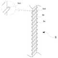
도 1은 본 발명의 엠보 형상을 갖는 시술용 실을 도시한 사시 도면,
도 2는 도 1의 평면도,
도 3은 본 발명의 엠보 형상을 갖는 시술용 실을 제조하기 위한 제조장치를 도시한 사시 도면,
도 4는 본 발명의 도 3에 표기된 "A" 부분을 확대하여 도시한 사시 도면,
도 5는 본 발명의 도 3에 표시된 "B"의 부분을 확대하여 도시한 사시 도면,
도 6은 본 발명의 도 3에 도시된 장력조절부(부호 40)의 부분을 확대하여 도시한 사시 도면,
도 7은 본 발명의 도 4에 도시된 헬리컬기어(부호,HG) 및 안내롤러 사이로 개재된 실의 압박 상태를 도시한 측면 도면이다.
도 8은 본 발명의 엠보 형상을 갖는 시술용 실의 제1 변형 형태 도면,
도 9는 본 발명의 엠보 형상을 갖는 시술용 실의 제2 변형 형태 도면,
도 10은 본 발명의 엠보 형상을 갖는 시술용 실의 제3 변형 형태 도면이다.
도 11은 도 1의 실에 대한 치형부 배열 형태를 도시하고 있는 도 2의 치형부 배열 형태와 다른 배열 형태를 도시한 평면도이다.1 is a perspective view showing a procedure room having an embossed shape according to the present invention,
Fig. 2 is a plan view of Fig. 1,
Fig. 3 is a perspective view showing a manufacturing apparatus for manufacturing a procedure room having an embossed shape according to the present invention,
Fig. 4 is a perspective view showing an enlarged view of the portion "A" shown in Fig. 3 of the present invention,
Fig. 5 is a perspective view showing an enlarged portion of the portion "B" shown in Fig. 3 of the present invention,
6 is an enlarged perspective view of a portion of the
Fig. 7 is a side view showing the helical gear (reference symbol HG) shown in Fig. 4 of the present invention and the pressing state of the yarn interposed between the guide rollers; Fig.
Fig. 8 is a first modification of the embodying chamber having an embossed shape according to the present invention,
Fig. 9 is a second modification of the embodying chamber having an embossed shape according to the present invention,
10 is a view showing a third modified form of the practicing chamber having the embossed shape of the present invention.
11 is a plan view showing an arrangement different from that of the tooth arrangement of FIG. 2 showing the tooth arrangement arrangement for the chamber of FIG.
본 발명에 있어 첨부된 도면은 설명의 명료성과 편의를 위해 과장되어 도시됨을 밝히고, 후술되는 실시 예는 본 발명의 권리범위를 한정하는 것이 아니라 본 발명의 청구범위에 제시된 구성요소의 예시적 사항에 불과하며, 다른 여러 형태로 변형 실시되는 점까지 감안한 명세서 전반에 걸친 기술적 사상을 토대로 해석되어야 한다.It is to be understood that both the foregoing general description and the following detailed description are exemplary and explanatory and are intended to provide further explanation of the invention as claimed. And it should be interpreted based on the technical ideas throughout the specification taking into consideration that various modifications are made.
아울러, 하기 본 발명에서는 실시 예로 한정되는 것이 아니라, 명세서 전반에 기재된 기술적 내용을 토대로 해석한 확장 범위까지 포함하는 권리범위로 인정되어야만 할 것이다.In addition, the present invention should not be construed as being limited to the embodiments described below, but should be construed as a scope of scope including an extended scope interpreted based on the technical content described in the specification.
이하, 본 발명에 따른 엠보 형상을 갖는 시술용 실 및 제조방법은 바람직한 실시 예로 첨부된 도면들과 함께 상세히 설명된다.DESCRIPTION OF THE PREFERRED EMBODIMENTS Hereinafter, an embroidery chamber and a manufacturing method according to the present invention will be described in detail with reference to the accompanying drawings.
도 1 및 도 2에 도시된 바와 같이, 본 발명에 의한 시술용 실(S)은 길이 방향으로 일정한 간극을 유지하며 다수의 철부(凸部, Sa) 형태를 형성하고, 상기 철부들의 각 사이로 다수의 요부(凹部, Sb) 형태를 형성하게 된다.As shown in FIGS. 1 and 2, the treatment chamber S according to the present invention maintains a constant gap in the longitudinal direction and forms a plurality of convex portions Sa, and a plurality of Thereby forming a concave portion Sb.
이들 철부(Sa) 및 요부(Sb)들은 실(S)의 길이 방향을 따라 경사진 형태를 유지하게 되는데, 이처럼 경사 형태를 유지하는 철부(Sa) 및 요부(Sb) 형상의 실(S)을 피부 처짐이나 주름진 시술 환자 피부 속에 자입할 경우, 실(S)에 형성된 상기 철부(Sa) 및 요부(Sb)들로 인하여 피부를 강하게 리프팅 시킬 수 있다.The convex portion Sa and the concave portion Sb are inclined along the longitudinal direction of the thread S. The convex portion Sa and the concave portion S, The skin can be strongly lifted due to the convex portion Sa and the concave portions Sb formed in the thread S when the skin is slackened or wrinkled.
즉, 바늘과 함께 실(S)이 시술 환자 피부 속에 자입되면, 실(S)의 길이 방향으로 형성된 철부(Sa)는 피부 속의 세포층에서 걸림 형태를 유지하는 관계로 처진 피부를 강하게 리프팅 시키게 된다. 기존의 가시 형상 실은 가시가 실 길이 방향으로 수직의 가로지르는 형태를 가짐에 따라 리프팅 효과가 약한 단점이 있다.That is, when the thread S is inserted into the patient's skin together with the needle, the convex portion Sa formed in the longitudinal direction of the thread S strongly lifts the sagging skin due to the retaining shape in the cell layer in the skin. The conventional viscous yarn has a drawback that the lifting effect is weak due to the crossing of the vertical direction in the longitudinal direction of the yarn.
이처럼, 실(S)의 길이 방향을 따라 일정하게 형성된 다수의 철부(Sa) 및 요부(Sb)들은 기존 제품의 절삭 형태의 가시 형상 실이나 엠보 형상의 가시 형상 실과는 피부의 리프팅 정도를 비교하여 볼 때 상당한 차이를 나타내고 있다.As described above, the plurality of convex portions Sa and the concave portions Sb, which are formed uniformly along the longitudinal direction of the thread S, are compared with the visible thread of the cut shape of the conventional product or the degree of lifting of the skin from the embossed viscous thread Showing a considerable difference.
이러한 본 발명에 의한 시술용 실(S)은 길이를 따라 철부(Sa) 및 요부(Sb)를 형성함에 있어서, 종래의 실과 같은 절개 과정의 수행으로 가시 형상을 갖는 것이 아니라, 절개 과정 수행 없이 실(S) 자체에 압력을 행사하여 엠보 형상과 같은 도움 자국을 형성하되, 실(S) 자체의 길이 방향을 따라 경사진 형태의 철부(Sa) 및 요부(Sb)로 구성된 치형부(Sa,Sb)를 형성하게 되는데, 이러한 치형부(Sa,Sb)가 피부 속에서 강한 걸림 작용을 수행하게 되면서 피부의 강한 리프팅 효과를 나타낼 수 있게 된다.The surgical chamber S according to the present invention is not limited to a viscous shape by performing a cutting process such as a conventional thread in forming the convex portion Sa and the concave portion Sb along the length, (Sa, Sb) composed of a convex portion (Sa) and a concave portion (Sb) inclined in the longitudinal direction of the seal (S) itself by forming a helper station such as an embossed shape by exerting pressure on the concave portion The teeth Sa and Sb perform a strong jigging action in the skin, and thus can exhibit a strong lifting effect of the skin.
따라서, 본 발명의 시술용 실(S)을 길이 방향을 따라 엠보 형상의 철부 및 요부들을 형성하는 관계로, 종래의 가시 형상에 요구되는 실의 절개 과정이 필요 없고, 강한 리프팅에 의해 실의 절개 부위가 완전히 갈라져 실이 떨어지거나 분리되는 문제도 방지하는 특징을 지니게 된다.Therefore, since the embroidery chamber S of the present invention forms embossed convex portions and concave portions along the longitudinal direction, there is no need for a thread cutting process required for a conventional visible shape, And also prevents the problem that the yarn is completely separated and separated from the yarn.
물론, 이때, 헬리컬 기어에 의해 실(S) 길이에 따라 형성된 치형부(Sa,Sb)들을 기준으로 시술의 사용 목적이나 시술받는 자의 피부 상태를 고려하여 소정의 공정을 더 부가하여 다양한 변형 형태로도 형성될 수 있는 특징까지 가능하다.Of course, at this time, a predetermined process may be further added in consideration of the use purpose of the procedure or the skin condition of the recipient on the basis of the teeth Sa and Sb formed according to the length of the thread S by the helical gear, It is possible to have a feature that can be formed.
이러한 치형부의 다양한 변형은 도 8 내지 도 10에 도시된 도면을 참조할 수 있는바, 도 8의 경우 상술된 헬리컬 기어의 기준이 되는 치형부(Sa,Sb)에 있어서 철부(Sa)의 끝단이 경사진 방향보다 더욱 급격한 경사로 연장된 변형 형태(Sa1)를 가짐에 따라, 상술된 헬리컬 기어의 기준이 되는 치형부(Sa,Sb) 보다 더욱 강한 피부 속 걸림이 이루어져 더욱 강한 피부 리프팅을 구현시킬 수 있다.8 to 10, the tip of the convex portion Sa of the teeth Sa and Sb, which is a reference of the helical gear described above in FIG. 8, Since the deformation shape Sa1 extending at a steeper slope than the tilted direction is provided, stronger skin fastening is achieved than the teeth Sa and Sb which are the reference of the above-mentioned helical gear, have.
또한, 도 9의 경우 상술된 헬리컬 기어의 기준이 되는 치형부(Sa,Sb)에 있어서 철부(Sa)의 끝단 일부를 모따기 하는 변형 형태(Sa2)를 가짐에 따라, 상술된 헬리컬 기어의 기준이 되는 치형부(Sa,Sb) 보다 더욱 약한 피부 속 걸림이 이루어져 더욱 약한 피부 리프팅을 구현시킬 수 있다.In the case of Fig. 9, since the helical gears Sa and Sb serving as the reference of the above-described helical gear have the deformed shape Sa2 in which a part of the end of the convex portion Sa is chamfered, The skin is caught more weakly than the toothed portions Sa and Sb, so that a weaker skin lifting can be realized.
아울러, 도 10의 경우 상술된 헬리컬 기어의 기준이 되는 치형부(Sa,Sb)에 있어서 철부(Sa)의 끝단에 대한 높이 차를 두는 방식으로 모따기 하는 변형 형태(Sa3)을 가짐에 따라, 상술된 헬리컬 기어의 기준이 되는 치형부(Sa,Sb)에 비해 피부 속 걸림이 다단 걸림인 이중 걸림으로 구현시켜 걸림의 안전성을 확보시킬 수 있다.In addition, in the case of Fig. 10, since the teeth Sa and Sb serving as the reference of the above-described helical gear have the deformed shape Sa3 which is chamfered in such a manner that the height difference with respect to the end of the convex portion Sa is set, Which is a reference of a helical gear, Sa and Sb, can be secured by double-locking the multi-step engagement of the skin.
이처럼, 헬리컬 기어의 기준이 되는 치형부(Sa,Sb)들을 갖는 실(S)을 기준으로 치형부(Sa,Sb)들에 대한 끝단의 변형 형태(Sa1,Sa2,Sa3)를 다양하게 둠에 따라, 시술받는 자는 시술자와 상의하여 자신의 피부 상태에 맞는 실(S)을 고를 수 있으며, 이와 같이 선택된 실(S)을 이용하여 시술받음에 따라 시술의 부작용도 최소화시킬 수 있는 이점이 있다.As described above, the deformed shapes Sa1, Sa2 and Sa3 of the end portions with respect to the teeth Sa and Sb are variously defined on the basis of the thread S having the teeth Sa and Sb serving as the reference of the helical gear Accordingly, the recipient can consult the practitioner to select a thread S that matches his or her skin condition, and the side effect of the procedure can be minimized as the procedure S is performed using the selected thread S as described above.
한편, 도 2에 도시된 바와 같이 치형부(Sa,Sb)의 배열에 있어서 실(S)의 길이 방향을 따라 모두 경사진 형태들로만 형성되는 순배열 타입일 수도 있고, 또한 도 11에 도시된 바와 같이 실(S)의 길이 방향을 따라 경사진 형태와 수직 형태가 번갈아 교대하며 형성되는 조합배열 타입일 수도 있다.Alternatively, as shown in Fig. 2, it may be of a purely arranged type which is formed only in inclined shapes along the longitudinal direction of the thread S in the arrangement of the teeth Sa and Sb, A combination arrangement type in which the inclined shape and the vertical shape are alternately formed alternately along the length direction of the thread S may be used.
특히, 치형부(Sa,Sb)의 배열이 경사와 수직 형태의 조합배열 타입일 경우, 피부 속에서 양 방향으로의 걸림 과정에서 치형부의 경사진 배열 구간에서 쏠림 방식의 걸림 문제를 치형부의 수직 배열 구간이 해소하는 역할을 수행하여 전체적인 걸림 방향의 안정화를 도모할 수 있다.Particularly, when the arrangement of the teeth Sa and Sb is a combined arrangement type of a slant and a vertical shape, the problem of the stuck-at-once engagement in the inclined arrangement region of the teeth during the engagement in both directions in the skin, So that the entire engagement direction can be stabilized.
예를 들어, 피부 속에서 실(S)의 걸림이 일측 방향으로 작용될 경우에 치형부의 경사 배열 구간에서는 치형부(Sa,Sb)의 양단부 중 일측 단부에서만이 걸림되는 쏠림 방식의 걸림 문제가 발생하게 되는데, 이때, 치형부(Sa,Sb)의 수직 배열 구간의 치형부(Sa,Sb) 양단부가 쏠림 걸림 현상을 줄여 줌에 따라 실(S) 전체의 걸림 방향에 대한 안정화가 이루어질 수 있다. 물론, 피부 속에서 실(S)의 걸림이 타측 방향으로 작용될 경우에도 상기와 같은 동일한 이유로 쏠림 방식의 걸림 문제를 줄일 수 있다.
For example, in the case where the engagement of the thread S in the skin is performed in one direction, there is a problem in that the thread is caught in only one end portion of both ends of the teeth Sa and Sb in the inclined array portion of the teeth At this time, both ends of the teeth Sa and Sb of the vertically arranged sections of the teeth Sa and Sb can be stabilized with respect to the direction in which the entire thread S is hooked as the threading engagement phenomenon is reduced. Of course, even if the engagement of the thread S in the skin is applied in the other direction, it is possible to reduce the engagement problem of the tilting method for the same reason as described above.
이와 같은 본 발명의 엠보 형상의 시술용 실(S)에 대한 제조방법이 후술된다.A manufacturing method for the embossed treatment chamber S of the present invention is described below.
본 발명에 의한 엠보 형상의 실(S) 제조방법은, 도 3 내지 도 7의 장치 도면들을 참고로 하되, 실의 세팅 단계, 장치 구동 단계, 실의 감김 및 풀림 단계, 실의 엠보 형성 단계, 실의 감김 완료 단계를 포함하게 된다.The method for manufacturing embossed yarn S according to the present invention will now be described with reference to the apparatus drawings of Figs. 3 to 7, including the steps of setting the yarn, driving the device, winding and unwinding the yarn, And a thread winding completion step.
a. 실의 세팅 단계a. Setting the Thread
실의 세팅 단계는, 실을 장치의 동작 이전에 알맞게 세팅하는 단계로서, 감긴 실의 장착 단계, 및 감긴 실의 풀림 단계를 포함하며, 상기 감긴 실의 장착 단계는 장치 일측 편에 구비된 풀림부(10)의 각 풀림롤러(UR1,UR2,UR3)에 감긴 실(S)을 삽입하여 걸 수 있도록 하는 과정이며, 상기 감긴 실의 풀림 단계는 상기 각 풀림롤러(UR1,UR2,UR3)에 감긴 실(S)들을 소정의 길이만큼 풀어 장치 타측 편에 구비된 감김부(60)의 각 감김롤러(WR1,WR2,WR3)에 고정하도록 하는 과정이다.The setting step of the thread includes a step of setting the thread before the operation of the apparatus and including a step of mounting the wound thread and a step of unwinding the wound thread, (UR1, UR2, UR3) of the winding rollers (UR1, UR2, UR3) of the winding rollers (10) The yarns S are loosened by a predetermined length and secured to the respective winding rollers WR1, WR2 and WR3 of the
물론, 이때 본 발명에 의한 실(S)은 상기 풀림부(10)와 상기 감김부(60) 사이 구간에 구축되는 분기부(20), 엠보가공부(30), 장력조절부(40), 감김방향조절부(50)에도 적절히 세팅된다.The yarn S according to the present invention may include a branched
즉, 상기 분기부(20)에서는 실(S)이 분기롤러(23)에 형성된 각각의 분기홈(23a,23b,23c)으로 분기되도록 하는 과정으로서 기둥 플레이트(21)에 상측에 수직으로 배열된 수직핀(22)들 사이로 실(S)의 분기 작업을 수행하게 된다.That is, in the branching
상기 엠보가공부(30)에서는 실(S)이 헬리컬기어(HG)와 안내롤러(32) 사이로 각각의 분기된 실(S)들을 개재하는 작업을 수행하게 된다.In the
상기 장력조절부(40)에서는 실(S)의 굵기에 따라 실(S)의 장력을 조절하는 과정으로 장력조절대(43)의 회전 각을 조정하여 실(S) 장력을 조절할 수 있다.The
상기 감김방향조절부(50)에서는 실(S)이 상기의 감김부(60)에 고르게 감길 수 있도록 감김방향조절블럭(54)을 좌우 편으로 조절 이동하는 과정이다.
In the winding direction adjusting unit 50, the winding
b. 장치 구동 단계,b. Device driving step,
장치 구동 단계는 장치에 구성된 구성부들에 대한 작동을 인가하는 과정으로서, 엠보가공부(30)의 모터(M), 감김방향조절부(50)의 구동모터(53), 감김부(60)의 구동모터(62)에 대한 구동을 인가하게 된다.
The device driving step is a step of applying the operation to the constituent units configured in the apparatus and includes a step of controlling the motor M of the
c. 실의 감김 및 풀림 단계c. Step of unwinding and loosening thread
장치의 일측 편에 구축된 풀림부(10)의 각 풀림롤러(UR1,UR2,UR3)들은 타측 편에 구축된 감김부(60)의 각 감김롤러(WR1,WR2,WR3)의 회전력에 의해 실(S)이 당겨지면서 풀리고, 상기 감김부(60)의 각 감김롤러(WR1,WR2,WR3)에 실(S)이 감겨지는 과정이 시작된다. 물론, 이때 감김부(60)의 각 감김롤러(WR1,WR2,WR3)는 모터(62) 구동에 의해 회전력을 얻게 된다.
Each of the unloading rollers UR1, UR2 and UR3 of the unloading
d. 실의 엠보 형성 단계d. Embo forming step of thread
장치의 상기 풀림부(10) 후방에 구축된 엠보가공부(30)의 헬리컬기어(HG)와 안내롤러(32) 사이로 실(S)이 투입되면서 상기 헬리컬기어(HG)의 기어이 압박에 의해, 투입 진행되는 실(S)의 표면이 압력을 받게 됨에 따라, 실(S) 표면에 치형부(Sa,Sb) 자국을 형성하게 된다.
The thread S is inserted between the helical gear HG and the
f. 실의 감김 완료 단계f. Step of wrapping thread
장치의 타측 편에 구축된 감김부(60)의 각 감김롤러(WR1,WR2,WR3)에 치형부(Sa,Sb) 자국을 형성한 실(S)이 각각 감기어지면서 상기 장치의 일측 편에 구축된 풀림부(10)의 각 풀림롤러(UR1,UR2,UR3)로부터 실(S)의 풀림 종료에 이은 상기 각 감김롤러(WR1,WR2,WR3)의 실(S) 감김이 완료된다.
The yarns S forming the marks of the teeth Sa and Sb are wound on the respective take-up rollers WR1, WR2 and WR3 of the
한편, 본 발명의 엠보 형상을 갖는 실(S)을 제조하기 위한 제조장치는 도 3 내지 도 7을 참고로 하기에서 상세히 설명된다.On the other hand, a manufacturing apparatus for manufacturing the embossed yarn S of the present invention will be described in detail below with reference to Figs. 3 to 7.
지지판(SB)을 기준으로 일측 편에는 풀림부(10)가 타측 편에는 감김부(60)가 구축되고, 상기 풀림부(10) 및 감김부(60)의 사이 구간에는 순차적으로 분기부(20), 엠보가공부(30), 장력조절부(40), 및 감김방향조절부(50)로 구축된다.A
상기 풀림부(10)는 지지판(SB)에 기립된 형태로 설치된 사이드 플레이트(11)에 다수의 제1,2,3 풀림롤러(UR1,UR2,UR3)들이 일정한 간극으로 설치되는바, 이러한 풀림롤러(UR)들은 개수의 증감이 가능하다.The unloading
상기 감김부(60) 역시 지지판(SB)에 기립된 형태로 설치된 사이드 플레이트(61)에 상기 제1,2,3 풀림롤러(UR1,UR2,UR3)와 대응될 수 있는 제1,2,3 감김롤러(WR1,WR2,WR3)들이 일정한 간극으로 설치되며 개수의 증감도 가능하다. 아울러 상기 제1,2,3 감김롤러(WR1,WR2,WR3)들은 개별적으로 회전 가능하도록 개별 구동모터(62)에 의해 회전될 수 있다.The
상기 분기부(20)는 풀림부(10)의 후방에 구축되는 구성품으로서, 기둥 플레이트(21) 상에 수직으로 설치된 다수의 수직핀(22)들과, 상기 수직핀들의 후방으로 단품의 분기롤러(23)가 힌지 상태로 설치된다.The branching
상기 다수의 수직핀(22)들은 각각 일정한 간극을 유지하며 수직 설치되는데, 수직핀(22) 각각에 일정한 간극을 두는 이유는 실(S)의 분기를 위함이며, 단품의 분기롤러(23) 표면에 일정한 간극으로 다수의 분기홈(23a,23b,23c)들을 형성하는 이유는 분기된 실(S)들을 각각 안내하기 위함이다.The plurality of
한편, 상기 엠보가공부(30)는 분기부(20)의 후방에 구축되는 구성품으로서, 받침 플레이트(31) 상에 설치되는 모터(M)와, 상기 모터(M)의 축에 연결되는 헬리컬기어(HG)와, 상기 헬리컬기어(HG)의 하측에서 받침 플레이트(31) 측면에 설치되는 안내롤러(32)를 포함한다.The
상기 헬리컬기어(HG)는 그 기어이가 도면 4에서 이중으로 도시되었지만, 삼중 또는 사중이나 싱글로 증감될 수 있다. 상기 헬리컬기어(HG)의 하측에 위치된 안내롤러(32)의 표면에는 일정한 간극을 유지하며 각각의 안내로(32a,32b,32c)들을 형성하고 있다. 이러한 안내로 역시 안내롤러(32)의 표면에 증감이 가능하다.The helical gear HG is double geared in FIG. 4, but can be increased or decreased in triple, quadrature or single. 32b and 32c are formed on the surface of the
상기 헬리컬기어(HG)의 각 기어이들은 안내롤러(32)의 각 안내로(32a,32b,32c)에 일부 수용되는 형태로 회전되는데, 이처럼 헬리컬기어(HG)의 기어이와 안내로 사이로 실(S)이 투입되면서 지나감에 따라 실(S) 표면이 헬리컬기어(HG)의 기어이 가압을 받게 되는 방식이다.Each gear of the helical gear HG is rotated in such a manner that it is partly accommodated in each of the
한편, 상기 장력조절부(40)는 상기 엠보가공부(30)의 후방에 구축되는 구성품으로서, 기둥 플레이트(41)의 측면에 축설되는 장력조절대(43)를 구성하게 되는데, 이러한 장력조절대(43)는 다수의 대(43a,43b,43c)와 상기 대(43a,43b,43c) 사이로 형성된 간극(G1,G2) 및 대(43a,43b,43c)의 후미에서 직각으로 절곡 돌출된 돌출지(43d)로 구성되며, 전방으로 다수의 분기홈(44a,44b,44c)들을 형성한 장력조절롤러(44)가 힌지 연결되고, 대(43a,43b,43c)의 측면 후미에 각각 고정되는 분기고리(QG1,QG2,QG3)들로 구성된다.The
상기 장력조절대(43)는 기둥 플레이트(41)의 측면에 그 후미가 축설되어 회전될 수 있도록 상기 각 돌출지(43d)에 축설된 축봉(42)에 결합되어 회전 반경을 조절하며 실(S)의 장력 조절이 가능하게 된다.The
한편, 상기 감김방향조절부(50)는 상기 장력조절부(40)의 후방에 구축되는 구성품으로서, 좌우의 측벽블럭(51,52)에 설치된 레일(RL)에 물려 좌우 슬라이드 이동하는 감김방향조절블럭(54)을 구성하게 되는데, 이러한 감김방향조절블럭(54)은 그 중앙에 중공(H)을 형성하여 좌우 측벽블럭(51,52) 사이로 축설된 축봉(53a)이 관통될 수 있으며, 그 상부 후미에 일정 간격으로 다수의 고리(54a,54b,54c)들을 포함하게 된다.The winding direction adjusting unit 50 is constructed as a component behind the
상기 고리(54a,54b,54c)들은 분기된 실(S)들을 각각 관통시키기 위한 것으로 실(S)의 분기 상태를 유지하도록 하기 위함이다.The
물론, 상기 감김방향조절블럭(54)은 좌우 측벽블럭(51,52) 중 어느 하나의 블럭 타측에 구성된 구동모터(62)의 동력에 의해 회전되는 축봉(53a) 회전에 의해 좌우로 슬라이드 이동되며 분기된 실(S)의 감김을 고르게 한다.
Of course, the winding
하기에서 본 발명의 제조장치에 대한 작용 관계를 설명하기로 한다.Hereinafter, the functional relationship with the production apparatus of the present invention will be described.
감김부(60)의 각 감김롤러(WR1,WR2,WR3)가 개별 구동모터(62)에 의해 회전되면서 이러한 회전력에 의해 풀림부(10)의 각 풀림롤러(UR1,UR2,UR3)가 회전되며 실(S)들이 풀린다.The respective winding rollers WR1, WR2 and WR3 of the
풀림 상태의 실(S)들은 감김부(60)의 각 감김롤러(WR1,WR2,WR3)에 감기어지기 전에 분기부(20)의 수직핀(22)들 사이로 분기되고, 이렇게 분기된 실(S)들은 수직핀(22)들의 후방에 위치된 분기롤러(23)의 각 분기홈(23a,23b,23c)들의 안내를 받으며 이송된다.The loosened threads S are split between the
곧, 엠보가공부(30)의 헬리컬기어(HG)의 기어이 및 안내롤러(32)의 각 안내로(32a,32b,32c) 사이로 진입되는 개별 분기 실(S)들은 회전되는 헬리컬기어(HG)의 기어이 압입에 의해 요철(Sa,Sb)형의 엠보 형상을 얻게 된다.Namely, the individual branching chambers S, which enter between the gears of the helical gear HG of the
상기 헬리컬기어(HG)는 모터(M) 구동에 의해 축 회전으로 회전되며, 상기 안내롤러(32)의 연동도 가능하고, 멈춤 상태를 유지하여도 무방하다.The helical gear HG is rotated by the rotation of the shaft by the drive of the motor M, and the
요철형의 엠보 형상을 가진 개별 분기 실(S)들은 곧 장력조절부(40)에 진입하게 되는데, 실의 굵기에 따라 장력조절부(40)의 장력조절대(43) 회전 조절로 실의 장력 조절이 가능하다.The individual branching chambers S having the embossed embossed shape immediately enter the
즉, 개별 분기 실(S)들은 장력조절대(43)의 선방인 전방에 힌지 연결된 장력조절롤러(44)의 분기홈(44a,44b,44c)들을 따라 이동되다가 장력조절대(43)의 후미에 각각 고정된 분기고리(QG1,QG2,QG3)를 관통하게 된다. 상기 분기고리(QG1,QG2,QG3)는 개별 실(S)들에 대한 분기 상태가 유지되도록 하는 역할을 수행한다.That is, the individual branch chambers S are moved along the
축봉(42)과 함께 회전되는 장력조절대(43)는 회전 반경에 따라, 풀림부(10)에서부터 감김부(60)에 이르기까지 풀려진 실(S)들의 절곡 부위를 조절하여 실(S)의 장력을 조정하게 된다.The
예를 들어, 도면상에서 장력조절대(43)가 시계 방향으로 회전하게 되면 실(S)의 이동 경로 위치가 높아짐에 따라, 실의 절곡 부위가 대부분 사라지면서 곡률의 완만함을 이루기 때문에 실의 장력이 약화될 수 있는 반면, 장력조절대(43)가 반시계 방향으로 회전하게 되면 실(S)의 이동 경로 위치가 낮아짐에 따라, 실의 절곡 부위가 많이 발생되면서 곡률의 급격함을 이루기 때문에 실의 장력이 강화될 수 있다. 즉, 실의 굵기에 따라 장력조절대(43)의 회전 반경을 달리하면서 실에 대한 장력 조절이 가능하게 된다.For example, when the
곧, 감김방향조절부(50)로 진입되는 개별 실(S)들은 감김방향조절블럭(54)의 상부에 고정된 다수의 고리(54a,54b,54c)들을 관통하며 이동되는데, 이 과정에서 감김방향조절블럭(54)은 구동모터(53)의 구동에 의해 회전되는 축봉(53a) 회전에 의해 레일(RL)에 물린 채 좌우 슬라이드 하게 된다.The individual chambers S which enter the winding direction adjusting part 50 are moved through the plurality of
즉, 축봉(53a)은 나사 형상으로 이루어져 축봉(53a)의 정 역 회전에 따라 감김방향조절블럭(54)이 좌 또는 우 방향으로 슬라이드 진행될 수 있다.That is, the
이러한 감김방향조절블럭(54)의 좌 또는 우 방향 슬라이드 이동으로 고리(54a,54b,54c)들을 관통한 개별 실(S)들은 감김부(60)의 각 감김롤러(WR1,WR2,WR3)에 감기는 실(S)들의 고른 감김을 조절할 수 있게 된다. 예를 들어 상기 감김방향조절블럭(54)이 좌 또는 우 방향으로 슬라이드 이동하지 않을 경우, 감김롤러(WR1,WR2,WR3)에 감기는 실들이 한쪽으로 치우친 상태로 감겨져 감김의 고른 상태를 유지할 수 없게 된다. 즉, 감김의 고른 정렬을 위해 감김방향조절블럭(54)의 좌우 이동이 필요하다.The individual chambers S passing through the
SB: 지지판, S: 실
10: 풀림부,11: 사이드 플레이트
UR1,UR2,UR3: 풀림롤러
20: 분기부,22: 수직핀,
23: 분기롤러, 23a,23b,23c: 분기홈
30: 엠보가공부, HG: 헬리컬기어
32: 안내롤러, 32a,32b,32c: 안내로
40: 장력조절부42: 축봉,
43: 장력조절대, 43a,43b,43c: 대
43d: 돌출지
44: 장력조절롤러, 44a,44b,44c: 분기홈
QG1,QG2,QG3: 분기고리,
50: 감김방향조절부53a: 축봉
RL: 레일,54: 감김방향조절블럭,
54a,54b,54c: 고리
60: 감김부,WR1,WR2,WR3: 감김롤러SB: support plate, S: room
10: unloading portion, 11: side plate
UR1, UR2, UR3: Release roller
20: branch portion, 22: vertical pin,
23: branching roller, 23a, 23b, 23c: branching groove
30: embroidering, HG: helical gear
32: guide roller, 32a, 32b, 32c:
40: tension adjusting part 42: shaft rod,
43: tension adjusting table, 43a, 43b, 43c:
43d:
44: tension adjusting roller, 44a, 44b, 44c:
QG1, QG2, QG3: branch ring,
50: Winding
RL: Rail, 54: Winding direction adjusting block,
54a, 54b, 54c:
60: spool part, WR1, WR2, WR3: take-up roller
Claims (12)
Translated fromKorean장치에 구성된 상기 구성품들의 구동을 인가하는 장치 구동 단계;
상기 구성품들 중 감김부를 통하여 실의 감김이 시작되고, 풀림부를 통하여 실의 풀림이 시작되는 실의 감김 및 풀림단계;
상기 구성품들 중 엠보가공부를 통하여 실의 표면에 요철형의 엠보를 형성하는 실의 엠보 형성 단계;
상기 구성품들 중 상기 풀림부로부터 풀리는 실의 풀림 종료에 이은 상기 감김부로부터 감기는 실의 감김이 완료되는 실의 감김 완료 단계;
를 포함하여 구성되는 것을 특징으로 하는 엠보 형상의 시술용 실 제조방법.A thread setting step of setting the yarn before the driving of the apparatus to suit the components of the unwinding part, the branching part, the embossing part, the tension adjusting part, the winding direction adjusting part, and the winding part;
A device driving step of applying driving of the components configured in the device;
Winding and unwinding the yarn in which winding of the yarn is started through the winding portion of the components and winding of the yarn is started through the unwinding portion;
An embossing step of a yarn forming a concave-convex emboss on the surface of the yarn through the embossing of the components;
A winding completion step of winding the yarn wound from the winding part after winding of the yarn to be unwound from the unwinding part is completed;
The method of claim 1, further comprising:
상기 실의 세팅 단계는, 상기 풀림부의 각 풀림롤러에 감긴 실을 삽입하여 걸게 하는 감긴 실의 장착 단계;
상기 각 풀림롤러에 감긴 실들을 소정의 길이만큼 풀어 상기 감김부의 각 감김롤러에 고정하는 감긴 실의 풀림 단계;
를 더 포함하여 구성되는 것을 특징으로 하는 엠보 형상의 시술용 실 제조방법.5. The method of claim 4,
Wherein the setting of the thread includes a step of inserting and winding a thread wound on each of the release rollers of the unloading portion;
A winding step of loosening the yarns wound on the respective unwinding rollers by a predetermined length and fixing them to the respective winding rollers of the winding unit;
Wherein the embossing method further comprises the steps of:
분기부의 수직핀들 사이로 실을 분기하고;
엠보가공부의 헬리컬기어 및 안내롤러 사이로 각 분기된 실들을 투입 개재하며;
실의 굵기에 따라 장력조절부의 장력조절대 회전 각을 조정하여 실의 장력을 조절하고;
감김부의 각 감김롤러에 분기된 실들이 고르게 감김 수 있도록 감김방향조절블럭을 조절하는 과정이 더 수행되는 것을 특징으로 하는 엠보 형상의 시술용 실 제조방법.The method according to claim 4 or 5,
Branching the yarn between the vertical fins of the bifurcation;
The embossed yarns are inserted and interposed between the helical gears of the work and the guide rollers;
Adjust the tension of the yarn tensioner by adjusting the rotation angle of the tensioner of the tensioner according to the thickness of the yarn;
Wherein the step of adjusting the winding direction adjusting block is performed so that the yarns branching to the respective winding rollers of the winding part can be evenly wound.
상기 풀림부와 상기 엠보가공부 사이 구간에는 풀림부에 다수로 장착된 실타래를 여러 가닥으로 분기하는 분기부;
상기 엠보가공부와 상기 감김부 사이 구간에 실의 굵기에 따라 장력을 조절하는 장력조절부; 및
상기 감김부에 감기는 실의 고른 감김을 위해 지지판의 좌우편으로 이동하며 실의 감김 방향을 조절하는 감김방향조절부;
를 더 포함하여 구성되는 것을 특징으로 하는 엠보 형상의 시술용 실 제조장치.A loosening portion which is formed on one side of the support plate and is wound in a state without embossing, the loosening portion being inserted and fastened more than one time, A spiral winding part wound around the embossed yarns wound on the other side with respect to the support plate and being unwound from the unwinding part; And an embossment construction constructed in a section between the unloading portion and the winding portion to press the chambers to be unloaded from the unloading portion to apply an embossing embossing shape; Lt; / RTI >
A branching portion for branching the plurality of threads mounted on the unloading portion into a plurality of strands in a section between the unloading portion and the embossing portion;
A tension regulating unit for regulating the tension in accordance with the thickness of the yarn between the emboss work and the winding unit; And
A winding direction adjusting unit moving to the left and right sides of the support plate to adjust the winding direction of the yarn for even winding of the yarn wound on the winding unit;
And an embossing step of attaching the embossing unit to the processing chamber.
상기 풀림부 및 상기 감김부는, 지지판에 기립된 사이드 플레이트의 측면에 다수개로 설치된 풀림롤러 및 감김롤러로 구성되는 한편, 상기 감김롤러는 구동모터 회전에 의해 회전되는 것을 특징으로 하는 엠보 형상의 시술용 실 제조장치.9. The method of claim 8,
Wherein the unwinding portion and the winding portion are constituted by a release roller and a take-up roller provided on a side surface of the side plate rising on the support plate, and the take-up roller is rotated by the rotation of the drive motor (2).
상기 엠보가공부는,
받침 플레이트 상에 모터와 함께 설치되어 모터 구동에 의해 회전되면서 지나가는 실을 가압하여 실 표면에 요철형의 엠보 형상을 가하는 헬리컬기어;
상기 헬리컬기어의 하측에서 받침 플레이트의 측면에 설치되어 상기 헬리컬기어의 기어이 일부를 수용하는 한편 분기된 실의 이송로가 되는 다수의 분기홈을 형성한 안내롤러;
를 포함하는 것을 특징으로 하는 엠보 형상의 시술용 실 제조장치.9. The method of claim 8,
In the emboss work,
A helical gear which is installed on the support plate together with the motor and presses the passing thread while being rotated by the motor driving to apply a concave-convex emboss shape to the seal surface;
A guide roller provided on a side of the receiving plate at a lower side of the helical gear to receive a part of the gear of the helical gear and to form a plurality of branched grooves as a conveying path of the branched chamber;
And an embossing step of disposing the embroidery yarn on the embroidery yarn.
상기 분기부는, 기둥 플레이트 상에서 일정 간극을 유지하며 수직으로 설치되어 실들을 분기하는 다수의 수직핀;
상기 수직핀의 후방에서 기둥 플레이트 상에 힌지 연결되어 수직핀들의 사이를 관통한 분기 실들을 각각 분기하는 다수의 분기홈들을 형성한 분기롤러를 더 포함하고,
상기 장력조절부는, 기둥 플레이트의 측면에 후미가 축설되어 회전 반경을 조절하게 되는 여러 대와 간극으로 구성된 장력조절대;
상기 장력조절대의 전방에 힌지 상태로 연결되어 분기 상태의 실들을 분기하며 실의 장력을 조절하는 다수의 분기홈들을 형성한 장력조절롤러;
상기 장력조절대의 측면 후미에 고정되어 분기 상태의 실들을 각각 관통시키는 다수의 분기고리를 더 포함하는 것을 특징으로 하는 엠보 형상의 시술용 실 제조장치.9. The method of claim 8,
The bifurcated portion includes a plurality of vertical fins vertically installed to maintain a predetermined gap on the column plate and to divide the chambers;
Further comprising a branching roller formed in the rear of the vertical pin and having a plurality of branching grooves connected to the column plate by being hingedly connected to the branching chambers,
Wherein the tension adjuster includes a tension adjuster having a plurality of shafts and gaps for adjusting the radius of rotation of the shaft,
A tension regulating roller connected in a hinged state in front of the tension regulating block to form a plurality of branch grooves for branching the chambers in the branch state and controlling the tension of the yarn;
Further comprising a plurality of branch rings fixed to the lateral rear end of the tension adjusting bases to penetrate the chambers in the branched state, respectively.
상기 감김방향조절부는,
좌우 측벽블럭 사이로 설치되는 레일;
상기 레일에 물려 좌우 편으로 이동하며 실의 감김 방향을 조절하는 감김방향조절블럭;
상기 감김방향조절블럭 상에서 일정한 간격으로 수직 설치되어 분기된 상태의 실들을 각각 관통시키는 다수의 고리; 및
상기 감김방향조절블럭의 좌우 이동에 대한 동력을 제공하는 모터에 연결되어 좌우 측벽블럭 사이로 구축되며, 상기 감김방향조절블럭에 축설되어 모터 동력에 의해 회전하며 감김방향조절블럭의 좌우 이동을 유도하는 축봉;
을 더 포함하는 것을 특징으로 하는 엠보 형상의 시술용 실 제조장치.9. The method of claim 8,
The winding direction adjuster includes:
A rail installed between the left and right side wall blocks;
A winding direction adjusting block moving to the left and right sides by being caught by the rails and adjusting the winding direction of the yarn;
A plurality of rings vertically installed at predetermined intervals on the winding direction adjusting block to penetrate the yarns in the branched state, respectively; And
A winding shaft connected to the motor for providing power for the left and right movement of the winding direction adjusting block and being constructed between the left and right side wall blocks and rotating in the winding direction adjusting block to be driven by the motor power, ;
Further comprising: an embossing unit for attaching the embossing unit to the embossing unit.
Priority Applications (1)
| Application Number | Priority Date | Filing Date | Title |
|---|---|---|---|
| KR1020150043284AKR101692467B1 (en) | 2015-03-27 | 2015-03-27 | Surgical Suture And Manufacture Method And Apparatus Of That |
Applications Claiming Priority (1)
| Application Number | Priority Date | Filing Date | Title |
|---|---|---|---|
| KR1020150043284AKR101692467B1 (en) | 2015-03-27 | 2015-03-27 | Surgical Suture And Manufacture Method And Apparatus Of That |
Publications (2)
| Publication Number | Publication Date |
|---|---|
| KR20160115494A KR20160115494A (en) | 2016-10-06 |
| KR101692467B1true KR101692467B1 (en) | 2017-01-03 |
Family
ID=57164909
Family Applications (1)
| Application Number | Title | Priority Date | Filing Date |
|---|---|---|---|
| KR1020150043284AActiveKR101692467B1 (en) | 2015-03-27 | 2015-03-27 | Surgical Suture And Manufacture Method And Apparatus Of That |
Country Status (1)
| Country | Link |
|---|---|
| KR (1) | KR101692467B1 (en) |
Cited By (3)
| Publication number | Priority date | Publication date | Assignee | Title |
|---|---|---|---|---|
| KR102390262B1 (en)* | 2021-08-18 | 2022-04-25 | 주식회사 필코리아 | Cog Thread For Lifting |
| KR20220165492A (en)* | 2021-06-08 | 2022-12-15 | 주식회사 필코리아 | device of cog thread for skin surgery and cog thread manufactured therof |
| WO2023167381A1 (en)* | 2022-03-04 | 2023-09-07 | 주식회사 현대메디텍 | Apparatus and method for producing biodegradable thread and biodegradable thread produced using same |
Families Citing this family (1)
| Publication number | Priority date | Publication date | Assignee | Title |
|---|---|---|---|---|
| KR102711916B1 (en)* | 2022-07-12 | 2024-09-30 | 주식회사 엠베이스 | A method of processing the shape of a medical thread using a roller |
Citations (3)
| Publication number | Priority date | Publication date | Assignee | Title |
|---|---|---|---|---|
| KR101237481B1 (en)* | 2012-08-30 | 2013-02-26 | 백우인 | Medical surture with spiral protrusions |
| KR200468362Y1 (en)* | 2013-05-13 | 2013-08-09 | 강승훈 | Medical suture and manufacturing device for medical suture |
| KR101423712B1 (en)* | 2013-01-22 | 2014-08-01 | 홍유리 | Projection fiber of medicine for apotos and method of manufacturing of projection fiber of medicine for apotos |
Family Cites Families (5)
| Publication number | Priority date | Publication date | Assignee | Title |
|---|---|---|---|---|
| SG188784A1 (en) | 2008-04-15 | 2013-04-30 | Ethicon Llc | Self-retaining sutures with bi-directional retainers or uni-directional retainers |
| CA2797582C (en) | 2010-04-29 | 2018-04-10 | Ethicon, Llc | High-density self-retaining sutures, manufacturing equipment and methods |
| KR101200396B1 (en) | 2010-10-07 | 2012-11-12 | 주식회사 엠에이에스 | Pharmacothread for pharmacopuncture of Oriental medicine |
| KR101132841B1 (en) | 2011-03-07 | 2012-04-02 | 김영재 | A suture |
| KR20120117609A (en) | 2011-04-14 | 2012-10-24 | 김병건 | Fiber for operation and the operation device comprising the same |
- 2015
- 2015-03-27KRKR1020150043284Apatent/KR101692467B1/enactiveActive
Patent Citations (3)
| Publication number | Priority date | Publication date | Assignee | Title |
|---|---|---|---|---|
| KR101237481B1 (en)* | 2012-08-30 | 2013-02-26 | 백우인 | Medical surture with spiral protrusions |
| KR101423712B1 (en)* | 2013-01-22 | 2014-08-01 | 홍유리 | Projection fiber of medicine for apotos and method of manufacturing of projection fiber of medicine for apotos |
| KR200468362Y1 (en)* | 2013-05-13 | 2013-08-09 | 강승훈 | Medical suture and manufacturing device for medical suture |
Cited By (4)
| Publication number | Priority date | Publication date | Assignee | Title |
|---|---|---|---|---|
| KR20220165492A (en)* | 2021-06-08 | 2022-12-15 | 주식회사 필코리아 | device of cog thread for skin surgery and cog thread manufactured therof |
| KR102513561B1 (en) | 2021-06-08 | 2023-03-24 | 주식회사 필코리아 | device of cog thread for skin surgery and cog thread manufactured therof |
| KR102390262B1 (en)* | 2021-08-18 | 2022-04-25 | 주식회사 필코리아 | Cog Thread For Lifting |
| WO2023167381A1 (en)* | 2022-03-04 | 2023-09-07 | 주식회사 현대메디텍 | Apparatus and method for producing biodegradable thread and biodegradable thread produced using same |
Also Published As
| Publication number | Publication date |
|---|---|
| KR20160115494A (en) | 2016-10-06 |
Similar Documents
| Publication | Publication Date | Title |
|---|---|---|
| KR101692467B1 (en) | Surgical Suture And Manufacture Method And Apparatus Of That | |
| CN105745371B (en) | The projection forming apparatus and its method of operation line | |
| DE1660286C3 (en) | Method for cutting up strip or strand-like material, in particular for producing staple fibers, as well as device for carrying out the method | |
| CN113039061B (en) | System for cutting strip with helical cutter and corresponding cutting method | |
| DE102006021425A1 (en) | Separating and positioning device | |
| KR100880679B1 (en) | Special yarn manufacturing device for wrinkle removal | |
| JP2002227065A (en) | Continuous fabric take-down device for knitting machine | |
| FR2921858A1 (en) | APPLICATION HEAD FOR FIBER RIBBON | |
| KR101692693B1 (en) | apparatus of manufacturing surgical thread | |
| CN1932131A (en) | Apparatus for cutting and hemming of cloth articles and the like | |
| DE102009036053B4 (en) | Method and device for producing a batt with targeted fiber orientation | |
| KR102393380B1 (en) | Vascular clip manufacturing machine | |
| KR20240134926A (en) | Biodegradable yarn manufacturing device and method, and biodegradable yarn manufactured using the same | |
| EP0555502B1 (en) | Positioning device in sewing machines for closing the toe of socks or the like | |
| DE202005004037U1 (en) | Equipment cutting elastic material e.g. a curtain material, has provision for simultaneous pressing | |
| US20070050960A1 (en) | Device for producing expanded flat material | |
| DE69406456T2 (en) | METHOD AND MACHINE FOR PRODUCING ELASTIC TAPES AND TAPES THEREFORE OBTAINED | |
| BE1017456A3 (en) | A DEVICE FOR MAINTAINING THE FABRIC WIDTH OF A FABRIC ON A WEAVING MACHINE. | |
| CA2628951C (en) | Method and device for producing a groove near an intended edge part of a conveyor belt, which groove is intended to be filled with a filler having sealing properties | |
| KR200366376Y1 (en) | Method for forming fluff of fancy yarn | |
| DE692517C (en) | Machine for the production of shoelace tips | |
| DE2363653C3 (en) | Continuous process for drawing and crimping undrawn synthetic monofilament yarn and gear crimping device for carrying out this process | |
| KR20170055347A (en) | Vertical hook cutting equipment for suture | |
| US1025931A (en) | Machine for slitting cloth. | |
| US20090151745A1 (en) | Low-Fibrillation Molded Body |
Legal Events
| Date | Code | Title | Description |
|---|---|---|---|
| A201 | Request for examination | ||
| PA0109 | Patent application | Patent event code:PA01091R01D Comment text:Patent Application Patent event date:20150327 | |
| PA0201 | Request for examination | ||
| E902 | Notification of reason for refusal | ||
| PE0902 | Notice of grounds for rejection | Comment text:Notification of reason for refusal Patent event date:20160623 Patent event code:PE09021S01D | |
| E701 | Decision to grant or registration of patent right | ||
| PE0701 | Decision of registration | Patent event code:PE07011S01D Comment text:Decision to Grant Registration Patent event date:20160928 | |
| PG1501 | Laying open of application | ||
| GRNT | Written decision to grant | ||
| PR0701 | Registration of establishment | Comment text:Registration of Establishment Patent event date:20161228 Patent event code:PR07011E01D | |
| PR1002 | Payment of registration fee | Payment date:20161228 End annual number:3 Start annual number:1 | |
| PG1601 | Publication of registration | ||
| FPAY | Annual fee payment | Payment date:20191106 Year of fee payment:4 | |
| PR1001 | Payment of annual fee | Payment date:20191106 Start annual number:4 End annual number:4 | |
| PR1001 | Payment of annual fee | Payment date:20201110 Start annual number:5 End annual number:5 | |
| PR1001 | Payment of annual fee | Payment date:20210609 Start annual number:6 End annual number:6 |