KR101692431B1 - Electronic Device And Method Of Charging Battery Of The Same - Google Patents
Electronic Device And Method Of Charging Battery Of The SameDownload PDFInfo
- Publication number
- KR101692431B1 KR101692431B1KR1020100068487AKR20100068487AKR101692431B1KR 101692431 B1KR101692431 B1KR 101692431B1KR 1020100068487 AKR1020100068487 AKR 1020100068487AKR 20100068487 AKR20100068487 AKR 20100068487AKR 101692431 B1KR101692431 B1KR 101692431B1
- Authority
- KR
- South Korea
- Prior art keywords
- charging
- battery
- charge
- power
- time
- Prior art date
- Legal status (The legal status is an assumption and is not a legal conclusion. Google has not performed a legal analysis and makes no representation as to the accuracy of the status listed.)
- Expired - Fee Related
Links
Images


Classifications
- H—ELECTRICITY
- H02—GENERATION; CONVERSION OR DISTRIBUTION OF ELECTRIC POWER
- H02J—CIRCUIT ARRANGEMENTS OR SYSTEMS FOR SUPPLYING OR DISTRIBUTING ELECTRIC POWER; SYSTEMS FOR STORING ELECTRIC ENERGY
- H02J7/00—Circuit arrangements for charging or depolarising batteries or for supplying loads from batteries
- H—ELECTRICITY
- H02—GENERATION; CONVERSION OR DISTRIBUTION OF ELECTRIC POWER
- H02J—CIRCUIT ARRANGEMENTS OR SYSTEMS FOR SUPPLYING OR DISTRIBUTING ELECTRIC POWER; SYSTEMS FOR STORING ELECTRIC ENERGY
- H02J13/00—Circuit arrangements for providing remote indication of network conditions, e.g. an instantaneous record of the open or closed condition of each circuitbreaker in the network; Circuit arrangements for providing remote control of switching means in a power distribution network, e.g. switching in and out of current consumers by using a pulse code signal carried by the network
- Y—GENERAL TAGGING OF NEW TECHNOLOGICAL DEVELOPMENTS; GENERAL TAGGING OF CROSS-SECTIONAL TECHNOLOGIES SPANNING OVER SEVERAL SECTIONS OF THE IPC; TECHNICAL SUBJECTS COVERED BY FORMER USPC CROSS-REFERENCE ART COLLECTIONS [XRACs] AND DIGESTS
- Y02—TECHNOLOGIES OR APPLICATIONS FOR MITIGATION OR ADAPTATION AGAINST CLIMATE CHANGE
- Y02B—CLIMATE CHANGE MITIGATION TECHNOLOGIES RELATED TO BUILDINGS, e.g. HOUSING, HOUSE APPLIANCES OR RELATED END-USER APPLICATIONS
- Y02B90/00—Enabling technologies or technologies with a potential or indirect contribution to GHG emissions mitigation
- Y02B90/20—Smart grids as enabling technology in buildings sector
- Y—GENERAL TAGGING OF NEW TECHNOLOGICAL DEVELOPMENTS; GENERAL TAGGING OF CROSS-SECTIONAL TECHNOLOGIES SPANNING OVER SEVERAL SECTIONS OF THE IPC; TECHNICAL SUBJECTS COVERED BY FORMER USPC CROSS-REFERENCE ART COLLECTIONS [XRACs] AND DIGESTS
- Y04—INFORMATION OR COMMUNICATION TECHNOLOGIES HAVING AN IMPACT ON OTHER TECHNOLOGY AREAS
- Y04S—SYSTEMS INTEGRATING TECHNOLOGIES RELATED TO POWER NETWORK OPERATION, COMMUNICATION OR INFORMATION TECHNOLOGIES FOR IMPROVING THE ELECTRICAL POWER GENERATION, TRANSMISSION, DISTRIBUTION, MANAGEMENT OR USAGE, i.e. SMART GRIDS
- Y04S10/00—Systems supporting electrical power generation, transmission or distribution
- Y04S10/40—Display of information, e.g. of data or controls
- Y—GENERAL TAGGING OF NEW TECHNOLOGICAL DEVELOPMENTS; GENERAL TAGGING OF CROSS-SECTIONAL TECHNOLOGIES SPANNING OVER SEVERAL SECTIONS OF THE IPC; TECHNICAL SUBJECTS COVERED BY FORMER USPC CROSS-REFERENCE ART COLLECTIONS [XRACs] AND DIGESTS
- Y04—INFORMATION OR COMMUNICATION TECHNOLOGIES HAVING AN IMPACT ON OTHER TECHNOLOGY AREAS
- Y04S—SYSTEMS INTEGRATING TECHNOLOGIES RELATED TO POWER NETWORK OPERATION, COMMUNICATION OR INFORMATION TECHNOLOGIES FOR IMPROVING THE ELECTRICAL POWER GENERATION, TRANSMISSION, DISTRIBUTION, MANAGEMENT OR USAGE, i.e. SMART GRIDS
- Y04S40/00—Systems for electrical power generation, transmission, distribution or end-user application management characterised by the use of communication or information technologies, or communication or information technology specific aspects supporting them
- Y04S40/12—Systems for electrical power generation, transmission, distribution or end-user application management characterised by the use of communication or information technologies, or communication or information technology specific aspects supporting them characterised by data transport means between the monitoring, controlling or managing units and monitored, controlled or operated electrical equipment
- Y04S40/126—Systems for electrical power generation, transmission, distribution or end-user application management characterised by the use of communication or information technologies, or communication or information technology specific aspects supporting them characterised by data transport means between the monitoring, controlling or managing units and monitored, controlled or operated electrical equipment using wireless data transmission
Landscapes
- Engineering & Computer Science (AREA)
- Power Engineering (AREA)
- Charge And Discharge Circuits For Batteries Or The Like (AREA)
Abstract
Translated fromKoreanDescription
Translated fromKorean본 발명은 에너지 절약 기능을 구비하는 전자 기기 및 전자 기기의 배터리 충전 방법에 관한 것이다.BACKGROUND OF THE INVENTION 1. Field of the Invention The present invention relates to an electronic apparatus having an energy saving function and a battery charging method of the electronic apparatus.
최근에 에너지 절약 및 효율화가 문제되고 있는 상태에서 전력수요처에서의 전력사용의 효율화를 위한 지능형 전력망(스마트 그리드)가 도입이 큰 이슈가 되고 있으며, 이러한 지능형 전력망이 도입되면 전력수요에 따라서 전력요금이 달라지는 변동요금제가 도입될 것이다.Recently, introduction of an intelligent power grid (smart grid) for efficient use of power in power consumers has become a big issue in the state of energy conservation and efficiency, and when such an intelligent power grid is introduced, Variable rate plans will be introduced.
이러한 추세에 따라, 가정에서 사용되는 다양한 전자 기기를 스마트 그리드의 도입과 관련하여 효율적으로 제어할 수 있는 기술의 개발이 요구되는 실정이다.According to this tendency, it is required to develop a technology capable of efficiently controlling various electronic devices used in the home in connection with the introduction of the smart grid.
본 발명의 과제는, 전력요금을 절약할 수 있는 전자 기기 및 전자 기기의 배터리 충전 방법을 제공하는 것이다.An object of the present invention is to provide a method of charging a battery of an electronic device and an electronic device that can save electric power charges.
본 발명이 이루고자 하는 기술적 과제들은 이상에서 언급한 기술적 과제들로 제한되지 않으며, 언급되지 않은 또 다른 기술적 과제들은 아래의 기재로부터 본 발명의 속하는 기술 분야에서 통상의 지식을 가진 자에게 명확하게 이해될 수 있을 것이다.It is to be understood that both the foregoing general description and the following detailed description are exemplary and explanatory and are not to be construed as limiting the invention as defined by the appended claims and their equivalents. It will be possible.
본 발명의 제1 실시예에 따른 전자 기기는, 배터리(battery)를 포함하는 전원 공급부; 스마트 그리드(Smart Grid)와 관련된 시간대별 전력요금 정보 및 전력수요 정보 중 적어도 하나를 포함하는 전력 정보를 수신하는 제1 수신부를 포함하는 통신부; 및 상기 수신된 전력 정보를 고려하여 결정되는 시간 구간에서 상기 배터리를 충전하도록 제어하는 제어부를 포함하여 이루어진다.An electronic apparatus according to a first embodiment of the present invention includes: a power supply unit including a battery; A communication unit including a first receiving unit for receiving power information including at least one of power-hour information and power demand information related to a Smart Grid; And a controller for controlling the charging of the battery in a time interval determined in consideration of the received power information.
본 발명의 제2 실시예에 따른 전자 기기는, 배터리(battery)를 포함하는 전원 공급부; 스마트 그리드(Smart Grid)와 관련된 시간대별 전력요금 정보를 수신하는 제1 수신부를 포함하는 통신부; 및 상기 배터리를 충전하는 경우, 상기 수신된 전력요금 정보 및 상기 충전에 소요되는 시간을 고려하여, 급속 충전 모드 및 일반 충전 모드 중 어느 하나의 충전 모드로 상기 충전을 수행하는 제어부를 포함하여 이루어진다.An electronic apparatus according to a second embodiment of the present invention includes: a power supply unit including a battery; A communication unit including a first receiving unit for receiving time-based power charge information related to a Smart Grid; And a controller for performing the charging in one of a rapid charging mode and a normal charging mode in consideration of the received power charge information and the time required for charging the battery when the battery is charged.
본 발명의 제3 실시예에 따른 전자 기기는, 배터리(battery)를 포함하는 전원 공급부; 스마트 그리드(Smart Grid)와 관련된 시간대별 전력요금 정보를 수신하는 제1 수신부를 포함하는 통신부; 및 상기 수신된 전력요금 정보에 기초하여 상기 배터리의 충전을 위한 추천 시각을 결정하고, 상기 배터리의 전원잔량이 기준치 이하인 경우 상기 추천 시각을 포함하는 충전 추천 정보를 출력하는 제어부를 포함하여 이루어진다.An electronic apparatus according to a third embodiment of the present invention includes: a power supply unit including a battery; A communication unit including a first receiving unit for receiving time-based power charge information related to a Smart Grid; And a control unit for determining a recommended time for charging the battery based on the received power charge information and outputting charging recommendation information including the recommended time when the remaining power of the battery is equal to or lower than a reference value.
본 발명의 제4 실시예에 따른 전자 기기의 배터리 충전 방법은, 전자 기기에 구비된 배터리를 충전하는 방법에 있어서, 시간대별 전력요금 정보 및 전력수요 정보 중 적어도 하나를 포함하는 전력 정보를 수신하는 단계; 및 상기 수신된 전력 정보를 고려하여 결정되는 시간 구간에서 상기 배터리를 충전하는 단계를 포함하고, 상기 배터리를 충전하는 단계는, 전력요금이 기준치 이하인 시간구간 및 전력수요가 기준치 이하의 시간구간 중 적어도 하나의 시간구간에서 상기 배터리를 충전하는 것을 특징으로 하여 이루어진다.A method of charging a battery of an electronic device according to a fourth embodiment of the present invention is a method of charging a battery included in an electronic device, the method comprising: receiving power information including at least one of power- step; And charging the battery at a time interval determined in consideration of the received power information. The charging of the battery may include charging the battery at least one of a time interval in which the electric charge is less than the reference value and a time interval And charging the battery in one time period.
본 발명의 제5 실시예에 따른 전자 기기의 배터리 충전 방법은, 전자 기기에 구비된 배터리를 충전하는 방법에 있어서, 시간대별 전력요금 정보를 수신하는 단계; 상기 배터리를 충전하는 경우, 상기 시간대별 전력요금 정보와 상기 배터리의 충전에 소요되는 시간을 고려하여, 급속 충전 모드와 일반 충전 모드 중 어느 하나의 충전 모드를 선택하는 단계; 및 상기 선택된 충전 모드로 상기 배터리를 충전하는 단계를 포함하여 이루어진다.According to a fifth aspect of the present invention, there is provided a method of charging a battery of an electronic apparatus, the method comprising: receiving power charge information by time slot; Selecting one of a rapid charging mode and a normal charging mode in consideration of the power charge information by time slot and the time required to charge the battery when the battery is charged; And charging the battery in the selected charging mode.
본 발명에 따른 전자 기기 및 전자 기기의 배터리 충전 방법에 의하면, 다음과 같은 효과가 있다.According to the battery charging method for an electronic apparatus and an electronic apparatus according to the present invention, the following effects can be obtained.
본 발명에 의하면, 전력요금이 비싼 고액과금 시간구간에서는 배터리 충전을 하지 않도록 유도하여, 전력요금을 대폭 감소시킬 수 있는 효과가 있다.According to the present invention, there is an effect that the charge of the battery can be greatly reduced by inducing not to charge the battery in the high-charge charging time period in which the power charge is expensive.
또한, 본 발명에 의하면, 전기 사용이 높은 시간대에 전기 사용을 줄이도록 유도함으로써, 사용자의 경제적 이익과 지구적인 환경 보호에 기여할 수 있는 효과가 있다.Further, according to the present invention, it is possible to contribute to the economic benefit of the user and the protection of the global environment by inducing the use of electricity to be reduced in the time of high electricity use.
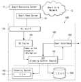
도 1은 스마트 그리드의 개략도이다.
도 2는 스마트 그리드의 주요 수요처인 가정에서의 전력관리네트워크(10)를 도시한 것이다.
도 3은 전력관리네트워크(10)의 블록 구성도 및 전력관리네트워크(10)에 연결가능한 로봇 청소기(100)의 블록 구성도를 도시한 것이다.
도 4는 외부의 전원 공급 장치(60)와 상기 로봇 청소기(100)의 충전 시스템을 도시한 블록 구성도이다.
도 5는, 스마트 그리드 정보 및 방송 콘텐츠와 관련하여 상기 로봇 청소기(100)의 블록 구성도를 도시한 도면이다.
도 6은, 본 발명의 제1 실시예에 따른 로봇 청소기의 배터리 충전 방법의 흐름도이다.
도 7 및 도 8은, 본 발명의 제1 실시예에 따른 로봇 청소기의 배터리 충전 방법을 설명하기 위한 도면들이다.
도 9는, 본 발명의 제2 실시예에 따른 로봇 청소기의 배터리 충전 방법의 흐름도이다.
도 10 내지 도 12는, 본 발명의 제2 실시예에 따른 로봇 청소기의 배터리 충전 방법을 설명하기 위한 도면들이다.Figure 1 is a schematic diagram of a smart grid.
FIG. 2 shows a
3 is a block diagram of the
4 is a block diagram showing a charging system of the external
5 is a block diagram of the
6 is a flowchart of a method of charging a battery of a robot cleaner according to the first embodiment of the present invention.
7 and 8 are views for explaining a battery charging method of the robot cleaner according to the first embodiment of the present invention.
9 is a flowchart of a method for charging a battery of a robot cleaner according to a second embodiment of the present invention.
10 to 12 are views for explaining a method of charging a battery of a robot cleaner according to a second embodiment of the present invention.
본 발명의 상술한 목적, 특징들 및 장점은 첨부된 도면과 관련된 다음의 상세한 설명을 통하여 보다 분명해질 것이다. 이하 첨부된 도면을 참조하여 본 발명에 따른 바람직한 실시예들을 상세히 설명한다. 명세서 전체에 걸쳐서 동일한 참조번호들은 동일한 구성요소들을 나타낸다. 또한, 본 발명과 관련된 공지 기능 혹은 구성에 대한 구체적인 설명이 본 발명의 요지를 불필요하게 흐릴 수 있다고 판단되는 경우, 그 상세한 설명을 생략한다.
The foregoing objects, features and advantages of the present invention will become more apparent from the following detailed description taken in conjunction with the accompanying drawings. DETAILED DESCRIPTION OF THE PREFERRED EMBODIMENTS Reference will now be made in detail to the preferred embodiments of the present invention, examples of which are illustrated in the accompanying drawings. Like reference numerals designate like elements throughout the specification. In the following description, well-known functions or constructions are not described in detail since they would obscure the invention in unnecessary detail.
도 1은 스마트 그리드의 개략도에 관한 것으로서, 스마트 그리드는 화력발전이나 원자력발전 또는 수력발전을 통하여 전력을 발생시키는 발전소와, 신재생에너지인 태양광 또는 풍력을 이용한 태양광 발전소와 풍력발전소를 포함한다.FIG. 1 is a schematic diagram of a smart grid. The smart grid includes a power plant generating electricity through thermal power generation, nuclear power generation, or hydroelectric power generation, and a photovoltaic power generation plant and a wind power generation plant using solar power or wind power .
그리고, 상기 화력발전 또는 원자력발전소 또는 수력발전소는 송전선을 통하여 전력소로 전력을 보내고, 전력소에서는 변전소로 전기를 보내어 전기가 가정이나 사무실 같은 수요처로 분배되도록 한다.The thermal power plant, nuclear power plant or hydroelectric power plant transmits electric power to the electric power plant through a transmission line, and electric power is sent to the substation in the electric power plant so that electric power is distributed to the consumer such as the home or the office.
그리고, 신재생 에너지에 의하여 생산된 전기도 변전소로 보내져 각 수요처로 분배되도록 한다. 그리고, 변전소에서 송전된 전기는 전력저장장치를 거쳐서 사무실이나 각 가정으로 분배된다.Electricity generated by renewable energy is also sent to the substation and distributed to each customer. Electricity transmitted from the substation is distributed to the office or each household through the electric power storage device.
가정용 전력관리네트워크(HAN, Home Area Network)를 사용하는 가정에서도 태양광이나 PHEV(하이브리드 전기자동차, Plug in Hybrid Electric Vehicle)에 장착된 연료전지를 통하여 전기를 자체적으로 생산하여 전기를 자체공급할 수 있고, 남는 전기는 스마트 미터를 통한 역전송에 의해 외부에 되팔수도 있다.Even at home using a home power network (HAN), it is possible to produce electricity by itself through the fuel cell installed in sunlight or PHEV (Hybrid Electric Vehicle, Plug in Hybrid Electric Vehicle) , And the remaining electricity may be returned to the outside by reverse transmission through the smart meter.
그리고, 사무실이나 가정에는 스마트 계측장치가 마련되어서 각 수요처에서 사용되는 전력 및 전력요금을 실시간을 파악할 수 있고, 이를 통하여 사용자는 현재 사용되는 전력량 및 전력요금을 인지하여 상황에 따라 전력소모량이나 전력요금을 줄이는 방안을 강구할 수 있다.In the office or the home, a smart measurement device is provided, so that the user can grasp the power and electric charge used in each customer in real time. Through this, the user can recognize the electric power and the electric charge currently used, Can be considered.
한편, 상기 발전소, 전력소, 저장장치 및 수요처는 양방향 통신이 되기 때문에 수요처에서 일방적으로 전기를 받도록 하는 것만을 떠나서, 수요처의 상황을 저장장치, 전력소, 발전소로 통지함으로써 수요처의 상황에 맞게 전기 생산 및 전기분배를 수행할 수 있게 된다.In addition, since the power plant, power station, storage device, and consumer are two-way communication, it is necessary to notify the storage device, the power station and the power station of the situation of the demanding place separately from the one- Electric distribution can be performed.
한편, 상기 스마트 그리드에서는 수요처의 실시간 전력관리 및 소요전력의 실시간 예측을 담당하는 에너지관리장치(EMS, Energy Management System) 및 전력의 소모량을 실시간으로 계측하는 계측장치(AMI,Advanced Metering infrastructure)가 중추적인 역할을 담당한다.Meanwhile, in the above-mentioned smart grid, an Energy Management System (EMS) and an Advanced Metering Infrastructure (AMI), which measure real-time power management of demanders and real-time power consumption, It is responsible for the role of
여기서 스마트 그리드 하에서의 계측장치는 오픈 아키텍쳐를 근거로 하여 소비자를 통합하려는 기반기술로서 소비자에게는 전기를 효율적으로 사용하도록 하고, 전력공급자에게는 시스템상의 문제를 탐지하여 시스템을 효율적으로 운영할 수 있는 능력을 제공한다.The measurement device under the Smart Grid is based on an open architecture and is an underlying technology to integrate consumers. It provides consumers with the ability to use electricity efficiently, and power suppliers to detect system problems and efficiently operate the system do.
여기서, 오픈 아키텍쳐란 일반적인 통신망과는 달리 스마트 그리드 시스템에서 전기기구가 어느 제조업체에서 제조되었는지 상관없이 모든 전기기구가 서로 연결될 수 있도록 하는 기준을 의미한다.Here, open architecture is a standard that allows all electric devices to be connected to each other regardless of which manufacturer manufactures the electric devices in a smart grid system, unlike a general communication network.
따라서, 상기 스마트 그리드에서 사용되는 계측장치는 "가격 대 장치(Prices to Devices)"와 같은 소비자 친화적인 효율성 개념을 가능케 한다. 즉, 전력시장의 실시간 가격신호가 각 가정에 설치된 에너지관리장치(EMS)를 통하여 중계되며, 에너지관리장치(EMS)는 각 전기장치와 통신을 하며 이를 제어하므로 사용자는 에너지관리장치(EMS)를 보고 각 전기장치의 전력정보를 인식하고 이를 기초로 소모전력량이나 전력요금 한계설정 등과 같은 전력정보처리를 수행함으로써 에너지 및 비용을 절약할 수 있다.Thus, the metering devices used in the Smart Grid enable consumer-friendly efficiency concepts such as "Prices to Devices ". That is, the real-time price signal of the electric power market is relayed through the energy management device (EMS) installed in each home. The energy management device (EMS) communicates with each electric device and controls it. It is possible to save the energy and cost by recognizing the power information of each electric device and performing the power information processing such as setting the consumed electric power or the electric power charge limit based on the information.
여기서 에너지관리장치(EMS)는, 사무실이나 가정에서 사용되는 로컬에너지관리장치(EMS)와, 상기 로컬에너지관리장치(EMS)와 양방향 통신을 하여 로컬에너지관리장치(EMS)에서 취합된 정보를 처리하는 중앙에너지관리장치(EMS)로 구성될 수 있다.Wherein the energy management device (EMS) communicates with a local energy management device (EMS) used in an office or a home and bi-directional communication with the local energy management device (EMS) to process information collected in a local energy management device And a central energy management device (EMS).
스마트 그리드에서 공급자와 수요자간의 전력정보에 관한 실시간 통신이 가능하게 되기 때문에, "실시간 전력망 반응"을 현실화시킬 수 있고, 이에 따라서, 피크 수요(peak demand)를 맞추는데 소요되는 높은 비용을 줄일 수 있다.
Since the smart grid enables real-time communication of power information between the supplier and the consumer, it is possible to realize a "real-time power grid reaction ", thereby reducing the high cost required to meet the peak demand.
도 2는 스마트 그리드의 주요 수요처인 가정에서의 전력관리네트워크(10)를 도시한 것이다.FIG. 2 shows a
상기 전력관리네트워크(10)는 각 가정에 공급되는 전력 및 전력요금을 실시간으로 측정할 수 있는 계측장치(스마트미터)(20) 또는 에너지관리장치(EMS)(30)를 포함한다.The
여기서 전력요금은 시간당 요금제를 기준으로 하여 과금될 수 있으며, 전력소모량이 급격하게 증대되는 시간구간에서는 시간당 전력요금이 비싸지게 되거나, 전력소모량이 상대적으로 적은 심야 시간구간과 같은 때에는 시간당 전력요금이 저렴해질 수 있다.Here, the electricity rate can be charged based on the hourly rate plan. In the time zone in which the electric power consumption is rapidly increased, the electricity rate per hour becomes high, or the electricity rate per hour is low when the electric power consumption is relatively low .
또한 전력요금은 전력수요가 적은 시간구간이나 전력수요가 많은 시간구간이나 동일하게 과금될 수 있다. 이때 전력수요가 증가되는 구간에서는 사용자가 절전을 할 경우 절전한 금액만큼 전력 소비자에게 리베이트로 되돌려 주도록 할 수도 있다.In addition, electric power charges can be charged at the same time at a time interval in which electric power demand is low or at a time interval in which electric power demand is high. At this time, in a period in which power demand is increased, the user may be allowed to return the rebate to the electric power consumer as much as the amount saved when the user performs the power saving.
여기서, 상기 에너지관리장치(EMS)(30)는 사용자의 조작이 가능한 입력버튼(32) 등을 구비한 단말기 형태로 마련될 수 있다.Here, the energy management device (EMS) 30 may be provided in the form of a terminal having an
상기 에너지관리장치(EMS)(30) 또는 상기 계측장치(스마트 미터)(20)는 다시 가정 내부의 네트워크망을 통하여 DTV(Digital Television), 냉장고, 세탁기, 건조기, 에어컨, 청소기, 로봇 청소기(100) 또는 조리기기, 조명장치 또는 차광장치와 같은 전자기기와 연결되어, 이들과 양방향 통신을 할 수 있다. 즉, 상기 에너지관리장치(30)는 상기 전력관리네트워크(10)에 포함된 전자기기들에서 소모되고 있는 전력을 관리, 전자기기들에 전력을 공급을 할 수 있으며, 경우에 따라서는 상기 전자기기들의 동작을 제어할 수도 있다. 또한 상기 에너지관리장치(30)는, DTV 또는 컴퓨터 등에 내장될 수도 있다.The energy management device (EMS) 30 or the measuring device (smart meter) 20 can be connected to a DTV (Digital Television), a refrigerator, a washing machine, a dryer, an air conditioner, a cleaner, ) Or an electronic device such as a cooking device, a lighting device, or a light shielding device so as to perform bi-directional communication with them. That is, the
집안 내부에서의 통신은 무선 또는 PLC(Power Line Communication; 전력선 통신)와 같은 유선을 통하여 이루어질 수 있다. 그리고, 각 전자기기는 다른 전자기기들과 연결되어 통신이 가능해지도록 배치될 수 있다.Communication inside the house can be done via wired lines such as wireless or PLC (Power Line Communication). Each of the electronic devices can be arranged to be connected to other electronic devices to enable communication.
한편, 상기 전력관리네트워크(10)에는 가정에 마련되는 보조전원(50), 즉, 태양광 발전장치 등과 같은 자가발전시설(51)과, 이러한 자가발전시설에서 발생하는 전력을 축전할 수 있는 축전지(52)를 포함한다.The
그리고, 상기 축전지(52) 이외에 연료전지(53)도 상기 전력관리네트워크(10)에 연결되어 보조전원으로서의 역할을 할 수 있다.In addition to the
여기서 상기 보조전원(50)은 전력회사와 같은 외부전원에서 전력을 공급받지 않는 상태에서 가정에 전력을 공급하는 역할을 한다.Here, the
이와 같은 보조전원에서 공급받을 수 있는 전력량 또는 보조전원(50)에 충전되어 있는 전력량은 상기 에너지관리장치(EMS)(30) 또는 상기 계측장치(스마트미터)(20)에 표시될 수 있다.The amount of power that can be supplied from the auxiliary power source or the amount of power that is charged to the
도 3은 전력관리네트워크(10)의 블록 구성도 및 전력관리네트워크(10)에 연결가능한 로봇 청소기(100)의 블록 구성도를 도시한 것이다.3 is a block diagram of the
여기서, 전력관리프로그램 운영주체(40)는 일반적인 발전장비(화력, 원자력, 수력)를 구비하거나 신재생에너지(태양광, 풍력, 지열) 등을 이용한 발전장비 등을 구비한 전력회사가 될 수 있으나 이에만 한정되는 것은 아니다.Here, the power management
상기 전력관리프로그램 운영주체(40)는 전력을 공급할 뿐만 아니라, 변동요금제와 관련한 정보를 각 가정에 제공하여 가정에서 이를 근거로 전력요금변동에 따른 전력요금 절약 전략을 세울 수 있도록 돕는 역할을 한다.The power
또한, 사용자가 전력요금을 절약할 수 있도록 가이드를 권장하고, 고액과금 시간구간에 대한 기준을 세워주거나 권장함으로써 사용자의 합리적인 전력소비를 돕는다. 이하에서는 이러한 전력관리프로그램 운영주체(40)가 갖는 전력공급원을 외부전원이라고 하겠다.It also encourages users to save on electricity bills and helps rational power consumption by establishing or recommending criteria for high-cost time intervals. Hereinafter, the power supply source of the power management program
상기 고액과금 시간구간이라 함은 전력수요의 폭증으로 인하여 시간당 전력요금이 소정기준요금 이상이 되어 전력요금이 다른 때보다 현저하게 높아지는 시간구간대를 말한다.The high-charge time zone refers to a time zone in which the electric power charge is higher than a predetermined standard charge due to the explosion of electric power demand, and the electric charge is significantly higher than the other electric power charges.
상기 전력관리네트워크(10)는 상술한 바와 같이 각 가정에 구비될 수 있는 보조전원 즉, 태양열 발전시설과 같은 자가발전시설(51), 축전지(52) 및 연료전지(52)를 포함하고 있다.The
여기서 상기 보조전원(50)은 상기 외부전원과 구별되고, 상기 외부전원과 별도로 전력을 가정에 공급할 수 있는 역할을 한다. 이러한 보조전원(50)과 상기 외부전원은 상기 계측장치(스마트미터)(20) 및 상기 에너지관리장치(EMS)(30)와 통신가능하게 연결된다. 그리고, 상기 계측장치(스마트미터)(20) 및 상기 에너지관리장치(EMS)(30)는 상기 전자기기들과 통신가능하게 마련된다. 따라서, 상기 각 전자기기는 상기 외부전원 및/또는 상기 보조전원을 모두 공급받을 수 있는 전원부를 구비하도록 설계될 수 있다.Here, the
여기서, 상기 에너지관리장치(EMS)(30)의 구성을 보면, 제어부(35), 입력부(38), 통신부(34) 및 표시부(39)를 포함하고 있으며, 상기 계측장치(스마트미터)(20)도, 제어부(25), 입력부(28), 통신부(24) 및 표시부(29)를 포함하고 있다.The
여기서, 상기 에너지관리장치(EMS)(30)나 계측장치(스마트미터)(20)는 로봇 청소기(100)와 통신가능하게 연결되며, 이를 위하여 상기 로봇 청소기(100)에는 상기 에너지관리장치(EMS)(30)의 통신부(34) 또는 상기 계측장치(스마트미터)(20)의 통신부(24)와 통신할 수 있는 제1 통신부(131)를 포함하는 통신부(130)가 구비된다.Here, the energy management device (EMS) 30 and the measurement device (smart meter) 20 are communicably connected to the
그리하여, 상기 로봇 청소기(100)에 구비되는 상기 제1 통신부(131)는 상기 에너지관리장치(EMS) 또는 상기 계측장치(20)로부터 실시간으로 변동되는 전력요금 정보 등과 같은 전력정보를 받을 수 있다.The
또한 도 3을 참조하면, 상기 로봇 청소기(100)는, 상기 통신부(130) 이외에도, 전원부(110), 입력부(120), 출력부(150), 메모리(160) 및 제어부(180)를 포함하여 구성될 수 있다.3, the
상기 전원부(110)는, 상기 외부전원 및/또는 상기 보조전원을 공급받아, 상기 로봇 청소기(100)를 구성하는 각 구성요소들의 동작에 필요한 전원을 공급한다.The
한편 상기 전원부(110)는, 외부의 전원 공급 장치로부터 유선 또는 무선으로 전원을 공급받을 수 있다.Meanwhile, the
도 4는 외부의 전원 공급 장치(60)와 상기 로봇 청소기(100)의 충전 시스템을 도시한 블록 구성도이다.4 is a block diagram showing a charging system of the external
예를 들어, 무선으로 상기 로봇 청소기(100)로 전원을 공급하기 위한 전원 공급 장치(60)는, 댁내에 설치될 수 있는데, 전원 공급부(61)와, 상기 전원 공급부(61)로부터 공급된 교류 전원을 직류 전원으로 변환시키는 AC/DC 변환부(62)와, 상기 AD/DC 변환부(62)에 의해서 변환된 직류 전원을 전파(Radio Frequency; RF)로 변환시키는 DC/RF 변환부(63)와, 상기 DC/RF 변환부(63)에서 변환된 전파를 상기 전원부(110)로 송신하는 송신부(64)를 포함할 수 있다.For example, a
외부전원으로부터 무선으로 전원을 공급받기 위해, 상기 전원부(110)는, 제2 통신부(132)와 RF/DC 변환부(170)를 포함할 수 있다.The
상기 제2 통신부(132)는 상기 송신부(64)로부터 송신된 전파를 수신하고, 상기 RF/DC 변환부(170)는 상기 제2 통신부(132)에서 수신된 전파를 직류 전원으로 변환시킨다.The
상기 제어부(180)는, 상기 직류 전원으로 상기 전원부(110)에 포함된 배터리(112)를 충전시킬 수 있다.The
한편, 상기 전원 공급 장치(60)는, 상기 로봇 청소기(100)의 상기 배터리(112)가 충전이 필요한 경우를 자동으로 감지하고, 상기 배터리(112)의 충전을 위해 전파를 상기 로봇 청소기(100)로 송신할 수도 있다.The
또한 상기 전원 공급 장치(60)는, 시간대별 전력요금 정보 및 전력수요 정보 중 적어도 하나를 포함하는 전력 정보를 수신할 수 있다. 그리고 상기 전원 공급 장치(60)는, 상기 수신된 전력 정보에 기초하여 상기 로봇 청소기(100)의 상기 배터리(112)를 충전을 수행할지 여부를 결정할 수 있다. 이에 관한 상세한 설명은 후술하기로 한다.Also, the
상기 입력부(120)는, 사용자가 상기 로봇 청소기(100)의 동작 제어를 위한 입력 데이터를 발생시킨다.The
상기 통신부(130)는, 전술한 바와 같이 상기 전력요금 정보 등과 같은 스마트 그리드와 관련된 전력 정보(이하에서, 스마트 그리드 정보라 함)를 수신하는 기능을 수행하는 제1 통신부(131)와, 상기 전원 공급 장치(60)로부터 전원을 공급받기 위한 제2 통신부(132) 이외에도, 상기 로봇 청소기(100)와 네트워크(예를 들어, 인터넷) 간의 통신을 가능하게 하는 하나 이상의 모듈을 포함할 수 있다.The
또한 상기 제1 통신부(131)는, 유선(예를 들어, 이더넷(ethernet), PLC 등) 또는 무선(예를 들어, 지그비(Zigbee) 등)으로 스마트 그리드 정보를 수신할 수 있다.Also, the
본 문서에서 언급되는 스마트 그리드 정보는, 전력 요금 정보를 포함한다. 상기 전력 요금 정보를 포함하는 상기 스마트 그리드 정보의 소스(source) 및 상기 스마트 그리드 정보의 송수신 방식은 매우 다양할 수 있다.The Smart Grid information referred to in this document includes power charge information. The source of the Smart Grid information including the power charge information and the transmission / reception method of the Smart Grid information can be very diverse.
예를 들어, 상기 전력 요금 정보는, 시간대별 전력요금 정보와 전력수요 정보 중 적어도 하나를 포함할 수 있다.For example, the power bill information may include at least one of power bill information by time zone and power demand information.
예를 들어, 상기 제1 통신부(131)는, 도 5를 참조하여 후술하는 스마트 운영 센터(11) 또는 스마트 그리드 네트워크(12) 또는 외부 네트워크 상에 존재하는 특정 서버로부터 상기 스마트 그리드 정보를 수신할 수 있다.For example, the
또한 예를 들어, 상기 제1 통신부(131)는, 유선 인터넷, 무선 인터넷, 휴대 인터넷, 이동통신망 등 다양한 통신 프로토콜을 통해 상기 스마트 그리드 정보를 수신할 수 있다.For example, the
한편 상기 로봇 청소기(100)는, 상기 제1 통신부(131)를 포함하지 않을 수 있다. 이때 상기 제1 통신부(131)는 상기 로봇 청소기(100) 외부에 독립된 형태로 존재할 수 있으며, 상기 제1 통신부(131)는 상기 로봇 청소기(100)와 유/무선으로 통신할 수 있다. 그리고 상기 제어부(180)는 상기 제1 통신부(131)를 통해 수신된 데이터를 처리할 수 있다. 예를 들어, 상기 제1 통신부(130)는 상기 로봇 청소기(100)와 통신 가능한 다른 전자 기기에 구비될 수 있다.Meanwhile, the
상기 출력부(150)는, 시각, 청각 또는 촉각 등과 관련된 출력을 발생시키기 위한 것으로서, 디스플레이부(151) 및 음향 출력부(152) 등을 포함할 수 있다. 상기 출력부(150)는 이외에도 촉각과 관련된 출력(예를 들어, 진동)을 발생시키기 위한 햅틱 모듈(154)을 더 포함할 수도 있다.The
상기 디스플레이부(151)는, 상기 로봇 청소기(100)에서 처리되는 정보를 표시 출력한다.The
상기 디스플레이부(151)는 액정 디스플레이(liquid crystal display), 박막 트랜지스터 액정 디스플레이(thin film transistor-liquid crystal display), 유기 발광 다이오드(organic light-emitting diode), 플렉시블 디스플레이(flexible display), 3차원 디스플레이(3D display) 중에서 적어도 하나를 포함할 수 있다. 상기 디스플레이부(151)는, 상기 로봇 청소기(100)의 구현 형태에 따라 2개 이상 존재할 수도 있다.The
한편 상기 로봇 청소기(100)는, 상기 디스플레이부(151)를 포함하지 않을 수 있다. 이때 상기 디스플레이부(151)의 상기 로봇 청소기(100) 외부에 독립된 형태로 존재하거나 다른 전자 기기에 구비될 수 있다. 그리고 상기 제어부(180)는 유선 및/또는 무선으로 상기 디스플레이부(151)를 제어할 수 있다.Meanwhile, the
상기 로봇 청소기(100)과 상기 디스플레이부(151)가 서로 별개의 독립된 형태로 존재하는 경우, 상기 로봇 청소기(100)와 상기 디스플레이부(151)는, 전원 공급 소스(source)를 공유할 수도 있고 공유하지 않을 수도 있다.The
상기 음향 출력부(152)는, 외부에서 수신되거나 상기 로봇 청소기(100)에서 생성되는 오디오 데이터를 출력한다. 즉 상기 음향 출력부(152)는, 상기 로봇 청소기(100)에서 수행되는 기능과 관련된 음향 신호를 출력할 수 있다.The
상기 음향 출력부(152)는, 스피커(speaker), 버저(Buzzer) 등이 포함될 수 있다. 또한 상기 음향 출력부(152)는, 이어폰잭을 통해 음향을 출력할 수 있다. 사용자는 상기 이어폰잭에 이어폰을 연결하여 출력되는 음향을 들을 수 있다.The
상기 메모리(160)는, 상기 제어부(180)의 동작을 위한 프로그램을 저장할 수 있고, 입/출력되는 데이터들(예를 들어, 오디오, 정지영상, 동영상 등)을 임시 또는 영구적으로 저장할 수도 있다.The
상기 메모리(160)는 플래시 메모리 타입(flash memory type), 하드디스크 타입(hard disk type), 멀티미디어 카드 마이크로 타입(multimedia card micro type), 카드 타입의 메모리(예를 들어 SD 또는 XD 메모리 등), 램(Random Access Memory, RAM), SRAM(Static Random Access Memory), 롬(Read-Only Memory, ROM), EEPROM(Electrically Erasable Programmable Read-Only Memory), PROM(Programmable Read-Only Memory) 자기 메모리, 자기 디스크, 광디스크 중 적어도 하나의 타입의 저장매체를 포함할 수 있다.The
상기 메모리(160)는, 도 5를 참조하여 후술하는 바와 같이, 상기 로봇 청소기(100)의 외부에 별도로 존재할 수도 있다. 상기 메모리(160)는, 스토리지(storage)로 호칭될 수도 있다.The
상기 로봇 청소기(100)는 인터넷(internet)상에서 상기 메모리(160)의 저장 기능을 수행하는 웹 스토리지(web storage)와 관련되어 동작할 수도 있다.The
상기 제어부(180)는, 통상적으로 상기 로봇 청소기(100)의 전반적인 동작을 제어한다.The
본 문서에서 설명되는 다양한 실시예는 예를 들어, 소프트웨어, 하드웨어 또는 이들의 조합된 것을 이용하여 컴퓨터 또는 이와 유사한 장치로 읽을 수 있는 기록매체 내에서 구현될 수 있다.The various embodiments described herein may be implemented in a recording medium readable by a computer or similar device using, for example, software, hardware, or a combination thereof.
하드웨어적인 구현에 의하면, 본 문서에서 설명되는 실시예는 ASICs (application specific integrated circuits), DSPs (digital signal processors), DSPDs (digital signal processing devices), PLDs (programmable logic devices), FPGAs (field programmable gate arrays, 프로세서(processors), 제어기(controllers), 마이크로 컨트롤러(micro-controllers), 마이크로 프로세서(microprocessors), 기능 수행을 위한 전기적인 유닛 중 적어도 하나를 이용하여 구현될 수 있다. 일부의 경우에 그러한 실시예들이 상기 제어부(180)에 의해 구현될 수 있다.According to a hardware implementation, the embodiments described in this document may be implemented as application specific integrated circuits (ASICs), digital signal processors (DSPs), digital signal processing devices (DSPDs), programmable logic devices (PLDs), field programmable gate arrays Microprocessors, microprocessors, electrical units for performing functions, etc. In some cases, such an embodiment may be implemented using any of a variety of hardware, May be implemented by the
소프트웨어적인 구현에 의하면, 절차나 기능과 같은 실시예들은 적어도 하나의 기능 또는 작동을 수행하게 하는 별개의 소프트웨어 모듈과 함께 구현될 수 있다. 소프트웨어 코드는 적절한 프로그램 언어로 쓰여진 소프트웨어 어플리케이션에 의해 구현될 수 있다. 또한, 소프트웨어 코드는 상기 메모리(160)에 저장되고, 상기 제어부(180)에 의해 실행될 수 있다.
In accordance with a software implementation, embodiments such as procedures or functions may be implemented with separate software modules that perform at least one function or operation. The software code may be implemented by a software application written in a suitable programming language. The software code may also be stored in the
도 5는, 스마트 그리드 정보 및 방송 콘텐츠와 관련하여 상기 로봇 청소기(100)의 블록 구성도를 도시한 도면이다.5 is a block diagram of the
도 5를 참조하면, 상기 로봇 청소기(100)의 상기 제어부(180)는, 스마트 그리드 엔진(181), 클리닝 제어 엔진(Cleaning Control Engine; CCE, 182) 및 UI 처리부(183)를 포함할 수 있다.5, the
상기 스마트 그리드 엔진(181)은, 상기 통신부(130)를 통해 수신된 스마트 그리드 정보를 상기 로봇 청소기(100)에서 사용할 수 있는 형태로 가공하여 상기 로봇 청소기(100)의 내부 또는 외부에 존재하는 상기 스토리지(160)에 저장하는 역할을 수행할 수 있다.The
여기서 상기 제1 통신부(130)는, 도 5에 도시된 바와 같이, 스마트 그리드 네트워크(12)로부터 가정 외부에 존재하는 스마트 운영 센터(11)를 통해 상기 스마트 그리드 정보를 직접 수신하거나, 상기 스마트 그리드 네트워크(12)로부터 가정 내부에 존재하는 스마트 홈 서버(10)를 통해 상기 스마트 그리드 정보를 수신할 수 있다.5, the
상기 스마트 운영 센터(11)는 전술한 가정 외부의 상기 에너지관리장치(EMS)의 다른 표현이고, 상기 스마트 홈 서버(10)는 전술한 상기 전력관리네트워크(10)의 다른 표현이다.The
상기 클리닝 제어 엔진(182)는, 청소 작업을 수행하는 클리닝 시스템(Cleaning System, 140)을 제어하여 청소 작업과 관련된 전반적인 동작을 제어하는 기능을 수행할 수 있다.The cleaning
상기 클리닝 시스템(140)은, 상기 로봇 청소기(100)에 구비되고, 상기 로봇 청소기(100)를 구동하는 구동부(141)를 포함할 수 있다.The
상기 UI 처리부(183)는, 후술하는 다양한 실시예들에서 언급되는 각종 사용자 인터페이스(user interface; UI)를 생성, 저장 및 출력에 관계되는 기능과, 상기 사용자 인터페이스를 통해 수신된 사용자 입력을 처리하는 기능을 수행할 수 있다.
The
이하 본 발명의 실시예들을 설명하기로 한다.Hereinafter, embodiments of the present invention will be described.
도 6은, 본 발명의 제1 실시예에 따른 로봇 청소기의 배터리 충전 방법의 흐름도이다. 도 7 및 도 8은, 본 발명의 제1 실시예에 따른 로봇 청소기의 배터리 충전 방법을 설명하기 위한 도면들이다.6 is a flowchart of a method of charging a battery of a robot cleaner according to the first embodiment of the present invention. 7 and 8 are views for explaining a battery charging method of the robot cleaner according to the first embodiment of the present invention.
본 발명의 제1 실시예에 따른 로봇 청소기의 배터리 충전 방법은, 도 1 내지 도 5를 참조하여 설명한 상기 환경 및 상기 로봇 청소기(100)에서 구현될 수 있다.The method for charging the battery of the robot cleaner according to the first embodiment of the present invention can be implemented in the environment and the
이하 필요한 도면들을 참조하여, 본 발명의 제1 실시예에 따른 로봇 청소기의 배터리 충전 방법과, 이를 구현하기 위한 상기 로봇 청소기(100)의 동작을 상기 제어부(180)를 중심으로 상세히 설명하기로 한다.Hereinafter, the method for charging the battery of the robot cleaner according to the first embodiment of the present invention and the operation of the
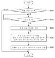
도 6을 참조하면, 상기 제어부(180)는, 전술한 바와 같이, 상기 제1 통신부(131)를 통하여 시간대별 전력요금 정보를 포함하는 스마트그리드 정보를 수신할 수 있다[S100].Referring to FIG. 6, the
상기 제어부(180)는, 상기 배터리(112)의 충전이 필요한지 여부를 판단할 수 있다[S110].The
상기 배터리(112)의 충전 필요 여부는, 다양한 기준에 의해 판단될 수 있다.The necessity of charging the
예를 들어, 상기 제어부(180)는, 사용자로부터 상기 입력부(12)를 통해 상기 배러티(122)를 충전하라는 명령을 수신할 수 있다.For example, the
또한 예를 들어, 상기 제어부(180)는, 미리 설정된 기준에 따라 상기 배터리(112)의 충전 잔량이 기준치 이하가 되면, 자동으로 상기 배터리(112)를 충전할 필요가 있는 경우로 판단할 수 있다.Also, for example, the
상기 제어부(180)는, 상기 S110 단계의 판단 결과, 상기 배터리(112)의 충전이 필요한 상황이라고 판단하는 경우, 상기 수신된 시간대별 전력요금 정보를 참조하여 현재 시각의 전력 요금이 제1 기준치 이상인지를 판단할 수 있다[S120].If it is determined that the
상기 제어부(180)는, 상기 S120 단계의 판단 결과, 현재 시각의 전력 요금이 상기 제1 기준치 이상이 아닌 경우, 상기 배터리(112)의 충전을 수행할 수 있다[S160].As a result of the determination in step S120, the
이때 상기 배터리(112)의 충전은, 유선 방식 또는 무선 방식으로 이루어질 수 있다.At this time, the
상기 제어부(180)는, 상기 S120 단계의 판단 결과, 현재 시각의 전력 요금이 상기 제1 기준치 이상인 경우, 상기 배터리(112)의 충전을 위한 추천 시각을 포함하는 충전 추천 정보를 제공할 수 있다[S130].As a result of the determination in step S120, the
예를 들어 도 7을 참조하면, 상기 제어부(180)는 상기 충전 추천 정보를 포함하는 제1 사용자 인터페이스(User Interface; UI, 70)를 상기 디스플레이부(151)에 제공할 수 있다.For example, referring to FIG. 7, the
도 7에 도시된 바와 같이, 상기 제1 사용자 인터페이스(70)는, 상기 배터리(112)의 충전을 위한 추천 시각에 관한 정보(71)를 포함할 수 있다.As shown in FIG. 7, the
도 8은, 도 7에 도시된 사용자 인터페이스의 다른 예를 도시하고 있다. 도 8을 참조하면, 상기 제어부(180)는, 도 7에 도시된 제1 사용자 인터페이스(70)와 마찬가지로, 상기 배터리(112)의 충전을 위한 추천 시각에 관한 정보(75)를 포함하는 충전 추천 정보를 제공하기 위한 제2 사용자 인터페이스(74)를 상기 디스플레이부(151)에 표시할 수 있다.Fig. 8 shows another example of the user interface shown in Fig. Referring to FIG. 8, the
도 8에 도시된 상기 제2 사용자 인터페이스(74)는, 상기 배터리(112)를 즉시 충전할 경우에 소요되는 비용에 관한 정보와, 충전 추천 시각(4시간 후)에 충전할 경우에 소요되는 비용에 관한 정보를 제공하고 있다.The
한편, 상기 제1 사용자 인터페이스(70)와 상기 제2 사용자 인터페이스(74)에 포함되는 상기 충전 추천 정보는, 상기 디스플레이부(151)를 통해서 뿐만이 아니라, 상기 음향 출력부(152)를 통해 음성으로 출력될 수 있다.The charging recommendation information included in the
상기 제어부(180)는, 상기 수신된 시간대별 전력요금 정보에 따라, 상기 충전 추천 시각을 결정할 수 있다.The
예를 들어, 상기 제어부(180)는, 예측할 수 있는 범위 내에서 전력요금이 가장 저렴한 시간 구간을 고려하여 상기 충전 추천 시각을 결정할 수 있다.For example, the
여기서 상기 제어부(180)는, 상기 배터리(112)를 완충하는데 걸리는 소요 시간을 고려하여 상기 배터리(112)를 완충하는데 소요되는 비용을 산출하고, 상기 소요 비용에 따라 상기 충전 추천 시각을 결정할 수 있다.Here, the
한편, 상기 충전 추천 정보는, 외부의 전자 기기를 통해 출력될 수 있다. 여기서 상기 제어부(180)는, 상기 충전 추천 정보를 상기 외부의 전자 기기로 전송하여 상기 외부 전자 기기에서 출력되도록 제어할 수 있다.Meanwhile, the charging recommendation information may be output through an external electronic device. Here, the
예를 들어, 상기 제어부(180)는, 사용자의 핸드폰과 같은 이동 단말기로 상기 충전 추천 정보를 전송할 수 있다. 또한 예를 들어, 상기 제어부(180)는, 댁내에 존재하는 DTV로 상기 충전 추천 정보를 전송할 수 있다.For example, the
또한 상기 제어부(180)는, 상기 클리닝 시스템(140)을 제어하여 청소 작업을 수행하는 중, 상기 충전 추천 정보를 출력할 수도 있다.Also, the
예를 들어, 상기 제어부(180)는, 청소 작업을 수행하던 중, 상기 배터리(112)의 잔량이 기준치 이하가 됨에 따라 충전을 필요로 하는 경우, 상기 충전 추천 정보를 출력할 수 있다.For example, when performing the cleaning operation, the
상기 제어부(180)는, 상기 제1 사용자 인터페이스(70) 또는 상기 제2 사용자 인터페이스(74)를 통해 사용자의 확인을 수신하는지를 판단하여[S140], 사용자의 확인이 있으면 상기 S130 단계에서 제공된 추천 시각이 도래하는지를 판단하고[S150], 상기 추천 시각이 도래하는 경우 상기 배터리(112)의 충전을 수행할 수 있다.The
여기서 상기 사용자의 확인은, 상기 S130 단계에서 제공된 상기 충전 추천 시각에 충전을 수행할 것인지에 대한 사용자의 확인을 의미한다.Here, the confirmation of the user means that the user confirms whether or not to perform the charging at the charging recommendation time provided in step S130.
예를 들어, 도 7에 도시된 상기 제1 사용자 인터페이스(70)는, 상기 충전 추천 시각(71)에 상기 배터리(112)를 충전하는 것에 대한 사용자의 승낙을 수신하기 위한 승낙 버튼(72)과, 사용자의 거절을 수신하기 위한 거부 버튼(73)을 포함할 수 있다.For example, the
또한 예를 들어, 도 8에 도시된 상기 제2 사용자 인터페이스(74)는, 지금 충전을 수행하라는 명령을 수신하기 위한 버튼(76)과, 충전 추천 시각(4시간 후)에 충전을 수행하라는 명령을 수신하기 위한 버튼(77)과, 충전을 수행하지 말라는 명령을 수신하기 위한 버튼(78)을 포함할 수 있다.8 also includes a
사용자는 상기 제1 사용자 인터페이스(70) 및 상기 제2 사용자 인터페이스(74)에 포함된 각종 버튼을 선택함으로써, 자신이 원하는 명령을 상기 로봇 청소기(100)로 전달할 수 있다.The user can select the various buttons included in the
상기 디스플레이부(151)가 터치스크린으로 구현되는 경우, 사용자는 상기 각종 버튼을 손가락으로 터치하여 선택할 수 있다. 또는 사용자는 상기 입력부(120)를 조작하여 상기 각종 버튼을 선택할 수도 있다.When the
상기 제어부(180)는, 상기 S140 단계의 판단 결과, 상기 제1 사용자 인터페이스(70) 또는 상기 제2 사용자 인터페이스(74)를 통해 상기 사용자의 확인을 수신하지 못한 경우, 상기 배터리(112)의 충전 모드가 자동 충전 모드로 설정되어 있는지를 판단하여[S170], 자동 충전 모드로 설정되어 있지 않으면 아무런 동작을 수행하지 않을 수 있다.If the
또한 상기 제어부(180)는, 상기 S170 단계의 판단 결과, 상기 배터리(112)의 충전 모드가 자동 충전 모드로 설정되어 있으면, 상기 제1 사용자 인터페이스(70) 또는 상기 제2 사용자 인터페이스(74)를 통해 상기 사용자의 확인을 받지 않았음에도 불구하고, 즉시 상기 배터리(112)의 충전을 수행할 수도 있다[S160].If the charging mode of the
한편, 전술한 바와 같이, 상기 로봇 청소기(100)가 수신하는 전력 정보는, 전력수요 정보를 포함할 수 있다.Meanwhile, as described above, the power information received by the
상기 로봇 청소기(100)는, 상기 전력수요 정보에 따라 상기 배터리(112)의 충전 여부를 결정하고, 상기 결정에 따라 상기 배터리(112)를 충전할 수도 있다.The
예를 들어, 상기 로봇 청소기(100)는, 상기 수신된 전력수요 정보에 따라 현재 시간구간이 전력수요가 높은 시간구간인 경우, 상기 배터리(112)를 충전하지 않고, 전력수요가 낮은 시간구간에 상기 배터리(112)를 충전하도록 유도할 수 있다.For example, when the current time interval is a time interval in which the demand for electric power is high according to the received electric power demand information, the
상기 로봇 청소기(100)가 상기 전력수요 정보에 따라 상기 배터리(112)의 충전을 제어하는 방식은, 상기 시간대별 전력요금 정보에 따라 상기 배터리(112)의 충전을 제어하는 방식과 동일하다.The manner in which the
한편, 상기 로봇 청소기(100)의 상기 제어부(180)는, 상기 시간대별 전력요금 정보 및 상기 전력수요 정보를 참조하여, 현재 시간구간이 전력요금 및 전력수요의 기준에 모두 부합하는 경우, 상기 배터리(112)의 충전을 수행할 수도 있다.The
또한, 상기 전원 공급 장치(60)가 상기 배터리(112)의 충전 여부를 결정할 수 있는 경우, 상기 전원 공급 장치(60)는, 상기 시간대별 전력요금 정보 및 상기 전력수요 정보 중 적어도 하나에 따라, 상기 배터리(112)의 충전 여부를 결정할 수 있다.When the
예를 들어, 상기 로봇 청소기(100)의 상기 제어부(180)가 상기 배터리(112)의 충전 여부를 결정하는, 전술한 방식과 동일하게, 상기 전원 공급 장치(60)는, 상기 시간대별 전력요금 정보 및 상기 전력수요 정보 중 적어도 하나에 따라, 현재 시간구간이 전력요금 기준 및 전력수요 기준 중 적어도 하나를 만족하는 경우, 상기 배터리(112)를 충전하도록 전파를 상기 로봇 청소기(100)로 송신할 수 있다.
For example, as in the above-described manner in which the
도 9는, 본 발명의 제2 실시예에 따른 로봇 청소기의 배터리 충전 방법의 흐름도이다. 도 10 내지 도 12는, 본 발명의 제2 실시예에 따른 로봇 청소기의 배터리 충전 방법을 설명하기 위한 도면들이다.9 is a flowchart of a method for charging a battery of a robot cleaner according to a second embodiment of the present invention. 10 to 12 are views for explaining a method of charging a battery of a robot cleaner according to a second embodiment of the present invention.
본 발명의 제2 실시예에 따른 로봇 청소기의 배터리 충전 방법은, 도 1 내지 도 5를 참조하여 설명한 상기 환경 및 상기 로봇 청소기(100)에서 구현될 수 있다.The method for charging the battery of the robot cleaner according to the second embodiment of the present invention can be implemented in the environment and the
이하 필요한 도면들을 참조하여, 본 발명의 제2 실시예에 따른 로봇 청소기의 배터리 충전 방법과, 이를 구현하기 위한 상기 로봇 청소기(100)의 동작을 상기 제어부(180)를 중심으로 상세히 설명하기로 한다.Hereinafter, the method for charging the battery of the robot cleaner according to the second embodiment of the present invention and the operation of the
여기서, 본 발명의 제1 실시예와 마찬가지로, 상기 로봇 청소기(100)는, 상기 시간대별 전력요금 정보를 수신할 수 있는 것을 전제로 한다.Here, as in the first embodiment of the present invention, the
도 9를 참조하면, 상기 제어부(180)는, 상기 배터리(112)의 충전 모드가 자동 충전 모드로 설정되어 있는지를 판단한다[S200].Referring to FIG. 9, the
상기 제어부(180)는, 상기 배터리(112)의 충전 모드가 자동 충전 모드로 설정되어 있는 경우, 상기 배터리(112)를 충전할 필요가 있는지를 판단하여[S210], 충전할 필요가 있으면, 상기 배터리(112)를 충전하는데 소요되는 시간을 산출할 수 있다[S220].If the charging mode of the
상기 S220 단계에서 산출되는 충전 소요 시간은, 일반 충전 모드로 충전하는데 걸리는 소요 시간과, 급속 충전 모드로 충전하는데 걸리는 소요 시간을 포함할 수 있다.The required charging time calculated in step S220 may include a time required for charging in the normal charging mode and a time required for charging in the rapid charging mode.
상기 제어부(180)는, 상기 충전 소요 시간과 시간대별 전력 요금을 고려하여 일반 충전 모드와 급속 충전 모드 중 어느 하나를 선택하고[S230], 상기 선택된 충전 모드로 상기 배터리(112)의 충전을 수행할 수 있다[S240].The
도 10 내지 도 12는, 충전 소요 시간과 시간대별 전력 요금을 고려한 충전 모드의 선택을 설명하기 위한 도면들이다.FIGS. 10 to 12 are diagrams for explaining the selection of the charging mode considering the charge time and the power charge by time.
도 10 내지 도 12에서, T1은 현재 시각을 나타낸다. 상기 현재 시각은 물리적으로 정확한 현재 시각 뿐만 아니라 상기 배터리(112)의 충전을 시작하고자 하는 시각을 포함할 수 있다.10 to 12, T1 represents the current time. The current time may include not only a physically correct current time but also a time to start charging of the
또한 T2는 일반 충전 모드로 상기 배터리(112)를 충전하는데 소요되는 시간을 나타내고, T5는 급속 충전 모드로 상기 배터리(112)를 충전하는데 소요되는 시간을 나타낸다.T2 represents the time required for charging the
그리고 T4는, 고액과금 시간구간으로 진입하는 시각을 나타낸다.And T4 represents the time at which the high billing time period is entered.
예를 들어, 도 10을 참조하면, 현재 시각(T1)으로부터 T4가 도래하기 이전에 상기 일반 충전 모드로 상기 배터리(112)를 완충할 수 있는 경우, 상기 제어부(180)는 상기 배터리(112)를 상기 일반 충전 모드로 충전할 수 있다.For example, referring to FIG. 10, when the
즉, 상기 제어부(180)는, 상기 일반 충전 모드로 상기 배터리(112)를 완충하는데 필요한 소요 시간(T2) 동안 전력요금이 기준치(B) 이하를 유지하는 경우, 상기 일반 충전 모드로 상기 배터리(112)를 충전할 수 있다.That is, when the power charge is maintained below the reference value B for the required time (T2) required for buffering the
또한 예를 들어, 도 11을 참조하면, 현재 시각(T1)으로부터 T4가 도래하기 이전에 상기 일반 충전 모드로 상기 배터리(112)를 완충할 수 없는 경우, 상기 제어부(180)는, T4가 도래하기 이전에 상기 급속 충전 모드로 상기 배터리(112)를 완충할 수 있는지를 판단한다.11, if the
여기서, 상기 제어부(180)는, T4가 도래하기 이전에 상기 급속 충전 모드로 상기 배터리(112)를 완충할 수 있으면, 상기 배터리(112)를 상기 급속 충전 모드로 충전할 수 있다.Here, the
즉, 상기 제어부(180)는, 상기 일반 충전 소요 시간(T2) 동안 전력요금이 상기 기준치(B) 이하를 유지하지 않고 상기 급속 충전 모드로 상기 배터리(112)를 완충하는데 필요한 소요 시간(T5) 동안 전력요금이 상기 기준치(B) 이하를 유지하는 경우, 상기 급속 충전 모드로 상기 배터리(112)를 충전할 수 있다.That is, the
또한 예를 들어, 도 12를 참조하면, 현재 시각(T1)으로부터 T4가 도래하기 이전에 상기 일반 충전 모드 및 상기 급속 충전 모드 중 어떠한 충전 모드로도 상기 배터리(112)를 완충할 수 없는 경우, 상기 제어부(180)는, 상기 배터리(112)의 충전을 수행하지 않을 수 있다.For example, referring to FIG. 12, if the
즉, 상기 제어부(180)는, 상기 급속 충전 소요 시간(T5) 동안에도 전력요금이 상기 기준치(B) 이하를 유지하지 않는 경우, 상기 배터리(112)의 충전을 수행하지 않을 수 있다.That is, the
한편, 도 12의 경우, 상기 제어부(180)는, 상기 일반 충전 모드 및 상기 급속 충전 모드 중 어느 하나의 모드로 상기 배터리(112)의 충전을 수행하되, 상기 T4가 도래하면 상기 충전을 중지할 수도 있다.12, the
전술한 바와 같이, 상기 제어부(180)는, 상기 일반 충전 모드 및 상기 급속 충전 모드 중 어느 하나의 모드를 자동으로 선택하고, 상기 자동 선택된 충전 모드로 상기 배터리(112)의 충전을 수행할 수 있다.As described above, the
또한, 상기 제어부(180)는, 상기 일반 충전 모드 및 상기 급속 충전 모드 중 어느 하나의 모드로 상기 배터리(112)의 충전을 수행하기 전, 사용자의 확인을 얻기 위한 사용자 인터페이스를 제공할 수 있다.Also, the
사용자는 상기 제공되는 사용자 인터페이스를 통해 상기 일반 충전 모드 및 상기 급속 충전 모드 중 어느 하나의 충전 모드를 선택할 수 있다. 상기 제어부(180)는, 상기 선택된 충전 모드로 상기 배터리(112)의 충전을 수행할 수 있다.The user can select any one of the normal charging mode and the quick charging mode through the provided user interface. The
특히, 상기 제어부(180)는, 전술한 실시예에 따라 상기 급속 충전 모드로 상기 배터리(112)의 충전을 수행하는 경우, 사용자의 확인을 얻기 위한 사용자 인터페이스를 제공한 후, 상기 사용자 인터페이스를 통해 사용자의 확인을 수신한 때에 상기 배터리(112)를 상기 급속 충전 모드로 충전할 수 있다.
Particularly, when the charging of the
상기에서는, 로봇 청소기(100)를 기준으로 상기 로봇 청소기(100)에 구비되는 배터리(112)의 충전과 관련된 실시예들을 설명하였다.Embodiments related to the charging of the
그러나, 본 문서에서 개시되는 기술적 사상이 상기 로봇 청소기(100)에만 적용될 수 있는 것은 아니다. 즉, 본 문서에서 개시되는 기술적 사상은, 상기 로봇 청소기(100) 뿐만 아니라, 유선 또는 무선으로 충전 가능한 배터리를 구비하는 모든 전자 기기에서 구현될 수 있다.
However, the technical idea disclosed in this document can not be applied to the
상기에서 설명한 본 발명에 의한 전자 기기의 배터리 충전 방법은, 컴퓨터에서 실행시키기 위한 프로그램으로 컴퓨터로 읽을 수 있는 기록매체에 기록하여 제공될 수 있다.The above-described battery charging method for an electronic apparatus according to the present invention can be provided by being recorded on a computer-readable recording medium as a program to be executed by a computer.
본 발명에 의한 전자 기기의 배터리 충전 방법은, 소프트웨어를 통해 실행될 수 있다. 소프트웨어로 실행될 때, 본 발명의 구성 수단들은 필요한 작업을 실행하는 코드 세그먼트들이다. 프로그램 또는 코드 세그먼트들은 프로세서 판독 가능 매체에 저장되거나 전송 매체 또는 통신망에서 반송파와 결합된 컴퓨터 데이터 신호에 의하여 전송될 수 있다.The battery charging method of the electronic device according to the present invention can be executed through software. When executed in software, the constituent means of the present invention are code segments that perform the necessary tasks. The program or code segments may be stored in a processor readable medium or transmitted by a computer data signal coupled with a carrier wave in a transmission medium or a communication network.
컴퓨터가 읽을 수 있는 기록매체는 컴퓨터 시스템에 의하여 읽혀질 수 있는 데이터가 저장되는 모든 종류의 기록 장치를 포함한다. 컴퓨터가 읽을 수 있는 기록 장치의 예로는, ROM, RAM, CD-ROM, DVD±ROM, DVD-RAM, 자기 테이프, 플로피 디스크, 하드 디스크(hard disk), 광데이터 저장장치 등이 있다. 또한 컴퓨터가 읽을 수 있는 기록매체는 네트워크로 연결된 컴퓨터 장치에 분산되어 분산방식으로 컴퓨터가 읽을 수 있는 코드가 저장되고 실행될 수 있다.
A computer-readable recording medium includes all kinds of recording apparatuses in which data that can be read by a computer system is stored. Examples of the computer-readable recording device include a ROM, a RAM, a CD-ROM, a DVD 占 ROM, a DVD-RAM, a magnetic tape, a floppy disk, a hard disk, The computer-readable recording medium may also be distributed to networked computer devices so that computer readable code can be stored and executed in a distributed manner.
이상에서 설명한 본 발명은, 본 발명이 속하는 기술분야에서 통상의 지식을 가진 자에 있어 본 발명의 기술적 사상을 벗어나지 않는 범위 내에서 여러 가지 치환, 변형 및 변경이 가능하므로 전술한 실시예 및 첨부된 도면에 의해 한정되는 것이 아니다. 또한 본 문서에서 설명된 실시예들은 한정되게 적용될 수 있는 것이 아니라, 다양한 변형이 이루어질 수 있도록 각 실시예들의 전부 또는 일부가 선택적으로 조합되어 구성될 수도 있다.It will be apparent to those skilled in the art that various modifications and variations can be made in the present invention without departing from the spirit or scope of the invention. The present invention is not limited to the drawings. In addition, the embodiments described in this document can be applied to not only the present invention, but also all or some of the embodiments may be selectively combined so that various modifications can be made.
60: 전원 공급 장치100: 로봇 청소기
110: 전원부130: 통신부
150: 출력부160: 메모리(스토리지)
180: 제어부60: power supply 100: robot cleaner
110: power supply unit 130:
150: output section 160: memory (storage)
180:
Claims (19)
Translated fromKorean스마트 그리드(Smart Grid)와 관련된 시간대별 전력요금 정보를 서버로부터 수신하는 제1 수신부를 포함하는 통신부; 및
상기 배터리를 충전하는 경우, 상기 수신된 전력요금 정보 및 상기 충전에 소요되는 시간을 고려하여, 급속 충전 모드 및 일반 충전 모드 중 어느 하나의 충전 모드를 선택하여 상기 충전을 수행하는 제어부를
포함하고,
상기 제어부는, 청소 작업을 수행하는 중, 상기 배터리의 잔량이 기준치 이하게 되면 상기 수신된 전력요금 정보를 이용하여 충전 추천 시간을 외부의 전자 기기로 출력하고, 상기 외부의 전자 기기를 통해 상기 출력된 충전 추천 시간에 상기 배터리를 충전하는 것에 대한 사용자 승낙 입력을 수신하는 경우, 상기 배터리를 급속 충전 모드로 충전하는데 소요되는 시간과 일반 충전 모드로 충전하는데 소요되는 시간을 산출하고,
상기 배터리의 충전 추천 시간부터 상기 전력요금 정보가 고액과금 시간 구간으로 진입하기 전에 상기 일반 충전 모드로 상기 배터리를 완충할 수 있는 경우, 상기 배터리를 일반 충전 모드로 충전하도록 제어하고,
상기 배터리의 충전 시작 시간부터 상기 전력요금 정보가 고액과금 시간 구간으로 진입하기 전에 상기 일반 충전 모드로 상기 배터리를 완충할 수 없고 상기 급속 충전 모드로 완충할 수 있는 경우, 상기 배터리를 급속 충전 모드로 충전하도록 제어하고,
상기 배터리의 충전 시작 시간부터 상기 전력요금 정보가 고액과금 시간 구간으로 진입하기 전에 상기 일반 충전 모드 및 상기 급속 충전 모드 중 어느 모드로도 상기 배터리를 완충할 수 없는 경우, 상기 고액과금 시간 구간에 진입하기 전까지 상기 일반 충전 모드 또는 상기 급속 충전 모드로 상기 배터리를 충전한 후, 상기 고액과금 시간 구간에 진입하는 경우, 상기 배터리 충전을 중지하는 것을 특징으로 하는 전자 기기.A power supply unit including a battery;
A communication unit including a first receiving unit for receiving time-based power charge information associated with a Smart Grid from a server; And
A controller for selecting one of the rapid charging mode and the normal charging mode to perform the charging in consideration of the received power charge information and the time required for charging the battery,
Including,
Wherein the control unit outputs a charging recommendation time to an external electronic device using the received electric power charge information when the remaining amount of the battery becomes less than a reference value during a cleaning operation, When the user acceptance input for charging the battery at the recommended charging time is received, the time required for charging the battery in the rapid charging mode and the time required for charging in the normal charging mode are calculated,
And controls the charging of the battery in the normal charging mode when the battery can be buffered in the normal charging mode before the electric power charge information enters the high charge charging time period from the recommended charging time of the battery,
If the battery can not be fully charged in the normal charge mode before the power charge information enters the high charge charging time period from the charge start time of the battery and the battery can be fully charged in the rapid charge mode, To be charged,
If the battery can not be buffered in either the normal charging mode or the rapid charging mode before the electric power charge information enters the high-charge charging time period from the charging start time of the battery, Wherein the charging of the battery is stopped when the battery is charged in the normal charging mode or the rapid charging mode before the high-charge charging time period.
상기 전자 기기는, 로봇 청소기이고,
상기 전원 공급부로부터 전원을 공급받아 상기 로봇 청소기를 구동하는 구동부를 더 포함하는 전자 기기.The method according to claim 6,
The electronic device is a robot cleaner,
And a driving unit for receiving the power from the power supply unit and driving the robot cleaner.
상기 통신부는, 전원이 변환된 전파를 수신하는 제2 수신부를 더 포함하고,
상기 제어부는, 상기 제2 수신부를 통해 수신된 상기 전파를 전원으로 변환시켜 상기 충전을 수행하는 것을 특징으로 하는 전자 기기.The method according to claim 6,
Wherein the communication unit further includes a second receiving unit for receiving radio waves whose power has been converted,
Wherein the control unit converts the radio wave received through the second receiving unit into a power source to perform the charging.
시간대별 전력요금 정보를 서버로부터 수신하는 단계;
청소 작업을 수행하는 중, 상기 배터리의 잔량이 기준치 이하게 되면 상기 수신된 전력요금 정보를 이용하여 충전 추천 시간을 외부의 전자 기기로 출력하는 단계;
상기 외부의 전자 기기를 통해 상기 출력된 충전 추천 시간에 상기 배터리를 충전하는 것에 대한 사용자 승낙 입력을 수신하는 경우, 상기 배터리를 급속 충전 모드로 충전하는데 소요되는 시간과 일반 충전 모드로 충전하는데 소요되는 시간을 산출하는 단계;
상기 산출된 시간을 고려하여, 급속 충전 모드와 일반 충전 모드 중 어느 하나의 충전 모드를 선택하는 단계; 및
상기 선택된 충전 모드로 상기 배터리를 충전하는 단계를
포함하고,
상기 충전 모드를 선택하는 단계는, 상기 배터리의 충전 추천 시간부터 상기 전력요금 정보가 고액과금 시간 구간으로 진입하기 전에 상기 일반 충전 모드로 상기 배터리를 완충할 수 있는 경우, 상기 배터리를 일반 충전 모드를 선택하고, 상기 배터리의 충전 시작 시간부터 상기 전력요금 정보가 고액과금 시간 구간으로 진입하기 전에 상기 일반 충전 모드로 상기 배터리를 완충할 수 없고 상기 급속 충전 모드로 완충할 수 있는 경우, 상기 배터리를 급속 충전 모드를 선택하고, 상기 배터리의 충전 시작 시간부터 상기 전력요금 정보가 고액과금 시간 구간으로 진입하기 전에 상기 일반 충전 모드 및 상기 급속 충전 모드 중 어느 모드로도 상기 배터리를 완충할 수 없는 경우, 상기 고액과금 시간 구간에 진입하기 전까지 상기 일반 충전 모드 또는 상기 급속 충전 모드 중 하나를 선택하고, 상기 고액과금 시간 구간에 진입하는 경우, 상기 일반 충전 모드 및 상기 급속 충전 모드 둘다 선택하지 않는 것을 특징으로 하는 전자 기기의 배터리 충전 방법.1. A method of charging a battery included in an electronic device,
Receiving time zone power charge information from a server;
Outputting a recommended charging time to an external electronic device using the received electric power charge information when the remaining amount of the battery becomes less than a reference value during a cleaning operation;
When receiving the user acceptance input for charging the battery at the output recommended charging time through the external electronic device, the time required to charge the battery in the rapid charging mode and the time required to charge the battery in the normal charging mode Calculating a time;
Selecting one of a rapid charging mode and a normal charging mode in consideration of the calculated time; And
Charging the battery in the selected charging mode
Including,
Wherein the step of selecting the charging mode comprises the steps of: when the battery can be fully charged in the normal charging mode before the power charge information enters the high-rate charging time period from the recommended charging time of the battery, And if the battery can not be buffered in the normal charge mode before the power charge information enters the high charge time period from the charge start time of the battery and the battery can be fully charged in the quick charge mode, When the battery can not be fully charged in either the normal charging mode or the rapid charging mode before the charge rate information enters the high charge charging time period from the charging start time of the battery, Until the user enters the high-charge charging time period, And selects neither the normal charging mode nor the rapid charging mode when the high-charge charging time period is entered.
Priority Applications (1)
| Application Number | Priority Date | Filing Date | Title |
|---|---|---|---|
| KR1020100068487AKR101692431B1 (en) | 2010-07-15 | 2010-07-15 | Electronic Device And Method Of Charging Battery Of The Same |
Applications Claiming Priority (1)
| Application Number | Priority Date | Filing Date | Title |
|---|---|---|---|
| KR1020100068487AKR101692431B1 (en) | 2010-07-15 | 2010-07-15 | Electronic Device And Method Of Charging Battery Of The Same |
Publications (2)
| Publication Number | Publication Date |
|---|---|
| KR20120007786A KR20120007786A (en) | 2012-01-25 |
| KR101692431B1true KR101692431B1 (en) | 2017-01-03 |
Family
ID=45613000
Family Applications (1)
| Application Number | Title | Priority Date | Filing Date |
|---|---|---|---|
| KR1020100068487AExpired - Fee RelatedKR101692431B1 (en) | 2010-07-15 | 2010-07-15 | Electronic Device And Method Of Charging Battery Of The Same |
Country Status (1)
| Country | Link |
|---|---|
| KR (1) | KR101692431B1 (en) |
Families Citing this family (3)
| Publication number | Priority date | Publication date | Assignee | Title |
|---|---|---|---|---|
| KR20180079962A (en) | 2017-01-03 | 2018-07-11 | 삼성전자주식회사 | Robot cleaner and method for controlling thereof |
| CN116094078A (en)* | 2021-11-08 | 2023-05-09 | 浙江齐享科技有限公司 | containment power system |
| EP4502914A4 (en)* | 2022-04-22 | 2025-05-28 | LG Electronics Inc. | Ess-based artificial intelligence device and electronic device control method thereof |
Citations (1)
| Publication number | Priority date | Publication date | Assignee | Title |
|---|---|---|---|---|
| JP2003111311A (en)* | 2001-09-26 | 2003-04-11 | Toyota Industries Corp | Power cost reduction apparatus and power cost reduction method |
Family Cites Families (3)
| Publication number | Priority date | Publication date | Assignee | Title |
|---|---|---|---|---|
| JP3712518B2 (en)* | 1998-01-26 | 2005-11-02 | 株式会社アイチコーポレーション | Battery charger |
| KR100751875B1 (en)* | 2006-05-12 | 2007-08-24 | 순천대학교 산학협력단 | Antenna-integrated wireless power supply that receives power energy using radio waves |
| KR100960503B1 (en)* | 2008-02-05 | 2010-06-01 | 엘에스산전 주식회사 | Intelligent Electronic Meters for Energy Demand Management and Demand Management Methods Using Them |
- 2010
- 2010-07-15KRKR1020100068487Apatent/KR101692431B1/ennot_activeExpired - Fee Related
Patent Citations (1)
| Publication number | Priority date | Publication date | Assignee | Title |
|---|---|---|---|---|
| JP2003111311A (en)* | 2001-09-26 | 2003-04-11 | Toyota Industries Corp | Power cost reduction apparatus and power cost reduction method |
Also Published As
| Publication number | Publication date |
|---|---|
| KR20120007786A (en) | 2012-01-25 |
Similar Documents
| Publication | Publication Date | Title |
|---|---|---|
| US20130207466A1 (en) | Home energy management apparatus and method for interworking with new renewable energy | |
| EP2501019A2 (en) | Power control apparatus and power control method using same | |
| US8508331B2 (en) | Electronic device and method of controlling the same | |
| US20110153108A1 (en) | Method and device for remote power management | |
| JP2012244665A (en) | Energy management system | |
| WO2013057516A1 (en) | Smart meter apparatus | |
| KR101622407B1 (en) | Electronic Device And Method Of Controlling The Same | |
| JP7296760B2 (en) | CONTROL DEVICE, CONTROL SYSTEM, NOTIFICATION INFORMATION GENERATING METHOD AND PROGRAM | |
| JP2014032630A (en) | Energy management device, energy management system and energy management method | |
| KR20130117566A (en) | Residential system and method for smart power control | |
| KR101692431B1 (en) | Electronic Device And Method Of Charging Battery Of The Same | |
| KR101732628B1 (en) | Power management apparatus for controlling consumption power and method of operating the same | |
| KR101537620B1 (en) | An Electric power supply network system and a control method thereof | |
| KR101603995B1 (en) | Electronic Device And Method Of Controlling The Same | |
| KR20120000026A (en) | Network system | |
| WO2016084391A1 (en) | Power control device, power control method, and power control program | |
| KR101769544B1 (en) | Electronic Device And Method Of Controlling The Same | |
| KR101636085B1 (en) | Network system and energy consumption component | |
| KR20120014470A (en) | How to charge the battery of electronic devices and electronic devices | |
| KR101853661B1 (en) | Electronic device and method of controlling power supply in the same | |
| KR20120008377A (en) | Network system | |
| Menaga et al. | Smart Grid Meter Using ZigBee WSN | |
| KR101677765B1 (en) | Network system and energy consumption component | |
| KR101648224B1 (en) | Network system | |
| KR101733487B1 (en) | Method for controlling a device |
Legal Events
| Date | Code | Title | Description |
|---|---|---|---|
| PA0109 | Patent application | St.27 status event code:A-0-1-A10-A12-nap-PA0109 | |
| PG1501 | Laying open of application | St.27 status event code:A-1-1-Q10-Q12-nap-PG1501 | |
| A201 | Request for examination | ||
| PA0201 | Request for examination | St.27 status event code:A-1-2-D10-D11-exm-PA0201 | |
| PN2301 | Change of applicant | St.27 status event code:A-3-3-R10-R13-asn-PN2301 St.27 status event code:A-3-3-R10-R11-asn-PN2301 | |
| E902 | Notification of reason for refusal | ||
| PE0902 | Notice of grounds for rejection | St.27 status event code:A-1-2-D10-D21-exm-PE0902 | |
| AMND | Amendment | ||
| P11-X000 | Amendment of application requested | St.27 status event code:A-2-2-P10-P11-nap-X000 | |
| P13-X000 | Application amended | St.27 status event code:A-2-2-P10-P13-nap-X000 | |
| E601 | Decision to refuse application | ||
| PE0601 | Decision on rejection of patent | St.27 status event code:N-2-6-B10-B15-exm-PE0601 | |
| AMND | Amendment | ||
| E13-X000 | Pre-grant limitation requested | St.27 status event code:A-2-3-E10-E13-lim-X000 | |
| P11-X000 | Amendment of application requested | St.27 status event code:A-2-2-P10-P11-nap-X000 | |
| P13-X000 | Application amended | St.27 status event code:A-2-2-P10-P13-nap-X000 | |
| PX0901 | Re-examination | St.27 status event code:A-2-3-E10-E12-rex-PX0901 | |
| PX0701 | Decision of registration after re-examination | St.27 status event code:A-3-4-F10-F13-rex-PX0701 | |
| X701 | Decision to grant (after re-examination) | ||
| GRNT | Written decision to grant | ||
| PR0701 | Registration of establishment | St.27 status event code:A-2-4-F10-F11-exm-PR0701 | |
| PR1002 | Payment of registration fee | St.27 status event code:A-2-2-U10-U11-oth-PR1002 Fee payment year number:1 | |
| PG1601 | Publication of registration | St.27 status event code:A-4-4-Q10-Q13-nap-PG1601 | |
| PC1903 | Unpaid annual fee | St.27 status event code:A-4-4-U10-U13-oth-PC1903 Not in force date:20191229 Payment event data comment text:Termination Category : DEFAULT_OF_REGISTRATION_FEE | |
| PN2301 | Change of applicant | St.27 status event code:A-5-5-R10-R13-asn-PN2301 St.27 status event code:A-5-5-R10-R11-asn-PN2301 | |
| PC1903 | Unpaid annual fee | St.27 status event code:N-4-6-H10-H13-oth-PC1903 Ip right cessation event data comment text:Termination Category : DEFAULT_OF_REGISTRATION_FEE Not in force date:20191229 |