KR101691940B1 - Robot and control method thereof - Google Patents
Robot and control method thereofDownload PDFInfo
- Publication number
- KR101691940B1 KR101691940B1KR1020090104625AKR20090104625AKR101691940B1KR 101691940 B1KR101691940 B1KR 101691940B1KR 1020090104625 AKR1020090104625 AKR 1020090104625AKR 20090104625 AKR20090104625 AKR 20090104625AKR 101691940 B1KR101691940 B1KR 101691940B1
- Authority
- KR
- South Korea
- Prior art keywords
- joint
- value
- motion
- robot
- objective function
- Prior art date
- Legal status (The legal status is an assumption and is not a legal conclusion. Google has not performed a legal analysis and makes no representation as to the accuracy of the status listed.)
- Active
Links
Images


Classifications
- B—PERFORMING OPERATIONS; TRANSPORTING
- B62—LAND VEHICLES FOR TRAVELLING OTHERWISE THAN ON RAILS
- B62D—MOTOR VEHICLES; TRAILERS
- B62D57/00—Vehicles characterised by having other propulsion or other ground- engaging means than wheels or endless track, alone or in addition to wheels or endless track
- B62D57/02—Vehicles characterised by having other propulsion or other ground- engaging means than wheels or endless track, alone or in addition to wheels or endless track with ground-engaging propulsion means, e.g. walking members
- B62D57/032—Vehicles characterised by having other propulsion or other ground- engaging means than wheels or endless track, alone or in addition to wheels or endless track with ground-engaging propulsion means, e.g. walking members with alternately or sequentially lifted supporting base and legs; with alternately or sequentially lifted feet or skid
Landscapes
- Engineering & Computer Science (AREA)
- Mechanical Engineering (AREA)
- Chemical & Material Sciences (AREA)
- Combustion & Propulsion (AREA)
- Transportation (AREA)
- Manipulator (AREA)
- Robotics (AREA)
- Human Computer Interaction (AREA)
Abstract
Translated fromKoreanDescription
Translated fromKorean휴머노이드 로봇의 최대 동적 수행 능력을 끌어낼 수 있는 로봇 및 그 제어방법에 관한 것이다.And to a control method for controlling a robot that can draw the maximum dynamic performance capability of a humanoid robot.
일반적으로 전기적 또는 자기적인 작용을 이용하여 인간의 동작과 닮은 운동을 행하는 기계 장치를 "로봇"이라고 한다. 로봇의 어원은 슬라브어의 ROBOTA(노예 기계)에서 유래한다고 전해지고 있다. 종래에 보급되는 로봇의 대부분은 공장에 있어서의 생산 작업의 자동화, 무인화 등을 목적으로 한 매니퓰레이터나 반송 로봇 등의 산업용 로봇(industrial robot)이었다.In general, a mechanical device that performs an exercise similar to a human motion by using an electric or magnetic action is called a "robot ". The origin of the robot is said to originate from the Slavic ROBOTA (slave machine). Most of the conventional robots were industrial robots such as manipulators and conveying robots for automation and unmanned production operations in factories.
최근에는 인간이나 원숭이 등의 2족 직립 보행을 행하는 동물의 신체 메카니즘과 동작을 모방한 보행 로봇에 관한 연구 개발이 진전되어 실용화로의 기대도 높아져 오고 있다. 2족 직립에 의한 보행은 크롤러식이나, 4족 또는 6족식 등에 비해 불안정하고 자세 제어나 보행 제어가 어려워지지만, 고르지 못한 지면이나 장해물 등 작업 경로상에 요철이 있는 보행면이나, 계단과 사다리의 승강 등 불연속적인 보행면에 대응할 수 있는 등, 유연한 이동 작업을 실현할 수 있다는 점에서 우수하다.In recent years, research and development of a walking robot simulating the body mechanism and movement of an animal that performs two-leg upright walking such as a human or a monkey have progressed and expectation for practical use has been increased. Walking by two legs is unstable compared with crawler type, 4 or 6 foot type, and it is difficult to control posture or control of walking. However, It is excellent in that it is possible to realize a flexible moving work such as coping with a discontinuous walking surface such as ascending and descending.
인간의 생체 메카니즘과 동작을 모방한 보행 로봇의 것을, 특히 "인간형태" 또는 "인간형"의 로봇(humanoid robot)이라고 부른다. 인간형 로봇은 예를 들어 생활 지원, 즉 주거 환경 그 밖의 일상 생활상의 다양한 장면에 있어서의 인적 활동의 지원 등을 행할 수 있다.A walking robot that imitates human biological mechanisms and movements is called a "humanoid robot" or a "humanoid robot". The humanoid robot can perform life support, for example, support for human activities in various scenes in the living environment and other living environments.
인간 형태 또는 인간형이라고 불리는 로봇을 연구, 개발하는 의의를, 예를 들어 이하의 두 가지 관점으로 파악할 수 있다.The significance of researching and developing a robot called a human form or a humanoid can be grasped, for example, from the following two viewpoints.
하나는 인간 과학적인 관점이다. 즉, 인간의 다리 및/또는 팔과 닮은 구조의 로봇을 만들고, 그 제어방법을 고안하여 인간의 보행 동작을 시뮬레이트하는 과정을 통하여, 보행을 비롯한 인간의 자연스러운 동작의 메카니즘을 공학적으로 해명할 수 있다. 이러한 연구 성과는 인간 공학, 리허빌리테이션 공학, 또는 스포츠 과학 등, 인간의 메카니즘을 다루는 이외의 다양한 연구 분야의 진전에 크게 환원할 수 있다.One is a human scientific perspective. In other words, it is possible to engineer the mechanism of human natural motion including walking, through a process of making a robot having a structure resembling a human leg and / or arm and simulating a human walking motion by devising a control method thereof . These achievements can be greatly reduced to advances in various research fields other than dealing with human mechanisms, such as ergonomics, rehabilitation engineering, or sports science.
다른 하나는 인간의 파트너로서 생활을 지원하는, 즉 주거환경 그 밖의 일상 생활상의 다양한 장면에 있어서의 인적 활동의 지원을 행하는 로봇의 개발이다. 이러한 종류의 로봇은 인간의 생활 환경의 다양한 국면에 있어서, 인간으로부터 배웃면서 각각 개성이 다른 인간 또는 환경에의 적응 방법을 학습하여, 기능면에서 더욱 성장시켜 갈 필요가 있다. 이 때, 로봇이 "인간 형태" 즉, 인간과 같은 형태 또는 같은 구조를 하고 있는 쪽이, 인간과 로봇의 순조로운 대화를 행하는 면에서 유효하게 기능할 수 있다.The other is the development of a robot that supports life as a human partner, that is, supports the human activities in various scenes in the living environment and other daily life. This type of robot needs to learn how to adapt to different human beings or environments and grasp it from human beings in various aspects of the human living environment and to further grow in function. At this time, the robot having the "human form", that is, the human form or the same structure can effectively function in the smooth conversation between the human and the robot.
한편, 인간형 로봇이 인간과 상호 작용을 하기 위해서는 동적인 모션의 수행이 가 능해야 한다(예를 들면, 공 던지기,공 차기). 그러나, 인간형 로봇이 인간과 유사하게 빠르고 동적인 모션을 수행하기는 쉽지 않다. 사람의 공 던지기, 공 차기 등의 빠르고 동적인 모션은 오랜 기간의 반복 연습과 학습을 통해 이루어진다. 이러한 과정을 자세히 살펴보면, 사람은 수많은 관절로 이루어진 자유도를 효과적으로 다루지 못하다가 점차 모든 관절들을 효과적으로 조화롭게 제어함으로써 특정 물리 범위에 관한 최적화를 이루게 된다. 이를 제어 관점에서 보면, 초기에 비주얼 등의 센서의 피드백에 의해 수행되는 느린 모션이 학습을 통해 미리 최적화된 모션으로 진화되는 것을 볼 수 있다. 특정 목적함수의 선정을 통한 모션 최적화는 오랜 기간의 동작에 대한 학습을 단기간에 이루는 과정으로 볼 수 있으며, 인간의 모션도 목적에 맞게 최적화가 이루어진다는 사실은 많은 생체공학 연구 문헌에 의해서도 뒷받침되고 있다. 이에 따라, 로봇이 동적인 모션을 수행하기 위해서는 로봇의 기구학과 동역학에 맞게 최적의 모션 커맨드가 입력되어야 한다.On the other hand, in order for a humanoid robot to interact with humans, dynamic motion must be possible (for example, pitching, pitching). However, it is not easy for humanoid robots to perform fast and dynamic motion similar to humans. Fast and dynamic motion, such as a person's pitching and pitching, is achieved through long-term repetition practice and learning. A closer examination of this process reveals that humans do not effectively deal with the degrees of freedom of many joints, but they gradually optimize the physical range by effectively coordinating all joints. From the viewpoint of control, it can be seen that the slow motion, which is performed by the feedback of a sensor such as a visual sensor, initially evolves into a pre-optimized motion through learning. Motion optimization through selection of a specific objective function can be regarded as a process of learning a long period of operation in a short period of time and the fact that the motion of the human being is optimized for the purpose is also supported by many biotechnology research literature . Accordingly, in order for the robot to perform dynamic motion, an optimal motion command must be inputted in accordance with the kinematics and dynamics of the robot.
로봇의 엑츄에이터 스펙 및 동역학을 이용하여 최대 동적 수행 능력을 끌어낼 수 있는 로봇 및 그 제어방법을 제공한다.The present invention provides a robot and its control method capable of extracting maximum dynamic performance using an actuator specification and dynamics of the robot.
이를 위한 본 발명의 일실시예에 의한 로봇의 제어방법은 모션의 시작시간과 종료시간에 따른 벨타입 속도 프로파일을 형성하고, 상기 벨타입 속도 프로파일에 따라 제한조건이 있는 목적함수의 값을 확인하며, 상기 제한조건이 있는 목적함수의 값이 최소가 되는 벨타입 속도 프로파일에 따라 관절을 구동하는 것이 바람직하다.For this purpose, a method for controlling a robot according to an embodiment of the present invention forms a bell-type velocity profile according to a start time and an end time of a motion, and confirms a value of an objective function having a restriction condition according to the bell- , It is preferable to drive the joint in accordance with the bell type velocity profile in which the value of the objective function with the constraint is minimized.
상기 모션의 시작시간과 종료시간에 따른 벨타입 속도 프로파일을 형성하는 것은, 상기 모션의 시작시간과 종료시간에 따라 상기 로봇의 모션에 필요한 관절 또는 무게 중심의 트라젝터리(trajectory)를 형성하는 것이 바람직하다.The formation of the bell type velocity profile according to the start time and the end time of the motion may be performed by forming a trajectory of the joint or the center of gravity necessary for the motion of the robot according to the start time and the end time of the motion desirable.
상기 트라젝터리는 상기 모션을 수행하기 위한 관절 각도, 속도 및 가속도에 대한 정보를 포함하는 것이 바람직하다.The trajectory preferably includes information on the joint angle, velocity, and acceleration for performing the motion.
상기 제한조건이 있는 목적함수는 다음 식에 따라 값(Jmin)을 확인할 수 있는 것이 바람직하다.It is preferable that the objective function having the constraint condition can confirm the valueJmin according to the following equation.

= Jmin= Jmin
여기서, "


상기 벨타입 속도 프로파일은 로봇의 프로파일 형태를 벨 형태로 하여 시간에 따른 속도변화를 나타내는 것이 바람직하다.The bell-type velocity profile may be a bell-shaped profile of the robot.
상기 모션의 시작시간과 종료시간에 따른 벨타입 속도 프로파일을 형성하는 것은, 임의의 시작시간과 종료시간에 따라 복수 개의 벨타입 속도 프로파일을 형성하는 것이 바람직하다.The formation of the bell-type velocity profile according to the start and end times of the motion preferably forms a plurality of bell-type velocity profiles according to an arbitrary start time and end time.
상기 벨타입 속도 프로파일에 따라 제한조건이 있는 목적함수의 값을 확인하는 것은, 상기 복수 개의 벨타입 속도 프로파일에 따라 제한조건이 있는 목적함수의 값을 복수 회 확인하는 것이 바람직하다.It is preferable that the value of the objective function having the restricted condition according to the bell type velocity profile is verified a plurality of times of the objective function having the restricted condition according to the plurality of bell type velocity profiles.
그리고, 본 발명의 일실시예에 의한 로봇은 로봇의 모션 커맨드가 입력되는 입력부;와 상기 모션의 시작시간 및 종료시간에 따라 벨타입 속도 프로파일을 형성하고, 상기 벨타입 속도 프로파일에 따라 제한조건이 있는 목적함수의 값을 확인하여 그 값이 최소가 되는 벨타입 속도 프로파일에 따라 관절을 구동하는 제어부;를 포함하는 것이 바람직하다.According to an embodiment of the present invention, a robot includes an input unit to which a motion command of a robot is inputted, and a bell type velocity profile according to a start time and an end time of the motion, And a controller for checking the value of the objective function and driving the joint according to a bell type velocity profile in which the value is minimized.
상기 제어부는 상기 모션을 수행하는데 사용되는 각 관절 또는 무게 중심에 대한 벨타입 속도 프로파일을 형성하는 것이 바람직하다.Preferably, the controller forms a bell type velocity profile for each joint or center of gravity used to perform the motion.
상기 제어부는 다음 식에 의해 상기 제한조건이 있는 목적함수의 값을 확인하는 것이 바람직하다.The control unit preferably confirms the value of the objective function having the constraint by the following equation.

= Jmin= Jmin
여기서, "


상기 제어부는 복수의 시작시간 및 종료시간에 따라 벨타입 속도 프로파일을 복수 개 형성하는 것이 바람직하다.Preferably, the controller forms a plurality of bell-type velocity profiles according to a plurality of start times and end times.
상기 제어부는 상기 복수개의 벨타입의 속도 프로파일에 따라 제한조건이 있는 목적함수의 값을 확인하며, 복수 개의 목적함수의 값 중 최소가 되는 값의 벨타입 속도 프로파일에 따라 관절을 구동하는 것이 바람직하다.Preferably, the controller confirms the value of the objective function having the constraint condition according to the velocity profiles of the plurality of bell types, and drives the joint according to the bell type velocity profile having the minimum value among the plurality of objective function values .
상기 제어부는 상기 목적함수의 값이 최소가 되는 벨타입 속도 프로파일에 따라 상기 모션에 필요한 각 관절 또는 무게중심을 구동하는 것이 바람직하다.The controller may drive each joint or center of gravity required for the motion according to a bell type velocity profile in which the value of the objective function is minimized.
상기 제어부는 상기 모션의 시작시간 및 종료시간을 임의로 설정하며, 상기 모션에 필요한 관절 또는 무게중심에 대한 벨타입 프로파일을 각각 형성하는 것이 바람직하다.Preferably, the control unit arbitrarily sets a start time and an end time of the motion, and forms a bell-type profile for a joint or a center of gravity necessary for the motion, respectively.
로봇의 엑츄에이터 스펙을 최대한 활용하고 동역학을 고려하여 로봇의 최대 동적 능력을 끌어낼 수 있다.It is possible to maximize the dynamic capability of the robot by making full use of the actuator specification of the robot and considering the dynamics.
이하에서는 첨부도면을 참조하여 본 발명에 대해 상세히 설명한다.Hereinafter, the present invention will be described in detail with reference to the accompanying drawings.
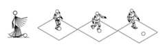
도 1은 본 발명의 일실시예에 의한 로봇의 외관도이다.1 is an external view of a robot according to an embodiment of the present invention.
도 1에 도시한 바와 같이, 로봇(100)은 인간과 마찬가지로 두 개의 다리(110R,110L)에 의해 직립 이동하는 이족 보행 로봇으로, 몸통(120)과, 몸통(120)의 상부에 두 개의 팔(130R,130L)과 머리(140)를 구비하며, 두 개의 다리(110R,110L)와 팔(130R,130L) 선단에는 각각 발(111R,111L)과, 핸드(131R,131L)를 구비한다.As shown in FIG. 1, the
참조 부호에서 R과 L은 로봇(100)의 오른쪽(Right)과 왼쪽(left)을 나타낸다.In the reference numerals R and L denote the right side and the left side of the
도 2는 도 1에 나타낸 로봇의 주요 관절 구조를 나타낸 도면이다.Fig. 2 is a view showing a main joint structure of the robot shown in Fig. 1. Fig.
도 2에 도시한 바와 같이, 머리(140)를 지지하는 목 관절은 목 관절 롤축(2),목 관절 피치축(3) 및 목 관절 요우축(4)으로 구성되어 x축(roll axis)과 y축(pitch axis)과 z축(yaw axis)으로 움직임이 가능하다.2, the neck joint supporting the
두 개의 팔(130R,130L)은 로봇(100)의 어깨, 팔꿈치, 손목에 해당하는 부분이 회전할 수 있도록 어깨 관절, 팔꿈치 관절 및 손목 관절을 각각 구비한다.The two
두 개의 팔(130R,130L)의 어깨 관절은 어깨 관절 롤축(8R,8L)과, 어깨 관절 피치축(9R,9L)과, 어깨 관절 요우축(10R,10L)로 구성되어 x축(roll axis)과 y축(pitch axis)과 z축(yaw axis)으로 움직임이 가능하다.The shoulder joints of the two
두 개의 팔(130R,130L)의 팔꿈치 관절은 팔꿈치 관절 피치축(11R,11L)과 팔꿈치 관절 요우축(12R,12L)으로 구성되어 y축(pitch axis)과 z축(yaw axis)으로 움직임이 가능하다.The elbow joints of the two
두 개의 팔(130R,130L)의 손목 관절은 손목 관절 롤축(13R,13L)과, 손목 관절 피치축(14R,14L)과, 손목 관절 요우축(15R,15L)으로 구성되어 x축(roll axis)과 y축(pitch axis)과 z축(yaw axis)으로 움직임이 가능하다.The wrist joints of the two
몸통(120)은 몸체부 롤축(5)과, 몸체부 피치축(6)과, 몸체부 요우축(7)으로 구성되어 x축(roll axis)과 y축(pitch axis)과 z축(yaw axis)으로 움직임이 가능하다.The
두 개의 다리(110R,110L)는 다리 관절 롤축(16R,16L)과, 다리 관절 피치축(17R,17L)과, 다리 관절 요우축(18R,18L)으로 구성되어 x축(roll axis)과 y축(pitch axis)과 z축(yaw axis)으로 움직임이 가능하며, 무릎 관절 피치축(19R,19L)으로 구성되어 y축(pitch axis)으로 움직임이 가능하며, 발목 관절 롤축(20R,20L)과, 발목 관절 피치축(21R,21L)으로 구성되어 x축(roll axis)과 y축(pitch axis)방향으로 움직임이 가능하다.The two
한편, 상술한 인간형 로봇(100)이 갖는 각 자유도는 실제로는 작동기를 이용하여 장착된다. 외관상에서 여분의 팽창을 배제하여 인간의 자연체 형상에 근사시키고, 불안정 구조체에 대해 자세 제어를 행하는 등의 요구에 기인하면 작동기는 소형 또는 경량인 것이 바람직하다.On the other hand, each degree of freedom of the
도 3은 본 발명의 일실시예에 의한 로봇의 제어블록도이다.3 is a control block diagram of a robot according to an embodiment of the present invention.
도 3에 도시한 바와 같이, 로봇(100)은 사용자에 의해 모션 커맨드 등이 입력되는 입력부(200)와, 입력된 모션 커맨드를 해석하고 로봇 관절 궤도의 시작점과 종점 간의 중간경로계획을 생성하는 커맨드 해석부(214) 및 커맨드 해석부(214)에 연결되어 모션 명령을 생성하는 커맨드 생성부(218)를 포함하는 제어부(210)와, 제어부(210)의 제어에 의해 로봇(100)의 각 관절을 구동하는 구동부(220)를 포함한다.3, the
제어부(210)는 모션(예를 들면, 공차기 또는 공던지기)의 시작 자세와 마지막 자세가 주어지면 엔드 이펙터(end-effecter, 예를 들면, 손끝과 발끝)가 최대속도가 나올 수 있도록 관절 트라젝터리(joint trajectory)를 최적화한다. 관절 트라젝터리를 최적화한다는 것은 엔드 이펙터가 최대 속도가 나올 수 있도록 각 관절의 각도, 속도 및 가속도를 최적화하는 것을 의미한다. 이를 위해, 제어부(210)는 다음과 같은 동작을 한다.The
첫째로, 제어부(210)는 모션의 시작시간과 종료시간이 임의로 주어지면, 모션의 시작시간 및 종료시간에 따라 각 관절 및 무게 중심(CoG : Center of Gravity))의 트라젝터리(trajectory)를 형성한다. 트라젝터리를 형성하면 시간에 따른 로봇(100)의 관절 각도, 속도 및 가속도값을 추출할 수 있으므로, 로봇(100)은 추출된 관절 각도, 속도 및 가속도값에 따라 모션을 수행할 수 있게 된다. 한편, 제어부(210)는 벨타입(bell type) 속도 프로파일을 작업공간 또는 관절공간 상의 속도 프로파일로 사용하며, 관절 각각의 속도파일을 시작시간과 종료시간으로 매개화해서 각 관절의 최적제어타이밍을 결정할 수 있다. 벨타입 속도 프로파일은 프로파일의 형태를 벨 형태로 하여 시간에 따른 속도변화를 나타내는 프로파일이다. 트라젝터리 형성에 대해서는 도 4에서 구체적으로 후술하기로 한다.First, when the start time and the end time of the motion are arbitrarily given, the
둘째로, 제어부(210)는 모션 수행 시 엔드 이펙터의 속도를 최대화하기 위해 다음과 같은 식 1로 제한조건이 있는 목적함수의 최소값(Jmin)을 추출한다.Second, the
(식 1)(Equation 1)

= Jmin= Jmin
이하, 식 1의 미지수에 대해 순차적으로 설명한다.(w1 내지 w4는 상수)Hereinafter, the unknowns in
"
(식 2)(Equation 2)

여기서, "VEnd_x,max"는 엔드 이펙터의 x방향의 최대 속도를 의미하고, "VEnd_y,max"는 엔드 이펙터의 y방향의 최대 속도를 의미하며, "VEnd_z,max"는 엔드 이펙터의 z방향의 최대 속도를 의미하며, "c"는 모션의 방향의 높이를 결정하는 상수이다. 한편, "
"
(식 3)(Equation 3)

여기서,


"
(식 4)(Equation 4)

여기서,


(식 5)(Equation 5)

여기서,


(식 6)(Equation 6)

여기서, L과 P는 회전모멘텀 및 선형모멘텀으로 로봇 전체 무게 중심의 위치인


"
(식 7)(Equation 7)

여기서,


(식 8)(Expression 8)

(식 9)(Equation 9)

(식 10)(Equation 10)

여기서, M은 로봇(100)의 전체 무게를 의미하고, g는 중력가속도를 의미하며, Cx, Cy 및 Cz는 무게중심(Center of Gravity)의 x성분, y성분 및 z성분을 의미하며, Px, Py 및 Pz는 선형모멘텀의 x성분, y성분 및 z성분을 의미하며, Lx, Ly 및 Lz는 회전모멘텀의 x성분, y성분 및 z성분을 의미한다. 한편,


제어부(210)는 식 1의 목적 함수값을 계산하고, 최적화를 위한 수렴조건을 만족하면 최적화 반복(iteration) 동작을 중지한다. 이 때, 목적함수의 값의 변화량이 임의의 값 이하인 경우에 최적함수 수렴조건이 만족된다.The
도 4a는 본 발명의 일실시예에 의한 로봇의 모션을 최적화시키기 전 팔 관절의 속도 프로파일을 벨 타입으로 도시한 그래프이며, 도 4b는 본 발명의 일실시예에 의한 로봇의 모션을 최적화시킨 후 팔 관절의 속도 프로파일을 벨 타입으로 도시한 그래프이다.FIG. 4A is a graph showing a bell type velocity profile of the arm joint before optimizing motion of the robot according to an embodiment of the present invention. FIG. 4B is a graph illustrating the motion profile of the robot after optimizing the motion of the robot according to an embodiment of the present invention The graph shows the velocity profile of the arm joint in a bell type.
로봇(100)의 공 던지기 모션의 경우, 로봇(100)의 오른쪽 어깨 관절의 롤축(8R)과, 어깨 관절 피치축(9R)과, 어깨 관절 요우축(10R)을 사용하고, 로봇의 팔꿈치 관절 요우축(12R)과, 팔꿈치 관절 피치축(11R)을 사용하며, 손목 관절 롤축(13R)과, 손목 관절 피치축(14R)과, 손목 관절 요우축(15R)을 사용하여 공을 원하는 방향으로 던지게 된다.A shoulder
도 4a에 도시한 바와 같이, 제어부(210)는 던지기 모션을 수행하는데 필요한 팔에 대한 관절의 속도 프로파일을 각각의 모션의 시작시간과 종료시간을 나타내는 매개변수로 매개화하여 나타낼 수 있다. 도 4a는 로봇의 모션을 최적화하기 전의 팔 관절의 프로파일로서 각 관절의 시작시간 및 종료시간이 동일하고, 각 관절의 각도, 속도 및 가속도의 최고값이 다른 것을 알 수 있다. 한편, 벨타입의 속도 프로파일에 대한 함수(g'(t))를 미분하면 가속도 프로파일에 대한 함수(g"(t))를 생성할 수 있으며, 속도 프로파일에 대한 함수를 적분하면 관절 각도에 대한 프로파일에 대한 함수(g(t))를 생성할 수 있다.As shown in FIG. 4A, the
도 4b에 도시한 바와 같이, 제어부(210)는 던지기 모션을 수행하는데 필요한 팔에 대한 관절의 속도 프로파일을 최적화하여 각각의 모션의 시작시간과 종료시간을 타내는 매개변수로 매개화할 수 있다. 도 4b는 로봇(100)의 최대 동적 수행 능력을 끌어내기 위해 모션을 최적화한 속도 프로파일로서, 로봇(100)이 던지기 모션을 수행할 때, 무거운 어깨 관절부터 엔드 이펙터 즉, 손 끝까지 에너지 손실을 극소화한 채 에너지 및 모멘텀 전이가 이루어져 손끝에서 적절한 타이밍에 최대 속도를 달성할 수 있게 된다.As shown in FIG. 4B, the
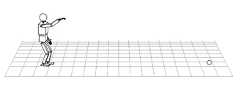
도 5a는 본 발명의 일실시예에 의한 로봇 관절의 최적화 기법을 적용하기 전에 던지기 모션을 도시한 것이며, 도 5b는 본 발명의 일실시예에 의한 로봇 관절의 최적화 기법을 적용한 후 던지기 모션을 도시한 것이다.FIG. 5A illustrates casting motion before applying a robot joint optimization technique according to an embodiment of the present invention, FIG. 5B illustrates a casting motion after applying a robot joint optimization technique according to an embodiment of the present invention, It is.
도 5a 및 도 5b에 도시한 바와 같이, 로봇(100)의 관절 제어 입력 타이밍이 최적화되면 제한된 사이즈의 엑츄에이터를 구비한 로봇(100)의 최대 동적 수행 능력을 끌어내어 공을 더 멀리 던질 수 있게 된다.As shown in FIGS. 5A and 5B, when the joint control input timing of the
도 6a 및 도 6b는 본 발명의 일실시예에 의한 로봇의 최적화된 모션 수행 동작을 도시한 도면이다.FIGS. 6A and 6B are diagrams showing an optimized motion-performing operation of the robot according to an embodiment of the present invention.
도 6a에 도시한 바와 같이, 로봇(100)이 공 던지기 동작을 수행하는 경우, 로봇(100)이 최대 속도로 공을 던지기 위해서는 어깨 관절(8,9,10)이 움직이면서 팔꿈치 관절(11,12)이 움직인 후 손목관절(13,14,15)이 순차적으로 동작하여 최적화된 타이밍에 모터 구동이 이루어져야 한다. 모션 수행을 위한 각 관절이 최적화된 트라젝터리에 따라 순차적으로 동작하면 어깨부터 손끝까지 에너지 손실을 극소화한 채 에너지 및 모멘텀 전이가 이루어져 엔드이펙터(예를 들면, 손끝)에서 적절한 타이밍에 최대 속도를 달성할 수 있게 된다.6A, when the
도 6b에 도시한 바와 같이, 로봇(100)이 공 차기 동작을 수행하는 경우, 로봇(100)이 최대 속도로 공을 차기 위해서는 다리 관절(16,17,18)이 움직이면서 무릎 관절(19)이 움직인 후 발목 관절(20,21)이 순차적으로 동작하여 최적화된 타이밍으로 모터를 구동시켜야 한다.6B, when the
도 7은 본 발명의 일실시예에 의한 로봇의 제어흐름도이다.7 is a control flowchart of a robot according to an embodiment of the present invention.
도 7에 도시한 바와 같이, 제어부(210)는 모션을 수행하기 위한 관절과 로봇(100) 무게 중심 속도 프로파일을 시작 시간과 종료 시간을 나타내는 매개변수로 매개화한다.(s10)7, the
다음으로, 제어부(210)는 임의의 초기값에 의한 트라젝터리를 형성한다. 즉, 모션의 시작시간 및 종료시간이 임의적으로 설정되면, 설정된 시작시간 및 종료시간에 따라 각 관절 및 무게 중심의 트라젝터리를 형성한다.(s20)Next, the
다음으로, 제어부(210)는 제한조건이 있는 목적함수의 값을 계산한다. 제한조건이 있는 목적함수는 다음과 같은 식 1을 의미한다.Next, the
(식 1)(Equation 1)

= Jmin= Jmin
여기서,


다음으로, 제어부(210)는 목적함수 계산 루틴의 수렴조건이 만족되는지 확인한다. 수렴조건은 제한조건이 있는 목적함수의 값이 이전 루틴에서 구해진 목적함수의 값과 일정 크기 이하로 차이나는 경우에 만족하게 된다.(s40)Next, the
다음으로, 제어부(210)는 목적함수 계산 루틴의 수렴조건이 만족되는 것으로 확인되면 제한조건이 있는 목적함수의 값이 최소값이 되게 하는 시작시간(t0) 및 종료시간(tf)을 확인한다.(s50)Next, when it is determined that the convergence condition of the objective function calculation routine is satisfied, the
다음으로, 제어부(210)는 제한조건이 있는 목적함수의 값이 최소값이 되게 하는 시작시간(t0) 및 종료시간(tf)으로 형성된 트라젝터리를 모션을 형성하는데 필요한 관절 및 무게중심의 속도 프로파일로 선정한다.(s60)Next, the
한편, 상술한 s40단계에서 수렴 조건이 만족되지 않은 것으로 확인되면 s20단계로 피드백하여 다른 초기값에 의한 트라젝터리를 형성하여 목적함수의 값을 계산하게 된다.(s70)If it is determined in step s40 that the convergence condition is not satisfied, the flow returns to step s20 to form a trajectory based on another initial value to calculate the value of the objective function. (S70)
도 1은 본 발명의 일실시예에 의한 로봇의 외관도Fig. 1 is a perspective view of a robot according to an embodiment of the present invention.
도 2는 도 1에 나타낸 로봇의 주요 관절 구조를 나타낸 도면2 is a view showing a main joint structure of the robot shown in Fig. 1
도 3은 본 발명의 일실시예에 의한 로봇의 제어블록도3 is a block diagram of a robot according to an embodiment of the present invention.
도 4a는 본 발명의 일실시예에 의한 로봇의 모션을 최적화시키기 전 팔 관절의 속도 프로파일을 벨 타입으로 도시한 그래프FIG. 4A is a graph showing the velocity profile of the arm joint in bell type before optimizing the motion of the robot according to an embodiment of the present invention
도 4b는 본 발명의 일실시예에 의한 로봇의 모션을 최적화시킨 후 팔 관절의 속도 프로파일을 벨 타입으로 도시한 그래프FIG. 4B is a graph showing the velocity profile of the arm joint as a bell type after optimizing the motion of the robot according to an embodiment of the present invention.
도 5a는 본 발명의 일실시예에 의한 로봇 관절의 최적화 기법을 적용하기 전에 던지기 모션을 도시한 도면FIG. 5A is a diagram illustrating throwing motion before applying the robot joint optimization technique according to an embodiment of the present invention. FIG.
도 5b는 본 발명의 일실시예에 의한 로봇 관절의 최적화 기법을 적용한 후 던지기 모션을 도시한 도면FIG. 5B is a view showing a throwing motion after applying a robot joint optimization technique according to an embodiment of the present invention
도 6은 본 발명의 일실시예에 의한 로봇의 제어흐름도FIG. 6 is a flowchart showing a control flow of a robot according to an embodiment of the present invention.
Claims (14)
Translated fromKorean


Priority Applications (2)
| Application Number | Priority Date | Filing Date | Title |
|---|---|---|---|
| KR1020090104625AKR101691940B1 (en) | 2009-10-30 | 2009-10-30 | Robot and control method thereof |
| US12/926,078US9037292B2 (en) | 2009-10-30 | 2010-10-25 | Robot and control method of optimizing robot motion performance thereof |
Applications Claiming Priority (1)
| Application Number | Priority Date | Filing Date | Title |
|---|---|---|---|
| KR1020090104625AKR101691940B1 (en) | 2009-10-30 | 2009-10-30 | Robot and control method thereof |
Publications (2)
| Publication Number | Publication Date |
|---|---|
| KR20110047842A KR20110047842A (en) | 2011-05-09 |
| KR101691940B1true KR101691940B1 (en) | 2017-01-02 |
Family
ID=43926255
Family Applications (1)
| Application Number | Title | Priority Date | Filing Date |
|---|---|---|---|
| KR1020090104625AActiveKR101691940B1 (en) | 2009-10-30 | 2009-10-30 | Robot and control method thereof |
Country Status (2)
| Country | Link |
|---|---|
| US (1) | US9037292B2 (en) |
| KR (1) | KR101691940B1 (en) |
Families Citing this family (8)
| Publication number | Priority date | Publication date | Assignee | Title |
|---|---|---|---|---|
| GB2523831B (en)* | 2014-03-07 | 2020-09-30 | Cmr Surgical Ltd | Surgical arm |
| EP3061576B1 (en)* | 2015-02-26 | 2021-03-31 | Siemens Aktiengesellschaft | Method for optimizing a movement profile, computer program, control device and technical system |
| JP6421683B2 (en)* | 2015-04-14 | 2018-11-14 | トヨタ自動車株式会社 | Optimal control device, optimal control method, and optimal control program |
| GB2538497B (en) | 2015-05-14 | 2020-10-28 | Cmr Surgical Ltd | Torque sensing in a surgical robotic wrist |
| KR102543212B1 (en) | 2015-10-26 | 2023-06-14 | (주)한화 | System and method for controlling robot |
| US10248085B2 (en)* | 2016-10-13 | 2019-04-02 | Disney Enterprises, Inc. | Computational design of robots from high-level task specifications |
| US12097619B2 (en)* | 2022-09-26 | 2024-09-24 | Fanuc Corporation | Predictive control method for torque-rate control and vibration suppression |
| CN119927896A (en)* | 2024-12-03 | 2025-05-06 | 北京华航唯实机器人科技股份有限公司 | Method and device for time statistical analysis of motion mechanisms based on one-way digital twins |
Citations (1)
| Publication number | Priority date | Publication date | Assignee | Title |
|---|---|---|---|---|
| KR100818059B1 (en)* | 2006-10-09 | 2008-03-31 | 한국과학기술연구원 | How to Control the Reproduction of Human Arm Behavior in Humanoid Robots |
Family Cites Families (15)
| Publication number | Priority date | Publication date | Assignee | Title |
|---|---|---|---|---|
| US4829219A (en)* | 1986-11-20 | 1989-05-09 | Unimation Inc. | Multiaxis robot having improved motion control through variable acceleration/deceleration profiling |
| JP2676397B2 (en)* | 1989-01-05 | 1997-11-12 | 株式会社エイ・ティ・アール視聴覚機構研究所 | Dynamic trajectory generation method for dynamic system |
| CA2081519C (en)* | 1992-10-27 | 2000-09-05 | The University Of Toronto | Parametric control device |
| US5499320A (en)* | 1993-03-24 | 1996-03-12 | The United States Of America As Represented By The Administrator Of The National Aeronautics And Space Administration | Extended task space control for robotic manipulators |
| US6224312B1 (en)* | 1996-11-18 | 2001-05-01 | Applied Materials, Inc. | Optimal trajectory robot motion |
| KR20000066834A (en)* | 1999-04-21 | 2000-11-15 | 장병우 | Method for controlling acceleration and deceleration of servo motor |
| WO2003007129A2 (en)* | 2001-07-13 | 2003-01-23 | Broks Automation, Inc. | Trajectory planning and motion control strategies for a planar three-degree-of-freedom robotic arm |
| US9144360B2 (en)* | 2005-12-02 | 2015-09-29 | Irobot Corporation | Autonomous coverage robot navigation system |
| JP4591419B2 (en)* | 2006-07-18 | 2010-12-01 | トヨタ自動車株式会社 | Robot and its control method |
| JP4692443B2 (en)* | 2006-09-06 | 2011-06-01 | トヨタ自動車株式会社 | Legged robot |
| KR100856824B1 (en)* | 2007-07-23 | 2008-09-05 | 재단법인서울대학교산학협력재단 | Character simulation method and system |
| JP4440956B2 (en)* | 2007-09-12 | 2010-03-24 | トヨタ自動車株式会社 | Legged robot and control method thereof |
| JP4392037B2 (en)* | 2007-09-12 | 2009-12-24 | トヨタ自動車株式会社 | Legged robot and control method thereof |
| KR100995933B1 (en)* | 2008-09-01 | 2010-11-22 | 한국과학기술연구원 | Robot Motion Control Based on Evolutionary Algorithm and Imitation Learning |
| KR20110074520A (en)* | 2008-09-04 | 2011-06-30 | 아이워크, 아이엔씨. | Hybrid Terrain-Adaptive Prosthetic Systems |
- 2009
- 2009-10-30KRKR1020090104625Apatent/KR101691940B1/enactiveActive
- 2010
- 2010-10-25USUS12/926,078patent/US9037292B2/enactiveActive
Patent Citations (1)
| Publication number | Priority date | Publication date | Assignee | Title |
|---|---|---|---|---|
| KR100818059B1 (en)* | 2006-10-09 | 2008-03-31 | 한국과학기술연구원 | How to Control the Reproduction of Human Arm Behavior in Humanoid Robots |
Non-Patent Citations (1)
| Title |
|---|
| 2004 IEEE International Conference on Systems, Man and Cybernetics 722-727 (2004. 10.)* |
Also Published As
| Publication number | Publication date |
|---|---|
| US20110106303A1 (en) | 2011-05-05 |
| KR20110047842A (en) | 2011-05-09 |
| US9037292B2 (en) | 2015-05-19 |
Similar Documents
| Publication | Publication Date | Title |
|---|---|---|
| KR101691940B1 (en) | Robot and control method thereof | |
| JP3824608B2 (en) | Legged mobile robot and its motion control method | |
| KR100687461B1 (en) | Robot and Joint Device for Robot | |
| KR100977348B1 (en) | Motion control device and motion control method for legged mobile robot and robot device | |
| KR101004820B1 (en) | Mobile device, control method of mobile device, robot device, motion control method of robot device | |
| JP3615702B2 (en) | Motion control device and motion control method for legged mobile robot, and legged mobile robot | |
| US7339340B2 (en) | Control system and related method for multi-limbed, multi-legged robot | |
| JP3555107B2 (en) | Legged mobile robot and operation control method for legged mobile robot | |
| KR100837988B1 (en) | Motion control device and motion control method for each mobile robot, and robot device | |
| Ott et al. | Development of a biped robot with torque controlled joints | |
| Dip et al. | Genetic algorithm-based optimal bipedal walking gait synthesis considering tradeoff between stability margin and speed | |
| CN108897220B (en) | Self-adaptive stable balance control method and system and biped humanoid robot | |
| KR20110047847A (en) | Humanoid robot and its control method | |
| JP4475708B2 (en) | Legged mobile robot and its motion control method | |
| JP4660870B2 (en) | Legged mobile robot and control method thereof | |
| JP3674779B2 (en) | Motion control device and motion control method for legged mobile robot, and robot device | |
| Verrelst et al. | Motion generation and control for the pneumatic biped" lucy" | |
| JP4770990B2 (en) | Legged mobile robot and control method thereof | |
| Wang et al. | A new bionic structure of inspection robot for high voltage transmission line | |
| Hu et al. | Study of series-parallel mechanism used in legs of biped robot | |
| JP2004181613A (en) | Robot device, device and method for controlling operation of legged locomotion robot, sensor system for legged locomotion robot, and moving body device | |
| Tiejun et al. | The development of a mobile humanoid robot with varying joint stiffness waist | |
| JP3568527B2 (en) | Mobile device | |
| JP2004025434A (en) | Motion control device and method for leg-type moving robot, and robot device | |
| Perkins et al. | Heuristic control of bipedal running: steady-state and accelerated |
Legal Events
| Date | Code | Title | Description |
|---|---|---|---|
| PA0109 | Patent application | Patent event code:PA01091R01D Comment text:Patent Application Patent event date:20091030 | |
| PG1501 | Laying open of application | ||
| A201 | Request for examination | ||
| PA0201 | Request for examination | Patent event code:PA02012R01D Patent event date:20141010 Comment text:Request for Examination of Application Patent event code:PA02011R01I Patent event date:20091030 Comment text:Patent Application | |
| E902 | Notification of reason for refusal | ||
| PE0902 | Notice of grounds for rejection | Comment text:Notification of reason for refusal Patent event date:20160212 Patent event code:PE09021S01D | |
| AMND | Amendment | ||
| E601 | Decision to refuse application | ||
| PE0601 | Decision on rejection of patent | Patent event date:20160805 Comment text:Decision to Refuse Application Patent event code:PE06012S01D Patent event date:20160212 Comment text:Notification of reason for refusal Patent event code:PE06011S01I | |
| AMND | Amendment | ||
| PX0901 | Re-examination | Patent event code:PX09011S01I Patent event date:20160805 Comment text:Decision to Refuse Application Patent event code:PX09012R01I Patent event date:20160412 Comment text:Amendment to Specification, etc. | |
| PX0701 | Decision of registration after re-examination | Patent event date:20160929 Comment text:Decision to Grant Registration Patent event code:PX07013S01D Patent event date:20160905 Comment text:Amendment to Specification, etc. Patent event code:PX07012R01I Patent event date:20160805 Comment text:Decision to Refuse Application Patent event code:PX07011S01I Patent event date:20160412 Comment text:Amendment to Specification, etc. Patent event code:PX07012R01I | |
| X701 | Decision to grant (after re-examination) | ||
| GRNT | Written decision to grant | ||
| PR0701 | Registration of establishment | Comment text:Registration of Establishment Patent event date:20161227 Patent event code:PR07011E01D | |
| PR1002 | Payment of registration fee | Payment date:20161228 End annual number:3 Start annual number:1 | |
| PG1601 | Publication of registration | ||
| PR1001 | Payment of annual fee | Payment date:20211115 Start annual number:6 End annual number:6 | |
| PR1001 | Payment of annual fee | Payment date:20221114 Start annual number:7 End annual number:7 | |
| PR1001 | Payment of annual fee | Payment date:20241114 Start annual number:9 End annual number:9 |