KR101691666B1 - Inter-Frequency Measurement Method - Google Patents
Inter-Frequency Measurement MethodDownload PDFInfo
- Publication number
- KR101691666B1 KR101691666B1KR1020100117135AKR20100117135AKR101691666B1KR 101691666 B1KR101691666 B1KR 101691666B1KR 1020100117135 AKR1020100117135 AKR 1020100117135AKR 20100117135 AKR20100117135 AKR 20100117135AKR 101691666 B1KR101691666 B1KR 101691666B1
- Authority
- KR
- South Korea
- Prior art keywords
- frequency
- antenna
- measurement
- service
- receiver
- Prior art date
- Legal status (The legal status is an assumption and is not a legal conclusion. Google has not performed a legal analysis and makes no representation as to the accuracy of the status listed.)
- Expired - Fee Related
Links
Images


Classifications
- H—ELECTRICITY
- H04—ELECTRIC COMMUNICATION TECHNIQUE
- H04B—TRANSMISSION
- H04B7/00—Radio transmission systems, i.e. using radiation field
- H04B7/02—Diversity systems; Multi-antenna system, i.e. transmission or reception using multiple antennas
- H04B7/04—Diversity systems; Multi-antenna system, i.e. transmission or reception using multiple antennas using two or more spaced independent antennas
- H—ELECTRICITY
- H04—ELECTRIC COMMUNICATION TECHNIQUE
- H04B—TRANSMISSION
- H04B17/00—Monitoring; Testing
- H04B17/30—Monitoring; Testing of propagation channels
- H04B17/309—Measuring or estimating channel quality parameters
- H—ELECTRICITY
- H04—ELECTRIC COMMUNICATION TECHNIQUE
- H04B—TRANSMISSION
- H04B7/00—Radio transmission systems, i.e. using radiation field
- H04B7/02—Diversity systems; Multi-antenna system, i.e. transmission or reception using multiple antennas
- H04B7/04—Diversity systems; Multi-antenna system, i.e. transmission or reception using multiple antennas using two or more spaced independent antennas
- H04B7/0413—MIMO systems
- H—ELECTRICITY
- H04—ELECTRIC COMMUNICATION TECHNIQUE
- H04L—TRANSMISSION OF DIGITAL INFORMATION, e.g. TELEGRAPHIC COMMUNICATION
- H04L25/00—Baseband systems
- H04L25/02—Details ; arrangements for supplying electrical power along data transmission lines
- H04L25/0202—Channel estimation
- H04L25/0204—Channel estimation of multiple channels
Landscapes
- Engineering & Computer Science (AREA)
- Computer Networks & Wireless Communication (AREA)
- Signal Processing (AREA)
- Quality & Reliability (AREA)
- Physics & Mathematics (AREA)
- Electromagnetism (AREA)
- Power Engineering (AREA)
- Radio Transmission System (AREA)
- Mobile Radio Communication Systems (AREA)
Abstract
Translated fromKoreanDescription
Translated fromKorean본 발명은 인터 프리퀀시(Inter-Frequency) 측정 방법에 관한 것이다.The present invention relates to an inter-frequency measurement method.
WCDMA(Wideband Code Division Multiple Access) 무선 접속(radio access) 기술을 기반으로 하는 3GPP(3rd Generation Partnership Project) 무선 통신 시스템은 전세계에서 광범위하게 전개되고 있다. WCDMA의 첫 번째 진화 단계로 정의할 수 있는 HSDPA(High Speed Downlink Packet Access)는 중기적인(mid-term) 미래에서 높은 경쟁력을 가지는 무선 접속 기술을 3GPP에 제공한다.A 3rd Generation Partnership Project (3GPP) wireless communication system based on Wideband Code Division Multiple Access (WCDMA) radio access technology is widely deployed all over the world. HSDPA (High Speed Downlink Packet Access), which can be defined as the first evolutionary phase of WCDMA, provides 3GPP with highly competitive wireless access technology in the mid-term future.
장기적인 미래에서 높은 경쟁력을 제공하기 위한 것으로서 E-UMTS가 있다. E-UMTS는 기존의 WCDMA UMTS에서 진화한 시스템으로 3GPP에서 표준화 작업을 진행하고 있다. E-UMTS는 LTE(Long Term Evolution) 시스템이라 불리기도 한다. UMTS 및 E-UMTS의 기술 규격(technical specification)의 상세한 내용은 각각 "3rd Generation Partnership Project; Technical Specification Group Radio Access Network"의 Release 7과 Release 8을 참조할 수 있다.There is E-UMTS to provide high competitiveness in the long term future. E-UMTS is a system that evolved from existing WCDMA UMTS and is being standardized in 3GPP. E-UMTS is also called Long Term Evolution (LTE) system. For details of the technical specifications of UMTS and E-UMTS, refer to Release 7 and Release 8 of "3rd Generation Partnership Project (Technical Specification Group Radio Access Network)" respectively.
E-UMTS는 크게 단말(User Equipment; UE)과 기지국, 네트워크(E-UTRAN)의 종단에 위치하여 외부 네트워크와 연결되는 접속 게이트웨이(Access Gateway; AG)로 구성된다. 통상적으로 기지국은 브로드캐스트 서비스, 멀티캐스트 서비스 및/또는 유니캐스트 서비스를 위해 다중 데이터 스트림을 동시 송신할 수 있다. LTE 시스템에서는 다양한 서비스를 하향 전송하기 위해 직교주파수 분할 다중화 방식(Orthogonal frequency divisional multiplexing; OFDM)과 다중안테나(Multi-input Multi-out; MIMO)를 사용하고 있다.The E-UMTS is largely composed of an Access Gateway (AG) located at the end of a User Equipment (UE), a base station and a network (E-UTRAN) and connected to an external network. Typically, a base station may simultaneously transmit multiple data streams for broadcast services, multicast services, and / or unicast services. In the LTE system, Orthogonal Frequency Divisional Multiplexing (OFDM) and Multi-input Multi-out (MIMO) are used to downlink various services.
OFDM은 고속 데이터 하향링크 접속 시스템을 대표한다. OFDM의 이점은 할당된 전체 스펙트럼이 모든 기지국에의해 사용될 수 있는 높은 스펙트럼 효율성이다. OFDM 변조에서 전송 대역은 주파수 영역에서 복수의 직교하는 부반송파로 나누어지고, 시간 영역에서 복수의 심볼로 나누어진다. OFDM은 전송 대역을 복수의 부반송파로 분할하므로 부반송파 당 대역폭은 감소하고 반송파당 변조 시간은 증가한다. 상기 복수의 부반송파가 병렬로 전송되므로, 특정 부반송파의 디지털 데이터 또는 심볼 전송률은 단일 반송파보다 낮아진다.OFDM represents a high-speed data downlink access system. The advantage of OFDM is the high spectral efficiency that the entire spectrum allocated can be used by all base stations. In OFDM modulation, a transmission band is divided into a plurality of orthogonal subcarriers in the frequency domain and a plurality of symbols in the time domain. Since OFDM divides the transmission band into a plurality of subcarriers, the bandwidth per subcarrier decreases and the modulation time per carrier increases. Since the plurality of subcarriers are transmitted in parallel, the digital data or symbol transmission rate of a specific subcarrier is lower than that of a single carrier.
다중안테나(Multiple input mulple output; MIMO) 시스템은 복수의 송수신 안테나를 사용하는 통신 시스템이다.A multiple input multiple output (MIMO) system is a communication system using a plurality of transmit and receive antennas.
MIMO 시스템은 송수신 안테나의 수가 증가함에 따라 추가적인 주파수 대역폭의 증가없이 채널 용량을 선형적으로 증가시킬 수 있다. MIMO 기술은 다양한 채널 경로를 통과한 심볼을 이용하여 전송 신뢰도를 높일 수 있는 공간 다이버시티(spatial diversity) 방식과, 복수의 송신 안테나를 사용하여 각 안테나가 동시에 별개의 데이터 스트림을 전송하여 전송 레이트를 증가시키는 공간 멀티플렉싱(spatial multiplexing) 방식이 있다.The MIMO system can linearly increase the channel capacity without increasing the additional frequency bandwidth as the number of transmit and receive antennas increases. The MIMO technique uses a spatial diversity scheme that can increase transmission reliability using symbols that have passed through various channel paths and a scheme in which each antenna simultaneously transmits a separate data stream using a plurality of transmit antennas, And a spatial multiplexing scheme for increasing the size of the network.
MIMO 기술은 송신단에서 채널 정보를 알고 있는지 여부에 따라 크게 개-루프(open-loop) MIMO 기술과 폐-루프(closed-loop) MIMO 기술로 분류될 수 있다. 상기 개-루프 MIMO 기술에서 송신단은 채널 정보를 알고 있지않다. 상기 개-루프 MIMO 기술의 예로는 PARC(per antenna rate conrol), PCBRC(per common basis rate control), BLAST, STTC, 랜덤 빔포밍(random beamforming) 등이 있다. 반면, 상기 폐-루프 MIMO 기술에서 송신단은 채널 정보를 알고 있다. 폐-루프 MIMO 시스템의 성능은 상기 채널 정보를 얼마나 정확하게 알고 있느냐에 따라 좌우된다. 상기 폐-루프 MIMO 기술의 예로는 PSRC(per stream rate control), TxAA 등이 있다.MIMO technology can be roughly divided into open-loop MIMO technology and closed-loop MIMO technology depending on whether channel information is known at a transmitter. In the open-loop MIMO technique, the transmitter does not know the channel information. Examples of the open-loop MIMO technique include per antenna rate control (PARC), per common basis rate control (PCBRC), BLAST, STTC, and random beamforming. On the other hand, in the closed-loop MIMO technique, the transmitter knows the channel information. The performance of the closed-loop MIMO system depends on how accurately the channel information is known. Examples of the closed-loop MIMO technique include per-stream rate control (PSRC), TxAA, and the like.
채널 정보란 복수의 송신 안테나 및 복수의 수신 안테나 간의 무선 채널 정보(예, 감쇄, 위상 편이 또는 시간지연 등)를 의미한다. MIMO 시스템에서는, 복수의 송수신 안테나 조합에 의한 다양한 스트림 경로가 존재하고, 다중 경로 시간 딜레이로 인해 채널 상태가 시간에 따라 시간/주파수 영역에서 불규칙하게 변하는 페이딩 특성을 갖는다. 따라서, 송신단은 채널 추정을 통하여 채널 정보를 산출한다. 채널 추정이란 왜곡된 전송 신호를 복원하기 위해 필요한 채널 정보를 추정하는 것이다. 예를 들어, 채널 추정은 반송파의 크기 및 기준 위상을 추정하는 것을 말한다. 즉, 채널 추정은 무선구간 또는 무선채널의 주파수 응답을 추정하는 것이다.Channel information means radio channel information (e.g., attenuation, phase shift, or time delay) between a plurality of transmission antennas and a plurality of reception antennas. In the MIMO system, there are various stream paths by a plurality of transmission / reception antenna combinations, and the channel state has a fading characteristic that varies irregularly in the time / frequency domain due to multipath time delay. Therefore, the transmitting end calculates channel information through channel estimation. The channel estimation is to estimate channel information necessary for restoring a distorted transmission signal. For example, channel estimation refers to estimating the size and reference phase of a carrier wave. That is, the channel estimation is to estimate the frequency response of the radio section or the radio channel.
채널 추정 방법으로는, 2차원 채널 추정기를 사용하여 몇 개 기지국의 참조 신호(Reference Signal; RS)를 바탕으로 기준값을 추정하는 방법이 있다. 이때, RS란 반송파 위상 동기화 및 기지국 정보 획득 등에 도움이 되도록 하기 위해, 실제로 데이터를 가지지는 않지만 높은 출력을 갖는 심볼을 말한다. 송신측 및 수신측은 이와 같은 RS를 이용하여 채널 추정을 수행할 수 있다. RS에 의한 채널 추정은 송수신측에서 공통적으로 알고 있는 심볼을 통해서 채널을 추정하고, 그 추정치를 이용하여 데이터를 복원하는 것이다. RS는 파일롯이라고도 지칭된다.As a channel estimation method, there is a method of estimating a reference value based on a reference signal (RS) of several base stations using a two-dimensional channel estimator. In this case, RS is a symbol having a high output although it does not have data in order to facilitate carrier phase synchronization and acquisition of base station information. The transmitting side and the receiving side can perform channel estimation using the RS. The channel estimation by the RS estimates a channel through a symbol commonly known to the transmitting and receiving sides, and restores the data using the estimated values. RS is also referred to as pilot.
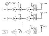
도 1은 MIMO를 지원하는 수신기의 구조를 나타낸다.1 shows a structure of a receiver supporting MIMO.
도 1을 참조하여 알 수 있는 바와 같이, MIMO를 지원하는 수신기는 다수의 안테나와, 다수의 저잡음 증폭기(LNA)와, 다수의 합성기와, 다수의 아날로그 디지털 변환기(ADC)와, 발진기(OSC)와, 위상 고정 로푸(PLL : Phase Locked Loop)를 포함한다.1, a receiver supporting MIMO includes a plurality of antennas, a plurality of low noise amplifiers (LNAs), a plurality of synthesizers, a plurality of analog-to-digital converters (ADCs), an oscillator (OSC) And a phase locked loop (PLL).
상기 안테나로부터 수신된 각 신호들 Tx1, Tx2,.. Txn은 각각의 저잡음 증폭기(LNA)를 통해 증폭된다. 상기 발진기로부터의 신호는 상기 위상 고정 루프에 의해 위상이 고정되어 상기 각 합성기로 배분되고, 상기 각 합성기는 상기 저잡음 증폭기(LNA)로부터의 신호와 합성하여, 각 ADC로 출력한다. 상기 각 ADC는 디지털로 변환하여, 베이스밴드 신호들, 즉 B1, B2, .. Bn으로 출력한다.Each of the signals Tx1, Tx2, ..., Txn received from the antenna is amplified through a respective low noise amplifier (LNA). Signals from the oscillator are fixed in phase by the phase locked loop and distributed to the respective combiners, and the combiners combine with the signal from the low noise amplifier (LNA) and output to the respective ADCs. Each of the ADCs converts the digital signal into digital signals and outputs them as baseband signals, i.e., B1, B2, ..., Bn.
한편, 이와 같이 MIMO 수신기를 포함하는 이동 단말은 최적의 무선 채널을 사용하기 위해서, 채널 측정을 각 수신부 별로 동시에 수행하며, 각 수신부 별로 측정된 값의 대표값을 기지국으로 전송한다.In order to use the optimal radio channel, the mobile station including the MIMO receiver simultaneously performs channel measurement for each receiver and transmits representative values of the measured values to the receiver.
한편, 상기 채널 측정에서 최적의 통신 환경 설정과 무선 자원의 효율적인 활용을 위하여 RSSI(Received Signal Strength Indicator) 등의 다양한 항목이 측정될 수 있다.Various items such as Received Signal Strength Indicator (RSSI) can be measured for optimal communication environment setting and efficient utilization of radio resources in the channel measurement.
상기 MIMO 단말의 경우 이러한 측정 항목들에 대해서 각각의 수신부에서 독립적으로 측정하며, 이에 대한 대표값을 산출하여 상위 계층으로 보고한다. 이에 대한 수식은 다음과 같다.In the case of the MIMO terminal, each of the measurement items is independently measured by each receiver, and a representative value thereof is calculated and reported as an upper layer. The formula for this is as follows.

위 식에서 m1, m2, mn 은 다수의 수신부들 중 각각 1, 2, n 번째의 수신부에서 측정된 순시 측정값이며, f()는 각 측정 항목에 따라 최대값 또는 평균값 등의 통계함수를 의미하며, m은 f() 를 통하여 산출된 해당 측정 항목의 대표값이다. 상위의 계층은 이러한 대표값에 추가적으로 상위 필터링을 거쳐서 오류 확률을 감소시킨 후, 핸드오버나 자원 할당 등 무선 자원 이용에 대한 최적화를 수행하는데 사용하게 된다.In the above equation, m1 , m2 , and mn are instantaneous measurement values measured at the first, second, and n-th receiving units of the plurality of receiving units, and f () is a statistical function , And m is a representative value of the corresponding measurement item calculated through f (). The higher layers are used to perform optimization of radio resources such as handover and resource allocation after lowering the error probability through an upper filter in addition to the representative value.
이러한 무선 전송 기술에서 사용하는 측정 항목은 크게 인트라-프리퀀시(Intra-frequency) 측정과 인터-프리퀀스(Inter-frequency) 측정으로 나뉘어 진다.The measurement items used in this wireless transmission technique are largely divided into an intra-frequency measurement and an inter-frequency measurement.
인트라-프리퀀시 측정은 현재 사용중인 주파수에 대한 측정이다. 이미 베이스밴드(Baseband)와 RF(Radio Frequency)를 포함한 수신부가 현재 사용중인 주파수로 설정되어 있으므로, 서비스를 이용하면서 영향 없이 동시에 수행 가능하다.The intra-frequency measurement is a measure of the frequency currently in use. Since the receiving unit including the baseband and the RF (Radio Frequency) is already set to the currently used frequency, it can be performed simultaneously without any influence while using the service.
반면 인터 프리퀀시 측정은 현재 사용중인 주파수와 다른 주파수에 대한 측정으로, 구현상의 제약 사항으로 인하여 추가적인 별도의 수신부가 없이는, 측정 구간 동안 통화를 포함하여 이용중인 서비스 단절이 필연적이다.On the other hand, the inter-frequency measurement is a measurement for a different frequency than the frequency currently in use. Due to implementation constraints, service disconnection in use, including calls during the measurement interval, is inevitable without an additional separate receiver.
이에 따라 UMTS WCDMA 에서의 압축 모드(Compressed Mode)와 같이 측정 간격(Measurement gap)을 사용하는 형태로 논의되어, 이에 대한 고려가 규격에 포함되어 있지만, 여전히 서비스 중단 또는 통화 품질 저하의 문제가 존재한다.Accordingly, a measurement gap is used as a compressed mode in the UMTS WCDMA. Consideration is included in the standard, but there is still a problem of service interruption or poor call quality .
한편, 이와 같은 인터-프리퀀시 측정의 문제를 해결하기 위해, 최근 표준 LTE-A에서도 활발히 논의되고 있다.On the other hand, in order to solve the problem of the inter-frequency measurement, the standard LTE-A has been actively discussed.
상기 LTE-A의 경우 고속 무선 전송의 실현을 위하여 업링크(Uplink) MIMO와 CA(Carrier Aggregation)을 포함한 다양한 기법이 추가되어 있다. 상기 CA는 다시 Intra-Band Contiguous CA, Intra-Band Non-Contiguous CA 와 Inter-Band Non-Contiguous CA 로 나뉘어 지며, 각각 CA 기능 별로 구현 가능한 UE Architecture 가 제한된다. 기본적으로 CA 를 지원하는 UE Architecture 는 동시에 지원 가능한 CA 의 CC(Component Carrier) 의 개수 별로 송수신부가 요구된다. 하지만 UE 구현상의 여러 이점들을 고려하여 Intra-Band Contiguous CA 의 경우 CA 대역 전체를 동시에 지원 가능한 광 대역의 송수신부를 적용한 Single-RF 구조의 적용이 현재 활발히 논의되고 있다.In the case of the LTE-A, various techniques including uplink MIMO and CA (Carrier Aggregation) are added to achieve high-speed wireless transmission. The CA is divided into an Intra-Band Contiguous CA, an Intra-Band Non-Contiguous CA and an Inter-Band Non-Contiguous CA, respectively. Basically, the UE Architecture supporting the CA requires transmission / reception by the number of CCs (Component Carriers) of the simultaneously supported CAs. However, in consideration of various advantages of the UE implementation, application of a single-RF structure applying a wide band transceiver capable of simultaneously supporting the entire CA band in an Intra-Band Contiguous CA is actively being discussed.
또한 CA 의 경우 P-Cell(Primary Cell)를 제외한 나머지 S-Cell(Secondary Cell)는 단말의 전력 소모 감소를 위하여 채널 및 사용자 데이터 요구량에 따라 수시로 활성/비활성이 가능한 구조로 표준화가 진행되고 있다. 이에 따라 비활성화된 S-Cell 대한 빈번한 측정이 요구된다. 비활성화된 S-Cell 대한 측정은 일종의 인터 프리퀀시(Inter-Frequency) 측정으로 간주할 수 있다. 이러한 반송파 집적에 있어서 기본적으로 병렬로 하드웨어를 사용하는 인트라 밴드 비연속 반송파 집적(Intra-Band Non-Contiguous CA)과 인터 밴드 반송파 집적(Inter-Band CA)의 경우, 비활성화된 S-Cell에 대한 측정은 별도의 서비스 중단 없이 비활성화된 RF 체인을 활성화 함으로써 수행 가능하다.In the case of CA, the remaining S-Cell (Secondary Cell) except for P-Cell (Primary Cell) is being standardized as a structure that can be activated / deactivated occasionally according to the channel and user data requirement in order to reduce power consumption of the terminal. This requires frequent measurements on inactivated S-Cells. The measurement for the deactivated S-Cell can be regarded as a sort of inter-frequency measurement. In the case of Intra-Band Non-Contiguous CA and Inter-Band CA that basically use hardware in parallel for carrier integration, measurement of inactivated S-Cell Can be performed by activating an inactivated RF chain without additional service interruption.
반면, 주로 단일 RF 체인을 사용할 것으로 기대되는 내부 대역 연속 반송파 집적(Intra-Band Contiguous CA) 기술의 경우 비활성화된 S-Cell에 대한 인터 프리퀀스 측정은 베이스 밴드 및 RF의 재설정(Re-tuning)을 포함한 각 수신부의 재설정이 필요하므로 이 구간 동안 서비스 중단이 발생하게 된다.On the other hand, in the case of the intra-band contiguous CA, which is expected to use mainly a single RF chain, the inter-frequency measurement for the deactivated S-Cell is performed by re-tuning the baseband and RF Since the receiver needs to be reset, the service interruption occurs during this interval.
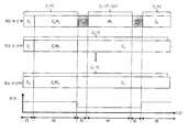
도 2는 MIMO를 지원하고 한번에 하나의 주파수만 수신 가능한 단말에서 각 수신부 별로 측정을 수행함에 따른 상태를 나타낸다.2 shows a state in which measurement is performed for each receiver in a terminal supporting MIMO and capable of receiving only one frequency at a time.
도 2를 참조하여 알 수 있는 바와 같이, 단말은 제1 주파수 f1을 이용하여 서비스를 사용할 수 있으며, 상기 단말은 제2 주파수 f2에 대한 측정을 해야 한다. C1 구간은 현재 서비스가 진행중인 구간이며, T12과 T21은 각각 f1과 f2간에 수신부의 재설정을 하는 구간을 의미한다.As can be seen with reference to FIG. 2, the terminal can use the service using the first frequency f1 , and the terminal has to make a measurement on the second frequency f2 . C1 section is the interval during which the current service is in progress, and T12 and T21 are intervals during which the receiver is reset between f1 and f2 , respectively.
또한 M2 구간은 상기 단말이 제2 주파수 f2에 대한 실제적인 채널 품질 측정을 수행하고 있음을 나타낸다. 각 수신부 별로 주파수 하향 변환기(Frequency Down Converter)에서 사용되는 반송파의 주파수는 각 수신부에 대항하는 구간의 위쪽에 함께 표시되어 있다.And the M2 interval indicates that the UE is performing the actual channel quality measurement for the second frequency f2 . The frequency of the carrier wave used in the frequency down converter for each receiving unit is indicated above the section opposing each receiving unit.
상기 단말은 MIMO를 지원하고 한번에 하나의 주파수만 수신 가능하므로, 상기 T12, M2, T21 구간에서 제1 주파수 f1을 통한 서비스의 중단이 발생하게 된다. 이에 따른 상기 단말의 이상적인 전송률이 상기 도 2의 하단에 나타나 있다.Since the UE supports MIMO and can receive only one frequency at a time, service interruption through the first frequency f1 occurs in the T12 , M2 , and T21 sections. The ideal transmission rate of the terminal is shown in the lower part of FIG.
이와 같은 형태의 측정은 WCDMA의 압축 모드와 같이 통상적인 인터프리퀀시 측정에서 볼 수 있다.This type of measurement can be seen in conventional inter-frequency measurements such as the WCDMA compression mode.
도 3은 MIMO를 지원하고, 한번에 2개 이상의 주파수를 동시에 수신 가능한 단말에서 각 수신부 별로 측정을 수행함에 따른 상태를 나타낸다.FIG. 3 shows a state in which measurement is performed for each receiver in a terminal supporting MIMO and capable of simultaneously receiving two or more frequencies at a time.
도 3을 참조하여 알 수 있는 바와 같이, 단말은 제1 주파수 f1을 이용하여 서비스를 수행할 수 있으며, 제2 주파수 f2에 대해서는 측정을 수행하여야 한다.As can be seen with reference to Figure 3, the terminal can perform the service using the first frequency f1, and the measurement should be performed for the second frequency f2.
이때, C1 구간은 현재 서비스가 진행중인 구간이며, T12와 T21은 각각 제1 주파수 f1과 제2 주파수 f2간에 수신부의 재설정을 하는 구간을 나타낸다. C1M2는 제1 주파수 f1을 이용하여 서비스를 이용할 수 있으나, 제2 주파수 f2에 대해서는 측정을 수행하는 구간이다.In this case, the interval C1 is a period during which the service is currently in progress, and T12 and T21 represent intervals during which the receiver is reset between the first frequency f1 and the second frequency f2 . C1 M2 is a period in which measurement is performed for the second frequency f2 although the service can be used using the first frequency f1 .
각 수신부별로 주파수 하향변환기에서 사용되는 반송파의 주파수는 각 수신부에 해당하는 구간의 위쪽에 함께 표시되어 있다.The frequency of the carrier wave used in the frequency down converter for each receiving unit is indicated above the section corresponding to each receiving unit.
상기 단말은 MIMO를 지원하고 한번에 하나의 주파수만 수신가능하므로, 실질적인 통화 중단은 베이스밴드와 RF를 포함한 수신부의 재설정이 발생하는 T12, T21 구간에서만 발생하게 된다.Since the UE supports MIMO and can receive only one frequency at a time, the actual call interruption occurs only in the T12 and T21 sections in which the receiver including the baseband and the RF is reset.
이에 따른 단말의 이상적이 전송률이 도 3의 하단에 제시되어 있다.The ideal transmission rate of the terminal is shown in the lower part of FIG.
도 3을 참조하여 알 수 있는 바와 같이, 한번에 하나의 주파수만 수신가능한 단말은 도 2에 제시된 것에 비하여 통화 단절구간이 상대적으로 감소되지만, 여전히 통화 단절 구간이 존재한다.As can be seen from FIG. 3, a terminal capable of receiving only one frequency at a time has a relatively shortened call disconnection interval compared to that shown in FIG. 2, but still has a disconnect disconnection interval.
전술한 바와 같이, 인터 프리퀀시 측정을 할 때 별도의 부가적인 하드웨어 도움이 없다면, 서비스 단절이 발생하게 되는 단점이 있다. 또한 측정의 빈도가 증가할수록 상기 서비스 단절은 전체 시스템의 용량 저하, 통화 품질 저화와 같은 문제를 야기하게 된다.As described above, there is a disadvantage in that a service disconnection occurs if there is no additional hardware help in the inter-frequency measurement. Also, as the frequency of the measurement increases, the service disconnection causes problems such as a decrease in the capacity of the entire system and a decrease in call quality.
따라서, 본 발명의 일 실시예는 전술한 문제점을 해결하는 것을 목적으로 한다. 다시 말해서, 본 발명의 일 실시예의 목적은 서비스의 중단을 최소하면서, 수신단이 인터프리퀀시 측정을 수행할 수 있도록하는 것을 목적으로 한다.Therefore, one embodiment of the present invention aims at solving the above-mentioned problems. In other words, an object of an embodiment of the present invention is to enable the receiving end to perform inter-frequency measurement while minimizing the interruption of the service.
또한, 본 발명의 일 실시예는 전체 시스템의 전송률을 증가시킬 수 있고, 서비스 품질을 향상시킬 수 있는 인터프리퀀시 측정방법을 제공하는 것을 목적으로 한다.It is another object of the present invention to provide an inter-frequency measurement method capable of increasing a transmission rate of an entire system and improving a service quality.
전술한 목적을 달성하기 위하여, 본 발명의 일 실시에에 의하면 다수의 수신 안테나를 포함하는 수신기에서 인터 프리퀀시에 대한 측정을 하는 방법이 제공된다.According to an aspect of the present invention, there is provided a method for measuring inter-frequency in a receiver including a plurality of reception antennas.
상기 측정 방법은 제1 안테나 및 제2 안테나 중 하나 이상을 통해 제1 주파수를 이용해 서비스를 수행하는 단계와; 상기 제2 안테나를 통한 제1 주파수를 이용한 서비스의 수행을 지속하면서, 상기 제1 안테나를 이용해 제2 주파수에 대한 측정을 수행하는 단계와; 상기 제1 안테나를 통한 제2 주파수에 대한 측정 결과를 이용하여, 상기 제2 안테나를 통한 상기 제2 주파수에 대한 실제적인 측정없이, 그 측정 결과를 추정하는 단계를 포함할 수 있다.The method includes performing a service using a first frequency through at least one of a first antenna and a second antenna; Performing a measurement on a second frequency using the first antenna while continuing to perform a service using the first frequency through the second antenna; And estimating the measurement result using the measurement result for the second frequency through the first antenna, without actual measurement for the second frequency through the second antenna.
상기 제2 주파수에 대한 측정을 수행하는 동시에, 상기 제1 안테나를 통해서 상기 제1 주파수를 수신 처리하여, 서비스를 수행할 수 있다.And performs a measurement on the second frequency, and receives and processes the first frequency through the first antenna to perform a service.
상기 제2 주파수에 대한 측정을 수행하는 단계는: 상기 제1 안테나의 수신단을 상기 제2 주파수에 맞게 재설정하는 단계를 포함할 수 있다. 상기 재설정하는 동안 상기 제2 안테나를 통해 상기 제1 주파수를 수신 처리하여, 서비스를 수행할 수 있다.The performing the measurement for the second frequency may comprise: resetting the receiving end of the first antenna to the second frequency. And may receive and process the first frequency through the second antenna during the reset.
상기 제2 안테나를 통한 상기 제2 주파수에 대해 측정값은 상기 제1 안테나를 통한 제2 주파수에 대한 측정 결과와, 상기 제1 안테나와 상기 제2 안테나 간의 통계적인 특성 오차값을 이용하여 추정될 수 있다.The measured value for the second frequency through the second antenna is estimated using the measurement result for the second frequency through the first antenna and the statistical characteristic error value between the first antenna and the second antenna .
상기 제2 안테나를 통한 상기 제2 주파수에 대해 측정값이 m2,k라 하면, 상기 m2,k는 수학식
상기 Δ2,kn

한편, 전술한 목적을 달성하기 위하여, 본 발명의 일 실시예에 따르면 다수의 수신 안테나를 포함하는 수신기에서 인터 프리퀀시에 대한 측정을 하는 방법이 제시된다. 상기 측정 방법은 제1 안테나 및 제2 안테나 중 하나 이상을 통해 제1 주파수를 이용해 서비스를 수행하는 단계와; 상기 제1 안테나를 통해 상기 제1 주파수를 이용한 서비스를 지속하면서, 동시에 제1 주파수 및 제2 주파수에 대한 측정을 수행하는 단계와; 상기 제2 안테나를 통한 제1 주파수를 이용한 서비스의 수행을 지속하면서, 상기 제1 주파수에 대한 측정을 수행하는 단계와; 상기 제1 주파수에 대한 제1 안테나와 제2 안테나 간의 측정 결과값의 차이 및 상기 제2 주파수에 대한 상기 제2 안테나에서의 측정 값을 이용하여, 상기 제2 안테나를 통한 상기 제2 주파수에 대한 실제적인 측정없이, 그 측정 결과를 추정하는 단계를 포함할 수 있다.According to another aspect of the present invention, there is provided a method for measuring inter-frequency in a receiver including a plurality of reception antennas. The method includes performing a service using a first frequency through at least one of a first antenna and a second antenna; Performing a measurement for a first frequency and a second frequency simultaneously while continuing service using the first frequency through the first antenna; Performing a measurement on the first frequency while continuing to perform a service using the first frequency through the second antenna; Using a difference between measurement results of the first antenna and the second antenna for the first frequency and a measurement value of the second antenna for the second frequency, And estimating the measurement result without actual measurement.
상기 측정 방법은 상기 제1 안테나를 통해 상기 제1 주파수 및 제2 주파수에 대한 측정을 수행하는 동시에, 상기 제2 안테나를 통해서 상기 제1 주파수를 이용하여 서비스를 수행하는 단계를 더 포함할 수 있다.The measuring method may further include performing a measurement on the first frequency and the second frequency through the first antenna and performing a service using the first frequency through the second antenna .
상기 측정 방법은 상기 제1 안테나를 통해 제1 주파수 및 제2 주파수에 대한 측정을 수행하기 위해, 상기 제1 안테나의 수신단을 상기 제2 주파수에 맞게 재설정하는 단계를 더 포함할 수 있다.The measuring method may further include resetting a receiving end of the first antenna to the second frequency to perform the measurement on the first frequency and the second frequency through the first antenna.
상기 재설정하는 동안 상기 제2 안테나를 통해 상기 제1 주파수를 수신 처리하여, 서비스를 수행할 수 있다.And may receive and process the first frequency through the second antenna during the reset.
본 발명의 일실시예는 측정만을 위한 추가적인 수신부가 없더라도, 현재 이용중인 서비스의 단절을 방지할 수 있도록 한다. 또한, 본 발명의 일 실시예는 전체 시스템의 전송률을 증가시키고, 서비스 품질을 향상시킬 수 있다.An embodiment of the present invention makes it possible to prevent disconnection of a service currently being used even if there is no additional receiver for measurement only. In addition, an embodiment of the present invention can increase the transmission rate of the entire system and improve the service quality.
또한 종래 기술에 대비하여, 본 발명의 일 실시예는 서비스 단절을 대비한 측정 간격(Measurement Gap)의 사용이 불필요함으로 인하여, 시스템 측면에서 스케줄링이 용이해지고, 측정 간격에 의한 간섭의 영향도 감소한다.Also, in contrast to the prior art, one embodiment of the present invention makes it unnecessary to use a measurement gap in preparation for a service disconnection, thereby facilitating scheduling on the system side and reducing the influence of interference due to the measurement interval .
부가적으로 수신부의 잴성정을 최대한 감소함으로인하여, 전력 절감의 효과도 얻을 수 있다.In addition, the effect of power saving can be obtained by minimizing the controllability of the receiving unit.
도 1은 MIMO를 지원하는 수신기의 구조를 나타낸다.
도 2는 MIMO를 지원하고 한번에 하나의 주파수만 수신 가능한 단말에서 각 수신부 별로 측정을 수행함에 따른 상태를 나타낸다.
도 3은 MIMO를 지원하고, 한번에 2개 이상의 주파수를 동시에 수신 가능한 단말에서 각 수신부 별로 측정을 수행함에 따른 상태를 나타낸다.
도 4는 MIMO를 지원하고 한번에 하나의 주파수만 수신 가능한 단말에서 제1 실시예에 따라 각 수신부가 Inter-Frequency Measurement 을 시차를 두고 수행하는 방법을 나타낸 예시도이다.
도 5는 MIMO를 지원하고 한번에 2개 이상의 주파수를 동시에 수신 가능한 단말에서 제1 실시예에 따라 각 수신부가 Inter-Frequency Measurement 을 시차를 두고 수행하는 방법을 나타낸 예시도이다.
도 6은 도 4 및 도 5에 도시된 본 발명의 제1 실시예에 따른 방법을 구현하기 위한 MIMO 수신기의 구조를 나타낸다.
도 7는 MIMO를 지원하고 한번에 하나의 주파수만 수신 가능한 단말에서 제2 실시예에 따라 각 수신부가 Inter-Frequency Measurement을 동시에 수행하는 방법을 나타낸 예시도이다.
도 8는 MIMO를 지원하고 한번에 2개 이상의 주파수를 수신 가능한 단말에서 제2 실시예에 따라 각 수신부가 Inter-Frequency Measurement을 동시에 수행하는 예를 나타낸 예시도이다.
도 9는 도 7 및 도 8에 도시된 본 발명의 제2 실시예에 따른 MIMO 수신기의 구조를 나타낸다.1 shows a structure of a receiver supporting MIMO.
2 shows a state in which measurement is performed for each receiver in a terminal supporting MIMO and capable of receiving only one frequency at a time.
FIG. 3 shows a state in which measurement is performed for each receiver in a terminal supporting MIMO and capable of simultaneously receiving two or more frequencies at a time.
4 is a diagram illustrating a method in which each receiver performs inter-frequency measurement with a parallax according to the first embodiment in a terminal that supports MIMO and can receive only one frequency at a time.
5 is a diagram illustrating a method in which each receiver performs inter-frequency measurement with a time lag according to the first embodiment in a terminal that supports MIMO and can simultaneously receive two or more frequencies at a time.
FIG. 6 shows a structure of a MIMO receiver for implementing the method according to the first embodiment of the present invention shown in FIGS. 4 and 5.
7 is an exemplary diagram illustrating a method in which each receiver simultaneously performs Inter-Frequency Measurement according to the second embodiment in a terminal that supports MIMO and can receive only one frequency at a time.
FIG. 8 is an exemplary diagram illustrating an example in which each receiver simultaneously performs Inter-Frequency Measurement according to the second embodiment in a terminal supporting MIMO and capable of receiving two or more frequencies at a time.
FIG. 9 shows a structure of a MIMO receiver according to a second embodiment of the present invention shown in FIGS. 7 and 8. FIG.
본 명세서에서 사용되는 기술적 용어는 단지 특정한 실시 예를 설명하기 위해 사용된 것으로, 본 발명을 한정하려는 의도가 아님을 유의해야 한다. 또한, 본 명세서에서 사용되는 기술적 용어는 본 명세서에서 특별히 다른 의미로 정의되지 않는 한, 본 발명이 속하는 기술 분야에서 통상의 지식을 가진 자에 의해 일반적으로 이해되는 의미로 해석되어야 하며, 과도하게 포괄적인 의미로 해석되거나, 과도하게 축소된 의미로 해석되지 않아야 한다. 또한, 본 명세서에서 사용되는 기술적인 용어가 본 발명의 사상을 정확하게 표현하지 못하는 잘못된 기술적 용어일 때에는, 당업자가 올바르게 이해할 수 있는 기술적 용어로 대체되어 이해되어야 할 것이다. 또한, 본 발명에서 사용되는 일반적인 용어는 사전에 정의되어 있는 바에 따라, 또는 전후 문맥상에 따라 해석되어야 하며, 과도하게 축소된 의미로 해석되지 않아야 한다.It is noted that the technical terms used herein are used only to describe specific embodiments and are not intended to limit the invention. It is also to be understood that the technical terms used herein are to be interpreted in a sense generally understood by a person skilled in the art to which the present invention belongs, Should not be construed to mean, or be interpreted in an excessively reduced sense. Further, when a technical term used herein is an erroneous technical term that does not accurately express the spirit of the present invention, it should be understood that technical terms that can be understood by a person skilled in the art are replaced. In addition, the general terms used in the present invention should be interpreted according to a predefined or prior context, and should not be construed as being excessively reduced.
또한, 본 명세서에서 사용되는 단수의 표현은 문맥상 명백하게 다르게 뜻하지 않는 한, 복수의 표현을 포함한다. 본 출원에서, "구성된다" 또는 "포함한다" 등의 용어는 명세서 상에 기재된 여러 구성 요소들, 또는 여러 단계들을 반드시 모두 포함하는 것으로 해석되지 않아야 하며, 그 중 일부 구성 요소들 또는 일부 단계들은 포함되지 않을 수도 있고, 또는 추가적인 구성 요소 또는 단계들을 더 포함할 수 있는 것으로 해석되어야 한다.Also, the singular forms "as used herein include plural referents unless the context clearly dictates otherwise. In the present application, the term "comprising" or "comprising" or the like should not be construed as necessarily including the various elements or steps described in the specification, Or may be further comprised of additional components or steps.
또한, 또한, 본 명세서에서 사용되는 구성요소에 대한 접미사 "모듈" 및 "부"는 명세서 작성의 용이함만이 고려되어 부여되거나 혼용되는 것으로서, 그 자체로 서로 구별되는 의미 또는 역할을 갖는 것은 아니다.Furthermore, suffixes "module" and " part "for components used in the present specification are given or mixed in consideration of ease of specification, and do not have their own meaning or role.
또한, 본 명세서에서 사용되는 제1, 제2 등과 같이 서수를 포함하는 용어는 다양한 구성 요소들을 설명하는데 사용될 수 있지만, 상기 구성 요소들은 상기 용어들에 의해 한정되어서는 안 된다. 상기 용어들은 하나의 구성요소를 다른 구성요소로부터 구별하는 목적으로만 사용된다. 예를 들어, 본 발명의 권리 범위를 벗어나지 않으면서 제1 구성요소는 제2 구성 요소로 명명될 수 있고, 유사하게 제2 구성 요소도 제1 구성 요소로 명명될 수 있다.Furthermore, terms including ordinals such as first, second, etc. used in this specification can be used to describe various elements, but the elements should not be limited by the terms. The terms are used only for the purpose of distinguishing one component from another. For example, without departing from the scope of the present invention, the first component may be referred to as a second component, and similarly, the second component may also be referred to as a first component.
이하, 첨부된 도면을 참조하여 본 발명에 따른 바람직한 실시예를 상세히 설명하되, 도면 부호에 관계없이 동일하거나 유사한 구성 요소는 동일한 참조 번호를 부여하고 이에 대한 중복되는 설명은 생략하기로 한다.Hereinafter, exemplary embodiments of the present invention will be described in detail with reference to the accompanying drawings, wherein like reference numerals refer to like or similar elements throughout the several views, and redundant description thereof will be omitted.
또한, 본 발명을 설명함에 있어서 관련된 공지 기술에 대한 구체적인 설명이 본 발명의 요지를 흐릴 수 있다고 판단되는 경우 그 상세한 설명을 생략한다. 또한, 첨부된 도면은 본 발명의 사상을 쉽게 이해할 수 있도록 하기 위한 것일 뿐, 첨부된 도면에 의해 본 발명의 사상이 제한되는 것으로 해석되어서는 아니 됨을 유의해야 한다.In the following description, well-known functions or constructions are not described in detail since they would obscure the invention in unnecessary detail. It is to be noted that the accompanying drawings are only for the purpose of facilitating understanding of the present invention, and should not be construed as limiting the scope of the present invention with reference to the accompanying drawings.
이하, 본 발명의 실시예들에 대해서 구체적으로 설명하기에 앞서, 이해를 도모하고자 간략하게 설명하기로 한다.BRIEF DESCRIPTION OF THE DRAWINGS FIG. 1 is a block diagram showing a configuration of a first embodiment of the present invention;
본 발명에 따르면 서비스의 단절없이 측정하는 하기 위한 제1 실시예 및 제2 실시예를 제시한다. 제1 실시예에 따르면 각 수신부가 시차를 두고 측정을 수행하여 서비스 단절을 제거한다. 제2 실시예에 따르면 하나의 수신부만 실질적인 측정을 하고, 상기 측정을 통해 얻어진 결과와, 각 수신부별 특성 차이를 이용하여 나머지 수신부의 측정 결과를 추정한다. 이하에 이러한 제1 실시예 및 제2 실시예에 대해서 상세하게 설명하기로 한다.According to the present invention, first and second embodiments for measuring without service disruption are presented. According to the first embodiment, each receiving unit performs measurement with a time difference to eliminate a service disconnection. According to the second embodiment, only one receiving unit performs a substantial measurement, and the measurement result of the remaining receiving unit is estimated by using the difference between the results obtained by the measurement and the characteristics of the respective receiving units. Hereinafter, the first embodiment and the second embodiment will be described in detail.
도 4는 MIMO를 지원하고 한번에 하나의 주파수만 수신 가능한 단말에서 제1 실시예에 따라 각 수신부가 Inter-Frequency Measurement 을 시차를 두고 수행하는 방법을 나타낸 예시도이다.4 is a diagram illustrating a method in which each receiver performs inter-frequency measurement with a parallax according to the first embodiment in a terminal that supports MIMO and can receive only one frequency at a time.
도 4를 참조하여 알 수 있는 바와 같이, 단말은 제1 주파수 f1을 이용하여 서비스를 사용할 수 있으며, 상기 단말은 제2 주파수 f2에 대한 측정을 해야 한다. C1 구간은 현재 서비스가 진행중인 구간이며, T12과 T21은 각각 제2 주파수 f1과 제2 주파수 f2간에 수신부의 재설정을 하는 구간을 의미한다.As can be seen with reference to FIG. 4, the terminal can use the service using the first frequency f1 , and the terminal has to make a measurement on the second frequency f2 . C1 is a period during which the service is currently in progress, and T12 and T21 are periods during which the receiver is reset between the second frequency f1 and the second frequency f2 .
또한 M2 구간은 상기 단말이 제2 주파수 f2에 대한 실제적인 채널 품질 측정을 수행하고 있음을 나타낸다. 각 수신부 별로 주파수 하향 변환기(Frequency Down Converter)에서 사용되는 반송파의 주파수는 각 수신부에 대항하는 구간의 위쪽에 함께 표시되어 있다.And the M2 interval indicates that the UE is performing the actual channel quality measurement for the second frequency f2 . The frequency of the carrier wave used in the frequency down converter for each receiving unit is indicated above the section opposing each receiving unit.
한번에 하나의 주파수만 수신 가능한 단말에서, 종래 기술에 따라 측정을 수행하면 T12, M2, T21 구간에서 서비스 중단이 발생하게 된다. 그러나, 본 발명에서는 한번의 하나의 수신부만 서비스 중단 기간에 들어갈 수 있도록 시차를 두고 배치함으로써 전체 측정 기간은 다소 증가하지만, 서비스 중단 기간은 발생하지 않는다. 또한, 측정 구간에서 전체 전송률은 다소 저하 되겠지만, 한번에 하나의 수신부만 중단이 발생하지 않으므로, 전송률의 저하는 무시될 만하다. 또한, 한편, 별도의 측정 갭이 필요하지 않게 되는 장점이 있다.In a terminal capable of receiving only one frequency at a time, if measurement is performed according to the related art, a service interruption occurs in the T12 , M2 , and T21 sections. However, in the present invention, the entire measurement period is somewhat increased by arranging the time difference so that only one reception unit can enter the service interruption period, but the service interruption period does not occur. In addition, although the overall transmission rate may be somewhat reduced in the measurement period, the decrease in the transmission rate is negligible since only one reception unit at a time does not cause an interruption. On the other hand, there is an advantage that a separate measurement gap is not required.
이에 따른 단말의 이상적이 전송률이 도 4의 하단에 제시되어 있다.The ideal transmission rate of the terminal is shown in the lower part of FIG.
도 5는 MIMO를 지원하고 한번에 2개 이상의 주파수를 동시에 수신 가능한 단말에서 제1 실시예에 따라 각 수신부가 Inter-Frequency Measurement 을 시차를 두고 수행하는 방법을 나타낸 예시도이다.5 is a diagram illustrating a method in which each receiver performs inter-frequency measurement with a time lag according to the first embodiment in a terminal that supports MIMO and can simultaneously receive two or more frequencies at a time.
도 5를 참조하여 알 수 있는 바와 같이, 단말은 제1 주파수 f1을 이용하여 서비스를 사용할 수 있으며, 상기 단말은 제2 주파수 f2에 대한 측정을 해야 한다. C1 구간은 현재 서비스가 진행중인 구간이며, T12과 T21은 각각 제1 주파수 f1과 제2 주파수 f2간에 수신부의 재설정을 하는 구간을 의미한다. C1M2는 제1 주파수 f1에서는 서비스를 이용 중에 있고, 제2 주파수 f2에 대해서는 측정을 수행하는 구간이다.As can be seen with reference to FIG. 5, the terminal can use the service using the first frequency f1 , and the terminal has to make a measurement on the second frequency f2 . C1 section is a period during which the current service is in progress, and T12 and T21 are intervals during which the receiver is reset between the first frequency f1 and the second frequency f2 . C1 M2 is a service using the service at the first frequency f1 and performing the measurement for the second frequency f2 .
각 수신부 별로 주파수 하향 변환기(Frequency Down Converter)에서 사용되는 반송파의 주파수는 각 수신부에 대항하는 구간의 위쪽에 함께 표시되어 있다.The frequency of the carrier wave used in the frequency down converter for each receiving unit is indicated above the section opposing each receiving unit.
도 5에서는 단말이 동시에 2개의 주파수를 수신 가능한 수신부를 포함하는 것으로 가정하였으므로, 실질적인 통화 중단은 베이스밴드와 RF의 재설정이 발생하는 T12, T21 구간에서만 각 수신부별로 서비스 중단이 발생하게 된다. 그러나, 상기 제1 실시예에 따르면 상기 각 수신부는 상기 측정을 시차를 두어 수행하므로, 상기 서비스 중단이 발생하는 T12, T21 구간이 상기 수신부마다 서로 달라, 각 수신부에 의한 T12 구간이 서로 중첩되지 않으며, 또한 상기 T21 구간이 서로 중첩되지 않는다. 이에 따라 전체 측정 기간은 약간 증가하지만, 이러한 증가량은 통상적으로 베이스밴드와 RF의 재설정에 필요한 시간 T12, T21보다 측정에 필요한 시간 C1M2가 상대적으로 크므로, 크게 영향이 없다.In FIG. 5, it is assumed that the UE includes a receiver capable of receiving two frequencies at the same time. Thus, the actual call interruption occurs only in the T12 and T21 periods where baseband and RF reset occur. However, according to the first embodiment, since each of the receiving units performs the measurement with a time lag, the T12 and T21 sections where the service interruption occurs differ from each other to the receiving units, and the T12 sections And the T21 sections do not overlap with each other. Therefore, the total measurement time is slightly increased, but this increase amount is not largely affected because the time C1 M2 required for measurement is relatively larger than the time T12 , T21 required for resetting the base band and the RF.
도 5에 도시된 방법에 따른 이상적인 UE 의 전송률이 도 5의 하단에 제시되어 있다. 즉, 도 5에 도시된 바와 같이, 도 3에 제시된 방법에 비하여 통화 단절 구간이 없음을 볼 수 있다.The ideal UE transmission rate according to the method shown in FIG. 5 is shown at the bottom of FIG. That is, as shown in FIG. 5, it can be seen that there is no call disconnection section in comparison with the method shown in FIG.
도 6은 도 4 및 도 5에 도시된 본 발명의 제1 실시예에 따른 방법을 구현하기 위한 MIMO 수신기의 구조를 나타낸다.FIG. 6 shows a structure of a MIMO receiver for implementing the method according to the first embodiment of the present invention shown in FIGS. 4 and 5.
본 발명의 제1 실시예에 따른 방법은 각 수신부가 측정을 동시에 수행하지 않고, 시차를 두고 수행할 수 있도록 한다. 따라서, 각 수신부의 주파수 하향 변환기에 입력되는 반송파가 각 수신부 별로 독립적으로 최대 2개의 부반송파가 요구되므로, 2개의 위상 고정 루프(Phase Locked Loop: PLL)과 각 수신부별로 적절한 위상 고정 로프를 선택하기 위한 스위치가 요구된다.The method according to the first embodiment of the present invention allows each receiving unit to perform the measurement at a time difference rather than simultaneously. Therefore, since a maximum of two subcarriers are required for a carrier input to the frequency down converter of each receiving unit independently for each receiving unit, there are two phase locked loops (PLLs) and a phase locked loop A switch is required.
구체적으로, 도 6을 참조하여 알 수 있는 바와 같이, 본 발명의 제1 실시예에 따른 MIMO 수신기(100)는 발진부(150)와, n개의 수신부(도 6에서는 수신부(110, 120, …140))을 포함할 수 있다.6, the
상기 발진부(150)는 발진부(OSC)(155)와, 제1 및 제2 위상 고정 루프(Phase Locking Loop: PLL)(151, 152)를 포함한다.The
상기 제1 수신부(110)는 제1 안테나(111), 제1 저잡음증폭기(Low Noise Amplifier: LNA)(112)와, 제1 합성기(113)와 제1 스위치(114)와, 제1 아날로그-디지털변환기(ADC)(115)를 포함할 수 있다. 상기 제2 수신부(120)는 제2 안테나(121), 제2 저잡음증폭기(Low Noise Amplifier: LNA)(122)와, 제2 합성기(123)와 제2 스위치(124)와, 제1 아날로그-디지털변환기(ADC)(125)를 포함할 수 있다. 한편, n번째 수신부, 예컨대 제4 수신부(140)도 마찬가지로 제4 안테나(141), 제4 저잡음증폭기(Low Noise Amplifier: LNA)(142)와, 제4 합성기(143)와 제4 스위치(144)와, 제4 아날로그-디지털변환기(ADC)(145)를 포함할 수 있다.The
이하 동작을 설명하면 다음과 같다.Hereinafter, the operation will be described.
상기 제1 위상 고정 루프(151)는 상기 발진부(155)로부터의 생성된 신호를 제1 주파수 f1으로 고정하여 출력할 수 있다. 상기 제2 위상 고정 루프(152)는 상기 발진부(155)로부터의 생성된 신호를 제2 주파수 f2으로 고정하여 출력할 수 있다.The first phase locked
상기 제1 위상 고정 루프(151)의 출력은 각각의 스위치(114, 124, 144)로 배분된다. 또한, 상기 제2 위상 고정 루프(152)의 출력의 출력도 각각의 스위치(114, 124, 144)로 배분된다.The output of the first phase locked
상기 각각의 스위치(114, 124, … 144)는 제어부(미도시)의 제어에 따라 상기 제1 위상 고정 루프(151)의 출력 및 상기 제2 위상 고정 루프(152)의 출력 중 하나 이상을 선택하여, 각각의 합성기(113, 123, … 144)로 입력한다.Each of the
상기 각각의 안테나(111, 121, … 141)에 의해 수신된 신호는 각각의 저잡음 증폭기(112, 122, 142)를 거쳐 증폭되고, 각각의 합성기(113, 123, … 144)로 입력된다.The signals received by the
상기 각각의 합성기(113, 123, … 144)는 제1 위상 고정 루프(151)의 출력 및 상기 제2 위상 고정 루프(152)의 출력 중 상기 각각의 스위치(114, 124, …144)의 의해 선택된 것과 상기 각각의 저잡음 증폭기(112, 122, … 142)에 의해 증폭된 신호를 합성한다. 각각의 아날로그-디지털 변환기(115, 125, … 145)는 상기 합성된 신호를 디지털 변환하여 BB1, BB2, BBn으로 출력한다.Each of the
이와 같은 구성을 통해 도 4에 도시된 방법이 동작하는 과정을 설명하면 다음과 같다.The operation of the method shown in FIG. 4 will now be described with reference to FIG.
먼저, 상기 제1 위상 고정 루프(151)는 상기 발진기(155)의 위상을 제2 주파수 f1에 맞도록 조정하여 출력하고, 상기 제2 위상 고정 루프(152)는 상기 발진기(155)의 위상을 제2 주파수 f2에 맞도록 조정하여 출력한다고 가정하자.The first phase locked
도 4에 도시된 t1 시간에 제1 수신부(110)에서 상기 제1 스위치(114)는 상기 제1 위상 고정 루프(151)의 출력, 즉 제1 주파수 f1을 선택하여 상기 제1 합성기(113)으로 출력한다. 마찬가지로 t1 시간에 제2 내지 제4 수신부(120,… 140)에서 상기 제2 내지 제4 스위치(124,… 144)는 상기 제1 위상 고정 루프(151)의 출력, 즉 제1 주파수 f1을 선택하여 상기 제2 내지 제4 합성기(123, … 143)으로 출력한다. 따라서, 상기 t1 시간에 상기 제1 수신부(110), 제2 수신부(120) 내지 제4 수신부(140)에서는 제1 주파수 f1을 통한 서비스를 가능하게 한다.4, the
한편, t2 시간에 상기 제1 수신부(110)에서 상기 제1 스위치(114)는 상기 제2 위상 고정 루프(152)의 출력, 즉 제2 주파수 f2을 선택하기 위하여 스위칭을 한다. 상기 스위칭하는 t2 시간 동안 상기 제1 수신부(110)는 제1 주파수 f1을 처리할 수 없어, 서비스 단절이 발생한다. 그러나, 상기 t2 시간 동안 제2 내지 제4 수신부(120,.. 140)에서 상기 제2 내지 제4 스위치(124, …144)는 상기 제1 위상 고정 루프(151)의 출력, 즉 제1 주파수 f1을 선택하여 상기 제2 내지 제4 합성기(123, …133)으로 출력하므로, 제1 주파수 f1을 통한 서비스의 단절이 발생하지 않는다. 따라서, 전체적으로 t2 시간동안 서비스의 단절은 발생하지 않는다.On the other hand, the
한편, t3시간에 상기 제1 수신부(110)에서 상기 제1 스위치(114)는 상기 제2 위상 고정 루프(152)의 출력, 즉 제2 주파수 f2을 선택하여 상기 제1 합성기(113)으로 출력한다. 상기 t3 시간 동안 상기 제1 수신부(110)는 제2 주파수 f2를 통한 측정을 수행하므로, 상기 제1 수신부(110)를 통해서는 제1 주파수 f1을 통한 서비스를 처리할 수 없다. 그러나, t3 시간 동안 제2 내지 제4 수신부(120,… 140)에서 상기 제2 내지 제4 스위치(124, … 134)는 상기 제1 위상 고정 루프(151)의 출력, 즉 제1 주파수 f1을 선택하여 상기 제2 내지 제4 합성기(123, …133)으로 출력하므로, 제1 주파수 f1을 통한 서비스의 단절이 발생하지 않는다. 따라서, 전체적으로 t2 시간동안 서비스의 단절은 발생하지 않는다.On the other hand, in the
한편, t4 시간 동안 상기 제1 수신부(110)에서 상기 제1 스위치(114)는 상기 제1 위상 고정 루프(151)의 출력, 즉 제1 주파수 f1을 선택하기 위하여 스위칭을 한다.Meanwhile, the
그리고 t5 시간 동안 상기 제2 스위치(114)는 상기 제2 위상 고정 루프(152)의 출력, 즉 제2 주파수 f2을 선택하기 위하여 스위칭을 한다.And the
그리고 t6 시간 동안 상기 제2 수신부(120)는 제2 주파수 f2를 통한 측정을 수행하므로, 상기 제2 수신부(110)를 통해서는 제1 주파수 f1을 통한 서비스를 처리할 수 없다. 그러나, t6 시간 동안 제1 및 제4 수신부(110, 140)에서 상기 제1 및 제4 스위치(114, 144)는 상기 제1 위상 고정 루프(151)의 출력, 즉 제1 주파수 f1을 선택하여 상기 제1 및 제4 합성기(113, 143)으로 출력하므로, 제1 주파수 f1을 통한 서비스의 단절이 발생하지 않는다. 따라서, 전체적으로 t6 시간 동안 서비스의 단절은 발생하지 않는다.Since the
한편, 전술한 도 6의 구성을 통해 도 5에 도시된 방법이 동작하는 과정을 설명하면 다음과 같다.The operation of the method shown in FIG. 5 through the configuration of FIG. 6 will now be described.
도 6에 도시된 t1 시간에 제1 수신부(110)에서 상기 제1 스위치(114)는 상기 제1 위상 고정 루프(151)의 출력, 즉 제1 주파수 f1을 선택하여 상기 제1 합성기(113)으로 출력한다. 마찬가지로 t1 시간에 제2 및 제4 수신부(120,… 140)에서 상기 제2 내지 제4 스위치(124,… 144)는 상기 제1 위상 고정 루프(151)의 출력, 즉 제1 주파수 f1을 선택하여 상기 제2 내지 제4 합성기(123, …143)으로 출력한다. 따라서, 상기 t1 시간에 상기 제1 수신부(110), 제2 수신부(120), 제4 수신부(140)에서는 제1 주파수 f1을 통한 서비스를 가능하게 한다.6, the
한편, t2 시간에 상기 제1 수신부(110)에서 상기 제1 스위치(114)는 상기 제1 위상 고정 루프(151)의 출력, 즉 제1 주파수 f1 및 상기 제2 위상 고정 루프(152)의 출력, 즉 제2 주파수 f2을 모두 선택하기 위하여 스위칭을 한다. 상기 스위칭하는 t2 시간 동안 상기 제1 수신부(110)는 제1 주파수 f1을 처리할 수 없어, 서비스 단절이 발생한다. 그러나, 상기 t2 시간 동안 제2 내지 제4 수신부(120, …. 140)에서 상기 제2 내지 제4 스위치(124, 144)는 상기 제1 위상 고정 루프(151)의 출력, 즉 제1 주파수 f1을 선택하여 상기 제2 내지 제4 합성기(123, … 143)으로 출력하므로, 제1 주파수 f1을 통한 서비스의 단절이 발생하지 않는다. 따라서, 전체적으로 t2 시간동안 서비스의 단절은 발생하지 않는다.On the other hand, in the
한편, t3 시간 동안 상기 제2 스위치(114)는 상기 제2 위상 고정 루프(152)의 출력, 즉 제2 주파수 f2을 선택하기 위하여 스위칭을 한다. 상기 t3 시간 상기 제1 스위치(114)는 상기 제1 위상 고정 루프(151)의 출력, 즉 제1 주파수 f1과 상기 제2 위상 고정 루프(152)의 출력, 즉 제2 주파수 f2을 모두 선택하여, 상기 제1 합성기(113)으로 출력함으로써, 제1 주파수 f1을 통한 서비스 처리함과 동시에, 제2 주파수 f2를 통해서는 측정을 할 수 있도록 한다. 한편, t3 시간 동안 상기 제4 스위치(144)는 상기 제1 위상 고정 루프(151)의 출력, 즉 제1 주파수 f1을 선택하여 상기 제4 합성기(143)으로 출력한다. 따라서, 전체적으로 t3 시간 동안 서비스의 단절은 발생하지 않는다.On the other hand, the
이상에서 설명한 바와 같이, 제1 실시예에 따른 측정 방법에 따르면 음성 통화와 같은 경우 측정 간격(Measurement Gap)이 필요 없게 되고, 그에 따라 측정 간격(Measurement Gap) 을 처리하기 위하여, 부가적인 신호처리 과정을 생략할 수 있다. 또한, 이와 같이 측정 간격을 사용하지 않으므로, 제어국의 스케줄링 측면에서도 이점을 가진다. 그러나, 제1 실시예에 따른 측정 방법은 실질적인 측정 기간이 증가하므로 전체 전송률 측면에서는 기존 방식에 비하여 큰 이득이 없다. 이하에서는 보다 개선된 제2 실시예에 대해서 설명하기로 한다.As described above, according to the measuring method according to the first embodiment, a measurement gap is not required in the case of a voice call, and in order to process the measurement gap (Measurement Gap) Can be omitted. Moreover, since the measurement interval is not used in this manner, the control station has an advantage in terms of scheduling. However, since the measurement method according to the first embodiment increases the actual measurement period, there is no large gain in terms of the overall transfer rate as compared with the conventional method. Hereinafter, a second improved embodiment will be described.
도 7는 MIMO를 지원하고 한번에 하나의 주파수만 수신 가능한 단말에서 제2 실시예에 따라 각 수신부가 Inter-Frequency Measurement을 동시에 수행하는 방법을 나타낸 예시도이다.7 is an exemplary diagram illustrating a method in which each receiver simultaneously performs Inter-Frequency Measurement according to the second embodiment in a terminal that supports MIMO and can receive only one frequency at a time.
대부분의 측정에서 인터-프리퀀시(Inter-frequency) 측정은 수신 대역 전체에 대한 광대역 측정값만이 사용되며, 수신 대역내의 부채널별로 채널 상태에 대한 측정을 수행하는 경우는 대부분의 경우 인트라-프리퀀시(Intra-frequency) 에 대한 측정에 한한다.In most measurements, inter-frequency measurement uses only the broadband measurement over the entire receive band, and when performing measurements on the channel status for each subchannel in the receive band, the inter- Intra-frequency).
따라서 서비스 중인 제1 주파수 f1 과 측정하고자 하는 제2 주파수 f2 의 광대역 측정값에 대한 통계적인 특성은 거의 유사하며, 특히 제1 주파수 f1과 제2 주파수 f2의 차이가 그리 크지 않은 경우, 이러한 유사성은 증가한다. 따라서 n 번째 수신부에서 제2 주파수 f2에 대한 실질적인 측정을 수행한 경우, k 번째 수신부에서 제2 주파수 f2에 대해 실질적으로 측정을 수행하지 않더라도, 그 측정값 m2,k(k 번째 수신부에서 제2 주파수 f2에 대한 측정값)는 다음 수식과 같이 추정될 수 있다.Therefore, the statistical characteristics of the first frequency f1 being in service and the second frequency f2 to be measured are substantially similar to each other, and particularly when the difference between the first frequency f1 and the second frequency f2 is not so large , This similarity increases. Therefore, in case of performing a practical measurement of the second frequency f2 in the n-th receiving unit, without performing substantially measured on the second frequency f2 in the k-th receiver, the measure m2, k (from the k-th receiver the measured value for the second frequency f2) can be estimated as shown in the following formula:


위 수식에서 Δ2,kn는 제2 주파수 f2에 대한 k 번째 수신부와 n 번째 수신부에 대한 통계적인 특성의 오차이다. 마찬가지로 Δ1,kn 해당 측정 항목에 대한 제1 주파수 f1에 대한 k 번째 수신부와 n 번째 수신부에 대한 통계적인 특성의 오차이다.In the above formula, Δ2,kn is the error of the statistical properties for the k-th and n-th reception unit for receiving the second frequency f2. Similarly, Δ1,kn is the error of the statistical properties for the k-th and n-th reception unit for receiving the first frequency f1 for the corresponding metric.
이하, 이러한 추정을 통한 구체적인 방법을 도 7을 참조하여 설명하면 다음과 같다.Hereinafter, a concrete method through such estimation will be described with reference to FIG.
도 7을 참조하여 알 수 있는 바와 같이, 단말은 제1 주파수 f1을 이용하여 서비스를 사용할 수 있으며, 상기 단말은 제2 주파수 f2에 대한 측정을 해야 한다. C1 구간은 현재 서비스가 진행중인 구간이며, T12과 T21은 각각 제2 주파수 f1과 제2 주파수 f2간에 수신부의 재설정을 하는 구간을 의미한다.As can be seen from FIG. 7, the terminal can use the service using the first frequency f1 , and the terminal has to make a measurement on the second frequency f2 . C1 is a period during which the service is currently in progress, and T12 and T21 are periods during which the receiver is reset between the second frequency f1 and the second frequency f2 .
또한 M2 구간은 상기 단말이 제2 주파수 f2에 대한 실제적인 채널 품질 측정을 수행하고 있음을 나타낸다. C1M2는 제1 주파수 f1에서는 서비스를 이용 중에 있고, 제2 주파수 f2에 대해서는 측정을 수행하는 구간이다. 각 수신부 별로 주파수 하향 변환기(Frequency Down Converter)에서 사용되는 반송파의 주파수는 각 수신부에 대항하는 구간의 위쪽에 함께 표시되어 있다.And the M2 interval indicates that the UE is performing the actual channel quality measurement for the second frequency f2 . C1 M2 is a service using the service at the first frequency f1 and performing the measurement for the second frequency f2 . The frequency of the carrier wave used in the frequency down converter for each receiving unit is indicated above the section opposing each receiving unit.
도 7에서 M2 구간은 하나의 수신부에만 존재하며, 나머지 수신부에서 제2 주파수 f2 에 대한 측정값은 C1M1 구간 동안 각 수신부별로 제1 주파수 f1에 대하여 측정된 값으로부터 추정이 가능하다.In FIG. 7, the M2 section exists only in one receiving section, and the measured values for the second frequency f2 in the remaining receiving sections can be estimated from the values measured for the first frequency f1 for each receiving section during the C1 M1 section Do.
이에 따라 본 발명에서 제안하는 제2 실시예에 따르면 측정 구간의 증가나 통화 중단 없이 측정이 가능하며, 이에 따른 이상적인 단말의 전송률이 도 7의 하단에 제시되어 있다.Accordingly, according to the second embodiment of the present invention, the measurement can be performed without increasing the measurement interval or interrupting the call, and the ideal transmission rate of the terminal is shown at the bottom of FIG.
한편, 본 발명에서 제안하는 제2 실시예에 따르면 수신부의 재설정에 따른 전력 소모도 하나의 수신부에 대해서만 수행되므로, 수신기의 전력소모도 감소하게 된다.Meanwhile, according to the second embodiment of the present invention, power consumption due to resetting of the receiving unit is performed only for only one receiving unit, thereby reducing power consumption of the receiver.
도 8는 MIMO를 지원하고 한번에 2개 이상의 주파수를 수신 가능한 단말에서 제2 실시예에 따라 각 수신부가 Inter-Frequency Measurement을 동시에 수행하는 예를 나타낸 예시도이다.FIG. 8 is an exemplary diagram illustrating an example in which each receiver simultaneously performs Inter-Frequency Measurement according to the second embodiment in a terminal supporting MIMO and capable of receiving two or more frequencies at a time.
도 8을 참조하여 알 수 있는 바와 같이, 단말은 제1 주파수 f1을 이용하여 서비스를 사용할 수 있으며, 상기 단말은 제2 주파수 f2에 대한 측정을 해야 한다. C1 구간은 현재 서비스가 진행중인 구간이며, T12과 T21은 각각 제1 주파수 f1과 제2 주파수 f2간에 수신부의 재설정을 하는 구간을 의미한다.As can be seen from FIG. 8, the terminal can use the service using the first frequency f1 , and the terminal has to make a measurement on the second frequency f2 . C1 section is a period during which the current service is in progress, and T12 and T21 are intervals during which the receiver is reset between the first frequency f1 and the second frequency f2 .
또한 M2 구간은 상기 단말이 제2 주파수 f2에 대한 실제적인 채널 품질 측정을 수행하고 있음을 나타낸다. C1M1는 제1 주파수 f1을 이용하여 데이터 수신과 측정을 수행하는 구간을 의미하고, C1M2는 제1 주파수 f1을 통해서는 서비스를 이용 중에 있고, 제2 주파수 f2에 대해서는 측정을 수행하는 구간이다. 각 수신부 별로 주파수 하향 변환기(Frequency Down Converter)에서 사용되는 반송파의 주파수는 각 수신부에 대항하는 구간의 위쪽에 함께 표시되어 있다.And the M2 interval indicates that the UE is performing the actual channel quality measurement for the second frequency f2 . A C1 M1 has the first use of the first frequency f1, by means a section that performs data reception and measurements, and C1, M2, is used for the service through the first frequency f1, the second frequency f2, Is a section for performing measurement. The frequency of the carrier wave used in the frequency down converter for each receiving unit is indicated above the section opposing each receiving unit.
도 8에서 고려된 단말은 동시에 복수의 주파수를 수신 가능한 수신부로 구성되어 있으므로, 실질적인 통화 중단은 베이스밴드와 RF의 재설정이 발생하는 T12, T21 구간에서만 서비스 중단이 발생하게 된다. 또한 이러한 수신부 재설정 구간마저 하나의 수신부에서만 존재하게 된다.Since the terminal considered in FIG. 8 is composed of a receiver capable of receiving a plurality of frequencies at the same time, the service interruption occurs only in the T12 and T21 sections where baseband and RF reset occur. In addition, such a receiver reset section exists in only one receiving section.
수학식 2을 계산하기 위해 실질적으로 필요한 m2는 하나의 수신부에서만 측정 되고, 나머지는 현재 데이터 수신중인 제1 주파수 f1에 대해서 병렬로 측정된 각 수신부의 측정값 m1으로부터 추정이 가능하므로, 측정 구간의 증가나 통화 중단 없이 측정이 가능하다.M2 practically necessary to calculate the equation (2) is measured in only one of the reception unit, so the rest estimate is available from the current data being received measured values of the respective receiving a measured first in parallel with respect to the first frequency f1, m1, Measurement Period And can be measured without interruption.
이상적인 단말의 전송률이 도 8의 하단에 제시되어 있다. 또한, 수신부의 재설정에 따른 전력 소모도 하나의 수신부에 대해서만 수행되므로, 단말의 전력소모도 감소하게 된다.The ideal rate of the terminal is shown in the lower part of Fig. In addition, power consumption due to the reset of the receiving unit is also performed for only one receiving unit, so that the power consumption of the terminal also decreases.
한편, 서비스중인 제1 주파수 f1에 대한 측정값 m1 으로부터, 측정 대상인 제2 주파수 f2에 대한 측정값 m2를 추정하기 위한 오차 Δ1,kn는 기본적으로 통계적인 특성이 수신부들 간에 거의 정적으로 유지되는 경우 단순한 차이로써 쉽게 구할 수 있으며 다음과 같다.On the other hand, almost static from measurements m1 for the first frequency f1 in service, the error for estimating the measured value m2 of the second frequency f2 to be measured Δ1,kn are basically statistical characteristics between the receiver If it is maintained, it can be easily obtained by simple difference.

다른 한편, 추가적인 측정의 정확도가 요구되는 경우, 제1 실시예에 따른 방법과 조합하여 사용이 가능하다. 예를 들면, 사전에 일정 구간 제1 실시예에 따른 방법으로 통계적인 보정값에 대한 룩업(Look-up) 테이블을 구하고, 이 룩업(Look-up) 테이블에 의하여, 제1 주파수 f1에 대한 측정값 m1으로부터 제2 주파수 f2에 대한 측정값 m2를 추정하기 위한 오차 Δ1,kn를 구할 수 있다.On the other hand, if additional measurement accuracy is required, it can be used in combination with the method according to the first embodiment. For example, certain prior interval of the first embodiment to obtain a look-up (Look-up) tables for the statistical compensation value to the process according to the example, by a look-up (Look-up) table, first for the first frequency f1, It can be determined an error Δ1,kn for estimating the measured value m2 of the second frequency f2 from the measurement value m1.
한편 지금까지 설명한 제2 실시예에 따른 방법을 구현하기 위한 MIMO 수신기는 인터-프리퀀시 f2에 대한 실질적인 측정은 기준이 되는 하나의 수신부만 수행하며, 상기 측정 전/후에 동일 측정 항목에 대하여, 현재 서비스 중인 제1 주파수 f1에 대해서 인트라-프리퀀시 측정을 수행하여 측정된 값을 기준으로 인트라-프리퀀시 측정에서 필요한 수신부별 특성 차이를 보상하는 구조로 이루어진다.On the other hand, in the MIMO receiver for implementing the method according to the second embodiment described above, the actual measurement of the inter-frequency f2 is performed only by one receiver as a reference, and for the same measurement items before and after the measurement, on the basis of the measured value by performing a measurement frequency intra-intra for the service that is the first frequency f1 it comprises a structure for compensating for the characteristics by receiving a difference necessary in the frequency measurement.
지금까지 설명한 제2 실시예에 따른 방법은 도 6에 제시된 수신기 구조를 통하여서도 동작이 가능하지만, 보다 간단화된 수신기에서도 동작될 수 있다.The method according to the second embodiment described so far is operable through the receiver structure shown in Fig. 6, but can also be operated with a simpler receiver.
이하, 보다 간단화된 수신기의 구조를 도 9를 참조하여 설명하기로 한다.Hereinafter, a more simplified structure of the receiver will be described with reference to FIG.
도 9는 도 7 및 도 8에 도시된 본 발명의 제2 실시예에 따른 MIMO 수신기의 구조를 나타낸다.FIG. 9 shows a structure of a MIMO receiver according to a second embodiment of the present invention shown in FIGS. 7 and 8. FIG.
본 발명의 제2 실시예에 따른 방법은 기본적으로 2개의 반송파를 동시에 사용하므로, 2개의 위상 고정 루프(Phase Locked Loop: PLL) 가 요구된다.Since the method according to the second embodiment of the present invention basically uses two carriers simultaneously, two phase locked loops (PLLs) are required.
구체적으로, 도 9를 참조하여 알 수 있는 바와 같이, 본 발명의 제2 실시예에 따른 MIMO 수신기(200)는 발진부(250)와, n개의 수신부(도 9에서는 수신부(210, 220, …240))을 포함할 수 있다.9, the MIMO receiver 200 according to the second embodiment of the present invention includes an
상기 발진부(250)는 발진부(OSC)(255)와, 제1 및 제2 위상 고정 루프(Phase Locking Loop: PLL)(251, 252)를 포함한다.The
상기 제1 수신부(210)는 제1 안테나(211), 제1 저잡음증폭기(Low Noise Amplifier: LNA)(212)와, 제1 합성기(213)와, 제1 아날로그-디지털변환기(ADC)(215)를 포함할 수 있다. 상기 제2 수신부(220)는 제2 안테나(221), 제2 저잡음증폭기(Low Noise Amplifier: LNA)(222)와, 제2 합성기(223)와, 제2 아날로그-디지털변환기(ADC)(225)를 포함할 수 있다. 한편, n번째 수신부, 예컨대 제4 수신부(240)도 마찬가지로 제4 안테나(241), 제4 저잡음증폭기(Low Noise Amplifier: LNA)(242)와, 제4 합성기(243)와, 제4 아날로그-디지털변환기(ADC)(245)를 포함할 수 있다.The
이하 기본적인 동작을 설명하면 다음과 같다.The basic operation will be described as follows.
상기 제1 위상 고정 루프(251)는 상기 발진부(255)로부터의 생성된 신호를 제1 주파수 f1으로 고정하여 출력할 수 있다. 상기 제2 위상 고정 루프(252)는 상기 발진부(255)로부터의 생성된 신호를 제1 주파수 f1 또는 제2 주파수 f2으로 고정하여 출력할 수 있다.The first phase locked
상기 제2 위상 고정 루프(252)의 출력은 제1 합성기(213)로 입력되고, 상기 제1 위상 고정 루프(251)의 출력은 예컨대 제2 합성기 및 제4 합성기(223, 243)로 입력된다.The output of the second phase locked loop 252 is input to the
상기 각각의 안테나(211, 221, … 241)에 의해 수신된 신호는 각각의 저잡음 증폭기(212, 222, … 242)를 거쳐 증폭되고, 각각의 합성기(213, 223, … 244)로 입력된다.The signals received by the
제1 합성기(213)는 제2 위상 고정 루프(252)의 출력을 상기 제1 저잡음 증폭기(212)에 의해 증폭된 신호와 합성한다. 상기 제2 합성기(223) 내지 제4 합성기(243)는 상기 제1 위상 고정 루프(251)의 출력과 상기 제2 저잡음 증폭기(222) 내지 상기 제4 저잡음 증폭기(242)에 의해 각기 증폭된 신호를 각각 합성한다.The
각각의 아날로그-디지털 변환기(215, 225, … 245)는 상기 합성된 신호를 디지털 변환하여 BB1, BB2, BBn으로 출력한다.Each of the analog-to-
이와 같은 구성을 통해 도 7에 도시된 방법이 동작하는 과정을 설명하면 다음과 같다.The operation of the method shown in FIG. 7 through such a configuration will now be described.
먼저, 상기 제1 위상 고정 루프(251)는 상기 발진기(255)의 위상을 제1 주파수 f1에 맞도록 조정하여 출력하고, 상기 제2 위상 고정 루프(252)는 상기 발진기(255)의 위상을 제1 주파수 f1또는 제2 주파수 f2에 맞도록 조정하여 출력한다고 가정하자.The first phase locked
도 7에 도시된 t1 시간에 각각의 수신부(210, 220,… 240)은 제1 주파수 f1을 수신하고, 서비스를 수행한다.Fig each receiver (210, 220, ... 240) to a time t1 shown in Figure 7 receives the first frequency f1, and performs the service.
이어서, t2 시간 동안 각각의 수신부(210, 220,… 240)은 제1 주파수 f1을 수신하고, 서비스를 수행함과 동시에 제1 주파수 f1에 대한 측정을 수행한다(즉, C1M1).Then, each of the receiving unit (210, 220, ... 240) performs measurements on the first frequency f1 and at the same time received, and performing the service of the first frequency f1 (i.e., C1, M1) for t2 hours .
한편, t3 시간에 상기 제2 위상 고정 루프(252)는 상기 발진기(255)로부터의 신호를 제2 주파수 f2에 맞도록 재설정한다. 따라서, 상기 t3 시간에 상기 제1 수신부를 통한 서비스는 단절된다. 그러나, 상기 t3 시간에 상기 제2 수신부 내지 제4 수신부(220,… 240)는 제1 주파수 f1을 수신하고, 서비스를 수행한다. 따라서, 상기 t3 시간 동안 전체 수신부를 고려하였을 때 서비스 단절은 발생하지 않는다.On the other hand, the second phase locked loop (252) to the time t3 is reset to match the signal from the
t4 시간에 상기 제1 수신부(210)는 제2 주파수 f2에 대한 측정을 수행하고, 상기 제2 수신부 내지 제4 수신부(220,… 240)는 제1 주파수 f1을 수신하고, 서비스를 수행한다.The
상기 제1 수신부(210)에서의 측정이 완료되면, 제어부는 상기 제2 주파수 f2에 대한 상기 제1 수신부에서의 측정의 결과 및 상기 제1 주파수 f1에 대한 상기 제2 수신부 내지 제4 수신부(220,… 240)에서의 측정 결과를 이용하여, 상기 제2 수신부 내지 제4 수신부(220,… 240)에서의 제1 주파수 f1에 대한 측정의 결과를 추정한다.When the measurement is completed in the
한편, 도 9의 구성을 통해 도 8에 도시된 방법이 동작하는 과정을 설명하면 다음과 같다.The operation of the method shown in FIG. 8 through the configuration of FIG. 9 will now be described.
도 8에 도시된 t1 시간에 각각의 수신부(210, 220,… 240)은 제1 주파수 f1을 수신하고, 서비스를 수행한다.Fig each receiver (210, 220, ... 240) to a time t1 shown in Fig. 8 receives the first frequency f1, and performs the service.
이어서, t2 시간 동안 상기 제2 위상 고정 루프(252)는 상기 발진기(255)로부터의 신호를 제1 주파수 f1 및 제2 주파수 f2에 맞도록 재설정한다. 따라서, 상기 t2 시간에 상기 제1 수신부를 통한 서비스는 단절된다. 그러나, 상기 t2 시간에 상기 제2 수신부 내지 제4 수신부(220,… 240)는 제1 주파수 f1을 수신하고, 서비스를 수행한다. 따라서, 상기 t2 시간 동안 전체 수신부를 고려하였을 때 서비스 단절은 발생하지 않는다.Then, the second phase locked loop 252 during the time t2 is reset to match the signal from the
t3 시간에 상기 제1 수신부(210)는 제1 주파수 f1을 수신함과 동시에 제2 주파수 f2도 수신한다. 즉, 상기 제1 수신부(210)는 상기 제1 주파수 f1을 통해 서비스를 수행함과 동시에, 제2 주파수 f2에 대한 측정을 수행한다. 그리고 t3 시간에 상기 제2 내지 제4 수신부(220,… 240)는 제1 주파수 f1을 수신하여, 서비스를 수행함과 동시에 제1 주파수 f1에 대한 측정을 수행한다.The
상기 제1 수신부(210)에서의 측정이 완료되면, 제어부는 상기 제2 주파수 f2에 대한 상기 제1 수신부에서의 측정의 결과 및 상기 제1 주파수 f1에 대한 상기 제2 수신부 내지 제4 수신부(220,… 240)에서의 측정 결과를 이용하여, 상기 제2 수신부 내지 제4 수신부(220,… 240)에서의 제1 주파수 f1에 대한 측정의 결과를 추정한다.When the measurement is completed in the
한편, 지금까지 설명한 방법은 저장매체에 저장될 수 있고, 언급한 제어부에 의해서 실행될 수 있다.Meanwhile, the methods described so far can be stored in a storage medium and can be executed by the control section mentioned above.
이상에서는 본 발명의 바람직한 실시예를 예시적으로 설명하였으나, 본 발명의 범위는 이와 같은 특정 실시예에만 한정되는 것은 아니므로, 본 발명은 본 발명의 사상 및 특허청구범위에 기재된 범주 내에서 다양한 형태로 수정, 변경, 또는 개선될 수 있다.While the present invention has been described with reference to exemplary embodiments, it is to be understood that the invention is not limited to the disclosed exemplary embodiments, but, on the contrary, May be modified, modified, or improved.
Claims (13)
Translated fromKorean제1 안테나 및 제2 안테나 중 하나 이상을 통해 제1 주파수를 이용해 서비스를 수행하는 단계와;
상기 제2 안테나를 통한 제1 주파수를 이용한 서비스의 수행을 지속하면서, 상기 제1 안테나를 이용해 제2 주파수에 대한 측정을 수행하는 단계와;
상기 제1 안테나를 통한 제2 주파수에 대한 측정 결과를 이용하여, 상기 제2 안테나를 통한 상기 제2 주파수에 대한 실제적인 측정없이, 그 측정 결과를 추정하는 단계를 포함하는 것을 특징으로 하는 측정 방법.CLAIMS What is claimed is: 1. A method for making measurements on inter-frequency in a receiver comprising a plurality of receive antennas,
Performing a service using a first frequency through at least one of a first antenna and a second antenna;
Performing a measurement on a second frequency using the first antenna while continuing to perform a service using the first frequency through the second antenna;
And estimating the measurement result using the measurement result for the second frequency through the first antenna without actual measurement for the second frequency through the second antenna. .
상기 제1 안테나를 통해서 상기 제1 주파수를 수신 처리하여, 서비스를 수행하는 것을 특징으로 하는 측정 방법.2. The method of claim 1, further comprising:
And performing a service by receiving the first frequency through the first antenna.
상기 제1 안테나의 수신단을 상기 제2 주파수에 맞게 재설정하는 단계를 포함하는 것을 특징으로 하는 측정 방법.2. The method of claim 1, wherein performing the measurements on the second frequency comprises:
And resetting the receiving end of the first antenna to the second frequency.
상기 제2 안테나를 통해 상기 제1 주파수를 수신 처리하여, 서비스를 수행하는 것을 특징으로 하는 측정 방법.4. The method of claim 3, wherein during the resetting
And receiving the first frequency through the second antenna to perform a service.
상기 제1 안테나를 통한 제2 주파수에 대한 측정 결과와, 상기 제1 안테나와 상기 제2 안테나 간의 통계적인 특성 오차값을 이용하여 추정되는 것을 특징으로 하는 측정 방법.The method of claim 1, wherein the measured value for the second frequency through the second antenna is
Wherein the first measurement result is estimated using a measurement result for the second frequency through the first antenna and a statistical characteristic error value between the first antenna and the second antenna.
상기 제2 안테나를 통한 상기 제2 주파수에 대해 측정값이 m2,k라 하면,
상기 m2,k는
수학식 m2,k = m2,n + Δ2,kn

여기서 상기 m2,n은 상기 제1 안테나를 통한 제2 주파수에 대한 측정값이고,
Δ2,kn는 상기 제2 주파수에 대한 제1 안테나를 통한 측정값과 제2 안테나를 통한 측정값의 통계적인 특성의 오차이고, Δ1,kn는 제1 주파수 f1에 대한 제1 안테나를 통한 측정값과 제2 안테나를 통한 측정값 간의 통계적인 특성의 오차인 것을 특징으로 하는 측정 방법.The method according to claim 1,
If the measured value for the second frequency through the second antenna is m2, k ,
M2, k is
Equationm 2, k = m 2, n + Δ 2, kn
Where m2, n is a measured value for a second frequency through the first antenna,
Δ2,kn is the error of the statistical properties of the measurement value with the measured value and the second antenna via a first antenna for the second frequency, Δ1,kn is a first antenna for the f1 first frequency And an error of a statistical characteristic between the measured value through the first antenna and the measured value through the second antenna.
Δ2,kn


상기 m1,k는 상기 제1 주파수에 대한 상기 제1 안테나에서의 측정 결과값이고, 상기 m1,n은 상기 제1 주파수에 대한 제2 안테나에서의 측정 결과값인 것을 특징으로 하는 측정 방법.The method according to claim 6,
Δ2,kN
Wherein m1, k is a measurement result value at the first antenna for the first frequency, and m1, n is a measurement result value at the second antenna for the first frequency.
제1 안테나 및 제2 안테나 중 하나 이상을 통해 제1 주파수를 이용해 서비스를 수행하는 단계와;
상기 제1 안테나를 통해 상기 제1 주파수를 이용한 서비스를 지속하면서, 동시에 제1 주파수 및 제2 주파수에 대한 측정을 수행하는 단계와;
상기 제2 안테나를 통한 제1 주파수를 이용한 서비스의 수행을 지속하면서, 상기 제1 주파수에 대한 측정을 수행하는 단계와;
상기 제1 주파수에 대한 제1 안테나와 제2 안테나 간의 측정 결과값의 차이 및 상기 제2 주파수에 대한 상기 제2 안테나에서의 측정 값을 이용하여, 상기 제2 안테나를 통한 상기 제2 주파수에 대한 실제적인 측정없이, 그 측정 결과를 추정하는 단계를 포함하는 것을 특징으로 하는 측정 방법.CLAIMS What is claimed is: 1. A method for making measurements on inter-frequency in a receiver comprising a plurality of receive antennas,
Performing a service using a first frequency through at least one of a first antenna and a second antenna;
Performing a measurement for a first frequency and a second frequency simultaneously while continuing service using the first frequency through the first antenna;
Performing a measurement on the first frequency while continuing to perform a service using the first frequency through the second antenna;
Using a difference between measurement results of the first antenna and the second antenna for the first frequency and a measurement value of the second antenna for the second frequency, And estimating the measurement result without actual measurement.
상기 제1 안테나를 통해 상기 제1 주파수 및 제2 주파수에 대한 측정을 수행하는 동시에,
상기 제2 안테나를 통해서 상기 제1 주파수를 이용하여 서비스를 수행하는 단계를 더 포함하는 것을 특징으로 하는 측정 방법.9. The method of claim 8,
Performing measurements on the first frequency and the second frequency via the first antenna,
And performing a service using the first frequency through the second antenna.
상기 제1 안테나를 통해 제1 주파수 및 제2 주파수에 대한 측정을 수행하기 위해
상기 제1 안테나의 수신단을 상기 제2 주파수에 맞게 재설정하는 단계를 더 포함하는 것을 특징으로 하는 측정 방법.The method according to claim 1,
To perform measurements on the first frequency and the second frequency via the first antenna
And resetting the receiving end of the first antenna to match the second frequency.
상기 제2 안테나를 통해 상기 제1 주파수를 수신 처리하여, 서비스를 수행하는 것을 특징으로 하는 측정 방법.11. The method of claim 10, wherein during the reset
And receiving the first frequency through the second antenna to perform a service.
상기 제2 안테나를 통한 상기 제2 주파수에 대해 측정값이 m2,k라 하면,
상기 m2,k는
수학식 m2,k = m2,n + Δ2,kn

여기서 상기 m2,n은 상기 제1 안테나를 통한 제2 주파수에 대한 측정값이고,
Δ2,kn는 상기 제2 주파수에 대한 제1 안테나를 통한 측정값과 제2 안테나를 통한 측정값의 통계적인 특성의 오차이고, Δ1,kn는 제1 주파수 f1에 대한 제1 안테나를 통한 측정값과 제2 안테나를 통한 측정값 간의 통계적인 특성의 오차인 것을 특징으로 하는 측정 방법.10. The method of claim 9,
If the measured value for the second frequency through the second antenna is m2, k ,
M2, k is
Equationm 2, k = m 2, n + Δ 2, kn
Where m2, n is a measured value for a second frequency through the first antenna,
Δ2,kn is the error of the statistical properties of the measurement value with the measured value and the second antenna via a first antenna for the second frequency, Δ1,kn is a first antenna for the f1 first frequency And an error of a statistical characteristic between the measured value through the first antenna and the measured value through the second antenna.
Δ2,kn


상기 m1,k는 상기 제1 주파수에 대한 상기 제1 안테나에서의 측정 결과값이고, 상기 m1,n은 상기 제1 주파수에 대한 제2 안테나에서의 측정 결과값인 것을 특징으로 하는 측정 방법.13. The method of claim 12,
Δ2,kN
Wherein m1, k is a measurement result value at the first antenna for the first frequency, and m1, n is a measurement result value at the second antenna for the first frequency.
Priority Applications (3)
| Application Number | Priority Date | Filing Date | Title |
|---|---|---|---|
| KR1020100117135AKR101691666B1 (en) | 2010-07-23 | 2010-11-23 | Inter-Frequency Measurement Method |
| US13/811,525US8737945B2 (en) | 2010-07-23 | 2010-12-22 | Method for measuring inter-frequency |
| PCT/KR2010/009227WO2012011643A1 (en) | 2010-07-23 | 2010-12-22 | Method for measuring inter-frequency |
Applications Claiming Priority (3)
| Application Number | Priority Date | Filing Date | Title |
|---|---|---|---|
| US36694210P | 2010-07-23 | 2010-07-23 | |
| US61/366,942 | 2010-07-23 | ||
| KR1020100117135AKR101691666B1 (en) | 2010-07-23 | 2010-11-23 | Inter-Frequency Measurement Method |
Publications (2)
| Publication Number | Publication Date |
|---|---|
| KR20120010084A KR20120010084A (en) | 2012-02-02 |
| KR101691666B1true KR101691666B1 (en) | 2017-01-02 |
Family
ID=45497037
Family Applications (1)
| Application Number | Title | Priority Date | Filing Date |
|---|---|---|---|
| KR1020100117135AExpired - Fee RelatedKR101691666B1 (en) | 2010-07-23 | 2010-11-23 | Inter-Frequency Measurement Method |
Country Status (3)
| Country | Link |
|---|---|
| US (1) | US8737945B2 (en) |
| KR (1) | KR101691666B1 (en) |
| WO (1) | WO2012011643A1 (en) |
Families Citing this family (7)
| Publication number | Priority date | Publication date | Assignee | Title |
|---|---|---|---|---|
| CN102378325B (en)* | 2010-08-13 | 2016-03-30 | 索尼公司 | Method and device for activating and deactivating uplink of secondary cell of terminal |
| JP5732936B2 (en)* | 2011-03-15 | 2015-06-10 | 富士通株式会社 | Transmitting station, receiving station, communication system, and gap allocation method |
| US8692595B1 (en)* | 2013-03-14 | 2014-04-08 | Altera Corporation | Transceiver circuitry with multiple phase-locked loops |
| WO2015019524A1 (en)* | 2013-08-06 | 2015-02-12 | パナソニック株式会社 | Diversity reception circuit |
| US9326171B2 (en)* | 2014-03-10 | 2016-04-26 | Qualcomm Incorporated | Enhancing data throughput using multiple receivers |
| US10211877B2 (en)* | 2016-09-19 | 2019-02-19 | Intel Corporation | Multi-carrier dynamic antenna diversity |
| WO2019100396A1 (en)* | 2017-11-27 | 2019-05-31 | 华为技术有限公司 | Inter-frequency cell measurement method, device, chip and storage medium |
Family Cites Families (10)
| Publication number | Priority date | Publication date | Assignee | Title |
|---|---|---|---|---|
| GB2337413A (en)* | 1998-05-15 | 1999-11-17 | Nokia Mobile Phones Ltd | alternative Channel Measurement in a Radio Communication system |
| US6212368B1 (en)* | 1998-05-27 | 2001-04-03 | Ericsson Inc. | Measurement techniques for diversity and inter-frequency mobile assisted handoff (MAHO) |
| US6546252B1 (en)* | 1998-12-18 | 2003-04-08 | Telefonaktiebolaget Lm Ericsson (Publ) | System and method for estimating interfrequency measurements used for radio network function |
| US6741587B2 (en)* | 2002-04-02 | 2004-05-25 | Nokia Corporation | Inter-frequency measurements with MIMO terminals |
| US7324794B2 (en)* | 2004-09-29 | 2008-01-29 | Tzero Technologies, Inc. | Phase combining diversity |
| US20060286945A1 (en)* | 2005-06-17 | 2006-12-21 | Interdigital Technology Corporation | Inter-frequency handover for multiple antenna wireless transmit/receive units |
| US20070155408A1 (en)* | 2005-12-29 | 2007-07-05 | John Belcea | Method and apparatus for determining distances between wireless communication devices using low frequency signals |
| KR20100058390A (en)* | 2008-11-23 | 2010-06-03 | 엘지전자 주식회사 | Method of transmitting reference signal in multiple antenna system |
| US8385833B2 (en)* | 2009-04-30 | 2013-02-26 | Telefonaktiebolaget L M Ericsson (Publ) | Adaptive idle mode measurement methods and apparatus |
| CN102148787A (en)* | 2010-02-10 | 2011-08-10 | 思亚诺移动芯片有限公司 | Method, circuit and system for reducing or eliminating receiving signal noises |
- 2010
- 2010-11-23KRKR1020100117135Apatent/KR101691666B1/ennot_activeExpired - Fee Related
- 2010-12-22USUS13/811,525patent/US8737945B2/ennot_activeExpired - Fee Related
- 2010-12-22WOPCT/KR2010/009227patent/WO2012011643A1/enactiveApplication Filing
Also Published As
| Publication number | Publication date |
|---|---|
| WO2012011643A1 (en) | 2012-01-26 |
| KR20120010084A (en) | 2012-02-02 |
| US8737945B2 (en) | 2014-05-27 |
| US20130122840A1 (en) | 2013-05-16 |
Similar Documents
| Publication | Publication Date | Title |
|---|---|---|
| KR101691666B1 (en) | Inter-Frequency Measurement Method | |
| US8626088B2 (en) | Data communication scheduling | |
| KR102011995B1 (en) | Apparatus and method for beamforming gain difference compensation according to change of transmitting and receiving beam pattern in beamforming based wireless communication system | |
| CA2759526C (en) | Method and apparatus for determining channel quality index in multiple user-mimo communication networks | |
| EP2862294B1 (en) | Apparatus and methods for flexible rf configuration in multi-antenna wireless systems | |
| US8780839B2 (en) | Base station apparatus and information feedback method | |
| US8374260B2 (en) | Method and apparatus for implementing uplink transmit diversity in a switched antenna orthogonal frequency division multiplexing communication system | |
| CN100561884C (en) | Multiple-input multiple-output communication mode based on distributed emission source | |
| US9065515B2 (en) | Method and system for enhanced transmission in mobile communication networks | |
| WO2011043191A1 (en) | Base station device, mobile station device, and transmission-power control method | |
| JP5406939B2 (en) | Subcell measurement procedure in distributed antenna system | |
| GB2472978A (en) | A multi-antenna receiver is switched between receiver diversity mode and carrier aggregation mode on the basis of network or/and terminal parameters | |
| JP2015530018A (en) | Communication method and apparatus using beamforming in wireless communication system | |
| JP2016506681A (en) | Method and apparatus for uplink power control in a wireless communication system based on beamforming | |
| CN105846875A (en) | Radio base station, user terminal, radio communication system and radio communication method | |
| EP2299607A2 (en) | Multicarrier transmit diversity in UTRAN for HSPA | |
| CN102932043B (en) | Transmission method and device for downlink multi-user multiple input multiple output (MIMO) signal | |
| US12414048B2 (en) | Increased uplink power for radio frequency communication | |
| CN104584654A (en) | Method and apparatus for pilot power allocation in multi-antenna communication system | |
| CN103095350A (en) | Self-adaption switching transmission mode method in long term evolution (LTE) system | |
| US11632721B2 (en) | Apparatus and method for controlling power consumption in wireless communication | |
| WO2013089191A1 (en) | Mobile terminal, wireless communication system, and wireless communication method | |
| KR102454455B1 (en) | Method for link adaptation related to space time block code in mimo system | |
| Chourasia | UPLINK IMPROVEMENT OF LONG TERM EVOLUTION ADVANCE: A SURVEY PAPER | |
| Inoue | Daiki Takeda Keisuke Saito Teruo Kawamura Hidehiro Ando |
Legal Events
| Date | Code | Title | Description |
|---|---|---|---|
| PA0109 | Patent application | St.27 status event code:A-0-1-A10-A12-nap-PA0109 | |
| PG1501 | Laying open of application | St.27 status event code:A-1-1-Q10-Q12-nap-PG1501 | |
| R17-X000 | Change to representative recorded | St.27 status event code:A-3-3-R10-R17-oth-X000 | |
| R17-X000 | Change to representative recorded | St.27 status event code:A-3-3-R10-R17-oth-X000 | |
| PN2301 | Change of applicant | St.27 status event code:A-3-3-R10-R13-asn-PN2301 St.27 status event code:A-3-3-R10-R11-asn-PN2301 | |
| A201 | Request for examination | ||
| PA0201 | Request for examination | St.27 status event code:A-1-2-D10-D11-exm-PA0201 | |
| E701 | Decision to grant or registration of patent right | ||
| PE0701 | Decision of registration | St.27 status event code:A-1-2-D10-D22-exm-PE0701 | |
| GRNT | Written decision to grant | ||
| PR0701 | Registration of establishment | St.27 status event code:A-2-4-F10-F11-exm-PR0701 | |
| PR1002 | Payment of registration fee | St.27 status event code:A-2-2-U10-U11-oth-PR1002 Fee payment year number:1 | |
| PG1601 | Publication of registration | St.27 status event code:A-4-4-Q10-Q13-nap-PG1601 | |
| P22-X000 | Classification modified | St.27 status event code:A-4-4-P10-P22-nap-X000 | |
| PR1001 | Payment of annual fee | St.27 status event code:A-4-4-U10-U11-oth-PR1001 Fee payment year number:4 | |
| PN2301 | Change of applicant | St.27 status event code:A-5-5-R10-R13-asn-PN2301 St.27 status event code:A-5-5-R10-R11-asn-PN2301 | |
| PC1903 | Unpaid annual fee | St.27 status event code:A-4-4-U10-U13-oth-PC1903 Not in force date:20201227 Payment event data comment text:Termination Category : DEFAULT_OF_REGISTRATION_FEE | |
| PC1903 | Unpaid annual fee | St.27 status event code:N-4-6-H10-H13-oth-PC1903 Ip right cessation event data comment text:Termination Category : DEFAULT_OF_REGISTRATION_FEE Not in force date:20201227 |