KR101690409B1 - Compression paddle device of mammographic x-ray equipment, mammographic x-ray equipment comprising the same - Google Patents
Compression paddle device of mammographic x-ray equipment, mammographic x-ray equipment comprising the sameDownload PDFInfo
- Publication number
- KR101690409B1 KR101690409B1KR1020150049129AKR20150049129AKR101690409B1KR 101690409 B1KR101690409 B1KR 101690409B1KR 1020150049129 AKR1020150049129 AKR 1020150049129AKR 20150049129 AKR20150049129 AKR 20150049129AKR 101690409 B1KR101690409 B1KR 101690409B1
- Authority
- KR
- South Korea
- Prior art keywords
- guide
- subject
- pushing
- frame
- ray
- Prior art date
- Legal status (The legal status is an assumption and is not a legal conclusion. Google has not performed a legal analysis and makes no representation as to the accuracy of the status listed.)
- Active
Links
- 230000006835compressionEffects0.000titleclaimsdescription15
- 238000007906compressionMethods0.000titleclaimsdescription15
- 230000007246mechanismEffects0.000claimsabstractdescription44
- 238000003825pressingMethods0.000claimsabstractdescription38
- 238000009607mammographyMethods0.000claimsabstractdescription34
- 238000000034methodMethods0.000claimsdescription18
- 230000033001locomotionEffects0.000claimsdescription9
- 239000007943implantSubstances0.000description17
- 210000000038chestAnatomy0.000description14
- 238000003384imaging methodMethods0.000description13
- 210000000481breastAnatomy0.000description6
- 230000008569processEffects0.000description6
- 238000012360testing methodMethods0.000description5
- 238000006243chemical reactionMethods0.000description3
- 238000003745diagnosisMethods0.000description3
- 230000001678irradiating effectEffects0.000description3
- 208000004434CalcinosisDiseases0.000description2
- 230000008901benefitEffects0.000description2
- 230000005540biological transmissionEffects0.000description2
- 230000037237body shapeEffects0.000description2
- 238000001514detection methodMethods0.000description2
- 238000010586diagramMethods0.000description2
- 230000003902lesionEffects0.000description2
- 239000000463materialSubstances0.000description2
- 210000000115thoracic cavityAnatomy0.000description2
- 206010006187Breast cancerDiseases0.000description1
- 208000026310Breast neoplasmDiseases0.000description1
- 206010033372Pain and discomfortDiseases0.000description1
- 238000010521absorption reactionMethods0.000description1
- 230000009471actionEffects0.000description1
- 229910052782aluminiumInorganic materials0.000description1
- XAGFODPZIPBFFR-UHFFFAOYSA-NaluminiumChemical compound[Al]XAGFODPZIPBFFR-UHFFFAOYSA-N0.000description1
- 238000001574biopsyMethods0.000description1
- 230000000994depressogenic effectEffects0.000description1
- 201000010099diseaseDiseases0.000description1
- 208000037265diseases, disorders, signs and symptomsDiseases0.000description1
- 238000013399early diagnosisMethods0.000description1
- 230000000694effectsEffects0.000description1
- 230000007613environmental effectEffects0.000description1
- 230000007274generation of a signal involved in cell-cell signalingEffects0.000description1
- 229910052751metalInorganic materials0.000description1
- 239000002184metalSubstances0.000description1
- 229920000515polycarbonatePolymers0.000description1
- 239000004417polycarbonateSubstances0.000description1
- 230000005855radiationEffects0.000description1
- 238000002601radiographyMethods0.000description1
- 230000007480spreadingEffects0.000description1
- 210000000779thoracic wallAnatomy0.000description1
- 239000012780transparent materialSubstances0.000description1
Images


Classifications
- A—HUMAN NECESSITIES
- A61—MEDICAL OR VETERINARY SCIENCE; HYGIENE
- A61B—DIAGNOSIS; SURGERY; IDENTIFICATION
- A61B6/00—Apparatus or devices for radiation diagnosis; Apparatus or devices for radiation diagnosis combined with radiation therapy equipment
- A61B6/04—Positioning of patients; Tiltable beds or the like
- A61B6/0407—Supports, e.g. tables or beds, for the body or parts of the body
- A61B6/0414—Supports, e.g. tables or beds, for the body or parts of the body with compression means
- A—HUMAN NECESSITIES
- A61—MEDICAL OR VETERINARY SCIENCE; HYGIENE
- A61B—DIAGNOSIS; SURGERY; IDENTIFICATION
- A61B6/00—Apparatus or devices for radiation diagnosis; Apparatus or devices for radiation diagnosis combined with radiation therapy equipment
- A61B6/42—Arrangements for detecting radiation specially adapted for radiation diagnosis
- A—HUMAN NECESSITIES
- A61—MEDICAL OR VETERINARY SCIENCE; HYGIENE
- A61B—DIAGNOSIS; SURGERY; IDENTIFICATION
- A61B6/00—Apparatus or devices for radiation diagnosis; Apparatus or devices for radiation diagnosis combined with radiation therapy equipment
- A61B6/50—Apparatus or devices for radiation diagnosis; Apparatus or devices for radiation diagnosis combined with radiation therapy equipment specially adapted for specific body parts; specially adapted for specific clinical applications
- A61B6/502—Apparatus or devices for radiation diagnosis; Apparatus or devices for radiation diagnosis combined with radiation therapy equipment specially adapted for specific body parts; specially adapted for specific clinical applications for diagnosis of breast, i.e. mammography
- A—HUMAN NECESSITIES
- A61—MEDICAL OR VETERINARY SCIENCE; HYGIENE
- A61B—DIAGNOSIS; SURGERY; IDENTIFICATION
- A61B6/00—Apparatus or devices for radiation diagnosis; Apparatus or devices for radiation diagnosis combined with radiation therapy equipment
- A61B6/54—Control of apparatus or devices for radiation diagnosis
- A61B6/547—Control of apparatus or devices for radiation diagnosis involving tracking of position of the device or parts of the device
Landscapes
- Health & Medical Sciences (AREA)
- Life Sciences & Earth Sciences (AREA)
- Medical Informatics (AREA)
- Engineering & Computer Science (AREA)
- Radiology & Medical Imaging (AREA)
- Molecular Biology (AREA)
- Biophysics (AREA)
- Nuclear Medicine, Radiotherapy & Molecular Imaging (AREA)
- Optics & Photonics (AREA)
- Pathology (AREA)
- Physics & Mathematics (AREA)
- Biomedical Technology (AREA)
- Heart & Thoracic Surgery (AREA)
- High Energy & Nuclear Physics (AREA)
- Surgery (AREA)
- Animal Behavior & Ethology (AREA)
- General Health & Medical Sciences (AREA)
- Public Health (AREA)
- Veterinary Medicine (AREA)
- Dentistry (AREA)
- Oral & Maxillofacial Surgery (AREA)
- Apparatus For Radiation Diagnosis (AREA)
Abstract
Translated fromKoreanDescription
Translated fromKorean본 발명은 유방촬영 X-선 장치의 압박 기구에 관한 것으로서, 보다 상세하게는 압박대 패들(Compression paddle)의 선단부가 피검체의 근위부 양측을 충분히 압박할 수 있는 유방촬영 X-선 장치의 압박 기구에 관한 것이다.The present invention relates to a compression mechanism of a mammography X-ray apparatus, and more particularly, to a compression mechanism of a mammography X-ray apparatus, in which the tip of a compression paddle can press both sides of a proximal portion of a subject sufficiently .
엑스레이(X-ray)는 파장 0.01nm ~ 19nm, 주파수 30×1015Hz ~ 30×1018Hz 범위에 해당하는 단파장의 전자기파를 총칭한다. 엑스레이 촬영은 엑스레이가 지닌 높은 투과력으로 피검체의 내부를 투영 묘출하는 방사선 영상법(Radiography) 중 하나이다. 잘 알려져 있는 바와 같이, 엑스레이는 물체를 투과하는 과정 중에 콤프턴 산란(Compton scattering), 광전 효과(Photoelectric effect) 등 물체의 재질, 밀도, 두께에 따른 감쇠 현상을 수반한다. 따라서 엑스레이 촬영(Radiography of Mammography)은 피검체를 통과하는 과정 중에 누적된 엑스레이의 흡수와 투과량 차이로 피검체의 내부를 평면에 영상으로 묘출되며, 이를 위해 전용의 엑스레이 시스템이 사용된다.X-rays are collectively referred to as electromagnetic waves having a short wavelength corresponding to a wavelength ranging from 0.01 nm to 19 nm and a frequency ranging from 30 × 1015 Hz to 30 × 1018 Hz. X-ray imaging is one of the radiographic methods that project the inside of a subject with high transmission power of X-rays. As is well known, X-rays are accompanied by attenuation due to material, density, and thickness of an object such as compton scattering and photoelectric effect during the process of transmitting an object. Therefore, Radiography of Mammography is an image of the inside of the subject as a plane image due to the absorption and transmission amount of accumulated x-rays accumulated in the process of passing through the subject, and a dedicated x-ray system is used for this purpose.
최근 들어 엑스레이 영상 기술은 반도체 부문과 접목되면서 필름을 이용한 전통의 아날로그 방식 대신에, 상대적으로 높은 해상도, 넓은 동적 영역, 실시간 진단 영상(동영상), 손쉬운 전기적 신호의 생성, 간편한 데이터 처리 및 저장 등 다양한 장점을 지닌 디지털 엑스레이 영상 기술로 빠르게 진화하고 있다. 디지털 기반의 영상 기술은 디지털 영상의 우수한 진단능(진단가치를)을 기초로 질병의 조기 진단이라는 임상 환경적 요구를 강하게 반영하고 있다.In recent years, x-ray imaging technology has been applied to various fields such as relatively high resolution, wide dynamic range, real-time diagnostic image (video), easy electric signal generation, easy data processing and storage Advances in digital x-ray imaging technology are advancing rapidly. Digital - based imaging technology strongly reflects the clinical environmental needs of early detection of disease based on the superior diagnostic capability (diagnostic value) of digital images.
이에 따라 엑스레이가 갖는 고유의 생체조직 대조도 능력을 활용하여, 피검자의 유방(이하, '피검체'라고 함)의 내부 구조를 고해상도 영상으로 표현(묘출)함으로써 유방암의 검출과 조기진단을 위한 병변 및 미세석회화를 검출할 수 있는 유방전용 엑스레이 촬영기술인 "디지털 맘모그래피"가 개발되고 있다. 이러한 디지털 맘모그래피는 디지털 엑스레이 영상 기술의 다양한 장점과 더불어 영상 확대, 촬영 횟수 감소, 해상도 상승(증가), 휘도 및 대조도 조절을 통한 피폭의 극소화라는 고유의 특징으로 인해 빠르게 보급되고 있다.Accordingly, the internal structure of the subject's breast (hereinafter, referred to as a "subject") is expressed in a high-resolution image by taking advantage of the inherent biopsy contrast capability of the X-ray to detect lesions for detection and early diagnosis of breast cancer And "digital mammography ", which is a mammographic x-ray imaging technique capable of detecting microcalcifications, is being developed. Such digital mammography is rapidly spreading due to its unique characteristics of enlarging the image, reducing the number of shooting times, increasing the resolution (increase), and minimizing the exposure by adjusting the brightness and contrast in addition to various advantages of the digital X-ray imaging technology.
일반적인 맘모그래피 장치(이하, '유방촬영 X-선 장치'라고 함)는 크게 하단부가 바닥에 고정된 수직 기둥 형상의 지지 칼럼(Column)과, 상기 지지 칼럼에 수직 방향으로 승강 가능하게 설치되고 중간 부분이 수평축을 중심으로 회전 가능하도록 구성된 전체적으로 C자 또는 이와 유사한 형상을 나타내는 C-암(C-arm) 또는 장치 본체를 포함한다. 상기 장치 본체의 상단부에는 하단부를 향해 엑스레이를 조사하는 X 선관(X-ray tube)이 장착되고, 상기 장치 본체의 하단부에는 X 선관(X-ray tube)과 대면하는 디텍터(영상수신부, Image receptor)가 장착되어 있다. 상기 X 선관(X-ray tube)과 디텍터 사이에는 상기 장치 본체의 내면을 따라 상하 직선 왕복 운동하는 압박 기구가 설치되어 있다.[0002] A general mammography apparatus (hereinafter referred to as a mammography X-ray apparatus) includes a vertical column-shaped support column having a lower end fixed to the floor, a support column installed vertically in the support column, Arm or C-arm or C-arm that is configured to be rotatable about a horizontal axis, generally C-shaped or similar. An X-ray tube for irradiating an X-ray toward a lower end is mounted on an upper end of the main body of the apparatus, and a detector (image receptor) facing the X- Respectively. Between the X-ray tube and the detector, there is provided a pressing mechanism that reciprocates vertically along the inner surface of the apparatus main body.
이와 같은 유방촬영 X-선 장치에서, 피검자가 촬영 위치로 입식 또는 좌식 상태로 들어서면 장치 본체는 지지 칼럼에 대해 승강 및 회전하여 피검자의 피검체가 디텍터 면의 목적 위치에 놓이도록 높이 및 각도가 조절된다. 이어서, 압박대 패들은 디텍터를 향하여 이동함으로써 피검체를 압박한다. 이 상태에서 X 선관(X-ray tube)은 피검체 및 디텍터를 향하여 엑스레이를 조사하고, 피검체의 후방에 위치된 디텍터가 피검체를 통과한 엑스레이를 수광하여 영상을 얻게 된다.In such a mammography X-ray apparatus, when the examinee enters the stocking position or the sitting state, the apparatus main body is raised and lowered with respect to the support column so that the height and angle of the patient are adjusted so that the subject of the subject is positioned at the target position on the detector surface . Then, the pushing paddles press against the subject by moving toward the detector. In this state, the X-ray tube irradiates the X-ray toward the inspected object and the detector, and the detector located behind the inspected object receives the X-ray passing through the inspected object and obtains the image.
즉, 디텍터는 엑스레이의 입사량에 비례한 위치별 전기신호를 생성하는데, 전기신호와 위치정보를 읽어 영상처리 알고리즘으로 처리하면 해당 각도에 대한 피검체의 엑스레이 영상을 얻을 수 있다. 이후, 피검체를 사이에 두고 X 선관(X-ray tube)과 디텍터를 회전시키면서 위 과정을 반복함으로써, 유방촬영 X-선 장치는 상하 촬영(CC: Cranio-Caudal view)과 내외사위 촬영(MLO: Mediolateral Oblique view)을 기본으로 하고, 진단목적에 따라 다양한 각도에서 피검자의 피검체에 대한 고해상도 영상을 얻을 수 있다.That is, the detector generates an electric signal according to the position proportional to the incident amount of the x-ray. When the electric signal and the position information are read and processed by the image processing algorithm, the x-ray image of the subject with respect to the angle can be obtained. Then, by repeating the above procedure while rotating the X-ray tube and the detector with the body interposed therebetween, the mammography X-ray apparatus can perform a cranio-caudal view (CC) : Mediolateral Oblique view), and high-resolution images of the subject's body can be obtained at various angles according to the diagnostic purpose.
이상의 촬영원리를 갖는 일반적인 유방촬영 X-선 장치에서, 피검자의 불편을 최소화하고 진단가치가 높은 엑스레이 영상을 얻기 위한 핵심적인 구동 메커니즘은 압박대 패들의 압박동작과 장치 본체의 승강 및 회전 동작이다. 특히, 압박대 패들은 엑스레이 촬영 중 피검체에 직접적인 압력을 가함에 따라 진단영역의 범위와 피검자가 느끼는 고통 및 불편함과 직결되고, 장치 본체는 승강 및 회전을 통해 정확한 촬영 위치를 결정함에 따라 엑스레이 영상의 화질과 직결된다.In a general mammography X-ray apparatus having the above-described shooting principle, a key driving mechanism for minimizing the inconvenience of the examinee and obtaining an X-ray image having a high diagnostic value is the pushing operation of the pushing paddles and the lifting and rotating operation of the apparatus main body. Particularly, the pressure pads are directly connected to the range of the diagnosis area and the pain and inconvenience felt by the subject by applying the direct pressure to the subject during the X-ray photographing, and the apparatus main body determines the accurate photographing position through the elevation and rotation, It is directly related to the image quality of the image.
여기에서, 상기 압박대 패들을 이용해 피검체를 압박하는 목적은 다음과 같다.Here, the object of pressing the subject using the above-mentioned pushing paddles is as follows.
1) 피사체와 영상수신부 간의 거리(OID)를 감소시킨다.1) Reduce the distance (OID) between the subject and the image receiving unit.
2) 해상력을 증가시키고 중첩되는 유방조직을 분리하여 진단가치를 높인다.2) Increase resolution and separate superimposed breast tissue to increase diagnostic value.
3) 유방의 두께를 감소시켜 피폭선량을 감소시키고 산란선을 줄여(감소시키며) 대조를 증가시킨다.3) reduce the thickness of the breast to reduce the exposure dose and reduce (reduce) the scatter line and increase the contrast.
4) 유방을 고정하여 움직임에 의한 불선예도를 감소시킨다.4) It fixes the breast and reduces the sharpness by motion.
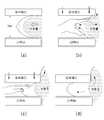
도 1은 유방촬영 X-선 장치의 표준 촬영 방법을 나타내는 개략도로서, 도 1의 (a)는 상하위 촬영을 나타내고, (b)와 (c)는 내외사위 촬영을 나타낸 것이다. 도 1에 도시된 바와 같이, 표준 모드의 경우 좌우 피검체 각각에 대해 CC 및 MLO 촬영을 실시하는데, 예를 들면 우측 피검체를 RCC(Rt. Cranio-Caudal) 및 RMLO(Rt. Medio-Lateral Oblique)를 포함하여 기본 2장 촬영하고, 좌측 피검체를 LCC(Lt. Cranio-Caudal) 및 LMLO(Lt. Medio-Lateral Oblique)를 포함하여 2장 촬영을 기본으로 환자 1인당 4장을 실시하고 필요시 추가 촬영을 한다.Fig. 1 is a schematic view showing a standard photographing method of a mammography X-ray apparatus. Fig. 1 (a) shows a top-bottom photograph, and Fig. 1 (b) and Fig. As shown in FIG. 1, in the case of the standard mode, CC and MLO photographs are performed for each of the left and right subjects. For example, the right side is divided into RCC (Rt. Cranio-Caudal) and RMLO (Rt. Medio-Lateral Oblique ), And the left-side subject is subjected to four sheets per patient based on two shots, including LCC (Lt.Cranio-Caudal) and LMLO (Lt.Mioio-Lateral Oblique) Shoot additional shots.
그러나, 인체의 흉곽은 곡면으로 이루어진데 반하여, 피검체를 압박하는 종래의 압박대 패들은 피검자의 흉부와 접촉하는 선단부가 직선으로 이루어져 있으므로, 압박대 패들을 이용한 피검체의 압박시 피검체의 근위부(흉부측 부위) 양측이 충분히 압박되지 않는 문제가 있으며, 이로 인해 해당 부위의 진단범위의 감소와 압박의정확도가 떨어지는 문제점이 있다.However, since the conventional chest pads for compressing the subject are formed in a curved shape, the tip of the subject in contact with the chest of the subject is formed in a straight line. Therefore, when the subject is pressed using the pads, There is a problem that both sides of the chest area (thoracic side) are not pressed sufficiently, which results in a decrease in the diagnosis range of the relevant region and a decrease in accuracy of compression.
또한, 피검체 내부에 인공 보형물을 삽입한 피검자의 경우에는 도 2에 도시된 바와 같이 보형물을 흉부측으로 밀어낸 상태로 촬영해야 한다. 그러나, 보형물이 원활하게 밀려나지 않는 경우에는 압박대 패들을 반복적으로 승강시켜가면서 검사자가 직접 손으로 보형물을 흉부측으로 밀어내야 하므로, 유방촬영 X-선 장치의 촬영시간이 길어지고 그에 따라 피검자가 느끼는 고통 및 불편함이 가중될 뿐만 아니라 검사자의 피로도가 증가하는 문제점이 있다.In addition, in the case of a subject having an artificial implant inserted into the body of the subject, the implant should be photographed in a state in which the implant is pushed to the chest side as shown in Fig. However, when the implant is not pushed smoothly, the examiner must manually push the implant to the chest side while repeatedly raising and lowering the pressure pads, so that the shooting time of the mammography X-ray apparatus becomes longer and accordingly, The pain and discomfort are increased, and the fatigue of the examinee is increased.
따라서, 본 발명의 목적은 이와 같은 종래의 문제점을 해결하기 위한 것으로서, 압박대 패들의 선단부가 피검체의 근위부 양측을 충분히 압박하여 촬영 정확도를 향상시킬 수 있는 유방촬영 X-선 장치의 압박 기구 및 이를 포함하는 유방촬영 X-선 장치를 제공함에 있다.SUMMARY OF THE INVENTION It is therefore an object of the present invention to provide a compression mechanism of a mammography X-ray apparatus capable of sufficiently pushing both sides of a proximal portion of a subject to improve imaging accuracy, And a mammography X-ray apparatus including the same.
상기 목적은, 본 발명에 따라, 본체부와, 상기 본체부의 일단부에 배치되어 엑스레이를 조사하는 X 선관(X-ray tube)과, 상기 X 선관과 대면하도록 상기 본체부의 타단부에 배치된 디텍터를 구비한 유방촬영 X-선 장치의 압박 기구에 있어서, 상기 본체부와 나란한 제1축 방향으로 이동하면서 디텍터의 상측에 배치되는 피검체를 선택적으로 압박하되, 피검자의 흉부와 접촉하는 선단부 중앙에는 오목한 곡면부가 함몰 형성되고, 상기 선단부 양측에는 피검체의 근위부 양측을 압박하는 가압부가 형성되는 것을 특징으로 하는 유방촬영 X-선 장치의 압박 기구에 의해 달성된다.According to an aspect of the present invention, there is provided an X-ray imaging apparatus including a main body, an X-ray tube disposed at one end of the main body for irradiating an X-ray, a detector disposed at the other end of the main body, And a pressing member for pressing the subject placed on the upper side of the detector while moving in the first axial direction in parallel with the body portion, wherein the distal end portion of the subject, which is in contact with the chest of the subject, And a pressing portion for pressing both sides of the proximal portion of the subject is formed on both sides of the distal end portion.
본 발명은 본체부에 연결되는 프레임;과, 상기 프레임으로부터 상기 제1축과 교차하는 제2축 방향으로 이동 가능하게 배치되는 압박대 패들; 및 상기 압박대 패들과 프레임의 조립부위에 형성되어 상기 압박대 패들의 제2축 방향 이동을 안내하는 가이드부;를 포함하는 것이 바람직하다.The present invention provides a pneumatic tire comprising: a frame connected to a main body; a pushing paddle movably arranged in a second axis direction intersecting with the first axis from the frame; And a guide portion formed at an assembly portion between the pushing paddle and the frame to guide the pushing paddles in the second axial direction.
또한, 상기 프레임은 제2축 방향을 따라 연장되어 압박대 패들의 양 측면을 지지하는 복수의 지지암을 포함하고, 상기 가이드부는 지지암과 압박대 패들의 서로 마주하는 면에 배치되는 것이 바람직하다.In addition, it is preferable that the frame includes a plurality of support arms extending along the second axial direction to support both sides of the pushing paddles, and the guide portions are disposed on the faces of the support arms and the pushing paddles facing each other .
또한, 상기 가이드부는 제2축 방향을 따라 연장되어 서로 맞물리는 안내레일과 안내돌기를 포함하는 것이 바람직하다.Preferably, the guide portion includes guide rails and guide protrusions extending along the second axis direction and meshed with each other.
또한, 상기 압박대 패들에 착탈 가능하게 조립되는 고정틀;을 더 포함하는 것이 바람직하다.It is further preferable that the apparatus further comprises a fixing frame detachably assembled to the pressing paddle.
또한, 상기 가이드부는 제2축 방향을 따라 연장되는 안내봉과, 상기 안내봉에 대응하는 위치에 형성되어 안내봉이 삽입된 상태로 안내봉의 축방향 이동을 안내하는 안내홀을 포함하는 것이 바람직하다.Preferably, the guide portion includes a guide bar extending along the second axis direction, and a guide hole formed at a position corresponding to the guide bar and guiding the axial movement of the guide bar in a state where the guide bar is inserted.
또한, 상기 프레임과 압박대 패들의 사이에 개재되어 상기 압박대 패들을 피검자의 흉부를 향하는 제2축 방향으로 탄성지지하는 탄성기구;를 더 포함하는 것이 바람직하다.It is also preferable that the apparatus further includes an elastic mechanism interposed between the frame and the pushing paddles to elastically support the pushing paddles in a second axial direction toward the subject's chest.
본 발명의 목적은 상기 압박 기구;를 포함하는 유방촬영 X-선 장치에 의해서도 달성될 수 있다.The object of the present invention can also be achieved by a mammography X-ray apparatus including the above-described pressing mechanism.
본 발명에 따르면, 압박대 패들의 선단부에 오목한 곡면부가 형성되어 압박대 패들의 선단부가 피검체의 근위부 양측을 충분히 압박하여 촬영 정밀도를 향상시킬 수 있는 유방촬영 X-선 장치의 압박 기구 및 이를 포함하는 유방촬영 X-선 장치 제공된다.According to the present invention, a concave curved surface portion is formed at the distal end portion of the pushing paddles, so that the tip portion of the pushing paddles sufficiently presses both sides of the proximal portion of the subject to improve the imaging accuracy and the pushing mechanism of the mammography X- A mammography X-ray device is provided.
도 1은 유방촬영 X-선 장치의 표준 촬영 방법을 나타내는 개략도,
도 2는 인공 보형물이 삽입된 피검체의 촬영 방법을 나타내는 개략도,
도 3은 본 발명의 압박기구를 포함하는 유방촬영 X-선 장치의 개략구성도,
도 4는 본 발명 유방촬영 X-선 장치의 압박 기구의 사시도,
도 5는 본 발명 유방촬영 X-선 장치의 압박 기구의 분해사시도,
도 6은 도 4의 A-A'선 단면도,
도 7은 도 4의 B-B'선 단면도,
도 8은 본 발명 유방촬영 X-선 장치의 압박 기구의 작용단면도이다.BRIEF DESCRIPTION OF THE DRAWINGS FIG. 1 is a schematic view showing a standard imaging method of a mammography X-
2 is a schematic view showing a photographing method of a test object inserted with a prosthetic implant,
Fig. 3 is a schematic configuration diagram of a mammography X-ray apparatus including a pressing mechanism of the present invention,
Fig. 4 is a perspective view of a pushing mechanism of the mammography X-
Fig. 5 is an exploded perspective view of the compression mechanism of the mammography X-
6 is a cross-sectional view along the line A-A 'in Fig. 4,
7 is a sectional view taken along the line B-B 'in Fig. 4,
Fig. 8 is a functional sectional view of the compression mechanism of the mammography X-ray apparatus of the present invention.
설명에 앞서, 여러 실시예에 있어서, 동일한 구성을 가지는 구성요소에 대해서는 동일한 부호를 사용하여 대표적으로 제1실시예에서 설명하고, 그 외의 실시예에서는 제1실시예와 다른 구성에 대해서 설명하기로 한다.Prior to the description, components having the same configuration are denoted by the same reference numerals as those in the first embodiment. In other embodiments, configurations different from those of the first embodiment will be described do.
이하, 첨부한 도면을 참조하여 본 발명의 제1실시예에 따른 유방촬영 X-선 장치의 압박 기구에 대하여 상세하게 설명한다.Hereinafter, a compression mechanism of the mammography X-ray apparatus according to the first embodiment of the present invention will be described in detail with reference to the accompanying drawings.
첨부도면 중, 도 3은 본 발명의 압박기구를 포함하는 유방촬영 X-선 장치의 개략구성도이다.In the accompanying drawings, FIG. 3 is a schematic configuration diagram of a mammography X-ray apparatus including a pressing mechanism of the present invention.
상기 도면에서 도시하는 바와 같은 본 발명의 압박 기구를 포함하는 유방촬영 X-선 장치는 본체부(110)와, X 선관(X-ray tube)(120)과, 디텍터(130) 및 압박 기구(140)를 포함하여 구성된다.The mammography X-ray apparatus including the pushing mechanism of the present invention as shown in the drawings includes a
상기 본체부(110)는 장치의 지지 칼럼(미도시)에 회전 가능하게 연결되는 것으로서, 도 3에 도시된 바와 같이 대략 'C'자의 형태로 이루어질 수 있다. 상기 본체부(110)의 피검자와 마주하는 면에는 압박 기구(140)의 이동을 안내하는 레일홈(미도시)이 길이방향으로 형성되고, 내부에는 레일홈을 따라 압박 기구(140)를 이동시키는 구동수단(미도시)이 마련된다.The
상기 본체부(110)의 일단부에는 타단부를 향해 엑스레이를 조사하는 제너레이터(이하, 'X 선관(X-ray tube)'이라고 함)가 배치되고, 타단부에는 X 선관(X-ray tube)(120)과 대면하여 배치된 디텍터(130)가 배치된다.An X-ray tube is disposed at one end of the
X 선관(X-ray tube)(120)은 음극에서 발생된 음전자를 양극의 금속 타깃(target)에 충돌시켜 엑스레이를 발생시키는 것으로서, 엑스레이의 조사 방향 또는 조사 면적을 제어하는 콜리메이터(collimator)로 구성되어 있다.An
디텍터(130)는 본체부(110)의 타단부에 고정되어 상기 X 선관(X-ray tube)(120)으로부터 조사되어 피검체를 통과한 엑스레이를 수광하여 영상을 얻기 위한 수단으로, 피검체를 지지하는 지지부의 내부에 배치될 수 있다. 즉, 상기 디텍터(130) 상에 피검체를 올려놓은 후 상기 압박 기구(140)로 피검체를 가압함으로써, 상기 디텍터(130)와 압박 기구(140) 사이에서 피검체가 압박되도록 하고, 상기 X 선관(X-ray tube)(120)과 디텍터(130)를 이용해 압박된 상태의 피검체를 촬영하게 된다. 디텍터(130)는 엑스레이의 입사량에 비례한 위치별 전기신호를 생성하고, 전기신호와 위치정보를 읽어 영상처리 알고리즘으로 처리하여 피검체의 엑스레이 영상을 얻을 수 있다. 이때, 디텍터(130)에는 엑스레이의 변환 방식에 따라 별도의 중간 단계 없이 엑스레이로부터 직접 전기적 신호를 획득하는 직접 변환 방식이나 엑스레이를 가시광선으로 변환하여 가시광선에 의해 간접적으로 전기적 신호를 얻는 간접 변환 방식 등 일반적인 기술 내용이 폭넓게 적용될 수 있다.The
상기와 같은 유방촬영 X-선 장치에 적용되는 본 발명의 압박 기구(140)는 상기 본체부(110)의 길이방향과 나란한 제1축 방향으로 이동 가능하게 배치되어 디텍터(130)와의 사이에 배치되는 피검체를 선택적으로 압박하는 것이다.The pushing
이하에서는 상기 압박 기구(140)에 대하여 도 4 내지 도 5를 참조하여 더욱 상세하게 설명한다.Hereinafter, the
첨부도면 중, 도 4는 본 발명 유방촬영 X-선 장치의 압박 기구의 사시도이고, 도 5는 본 발명 유방촬영 X-선 장치의 압박 기구의 분해사시도이다.In the drawings, FIG. 4 is a perspective view of a pushing mechanism of the mammography X-ray apparatus of the present invention, and FIG. 5 is an exploded perspective view of a pushing mechanism of the mammography X-ray apparatus of the present invention.
상기 압박 기구(140)는 본체부(110) 측에 연결되어 제1축 방향으로 이동하는 프레임(141)과, 상기 프레임(141)으로부터 상기 제1축과 교차하는 제2축 방향으로 이동 가능하게 배치되는 압박대 패들(142)과, 상기 압박대 패들(142)과 프레임(141)의 조립부위에 형성되어 상기 압박대 패들(142)의 제2축 방향 이동을 안내하는 가이드부 및 상기 압박대 패들(142)이 피검자의 흉부를 향하는 방향으로 돌출되도록 일단부는 프레임(141)에 지지되고 타단부는 압박대 패들(142)에 지지되는 스프링과 같은 탄성기구(146)를 포함하여 구성된다.The
상기 프레임(141)은 일단부가 상기 본체부(110)의 구동수단에 연결되며, 타단부에는 한 쌍의 지지암(141a)이 제2축 방향을 따라 연장된다.One end of the
상기 압박대 패들(142)은 피검체의 압박된 상태가 시각적으로 보일 수 있도록 폴리카보네이트(PC; Polycarbonate)와 같은 투명재질로 이루어지며, 피검자의 흉부와 접촉하는 선단부 중앙에는 오목한 곡면부(142a)가 함몰 형성되고, 상기 선단부 양측에는 피검체의 근위부 양측을 압박하는 가압부(142b)가 형성된다.The pushing
또한, 압박대 패들(142)은, 대략 'ㄷ'자 형태로 이루어져 압박대 패들(142)의 선단부를 제외한 나머지 측면에 착탈 가능하게 조립되는 고정틀(143)을 포함한다. 상기 압박대 패들(142)의 고정틀(143)은 상기 프레임(141)의 양측 지지암(141a) 사이에 제2축 방향으로 이동 가능하게 수용되며, 상기 프레임(141)으로부터 제2축 방향으로 이동할 수 있도록 가이드부를 통해 프레임(141)과 연결된다. 상기 고정틀(143)은 내구성이 우수하고 변형률이 작고, 방사선 산란이 적은 알루미늄과 같은 재질로 이루어지는 것이 바람직하다.The
상기 오목한 곡면부(142a)의 함몰 깊이나 가압부(142b)의 넓이는 피검자의 체형에 따라 설계될 수 있으며, 서로 다른 크기의 곡면부(142a)를 갖는 압박대 패들(142)을 복수 마련하여 피검자의 체형에 맞는 압박대 패들(142)을 고정틀(143)에 결합하여 사용하는 것도 가능하다.The depressed depth of the concave
이러한 가이드부는 압박대 패들(142)이 제2축 방향으로 안정적으로 이동할 수 있도록, 제1가이드부와 제2가이드부 중 적어도 어느 하나를 포함할 수 있다.The guide portion may include at least one of a first guide portion and a second guide portion so that the pushing
상기 제1가이드부는 지지암(141a)의 고정틀(143)과 마주하는 면에 제2축 방향을 따라 형성된 안내레일(144b)과 고정틀(143)의 지지암(141a)과 마주하는 면에 제2축 방향을 따라 형성되어 상기 안내레일(144b)과 맞물리는 안내돌기(144a)를 포함한다.The first guide part has a
상기 제2가이드부는 상기 압박대 패들(142)의 고정틀(143) 후단부의 중앙 양측에서 제2축 방향을 따라 연장된 복수의 안내봉(145a)과, 상기 프레임(141)의 상기 안내봉(145a)에 대응하는 위치에 각각 형성되어 상기 안내봉(145a)이 삽입된 상태로 안내봉(145a)의 축방향 이동을 안내하는 안내홀(145b)을 포함한다.The second guide portion includes a plurality of
상기 가이드부에 의해 프레임(141)에 연결된 압박대 패들(142)은 압박대 패들(142)의 양측에서 제2축 방향으로 서로 맞물리는 제1가이드부와, 압박대 패들(142)의 후단부에서 제2축 방향으로 서로 맞물리는 제2가이드부를 통해 제1축 방향으로 압력을 효과적으로 전달할 수 있으며, 프레임(141)과 압박대 패들(142)의 연결부위 중 일영역에 제1축 방향의 하중이 집중되어 연결부위가 쉽게 손상되는 것을 방지할 수 있다.The pushing
상기 탄성기구(146)는 상기 압박대 패들(142)이 고정된 고정틀(143)을 피검자의 흉부를 향하는 방향으로 돌출되도록 탄성지지하는 것으로서, 상기 제2가이드부의 안내봉(145a)에 삽입되어 일단부가 프레임(141)에 지지되고 타단부는 고정틀(143)에 지지되는 코일 스프링의 형태로 이루어질 수 있다. 한편, 본 실시예에서는 상기 탄성기구(146)가 코일 스프링으로 이루어져 안내봉(145a) 상에 위치하는 것으로 예를 들어 설명하였으나 이에 한정하는 것은 아니며, 압박대 패들(142)을 피검자를 향해 돌출시키는 방향으로 탄성지지할 수 있는 다른 형태의 탄성수단이 적용되는 것도 가능하다.The
지금부터는 상술한 압박 기구를 이용한 유방촬영 과정에 대하여 설명한다.Hereinafter, the breast imaging process using the above-described pressing mechanism will be described.
첨부도면 중, 도 6은 도 4의 A-A'선 단면도이고, 도 7은 도 4의 B-B'선 단면도이고, 도 8은 본 발명 유방촬영 X-선 장치의 압박 기구의 작용단면도이다.6 is a sectional view taken along the line A-A 'in FIG. 4, FIG. 7 is a sectional view taken along the line B-B' in FIG. 4, and FIG. 8 is a functional sectional view of the compression mechanism of the mammography X- .
상기 도면에 도시된 바와 같이, 본 발명에 따른 압박 기구(140)의 압박대 패들(142)은 고정틀(143)에 고정된 상태에서, 고정틀(143)과 프레임(141)의 양 측면에 각각 형성된 제1가이드부와 고정틀(143)과 프레임(141)의 후단부에 각각 형성된 제2가이드부에 의해 제2축 방향으로의 이동이 안내된다.The pushing
구체적으로, 지지암(141a)과 고정틀(143)의 서로 마주하는 면에 각각 형성되어 제1가이드부를 구성하는 안내돌기(144a)와 안내레일(144b)은 제2축 방향으로의 이동이 가능하도록 상호 맞물리고, 고정틀(143)의 후단부와 프레임(141)의 서로 마주하는 면에 각각 형성되어 제2가이드부를 구성하는 안내봉(145a)과 안내홀(145b)은 서로 결합한 삽입된 상태에서 제2축 방향으로의 이동이 안내된다.Specifically, the
상기 제1가이드부는 압박대 패들(142)의 양 측면에 배치되고, 제2가이드부는 압박대 패들(142)의 후단부에 배치되어 있으므로, 상기 압박대 패들(142)이 프레임(141)으로부터 제2축 방향으로 안정적으로 이동할 수 있게 된다. 또한, 본체부(110)를 따라 제1축 방향으로 이동하는 프레임(141)측으로부터 압박대 패들(142)로 전달되어 피검체를 압박하는 제1축 방향으로의 압력이 제1가이드부와 제2가이드부를 통해 분산 지지되므로 프레임(141)과 압박대 패들(142)의 연결부위가 변형되거나 파손되는 것을 방지할 수 있다.Since the first guide portion is disposed on both sides of the pushing
피검체를 촬영하기 위해서는, 피검체를 디텍터(130)와 압박 기구(140) 사이에 위치시킨 다음, 피검자의 흉부를 디텍터(130)와 압박대 패들(142)의 선단부에 각각 밀착시켜야 한다.The subject is placed between the
이때, 상기 압박대 패들(142)은 프레임(141)과 고정틀(143) 사이에 개재되는 탄성기구(146)에 의해 피검자를 향하는 돌출방향으로 탄성지지되어 있으므로, 압박대 패들(142)의 선단부에 위치한 오목한 곡면부(142a) 전면이 피검자의 흉부에 밀착된 상태가 된다. 이러한 상태에서, 상기 압박대 패들(142)이 제1축 방향으로 이동하면서 피검체를 압박하는 과정에서, 압박대 패들(142)의 선단부 양측에 마련된 가압부(142b)가 피검체의 근위부(흉부측 부위) 양측을 압박하게 되므로, 피검체의 조직이 검사영역의 외측으로 빠져나가는 것을 최소화할 수 있다.Since the
또한, 피검체 내부에 인공 보형물을 삽입한 피검자의 경우에는 보형물을 흉부측으로 밀어낸 상태로 촬영해야만 보형물에 의해 병변 및 미세석회화가 가려지는 것을 방지할 수 있다.In addition, in the case of a subject having a prosthetic implant inserted into the subject, it is necessary to photograph the implant in a state in which the implant is pushed toward the thoracic side to prevent lesions and microcalcifications from being obscured by the implant.
즉, 인공 보형물을 삽입한 피검자를 대상으로 하는 경우에는 피검자의 피검체를 압박대 패들(142)과 디텍터(130) 사이에 위치시키고, 앞서 설명한 것과 마찬가지로 압박 기구(140)를 제1축 방향으로 이동시켜 보형물이 삽입된 피검체를 압박한다.That is, when the examinee having the inserted prosthesis is to be examined, the subject of the subject is placed between the pushing
이때, 압박대 패들(142)이 제1축 방향으로 이동하여 피검체의 상부를 압박하는 과정에서, 도 6 및 도 8과 같이 압박대 패들(142)을 제2축 방향으로 왕복 이동시키면, 압박대 패들(142)이 피검체 내부의 인공 보형물을 흉부측으로 밀어낼 수 있다. 이때, 압박대 패들(142)의 선단부가 보형물을 흉부측으로 탄성적으로 지지하는 상태가 되므로, 보형물이 압박대 패들(142)과 디텍터(130) 사이의 촬영 영역으로 진입하는 것을 방지할 수 있다. 즉, 보형물을 흉부측으로 원활하게 밀어낼 수 있으므로 맘모그래피 장치의 촬영 시간을 단축하고, 피검자의 불편함 및 검사자의 피로도를 최소화할 수 있다.6 and 8, when the pushing
아울러, 상기 압박대 패들(142)의 선단부에 형성된 오목한 곡면부(142a)에 의해 인공 보형물이 배치된 영역으로의 압력이 양측으로 분산되므로 피검자가 느끼는 고통 및 불편함을 최소화할 수 있다.In addition, the concave
상기와 같은 본 발명은 다음과 같은 유용성(활용가치)을 제공한다.The present invention as described above provides the following usefulness (utility value).
1) 일반적으로 모든 피검자를 대상으로 할 수 있으며, 진단 면적을 기존 압박대보다 증가시킬 수 있다.1) In general, it is possible to target all subjects, and the diagnosis area can be increased more than the conventional pressure.
2) 성형 보형물 환자에게도 효율적으로 사용할 수 있다.2) It can be used effectively for patients with molded implants.
3) 기존 압박 기구에서 미비한 내측과 외측의 유방부분을 포함시킬 수 있다.3) It is possible to include missing inner and outer breast parts in conventional compression mechanism.
4) 탄성기구의 작용으로 압박대 패들을 흉곽에 최대로 밀착할 수 있어 검사부위와 면적이 증가된다.4) By the action of the elastic mechanism, it is possible to maximally adhere the compression paddle to the chest wall, thereby increasing the area and area of the test.
5) 본 발명에 따른 압박 기구는 기존에 사용하고 있는 모든 유방촬영장치에 적용할 수 있으므로 호환성이 우수하며 경제적인 면에서 가치를 높일 수 있다.
5) Since the compression mechanism according to the present invention can be applied to all the mammography apparatuses used in the past, it is excellent in compatibility and can be increased in economic value.
본 발명의 권리범위는 상술한 실시예에 한정되는 것이 아니라 첨부된 특허청구범위 내에서 다양한 형태의 실시예로 구현될 수 있다. 특허청구범위에서 청구하는 본 발명의 요지를 벗어남이 없이 당해 발명이 속하는 기술 분야에서 통상의 지식을 가진 자라면 누구든지 변형 가능한 다양한 범위까지 본 발명의 청구범위 기재의 범위 내에 있는 것으로 본다.The scope of the present invention is not limited to the above-described embodiments, but may be embodied in various forms of embodiments within the scope of the appended claims. It will be understood by those skilled in the art that various changes in form and details may be made therein without departing from the spirit and scope of the present invention as defined by the appended claims.
110:본체부, 120:X 선관(X-ray tube), 130:디텍터,
140:압박기구, 141:프레임, 141a:지지암,
142:압박대 패들, 142a:곡면부, 142b:가압부,
143:고정틀, 144a:안내돌기, 144b:안내홈,
145a:안내봉, 145b:안내홀, 146:탄성기구110: body part, 120: X-ray tube, 130: detector,
140: pressing mechanism, 141: frame, 141a: supporting arm,
142: pressing paddle, 142a: curved portion, 142b: pressing portion,
143: fixed frame, 144a: guide projection, 144b: guide groove,
145a: guide rod, 145b: guide hole, 146: elastic mechanism
Claims (8)
Translated fromKorean본체부에 연결되는 프레임;
상기 프레임으로부터 본체부와 나란한 제1축과 교차하는 제2축 방향으로 이동 가능하게 배치되는 압박대 패들; 및
상기 압박대 패들과 프레임의 조립부위에 형성되어 상기 압박대 패들의 제2축 방향 이동을 안내하는 가이드부;를 포함하며,
상기 압박대 패들은,
제1축 방향으로 이동하면서 디텍터의 상측에 배치되는 피검체를 선택적으로 압박하되,
피검자의 흉부와 접촉하는 선단부 중앙에는 오목한 곡면부가 함몰 형성되고,
상기 선단부 양측에는 피검체의 근위부 양측을 압박하는 가압부가 형성되는 것을 특징으로 하는 유방촬영 X-선 장치의 압박 기구.Ray tube device having a body part, an X-ray tube disposed at one end of the body part to irradiate an X-ray, and a detector disposed at the other end of the body part to face the X- In the pressing mechanism of the present invention,
A frame connected to the body portion;
A pushing paddle movably arranged in a second axial direction intersecting with the first axis parallel to the body portion from the frame; And
And a guide portion formed at an assembly portion of the pushing paddle and the frame to guide a movement of the pushing paddles in a second axial direction,
The pusher paddles,
Selectively pushing a subject disposed on an upper side of the detector while moving in a first axis direction,
A concave curved surface portion is formed at the center of the tip of the subject in contact with the chest,
And a pressing portion for pressing both sides of the proximal portion of the subject is formed on both sides of the distal end portion.
상기 프레임은 제2축 방향을 따라 연장되어 압박대 패들의 양 측면을 지지하는 복수의 지지암을 포함하고, 상기 가이드부는 지지암과 압박대 패들의 서로 마주하는 면에 배치되는 유방촬영 X-선 장치의 압박 기구.3. The method of claim 2,
Wherein the frame includes a plurality of support arms extending along a second axial direction to support both sides of the pusher paddles, Device for pressing.
상기 가이드부는 제2축 방향을 따라 연장되어 서로 맞물리는 안내레일과 안내돌기를 포함하는 유방촬영 X-선 장치의 압박 기구.The method of claim 3,
Wherein the guide portion includes guide rails and guide projections extending along a second axial direction and engaged with each other.
상기 압박대 패들에 착탈 가능하게 조립되는 고정틀;을 더 포함하는 유방촬영 X-선 장치의 압박 기구.5. The method of claim 4,
And a fixing frame detachably assembled to the pushing paddle.
상기 가이드부는 제2축 방향을 따라 연장되는 안내봉과, 상기 안내봉에 대응하는 위치에 형성되어 안내봉이 삽입된 상태로 안내봉의 축방향 이동을 안내하는 안내홀을 포함하는 유방촬영 X-선 장치의 압박 기구.3. The method of claim 2,
Wherein the guide portion includes a guide bar extending along a second axis direction and a guide hole formed at a position corresponding to the guide bar and guiding the axial movement of the guide bar in a state where the guide bar is inserted Compression mechanism.
상기 프레임과 압박대 패들의 사이에 개재되어 상기 압박대 패들을 피검자의 흉부를 향하는 제2축 방향으로 탄성지지하는 탄성기구;를 더 포함하는 유방촬영 X-선 장치의 압박 기구.7. The method according to any one of claims 2 to 6,
And a resilient mechanism interposed between the frame and the pusher pads to elastically support the pusher paddles in a second axial direction toward the subject's chest.
Priority Applications (1)
| Application Number | Priority Date | Filing Date | Title |
|---|---|---|---|
| KR1020150049129AKR101690409B1 (en) | 2015-04-07 | 2015-04-07 | Compression paddle device of mammographic x-ray equipment, mammographic x-ray equipment comprising the same |
Applications Claiming Priority (1)
| Application Number | Priority Date | Filing Date | Title |
|---|---|---|---|
| KR1020150049129AKR101690409B1 (en) | 2015-04-07 | 2015-04-07 | Compression paddle device of mammographic x-ray equipment, mammographic x-ray equipment comprising the same |
Publications (2)
| Publication Number | Publication Date |
|---|---|
| KR20160120075A KR20160120075A (en) | 2016-10-17 |
| KR101690409B1true KR101690409B1 (en) | 2016-12-27 |
Family
ID=57250212
Family Applications (1)
| Application Number | Title | Priority Date | Filing Date |
|---|---|---|---|
| KR1020150049129AActiveKR101690409B1 (en) | 2015-04-07 | 2015-04-07 | Compression paddle device of mammographic x-ray equipment, mammographic x-ray equipment comprising the same |
Country Status (1)
| Country | Link |
|---|---|
| KR (1) | KR101690409B1 (en) |
Families Citing this family (2)
| Publication number | Priority date | Publication date | Assignee | Title |
|---|---|---|---|---|
| CN111938679B (en)* | 2020-09-18 | 2025-05-13 | 暴云锋 | A new breast X-ray machine |
| CN114391863B (en)* | 2022-01-17 | 2025-08-26 | 马静林 | A breast positioning and compression device for breast examination |
Citations (3)
| Publication number | Priority date | Publication date | Assignee | Title |
|---|---|---|---|---|
| JP2007097827A (en) | 2005-10-04 | 2007-04-19 | Toshiba Corp | Breast X-ray machine |
| JP2012024165A (en) | 2010-07-20 | 2012-02-09 | Fujifilm Corp | Radiographic image capturing device and compression paddle |
| KR101168308B1 (en) | 2011-04-04 | 2012-07-24 | (주)비멤스 | Controller of breast pressing unit for mammography |
Family Cites Families (1)
| Publication number | Priority date | Publication date | Assignee | Title |
|---|---|---|---|---|
| KR101141041B1 (en)* | 2010-05-12 | 2012-05-03 | 한국전기연구원 | Breast Cancer Diagnostic Apparatus |
- 2015
- 2015-04-07KRKR1020150049129Apatent/KR101690409B1/enactiveActive
Patent Citations (3)
| Publication number | Priority date | Publication date | Assignee | Title |
|---|---|---|---|---|
| JP2007097827A (en) | 2005-10-04 | 2007-04-19 | Toshiba Corp | Breast X-ray machine |
| JP2012024165A (en) | 2010-07-20 | 2012-02-09 | Fujifilm Corp | Radiographic image capturing device and compression paddle |
| KR101168308B1 (en) | 2011-04-04 | 2012-07-24 | (주)비멤스 | Controller of breast pressing unit for mammography |
Also Published As
| Publication number | Publication date |
|---|---|
| KR20160120075A (en) | 2016-10-17 |
Similar Documents
| Publication | Publication Date | Title |
|---|---|---|
| JP3187716U (en) | Integrated multi-mode mammography / tomosynthesis x-ray system and method | |
| JP4857070B2 (en) | Mammography X-ray CT system | |
| US7697660B2 (en) | Apparatus and method for cone beam computed tomography breast imaging | |
| US7885378B2 (en) | Imaging system and related techniques | |
| KR101384601B1 (en) | Digital X-ray Mammography and Diagnosis Method for Breast Cancer | |
| JP4773309B2 (en) | Breast radiation image capturing apparatus and breast radiation image capturing method | |
| JP2010069241A (en) | Tomographic breast imaging system | |
| WO2014157794A1 (en) | Mammography device and subject shooting method using same | |
| CN105228526B (en) | Mammography apparatus | |
| CN102883663A (en) | Compression plate for tomosynthesis | |
| JP2010158257A (en) | Device and system for picking up radiation image | |
| KR101690409B1 (en) | Compression paddle device of mammographic x-ray equipment, mammographic x-ray equipment comprising the same | |
| US20080037703A1 (en) | Three dimensional breast imaging | |
| KR102083820B1 (en) | Mammography apparatus and position alingement control method thereof | |
| CN105208936B (en) | Mammography apparatus and the method for controlling its position alignment | |
| KR20240013158A (en) | Imaging devices and imaging methods | |
| JP2007289225A (en) | Breast imaging method and apparatus | |
| KR102083821B1 (en) | Mommography apparatus and method of photographing object using the same | |
| JP2007268033A (en) | Radiography system and radiography method | |
| KR102080176B1 (en) | Mammography apparatus | |
| KR20140118423A (en) | Mammography apparatus | |
| KR20130014338A (en) | Image diagnosis device including x-ray image tomosynthesis device and photoacoustic image device and image diagnosis method thereof | |
| KR102014861B1 (en) | Digital mammography apparatus | |
| Varjonen et al. | Breast positioning system for full field digital mammography and digital breast tomosynthesis system |
Legal Events
| Date | Code | Title | Description |
|---|---|---|---|
| A201 | Request for examination | ||
| PA0109 | Patent application | Patent event code:PA01091R01D Comment text:Patent Application Patent event date:20150407 | |
| PA0201 | Request for examination | ||
| E902 | Notification of reason for refusal | ||
| PE0902 | Notice of grounds for rejection | Comment text:Notification of reason for refusal Patent event date:20160407 Patent event code:PE09021S01D | |
| PG1501 | Laying open of application | ||
| E701 | Decision to grant or registration of patent right | ||
| PE0701 | Decision of registration | Patent event code:PE07011S01D Comment text:Decision to Grant Registration Patent event date:20161213 | |
| GRNT | Written decision to grant | ||
| PR0701 | Registration of establishment | Comment text:Registration of Establishment Patent event date:20161221 Patent event code:PR07011E01D | |
| PR1002 | Payment of registration fee | Payment date:20161221 End annual number:3 Start annual number:1 | |
| PG1601 | Publication of registration | ||
| FPAY | Annual fee payment | Payment date:20200108 Year of fee payment:4 | |
| PR1001 | Payment of annual fee | Payment date:20200108 Start annual number:4 End annual number:4 | |
| PR1001 | Payment of annual fee | Payment date:20201216 Start annual number:5 End annual number:5 | |
| PR1001 | Payment of annual fee | Payment date:20211215 Start annual number:6 End annual number:6 | |
| PR1001 | Payment of annual fee |