KR101688241B1 - Locking polyaxial ball and socket fastener - Google Patents
Locking polyaxial ball and socket fastenerDownload PDFInfo
- Publication number
- KR101688241B1 KR101688241B1KR1020117013596AKR20117013596AKR101688241B1KR 101688241 B1KR101688241 B1KR 101688241B1KR 1020117013596 AKR1020117013596 AKR 1020117013596AKR 20117013596 AKR20117013596 AKR 20117013596AKR 101688241 B1KR101688241 B1KR 101688241B1
- Authority
- KR
- South Korea
- Prior art keywords
- retaining ring
- socket
- ball
- spherical connector
- connector
- Prior art date
- Legal status (The legal status is an assumption and is not a legal conclusion. Google has not performed a legal analysis and makes no representation as to the accuracy of the status listed.)
- Expired - Fee Related
Links
Images


Classifications
- A—HUMAN NECESSITIES
- A61—MEDICAL OR VETERINARY SCIENCE; HYGIENE
- A61B—DIAGNOSIS; SURGERY; IDENTIFICATION
- A61B17/00—Surgical instruments, devices or methods
- A61B17/56—Surgical instruments or methods for treatment of bones or joints; Devices specially adapted therefor
- A61B17/58—Surgical instruments or methods for treatment of bones or joints; Devices specially adapted therefor for osteosynthesis, e.g. bone plates, screws or setting implements
- A61B17/68—Internal fixation devices, including fasteners and spinal fixators, even if a part thereof projects from the skin
- A61B17/70—Spinal positioners or stabilisers, e.g. stabilisers comprising fluid filler in an implant
- A61B17/7001—Screws or hooks combined with longitudinal elements which do not contact vertebrae
- A61B17/7035—Screws or hooks, wherein a rod-clamping part and a bone-anchoring part can pivot relative to each other
- A61B17/7037—Screws or hooks, wherein a rod-clamping part and a bone-anchoring part can pivot relative to each other wherein pivoting is blocked when the rod is clamped
- A—HUMAN NECESSITIES
- A61—MEDICAL OR VETERINARY SCIENCE; HYGIENE
- A61B—DIAGNOSIS; SURGERY; IDENTIFICATION
- A61B17/00—Surgical instruments, devices or methods
- A61B17/56—Surgical instruments or methods for treatment of bones or joints; Devices specially adapted therefor
- A—HUMAN NECESSITIES
- A61—MEDICAL OR VETERINARY SCIENCE; HYGIENE
- A61B—DIAGNOSIS; SURGERY; IDENTIFICATION
- A61B17/00—Surgical instruments, devices or methods
- A61B17/56—Surgical instruments or methods for treatment of bones or joints; Devices specially adapted therefor
- A61B17/58—Surgical instruments or methods for treatment of bones or joints; Devices specially adapted therefor for osteosynthesis, e.g. bone plates, screws or setting implements
- A61B17/68—Internal fixation devices, including fasteners and spinal fixators, even if a part thereof projects from the skin
- A61B17/70—Spinal positioners or stabilisers, e.g. stabilisers comprising fluid filler in an implant
- A61B17/7001—Screws or hooks combined with longitudinal elements which do not contact vertebrae
- A61B17/7032—Screws or hooks with U-shaped head or back through which longitudinal rods pass
- A—HUMAN NECESSITIES
- A61—MEDICAL OR VETERINARY SCIENCE; HYGIENE
- A61B—DIAGNOSIS; SURGERY; IDENTIFICATION
- A61B17/00—Surgical instruments, devices or methods
- A61B17/56—Surgical instruments or methods for treatment of bones or joints; Devices specially adapted therefor
- A61B17/58—Surgical instruments or methods for treatment of bones or joints; Devices specially adapted therefor for osteosynthesis, e.g. bone plates, screws or setting implements
- A61B17/68—Internal fixation devices, including fasteners and spinal fixators, even if a part thereof projects from the skin
- A61B17/70—Spinal positioners or stabilisers, e.g. stabilisers comprising fluid filler in an implant
- A61B17/7001—Screws or hooks combined with longitudinal elements which do not contact vertebrae
- A61B17/7035—Screws or hooks, wherein a rod-clamping part and a bone-anchoring part can pivot relative to each other
- A61B17/7038—Screws or hooks, wherein a rod-clamping part and a bone-anchoring part can pivot relative to each other to a different extent in different directions, e.g. within one plane only
- A—HUMAN NECESSITIES
- A61—MEDICAL OR VETERINARY SCIENCE; HYGIENE
- A61B—DIAGNOSIS; SURGERY; IDENTIFICATION
- A61B17/00—Surgical instruments, devices or methods
- A61B17/56—Surgical instruments or methods for treatment of bones or joints; Devices specially adapted therefor
- A61B17/58—Surgical instruments or methods for treatment of bones or joints; Devices specially adapted therefor for osteosynthesis, e.g. bone plates, screws or setting implements
- A61B17/68—Internal fixation devices, including fasteners and spinal fixators, even if a part thereof projects from the skin
- A61B17/84—Fasteners therefor or fasteners being internal fixation devices
- A61B17/86—Pins or screws or threaded wires; nuts therefor
- A—HUMAN NECESSITIES
- A61—MEDICAL OR VETERINARY SCIENCE; HYGIENE
- A61F—FILTERS IMPLANTABLE INTO BLOOD VESSELS; PROSTHESES; DEVICES PROVIDING PATENCY TO, OR PREVENTING COLLAPSING OF, TUBULAR STRUCTURES OF THE BODY, e.g. STENTS; ORTHOPAEDIC, NURSING OR CONTRACEPTIVE DEVICES; FOMENTATION; TREATMENT OR PROTECTION OF EYES OR EARS; BANDAGES, DRESSINGS OR ABSORBENT PADS; FIRST-AID KITS
- A61F2/00—Filters implantable into blood vessels; Prostheses, i.e. artificial substitutes or replacements for parts of the body; Appliances for connecting them with the body; Devices providing patency to, or preventing collapsing of, tubular structures of the body, e.g. stents
- A61F2/02—Prostheses implantable into the body
- A61F2/30—Joints
- A61F2/44—Joints for the spine, e.g. vertebrae, spinal discs
Landscapes
- Health & Medical Sciences (AREA)
- Orthopedic Medicine & Surgery (AREA)
- Life Sciences & Earth Sciences (AREA)
- Surgery (AREA)
- Neurology (AREA)
- Engineering & Computer Science (AREA)
- Biomedical Technology (AREA)
- General Health & Medical Sciences (AREA)
- Veterinary Medicine (AREA)
- Heart & Thoracic Surgery (AREA)
- Public Health (AREA)
- Animal Behavior & Ethology (AREA)
- Molecular Biology (AREA)
- Medical Informatics (AREA)
- Nuclear Medicine, Radiotherapy & Molecular Imaging (AREA)
- Cardiology (AREA)
- Oral & Maxillofacial Surgery (AREA)
- Transplantation (AREA)
- Vascular Medicine (AREA)
- Surgical Instruments (AREA)
Abstract
Translated fromKoreanDescription
Translated fromKorean본 발명은 볼 및 소켓 패스너에 관한 것으로서, 특히 척추 임플란트로서 사용하기에 적합한 다축구성 볼 및 소켓 패스너에 관한 것이다.The present invention relates to ball and socket fasteners, and more particularly to multi-axial ball and socket fasteners suitable for use as spinal implants.
다양한 볼 및 소켓 패스너가 있지만, 특정 제품에 대해 적용될 때, 볼 및 소켓은 효율적이 되기 위하여 최소 요구조건을 충족시켜야 한다. 예를 들어, 척추 병리학 분야에서는, 새로 개발된 척추 고정장치들은 의료 분야에서 주된 진전을 나타내고 있다. 수술적 임플란트 고정 시스템들은 외상 또는 외상이 성장되는 동안 부적절하게 변형되는 결과로 발생되는 문제점들을 포함하여 통상 다양한 등 구조(back structure) 문제점들을 교정하기 위해 사용된다. 일반적으로 사용되는 고정 시스템은 환자의 척추에 대해 원하는 방향으로 정렬되는 하나 이상의 고정 로드(stabilizing rod)를 사용하게 된다. 고정 나사들이 환자의 척추 뼈(spinal bone) 내로 삽입되고 일련의 커넥터(connector)들이 로드와 고정장치들을 단단하게 연결하도록 사용된다.There are a variety of ball and socket fasteners, but when applied to a particular product, the ball and socket must meet the minimum requirements to be efficient. For example, in the field of spinal pathology, newly developed spinal fixation devices represent a major advance in the medical field. Surgical implant fixation systems are commonly used to correct a variety of back structure problems, including problems resulting from inadequate deformation during trauma or trauma. A commonly used fixation system uses one or more stabilizing rods aligned in a desired direction with respect to the patient ' s vertebrae. Fixing screws are inserted into the patient's spinal bone and a series of connectors are used to connect the rods and fasteners tightly.
개인의 척추를 새로 형성할 때(reshaping) 바람직한 곡률(curvature)을 따르게 하기 위해 발생되는 다양한 형태의 어려움들을 수용하기 위하여 다양한 디자인이 있다. 공지되어 있는 임플란트 시스템들은 종종 이러한 문제점들 중 하나만 교정하여 또다시 새로운 문제점들을 만들어 낸다.There are a variety of designs to accommodate the various types of difficulties that arise in order to follow the desired curvature of reshaping an individual's vertebrae. Known implant systems often correct only one of these problems and again create new problems.
위에서 언급한 구성요소들을 뒷받침하기 위해, 모든 척추 임플란트 시스템에서는 일반적으로 골(bone)에 적절하게 고정할 필요성이 존재한다. 이와 같이 고정하기 위해 통상 골 나사(bone screw)가 사용되며, 다축구성 디자인(polyaxial design)을 사용하는 것이 의사가 변형을 최소한으로 하여 개별 환자에게 고정하여 장착할 수 있게 한다는 점에서 매우 효율적인 것으로 입증되어 왔다.To support the above-mentioned components, there is a general need to properly fix the bone in all spinal implant systems. A bone screw is usually used for this fixation, and the use of a polyaxial design proves to be very efficient in that it allows the physician to fix it on an individual patient with minimal strain. Has come.
이러한 이유들과 그 외의 다른 이유들로 인해, 골 구조(bone structure)에 위치된 나사들은 통상적으로 정렬 로드(alignment rod)와 같은 구성요소에 부착하기 위해 특별히 고안된 연결부재(connector member)와 다축구성 베이스(polyaxial base)를 사용한다. 현재 기술에 관한 문제점으로는, 환자의 골이 노출될 때까지 골 구조가 결정될 수 없다는 점이다. 이 문제점은 수술 때마다 매번 가까이에 다양한 크기의 임플란트 인벤토리(implant inventory)를 두어야 하는 것을 필요로 한다. 의사는 어떤 임플란트가 필요할지를 예측하는 데에 따라 조합을 조립하기 위해 상기 인벤토리를 검색해야 한다. 어떤 한 임플란트 조합이 예측된다 하더라도, 근육 구조 또는 신경의 위치 때문에 여전히 고정 나사가 각을 이루면서 삽입할 필요가 있다. 근육 및 그 외의 조직을 움직이는 것은 수술의 난이도를 증가시키고 환자에게 심각한 외상의 원인이 될 수 있다. 특히, 골에 적절하게 지지되도록 하기 위해 골 상태는 특대형의 스레드(oversize thread)를 필요로 할 수도 있다. 그 결과, 의사는 고정장치들의 많은 인벤토리를 유지해야 하거나 또는 큰 고정장치 인벤토리를 가진 벤더 스탠딩(vendor standing)을 가져서 각각의 요구조건들을 충족시킬 수 있다.For these and other reasons, the screws located in the bone structure typically include a connector member specially designed for attachment to a component, such as an alignment rod, Use a base (polyaxial base). A problem with current technology is that the bone structure can not be determined until the patient's bone is exposed. This problem requires the placement of implant inventory of varying sizes near each operation each time. The physician must look up the inventory to assemble the combination as it predicts which implants will be needed. Although any combination of implants is predicted, it is still necessary to insert the fixation screws at angles due to the location of the muscle structure or nerve. Moving muscles and other tissues increases the difficulty of surgery and can cause serious trauma to the patient. In particular, the bone condition may require an oversize thread to be properly supported on the bone. As a result, the physician may have to maintain a large inventory of fixtures or have a vendor standing with a large fixture inventory to meet their respective requirements.
종래의 다축구성 골 나사(polyaxial bone screw)는 일반적으로 골 내로 삽입하기 위해 한 단부에서 거친 스레드(coarse thread)를 가진 단일 샤프트로 구성된다. 연결 부재에 결합하기 위하여 구 형태의(spherical) 볼이 맞은편 단부에 위치된다. 예를 들어, 골 나사 고정 조립체들에 대한 다수의 특허들이 있는데, 이 골 나사 고정 조립체들은 정렬 로드에 부착시키기 위해 새들(saddle)로서 작용하는 U자형 연결 요소(connector element)를 포함한다. 미국 특허번호 5,133,717은 새들 서포트(saddle support)를 포함하는 천골 나사(sacral screw)에 대해 기술하고 있다. 고정력을 개선하기 위하여 각위치(angular position)에서 나사를 배치하는 데 필요한 지지력을 제공하도록 보조의 각 나사(angled screw)를 사용하는 방법이 기술되어 있다.Conventional multiaxial bone screws generally consist of a single shaft with a coarse thread at one end for insertion into the bone. A spherical ball is positioned at the opposite end for engagement with the connecting member. For example, there are a number of patents for bone screw fixation assemblies that include a U-shaped connector element that acts as a saddle for attachment to the alignment rod. U.S. Patent No. 5,133,717 describes a sacral screw including a saddle support. A method of using an angled screw to provide the support force necessary to place the screw at each angular position to improve the fixation force is described.
미국 특허번호 5,129,900은 조절가능한 방식으로 정렬 로드에 고정된 연결 부재와 부착 나사에 대해 기술하고 있다. 각각의 연결 부재 내에 제공된 길게 늘여진 영역(oblong area)으로 인해 정렬 로드를 아주 조금 이동시킬 수 있다(minute displacement).U.S. Patent No. 5,129,900 describes a connecting member and an attachment screw that are fixed to the alignment rod in an adjustable manner. Due to the oblong area provided in each connecting member, the alignment rod can be displaced very little (minute displacement).
미국 특허번호 4,887,595는 골과 결합하기 위해 외부 방향으로 스레드구성된(externally threaded) 제 1 부분과 고정 너트(locking nut)와 결합하기 위해 외부 방향으로 스레드구성된 제 2 부분을 기술하고 있다. 이 특허에서는 단일의 고정 샤프트 사용방법이 도시되어 있다.U.S. Patent No. 4,887,595 describes a first portion externally threaded to couple with a bone and a second portion threaded outwardly to engage a locking nut. In this patent, a single method of using a fixed shaft is shown.
미국 특허번호 4,946,458은 고정 핀(locking pin)을 수용하도록 구성된 구 형태의 부분(spherical portion)에 대해 기술하고 있는데, 나사의 한 부분이 상기 구 형태의 부분 주위로 회전하게 할 수 있다. 이 나사와 관련된 한 문제점은 스레드구성된 연장 볼트(threaded extension bolt)를 수용하기 위해 베이스 나사(base screw)의 기능이 중지될 필요가 있고 고정 핀이 필요하다는 점이다.U.S. Patent No. 4,946,458 describes a spherical portion configured to receive a locking pin, allowing a portion of the screw to rotate about a portion of the spherical shape. One problem associated with this thread is that the base screw needs to be shut down to accommodate threaded extension bolts and a locking pin is needed.
미국 특허번호 5,002,542는 두 개의 수평 방향으로 배열된 부분들이 지지 로드(support rod)를 조절가능한 거리에 고정하는 후크(hook)와 조합하여 사용하기 위한 척추경 나사(pedicle screw)의 헤드를 수용하도록 구성된 나사 클램프(screw clamp)를 기술하고 있다.U. S. Patent No. 5,002, 542 discloses an apparatus and a method for constructing a head of a pedicle screw for use in combination with a hook for securing a support rod at an adjustable distance, the two horizontally arranged portions being configured to receive a head of a pedicle screw It describes a screw clamp.
미국 특허번호 4,854,304는 압축(compression) 및 전개(distraction) 시킬 수 있는 특별히 설계된 정렬 로드와 사용하기에 적합한 상측 부분을 가진 나사 사용방법에 대해 기술하고 있다.U.S. Patent No. 4,854,304 describes a specially designed alignment rod that can be compressed and distracted, and a method of using screws with an upper portion suitable for use.
미국 특허번호 4,887,596은 정렬 로드를 척추에 결합시킬 때 사용하기 위한 척추경 나사를 기술하고 있는데, 여기서 나사는 정렬 로드와 나사 사이의 각도를 조절할 수 있게 하는 클램프를 포함한다.U.S. Patent No. 4,887,596 describes a pedicle screw for use in coupling an alignment rod to a vertebra, wherein the screw includes a clamp that allows adjustment of the angle between the alignment rod and the screw.
미국 특허번호 4,836,196은 특별히 설계된 정렬 로드와 사용하기 위해 반구 형태의 컵(semi-spherical cup)과 스레드구성 방식으로 결합하도록(threadingly engaging) 설계된 상측 부분을 가진 나사를 기술하고 있다. 정렬 로드는 지지 로드가 각위치에 배치될 수 있도록 하는 구 형태의 디스크를 수용하기 위해 거리가 서로 떨어진 곡률(curvature)들을 포함한다.U.S. Patent No. 4,836,196 describes a screw having an upper portion designed specifically to be threadingly engaged with a semi-spherical cup for use with alignment rods. The alignment rods include curvatures that are spaced apart from each other to accommodate spherical disks that allow the support rods to be placed in each position.
미국 특허번호 5,800,435는 다축구성 척추경 나사 임플란트 장치들과 사용하기 위한 모듈식 척추 플레이트 조립체를 기술하고 있다. 이 장치는 상기 조립체에 포함된 레일(rail)들을 따라 상기 장치를 협력가능한 방식으로 고정하는 압축가능 구성요소(compressible component)들을 포함한다.U.S. Patent No. 5,800,435 describes a modular vertebral plate assembly for use with multi-axial configuration pedicle screw implant devices. The apparatus includes compressible components that securely fix the apparatus along the rails included in the assembly.
미국 특허번호 5,591,166은 일련의 패스너와 골 플레이트 부재를 포함하는 골 플레이트 구조와 정형외과적 골 볼트(orthopedic bone bolt)를 기술하고 있다. 다-각도로(multi-angle) 장착된 형태를 위해 하나 이상의 패스너가 사용된다. 이 패스너는 환자의 골 조직과 결합하도록 구성된 스레드구성 부분들을 포함한다.U. S. Patent No. 5,591, 166 describes a bone plate structure including a series of fasteners and a bone plate member and an orthopedic bone bolt. At least one fastener is used for multi-angle mounted shapes. The fastener includes threaded portions configured to engage a patient ' s bony tissue.
미국 특허번호 5,569,247은 환자의 뼈를 또 다른 수술적 임플란트 구성요소들에 연결하기 위해 사용가능한 다-각도 패스너(multi-angle fastener)를 기술하고 있다. 상기 특허 5,569,247은 이 장치를 설치하는 동안 조절할 수 있게 하기 위해 구 형태의 여러 부분들로 구성된 헤드를 가진 고정 볼트를 포함한다.U.S. Patent No. 5,569,247 describes a multi-angle fastener that can be used to connect a patient's bone to another surgical implant component. The patent 5,569,247 includes a fastening bolt having a head composed of various parts in the form of a sphere to allow adjustment during installation of the device.
미국 특허번호 5,716,357은 척추 치료 및 기다란 골 고정 기구를 기술하고 있다. 이 기구는 환자의 척추골(vertebrae)과 결합하도록 구성된 링크연결 부재(link member)들을 포함한다. 이 링크연결 부재들은 체인(chain)과 유사한 방식으로 골에 비선형적인 배열로 부착될 수 있다. 또한 상기 기구는 링크연결 부재들과 결합하기 위해 하나 이상의 다-방향 부착 부재를 포함한다. 이에 따라 상기 기구는 척추 임플란트 고정 시스템을 형성하는 데 사용될 수 있게 한다.U.S. Patent No. 5,716,357 describes spinal therapy and an elongated bone fixation device. The device includes link members configured to engage with a vertebrae of a patient. These linking members may be attached in a non-linear arrangement to the bone in a manner similar to a chain. The mechanism also includes one or more multi-direction attachment members for coupling with the link connecting members. This allows the instrument to be used to form a spinal implant fixation system.
또 다른 타입의 척추 고정 시스템은 환자의 척추의 후방 영역과 결합하는 강성의 나사(rigid screw)들을 포함한다. 이 나사들은 원하는 척추-곡률-교정 방향으로 형성된 지지 로드와 결합하기 위해 로드와 결합하는 자유 단부들로 설계된다. 이 나사들에 대해 로드를 제자리에 고정하기 위하여 종종 클램핑 부재(clamping member)들이 사용된다. 이 클램핑 부재들 대신에, 가령 미국 특허번호 5,129,900에 기술된 것과 같은 그 외의 다른 고정 시스템들은 지지 로드들과 고정 나사들을 결합하는 커넥터들을 사용하고 있다. 이 커넥터들은 상기 로드와 나사들 간에 원치 않는 상대적 운동을 없애, 이에 따라 환자의 척추를 교정된 방향에 유지시킨다.Another type of spinal fixation system includes rigid screws that engage the posterior region of the patient's vertebrae. These screws are designed with free ends that engage the rod to engage the support rod formed in the desired vertebral-curvature-calibration direction. Clamping members are often used to secure the rod in place with respect to these screws. Instead of these clamping members, other fastening systems such as those described in, for example, U.S. Patent No. 5,129,900, use connectors that couple the support rods and fastening screws. These connectors eliminate unwanted relative motion between the rod and the threads, thereby maintaining the patient ' s vertebrae in a calibrated orientation.
그 외의 다른 척추 고정 시스템들은 조절가능한 요소들을 사용한다. 예를 들어, 미국 특허번호 5,549,608은 불연속 로드-결합 커플러(discrete rod-engaging coupler)들에 부착된 피벗운동을 하고 있는 자유 단부들을 가진 고정 나사들을 포함한다. 그 결과, 로드들과 고정 나사들의 상대 위치는 심지어 나사가 환자의 척추 골(spinal bone)내로 고정되고 난 뒤에도 올바르게 끼워지도록 조절될 수 있다. 이러한 타입의 고정 시스템은 로드-나사 링크연결 공정을 용이하게 만드는데 성공적이다. 이 조절 기능은 나사가 몇몇 로드 경로(rod path)들을 수용하게 한다.Other vertebral fixation systems use adjustable elements. For example, U.S. Patent No. 5,549,608 includes fixation screws having free ends that are pivotally attached to discrete rod-engaging couplers. As a result, the relative positions of the rods and the set screws can be adjusted to even fit correctly even after the screws have been fixed into the patient's spinal bone. This type of fastening system is successful in facilitating the rod-to-screw linking process. This adjustment allows the screw to accommodate several rod paths.
미국 특허번호 7,445,627은 척추골 바디(vertebral body)를 내부 고정하기 위한 패스너 및 골 고정 조립체를 기술하고 있다. 한 대표 구체예에 따르면, 튤립 조립체(tulip assembly)가 사용되는데, 이 튤립 조립체는 튤립 조립체의 외측 표면 위에 배열된 비-원형 표면을 포함한다. 패스너가 나사의 헤드 위에 튤립 조립체를 보유하도록 위치될 수 있으며 튤립 조립체에 결합된다. 복수의 내측 돌출부(inner protrusion)들과 외측 표면을 가진 캡(cap)이 튤립 바디 위의 비-원형 표면에 연결되어 튤립 조립체를 압축시켜 로드를 고정하게 한다.U.S. Patent No. 7,445,627 describes fasteners and bone anchoring assemblies for internal fixation of a vertebral body. According to one representative embodiment, a tulip assembly is used, wherein the tulip assembly comprises a non-circular surface arranged on the outer surface of the tulip assembly. A fastener can be positioned to hold the tulip assembly over the head of the screw and is coupled to the tulip assembly. A cap having a plurality of inner protrusions and an outer surface is connected to the non-circular surface on the tulip body to compress the tulip assembly to fix the rod.
미국 공보번호 2008/0177322는 척추골에 결합된 골 패스너 조립체를 포함하는 척추 고정 시스템을 기술하고 있다. 각각의 골 패스너 조립체는 골 패스너 및 컬러(collar)를 포함한다. 이 골 패스너는 제 1 평면에서 적어도 제 1 횡단 형태를 가지며 제 2 평면에서 제 2 횡단 형태를 가지는 헤드 부분을 가진다. 상기 컬러는 바닥에서 원형의 개구를 가지며 릴리프(relief)가 상기 원형의 개구로부터 연장된다. 골 패스너의 제 2 횡단 형태는 상기 개구에 고정되어(keyed) 상기 골 패스너를 바닥으로부터 컬러 조립체 내에 삽입할 수 있게 한다. 삽입 후에, 상기 골 패스너는 컬러로부터 골 패스너가 떨어지는 것을 방지하기 위하여 회전된다. 그 뒤, 상기 컬러는 상기 골 패스너에 대해 회전되고 및/또는 각도를 이룰 수 있다. 상기 컬러 내에 신장 부재(elongated member)가 위치될 수 있으며 이 신장 부재를 컬러에 고정하기 위해 봉합 부재(closure member)가 사용된다.U.S. Publication No. 2008/0177322 describes a spinal fixation system including a bone fastener assembly coupled to the vertebra. Each bone fastener assembly includes a bone fastener and a collar. The rib fastener has a head portion having at least a first transverse shape in a first plane and a second transverse shape in a second plane. The collar has a circular opening at the bottom and a relief extends from the circular opening. A second transverse shape of the bone fastener is keyed into the opening to allow the bone fastener to be inserted from the floor into the color assembly. After insertion, the bone fastener is rotated to prevent the bone fastener from falling off the collar. The color may then be rotated and / or angled relative to the bone fastener. An elongated member may be located in the collar and a closure member is used to secure the elongate member to the collar.
미국 공보번호 2006/0241599는 내측 단부(proximal end) 위에 형성된 구 형태의 헤드를 포함하는 섕크(shank) 및, 상기 섕크의 구 형태의 헤드를 다축 방향으로(polyaxially) 배치하기에 적합한 내부에 형성된 축방향 통로(axial passage)를 가진 리시버 부재(receiver member)를 가진 다축구성 고정 장치를 기술하고 있다. 이 다축구성 골 나사는 상기 리시버 부재 내에 구 형태의 헤드를 고정하기 전에 섕크가 원하는 각도 방향으로 배열된 상태에 유지될 수 있게 하기 위해 구 형태의 헤드와 리시버 부재 사이에 충분한 마찰력을 제공하도록 구성된 결합 부재를 추가로 포함한다.U.S. Publication No. 2006/0241599 discloses a shank comprising a head in the form of a sphere formed on the proximal end and a shaft formed in the interior suitable for polyaxially positioning the head in the form of a sphere of the shank, Desc /
미국 공보번호 2006/0235392는 척추골을 고정시키기 위해 로드에 대해 패스너 요소(예를 들어, 척추경 나사)를 연결하기 위한 시스템을 기술하고 있다. 이 시스템은 패스너 요소와 로드 사이에 다축 운동(multi-axial movement)을 가능하게 할 수 있다. 또한, 상기 시스템은 패스너와 로드 사이의 각 연관성(angular relationship)이 있으며 로드를 원하는 방향에 배열된 상태로 유지되게 할 수 있다.U.S. Publication No. 2006/0235392 describes a system for connecting a fastener element (e.g., pedicle screw) to a rod to secure the vertebra. This system can enable multi-axial movement between the fastener element and the rod. The system also has an angular relationship between the fastener and the load and can keep the load arranged in a desired direction.
미국 공보번호 2006/0155277은 로드를 척추골에 고정하기 위한 고정 요소를 기술하고 있는데, 이 고정 요소는 로드를 수용하기 위한 보유 수단(retaining means), 상기 보유 수단 위에 배열된 안전 요소, 척추골의 바디 위에 배열될 수 있는 고정 요소, 및 상기 고정 요소와 보유 수단 사이에 배열된 클램핑 장치를 포함한다. 이 클램핑 장치는 링-형태의 마운트(mount), 일부분이 원뿔형의 세그먼트(segment)로 형성된 베어링 및 상기 마운트 내에 매립되고(embedded) 상기 베어링과 결합된 중간 요소(intermediate element)를 포함하며, 여기서 상기 마운트는 상기 베어링에 대해 제거된 상태로 이동가능하기도 하고 상기 마운트는 상기 중간 요소에 의해 상기 베어링 위에서 클램프고정된 상태(clamped state)로 유지된다. 상기 마운트는 상기 보유 수단에 단단히 연결되고(rigidly connected) 상기 베어링은 상기 고정 요소에 단단히 연결된다.U.S. Publication No. 2006/0155277 describes a fastening element for fastening a rod to a vertebra which includes retaining means for receiving a rod, a safety element arranged on the retention means, And a clamping device arranged between the securing element and the retaining means. The clamping device comprises a ring-shaped mount, a bearing part formed in a conical segment, and an intermediate element embedded in the bearing and coupled with the bearing, The mount is also removable relative to the bearing and the mount is held in a clamped state on the bearing by the intermediate element. The mount is rigidly connected to the retaining means and the bearing is rigidly connected to the securing element.
미국 공보번호 2006/0149240은 상부 캡쳐 구조(upper capture structure), 헤드 및 다중-부분 리테이너, 관절 구조(articulation structure)를 가진 스레드구성 섕크 바디(threaded shank body)를 포함한다. 리테이너 구성 부분들의 기하학적 형태는 헤드의 공동(cavity)을 형성하는 내측 표면과 캡쳐 구조 사이에 리테이너 구조를 마찰방식으로 둘러싸기 위하여(frictionally envelope) 상기 캡쳐 구조의 외부 기하학적 형태와 상응하고 협력한다. 이 헤드는 척추 고정 또는 세로방향 안정 연결 부재를 수용하기 위한 채널(channel)을 형성하는 U자형 크레이들(cradle)을 가진다. 상기 헤드 채널은 공동과 소통되며(communicate) 헤드 내에 리테이너 부분들과 캡쳐 구조를 수용하지만 마찰방식으로 결합된 캡쳐 구조와 리테이너가 헤드로부터 통과하는 것을 방지하는 제한 개구(restrictive opening)와 추가로 소통된다. 상기 리테이너 구조는 헤드의 내측 표면과 짝을 이루고(mate), 볼 조인트(ball joint)를 제공하며, 헤드가 섕크 바디에 대해 일정 각도로 배열될 수 있게 하는 실질적으로 구 형태의 표면을 포함한다.U.S. Publication No. 2006/0149240 includes an upper capture structure, a head and a multi-part retainer, and a threaded shank body having an articulation structure. The geometry of the retainer components cooperates with and cooperates with the external geometry of the capture structure to frictionally envelope the retainer structure between the inner surface forming the cavity of the head and the capture structure. The head has a U-shaped cradle forming a channel for receiving a vertebra fixed or longitudinally stable connection member. The head channel communicates with the cavity and communicates further with a capture structure that receives the retainer portions and the capture structure within the head but is frictionally coupled and a restrictive opening that prevents the retainer from passing from the head . The retainer structure mates with the inner surface of the head, provides a ball joint, and includes a substantially spherical surface that allows the head to be arranged at an angle to the shank body.
미국 특허번호 6,716,214는 골 임플란트 섕크, 헤드 및 리테이닝 링(retaining ring)을 가진 다축구성 골 나사를 기술하고 있다. 상기 리테이닝 링은 부분적인 캡쳐 리세스(capture recess)들과 반경 방향으로 연장되는 채널들을 가진 내부 보어 및 외측 부분적인 반구 표면을 포함한다. 상기 섕크는 상부 방향으로 연장되는 캡쳐 구조와 나선형으로 감겨져 있는 외부 스레드를 가진 골 임플란트 바디(bone implantable body)를 포함한다. 상기 캡쳐 구조는 하나 이상의 스플라인(spline)을 포함하는데, 이 하나 이상의 스플라인은 스플라인으로부터 외부를 향해 반경 방향으로 향하고 있는 웨지구성 표면(wedged surface)을 가지며 외부를 향해 반경 방향으로 연장된다. 상기 캡쳐 구조는 리테이닝 링의 중앙 보어를 작동가능하게 통과하며(operably pass through) 스플라인이 헤드 위에 배치될 수 있도록 상기 스플라인이 적절하게 형성된 채널을 통과하여 여기서 섕크가 적절하게 회전될 때 섕크가 하부를 향해 뒤로 끌어 당겨지며(drawn back) 이에 따라 스플라인은 캡쳐 리세스 내에 안착되고(seat) 결합된다. 상기 헤드는 일단 리테이너 링이 공동 내에 안착되고 나면 링이 통과하는 것을 방지하는 하부 제한 경부(lower restrictive neck)를 가지며 링의 표면과 짝을 이루는 구 형태의 표면을 가진 내부 공동을 포함한다.U.S. Patent No. 6,716,214 describes a multi-axial bone screw with a bone implant shank, a head, and a retaining ring. The retaining ring includes partial capture recesses and an inner bore with radially extending channels and an outer partial hemispherical surface. The shank includes a bone implantable body having an outer thread wound helically and a capture structure extending in an upward direction. The capture structure includes one or more splines that have a wedged surface that is radially directed outwardly from the splines and extend radially outwardly. The capture structure is operably passed through the central bore of the retaining ring so that the spline passes through a properly formed channel so that the spline can be placed over the head, Drawn back so that the splines are seated and engaged in the capture recess. The head includes an inner cavity having a lower restrictive neck which once the retainer ring is seated in the cavity, prevents the ring from passing therethrough and has a spherical surface mating with the surface of the ring.
미국 특허번호 6,565,567은 골 세그먼트(bone segment)들을 움직이지 못하게 하기 위해 로드와 함께 사용하기 위한 척추경 나사 조립체를 기술하고 있다. 이 조립체는 나사, 상기 나사를 수용하기 위한 다축구성 하우징(polyaxial housing), 와셔(washer), 세트 나사(set screw), 및 컵-형태의 캡으로 구성된다. 상기 하우징의 하측 부분은 나사 헤드의 바닥과 결합된 감소된 횡단면적에서 끝을 이룬다(terminate). 상기 나사가 다축구성 하우징 내에 위치되고 나사가 골 내에 고정될 때, 상기 다축구성 하우징은 3 자유도 방식으로 피벗회전 가능하다. 상기 하우징은 한 쌍의 직립(upstanding) 내부 스레드구성 포스트(post)를 가진 상측 부분을 포함한다. 와셔(washer)가 로드와 나사의 헤드 사이에 삽입된다. 바닥 부분을 가지며 한 쌍의 포스트가 개구와 가로방향 횡단 커넥터(lateral cross connector)를 수용하고 있는 캡이 포스트들에 걸쳐 배치되며 상기 횡단 커넥터는 로드와 결합된다. 상기 횡단 커넥터와 와셔는 일단 세트 나사가 조여지고 난 뒤 하우징 내에서 회전하거나 또는 미끄러지는 것을 방지하기 위해 오목한 통상 반-원통형의 로드 결합 표면들을 가진다. 세트 나사가 로드를 하우징 내에 고정하기 위해 하우징 포스트 내에 스레드구성된다. 와셔는 거칠거칠한(roughened) 하측 표면을 가지는데, 하우징의 바닥 부분에서 감소된 횡단면적과 관련된 상기 하측 표면은 상기 세트 나사가 조여질 때 하우징을 나사 헤드에 고정하고 안전하게 클램핑한다.U.S. Patent No. 6,565,567 describes a pedicle screw assembly for use with a rod to immobilize bone segments. The assembly comprises a screw, a polyaxial housing for receiving the screw, a washer, a set screw, and a cup-shaped cap. The lower portion of the housing terminates at a reduced cross sectional area associated with the bottom of the screw head. When the screw is located within the multiaxial housing and the screw is secured in the bone, the multiaxial housing is pivotable in a three-degree-of-freedom manner. The housing includes an upper portion having a pair of upstanding internal threaded posts. A washer is inserted between the rod and the head of the screw. A cap having a bottom portion and having a pair of posts and an opening and a lateral cross connector is disposed over the posts and the transverse connector is engaged with the rod. The transverse connectors and washers have recessed, generally semi-cylindrical, rod-engaging surfaces to prevent rotation or slippage within the housing once the set screw has been tightened. A set screw is threaded within the housing post to secure the rod within the housing. The washer has a roughened lower surface, the lower surface associated with the reduced cross-sectional area at the bottom of the housing secures and securely secures the housing to the screw head when the set screw is tightened.
미국 특허번호 5,501,684는 원뿔형 헤드 부분과 골 내에 부착하기 위해 상기 원뿔형 헤드 부분과 접하고 있는 고정 요소를 가진 고정 요소로 구성된 골 접합 장치(osteosynthetic fixation device)를 기술하고 있다. 이 골 접합 장치는 구 형태로 형성되며 층 구조로 구성되고(layered) 홈이 파진 형태의 클램핑 부분으로 구성되는데, 이 클램핑 부분은 원뿔형 헤드 부분을 장착하기 위해 원뿔형의 보어홀(borehole)을 가지고 상기 구 형태의 층 구조로 구성된 보어홀이 구비된 연결 부분 내에 설치하기 위해서 형성된다. 고정 부분은 축방향으로 배열된 인장 요소(tension element)를 가지며, 이에 따라 축방향으로 이동될 수 있고 상기 인장 요소와 상응하는 보어홀 내에 원뿔형 헤드 부분을 끼워넣을 수 있다(wedging). 상기 접합 장치는 플레이트/나사 시스템, 내부 또는 외부 고정장치로서 사용하기에 적합하며, 특히 척주(spinal column) 고정을 위해 사용하기에 적합하다.U.S. Patent No. 5,501,684 describes an osteosynthetic fixation device comprising a conical head portion and a stationary element having a stationary element abutting the conical head portion for attachment within the bone. The bone joining device is formed in a spherical shape and is composed of a layered and grooved clamping part having a conical borehole for mounting the conical head part, And is formed to be installed in a connecting portion provided with a borehole having a spherical-shaped layer structure. The anchoring portion has an axially arranged tension element, which can be moved axially and wedging the conical head portion in the borehole corresponding to the tension element. The joining device is suitable for use as a plate / screw system, internal or external fixation device, and is particularly suitable for use for spinal column fixation.
미국 특허번호 4,693,240은 내부 골절 접합을 위한 골 핀 클램프(bone pin clamp)를 기술하고 있다. 이 기구는 회전, 슬라이드 및 하우징 요소들을 포함하는데, 이 회전, 슬라이드 및 하우징 요소들은 그 다음 요소들 내에 한 요소가 위치되어 있으며, 이러한 각각의 요소는 상기 요소를 관통하는 핀을 수용하기 위해 구멍(aperture)을 가지고, 회전 및 슬라이드 요소들은 상기 하우징 요소에 대해 각각 핀의 방위각(azimuth)과 정점(zenith), 및 높이를 조절할 수 있다. 공통의 액츄에이터 부재(actuator member)를 포함하는 고정 메커니즘이 상기 하우징 요소 내에서 핀과 회전 및 슬라이드 요소들을 고정시키기 위해 동시에 작동할 수 있다. 바람직한 한 형태에서, 상기 하우징 요소는 내부에 고정된(keyed) 피스톤으로서 슬라이드 요소를 가진 실린더로서 사용되고, 회전 요소는 상기 피스톤 내에 결합된 환형의 스러스트 부재(thrust member)들과 나사 사이에 위치된 디스크이며, 상기 피스톤과 디스크는 나사 작용 하에서 상기 스러스트 부재들을 향해 팽창하고 압축함으로써 고정하기 위해 각각 분리된다.U.S. Patent No. 4,693,240 describes a bone pin clamp for internal fracture bonding. The mechanism includes rotating, sliding and housing elements, one of which is located within the following elements, each of which is rotatably connected to a hole (not shown) for receiving a pin aperture, and the rotating and sliding elements can adjust the azimuth, zenith, and height of the pin relative to the housing element, respectively. A securing mechanism including a common actuator member may be operated simultaneously to secure the pin and the rotation and slide elements within the housing element. In a preferred form, the housing element is used as a cylinder with a slide element as a piston keyed therein, and the rotating element is a disk which is placed between the annular thrust members and the screw, , And the piston and disk are each separated to expand by compressing and compressing them towards the thrust members under the action of a screw.
미국 특허번호 4,483,334는 공지된 방식으로 서로 골 세그먼트들을 고정하기 위한 외부 고정 장치를 기술하고 있다. 이 장치는 각각 골 세그먼트들로부터 연장되는 골 핀들에 고정된 한 쌍의 골 클램프 조립체, 상기 골 클램프 조립체 사이에서 연장되는 브릿지(bridge), 및 상기 브릿지를 각각의 핀 클램프 조립체에 연결하는 특별하게 높은 마찰력을 가진 범용(universal) 조립체를 포함한다.U.S. Patent No. 4,483,334 describes an external fixation device for fixing bone segments to each other in a known manner. The apparatus includes a pair of bone clamp assemblies secured to the bone pins extending from the bone segments, a bridge extending between the bone clamp assemblies, and an especially high < RTI ID = 0.0 > And includes a universal assembly with frictional forces.
미국 특허번호 4,273,116은 Steinmann 핀과 관형의 타이-로드(tie-rod) 사이의 연결을 쉽게 조절하고 고정할 수 있게 하기 위해 슬라이딩 범용 관절형 커플링(sliding universal articulated coupling)들을 포함하는 재배열 골들과 골절을 감소시키기 위한 외부 고정 장치를 기술하고 있다. 각각의 커플링들은 너트-볼트 조립체에 의해 블록(block)에 대해 조여질 수 있는 클램프 러그(clamp lug)를 가진 커플링 로킹 클램프의 개방 링 부분의 내측 표면을 일치시킴으로써 둘러싸고 있는 스플릿(split), 구 형태의 어댑터 슬리브(adapter sleeve)를 포함한다. 또한 상기 너트-볼트 조립체들은 상기 블록 내에서 신장 슬롯(elongated slot) 내에 배치되며 두 직각 방향으로 조절하고 선택적으로는 Steinmann 핀들을 탄성적으로 굽힌(resilient bending) 후에 이 Steinmann 핀들을 블록에 클램핑하기 위해 클램핑 부재들과 협력한다.U.S. Patent No. 4,273,116 discloses repositioning corrugations including sliding universal articulated couplings to facilitate easy adjustment and fixation of the connection between the Steinmann pin and the tubular tie-rod, Describes an external fixation device for reducing fractures. Each of the couplings has a split, a circumferential groove, a circumferential groove, a circumferential groove, a circumferential groove, a circumferential groove, a circumferential groove, a circumferential groove, a circumferential groove, a circumferential groove, And includes an adapter sleeve in the form of a sphere. The nut-bolt assemblies are also disposed in an elongated slot within the block and are adjustable in two orthogonal directions, optionally after resilient bending of the Steinmann pins, to clamp the Steinmann pins to the block Cooperate with the clamping members.
미국 특허번호 6,672,788은 원하는 위치를 향해 양의 편향력(positive biasing)을 제공하는 디텐트 메커니즘(detent mechanism)과 일체로 구성된(incorporating) 볼 및 소켓 조인트를 기술하고 있다. 상기 볼 및 소켓 조인트는 램프(lamp), 공구(tool) 및 꼭지(faucet)와 같은 물품(item)들을 지지하고 고정하는 가요성 지지체(flexible support) 내에서 사용될 수 있다. 상기 디텐트 메커니즘은 두 개의 상응하는 부분들을 포함하는데, 이들 중 하나는 볼 부분 내에 있고 두 번째 부분은 조인트의 소켓 부분 내에 있다. 제 1 디텐트 부분은 특정 타입의 돌출부(protrusion)이고 제 2 디텐트 부분은 상기 돌출부를 수용하고 이 돌출부와 결합하도록 구성된 홈(groove) 또는 만입부(indentation)이다. 볼이 디텐트 돌출부를 포함하면, 소켓은 디텐트 만입부를 포함한다. 그 반대로, 소켓이 디텐트 돌출부를 포함하면, 볼이 디텐트 만입부를 포함하게 된다. 디텐트의 인장력은 스프링 또는 스프링 밴드에 의해 제공될 수 있으며, 조인트가 제조되는 재료의 특성들은 몇몇 그 외의 다른 유사한 인장 장치에 의해 형성된다.U. S. Patent No. 6,672, 788 describes ball and socket joints incorporating a detent mechanism that provides positive biasing towards a desired location. The ball and socket joints may be used in a flexible support for supporting and securing items such as lamps, tools and faucets. The detent mechanism includes two corresponding portions, one of which is within the ball portion and the second portion is within the socket portion of the joint. The first detent portion is a particular type of protrusion and the second detent portion is a groove or indentation configured to receive and engage the protrusion. If the ball includes a detent projection, the socket includes a detent indentation. Conversely, if the socket includes a detent protrusion, the ball will include a detent recess. The tensile force of the detent can be provided by a spring or spring band, and the properties of the material from which the joint is made are formed by several other similar tensioning devices.
미국 공보번호 2003/0118395는 볼 및 소켓 조인트를 기술하고 있는데, 이 볼 및 소켓 조인트는 하우징, 상기 하우징 내에 피벗회전 가능하게 장착된 볼 피벗(ball pivot), 및 상기 하우징에 고정되고 두 개의 레그(leg)가 제공된 밀봉 링(sealing ring)에 의해 상기 볼 피벗 위에서 슬라이딩 이동가능하게 장착된 밀봉 벨로(sealing bellow)를 가진다. 상기 두 개의 레그 중 첫 번째 레그는 인장 하에서 상기 볼 피벗과 접촉하고 있으며 두 번째 레그는 상기 밀봉 벨로의 벽과 맞물려 있다(meshed). 또한, 두 번째 레그는 일부분 이상 상기 밀봉 벨로의 벽 내에 배열된 고정 링 내에 고정된다.U.S. Publication No. 2003/0118395 describes a ball and socket joint comprising a housing, a ball pivot pivotally mounted within the housing, and two legs secured to the housing, and a sealing bellows slidably mounted on the ball pivot by a sealing ring provided on the ball pivot. The first of the two legs is in contact with the ball pivot under tension and the second leg is meshed with the wall of the sealing bellows. In addition, the second leg is fixed within a retaining ring arranged in the wall of the sealing bell at least a part.
미국 특허번호 4,708,510은 어떠한 운동도 수행할 수 있으며(universal movement) 수직방향 지지 샤프트(support shaft)에 대해 목표물(object)을 배치시킬 수 있게 하는 볼 조인트 커플링 조립체를 기술하고 있다. 볼과 피스톤이 이동가능하게 결합되어 있는 하우징을 가진 볼 조인트 조립체에 의해 신속한 탈착/고정 기능이 제공된다. 이 볼은 피스톤과 하우징의 환형의 조(jaw) 부분들 사이에 캡쳐되고(captured), 하우징 조 부분과 피스톤 조 부분 사이의 그립핑 결합(gripping engagement)에 의해 고정 작동이 제공된다. 상기 볼 부재는 볼의 맞은편 측면 위에서 하우징 조 부분과 피스톤 조 부분의 환형 에지(annular edge)들에 의해 일직선으로 접촉되고 압축되어 결합한 상태로(compressive engagement) 그립된다(gripped). 피스톤은 고정 결합으로 하우징 내에서 축방향으로 운동하기 위해 형성되고 스레드구성 액츄에이터 샤프트가 회전함으로써 떨어진다(release).U.S. Patent No. 4,708,510 describes a ball joint coupling assembly that allows any movement to be made and a universal movement to position the object relative to a vertical support shaft. A quick release / locking function is provided by a ball joint assembly having a housing in which the ball and piston are movably engaged. The balls are captured between the annular jaw portions of the piston and the housing and are provided with a locking action by gripping engagement between the housing trough portion and the piston trough portion. The ball member is in direct contact with the annular edges of the housing trough portion and the piston trough portion on the opposite side of the ball and is compressively engaged and gripped. The piston is formed to move axially in the housing in fixed engagement and the threaded actuator shaft is released by rotation.
미국 특허번호 3,433,510은 제 1 부분과 제 2 부분을 함께 단단하게 결합하기 위한 스위블 구조(swivel structure)를 기술하고 있다. 제 1 부재가 상기 제 1 부분에 연결되어 있고 제 2 부재가 상기 제 2 부분에 연결되어 있다. 중간 중공 부재(intermediate hollow member)가 상기 제 1 부재와 제 2 부재를 함께 서로 연결한다. 상기 제 1 부재 위에 확대된 외측 단부 부분이 제공되며 그 위에 복수의 고정 수단들을 포함한다. 상기 고정 수단들 중 하나와 결합하기 위해 상기 제 2 부재 위에 한 수단이 제공된다. 상기 중공 부재와 제 2 부재를 함께 스레드구성 방식으로 결합하기 위해(threadably joining) 한 수단이 제공된다. 상기 중공 부재 내에 슬롯이 제공되며 상기 확대된 외측 단부 부분을 통과하고 상기 제 2 부재와 중공 부재를 함께 결합하는 스레드구성 결합부 맞은편에 있는 제한된 개구(restricted opening)를 포함하는 확대된 삽입부(enlarged entrance)를 포함한다. 상기 제한된 개구를 둘러싸고 있는 부분은 제 2 부재가 상기 중공 부재에 스레드구성 방식으로 결합되고 외측 단부 부분에 대해 지탱될 때(beared) 상기 외측 단부 분에 대해 가해진 힘들에 대항한다(oppose).U.S. Patent No. 3,433,510 describes a swivel structure for tightly coupling together a first portion and a second portion. A first member is connected to the first portion and a second member is connected to the second portion. An intermediate hollow member connects the first member and the second member together. An enlarged outer end portion is provided on the first member and includes a plurality of securing means thereon. One means is provided on the second member for engaging one of the securing means. Means are provided for threadably joining the hollow member and the second member together. An enlarged insert (1) including a restricted opening in opposing threaded engagement with a slot in said hollow member and passing through said enlarged outer end portion and coupling said hollow member with said second member enlarged entrance. The portion surrounding the restricted opening is opposed to forces exerted on the outer end portion when the second member is threadedly coupled to the hollow member and beared against the outer end portion.
미국 특허공보번호 2008/0269809는 바닥 부분에 장착되는 척추경 나사 조립체를 기술하고 있다. 이 장치는 척추경 나사와 연결 부재를 포함한다. 상기 척추경 나사는 상측 부분이 클립 부재(clip member)를 수용하도록 크기가 정해진 홈을 포함할 때 스레드구성 하측 부분을 포함한다. 상기 클립 부재는 구 형태의 외측 표면을 포함한다. 작동 시에, 상기 클립은 홈 내에 위치되고 이 조립체는 상기 연결 부재의 바닥 부분에서 개구를 통해 눌러진다(pressed). 이 장치가 바닥 부분에 장착되면서, 상기 장치는 척추경 나사가 연결 부재와 나란하게 정렬될 때 분리될 것이다. 상기 클립 부재의 구성으로 인해, 상기 클립은 나사가 커넥터와 나란하게 정렬된 상태로 위치될 때 상기 개구를 통해 다시 통과하기에 충분하게 접혀질 수 있으며(collapse) 이에 따라 골에 대한 연결부분이 올바른 작동을 위해 상기 커넥터에 대해 한 각도로 배치될 필요가 있다.U.S. Patent Publication No. 2008/0269809 describes a pedicle screw assembly mounted at the bottom. The device includes a pedicle screw and a connecting member. The pedicle screw includes a threaded lower portion when the upper portion includes a groove dimensioned to receive a clip member. The clip member includes an outer surface in the form of a sphere. In operation, the clip is positioned in the groove and the assembly is pressed through the opening in the bottom portion of the connecting member. As the device is mounted on the bottom portion, the device will be disengaged when the spinal screw is aligned side-by-side with the connecting member. Due to the configuration of the clip member, the clip can collapse sufficiently to pass through the opening again when the screw is positioned in side-by-side alignment with the connector, It needs to be disposed at an angle to the connector for operation.
따라서, 이때 필요한 장치는, 공지된 장치들이 보여주고 있는 단점들을 해결하면서도 공지된 장치들의 이점들을 포함하는, 척추 고정 시스템 내에서 사용하기에 적합하도록 구성될 수 있는 고정식 다축구성 볼 및 소켓 조인트(lockable polyaxial ball and socket joint)이다. 이 시스템은 설치 지점에서 상호교체 가능한 구성요소를 사용할 수 있게 하여, 광범위한 척추 기형(spinal deformity) 문제를 더 적은 수의 구성요소들로 해결할 수 있다.Thus, the device needed at this time may be a fixed multi-axis configuration ball and a lockable socket that can be configured to be suitable for use in a spinal fixation system, including the advantages of known devices while solving the disadvantages of known devices. polyaxial ball and socket joint. The system allows interchangeable components to be used at the point of installation so that a wide range of spinal deformity problems can be solved with fewer components.
요약하면, 본 발명은 함께 스냅 조립(snap assembly)할 수 있으며 그 뒤 고정 위치 내에 고정할 수 있는 다축구성 볼 및 소켓 조인트에 관한 것이다. 본 발명에서는, 환자의 척추를 새로 형성하기 위해(reshaping) 척추 고정 시스템에서 사용하도록 구성된 볼 및 소켓 고정 시스템의 대표적인 구체예가 기술되어 있다. 이 고정 시스템은 척추에 고정하도록 사용하기 위해 외부를 향해 연장되는 골 나사를 가진 다축구성 볼과 상기 다축구성 볼을 수용하도록 구성되고 배열된 소켓을 포함하는 연결 부재를 포함한다. 상기 기술된 구체예에서, 연결 부재는 상부 리테이닝 링과 하부 스플릿 리테이닝 링을 수용하기 위한 소켓으로서 작동하는 하부 리셉터클을 가진 U자형 연결 부재로서 도시되어 있다. 이 소켓은 연결 조립체의 바닥 부분에서 구멍(aperture)을 통해 삽입되는 구 형태의 커넥터(spherical connector)에 수용되며(receptive) 상기 연결 조립체에서 구 형태의 다축구성 볼은 하부 스플릿 리테이닝 링과 접촉하여 일시적으로 이동되며 상기 링이 상기 스플릿 링을 개방하도록 구성되고 배열된 복수의 램프들과 접촉할 수 있게 하여, 구 형태의 커넥터의 링을 상부 리테이닝 링과 하부 리테이닝 링 사이에 배열시킴으로써 상기 다축구성 볼이 통과할 수 있게 한다. 연결 부재의 내측 표면과 볼 사이에 끼워넣어(wedge) 이 연결부가 움직이지 못하게, 상부 리테이닝 링을 볼과 접촉하도록 누르고 이와 동시에 하부 스플릿 리테이닝 링은 볼의 하측 부분과 결합되도록 세트 나사(set screw) 또는 너트가 사용될 수 있다.In summary, the present invention relates to a multi-axis construction ball and socket joint that can be snap-assembled together and then secured in a fixed position. In the present invention, representative embodiments of a ball and socket fixation system configured for use in a spinal fixation system for reshaping a patient's vertebrae are described. The fixation system includes a multi-axis configuration ball having a bone screw extending outwardly for use to fix to the vertebrae and a connection member including a socket configured and arranged to receive the multi-axis configuration ball. In the embodiment described above, the connecting member is shown as a U-shaped connecting member with a lower receptacle that acts as a socket for receiving the upper retaining ring and the lower split retaining ring. The receptacle is receptive to a spherical connector which is inserted through an aperture at the bottom of the connection assembly so that the multi-axial ball in the form of a sphere in the connection assembly contacts the lower split retaining ring Wherein the ring is temporally moved and brought into contact with a plurality of lamps configured and arranged to open the split ring such that a ring of spherical connectors is arranged between the upper retaining ring and the lower retaining ring, Allow the configuration ball to pass. The upper split ring is pressed into contact with the ball so that the connection does not move between the inner surface of the connecting member and the ball and at the same time the lower split retaining ring is set to a set screw screw or nut may be used.
이러한 구성은 구 형태의 커넥터가 연결 부재의 바닥 부분에 수용되는 것을 용이하게 하며, 상기 연결 부재의 개구를 통해 구 형태의 커넥터와 나사를 삽입할 필요성을 없앤다. 또한, 이러한 구성으로 인해, 연결 부재의 상부 개구를 통해 끼워지지 않을 골 고정장치(bone anchor)를 사용할 수 있게 한다. 뿐만 아니라, 공구를 사용하지 않고도 수술 동안에 연결 부재에 고정 나사를 결합시키기 위하여 이중(dual) 리테이닝 링을 사용할 수 있게 한다. 이러한 방식으로, 수술 동안에, 가장 바람직한 연결 조립체에 고정하기 위하여, 의사는 골 나사(bone screw), 후크(hook), 또는 그 외의 다른 골 커넥터(bone connector) 중에서 가장 바람직하게 결정할 수 있다. 상기 골 커넥터는 연결 조립체의 소켓 내에 구 형태의 커넥터를 삽입하거나 또는 스냅핑(snapping)하여 연결 조립체에 결합된다. 수술 시에, 구 형태의 커넥터는 하부 리테이닝 링을 지나 가압되고(pushed) 여기서 상기 하부 리테이닝 링은 구 형태의 볼과 연결 부재 사이에서 다축 방향으로 운동할 수 있게 하면서도 커넥터가 제거되는 것을 방지하기 위해 커넥터의 최대 직경을 지나 스냅핑된다. 스플릿 리테이닝 링의 가요성(flexibility)과 복원력(resilience) 때문에, 상기 짝을 이루는 부분들은 미세 허용오차(fine tolerance)가 필요 없으며 제작비용이 경제적이다. 이 시스템은 다양한 커넥터에 의해 전략적으로 배열된 고정 로드(stabilizing rod)들에 링크연결된 일련의(collection) 모듈식 고정 조립체들을 사용한다.This arrangement facilitates the spherical connector to be received in the bottom portion of the connecting member and eliminates the need to insert a spherical connector and screw through the opening in the connecting member. In addition, this configuration makes it possible to use a bone anchor which is not to be inserted through the upper opening of the connecting member. In addition, a dual retaining ring can be used to join the securing screw to the connecting member during surgery without the use of a tool. In this way, during surgery, the physician may determine most preferably among bone screws, hooks, or other bone connectors, in order to secure the most desirable connection assembly. The bone connector is inserted into a connection assembly by inserting or snapping a spherical connector into a socket of a connection assembly. In operation, the spherical connector is pushed through the lower retaining ring, wherein the lower retaining ring allows movement in multiple axes between the spherical ball and the connecting member, while preventing the connector from being removed Lt; RTI ID = 0.0 > diameter < / RTI > Because of the flexibility and resilience of the split retaining ring, the mating parts need no fine tolerance and are economical to manufacture. The system uses a collection of modular fastening assemblies linked to stabilizing rods strategically arranged by various connectors.
상기 연결 부재들은 상기 고정 로드들 중 하나와 고정 조립체를 링크연결 하도록 구성된 강성의 구조물이다. 이 고정 로드들은 척추-곡률-교정 경로 및/또는 고정 경로를 형성하도록 형태가 형성된 강성 또는 동적 부재들일 수 있다. 커넥터에 의해 고정 로드에 각각의 고정 조립체를 부착시킴으로써, 환자의 등을 의사가 선택한 형태로 만든다. 고정 로드들은 필요한 교정 타입에 따라 단독으로 사용될 수 있거나 또는 쌍으로 사용될 수도 있다. 이 고정 로드들은 크기가 가변적이지만, 통상 두 개 이상의 척추골(vertebrae) 사이에서 연장된다.The connecting members are rigid structures configured to link the fixing assembly with one of the fixing rods. The fixation rods may be rigid or dynamic members configured to form a vertebral-curvature-correction path and / or a fixed path. By attaching the respective locking assemblies to the securing rod by means of a connector, the patient's back is made into a doctor-selected form. The stationary rods may be used alone, or in pairs, depending on the type of calibration required. These fixed rods are variable in size, but typically extend between two or more vertebrae.
따라서, 본 발명의 목적은 고정식 다축구성 볼 및 소켓 패스너의 사용방법에 관한 것이다.Accordingly, it is an object of the present invention to provide a method of using a fixed multi-axis construction ball and socket fastener.
본 발명의 또 다른 목적은 척추 고정 시스템에서 사용하기 위한 고정식 다축구성 볼 및 소켓 패스너의 사용방법을 기술하는 데 있다.Still another object of the present invention is to describe a method of using a fixed multi-axis configuration ball and socket fastener for use in a spinal fixation system.
본 발명의 또 다른 목적은 특정 설치조건을 충족시키기에 필요한 인벤토리(inventory)의 양을 줄일 수 있게 하기 위해 다양한 연결 부재들에 다양한 고정장치들을 고정시킬 수 있는 고정식 다축구성 볼 및 소켓 시스템의 사용방법을 기술하는 데 있다.It is a further object of the present invention to provide a fixed multi-axis construction ball and socket system that can secure various fixtures to various connection members to reduce the amount of inventory needed to meet specific installation conditions. .
본 발명의 또 다른 목적은 설치 동안에 구성요소들을 조절할 수 있게 하며 이에 따라 광범위한 척추 기형(spinal deformity)을 만족스럽게 교정할 수 있게 하는 척추 고정 시스템을 위한 다축구성 골 나사 조립체를 제공하는 데 있다.It is a further object of the present invention to provide a multi-axial component bone screw assembly for a vertebra fixation system that allows components to be adjusted during installation, thereby enabling satisfactory correction of a wide range of spinal deformities.
본 발명의 추가적인 목적은 간단하고 단단하며 안정적인 스플릿 링 고정 메커니즘을 포함하는 골 나사 조립체를 제공하는 데 있다.It is a further object of the present invention to provide a bone screw assembly comprising a simple, rigid and stable split ring securing mechanism.
본 발명의 또 다른 목적은 공구 없이도 상호 연결 부재에 결합될 수 있는 다축구성 골 나사를 제공하는 데 있다.It is still another object of the present invention to provide a multi-axial component bone screw that can be coupled to an interconnecting member without tools.
본 발명의 또 다른 목적은 고정 요소를 장착하는 동안 필요한 공구의 수를 최소로 하게 하는 척추 고정 시스템을 제공하는 데 있다.It is a further object of the present invention to provide a spinal fixation system that minimizes the number of tools required during mounting of the fixation element.
본 발명의 그 외의 다른 목적들과 이점들은, 본 발명의 실례의 특정 구체예들을 예시함으로써 설명되는, 첨부된 도면들을 참조하여 기술된 하기 내용으로부터 명백하게 될 것이다. 이 도면들은 본 명세서의 일부분을 구성하며 본 발명의 대표 구체예들을 포함하고 본 발명의 다양한 목적들과 특징들을 도시하고 있다.Other objects and advantages of the present invention will become apparent from the following description, which is set forth by way of example only, with reference to the accompanying drawings, which illustrate specific embodiments of the present invention. These drawings form a part hereof and illustrate various objects and features of the present invention including representative embodiments of the present invention.
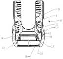
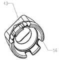
도 1은 척추 고정장치에 제공된 볼 및 소켓 패스너를 도시한 상부 투시도.
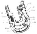
도 2는 구 형태의 볼과 연결 부재 사이에서 다축구성 방식으로 협력하는 것을 예시하고 있는 고정 부재를 가진 볼 및 소켓 패스너를 도시한 상부 투시도.
도 3은 볼 및 소켓 패스너를 도시한 측면도.
도 4는 볼 및 소켓 패스너의 일부분을 도시한 도면.
도 5는 연결 조립체를 도시한 단면도.
도 6은 연결 조립체를 도시한 상부 단면도.
도 7은 도 6의 라인 7-7을 따라 절단한 연결 조립체의 일부분을 도시한 투시도.
도 8은 연결 조립체를 도시한 상부 투시도.
도 9는 연결 조립체를 도시한 상부도.
도 10은 도 9의 라인 10-10을 따라 절단한 연결 조립체를 도시한 단면도.
도 11은 연결 부재의 일부분을 도시한 바닥 투시도.
도 12는 연결 부재의 일부분을 도시한 상부 투시도.
도 13은 연결 부재의 바닥을 도시한 도면.
도 14는 연결 부재의 시트 부분을 도시한 상부 투시도.
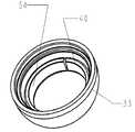
도 15는 하부 스플릿 리테이닝 링을 도시한 투시도.
도 16은 하부 리테이닝 링과 시트 부분을 예시하고 있는 투시도.
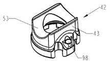
도 17은 상부 리테이닝 링을 도시한 상부 투시도.
도 18은 상부 리테이닝 링을 도시한 하부 투시도.
도 19는 구 형태의 커넥터에 리테이닝 어셈블리가 조립되는 것을 도시한 투시도.
도 20a는 연결 조립체와 구 형태의 볼이 조립된 것을 예시하고 있는 측면도.
도 20b는 연결 조립체와 구 형태의 볼이 조립된 것을 예시하고 있는 측면도.
도 20c는 연결 조립체와 구 형태의 볼이 조립된 것을 예시하고 있는 측면도.
도 20d는 연결 조립체와 구 형태의 볼이 조립된 것을 예시하고 있는 측면도.
도 20e는 연결 조립체와 구 형태의 볼이 조립된 것을 예시하고 있는 측면도.
도 20f는 연결 조립체와 구 형태의 볼이 조립된 것을 예시하고 있는 측면도.
도 20g는 연결 조립체와 구 형태의 볼이 조립된 것을 예시하고 있는 측면도.
도 20h는 연결 조립체와 구 형태의 볼이 조립된 것을 예시하고 있는 측면도.
도 21a는 연결 조립체와 구 형태의 볼이 조립된 것을 예시하고 있는 단면도.
도 21b는 연결 조립체와 구 형태의 볼이 조립된 것을 예시하고 있는 단면도.
도 21c는 연결 조립체와 구 형태의 볼이 조립된 것을 예시하고 있는 단면도.
도 21d는 연결 조립체와 구 형태의 볼이 조립된 것을 예시하고 있는 단면도.
도 21e는 연결 조립체와 구 형태의 볼이 조립된 것을 예시하고 있는 단면도.
도 21f는 연결 조립체와 구 형태의 볼이 조립된 것을 예시하고 있는 단면도.
도 21g는 연결 조립체와 구 형태의 볼이 조립된 것을 예시하고 있는 단면도.
도 21h는 연결 조립체와 구 형태의 볼이 조립된 것을 예시하고 있는 단면도.
도 22는 본 발명의 대안의 구체예를 도시한 투시도.
도 23은 도 22에 예시된 구체예의 일부분을 도시한 측면도.
도 24는 도 22에 예시된 구체예를 도시한 상부도.
도 25는 리테이닝 너트를 도시한 투시도.
도 26은 오직 단일축 운동만을 가진 본 발명의 대안의 구체예를 도시한 투시도.
도 27은 도 26에 예시된 구체예의 골 고정장치를 도시한 전면도.
도 28은 도 26에 도시된 구체예의 골 고정장치를 도시한 측면도.
도 29는 단일축 구체예에서 사용되는 구 형태의 커넥터의 일부분을 도시한 투시도.
도 30은 단일축 구체예에서 사용되는 연결 조립체의 일부분을 도시한 도면.
도 31은 단일축 구체예에서 사용되는 상부 리테이닝 링을 도시한 하부 투시도.1 is an upper perspective view showing a ball and socket fastener provided in a spinal fixation device;
Figure 2 is an upper perspective view of a ball and socket fastener having a fastening member illustrating cooperating in a multi-axial configuration manner between spherical balls and connecting members;
3 is a side view showing a ball and socket fastener;
Figure 4 shows a portion of a ball and socket fastener;
5 is a cross-sectional view of a connection assembly;
6 is a top cross-sectional view of the connection assembly;
7 is a perspective view showing a portion of the connection assembly cut along line 7-7 of Fig. 6; Fig.
8 is an upper perspective view illustrating the connection assembly;
Figure 9 is a top view of the connection assembly.
10 is a cross-sectional view of the connection assembly cut along line 10-10 of FIG. 9;
11 is a bottom perspective view showing a portion of a connecting member;
12 is an upper perspective view showing a portion of the connecting member;
13 is a bottom view of the connecting member.
14 is an upper perspective view showing the seat portion of the connecting member;
15 is a perspective view showing a lower split retaining ring;
16 is a perspective view illustrating a lower retaining ring and a seat portion;
17 is an upper perspective view showing the upper retaining ring;
18 is a bottom perspective view showing the upper retaining ring;
19 is a perspective view showing the retaining assembly being assembled to a spherical connector.
Figure 20a is a side view illustrating assembly of a connection assembly and a spherical ball.
20B is a side view illustrating assembly of a connection assembly and spherical balls.
20C is a side view illustrating assembly of a connection assembly and a spherical ball.
20D is a side view illustrating assembly of a connection assembly and a spherical ball.
20E is a side view illustrating assembly of a connection assembly and a spherical ball.
Figure 20f is a side view illustrating assembly of a connection assembly and a spherical ball.
20g is a side view illustrating assembly of a connection assembly and a spherical ball;
Figure 20h is a side view illustrating assembly of a connection assembly and a spherical ball.
21A is a cross-sectional view illustrating assembly of a connection assembly and a spherical ball.
Figure 21b is a cross-sectional view illustrating the assembly of a connection assembly and a spherical ball.
Figure 21c is a cross-sectional view illustrating the assembly of a connection assembly and a spherical ball.
21D is a cross-sectional view illustrating the assembly of a connection assembly and a spherical ball.
FIG. 21E is a cross-sectional view illustrating assembly of a connection assembly and a spherical ball. FIG.
Figure 21f is a cross-sectional view illustrating the assembly of a connection assembly and a spherical ball.
Figure 21g is a cross-sectional view illustrating the assembly of a connection assembly and a spherical ball.
21h is a cross-sectional view illustrating the assembly of a connection assembly and a spherical ball.
22 is a perspective view showing an alternative embodiment of the present invention;
Figure 23 is a side view showing a portion of the embodiment illustrated in Figure 22;
FIG. 24 is a top view showing an embodiment illustrated in FIG. 22; FIG.
25 is a perspective view showing a retaining nut;
26 is a perspective view illustrating an alternative embodiment of the present invention having only a single axis motion.
Fig. 27 is a front view showing a bone anchoring device of the embodiment illustrated in Fig. 26; Fig.
28 is a side view showing a bone anchoring device of the embodiment shown in Fig. 26;
29 is a perspective view showing a portion of a spherical connector used in a single axial embodiment;
Figure 30 shows a portion of a coupling assembly used in a single axial embodiment.
31 is a bottom perspective view showing an upper retaining ring used in a single axial embodiment;
본 발명의 구체예가 다양한 형태들로 나타날 수 있지만, 도면에서는 하나의 구체예가 도시되어 있고, 본 명세서에서는 바람직한 구체예로 기술될 것이며, 본 명세서가 본 발명의 대표적인 실례로서 간주되어야 하고 본 발명을 도시되어 있는 특정 구체예들에만 제한하기 위함이 아니라는 사실을 이해해야 한다.While embodiments of the present invention may appear in a variety of forms, one embodiment is illustrated in the drawings and described herein as a preferred embodiment, and the description is to be regarded as a representative instance of the invention, It is to be understood that the invention is not intended to be limited to the specific embodiments in which the invention is based.
도면 전반에서 보면, 척추 고정 시스템에서 사용하기 위해 구성된 고정식 다축구성 볼 및 소켓 고정 시스템의 대표적인 구체예가 기술되어 있다.Throughout the figures, representative embodiments of a fixed multi-axis configuration ball and socket fixation system configured for use in a spinal fixation system are described.
상기 볼 및 소켓 고정 시스템은 골 고정장치(bone anchor)와 일체형으로 형성되거나 또는 골 고정장치에 고정된 구 형태의 볼 및 다축구성 조인트(polyaxial joint)를 형성하기 위하여 상기 구 형태의 볼을 위한 스냅-인(snap-in) 타입의 리셉터클(38)을 포함하는 연결 조립체를 포함한다. 이 연결 조립체는 두 개 이상의 골 고정장치들을 함께 고정시키기 위하여 연결 로드 부재와 결합하여 사용될 수 있는 리시버(receiver)를 포함한다.The ball and socket fixation system may include a ball-shaped ball integrally formed with a bone anchor or fixed to a bone anchor and a snap for the spherical ball to form a multi-axial joint. And a
도 1-4와 도 19를 보면, 바람직한 구체예의 골 고정장치는 일정 길이를 가진 섕크(14)를 포함하는 골 나사(12)이며, 하나 이상의 나선형 스레드(16)가 상기 섕크(14)의 길이를 따라 형성된다. 여기서 기술된 골 나사의 비율은 오직 예시적인 목적만을 위해서이며 섕크의 길이, 나사의 직경, 스레드 피치, 스레드 길이, 스레드 리드(lead)의 개수, 섕크 유도 압축률(shank induced compression) 및 이와 유사한 것들은 본 발명의 범위를 벗어나지 않고 변경될 수도 있음을 이해하는 것은 중요하다. 섕크(14)의 상측 단부(20)에서, 미리 정해진 직경(d)을 가진 볼 형태의 구 형태의 커넥터(18)가 있다(도 19 참조). 드라이빙 공구(driving tool)를 사용하여 골 나사를 장착하는데 사용하기 위하여 구 형태의 커넥터의 상측 단부(20)를 따라 드라이버 리셉터클(22)이 위치된다. 상기 드라이버 리셉터클은 골 나사를 회전시켜 최종 위치로 가기 위해 드라이빙 공구와 협력하기에 적합하도록 수(male) 또는 암(female) 형태로, 임의의 형태로 구성될 수 있다는 점을 유의해야 한다.1-4 and 19, the bone anchoring device of the preferred embodiment is a
도 1-16을 보면, U자형 연결 조립체가 도시되어 있다. 이 U자형 연결 조립체(30)는 상부 연결 부재(31)(도 11-13 참조), 하부 연결 부재(33)(도 14 참조), 상부 리테이닝 링(42) 및 하부 스플릿 리테이닝 링(40)(도 5 참조)을 포함한다. 상기 상부 연결 부재는 실질적으로 원형의 측벽(32)을 포함하며, 이 원형 측벽(32)은 직립(upstanding)의 제 1 측벽(34)과 제 2 측벽(36)을 형성하는 한 쌍의 U자형 개구(opening)들에 의해 분리된다. 상기 측벽들은 복수의 오목한 홈(recessed flute)(90)들을 포함하는 것이 바람직하다. 이 홈들은 공구(도시되지 않음)와 협력하여 세트 나사(set screw)(80)를 조이는 동안 의사가 연결 부재에 카운터 토크(counter torque)를 가하게 할 수 있도록 하는 그리핑 표면(gripping surface)을 제공하도록 구성되고 배열된다(도 1). 이 홈들 외에도, 홈(91)이 익스텐더 튜브(extender tube)(도시되지 않음)의 부착을 위해 연결 부재의 주변(perimeter) 주위로 절단된다(cut). 익스텐더 튜브들은 최소 침습 척추 수술(minimally invasive spinal procedure)법에서 잘 알려져 있다. 상부 연결 조립체의 하측 표면은 하부 스플릿 리테이닝 링(40)을 개방하기 위해 조립하는 동안 하부 스플릿 리테이닝 링(40)과 협력하여 이에 따라 구 형태의 볼의 주 직경(d)(도 19 참조)이 상기 스플릿 링을 통과할 수 있도록 위치된 복수의 램프(ramp)(94)들을 포함한다(도 21a-21h 참조).1-16, a U-shaped connection assembly is shown. The U-shaped connecting
도 4-16을 보면, 상부 연결 부재 (31)은 하부 연결 부재(33)의 배치를 위해 바닥 표면 위에 숄더(92)를 포함하는 것이 바람직하다. 또한 하부 연결 부재(33)는 두 구성요소들이 나란하게 정렬된 상태를 유지하기 위해 상기 숄더(92)와 협력하도록 구성되고 배열된 숄더(96)를 포함한다. 하부 연결 부재(33)는 하부 스플릿 리테이닝 링(40)과 상부 리테이닝 링(42)을 수용하는 실질적으로 구 형태의 하부 리셉터클(38)을 포함한다. 리테이닝 링(40, 42)은 제조 공정 동안 하부 리셉터클(38) 내에 배열된다. 숄더(92 및 96)는 이 구성요소들을 나란하게 정렬하도록 사용되고 상부 및 하부 연결 부재들은 조립 후에 리테이닝 링들이 떨어지는(dislodgement) 것을 방지하기 위해 함께 레이저 용접된다(laser welded). 본 발명의 범위를 벗어나지 않고도 상부 및 하부 연결 부재들을 함께 부착하기 위한 그 외의 다른 적절한 방법 또는 수술기술들이 사용될 수 있으며, 이러한 방법들은 스폿 용접(spot welding), 스레드(thread), 접착(adhesive), 핀 스웨이징(pins swaging), 납땜(solder), 억지 끼워맞춤(interference fit) 및 이들의 적절한 조합들을 포함할 수 있으나 이들에만 제한되어서는 안 된다는 사실을 유의해야 한다.4-16, the upper connecting
도 5-13과 17-18을 보면, 상부 리테이닝 링(42)이 도시되어 있다. 상부 리테이닝 링(42)은 하부 리셉터클(38) 내에 위치되는데, 상부 에지(52)가 측벽(41)에 의해 형성된 공동(cavity) 내에 위치될 수 있으며; 상부 리테이닝 링 측벽(43)은 상부 리테이닝 링이 회전하는 것을 방지하기 위해 상기 공동의 측벽(41)과 협력한다. 상부 리테이닝 링의 내측 표면(56)은 구 형태의 커넥터(18)의 외측 표면과 결합되어(engaging) 자체적으로 중앙에 위치하기 위해(self centering) 제공된다. 상부 리테이닝 링(104))의 상측 표면(53)은 연결 로드(70)와 협력하기 위해 오목한 원통형의 표면을 포함하는 것이 바람직하다. 이 원통형의 표면은 연결 로드와 접촉하기 위해 또 다른 표면적을 제공하며 연결 조립체(30)와 로드 사이에 그리핑 파워(gripping power)를 증가시키도록 구성된 깔쭉한(knurled) 또는 그 외의 경우 변경된 표면 마감재(surface finish)를 포함할 수 있다. 상부 리테이닝 링(42)의 한 구체예는 스프링 포켓(98)을 포함하는데, 이 스프링 포켓(98)은 코일 스프링(102)(도 5 참조)을 포함하고 배치하도록 상부 연결 부재 내에 위치된 스프링 포켓(100)(도 11 참조)들과 협력하도록 위치된다. 이 스프링 부재들은 상부 리테이닝 링들이 하부 리셉터클의 개구(50)를 향하도록 편향시킨다(bias).5-13 and 17-18, an
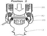
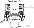
도 19-21h를 보면, 고정식 다축구성 볼 및 소켓 패스너의 조립체가 도시되어 있다. 조립 전에, 골 고정장치(12)는 골에 부착된 연결 부재 없이 정상적인 방식으로 골 내에 삽입될 수 있다. 이에 따라 의사는 나사가 골 내로 회전할 때 나사를 선명하게 볼 수 있다. 골 나사를 삽입한 후에, 골 고정장치(12)의 구 형태의 커넥터(18)가 개구(50)(도 21a 참조)를 통해 삽입되는데, 이 구 형태의 커넥터(18)는 하부 리테이닝 링(40)과 접촉한다. 하부 리테이닝 링은 상부 리테이닝 링(도 21b 참조)과 접촉하도록 밀려져서 스프링(102)을 압축시켜(collapsing) 하부 리테이닝 링이 램프(94)와 접촉하게 한다(도 21c 참조). 하부 리테이닝 링의 상측 표면과 램프가 협력함으로써 하부 리테이닝 링은 볼의 주 직경(d)에 걸쳐 고정되도록(snap) 직경이 개방되게 한다(open up)(도 21d-21f 참조). 하부 리테이닝 링이 충분히 개방되면, 스프링(102)들은 하부 리테이닝 링을 하부 리셉터클의 하측 부분으로 이동시켜 연결 조립체가 나사에 대해 다축 운동(polyaxial movement)을 할 수 있게 하면서도 볼이 하부 리셉터클로부터 빠지지 않게 방지한다(도 21g-21h 참조). 그 뒤, 연결 조립체 내에 연결 로드(70)를 배치시킴으로써 볼 및 소켓 연결부를 원하는 위치에 고정하는 공정이 구현되며, 이에 따라 상부 리테이닝 링의 상측 표면(53)과 접촉한다. 세트 나사(80) 형태의 고정 요소(securing element)가 상기 세트 나사가 로드(70)와 접촉할 때까지 상부 리테이닝 부재의 스레드구성 부분 내로 삽입되며, 로드가 구 형태의 볼(18)과 접촉하도록 상부 리테이닝 링을 이동시키게 한다. 이 운동은 볼이 개구(50)를 향해 이동시키게 하여 볼과 하부 리테이닝 링의 내측 표면(120)(도 14 참조) 사이에 하부 스플릿 리테이닝 링(40)을 끼워넣어(wedging), 이 조립체를 원하는 위치에 고정시킨다. 이러한 구성으로 인해 두 링들이 연결 조립체와 구 형태의 볼 사이에서 접촉하게 되는 것을 이해해야 한다. 제 1 접촉 링은 상부 리테이닝 링(42)에 의해 제공되며 제 2 접촉 링은 하부 리테이닝 링(40)에 의해 제공된다. 코일 스프링으로서 스프링(102)들이 도시되어 있지만, 스플릿 리테이닝 링을 이동시키기(displacing) 위해 적합한 임의의 스프링 또는 탄성(resilient) 타입의 부재가 본 발명의 범위를 벗어나지 않고 사용될 수 있음을 유의해야 한다. 이러한 스프링 또는 탄성 부재들은 Belleville 타입의 스프링, 리프 스프링(leaf spring), 폴리머 부재 및 이들의 적절한 조합들을 포함할 수 있지만 이들에만 제한되어서는 안 된다.19-21h, an assembly of fixed multi-axis construction ball and socket fasteners is shown. Prior to assembly, the
본 발명의 독특한 점은 의사가 다양한 타입의 골 고정장치 또는 이와 유사한 장치를 연결 조립체에 부착시키게 하는 기능이다. 구 형태의 볼, 골 후크장치(bone hook) 등을 포함하도록 구성될 수 있는 무수한 고정 장치들이 있지만, 도시하기 쉽게 골 나사가 도시되어 있으며 다양한 길이와 직경을 가진 골 나사가 사용가능하고 이들의 대다수는 연결 조립체의 내측 직경을 통해 꼭 들어맞지 않을 것이라는 것은 아주 잘 알려진 사실이다. 설치하기에 가장 잘 맞는 스레드 스타일(thread style), 길이 등등이 수술 전에 추정될(estimated) 수 있지만, 실제 수술 동안에는 오직 적합한 스타일만이 확정될 수 있다는 것은 아주 잘 알려져 있다. 고정 나사와 연결 부재의 적절한 조합을 예측하기가 가장 어렵기 때문에, 의사들은 척추 임플란트를 선택할 수 있는 폭이 넓거나 또는 가장 가까운 조합을 사용하게 되고 그것이 충분할 것이라고 희망한다.It is a unique feature of the present invention to allow the physician to attach various types of bone anchoring devices or similar devices to the connection assembly. Although there are a myriad of fastening devices that can be configured to include ball-shaped balls, bone hooks, and the like, bone screws are shown for ease of illustration, bone screws of various lengths and diameters are available, It is well known that the inner diameter of the coupling assembly will not fit through the inner diameter. It is well known that while the thread style, length, etc. best suited for installation can be estimated prior to surgery, only the appropriate styles can be determined during actual surgery. Since it is most difficult to predict the proper combination of fixation screws and connecting members, doctors hope that it will be sufficient to use a broader or nearest combination of spine implants to choose from.
다양한 타입의 골 나사가 언급되었지만, 상기 설치 방법은 구 형태의 커넥터를 가진 고정 장치가 연결 부재가 부착되기 전의 위치로 배치할 수 있게 하는 것을 유의해야 한다. 이는 의사들로 하여금 연결 부재를 배치하기 전에 골 나사를 배치하는 선택권을 제공하여 간단한 설치 공정을 제공하며 고정 나사를 배열시키는 공정은 근육 또는 그 외의 방해요소(interference)들로 인해 어렵다. 연결 부재로 골 나사를 설치하는 공정은 시각적으로 더 우수한 위치배열 뿐만 아니라 이동할 수 있는 범위도 넓어지게 한다. 또한, U자형 연결 부재가 도시되어 있지만, 다양한 타입의 연결 부재들도 구 형태의 커넥터(18)와 조합하여 사용될 수 있으며 이에 따라 의사는 수술 동안 적절한 조합을 선택할 수 있게 하여 환자의 혜택을 위한 성공 가능성을 향상시킬 뿐만 아니라 의사가 수술 중에 겪을 수 있는 다양한 유형의 경우들을 추정할 때 필요한 인벤토리 비용도 낮출 수 있다.Although various types of bone screws have been mentioned, it should be noted that the mounting method allows the fastening device having a spherical connector to be placed in a position before the connecting member is attached. This provides a simple installation process by providing physicians with the option of placing the bone screws prior to placing the connecting members, and the process of aligning the set screws is difficult due to muscle or other interferences. The process of installing bone screws with connecting members not only provides a better visual arrangement but also allows a wider range of movement. Also, while a U-shaped connecting member is shown, various types of connecting members may also be used in combination with the
스플릿 링으로서 오직 하부 리테이닝 링이 도시되어 있지만, 상부 링도 리테이닝 조립체의 상측 및 하측 부분들을 함께 용접할 필요 없이 하부 리셉터클 내로 배치하는 것을 용이하게 하기 위해 스플릿 링으로 사용될 수 있다.Although only the lower retaining ring is shown as a split ring, the upper ring may also be used as a split ring to facilitate positioning the upper and lower portions of the retaining assembly into the lower receptacle without having to weld together.
도 19를 보면, 구 형태의 커넥터(18)의 외측 표면(83)은 향상된 마찰 결합(frictional engagement)을 위해 오목 스타일의 표면을 포함할 수 있다. 구 형태의 커넥터는 오직 연결 조립체의 바닥 개구(50)를 통해 삽입하기 위해서만 크기가 정해지는 것이 바람직하며 상부 리테이닝 링(42)이 제거되었다 할지라도 연결 부재 개구(80)를 통해 끼워지지 않을 것이라는 것을 유의해야 한다. 이러한 삽입은 통상 연결 부재를 통해 골 나사의 섕크를 배치하는 종래 기술과 상이한 점이며, 여기서 커넥터의 바닥을 따르는 개구는 구 형태의 커넥터가 통과하는 것을 방지하기 위해 크기가 정해진다.19, the
도 4와 19를 보면, 패스너 리셉터클(22)은 다양한 형태들로 구성될 수 있는데, 설치 과정 동안 최소로 미끄러질 때(slippage) 최대 양의 토크(torque)를 제공하는 종래의 패스너 또는 섕크를 제공하는 특징이 있다. 하부 리테이닝 링(40)의 내측 표면(54)(도 15-16 참조)은 설치 과정 동안 구 형태의 커넥터(18)와 결합하고 있는 표면의 최소 부분으로 도시된다. 하지만, 일단 구 형태의 커넥터가 배치되고 나면, 하부 스플릿 리테이닝 링(40)의 내측 표면(54) 대부분은 최적의 마찰 결합을 위해 구 형태의 커넥터(18)와 결합될 것이다. 이와 유사하게, 상부 리테이닝 링(42)(도 18 참조)의 내측 표면(56)도 마찰 결합을 위해 구 형태의 커넥터(18)와 결합된다. 상기 내측 표면(54 및 56)들은 구 형태의 커넥터(18)의 오목한 표면(83)과 협력하는 오목한 표면을 포함한다.4 and 19, the
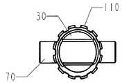
도 22-25을 보면, 본 발명의 대안의 구체예가 도시되어 있다. 이 구체예에서, 세트 나사(80) 대신에 스레드구성 너트(threaded nut)(110)가 사용된다. 상기 스레드구성 너트는 상부 연결 부재(31)의 외측 표면 위에 형성된 외부 스레드(112)들과 협력하도록 구성되고 배열된 내부 나선형 스레드를 포함한다. 상기 스레드구성 너트(110)는 로드 부재(70)와 결합되는 바닥 표면(114)을 포함하며, 이에 따라 상부 리테이닝 부재(42)가 구 형태의 커넥터(18)와 결합하게 하여 하부 연결 부재(33)의 내측 표면(120)과 구 형태의 커넥터 사이에 하부 리테이닝 링(40)이 끼워지고 연결 조립체에 대해 구 형태의 커넥터의 위치를 고정시킨다.22-25, an alternative embodiment of the present invention is shown. In this embodiment, a threaded
도 26-30을 보면, 위에서 기술한 구체예들의 다축 운동(polyaxial movement) 대신에 단일축 운동(mono-axial movement)을 가진 본 발명의 대안의 구체예가 도시되어 있다(도 26 참조). 척추 측만증(scoliosis)과 같은 특정 타입의 척추 질환(하지만 이 질환에만 제한되지 않음)을 위해, 예를 들어 몇몇의 서로 다른 축들을 따르는 다축 운동 대신에, 가령, 예를 들어 단일 축을 따라 단일축 운동을 제공하는 골 고정장치들이 종종 요구된다. 볼 및 소켓 패스너의 운동을 단일 축으로 제한하기 위하여, 구 형태의 커넥터(18)는 구 형태의 커넥터(18)의 서로 맞은편에 있는 측면들 위에 위치된 하나 이상의 유도 표면(guide surface)(116), 보다 바람직하게는, 한 쌍의 유도 표면(116)을 포함한다(도 27 참조). 이 유도 표면(116)은 상부 리테이닝 링(42)의 내측 표면(56) 내에 위치된 레일(rail)(118)들과 협력한다. 이 레일(118)들과 유도 표면(116)들은 골 고정장치(12)가 단일 축을 따라 운동할 수 있게 하면서도 구 형태의 커넥터(18)가 실질적으로 회전하는 것을 방지하기 위해 협력한다(도 26 참조).26-30, there is shown an alternative embodiment of the present invention having a mono-axial movement instead of the polyaxial movement of the embodiments described above (see FIG. 26). (But not limited to) a particular type of spinal disease, such as scoliosis, for example, instead of multi-axis motion along several different axes, for example, single axis motion along a single axis Are often required. In order to limit the movement of the ball and socket fasteners to a single axis, the spherical shaped
본 명세서에서 언급된 모든 특허와 공보들은 본 발명에 관한 당업자의 수준을 나타내고 있다. 이 모든 특허와 공보들은 마치 각각의 공보가 참조문헌으로서 통합될 수 있도록 특징적으로 그리고 개별적으로 나타내고 있는 것과 같은 정도로 본 명세서에서 참조문헌으로 통합된다.All patents and publications mentioned in this specification are indicative of the level of ordinary skill in the art to which this invention pertains. All of these patents and publications are incorporated herein by reference to the same extent as if each of the publications was specifically and individually indicated to be incorporated by reference.
본 발명의 특정 형태가 도시되어 있지만, 본 명세서에서 기술되고 도시되어 있는 특정 형태 또는 배열에만 제한되지 않는다는 것을 이해해야 한다. 당업자들에게는, 본 발명의 범위를 벗어나지 않고 다양한 변경예들이 가능할 수 있으며 본 발명이 본 명세서와 본 명세서에 포함된 도면/형상들에서 기술되고 도시되어 있는 것에만 제한되는 것으로 간주되지 않는다는 것이 자명할 것이다.While particular forms of the invention are shown, it should be understood that they are not limited to the specific forms or arrangements described and illustrated herein. It will be apparent to those skilled in the art that various modifications may be made and that the invention is not deemed to be limited to only those described and shown in the drawings and figures contained herein will be.
당업자는 본 발명이 본 발명의 고유한 목표와 이점들 뿐만 아니라 위에서 언급한 목표와 이점들을 구현하고 본 발명의 목적을 수행하기에 매우 적합하다는 것을 쉽게 이해할 것이다. 본 명세서에서 기술된 구체예, 방법, 절차 및 기술들은 바람직한 구체예들을 나타내고 있으며 대표적인 것일 뿐 본 발명의 범위를 제한하려는 것이 아니다. 본 발명의 사상 내에 포함되며 첨부된 청구항들의 범위에 의해 정의된 것과 같이 본 명세서에서 사용된 변경예들과 그 외의 다른 사용법들도 당업자에게 자명할 것이다. 본 발명이 특정의 바람직한 구체예들에 대해 기술되었지만, 본 발명은 청구된 것과 같이 오직 이러한 특정 구체예들에만 제한되어서는 안 된다는 것을 이해해야 한다. 실제로, 당업자에게 자명한 본 발명을 수행하기 위해 위에서 언급한 다양한 형태의 변형예들은 하기 청구항들의 범위 내에 있다.Those skilled in the art will readily appreciate that the present invention is well suited to the implementation of the objects and advantages of the present invention as well as the objects and advantages mentioned above. The embodiments, methods, procedures, and techniques described herein are representative of preferred embodiments and are not intended to limit the scope of the invention. Modifications and other uses as used herein, as defined by the scope of the appended claims and included within the scope of the present invention, will be apparent to those skilled in the art. While the invention has been described with respect to certain preferred embodiments, it is to be understood that the invention is not to be limited to only those specific embodiments, as claimed. Indeed, various modifications of the above-described form for carrying out the invention that are apparent to those skilled in the art are within the scope of the following claims.
Claims (21)
Translated fromKorean- 구 형태의 커넥터와 섕크를 가진 고정 부재를 포함하며;
- 소켓, 상부 리테이닝 링 및 하부 리테이닝 링을 가진 연결 조립체를 포함하고, 상기 소켓은 제 2 단부에 고정할 수 있는 고정 요소(securing element)와 제 1 단부를 따라 상기 구 형태의 커넥터를 수용하기 위하여 구성되고 배열되며, 상기 상부 리테이닝 링은 상기 구 형태의 커넥터의 상측 표면을 따라 위치될 수 있고 상기 소켓 내에 배열되며, 상기 하부 리테이닝 링은 상기 구 형태의 커넥터의 하측 표면을 따라 위치될 수 있고 상기 소켓 내에 배열되어 상기 연결 조립체가 상기 고정 부재에 대해 다축 운동을 수행하며(move polyaxially), 상기 고정 요소는 상기 다축 운동을 조절하기 위해 고정 위치(locked position)와 풀린 위치(unlocked position) 사이에서 횡단할 수 있고(traversable);
- 연결 조립체의 하측 표면을 포함하며, 상기 연결 조립체의 하측 표면은, 상기 하부 리테이닝 링을 개방하기 위하여 상기 구 형태의 커넥터를 소켓에 고정하는 동안, 상기 구 형태의 커넥터의 주 직경(main diameter)이 하부 리테이닝 링을 통과할 수 있도록, 상기 하부 리테이닝 링의 상측 표면과 협력하도록(cooperate) 위치된 복수의 램프 표면(ramp surface)을 포함하며,
상기 구 형태의 커넥터의 헤드(head)가 상기 상부 및 하부 리테이닝 링 사이에 위치되고 상기 제 1 단부를 통해 수용되는 것을 특징으로 하는 볼 및 소켓 패스너.A ball and socket fastener comprising: a ball and socket fastener comprising:
A fixing member having a spherical connector and a shank;
A connection assembly having a socket, an upper retaining ring and a lower retaining ring, the socket having a securing element for securing to the second end and a socket for receiving the spherical connector along the first end, Wherein the upper retaining ring is positionable along the upper surface of the spherical connector and is arranged in the socket and the lower retaining ring is positioned and positioned along the lower surface of the spherical connector, And is arranged in the socket such that the connecting assembly moves polyaxially with respect to the fastening member and the fastening element is movable between a locked position and an unlocked position to adjust the multi- ); ≪ / RTI >
Wherein the lower surface of the connecting assembly includes a lower surface of the connecting assembly having a main diameter of the spherical connector during main securing of the spherical connector to the socket to open the lower retaining ring, ) Includes a plurality of ramp surfaces positioned cooperatively with an upper surface of the lower retaining ring so as to be able to pass through the lower retaining ring,
Wherein a head of said spherical connector is located between said upper and lower retaining rings and is received through said first end.
- 구 형태의 커넥터와 섕크를 가진 고정 부재를 포함하며, 상기 구 형태의 커넥터는 하나 이상의 유도 표면(guide surface)을 포함하고;
- 소켓, 상부 리테이닝 링 및 하부 리테이닝 링을 가진 연결 조립체를 포함하고, 상기 소켓은 제 2 단부에 고정할 수 있는 고정 요소와 제 1 단부를 따라 상기 구 형태의 커넥터를 수용하기 위하여 구성되고 배열되며, 상기 상부 리테이닝 링은 상기 구 형태의 커넥터의 상측 표면을 따라 위치될 수 있고 상기 소켓 내에 배열되며, 상기 상부 리테이닝 링은 상기 하나 이상의 유도 표면과 협력하도록 위치된 하나 이상의 레일(rail)을 포함하고, 상기 하부 리테이닝 링은 상기 구 형태의 커넥터의 하측 표면을 따라 위치될 수 있고 상기 소켓 내에 배열되며, 상기 하나 이상의 유도 표면과 상기 하나 이상의 레일은 상기 연결 조립체가 상기 고정 부재에 대해 단일축 운동을 수행하도록(move mono-axially) 협력하고, 상기 고정 요소는 상기 단일축 운동을 조절하기 위해 고정 위치와 풀린 위치 사이에서 횡단할 수 있고;
- 연결 조립체의 하측 표면을 포함하며, 상기 연결 조립체의 하측 표면은, 상기 하부 리테이닝 링을 개방하기 위하여 상기 구 형태의 커넥터를 소켓에 고정하는 동안, 상기 구 형태의 커넥터의 주 직경이 하부 리테이닝 링을 통과할 수 있도록, 상기 하부 리테이닝 링의 상측 표면과 협력하도록 위치된 복수의 램프 표면을 포함하며,
상기 구 형태의 커넥터의 헤드가 상기 상부 및 하부 리테이닝 링 사이에 위치되고 상기 제 1 단부를 통해 수용되는 것을 특징으로 하는 볼 및 소켓 패스너.A ball and socket fastener comprising: a ball and socket fastener comprising:
A fixing member having a spherical connector and a shank, the spherical connector comprising one or more guide surfaces;
- a connection assembly having a socket, an upper retaining ring and a lower retaining ring, the socket being configured for receiving the spherical connector along a first end and a securing element for securing to a second end Wherein the upper retaining ring is located along the upper surface of the spherical connector and is arranged in the socket and the upper retaining ring comprises one or more rails Wherein the lower retaining ring is positionable along a lower surface of the spherical connector and is arranged in the socket, the at least one guide surface and the at least one rail are configured such that the connection assembly (Mono-axially), and wherein the stationary element is adapted to move the single- Can be traversed between a fixed position and a released position;
Wherein the lower surface of the connection assembly includes a lower surface of the connection assembly that is configured such that while the spherical connector is secured to the socket to open the lower retaining ring, A plurality of ramp surfaces positioned to cooperate with an upper surface of the lower retaining ring to allow passage of the inning ring,
And a head of said spherical connector is positioned between said upper and lower retaining rings and received through said first end.
- 상기 다축구성 볼 및 소켓 조인트는 척추에 고정하도록 사용하기 위해 한 단부 위에서는 스레드들을 가지고 다른 단부 위에서는 연결 조립체가 다축 운동을 수행할 수 있는 피벗 포인트(pivot point)로서 작용하는 구 형태의 커넥터를 가진 골 나사(bone screw)를 포함하며, 상기 연결 조립체는 U자 형태를 가지고 상부 리테이닝 링 및 하부 스플릿 리테이닝 링을 수용하기 위한 소켓으로서 작용하는 하부 리셉터클을 포함하며,
- 연결 조립체의 하측 표면을 포함하며, 상기 연결 조립체의 하측 표면은, 하부 리테이닝 링을 개방하기 위하여 상기 구 형태의 커넥터를 소켓에 고정하는 동안, 상기 구 형태의 커넥터의 주 직경이 하부 리테이닝 링을 통과할 수 있도록, 상기 하부 리테이닝 링의 상측 표면과 협력하도록 위치된 복수의 램프 표면을 포함하며,
상기 소켓은 하부 스플릿 리테이닝 링을 통해 삽입되는 구 형태의 커넥터에 수용되며, 상기 소켓을 일시적으로 이동하게 하여 상기 구 형태의 커넥터가 상기 상부 리테이닝 링과 하부 리테이닝 링 사이에 위치될 수 있게 하는 것을 특징으로 하는 다축구성 볼 및 소켓 조인트.A multiaxial construction ball and socket joint which can be secured in a fixed position, said multiaxial construction ball and socket joint comprising:
Said multiaxial construction ball and socket joint comprises a sphere-shaped connector which acts as a pivot point for threading on one end and for performing multiaxial motion on the other end for use to secure to the vertebrae; Wherein the connecting assembly includes a lower receptacle having a U-shape and serving as a socket for receiving an upper retaining ring and a lower split retaining ring,
Wherein the lower surface of the connecting assembly includes a lower retaining ring for retaining the spherical connector in the socket while securing the spherical connector in the socket to open the lower retaining ring, A plurality of ramp surfaces positioned to cooperate with an upper surface of the lower retaining ring to allow passage therethrough,
The receptacle is received in a spherical connector inserted through a lower split retaining ring to temporarily move the socket so that the spherical connector can be positioned between the upper retaining ring and the lower retaining ring Wherein the multi-axis configuration ball and socket joint comprises:
Applications Claiming Priority (3)
| Application Number | Priority Date | Filing Date | Title |
|---|---|---|---|
| US11451508P | 2008-11-14 | 2008-11-14 | |
| US61/114,515 | 2008-11-14 | ||
| PCT/US2009/064187WO2010056846A2 (en) | 2008-11-14 | 2009-11-12 | Locking polyaxial ball and socket fastener |
Publications (2)
| Publication Number | Publication Date |
|---|---|
| KR20110099247A KR20110099247A (en) | 2011-09-07 |
| KR101688241B1true KR101688241B1 (en) | 2017-01-02 |
Family
ID=42170691
Family Applications (1)
| Application Number | Title | Priority Date | Filing Date |
|---|---|---|---|
| KR1020117013596AExpired - Fee RelatedKR101688241B1 (en) | 2008-11-14 | 2009-11-12 | Locking polyaxial ball and socket fastener |
Country Status (6)
| Country | Link |
|---|---|
| US (2) | US7947065B2 (en) |
| EP (1) | EP2361044A4 (en) |
| JP (1) | JP5677701B2 (en) |
| KR (1) | KR101688241B1 (en) |
| AU (1) | AU2009314046B2 (en) |
| WO (1) | WO2010056846A2 (en) |
Families Citing this family (164)
| Publication number | Priority date | Publication date | Assignee | Title |
|---|---|---|---|---|
| US7833250B2 (en) | 2004-11-10 | 2010-11-16 | Jackson Roger P | Polyaxial bone screw with helically wound capture connection |
| US8377100B2 (en) | 2000-12-08 | 2013-02-19 | Roger P. Jackson | Closure for open-headed medical implant |
| US8353932B2 (en) | 2005-09-30 | 2013-01-15 | Jackson Roger P | Polyaxial bone anchor assembly with one-piece closure, pressure insert and plastic elongate member |
| US7862587B2 (en) | 2004-02-27 | 2011-01-04 | Jackson Roger P | Dynamic stabilization assemblies, tool set and method |
| US7879075B2 (en) | 2002-02-13 | 2011-02-01 | Zimmer Spine, Inc. | Methods for connecting a longitudinal member to a bone portion |
| US11224464B2 (en) | 2002-05-09 | 2022-01-18 | Roger P. Jackson | Threaded closure with inwardly-facing tool engaging concave radiused structures and axial through-aperture |
| US8876868B2 (en) | 2002-09-06 | 2014-11-04 | Roger P. Jackson | Helical guide and advancement flange with radially loaded lip |
| US8172885B2 (en)* | 2003-02-05 | 2012-05-08 | Pioneer Surgical Technology, Inc. | Bone plate system |
| US6716214B1 (en) | 2003-06-18 | 2004-04-06 | Roger P. Jackson | Polyaxial bone screw with spline capture connection |
| US7621918B2 (en) | 2004-11-23 | 2009-11-24 | Jackson Roger P | Spinal fixation tool set and method |
| US7377923B2 (en) | 2003-05-22 | 2008-05-27 | Alphatec Spine, Inc. | Variable angle spinal screw assembly |
| US8366753B2 (en) | 2003-06-18 | 2013-02-05 | Jackson Roger P | Polyaxial bone screw assembly with fixed retaining structure |
| US7776067B2 (en) | 2005-05-27 | 2010-08-17 | Jackson Roger P | Polyaxial bone screw with shank articulation pressure insert and method |
| US7766915B2 (en) | 2004-02-27 | 2010-08-03 | Jackson Roger P | Dynamic fixation assemblies with inner core and outer coil-like member |
| US8926670B2 (en) | 2003-06-18 | 2015-01-06 | Roger P. Jackson | Polyaxial bone screw assembly |
| US11419642B2 (en) | 2003-12-16 | 2022-08-23 | Medos International Sarl | Percutaneous access devices and bone anchor assemblies |
| US7527638B2 (en) | 2003-12-16 | 2009-05-05 | Depuy Spine, Inc. | Methods and devices for minimally invasive spinal fixation element placement |
| US7179261B2 (en) | 2003-12-16 | 2007-02-20 | Depuy Spine, Inc. | Percutaneous access devices and bone anchor assemblies |
| US7160300B2 (en) | 2004-02-27 | 2007-01-09 | Jackson Roger P | Orthopedic implant rod reduction tool set and method |
| JP2007525274A (en) | 2004-02-27 | 2007-09-06 | ロジャー・ピー・ジャクソン | Orthopedic implant rod reduction instrument set and method |
| US11241261B2 (en) | 2005-09-30 | 2022-02-08 | Roger P Jackson | Apparatus and method for soft spinal stabilization using a tensionable cord and releasable end structure |
| US8152810B2 (en) | 2004-11-23 | 2012-04-10 | Jackson Roger P | Spinal fixation tool set and method |
| US8926672B2 (en) | 2004-11-10 | 2015-01-06 | Roger P. Jackson | Splay control closure for open bone anchor |
| US7875065B2 (en) | 2004-11-23 | 2011-01-25 | Jackson Roger P | Polyaxial bone screw with multi-part shank retainer and pressure insert |
| US9168069B2 (en) | 2009-06-15 | 2015-10-27 | Roger P. Jackson | Polyaxial bone anchor with pop-on shank and winged insert with lower skirt for engaging a friction fit retainer |
| US8308782B2 (en)* | 2004-11-23 | 2012-11-13 | Jackson Roger P | Bone anchors with longitudinal connecting member engaging inserts and closures for fixation and optional angulation |
| WO2006057837A1 (en) | 2004-11-23 | 2006-06-01 | Jackson Roger P | Spinal fixation tool attachment structure |
| US9980753B2 (en) | 2009-06-15 | 2018-05-29 | Roger P Jackson | pivotal anchor with snap-in-place insert having rotation blocking extensions |
| US8444681B2 (en) | 2009-06-15 | 2013-05-21 | Roger P. Jackson | Polyaxial bone anchor with pop-on shank, friction fit retainer and winged insert |
| US7901437B2 (en) | 2007-01-26 | 2011-03-08 | Jackson Roger P | Dynamic stabilization member with molded connection |
| CA2670988C (en) | 2006-12-08 | 2014-03-25 | Roger P. Jackson | Tool system for dynamic spinal implants |
| WO2008082836A1 (en)* | 2006-12-29 | 2008-07-10 | Abbott Spine Inc. | Spinal stabilization systems and methods |
| US8636783B2 (en)* | 2006-12-29 | 2014-01-28 | Zimmer Spine, Inc. | Spinal stabilization systems and methods |
| US10792074B2 (en) | 2007-01-22 | 2020-10-06 | Roger P. Jackson | Pivotal bone anchor assemly with twist-in-place friction fit insert |
| US8979904B2 (en) | 2007-05-01 | 2015-03-17 | Roger P Jackson | Connecting member with tensioned cord, low profile rigid sleeve and spacer with torsion control |
| US7947065B2 (en) | 2008-11-14 | 2011-05-24 | Ortho Innovations, Llc | Locking polyaxial ball and socket fastener |
| US8361126B2 (en) | 2007-07-03 | 2013-01-29 | Pioneer Surgical Technology, Inc. | Bone plate system |
| US8623019B2 (en) | 2007-07-03 | 2014-01-07 | Pioneer Surgical Technology, Inc. | Bone plate system |
| EP2211742A4 (en) | 2007-10-24 | 2012-12-19 | Nuvasive Inc | Surgical fixation system and related methods |
| US8007522B2 (en) | 2008-02-04 | 2011-08-30 | Depuy Spine, Inc. | Methods for correction of spinal deformities |
| US9060813B1 (en) | 2008-02-29 | 2015-06-23 | Nuvasive, Inc. | Surgical fixation system and related methods |
| US8197512B1 (en)* | 2008-07-16 | 2012-06-12 | Zimmer Spine, Inc. | System and method for spine stabilization using resilient inserts |
| AU2010260521C1 (en) | 2008-08-01 | 2013-08-01 | Roger P. Jackson | Longitudinal connecting member with sleeved tensioned cords |
| US8075603B2 (en)* | 2008-11-14 | 2011-12-13 | Ortho Innovations, Llc | Locking polyaxial ball and socket fastener |
| US8636778B2 (en)* | 2009-02-11 | 2014-01-28 | Pioneer Surgical Technology, Inc. | Wide angulation coupling members for bone fixation system |
| US11464549B2 (en) | 2009-06-15 | 2022-10-11 | Roger P. Jackson | Pivotal bone anchor assembly with horizontal tool engagement grooves and insert with upright arms having flared outer portions |
| US8998959B2 (en) | 2009-06-15 | 2015-04-07 | Roger P Jackson | Polyaxial bone anchors with pop-on shank, fully constrained friction fit retainer and lock and release insert |
| CN103826560A (en) | 2009-06-15 | 2014-05-28 | 罗杰.P.杰克逊 | Polyaxial Bone Anchor with Socket Stem and Winged Inserts with Friction Fit Compression Collars |
| US11229457B2 (en) | 2009-06-15 | 2022-01-25 | Roger P. Jackson | Pivotal bone anchor assembly with insert tool deployment |
| US9668771B2 (en) | 2009-06-15 | 2017-06-06 | Roger P Jackson | Soft stabilization assemblies with off-set connector |
| EP2485654B1 (en) | 2009-10-05 | 2021-05-05 | Jackson P. Roger | Polyaxial bone anchor with non-pivotable retainer and pop-on shank, some with friction fit |
| US8986349B1 (en) | 2009-11-11 | 2015-03-24 | Nuvasive, Inc. | Systems and methods for correcting spinal deformities |
| US12383311B2 (en) | 2010-05-14 | 2025-08-12 | Roger P. Jackson | Pivotal bone anchor assembly and method for use thereof |
| US10603083B1 (en) | 2010-07-09 | 2020-03-31 | Theken Spine, Llc | Apparatus and method for limiting a range of angular positions of a screw |
| US9084634B1 (en)* | 2010-07-09 | 2015-07-21 | Theken Spine, Llc | Uniplanar screw |
| US8882817B2 (en)* | 2010-08-20 | 2014-11-11 | K2M, Inc. | Spinal fixation system |
| US9393049B2 (en) | 2010-08-20 | 2016-07-19 | K2M, Inc. | Spinal fixation system |
| WO2012030712A1 (en)* | 2010-08-30 | 2012-03-08 | Zimmer Spine, Inc. | Polyaxial pedicle screw |
| US8784027B2 (en) | 2010-09-14 | 2014-07-22 | Enduralock, Llc | Ratchet locking mechanism for threaded fastener |
| US9657766B2 (en) | 2010-09-14 | 2017-05-23 | Enduralock, Llc | Tools and ratchet locking mechanisms for threaded fasteners |
| US20120083845A1 (en)* | 2010-10-05 | 2012-04-05 | Spartek Medical, Inc. | Compound spinal rod and method for dynamic stabilization of the spine |
| EP2637584A4 (en)* | 2010-10-15 | 2015-01-28 | Alphatec Holdings Inc | FIXING SCREW ASSEMBLY |
| AU2011324058A1 (en) | 2010-11-02 | 2013-06-20 | Roger P. Jackson | Polyaxial bone anchor with pop-on shank and pivotable retainer |
| EP2460484A1 (en)* | 2010-12-01 | 2012-06-06 | FACET-LINK Inc. | Variable angle bone screw fixation assembly |
| US8579949B2 (en)* | 2011-01-28 | 2013-11-12 | Warsaw Orthopedic, Inc. | Provisional fixation for a multi-axial screw assembly |
| US20140018867A1 (en)* | 2011-02-04 | 2014-01-16 | Stefan Freudiger | Precaution against jamming on open bone screws |
| US9504495B2 (en) | 2011-02-11 | 2016-11-29 | Blackstone Medical, Inc. | Multi-axial pedicle fixation assembly and method for use |
| US9387013B1 (en) | 2011-03-01 | 2016-07-12 | Nuvasive, Inc. | Posterior cervical fixation system |
| US8337530B2 (en)* | 2011-03-09 | 2012-12-25 | Zimmer Spine, Inc. | Polyaxial pedicle screw with increased angulation |
| JP5865479B2 (en) | 2011-03-24 | 2016-02-17 | ロジャー・ピー・ジャクソン | Multiaxial bone anchor with compound joint and pop-mounted shank |
| US9993269B2 (en) | 2011-07-15 | 2018-06-12 | Globus Medical, Inc. | Orthopedic fixation devices and methods of installation thereof |
| US8888827B2 (en)* | 2011-07-15 | 2014-11-18 | Globus Medical, Inc. | Orthopedic fixation devices and methods of installation thereof |
| US8906068B1 (en) | 2011-09-13 | 2014-12-09 | Bernard M. Bedor | Spinal fixation system and method |
| US9093053B2 (en) | 2011-11-03 | 2015-07-28 | Kenneth Alvin Jungeberg | Arrestor for user operated devices |
| US9157471B2 (en) | 2011-09-26 | 2015-10-13 | Kenneth Alvin Jungeberg | Friction locking spherical joint |
| US10012261B2 (en) | 2011-09-26 | 2018-07-03 | Kenneth Alvin Jungeberg | Method and apparatus for releasably immobilizing an attachment to an external object |
| EP2574297B1 (en)* | 2011-09-30 | 2015-11-11 | Biedermann Technologies GmbH & Co. KG | Bone anchoring device and tool cooperating with such a bone anchoring device |
| US9060814B2 (en) | 2011-10-28 | 2015-06-23 | Ortho Innovations, Llc | Spring clip bottom loading polyaxial ball and socket fastener |
| US8911479B2 (en) | 2012-01-10 | 2014-12-16 | Roger P. Jackson | Multi-start closures for open implants |
| US20130211458A1 (en)* | 2012-02-13 | 2013-08-15 | Warsaw Orthopedic, Inc. | Bone fastener and methods of use |
| US9427260B2 (en)* | 2012-03-01 | 2016-08-30 | Globus Medical, Inc. | Closed-head polyaxial and monaxial screws |
| EP2674123B1 (en) | 2012-06-11 | 2018-03-21 | Biedermann Technologies GmbH & Co. KG | Polyaxial bone anchoring device |
| US10327818B2 (en) | 2012-06-18 | 2019-06-25 | Bruce Francis Hodgson | Method and apparatus for the treatment of scoliosis |
| EP2687171B1 (en) | 2012-07-18 | 2015-04-22 | Biedermann Technologies GmbH & Co. KG | Polyaxial bone anchoring device |
| US9295488B2 (en) | 2012-08-09 | 2016-03-29 | Wilson T. Asfora | Joint fusion |
| US20140074169A1 (en)* | 2012-09-13 | 2014-03-13 | Warsaw Orthopedic, Inc. | Spinal correction system and method |
| US9782204B2 (en) | 2012-09-28 | 2017-10-10 | Medos International Sarl | Bone anchor assemblies |
| US8911478B2 (en) | 2012-11-21 | 2014-12-16 | Roger P. Jackson | Splay control closure for open bone anchor |
| US10058354B2 (en) | 2013-01-28 | 2018-08-28 | Roger P. Jackson | Pivotal bone anchor assembly with frictional shank head seating surfaces |
| US9486249B2 (en)* | 2013-02-14 | 2016-11-08 | Blackstone Medical, Inc. | Rod attachment assembly for occipital plate |
| US8852239B2 (en) | 2013-02-15 | 2014-10-07 | Roger P Jackson | Sagittal angle screw with integral shank and receiver |
| US9005205B2 (en) | 2013-03-04 | 2015-04-14 | Degen Medical, Inc. | Rod insertion tools, rods and methods |
| US9259247B2 (en) | 2013-03-14 | 2016-02-16 | Medos International Sarl | Locking compression members for use with bone anchor assemblies and methods |
| US10342582B2 (en) | 2013-03-14 | 2019-07-09 | DePuy Synthes Products, Inc. | Bone anchor assemblies and methods with improved locking |
| US9724145B2 (en) | 2013-03-14 | 2017-08-08 | Medos International Sarl | Bone anchor assemblies with multiple component bottom loading bone anchors |
| US9775660B2 (en) | 2013-03-14 | 2017-10-03 | DePuy Synthes Products, Inc. | Bottom-loading bone anchor assemblies and methods |
| US20140277153A1 (en) | 2013-03-14 | 2014-09-18 | DePuy Synthes Products, LLC | Bone Anchor Assemblies and Methods With Improved Locking |
| US9655659B2 (en) | 2013-04-20 | 2017-05-23 | Degen Medical, Inc. | Anchor tower |
| US9453526B2 (en) | 2013-04-30 | 2016-09-27 | Degen Medical, Inc. | Bottom-loading anchor assembly |
| FR3005258B1 (en) | 2013-05-02 | 2016-08-05 | Spinevision | POLYAXIAL BONE ANCHOR SYSTEM WITH LOADING THROUGH THE BOTTOM |
| EP3021771A1 (en) | 2013-07-18 | 2016-05-25 | Ortho Innovations, LLC | Spring clip bottom loading polyaxial ball and socket fastener |
| WO2015023815A1 (en)* | 2013-08-15 | 2015-02-19 | Enduralock, Llc | Tools and ratchet locking mechanisms for threaded fasteners |
| US9566092B2 (en) | 2013-10-29 | 2017-02-14 | Roger P. Jackson | Cervical bone anchor with collet retainer and outer locking sleeve |
| US9717533B2 (en) | 2013-12-12 | 2017-08-01 | Roger P. Jackson | Bone anchor closure pivot-splay control flange form guide and advancement structure |
| US9451993B2 (en) | 2014-01-09 | 2016-09-27 | Roger P. Jackson | Bi-radial pop-on cervical bone anchor |
| ES2611014T3 (en)* | 2014-01-13 | 2017-05-04 | Biedermann Technologies Gmbh & Co. Kg | Coupling assembly for coupling a rod to a bone anchoring element, and polyaxial bone anchoring device |
| ES2602982T3 (en) | 2014-01-13 | 2017-02-23 | Biedermann Technologies Gmbh & Co. Kg | Coupling set for coupling a rod with a bone anchoring element, and polyaxial bone anchoring device |
| US9549765B2 (en) | 2014-04-03 | 2017-01-24 | Zimmer Spine, Inc. | Uniplanar bone screw |
| EP2932929B1 (en)* | 2014-04-15 | 2017-02-08 | Biedermann Technologies GmbH & Co. KG | A screw element for use in spinal, orthopedic or trauma surgery and a system of such a screw element and a screw driver adapted thereto |
| US9597119B2 (en) | 2014-06-04 | 2017-03-21 | Roger P. Jackson | Polyaxial bone anchor with polymer sleeve |
| US10064658B2 (en) | 2014-06-04 | 2018-09-04 | Roger P. Jackson | Polyaxial bone anchor with insert guides |
| US10543021B2 (en) | 2014-10-21 | 2020-01-28 | Roger P. Jackson | Pivotal bone anchor assembly having an open ring positioner for a retainer |
| US11219471B2 (en) | 2014-10-21 | 2022-01-11 | Roger P. Jackson | Pivotal bone anchor receiver having an insert with post-placement tool deployment |
| US9924975B2 (en) | 2014-10-21 | 2018-03-27 | Roger P. Jackson | Bone anchor having a snap-fit assembly |
| US10119562B2 (en) | 2014-12-16 | 2018-11-06 | Itt Manufacturing Enterprises Llc | One-hand operable end fitting connector assembly |
| US10149702B2 (en) | 2015-01-12 | 2018-12-11 | Imds Llc | Polyaxial screw and rod system |
| EP3283778B1 (en) | 2015-04-17 | 2020-01-15 | Enduralock, LLC | Locking fastener with deflectable lock |
| US10215217B2 (en) | 2015-04-17 | 2019-02-26 | Enduralock, Llc | Locking fastener with deflectable lock |
| US10801540B2 (en) | 2015-04-17 | 2020-10-13 | Enduralock, Llc | Locking mechanisms with deflectable lock member |
| US9707013B2 (en)* | 2015-04-30 | 2017-07-18 | Warsaw Orthopedic, Inc. | Spinal implant system and methods of use |
| CN104783885A (en)* | 2015-05-06 | 2015-07-22 | 山东威高骨科材料股份有限公司 | Lower screw assembly type universal screw |
| CA3033078A1 (en) | 2015-09-08 | 2017-03-16 | Enduralock, Llc | Locking mechanisms with deflectable washer members |
| US10034691B1 (en) | 2015-12-03 | 2018-07-31 | Nuvasive, Inc. | Bone anchor |
| US9603632B1 (en) | 2016-05-20 | 2017-03-28 | Amendia, Inc. | Tulip bone screw assembly |
| EP3278750B1 (en) | 2016-08-04 | 2018-12-12 | Biedermann Technologies GmbH & Co. KG | Polyaxial bone anchoring device and system of an instrument and a polyaxial bone anchoring device |
| EP3287089B1 (en) | 2016-08-24 | 2019-07-24 | Biedermann Technologies GmbH & Co. KG | Polyaxial bone anchoring device and system of an instrument and a polyaxial bone anchoring device |
| US10485594B2 (en) | 2016-10-04 | 2019-11-26 | Amendia, Inc. | Modular tulip assembly |
| US11154331B2 (en) | 2016-10-04 | 2021-10-26 | Spinal Elements, Inc. | Modular tulip assembly |
| US20180263666A1 (en)* | 2017-03-15 | 2018-09-20 | Christopher John Marden CAIN | Mono to poly axial universal pedicle screw and method of using the same |
| WO2018204676A1 (en)* | 2017-05-03 | 2018-11-08 | Advance Research System, Llc | Extension ready spinal support systems |
| US11648037B2 (en) | 2017-05-03 | 2023-05-16 | Advance Research System, Llc | Extension-ready spinal support system with vascular-safe pedicle screw |
| US10610265B1 (en) | 2017-07-31 | 2020-04-07 | K2M, Inc. | Polyaxial bone screw with increased angulation |
| US10507043B1 (en) | 2017-10-11 | 2019-12-17 | Seaspine Orthopedics Corporation | Collet for a polyaxial screw assembly |
| EP3476340B1 (en) | 2017-10-25 | 2021-06-02 | Biedermann Technologies GmbH & Co. KG | Polyaxial bone anchoring device |
| US10258385B1 (en) | 2017-12-12 | 2019-04-16 | Spinal Llc | Bottom loading polyaxial ball and socket fastener with blocking ring with notched split ring |
| US20190175224A1 (en) | 2017-12-12 | 2019-06-13 | Spinal Llc | Spring clip bottom loading polyaxial ball and socket fastener |
| EP3536271B1 (en) | 2018-03-06 | 2022-05-04 | Biedermann Technologies GmbH & Co. KG | Polyaxial bone anchoring device and system of an instrument and a polyaxial bone anchoring device |
| US11596449B2 (en) | 2018-09-13 | 2023-03-07 | Roger P. Jackson | Pivotal bone anchor assembly with modular receiver and universal shank head |
| US11219469B2 (en)* | 2018-12-03 | 2022-01-11 | Warsaw Orthopedic, Inc. | Bone screw and method of manufacture |
| US11026723B2 (en) | 2019-04-10 | 2021-06-08 | Warsaw Orthopedic, Inc. | Pedicle screw assemblies with 3D printed components |
| US11298170B2 (en)* | 2019-05-17 | 2022-04-12 | Warsaw Orthopedic, Inc. | Spinal implant system and methods of use |
| US11219470B2 (en) | 2019-07-30 | 2022-01-11 | Spine Wave, Inc. | Modular tensioned spinal screw |
| WO2021034664A1 (en) | 2019-08-14 | 2021-02-25 | K2M, Inc. | Pedicle fixation system |
| PL239471B1 (en) | 2019-12-03 | 2021-12-06 | Dominik Olbrzymek | Spine stabiliser |
| WO2021127251A1 (en) | 2019-12-17 | 2021-06-24 | Jackson Roger P | Bone anchor assembly with closed ring retainer and internal snap ring |
| US11877779B2 (en) | 2020-03-26 | 2024-01-23 | Xtant Medical Holdings, Inc. | Bone plate system |
| USD956233S1 (en)* | 2020-04-24 | 2022-06-28 | Solco Biomedical Co., Ltd. | Cervical screw |
| WO2021263088A1 (en) | 2020-06-26 | 2021-12-30 | K2M, Inc. | Modular head assembly |
| US11141199B1 (en)* | 2020-09-10 | 2021-10-12 | Ortho Innovations, Llc | Large shank polyaxial pedicle screw system |
| US11020150B1 (en) | 2020-09-21 | 2021-06-01 | Ortho Innovations, Llc | Polyaxial ball and socket fastener with a preloaded ring set |
| WO2022108875A1 (en) | 2020-11-19 | 2022-05-27 | K2M, Inc. | Modular head assembly for spinal fixation |
| CN112617993A (en)* | 2020-12-30 | 2021-04-09 | 北京中安泰华科技有限公司 | Rotatable wide-angle universal nail for neck posterior |
| WO2022184797A1 (en) | 2021-03-05 | 2022-09-09 | Medos International Sarl | Selectively locking polyaxial screw |
| US11439437B1 (en) | 2021-06-09 | 2022-09-13 | Medos International Sarl | Bottom loading bone anchor assemblies with drag retaining ring and related methods |
| US11751915B2 (en) | 2021-07-09 | 2023-09-12 | Roger P. Jackson | Modular spinal fixation system with bottom-loaded universal shank heads |
| EP4129220B1 (en)* | 2021-08-04 | 2024-07-03 | Biedermann Technologies GmbH & Co. KG | Coupling device for coupling a rod to a bone anchoring element and method of manufacturing the same |
| US20240398446A1 (en)* | 2021-11-11 | 2024-12-05 | Orthofix Us Llc | Friction-fit implantable devices and assemblies |
| US11333192B1 (en) | 2021-12-02 | 2022-05-17 | Ortho Innovations, Llc | Polyaxial ball and socket fastener with ring containment |
| CN114921924B (en)* | 2022-06-10 | 2023-07-04 | 河源职业技术学院 | Cloth clamping and fixing device |
| US11857222B1 (en)* | 2022-06-17 | 2024-01-02 | Globus Medical Inc. | Modular screw head assemblies |
| US12414801B2 (en) | 2022-11-03 | 2025-09-16 | Roger P. Jackson | Spinal fixation system with modular receiver sub-assemblies for connecting with bi-spherical universal shank heads |
| KR102826507B1 (en)* | 2023-01-20 | 2025-06-27 | 삼성디스플레이 주식회사 | Contact inspection device |
| KR102733824B1 (en)* | 2023-08-25 | 2024-11-25 | 박경우 | Bio-flexible spinal implant assembly with detachable head modules and their continuous connection assembly |
| US20250241685A1 (en)* | 2024-01-25 | 2025-07-31 | Highridge Medical, Llc | Modular screw for a vertebral fixation system |
Citations (1)
| Publication number | Priority date | Publication date | Assignee | Title |
|---|---|---|---|---|
| US20080154315A1 (en)* | 2005-02-22 | 2008-06-26 | Jackson Roger P | Polyaxial bone screw with spherical capture, compression and alignment and retention structures |
Family Cites Families (371)
| Publication number | Priority date | Publication date | Assignee | Title |
|---|---|---|---|---|
| US3433510A (en) | 1966-09-26 | 1969-03-18 | Flambeau Plastics Corp | Swivel joint structure |
| CH628798A5 (en) | 1978-06-27 | 1982-03-31 | Synthes Ag | BONE REDUCTION DEVICE. |
| US4419026A (en) | 1980-08-28 | 1983-12-06 | Alfonso Leto | Internal locking device for telescopic elements and method of making the same |
| US4570982A (en) | 1983-01-17 | 1986-02-18 | Hydril Company | Tubular joint with trapped mid-joint metal-to-metal seal |
| US4483334A (en) | 1983-04-11 | 1984-11-20 | Murray William M | External fixation device |
| DE3469447D1 (en) | 1983-11-26 | 1988-03-31 | John Reginald Newton | Composite article |
| GB2173104B (en) | 1984-02-28 | 1987-11-25 | Peter John Webb | Spinal fixation apparatus |
| GB8409564D0 (en) | 1984-04-12 | 1984-05-23 | Evans M | Orthopaedic fracture fixation apparatus |
| PL147580B1 (en) | 1986-04-14 | 1989-06-30 | Plate for uniting epiphysis and diaphysis of broken bone | |
| US4708510A (en) | 1986-04-17 | 1987-11-24 | Mcconnell Bernard E | Ball joint coupling |
| DE3614101C1 (en) | 1986-04-25 | 1987-10-22 | Juergen Prof Dr Med Harms | Pedicle screw |
| US4805602A (en) | 1986-11-03 | 1989-02-21 | Danninger Medical Technology | Transpedicular screw and rod system |
| DE8704134U1 (en) | 1987-03-19 | 1987-07-16 | Zielke, Klaus, Dr.med., 3590 Bad Wildungen | Implant designed as a distraction and compression rod |
| US4887595A (en) | 1987-07-29 | 1989-12-19 | Acromed Corporation | Surgically implantable device for spinal columns |
| GB8721661D0 (en) | 1987-09-15 | 1987-10-21 | Showell A W Sugicraft Ltd | Spinal/skull fixation device |
| US4836196A (en) | 1988-01-11 | 1989-06-06 | Acromed Corporation | Surgically implantable spinal correction system |
| US4887596A (en) | 1988-03-02 | 1989-12-19 | Synthes (U.S.A.) | Open backed pedicle screw |
| FR2633177B1 (en) | 1988-06-24 | 1991-03-08 | Fabrication Materiel Orthopedi | IMPLANT FOR A SPINAL OSTEOSYNTHESIS DEVICE, ESPECIALLY IN TRAUMATOLOGY |
| US5084049A (en) | 1989-02-08 | 1992-01-28 | Acromed Corporation | Transverse connector for spinal column corrective devices |
| FR2642643B1 (en) | 1989-02-09 | 1991-05-10 | Vignaud Jean Louis | SPINAL INSTRUMENTATION FOR UNIVERSAL PEDICULAR FIXATION WITH MICROMETRIC ADJUSTMENT DIAPASON SCREW |
| DE3923996A1 (en) | 1989-07-20 | 1991-01-31 | Lutz Biedermann | RECORDING PART FOR JOINTLY CONNECTING TO A SCREW FOR MAKING A PEDICLE SCREW |
| US5002542A (en) | 1989-10-30 | 1991-03-26 | Synthes U.S.A. | Pedicle screw clamp |
| FR2657774B1 (en) | 1990-02-08 | 1992-05-22 | Sofamor | SACRED TAKING SHOE FOR A SPINAL OSTEOSYNTHESIS DEVICE. |
| WO1991016020A1 (en) | 1990-04-26 | 1991-10-31 | Danninger Medical Technology, Inc. | Transpedicular screw system and method of use |
| GB9014817D0 (en) | 1990-07-04 | 1990-08-22 | Mehdian Seyed M H | Improvements in or relating to apparatus for use in the treatment of spinal disorders |
| US5129900B1 (en) | 1990-07-24 | 1998-12-29 | Acromed Corp | Spinal column retaining method and apparatus |
| CH681853A5 (en) | 1990-08-21 | 1993-06-15 | Synthes Ag | |
| US5092893A (en) | 1990-09-04 | 1992-03-03 | Smith Thomas E | Human orthopedic vertebra implant |
| US5133716A (en) | 1990-11-07 | 1992-07-28 | Codespi Corporation | Device for correction of spinal deformities |
| US5085660A (en) | 1990-11-19 | 1992-02-04 | Lin Kwan C | Innovative locking plate system |
| US5176678A (en) | 1991-03-14 | 1993-01-05 | Tsou Paul M | Orthopaedic device with angularly adjustable anchor attachments to the vertebrae |
| US5133177A (en) | 1991-03-14 | 1992-07-28 | Miller Edward C | Adjustable rake |
| PT100685A (en) | 1991-07-15 | 1994-05-31 | Danek Group Inc | SPINAL FIXING SYSTEM |
| US5257993A (en) | 1991-10-04 | 1993-11-02 | Acromed Corporation | Top-entry rod retainer |
| US5330477A (en) | 1992-01-28 | 1994-07-19 | Amei Technologies Inc. | Apparatus and method for bone fixation and fusion stimulation |
| US5261909A (en) | 1992-02-18 | 1993-11-16 | Danek Medical, Inc. | Variable angle screw for spinal implant system |
| DE9202745U1 (en) | 1992-03-02 | 1992-04-30 | Howmedica Gmbh, 2314 Schoenkirchen | Device for bracing vertebrae of the human spine |
| AU659912B2 (en) | 1992-03-10 | 1995-06-01 | Bristol-Myers Squibb Company | Perpendicular rod connector for spinal fixation device |
| JP3308271B2 (en) | 1992-06-25 | 2002-07-29 | ジンテーズ アクチエンゲゼルシャフト,クール | Osteosynthesis fixation device |
| US5591835A (en)* | 1992-06-29 | 1997-01-07 | Glycomed Incorporated | Substituted lactose derivatives |
| US5281222A (en) | 1992-06-30 | 1994-01-25 | Zimmer, Inc. | Spinal implant system |
| US5312405A (en) | 1992-07-06 | 1994-05-17 | Zimmer, Inc. | Spinal rod coupler |
| FR2697743B1 (en) | 1992-11-09 | 1995-01-27 | Fabrication Mat Orthopedique S | Spinal osteosynthesis device applicable in particular to degenerative vertebrae. |
| US5545164A (en) | 1992-12-28 | 1996-08-13 | Advanced Spine Fixation Systems, Incorporated | Occipital clamp assembly for cervical spine rod fixation |
| US5498262A (en) | 1992-12-31 | 1996-03-12 | Bryan; Donald W. | Spinal fixation apparatus and method |
| US5527314A (en) | 1993-01-04 | 1996-06-18 | Danek Medical, Inc. | Spinal fixation system |
| US5364399A (en) | 1993-02-05 | 1994-11-15 | Danek Medical, Inc. | Anterior cervical plating system |
| FR2701650B1 (en) | 1993-02-17 | 1995-05-24 | Psi | Double shock absorber for intervertebral stabilization. |
| DE9302700U1 (en) | 1993-02-25 | 1993-04-08 | Howmedica GmbH, 2314 Schönkirchen | Device for setting up a spine |
| DE4307576C1 (en) | 1993-03-10 | 1994-04-21 | Biedermann Motech Gmbh | Bone screw esp. for spinal column correction - has U=shaped holder section for receiving straight or bent rod |
| US5470333A (en) | 1993-03-11 | 1995-11-28 | Danek Medical, Inc. | System for stabilizing the cervical and the lumbar region of the spine |
| FR2705226B1 (en) | 1993-05-17 | 1995-07-07 | Tornier Sa | Spine fixator to maintain a spine. |
| DE4316542C1 (en) | 1993-05-18 | 1994-07-21 | Schaefer Micomed Gmbh | Osteosynthesis device |
| US6077262A (en) | 1993-06-04 | 2000-06-20 | Synthes (U.S.A.) | Posterior spinal implant |
| JP3683909B2 (en) | 1993-10-08 | 2005-08-17 | ロゴジンスキ,チェーム | Device for treating spinal conditions |
| US5466237A (en) | 1993-11-19 | 1995-11-14 | Cross Medical Products, Inc. | Variable locking stabilizer anchor seat and screw |
| WO1995013755A1 (en) | 1993-11-19 | 1995-05-26 | Cross Medical Products, Inc. | Rod anchor seat having sliding closure member |
| US5628740A (en) | 1993-12-23 | 1997-05-13 | Mullane; Thomas S. | Articulating toggle bolt bone screw |
| EP0671151B1 (en) | 1994-03-10 | 2000-02-09 | Schäfer micomed GmbH | Osteosynthetic device |
| US5601552A (en) | 1994-03-18 | 1997-02-11 | Sofamor, S.N.C. | Fixing device for a rigid transverse connection device between rods of a spinal osteosynthesis system |
| WO1998008454A1 (en) | 1994-05-25 | 1998-03-05 | Jackson Roger P | Apparatus and method for spinal fixation and correction of spinal deformities |
| US5498263A (en) | 1994-06-28 | 1996-03-12 | Acromed Corporation | Transverse connector for spinal column corrective devices |
| DE4425357C2 (en) | 1994-07-18 | 1996-07-04 | Harms Juergen | Anchoring element |
| US5961517A (en) | 1994-07-18 | 1999-10-05 | Biedermann; Lutz | Anchoring member and adjustment tool therefor |
| US5601553A (en) | 1994-10-03 | 1997-02-11 | Synthes (U.S.A.) | Locking plate and bone screw |
| US5474551A (en) | 1994-11-18 | 1995-12-12 | Smith & Nephew Richards, Inc. | Universal coupler for spinal fixation |
| FR2729291B1 (en) | 1995-01-12 | 1997-09-19 | Euros Sa | RACHIDIAN IMPLANT |
| US5620443A (en) | 1995-01-25 | 1997-04-15 | Danek Medical, Inc. | Anterior screw-rod connector |
| DE19507141B4 (en) | 1995-03-01 | 2004-12-23 | Harms, Jürgen, Prof. Dr.med. | Locking |
| DE19509332C1 (en) | 1995-03-15 | 1996-08-14 | Harms Juergen | Anchoring element |
| US5562661A (en) | 1995-03-16 | 1996-10-08 | Alphatec Manufacturing Incorporated | Top tightening bone fixation apparatus |
| US5591166A (en) | 1995-03-27 | 1997-01-07 | Smith & Nephew Richards, Inc. | Multi angle bone bolt |
| US5569247A (en) | 1995-03-27 | 1996-10-29 | Smith & Nephew Richards, Inc. | Enhanced variable angle bone bolt |
| US6206922B1 (en) | 1995-03-27 | 2001-03-27 | Sdgi Holdings, Inc. | Methods and instruments for interbody fusion |
| US5688272A (en) | 1995-03-30 | 1997-11-18 | Danek Medical, Inc. | Top-tightening transverse connector for a spinal fixation system |
| US5716355A (en) | 1995-04-10 | 1998-02-10 | Sofamor Danek Group, Inc. | Transverse connection for spinal rods |
| US5882350A (en) | 1995-04-13 | 1999-03-16 | Fastenetix, Llc | Polyaxial pedicle screw having a threaded and tapered compression locking mechanism |
| US5520690A (en) | 1995-04-13 | 1996-05-28 | Errico; Joseph P. | Anterior spinal polyaxial locking screw plate assembly |
| US5669911A (en) | 1995-04-13 | 1997-09-23 | Fastenetix, L.L.C. | Polyaxial pedicle screw |
| US6780186B2 (en) | 1995-04-13 | 2004-08-24 | Third Millennium Engineering Llc | Anterior cervical plate having polyaxial locking screws and sliding coupling elements |
| US5947966A (en) | 1995-06-06 | 1999-09-07 | Sdgi Holdings, Inc. | Device for linking adjacent rods in spinal instrumentation |
| WO1996039090A1 (en) | 1995-06-06 | 1996-12-12 | Sdgi Holdings, Inc. | Device for linking adjacent rods in spinal instrumentation |
| US5683391A (en) | 1995-06-07 | 1997-11-04 | Danek Medical, Inc. | Anterior spinal instrumentation and method for implantation and revision |
| US5584834A (en) | 1995-07-13 | 1996-12-17 | Fastenetix, L.L.C. | Polyaxial locking screw and coupling element assembly for use with side loading rod fixation apparatus |
| US5609594A (en) | 1995-07-13 | 1997-03-11 | Fastenetix Llc | Extending hook and polyaxial coupling element device for use with side loading road fixation devices |
| US5554157A (en) | 1995-07-13 | 1996-09-10 | Fastenetix, L.L.C. | Rod securing polyaxial locking screw and coupling element assembly |
| US5549608A (en) | 1995-07-13 | 1996-08-27 | Fastenetix, L.L.C. | Advanced polyaxial locking screw and coupling element device for use with rod fixation apparatus |
| US5586984A (en) | 1995-07-13 | 1996-12-24 | Fastenetix, L.L.C. | Polyaxial locking screw and coupling element assembly for use with rod fixation apparatus |
| US5609593A (en) | 1995-07-13 | 1997-03-11 | Fastenetix, Llc | Advanced polyaxial locking hook and coupling element device for use with top loading rod fixation devices |
| US5578033A (en) | 1995-07-13 | 1996-11-26 | Fastenetix, L.L.C. | Advanced polyaxial locking hook and coupling element device for use with side loading rod fixation devices |
| US5575792A (en) | 1995-07-14 | 1996-11-19 | Fastenetix, L.L.C. | Extending hook and polyaxial coupling element device for use with top loading rod fixation devices |
| US5810818A (en) | 1995-10-23 | 1998-09-22 | Fastenetix, Llc | Spinal hook implant having a low blade and S swivel hook |
| US5688273A (en) | 1995-10-23 | 1997-11-18 | Fastenetix, Llc. | Spinal implant apparatus having a single central rod and plow hooks |
| US5669910A (en) | 1996-01-02 | 1997-09-23 | Pioneer Laboratories, Inc. | Crosslink for implantable rods |
| US6679833B2 (en) | 1996-03-22 | 2004-01-20 | Sdgi Holdings, Inc. | Devices and methods for percutaneous surgery |
| AU2655397A (en) | 1996-04-18 | 1997-11-07 | Jan-Erik Nilsson | Device and method for correcting and stabilising a deviating curvature of a spinal column |
| DE19617362C2 (en) | 1996-04-30 | 1999-06-10 | Harms Juergen | Anchoring element |
| FR2748387B1 (en) | 1996-05-13 | 1998-10-30 | Stryker France Sa | BONE FIXATION DEVICE, IN PARTICULAR TO THE SACRUM, IN OSTEOSYNTHESIS OF THE SPINE |
| US6019759A (en) | 1996-07-29 | 2000-02-01 | Rogozinski; Chaim | Multi-Directional fasteners or attachment devices for spinal implant elements |
| US5879350A (en) | 1996-09-24 | 1999-03-09 | Sdgi Holdings, Inc. | Multi-axial bone screw assembly |
| US5885286A (en) | 1996-09-24 | 1999-03-23 | Sdgi Holdings, Inc. | Multi-axial bone screw assembly |
| US5797911A (en) | 1996-09-24 | 1998-08-25 | Sdgi Holdings, Inc. | Multi-axial bone screw assembly |
| DE69737034T2 (en) | 1996-10-09 | 2007-06-21 | K2 Medical, L.L.C. | MODULAR CONSTRUCTED, MULTIPLE PEDICELIC SCREW WITH LOCK |
| US5725528A (en) | 1997-02-12 | 1998-03-10 | Third Millennium Engineering, Llc | Modular polyaxial locking pedicle screw |
| US5800435A (en) | 1996-10-09 | 1998-09-01 | Techsys, Llc | Modular spinal plate for use with modular polyaxial locking pedicle screws |
| US5863293A (en) | 1996-10-18 | 1999-01-26 | Spinal Innovations | Spinal implant fixation assembly |
| US5964760A (en) | 1996-10-18 | 1999-10-12 | Spinal Innovations | Spinal implant fixation assembly |
| EP0934026B1 (en) | 1996-10-24 | 2009-07-15 | Zimmer Spine Austin, Inc | Apparatus for spinal fixation |
| US6416515B1 (en) | 1996-10-24 | 2002-07-09 | Spinal Concepts, Inc. | Spinal fixation system |
| US5728098A (en) | 1996-11-07 | 1998-03-17 | Sdgi Holdings, Inc. | Multi-angle bone screw assembly using shape-memory technology |
| ES2191775T3 (en) | 1996-12-12 | 2003-09-16 | Synthes Ag | DEVICE FOR CONNECTING A LONGITUDINAL SUPPORT WITH A PEDICULAR SCREW. |
| US5782833A (en) | 1996-12-20 | 1998-07-21 | Haider; Thomas T. | Pedicle screw system for osteosynthesis |
| US6224596B1 (en) | 1997-01-06 | 2001-05-01 | Roger P. Jackson | Set screw for use with osteosynthesis apparatus |
| DE19702201C1 (en) | 1997-01-23 | 1998-08-06 | Aesculap Ag & Co Kg | Pin-shaped holding component for orthopaedic retention system |
| ES2297092T3 (en) | 1997-02-11 | 2008-05-01 | Warsaw Orthopedic, Inc. | PREVIOUS CERVICAL PLATE OF UNIQUE BLOCK. |
| US5733286A (en) | 1997-02-12 | 1998-03-31 | Third Millennium Engineering, Llc | Rod securing polyaxial locking screw and coupling element assembly |
| FR2762986B1 (en) | 1997-05-07 | 1999-09-24 | Aesculap Jbs | OSTEOSYNTHESIS SYSTEM FOR VERTEBRAL ARTHRODESIS |
| US6413257B1 (en) | 1997-05-15 | 2002-07-02 | Surgical Dynamics, Inc. | Clamping connector for spinal fixation systems |
| DE19720782B4 (en) | 1997-05-17 | 2004-12-09 | Synthes Ag Chur, Chur | Device for connecting a side member to a pedicle screw |
| US6248105B1 (en) | 1997-05-17 | 2001-06-19 | Synthes (U.S.A.) | Device for connecting a longitudinal support with a pedicle screw |
| FR2763832B1 (en) | 1997-05-29 | 1999-10-01 | Materiel Orthopedique En Abreg | VERTEBRAL ROD FOR INSTRUMENTATION OF RACHIDIAN OSTEOSYNTHESIS, AND OSTEOSYNTHESIS INSTRUMENTATION COMPRISING SUCH ROD |
| DE29710484U1 (en) | 1997-06-16 | 1998-10-15 | Howmedica GmbH, 24232 Schönkirchen | Receiving part for a holding component of a spinal implant |
| US5891145A (en) | 1997-07-14 | 1999-04-06 | Sdgi Holdings, Inc. | Multi-axial screw |
| US6287308B1 (en) | 1997-07-14 | 2001-09-11 | Sdgi Holdings, Inc. | Methods and apparatus for fusionless treatment of spinal deformities |
| US5980523A (en) | 1998-01-08 | 1999-11-09 | Jackson; Roger | Transverse connectors for spinal rods |
| EP0933065A1 (en) | 1998-02-02 | 1999-08-04 | Sulzer Orthopädie AG | Pivotable attachment system for a bone screw |
| WO1999049819A1 (en) | 1998-04-01 | 1999-10-07 | Parallax Medical, Inc. | Pressure applicator for hard tissue implant placement |
| FR2776915B1 (en) | 1998-04-03 | 2000-06-30 | Eurosurgical | SPINAL OSTEOSYNTHESIS DEVICE ADAPTABLE TO DIFFERENCES IN ALIGNMENT, ANGULATION AND DRIVING OF PEDICULAR SCREWS |
| US6010503A (en) | 1998-04-03 | 2000-01-04 | Spinal Innovations, Llc | Locking mechanism |
| DE29806563U1 (en) | 1998-04-09 | 1998-06-18 | Howmedica GmbH, 24232 Schönkirchen | Pedicle screw and assembly aid for it |
| US6533786B1 (en) | 1999-10-13 | 2003-03-18 | Sdgi Holdings, Inc. | Anterior cervical plating system |
| ATE256432T1 (en) | 1998-05-19 | 2004-01-15 | Synthes Ag | OSTEOSYNTHETIC IMPLANT WITH EMBEDDED JOINT CONNECTION |
| US6258089B1 (en) | 1998-05-19 | 2001-07-10 | Alphatec Manufacturing, Inc. | Anterior cervical plate and fixation system |
| US6113601A (en) | 1998-06-12 | 2000-09-05 | Bones Consulting, Llc | Polyaxial pedicle screw having a loosely coupled locking cap |
| US6565565B1 (en) | 1998-06-17 | 2003-05-20 | Howmedica Osteonics Corp. | Device for securing spinal rods |
| US6090111A (en) | 1998-06-17 | 2000-07-18 | Surgical Dynamics, Inc. | Device for securing spinal rods |
| US6110172A (en) | 1998-07-31 | 2000-08-29 | Jackson; Roger P. | Closure system for open ended osteosynthesis apparatus |
| US6436100B1 (en) | 1998-08-07 | 2002-08-20 | J. Lee Berger | Cannulated internally threaded bone screw and reduction driver device |
| CA2341305A1 (en) | 1998-08-21 | 2000-03-02 | Synthes (U.S.A.) | Bone-anchoring element with snap-in spherical head |
| WO2000015125A1 (en) | 1998-09-11 | 2000-03-23 | Synthes Ag Chur | Variable angle spinal fixation system |
| PT1117336E (en) | 1998-09-29 | 2004-10-29 | Synthes Ag | DEVICE FOR CONNECTING A LONGITUDINAL SUPPORT TO A BONUS FIXATION MEANS |
| US6296642B1 (en) | 1998-11-09 | 2001-10-02 | Sdgi Holdings, Inc. | Reverse angle thread for preventing splaying in medical devices |
| FR2785787B1 (en) | 1998-11-12 | 2001-04-13 | Materiel Orthopedique En Abreg | OSTEOSYNTHESIS DEVICE OF AN ANTERIORALLY SPACHED SEGMENT |
| CA2352185C (en) | 1998-11-26 | 2008-04-15 | Synthes (U.S.A.) | Bone screw having a constant diameter thread |
| FR2787014B1 (en) | 1998-12-11 | 2001-03-02 | Dimso Sa | INTERVERTEBRAL DISC PROSTHESIS WITH REDUCED FRICTION |
| FR2787016B1 (en) | 1998-12-11 | 2001-03-02 | Dimso Sa | INTERVERTEBRAL DISK PROSTHESIS |
| US6050997A (en) | 1999-01-25 | 2000-04-18 | Mullane; Thomas S. | Spinal fixation system |
| US6302888B1 (en) | 1999-03-19 | 2001-10-16 | Interpore Cross International | Locking dovetail and self-limiting set screw assembly for a spinal stabilization member |
| US6280445B1 (en) | 1999-04-16 | 2001-08-28 | Sdgi Holdings, Inc. | Multi-axial bone anchor system |
| US6315779B1 (en) | 1999-04-16 | 2001-11-13 | Sdgi Holdings, Inc. | Multi-axial bone anchor system |
| US6471703B1 (en) | 1999-04-21 | 2002-10-29 | Sdgi Holdings, Inc. | Variable angle connection assembly for a spinal implant system |
| CA2373719A1 (en) | 1999-05-14 | 2000-11-23 | Synthes (U.S.A.) | Bone fixation device with a rotation joint |
| US6254602B1 (en) | 1999-05-28 | 2001-07-03 | Sdgi Holdings, Inc. | Advanced coupling device using shape-memory technology |
| US6273888B1 (en) | 1999-05-28 | 2001-08-14 | Sdgi Holdings, Inc. | Device and method for selectively preventing the locking of a shape-memory alloy coupling system |
| US6547789B1 (en) | 1999-07-02 | 2003-04-15 | Sulzer Orthopedics Ltd. | Holding apparatus for the spinal column |
| JP4113575B2 (en) | 1999-07-07 | 2008-07-09 | ジンテーズ ゲゼルシャフト ミト ベシュレンクテル ハフツング | Bone screw with two parts screw head |
| FR2796545B1 (en) | 1999-07-22 | 2002-03-15 | Dimso Sa | POLY-AXIAL LINK FOR OSTEOSYNTHESIS SYSTEM, ESPECIALLY FOR THE RACHIS |
| FR2796546B1 (en) | 1999-07-23 | 2001-11-30 | Eurosurgical | POLYAXIAL CONNECTOR FOR SPINAL IMPLANT |
| DE19936286C2 (en) | 1999-08-02 | 2002-01-17 | Lutz Biedermann | bone screw |
| DE59906133D1 (en) | 1999-08-14 | 2003-07-31 | Aesculap Ag & Co Kg | BONE SCREW |
| US6280442B1 (en) | 1999-09-01 | 2001-08-28 | Sdgi Holdings, Inc. | Multi-axial bone screw assembly |
| AU1493301A (en) | 1999-09-27 | 2001-04-30 | Blackstone Medical, Inc. | A surgical screw system and related methods |
| US6554834B1 (en) | 1999-10-07 | 2003-04-29 | Stryker Spine | Slotted head pedicle screw assembly |
| DE19950252C2 (en) | 1999-10-18 | 2002-01-17 | Schaefer Micomed Gmbh | bone plate |
| US6530929B1 (en) | 1999-10-20 | 2003-03-11 | Sdgi Holdings, Inc. | Instruments for stabilization of bony structures |
| ATE285207T1 (en) | 1999-10-22 | 2005-01-15 | Archus Orthopedics Inc | FACET ARTHROPLASTY DEVICES |
| DE19957332B4 (en) | 1999-11-29 | 2004-11-11 | Bernd Schäfer | cross-connector |
| US6331179B1 (en) | 2000-01-06 | 2001-12-18 | Spinal Concepts, Inc. | System and method for stabilizing the human spine with a bone plate |
| US6767351B2 (en) | 2000-02-01 | 2004-07-27 | Hand Innovations, Inc. | Fixation system with multidirectional stabilization pegs |
| US6716247B2 (en) | 2000-02-04 | 2004-04-06 | Gary K. Michelson | Expandable push-in interbody spinal fusion implant |
| DE10005385A1 (en) | 2000-02-07 | 2001-08-09 | Ulrich Gmbh & Co Kg | Pedicle screw |
| US7322979B2 (en) | 2000-03-15 | 2008-01-29 | Warsaw Orthopedic, Inc. | Multidirectional pivoting bone screw and fixation system |
| US6309391B1 (en) | 2000-03-15 | 2001-10-30 | Sdgi Holding, Inc. | Multidirectional pivoting bone screw and fixation system |
| US6440137B1 (en) | 2000-04-18 | 2002-08-27 | Andres A. Horvath | Medical fastener cap system |
| EP1274354B8 (en) | 2000-04-19 | 2007-04-18 | Synthes GmbH | Device for the articulated connection of two bodies |
| JP2001309923A (en) | 2000-04-28 | 2001-11-06 | Robert Reed Shokai Co Ltd | System supporting spinal rod and connection parts to be used therefor |
| JP2002000611A (en) | 2000-05-12 | 2002-01-08 | Sulzer Orthopedics Ltd | Bone screw to be joined with the bone plate |
| AU2001280476B2 (en) | 2000-06-30 | 2005-11-24 | Stephen Ritland | Polyaxial connection device and method |
| US6730127B2 (en) | 2000-07-10 | 2004-05-04 | Gary K. Michelson | Flanged interbody spinal fusion implants |
| EP1174092A3 (en) | 2000-07-22 | 2003-03-26 | Corin Spinal Systems Limited | A pedicle attachment assembly |
| GB2365345B (en) | 2000-07-22 | 2002-07-31 | Corin Spinal Systems Ltd | A pedicle attachment assembly |
| WO2002009603A1 (en) | 2000-07-28 | 2002-02-07 | Synthes Ag Chur | Spinal fixation system |
| US6533787B1 (en) | 2000-07-31 | 2003-03-18 | Sdgi Holdings, Inc. | Contourable spinal staple with centralized and unilateral prongs |
| US6524315B1 (en) | 2000-08-08 | 2003-02-25 | Depuy Acromed, Inc. | Orthopaedic rod/plate locking mechanism |
| JP2004505745A (en) | 2000-08-24 | 2004-02-26 | ジンテーズ アクチエンゲゼルシャフト クール | Device for connecting a bone anchoring element to a longitudinal rod |
| US6485491B1 (en) | 2000-09-15 | 2002-11-26 | Sdgi Holdings, Inc. | Posterior fixation system |
| ES2240384T3 (en) | 2000-09-18 | 2005-10-16 | Zimmer Gmbh | PEDICULAR SCREW FOR INTERVERTEBRAL SUPPORT ELEMENT. |
| US6620164B2 (en) | 2000-09-22 | 2003-09-16 | Showa Ika Kohgyo Co., Ltd. | Rod for cervical vertebra and connecting system thereof |
| US6755829B1 (en) | 2000-09-22 | 2004-06-29 | Depuy Acromed, Inc. | Lock cap anchor assembly for orthopaedic fixation |
| US6953462B2 (en) | 2000-10-05 | 2005-10-11 | The Cleveland Clinic Foundation | Apparatus for implantation into bone |
| US6872208B1 (en) | 2000-10-06 | 2005-03-29 | Spinal Concepts, Inc. | Adjustable transverse connector |
| US6520962B1 (en) | 2000-10-23 | 2003-02-18 | Sdgi Holdings, Inc. | Taper-locked adjustable connector |
| US6551320B2 (en) | 2000-11-08 | 2003-04-22 | The Cleveland Clinic Foundation | Method and apparatus for correcting spinal deformity |
| DE10055888C1 (en) | 2000-11-10 | 2002-04-25 | Biedermann Motech Gmbh | Bone screw, has connector rod receiving part with unsymmetrically arranged end bores |
| US6656181B2 (en) | 2000-11-22 | 2003-12-02 | Robert A Dixon | Method and device utilizing tapered screw shanks for spinal stabilization |
| US6368321B1 (en) | 2000-12-04 | 2002-04-09 | Roger P. Jackson | Lockable swivel head bone screw |
| US6726689B2 (en) | 2002-09-06 | 2004-04-27 | Roger P. Jackson | Helical interlocking mating guide and advancement structure |
| DE10064571C2 (en) | 2000-12-22 | 2003-07-10 | Juergen Harms | fixing |
| EP1219255B1 (en) | 2000-12-27 | 2003-10-15 | BIEDERMANN MOTECH GmbH | Screw for connection to a rod |
| WO2002054935A2 (en) | 2000-12-29 | 2002-07-18 | Thomas James C Jr | Vertebral alignment system |
| US6635059B2 (en) | 2001-01-03 | 2003-10-21 | Bernard L. Randall | Cannulated locking screw system especially for transiliac implant |
| US6488681B2 (en) | 2001-01-05 | 2002-12-03 | Stryker Spine S.A. | Pedicle screw assembly |
| JP2004524887A (en) | 2001-01-12 | 2004-08-19 | デピュイ スパイン、インコーポレイテッド | Multi-axis screw with improved fixation |
| US6558387B2 (en) | 2001-01-30 | 2003-05-06 | Fastemetix, Llc | Porous interbody fusion device having integrated polyaxial locking interference screws |
| US6666867B2 (en) | 2001-02-15 | 2003-12-23 | Fast Enetix, Llc | Longitudinal plate assembly having an adjustable length |
| US6451021B1 (en) | 2001-02-15 | 2002-09-17 | Third Millennium Engineering, Llc | Polyaxial pedicle screw having a rotating locking element |
| FR2822052B1 (en) | 2001-03-15 | 2003-09-19 | Stryker Spine Sa | ANCHOR WITH LOCK FOR RACHIDIAN OSTEOSYNTHESIS SYSTEM |
| DE10114693C2 (en) | 2001-03-23 | 2003-02-27 | Zf Lemfoerder Metallwaren Ag | ball joint |
| DE10115014A1 (en) | 2001-03-27 | 2002-10-24 | Biedermann Motech Gmbh | anchoring element |
| US6554832B2 (en) | 2001-04-02 | 2003-04-29 | Endius Incorporated | Polyaxial transverse connector |
| US6599290B2 (en) | 2001-04-17 | 2003-07-29 | Ebi, L.P. | Anterior cervical plating system and associated method |
| US7314467B2 (en) | 2002-04-24 | 2008-01-01 | Medical Device Advisory Development Group, Llc. | Multi selective axis spinal fixation system |
| US6478798B1 (en) | 2001-05-17 | 2002-11-12 | Robert S. Howland | Spinal fixation apparatus and methods for use |
| US6770075B2 (en) | 2001-05-17 | 2004-08-03 | Robert S. Howland | Spinal fixation apparatus with enhanced axial support and methods for use |
| US6440133B1 (en) | 2001-07-03 | 2002-08-27 | Sdgi Holdings, Inc. | Rod reducer instruments and methods |
| FR2826861B1 (en) | 2001-07-04 | 2004-06-18 | Materiel Orthopedique En Abreg | SIDE CONNECTOR WITH ADJUSTABLE OFFSET FOR A SPINE CORRECTION AND STABILIZATION DEVICE, FIXING DEVICE ADAPTED TO THIS CONNECTOR AND ASSEMBLY FORMED BY THIS CONNECTOR AND THIS FIXING DEVICE |
| DE10136129A1 (en) | 2001-07-27 | 2003-02-20 | Biedermann Motech Gmbh | Bone screw and fastening tool for this |
| US6746449B2 (en) | 2001-09-12 | 2004-06-08 | Spinal Concepts, Inc. | Spinal rod translation instrument |
| US6974460B2 (en) | 2001-09-14 | 2005-12-13 | Stryker Spine | Biased angulation bone fixation assembly |
| DE60238997D1 (en) | 2001-09-28 | 2011-03-03 | Stephen Ritland | CHROME OR HOOKS |
| US6899714B2 (en) | 2001-10-03 | 2005-05-31 | Vaughan Medical Technologies, Inc. | Vertebral stabilization assembly and method |
| US6623485B2 (en) | 2001-10-17 | 2003-09-23 | Hammill Manufacturing Company | Split ring bone screw for a spinal fixation system |
| US6783527B2 (en) | 2001-10-30 | 2004-08-31 | Sdgi Holdings, Inc. | Flexible spinal stabilization system and method |
| KR100379194B1 (en) | 2001-10-31 | 2003-04-08 | U & I Co Ltd | Apparatus for fixing bone |
| DE10157969C1 (en) | 2001-11-27 | 2003-02-06 | Biedermann Motech Gmbh | Element used in spinal and accident surgery comprises a shaft joined to a holding element having a U-shaped recess with two free arms having an internal thread with flanks lying at right angles to the central axis of the holding element |
| DE10157814B4 (en) | 2001-11-27 | 2004-12-02 | Biedermann Motech Gmbh | Closure device for securing a rod-shaped element in a holding element connected to a shaft |
| FR2833151B1 (en) | 2001-12-12 | 2004-09-17 | Ldr Medical | BONE ANCHORING IMPLANT WITH POLYAXIAL HEAD |
| DE10164323C1 (en) | 2001-12-28 | 2003-06-18 | Biedermann Motech Gmbh | Bone screw has holder element joined to shaft and possessing two free arms , with inner screw, slot, external nut, cavity and shoulder cooperating with attachment |
| US6761723B2 (en) | 2002-01-14 | 2004-07-13 | Dynamic Spine, Inc. | Apparatus and method for performing spinal surgery |
| US6648887B2 (en) | 2002-01-23 | 2003-11-18 | Richard B. Ashman | Variable angle spinal implant connection assembly |
| US6932817B2 (en) | 2002-02-01 | 2005-08-23 | Innovative Spinal Design | Polyaxial modular skeletal hook |
| US6641586B2 (en) | 2002-02-01 | 2003-11-04 | Depuy Acromed, Inc. | Closure system for spinal fixation instrumentation |
| US6672788B2 (en) | 2002-02-04 | 2004-01-06 | Clarence Eduard Hathaway | Ball joint with detent action |
| US7678136B2 (en) | 2002-02-04 | 2010-03-16 | Spinal, Llc | Spinal fixation assembly |
| US7335201B2 (en) | 2003-09-26 | 2008-02-26 | Zimmer Spine, Inc. | Polyaxial bone screw with torqueless fastening |
| US7879075B2 (en) | 2002-02-13 | 2011-02-01 | Zimmer Spine, Inc. | Methods for connecting a longitudinal member to a bone portion |
| US7163538B2 (en) | 2002-02-13 | 2007-01-16 | Cross Medical Products, Inc. | Posterior rod system |
| US20040006342A1 (en) | 2002-02-13 | 2004-01-08 | Moti Altarac | Posterior polyaxial plate system for the spine |
| EP1474053A1 (en) | 2002-02-13 | 2004-11-10 | Cross Medical Products, Inc. | Posterior polyaxial system for the spine |
| US7066937B2 (en) | 2002-02-13 | 2006-06-27 | Endius Incorporated | Apparatus for connecting a longitudinal member to a bone portion |
| US6837889B2 (en) | 2002-03-01 | 2005-01-04 | Endius Incorporated | Apparatus for connecting a longitudinal member to a bone portion |
| FR2836368B1 (en) | 2002-02-25 | 2005-01-14 | Spine Next Sa | SEQUENTIAL LINK DEVICE |
| US7842073B2 (en) | 2002-04-18 | 2010-11-30 | Aesculap Ii, Inc. | Screw and rod fixation assembly and device |
| US6740086B2 (en) | 2002-04-18 | 2004-05-25 | Spinal Innovations, Llc | Screw and rod fixation assembly and device |
| US6733502B2 (en) | 2002-05-15 | 2004-05-11 | Cross Medical Products, Inc. | Variable locking spinal screw having a knurled collar |
| DE20207851U1 (en) | 2002-05-21 | 2002-10-10 | Metz-Stavenhagen, Peter, Dr.med., 34537 Bad Wildungen | Anchoring element for fastening a rod of a device for setting up a human or animal spine to a vertebral bone |
| US6682529B2 (en) | 2002-06-11 | 2004-01-27 | Stahurski Consulting, Inc. | Connector assembly with multidimensional accommodation and associated method |
| US7175623B2 (en) | 2002-06-24 | 2007-02-13 | Lanx, Llc | Cervical plate with backout protection |
| JP4988203B2 (en) | 2002-07-19 | 2012-08-01 | インターヴェンショナル スパイン、インコーポレイテッド | Spinal fixation method and spinal fixation device |
| EP1551320B1 (en) | 2002-09-04 | 2005-12-07 | Aesculap AG & Co. KG | Orthopedic fixation device |
| EP1562499B1 (en) | 2002-09-04 | 2006-04-26 | Aesculap AG & Co. KG | Orthopedic fixation device |
| DE10246177A1 (en) | 2002-10-02 | 2004-04-22 | Biedermann Motech Gmbh | Anchor element consists of screw with head, bone-thread section on shank and holder joining rod-shaped part to screw. with cavities in wall, and thread-free end of shank |
| FR2845269B1 (en) | 2002-10-07 | 2005-06-24 | Spine Next Sa | PLATE FASTENING SYSTEM |
| US6955677B2 (en) | 2002-10-15 | 2005-10-18 | The University Of North Carolina At Chapel Hill | Multi-angular fastening apparatus and method for surgical bone screw/plate systems |
| AU2003287273C1 (en) | 2002-10-30 | 2010-01-07 | Zimmer Spine, Inc. | Spinal stabilization system insertion and methods |
| US8162989B2 (en) | 2002-11-04 | 2012-04-24 | Altus Partners, Llc | Orthopedic rod system |
| FR2847152B1 (en) | 2002-11-19 | 2005-02-18 | Eurosurgical | VERTEBRAL ANCHORING DEVICE AND ITS LOCKING DEVICE ON A POLY AXIAL SCREW |
| KR100495876B1 (en) | 2002-11-25 | 2005-06-16 | 유앤아이 주식회사 | bone fixation appratus and assembling method and tool |
| DE10256095B4 (en) | 2002-12-02 | 2004-11-18 | Biedermann Motech Gmbh | Element with a shaft and an associated holding element for connecting to a rod |
| JP4307388B2 (en) | 2002-12-06 | 2009-08-05 | ジンテーズ ゲゼルシャフト ミト ベシュレンクテル ハフツング | Bone stabilization device |
| US6755836B1 (en) | 2002-12-20 | 2004-06-29 | High Plains Technology Group, Llc | Bone screw fastener and apparatus for inserting and removing same |
| DE10260222B4 (en) | 2002-12-20 | 2008-01-03 | Biedermann Motech Gmbh | Tubular element for an implant and implant to be used in spine or bone surgery with such an element |
| US6843791B2 (en) | 2003-01-10 | 2005-01-18 | Depuy Acromed, Inc. | Locking cap assembly for spinal fixation instrumentation |
| US20040158247A1 (en) | 2003-02-07 | 2004-08-12 | Arthit Sitiso | Polyaxial pedicle screw system |
| EP1596738A4 (en) | 2003-02-25 | 2010-01-20 | Stephen Ritland | Adjustable rod and connector device and method of use |
| DE10310540B3 (en) | 2003-03-11 | 2004-08-19 | Biedermann Motech Gmbh | Anchoring element for bone or spinal column surgery has threaded shaft and cylindrical reception part for coupling with rod having U-shaped seating with screw threads at ends of its arms |
| US20040186473A1 (en) | 2003-03-21 | 2004-09-23 | Cournoyer John R. | Spinal fixation devices of improved strength and rigidity |
| US8105327B2 (en) | 2003-03-31 | 2012-01-31 | Depuy Products, Inc. | Punch, implant and associated method |
| US6716214B1 (en) | 2003-06-18 | 2004-04-06 | Roger P. Jackson | Polyaxial bone screw with spline capture connection |
| US8540753B2 (en) | 2003-04-09 | 2013-09-24 | Roger P. Jackson | Polyaxial bone screw with uploaded threaded shank and method of assembly and use |
| US20040210216A1 (en) | 2003-04-17 | 2004-10-21 | Farris Robert A | Spinal fixation system and method |
| US6950997B2 (en) | 2003-04-28 | 2005-09-27 | International Business Machines Corporation | Method and system for low noise integrated circuit design |
| WO2004098453A2 (en) | 2003-05-06 | 2004-11-18 | Triage Medical, Inc. | Proximal anchors for bone fixation system |
| DE10320417A1 (en) | 2003-05-07 | 2004-12-02 | Biedermann Motech Gmbh | Dynamic anchoring device and dynamic stabilization device for bones, in particular for vertebrae, with such an anchoring device |
| US7377923B2 (en) | 2003-05-22 | 2008-05-27 | Alphatec Spine, Inc. | Variable angle spinal screw assembly |
| US8366753B2 (en) | 2003-06-18 | 2013-02-05 | Jackson Roger P | Polyaxial bone screw assembly with fixed retaining structure |
| US7322981B2 (en) | 2003-08-28 | 2008-01-29 | Jackson Roger P | Polyaxial bone screw with split retainer ring |
| US20050131413A1 (en) | 2003-06-20 | 2005-06-16 | O'driscoll Shawn W. | Bone plate with interference fit screw |
| FR2857850B1 (en) | 2003-06-27 | 2005-08-19 | Medicrea International | MATERIAL OF VERTEBRAL OSTEOSYNTHESIS |
| FR2856579B1 (en) | 2003-06-27 | 2006-03-17 | Medicrea | VERTEBRAL OSTEOSYNTHESIS EQUIPMENT AND METHOD FOR MANUFACTURING BONE ANCHORING MEMBER INCLUDING THESE MATERIALS |
| US7731734B2 (en) | 2003-06-27 | 2010-06-08 | Medicrea Technologies | Vertebral osteosynthesis equipment |
| FR2865377B1 (en) | 2004-01-27 | 2006-10-20 | Medicrea | MATERIAL OF VERTEBRAL OSTEOSYNTHESIS |
| US7087057B2 (en) | 2003-06-27 | 2006-08-08 | Depuy Acromed, Inc. | Polyaxial bone screw |
| FR2856578B1 (en) | 2003-06-27 | 2006-03-17 | Medicrea | MATERIAL OF VERTEBRAL OSTEOSYNTHESIS |
| CN1856277A (en) | 2003-07-03 | 2006-11-01 | 新特斯有限责任公司 | Top loading spinal fixation device and instruments for loading and handling the same |
| US6945975B2 (en) | 2003-07-07 | 2005-09-20 | Aesculap, Inc. | Bone fixation assembly and method of securement |
| US6981973B2 (en) | 2003-08-11 | 2006-01-03 | Mckinley Laurence M | Low profile vertebral alignment and fixation assembly |
| FR2859095B1 (en) | 2003-09-01 | 2006-05-12 | Ldr Medical | BONE ANCHORING IMPLANT WITH A POLYAXIAL HEAD AND METHOD OF PLACING THE IMPLANT |
| US7938858B2 (en) | 2003-09-15 | 2011-05-10 | Warsaw Orthopedic, Inc. | Spinal implant system |
| US7875060B2 (en) | 2003-09-24 | 2011-01-25 | Spinefrontier, LLS | Multi-axial screw with a spherical landing |
| US20050080415A1 (en) | 2003-10-14 | 2005-04-14 | Keyer Thomas R. | Polyaxial bone anchor and method of spinal fixation |
| CA2449883A1 (en) | 2003-11-18 | 2005-05-18 | Terray Corporation | Taper-lock bone screw fixation system |
| US7862586B2 (en) | 2003-11-25 | 2011-01-04 | Life Spine, Inc. | Spinal stabilization systems |
| US7588590B2 (en) | 2003-12-10 | 2009-09-15 | Facet Solutions, Inc | Spinal facet implant with spherical implant apposition surface and bone bed and methods of use |
| WO2005058134A2 (en) | 2003-12-12 | 2005-06-30 | Kinetikos Medical Incorporated | Apparatuses, systems and methods for bone fixation |
| US7527638B2 (en) | 2003-12-16 | 2009-05-05 | Depuy Spine, Inc. | Methods and devices for minimally invasive spinal fixation element placement |
| US7670360B2 (en) | 2003-12-19 | 2010-03-02 | Orthopaedic International, Inc. | Low profile anterior thoracic and thoracolumbar plate |
| JP2007516811A (en) | 2003-12-30 | 2007-06-28 | デピュイ・スパイン・エスエイアールエル | Bone anchor assembly and method for manufacturing bone anchor assembly |
| WO2005065397A2 (en) | 2003-12-30 | 2005-07-21 | Depuy Spine Sarl | Bone anchor assemblies |
| US7678137B2 (en) | 2004-01-13 | 2010-03-16 | Life Spine, Inc. | Pedicle screw constructs for spine fixation systems |
| US7637928B2 (en) | 2004-01-26 | 2009-12-29 | Synthes Usa, Llc | Variable angle locked bone fixation system |
| FR2865373B1 (en) | 2004-01-27 | 2006-03-03 | Medicrea International | MATERIAL OF VERTEBRAL OSTEOSYNTHESIS |
| FR2865375B1 (en) | 2004-01-27 | 2006-12-15 | Medicrea International | MATERIAL OF VERTEBRAL OSTEOSYNTHESIS |
| US7597694B2 (en) | 2004-01-30 | 2009-10-06 | Warsaw Orthopedic, Inc. | Instruments and methods for minimally invasive spinal stabilization |
| DE102004009429A1 (en) | 2004-02-24 | 2005-09-22 | Biedermann Motech Gmbh | Bone anchoring element |
| US7311712B2 (en) | 2004-02-26 | 2007-12-25 | Aesculap Implant Systems, Inc. | Polyaxial locking screw plate assembly |
| US7862594B2 (en) | 2004-02-27 | 2011-01-04 | Custom Spine, Inc. | Polyaxial pedicle screw assembly |
| US7470279B2 (en) | 2004-02-27 | 2008-12-30 | Jackson Roger P | Orthopedic implant rod reduction tool set and method |
| DE102004010380A1 (en) | 2004-03-03 | 2005-09-22 | Biedermann Motech Gmbh | Anchoring element and stabilizing device for the dynamic stabilization of vertebrae or bones with such an anchoring element |
| DE102004010382B4 (en) | 2004-03-03 | 2006-04-20 | Biedermann Motech Gmbh | Bone anchoring element for anchoring in a bone or in a vertebra and its use in a stabilizing device |
| DE102004010844A1 (en) | 2004-03-05 | 2005-10-06 | Biedermann Motech Gmbh | Stabilizing device for the dynamic stabilization of vertebrae or bones and rod-shaped element for such a stabilization device |
| US7503924B2 (en) | 2004-04-08 | 2009-03-17 | Globus Medical, Inc. | Polyaxial screw |
| US7491207B2 (en) | 2004-04-12 | 2009-02-17 | Synthes Usa, Llc | Rod persuader |
| US7377922B2 (en) | 2004-04-15 | 2008-05-27 | Warsaw Orthopedic, Inc. | Transfer ring for offset tapered 3D connector |
| US7648520B2 (en) | 2004-04-16 | 2010-01-19 | Kyphon Sarl | Pedicle screw assembly |
| US7524323B2 (en) | 2004-04-16 | 2009-04-28 | Kyphon Sarl | Subcutaneous support |
| US7678139B2 (en) | 2004-04-20 | 2010-03-16 | Allez Spine, Llc | Pedicle screw assembly |
| US20050240181A1 (en) | 2004-04-23 | 2005-10-27 | Boomer Mark C | Spinal implant connectors |
| US7942912B2 (en) | 2004-05-25 | 2011-05-17 | University Of Utah Research Foundation | Occipitocervical plate |
| DE102004027881B4 (en) | 2004-05-28 | 2006-06-01 | Aesculap Ag & Co. Kg | Bone screw and osteosynthesis device |
| US7901435B2 (en) | 2004-05-28 | 2011-03-08 | Depuy Spine, Inc. | Anchoring systems and methods for correcting spinal deformities |
| US7559943B2 (en) | 2004-06-09 | 2009-07-14 | Zimmer Spine, Inc. | Spinal fixation device with internal drive structure |
| US7857834B2 (en) | 2004-06-14 | 2010-12-28 | Zimmer Spine, Inc. | Spinal implant fixation assembly |
| EP1758511A4 (en) | 2004-06-14 | 2008-12-03 | M S Abdou | Occipital fixation system and method of use |
| US7264621B2 (en) | 2004-06-17 | 2007-09-04 | Sdgi Holdings, Inc. | Multi-axial bone attachment assembly |
| US7727266B2 (en) | 2004-06-17 | 2010-06-01 | Warsaw Orthopedic, Inc. | Method and apparatus for retaining screws in a plate |
| US7766945B2 (en) | 2004-08-10 | 2010-08-03 | Lanx, Inc. | Screw and rod fixation system |
| US7186255B2 (en) | 2004-08-12 | 2007-03-06 | Atlas Spine, Inc. | Polyaxial screw |
| US20060052783A1 (en) | 2004-08-17 | 2006-03-09 | Dant Jack A | Polyaxial device for spine stabilization during osteosynthesis |
| US20060052784A1 (en) | 2004-08-17 | 2006-03-09 | Zimmer Spine, Inc. | Polyaxial device for spine stabilization during osteosynthesis |
| US20060052786A1 (en) | 2004-08-17 | 2006-03-09 | Zimmer Spine, Inc. | Polyaxial device for spine stabilization during osteosynthesis |
| US20060058788A1 (en) | 2004-08-27 | 2006-03-16 | Hammer Michael A | Multi-axial connection system |
| US7722654B2 (en) | 2004-10-05 | 2010-05-25 | Warsaw Orthopedic, Inc. | Spinal implants with multi-axial anchor assembly and methods |
| US8366747B2 (en) | 2004-10-20 | 2013-02-05 | Zimmer Spine, Inc. | Apparatus for connecting a longitudinal member to a bone portion |
| US20070225713A1 (en) | 2004-10-20 | 2007-09-27 | Moti Altarac | Systems and methods for posterior dynamic stabilization of the spine |
| ATE536821T1 (en) | 2004-11-23 | 2011-12-15 | Roger P Jackson | POLYAXIAL BONE SCREW WITH MULTIPLE SHAFT FIXATION |
| US7875065B2 (en)* | 2004-11-23 | 2011-01-25 | Jackson Roger P | Polyaxial bone screw with multi-part shank retainer and pressure insert |
| US7306606B2 (en) | 2004-12-15 | 2007-12-11 | Orthopaedic Innovations, Inc. | Multi-axial bone screw mechanism |
| US7445627B2 (en)* | 2005-01-31 | 2008-11-04 | Alpinespine, Llc | Polyaxial pedicle screw assembly |
| US20060241600A1 (en) | 2005-03-23 | 2006-10-26 | Ensign Michael D | Percutaneous pedicle screw assembly |
| JP4976371B2 (en) | 2005-03-25 | 2012-07-18 | ブラックストーン メディカル,インコーポレイティド | Multi-axis connection system |
| EP1769761B1 (en) | 2005-07-12 | 2008-09-10 | BIEDERMANN MOTECH GmbH | Bone anchoring device |
| WO2007011431A2 (en)* | 2005-07-18 | 2007-01-25 | Dong Myung Jeon | Bi-polar bone screw assembly |
| JP5084195B2 (en) | 2005-08-03 | 2012-11-28 | ビーダーマン・モテーク・ゲゼルシャフト・ミット・ベシュレンクタ・ハフツング | Bone anchoring device |
| KR100741293B1 (en) | 2005-08-30 | 2007-07-23 | 주식회사 솔고 바이오메디칼 | Spinal Pedicle Screw |
| WO2007041698A1 (en) | 2005-10-04 | 2007-04-12 | Alphaspine, Inc. | Modular pedicle screw systems and methods of intra-operatively assembling the same |
| ES2313182T3 (en) | 2005-10-12 | 2009-03-01 | Biedermann Motech Gmbh | PIVOTABLE POLIAXIAL STORM IN A SINGLE FLAT. |
| US8097025B2 (en)* | 2005-10-25 | 2012-01-17 | X-Spine Systems, Inc. | Pedicle screw system configured to receive a straight or curved rod |
| ES2313189T3 (en) | 2005-11-17 | 2009-03-01 | Biedermann Motech Gmbh | POLIAXIAL SCREW FOR FLEXIBLE BAR. |
| US20070270813A1 (en) | 2006-04-12 | 2007-11-22 | Laszlo Garamszegi | Pedicle screw assembly |
| KR20090015073A (en) | 2006-04-21 | 2009-02-11 | 인터벤셔널 스파인, 인코포레이티드 | Methods and instruments for spinal fixation |
| US8133262B2 (en) | 2006-04-28 | 2012-03-13 | Depuy Spine, Inc. | Large diameter bone anchor assembly |
| US20080015576A1 (en) | 2006-04-28 | 2008-01-17 | Whipple Dale E | Large diameter bone anchor assembly |
| US20080015597A1 (en) | 2006-04-28 | 2008-01-17 | Whipple Dale E | Large diameter bone anchor assembly |
| US8361129B2 (en) | 2006-04-28 | 2013-01-29 | Depuy Spine, Inc. | Large diameter bone anchor assembly |
| EP2308402A3 (en)* | 2006-05-15 | 2011-04-27 | Biomet Spain Orthopaedics S.L. | Surgical screw system |
| US7922748B2 (en) | 2006-06-16 | 2011-04-12 | Zimmer Spine, Inc. | Removable polyaxial housing for a pedicle screw |
| WO2008008511A2 (en) | 2006-07-14 | 2008-01-17 | Laszlo Garamszegi | Pedicle screw assembly with inclined surface seat |
| EP1891904B1 (en) | 2006-08-24 | 2013-12-25 | Biedermann Technologies GmbH & Co. KG | Bone anchoring device |
| ES2373770T3 (en)* | 2006-11-22 | 2012-02-08 | Biedermann Motech Gmbh | BONE ANCHORAGE DEVICE. |
| WO2008082836A1 (en) | 2006-12-29 | 2008-07-10 | Abbott Spine Inc. | Spinal stabilization systems and methods |
| WO2008118295A2 (en) | 2007-03-26 | 2008-10-02 | Laszlo Garamszegi | Bottom-loading pedicle screw assembly |
| US8197518B2 (en) | 2007-05-16 | 2012-06-12 | Ortho Innovations, Llc | Thread-thru polyaxial pedicle screw system |
| US7942909B2 (en) | 2009-08-13 | 2011-05-17 | Ortho Innovations, Llc | Thread-thru polyaxial pedicle screw system |
| US7942911B2 (en) | 2007-05-16 | 2011-05-17 | Ortho Innovations, Llc | Polyaxial bone screw |
| US7951173B2 (en) | 2007-05-16 | 2011-05-31 | Ortho Innovations, Llc | Pedicle screw implant system |
| US7942910B2 (en) | 2007-05-16 | 2011-05-17 | Ortho Innovations, Llc | Polyaxial bone screw |
| US7947065B2 (en) | 2008-11-14 | 2011-05-24 | Ortho Innovations, Llc | Locking polyaxial ball and socket fastener |
| ES2373690T3 (en) | 2007-12-13 | 2012-02-07 | Biedermann Motech Gmbh | ANCHORAGE DEVICE FOR ANCHORING A ROD IN A BONE OR VERTEBRA. |
| US8157846B2 (en) | 2008-07-24 | 2012-04-17 | Ingenium S.A. | Locking mechanism with two-piece washer |
| US8075603B2 (en) | 2008-11-14 | 2011-12-13 | Ortho Innovations, Llc | Locking polyaxial ball and socket fastener |
- 2009
- 2009-01-16USUS12/355,145patent/US7947065B2/enactiveActive
- 2009-11-12KRKR1020117013596Apatent/KR101688241B1/ennot_activeExpired - Fee Related
- 2009-11-12JPJP2011536462Apatent/JP5677701B2/enactiveActive
- 2009-11-12WOPCT/US2009/064187patent/WO2010056846A2/enactiveApplication Filing
- 2009-11-12AUAU2009314046Apatent/AU2009314046B2/ennot_activeCeased
- 2009-11-12EPEP09826737.0Apatent/EP2361044A4/ennot_activeWithdrawn
- 2011
- 2011-05-06USUS13/102,453patent/US8465530B2/enactiveActive
Patent Citations (1)
| Publication number | Priority date | Publication date | Assignee | Title |
|---|---|---|---|---|
| US20080154315A1 (en)* | 2005-02-22 | 2008-06-26 | Jackson Roger P | Polyaxial bone screw with spherical capture, compression and alignment and retention structures |
Also Published As
| Publication number | Publication date |
|---|---|
| EP2361044A4 (en) | 2013-07-31 |
| US20100125302A1 (en) | 2010-05-20 |
| US8465530B2 (en) | 2013-06-18 |
| US20110208251A1 (en) | 2011-08-25 |
| KR20110099247A (en) | 2011-09-07 |
| US7947065B2 (en) | 2011-05-24 |
| WO2010056846A3 (en) | 2010-08-26 |
| JP5677701B2 (en) | 2015-02-25 |
| AU2009314046A1 (en) | 2010-05-20 |
| AU2009314046B2 (en) | 2015-10-29 |
| WO2010056846A2 (en) | 2010-05-20 |
| EP2361044A2 (en) | 2011-08-31 |
| JP2012508615A (en) | 2012-04-12 |
Similar Documents
| Publication | Publication Date | Title |
|---|---|---|
| KR101688241B1 (en) | Locking polyaxial ball and socket fastener | |
| US8075603B2 (en) | Locking polyaxial ball and socket fastener | |
| US8663291B2 (en) | Top loading polyaxial ball and socket fastener | |
| US8663290B2 (en) | Top loading polyaxial ball and socket fastener with saddle | |
| US9060814B2 (en) | Spring clip bottom loading polyaxial ball and socket fastener | |
| CA2918377C (en) | Spring clip bottom loading polyaxial ball and socket fastener | |
| US7951173B2 (en) | Pedicle screw implant system | |
| US7942909B2 (en) | Thread-thru polyaxial pedicle screw system | |
| US8197518B2 (en) | Thread-thru polyaxial pedicle screw system | |
| US8066744B2 (en) | Keyed crown orientation for multi-axial screws | |
| US10258385B1 (en) | Bottom loading polyaxial ball and socket fastener with blocking ring with notched split ring | |
| US20190175224A1 (en) | Spring clip bottom loading polyaxial ball and socket fastener | |
| JP2009511171A (en) | Multi-directional moving device for fixing the spine during osteosynthesis surgery |
Legal Events
| Date | Code | Title | Description |
|---|---|---|---|
| PA0105 | International application | St.27 status event code:A-0-1-A10-A15-nap-PA0105 | |
| PG1501 | Laying open of application | St.27 status event code:A-1-1-Q10-Q12-nap-PG1501 | |
| A201 | Request for examination | ||
| PA0201 | Request for examination | St.27 status event code:A-1-2-D10-D11-exm-PA0201 | |
| R17-X000 | Change to representative recorded | St.27 status event code:A-3-3-R10-R17-oth-X000 | |
| E902 | Notification of reason for refusal | ||
| PE0902 | Notice of grounds for rejection | St.27 status event code:A-1-2-D10-D21-exm-PE0902 | |
| T11-X000 | Administrative time limit extension requested | St.27 status event code:U-3-3-T10-T11-oth-X000 | |
| T11-X000 | Administrative time limit extension requested | St.27 status event code:U-3-3-T10-T11-oth-X000 | |
| E13-X000 | Pre-grant limitation requested | St.27 status event code:A-2-3-E10-E13-lim-X000 | |
| P11-X000 | Amendment of application requested | St.27 status event code:A-2-2-P10-P11-nap-X000 | |
| P13-X000 | Application amended | St.27 status event code:A-2-2-P10-P13-nap-X000 | |
| E701 | Decision to grant or registration of patent right | ||
| PE0701 | Decision of registration | St.27 status event code:A-1-2-D10-D22-exm-PE0701 | |
| PR0701 | Registration of establishment | St.27 status event code:A-2-4-F10-F11-exm-PR0701 | |
| PR1002 | Payment of registration fee | St.27 status event code:A-2-2-U10-U12-oth-PR1002 Fee payment year number:1 | |
| PG1601 | Publication of registration | St.27 status event code:A-4-4-Q10-Q13-nap-PG1601 | |
| PR1001 | Payment of annual fee | St.27 status event code:A-4-4-U10-U11-oth-PR1001 Fee payment year number:4 | |
| PR1001 | Payment of annual fee | St.27 status event code:A-4-4-U10-U11-oth-PR1001 Fee payment year number:5 | |
| PC1903 | Unpaid annual fee | St.27 status event code:A-4-4-U10-U13-oth-PC1903 Not in force date:20211215 Payment event data comment text:Termination Category : DEFAULT_OF_REGISTRATION_FEE | |
| PC1903 | Unpaid annual fee | St.27 status event code:N-4-6-H10-H13-oth-PC1903 Ip right cessation event data comment text:Termination Category : DEFAULT_OF_REGISTRATION_FEE Not in force date:20211215 |